1
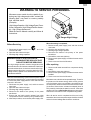
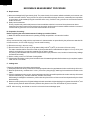
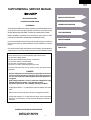
R- 405HK
R-405HW
R-403HW
SUPPLEMENTAL SERVICE MANUAL
S43M207R405HE
MICROWAVE OVENS
MODELS
R-405HK
R-405HK
R-405HW
R-403HW
In the interest of user-safety the oven should be restored to its original
condition and only parts identical to those specified should be used.
R-403HW
WARNING TO SERVICE PERSONNEL: Microwave ovens contain circuitry capable of producing very high voltage and
current, contact with following parts may result in a severe,
possibly fatal, electrical shock. (High Voltage Capacitor, High
Voltage Power Transformer, Magnetron, High Voltage Rectifier Assembly, High Voltage Harness etc..)
This is a supplemental Service Manual for Microwave Oven models R-405HK/HW & R-403HW. These models are quite
similar to the base models R410HK/R-410HW/R-409HK; (S33M206R410HE).
This supplemental manual must be used in conjunction with the base model service manual for complete operation,
service, safety and replacement parts information.
TABLE OF CONTENTS
Page
PRECAUTIONS TO BE OBSERVED BEFORE AND DURING SERVICING TO
AVOID POSSIBLE EXPOSURE TO EXCESSIVE MICROWAVE ENERGY .................. INSIDE FRONT COVER
BEFORE SERVICING ..................................................................................................... INSIDE FRONT COVER
WARNING TO SERVICE PERSONNEL .............................................................................................................. 1
MICROWAVE MEASUREMENT PROCEDURE .................................................................................................. 2
FOREWORD AND WARNING ............................................................................................................................. 3
PRODUCT SPECIFICATIONS ............................................................................................................................. 4
GENERAL INFORMATION ................................................................................................................................. 4
TEST PROCEDURE ..............................................................................................................................................6
CPU UNIT CIRCUIT ...............................................................................................................................................8
PARTS LIST ........................................................................................................................................................ 10
PACKING AND ACCESSORIES ......................................................................................................................... 14
SHARP ELECTRONCS CORPORATION
This document has been published to be used for after
sales service only.
The contents are subject to change without notice.
Service Headquarters: Sharp Plaza, Mahwah, New Jersey, 07430-2135
R-405HK
R-405HW
R-403HW
PRECAUTIONS TO BE OBSERVED BEFORE AND
DURING SERVICING TO AVOID POSSIBLE
EXPOSURE TO EXCESSIVE MICROWAVE
ENERGY
(a) Do not operate or allow the oven to be operated with the door open.
(b) Make the following safety checks on all ovens to be serviced before activating the magnetron or other
microwave source, and make repairs as necessary: (1) interlock operation, (2) proper door closing, (3)
seal and sealing surfaces (arcing, wear, and other damage), (4) damage to or loosening of hinges and
latches, (5) evidence of dropping or abuse.
(c) Before turning on microwave power for any service test or inspection within the microwave generating
compartments, check the magnetron, wave guide or transmission line, and cavity for proper alignment,
integrity, and connections.
(d) Any defective or misadjusted components in the interlock, monitor, door seal, and microwave generation
and transmission systems shall be repaired, replaced, or adjusted by procedures described in this
manual before the oven is released to the owner.
(e) A microwave leakage check to verify compliance with the Federal Performance Standard should be
performed on each oven prior to release to the owner.
BEFORE SERVICING
Before servicing an operative unit, perform a microwave emission check as per the
Microwave Measurement Procedure outlined in this service manual.
If microwave emissions level is in excess of the specified limit, contact SHARP
ELECTRONICS CORPORATION immediately @1-800-237-4277.
If the unit operates with the door open, service person should 1) tell the user
not to operate the oven and 2) contact SHARP ELECTRONICS CORPORATION and Food and
Drug Administration's Center for Devices and Radiological Health immediately.
Service personnel should inform SHARP ELECTRONICS CORPORATION of any certified unit
found with emissions in excess of 4mW/cm2. The owner of the unit should be instructed
not to use the unit until the oven has been brought into compliance.
R-405HK
R-405HW
R-403HW
WARNING TO SERVICE PERSONNEL
Microwave ovens contain circuitry capable of producing very high voltage and current, contact with
following parts may result in a severe, possibly
fatal, electrical shock.
(Example)
High Voltage Capacitor, High Voltage Power Transformer, Magnetron, High Voltage Rectifier Assembly, High Voltage Harness etc..
Read the Service Manual carefully and follow all
instructions.
Don't Touch !
Danger High Voltage
When the testing is completed,
1. Disconnect the power supply cord, and then remove
outer case.
2. Open the door and block it open.
3. Discharge high voltage capacitor.
4. Reconnect the leads to the primary of the power
transformer.
5. Reinstall the outer case (cabinet).
6. Reconnect the power supply cord after the outer case is
installed.
7. Run the oven and check all functions.
Before Servicing
1. Disconnect the power supply cord
remove outer case.
2. Open the door and block it open.
3. Discharge high voltage capacitor.
, and then
WARNING:RISK OF ELECTRIC SHOCK.
DISCHARGE THE HIGH-VOLTAGE
CAPACITOR BEFORE SERVICING.
After repairing
The high-voltage capacitor remains charged about 60
seconds after the oven has been switched off. Wait for 60
seconds and then short-circuit the connection of the highvoltage capacitor (that is the connecting lead of the highvoltage rectifier) against the chassis with the use of an
insulated screwdriver.
1. Reconnect all leads removed from components during
testing.
2. Reinstall the outer case (cabinet).
3. Reconnect the power supply cord after the outer case is
installed.
4. Run the oven and check all functions.
Whenever troubleshooting is performed the power supply
must be disconnected. It may, in some cases, be necessary
to connect the power supply after the outer case has been
removed, in this event:
1. Disconnect the power supply cord, and then remove
outer case.
2. Open the door and block it open.
3. Discharge high voltage capacitor.
4. Disconnect the leads to the primary of the power
transformer.
5. Ensure that the leads remain isolated from other
components and oven chassis by using insulation tape.
6. After that procedure, reconnect the power supply cord.
Microwave ovens should not be operated empty. To test for
the presence of microwave energy within a cavity, place a
cup of cold water on the oven turntable, close the door and
set the power to HIGH and set the microwave timer for two
(2) minutes. When the two minutes has elapsed (timer at
zero) carefully check that the water is now hot. If the water
remains cold carry out Before Servicing procedure and reexamine the connections to the component being tested.
When all service work is completed and the oven is fully
assembled, the microwave power output should be checked
and a microwave leakage test should be carried out.
1
R- 405HK
R-405HW
R-403HW
MICROWAVE MEASUREMENT PROCEDURE
A. Requirements:
1) Microwave leakage limit (Power density limit): The power density of microwave radiation emitted by a microwave oven
should not exceed 1mW/cm2 at any point 5cm or more from the external surface of the oven, measured prior to acquisition
by a purchaser, and thereafter (through the useful life of the oven), 5 mW/cm2 at any point 5cm or more from the external
surface of the oven.
2) Safety interlock switches:
Primary interlock relay switch shall prevent microwave radiation emission in excess of the requirement as above
mentioned. Secondary interlock relay and door sensing switch shall prevent microwave radiation emission in excess of
5 mW/cm2 at any point 5cm or more from the external surface of the oven.
B. Preparation for testing:
Before beginning the actual measurement of leakage, proceed as follows:
1) Make sure that the actual instrument is operating normally as specified in its instruction booklet.
Important:
Survey instruments that comply with the requirement for instrumentation as prescribed by the performance standard for
microwave ovens, 21 CFR 1030.10(c)(3)(i), must be used for testing.
2) Place the oven tray in the oven cavity.
3) Place the load of 275±15 ml (9.8 oz) of tap water initially at 20±5O C (68OF) in the center of the oven cavity.
The water container shall be a low form of 600 ml (20 oz) beaker with an inside diameter of approx. 8.5 cm (3-1/2 in.) and
made of an electrically nonconductive material such as glass or plastic.
The placing of this standard load in the oven is important not only to protect the oven, but also to insure that any leakage
is measured accurately.
4) Set the cooking control on Full Power Cooking Mode.
5) Close the door and select a cook cycle of several minutes. If the water begins to boil before the survey is completed, replace
it with 275 ml of cool water.
C. Leakage test:
Closed-door leakage test (microwave measurement):
1) Grasp the probe of the survey instrument and hold it perpendicular to the gap between the door and the body of the oven.
2) Move the probe slowly, not faster than 1 in./sec. (2.5 cm/sec.) along the gap, watching for the maximum indication on the
meter.
3) Check for leakage at the door screen, sheet metal seams and other accessible positions where the continuity of the metal
has been breached (eg., around the switches, indicator, and vents).
While testing for leakage around the door, pull the door away from the front of the oven as far as is permitted by the closed
latch assembly.
4) Measure carefully at the point of highest leakage and make sure that the highest leakage is no greater than 4mW/cm2, and
that the primary interlock switch/secondary interlock relay does turn the oven OFF before any door movement.
NOTE: After servicing, record data on service invoice and microwave leakage report.
2
R-405HK
R-405HW
R-403HW
SUPPLEMENTAL SERVICE MANUAL
PRODUCT DESCRIPTION
MICROWAVE OVENS
R-405HK/R-405HW/R-403HW
GENERAL INFORMATION
FOREWORD
This supplemental Manual has been prepared to provide Sharp Electronics
Corp. Service Personnel with Operation and Service Information for the
SHARP MICROWAVE OVENS, R-405HK, R-405HW and R-403HW.
TEST PROCEDURE
Models R-405HK, R-405HW and R-403HW are quite similar to base
models R-410HK/HW & R-409HK (Ref.# S33M206R410HE)
It is recommended that service personnel carefully study the entire text of
this manual so that they will be qualified to render satisfactory customer
service.
Check the interlock switches and the door seal carefully. Special attention
should be given to avoid electrical shock and microwave radiation hazard.
WARNING
Never operate the oven until the following points are ensured:
(A) The door is tightly closed.
(B) The door brackets and hinges are not defective.
(C) The door packing is not damaged.
(D) The door is not deformed or warped.
(E) There is no other visible damage with the oven.
Servicing and repair work must be carried out only by trained service
personnel.
DANGER
Certain initial parts are intentionally not grounded and present
a risk of electrical shock only during servicing. Service personnel - Do not contact the following parts while the appliance is
energized;
High Voltage Capacitor, Power Transformer, Magnetron, High
Voltage Rectifier Assembly, High Voltage Harness;
If provided, Vent Hood, Fan assembly, Cooling Fan Motor.
All the parts marked “*” on parts list are used at voltages more than
250V.
Removal of the outer wrap gives access to voltage above 250V.
All the parts marked “∆” on parts list may cause undue microwave
exposure, by themselves, or when they are damaged, loosened or
removed.
SHARP ELECTRONICS CORPORATION
SHARP PLAZA, MAHWAH,
NEW JERSEY 07430-2135
3
WIRING DIAGRAM
PARTS LIST
R- 405HK
R-405HW
R-403HW
SPECIFICATION
ITEM
DESCRIPTION
Power Requirements
120 Volts
14.0 Amperes, 1600 watts
60 Hertz
Single phase, 3 wire grounded
Power Output
1100 watts (IEC 705 TEST PROCEDURE)
Operating frequency of 2450MHz
Case Dimensions
Width 21-11/16"
Height 12-3/8"
Depth 17-3/8"
Cooking Cavity Dimensions
Width 15"
Height 9-7/16"
Depth 16-3/4"
1.4 Cubic Feet
Control Complement
Oven Cavity Light
Safety Standard
Touch Control System
Clock ( 1:00 - 12:59 )
Timer (0 - 99 min. 99 seconds)
Microwave Power for Variable Cooking
Repetition Rate;
P-HI .................................................. Full power throughout the cooking time
P-90 .................................................................... approx. 90% of Full Power
P-80 .................................................................... approx. 80% of Full Power
P-70 .................................................................... approx. 70% of Full Power
P-60 .................................................................... approx. 60% of Full Power
P-50 .................................................................... approx. 50% of Full Power
P-40 .................................................................... approx. 40% of Full Power
P-30 .................................................................... approx. 30% of Full Power
P-20 .................................................................... approx. 20% of Full Power
P-10 .................................................................... approx. 10% of Full Power
P-0 ...................................................... No power throughout the cooking time
MINUTE PLUS button, Cook center, Defrost center, Number selection pads,
Power Level pad, Timer/Clock pad,Stop/Clear pad, Reheat Center, Popcorn and
Minute plus.
Yes
UL Listed
FCC Authorized
DHHS Rules, CFR, Title 21, Chapter 1, Subchapter J
GENERAL INFORMATION
GROUNDING INSTRUCTIONS
This oven is equipped with a three prong grounding plug. It must be plugged into a wall receptacle that is properly installed
and grounded in accordance with the National Electrical Code and local codes and ordinances.
In the event of an electrical short circuit, grounding reduces the risk of electric shock by providing an escape wire for the electric
current.
WARNING:
Improper use of the grounding plug can result in a risk of electric shock.
Electrical Requirements
The electrical requirements are a 120 volt 60 Hz, AC only,
15 or 20 amp. fused electrical supply. It is recommended that a separate circuit serving only this appliance be provided. When
installing this appliance, observe all applicable codes and ordinances.
A short power-supply cord is provided to reduce risks of becoming entangled in or tripping over a longer cord.
Where a two-pronged wall-receptacle is encountered, it is the personal responsibility and obligation of the customer to contact
4
R-405HK
R-405HW
R-403HW
a qualified electrician and have it replaced with a properly grounded
three-pronged wall receptacle or have a grounding adapter properly
grounded and polarized. If the extension cord must be used, it should be
a 3-wire, 15 amp. or higher rated cord. Do not drape over a countertop
or table where it can be pulled on by children or tripped over accidentally.
Grounded
Receptacle Box
3-Pronged
CAUTION: DO NOT UNDER ANY CIRCUMSTANCES CUT OR RE- Plug
MOVE THE ROUND GROUNDING PRONG FROM THIS
Grounding Pin
PLUG.
3-Pronged Receptacle
OVEN DIAGRAM
1. One touch door open button.
Push to open door.
2. Door latches.
The oven will not operate unless the
door is securely closed.
3. Removable turntable support.
4. Removable turntable.
The turntable will rotate clockwise or
counterclockwise.
5. Oven lamp.
It will light when oven is operating or
door is opened.
6. Oven door with see-through window.
7. Ventilation openings. (Rear)
8. Auto-Touch control panel.
9. Time display: Digital display, 99
minutes 99 seconds.
NOTE:
The directed features are disabled after one minute when the
oven is not in use. These features
are automatically enabled when
the door is opened and closed or
the STOP/ CLEAR pad is pressed.
6
9
5
7
11
8
2
10
1
4
R-405HK/HW
3
10. Wave guide cover.
11. Power supply cord
TOUCH CONTROL PANEL
R-405HK
5
R-403HW
R- 405HK
R-405HW
R-403HW
TEST PROCEDURES
PROCEDURE
LETTER
J
COMPONENT TEST
KEY UNIT TEST
1.
2.
3.
4.
5.
6.
7.
8.
Disconnect the power supply cord, and then remove outer case.
Open the door and block it open.
Discharge high voltage capacitor.
Using an ohmmeter and referring to the key unit matrix indicated on the control unit circuit, check the
circuit between the pins of the key unit that correspond to the CLEAR pad. When the pad is pressed,
the ohmmeter should indicate short circuit. When the pad is released, the ohmmeter should indicate
open circuit. If incorrect readings are obtained, the key unit is faulty and must be replaced. About the
other pads, the above method may be used.
Reconnect all leads removed from components during testing.
Re-install the outer case (cabinet).
Reconnect the power supply cord after the outer case is installed.
Run the oven and check all functions.
6. Re-install the outer case (cabinet).
7. Reconnect the power supply cord after the outer case is installed.
8. Run the oven and check all functions.
G8
G7
G6
G9
G12
G10
G11
POPCORN
DEFROST
*
MINUTE
PLUS
*
Pin
NO. G13
*START
COOK
G3
G2
G1
CLEAR
REHEAT
2
1
4
7
5
TIMER
CLOCK
9
8
0
POWER
LEVEL
3
6
When door is close, key can be operated.
Key unit ribbon cable
G4
G3
G10
G8
G7
G6
G2
REHEAT
2
START
1
4
7
5
TIMER
CLOCK
9
8
0
STOP
CLEAR
3
6
G1
R-403HW
G12
G9
G5
G11
Key unit (Membrane Switch) front view
DEFROST
G13
Pin
NO. G1
G4
*
G13
R-405HK/HW
G5
STOP
CLEAR
COOK
Key Unit
6
POWER
LEVEL
MINUTE
PLUS
POPCORN
R-405HK
R-405HW
R-403HW
TEST PROCEDURES
PROCEDURE
LETTER
L
COMPONENT TEST
DEFROST TEST (R-405HK/HW)
WARNING : The oven should be fully assembled before following procedure.
(1) Place one cup of water in the center of the turntable tray in the oven cavity.
(2) Open the door.
(3) Touch the " DEFROST " pad.
(4) Touch the number pad " 2 ".
(5) Touch the number pad " 5 ".
(6) Close the door.
(7) Touch the "START " pad.
(8) The oven is in Defrost cooking condition.
(9) The oven will operate as follows
MENU
1ST STAGE
STEAKS/CHOPS LEVEL
TIME
0.5lb
60%
20sec.
2ND STAGE
LEVEL
TIME
40%
20sec.
3RD STAGE
LEVEL TIME
30%
45sec.
(10) If improper operation is indicated, the control unit is probably defective and should be checked.
DEFROST TEST (R-403HW)
WARNING : The oven should be fully assembled before following procedure.
(1) Place one cup of water in the center of the turntable tray in the oven cavity.
(2) Close the door.
(3) Touch the " DEFROST " pad.
(4) Touch the number pad " 2 ".
(5) Touch the number pad " 5 ".
(6) Touch the "START " pad.
(7) The oven is in Defrost cooking condition.
(8) The oven will operate as follows
MENU
1ST STAGE
STEAKS/CHOPS LEVEL
TIME
0.5lb
60%
20sec.
2ND STAGE
LEVEL
TIME
40%
20sec.
3RD STAGE
LEVEL TIME
30%
45sec.
(9) If improper operation is indicated, the control unit is probably defective and should be checked.
7
COM
DOOR
SENSING
SWITCH
B-2
B-1
COM
POWER
TRANSFORMER
AC(H) NO
OVEN LAMP
TURNTABLE
MOTOR
FAN MOTOR
AC(N) NO
2
WH-1
WH-1
1
(J1)
0.1uF
50V
C1
RY1
DU12D1-1P(M)-R
c
b
NOTE
D31 1SS270A
D30 1SS270A
RY2
DU12D1-1P(M)-R
D7
D8
VRS1
10G471K
a
d
1SS270A
1SS270A
C2
D6
Q4
DTA123JS
10u/35V
C5
DTD143ES
Q3
SP1
R5
Q2
2SA933AS
4.7K 1/4W
47uF/16V
BL
-5 V
BZ
C11
DOOR
M
NL
COM
R12
15K
CPU UNIT
Q20
DTA143EKA
(G)
15K
R41
0.1uF50V
C20
Q30
DTA143EKA
Q102
SA1037AK
15K
R72
15K
P45 R71
15K
P41 R70
15K
P71 R69
15K
P70 R68
AN4
(J10)
0.01uF25V
15K
C14
R11
R74 - R78:270Kx5
4.7K
C13
C12
0.1uF50V
0.1uF/50V
(F)
0.01uF25V
(J12)
AN5
4.7K
AN6
(J16)
GND
AN7
C60 - C64:330pF/50Vx5
(J13)
3.6K
4.7K
15K
DEFROST
*
10K
10K
(G)
R15
R14
G6
STOP
CLEAR
COOK
*START
*MINUTE
PLUS
G7
AN7
AN6
AN5
25
INT0
P43
P44
P45
P46
P47
P50
P51
P52
P53
CNTR0
P55
P56
P57
AN0
AN1
AN2
AN3
AN4
VL2
80
VL1
1
IC1
64
41
(F)
CST4.00MGW
40
P17
P16
P15
P14
P13
P12
SEG25
SEG24
SEG23
SEG22
SEG21
SEG20
SEG19
SEG18
SEG17
SEG16
SEG15
SEG14
SEG13
SEG12
SEG11
SEG10
SEG9
SEG8
65
9
3
6
POWER
LEVEL
G2
TIMER
CLOCK
CLEAR
G3
CF1
Key can be operated.
8
0
5
1
4
7
G4
2
G5
REHEAT
24
*When door is close,
POPCORN
G8
15K
R110
10K
R13
COOK DEFROST SENSOR AUTO%
NO.
LBS.
CUPS
KG OZ.
LIQUID CRYSTAL DISPLAY
KEY UNIT
G1
5
Figure S-3. CPU Unit Circuit (R-405HK/HW)
:IF NOT SPECIFIED 1/10W±5%
POWER UNIT
27 1/4 W
R4
1SS270A x2
D5
510
1/2 W
JUMPER
WIER
2200uF
25V
R3
C10
R2
R10
ZD10
R40
T1
R6
1K
UDZ4.3B
4.7K
PA151DR
C4
3.3K
1/4W
Q11
DTA143EKA
00.01uF 25V
INT
3.6K
C64
COM3
COM2
COM1
COM0
COM1
COM2
15K
(J11)
R78
R77
R76
R75
R74
(J15)
C63
P24
4.7K
(J14)
C62
P27
R67
20K
C61
P25
R65
P41
P40
R64
(J17)
C60
P26
R66
SEG21
SEG20
SEG19
SEG18
SEG17
SEG16
SEG15
SEG14
SEG13
SEG12
SEG11
SEG10
RESET
15K
GND
G9
G10
5
G11
P23
R63
4
G12
4
G13
R80
8
15K
3
1M
2
15K
SEG9
SEG8
SEG7
SEG6
SEG5
SEG4
SEG3
SEG2
SEG1
SEG0
VL3
COM0
COM1
COM2
COM3
AVSS
VREF
VCC
SEG0
SEG1
SEG2
SEG3
SEG4
SEG5
SEG6
SEG7
1
P22
LD4 LD3 LD2 LD1
P71
P70
XIN
XOUT
VSS
P27
P26
P25
P24
P23
P22
P21
P20
H
15K
G
P21
E
R62
C
R61
D
3
15K
F
2
P20
1
R60
A
15K
B
D1 - D4
1N4002x4
R- 405HK
R-405HW
R-403HW
6
A
B
C
6
D
E
F
G
H
5
DOOR
SENSING
SWITCH
B-2
B-1
POWER
COM
TRANSFORMER
AC(H) NO
OVEN LAMP
TURNTABLE COM
MOTOR
FAN MOTOR
AC(N) NO
2
WH-1
WH-1
1
b
0.1uF
50V
RY1
DU12D1-1P(M)-R
c
(J1)
NOTE
D31 1SS270A
D30 1SS270A
RY2
DU12D1-1P(M)-R
C2
D6
SP1
Q4
DTA123JS
10u/35V
C5
DTD143ES
Q3
R5
Q2
2SA933AS
4.7K 1/4W
BL
-5 V
BZ
C11
DOOR
M
NL
COM
:IF NOT SPECIFIED 1/10W±5%
POWER UNIT
27 1/4 W
R4
1SS270A x2
D5
510
1/2 W
2200uF
25V
JUMPER
WIER
C10
R3
R6
C1
D7
D8
47uF/16V
3.3K
1/4W
R2
C12
0.1uF50V
0.1uF/50V
R12
15K
(G)
15K
R41
0.1uF50V
C20
Q30
DTA143EKA
15K
R72
15K
P45 R71
15K
P41 R70
15K
P71 R69
15K
P70 R68
AN4
(J10)
(J11)
0.01uF25V
15K
C14
R11
R74 - R78:270Kx5
AN5
10K
AN6
AN7
C60 - C64:330pF/50Vx5
15K
R110
10K
R13
DEFROST
G8
COOK DEFROST SENSOR AUTO%
10K
10K
(G)
R15
R14
G7
AN7
24
25
INT0
P43
P44
P45
P46
P47
P50
P51
P52
P53
CNTR0
P55
P56
P57
AN0
AN1
AN2
AN3
AN4
AN5
AN6
VL2
80
VL1
1
COOK
G6
IC1
2
5
REHEAT
1
4
7
8
0
G4
G5
POWER
LEVEL
STOP
CLEAR
TIMER
CLOCK
START
G3
CF1
64
41
(F)
CST4.00MGW
40
P17
P16
P15
P14
P13
P12
SEG25
SEG24
SEG23
SEG22
SEG21
SEG20
SEG19
SEG18
SEG17
SEG16
SEG15
SEG14
SEG13
SEG12
SEG11
SEG10
SEG9
SEG8
65
NO.
LBS.
CUPS
KG OZ.
3
6
9
G2
15K
KEY UNIT
POPCORN
MINUTE
PLUS
G1
5
Figure S-3. CPU Unit Circuit (R-403HW)
CPU UNIT
Q20
DTA143EKA
(F)
C13
R10
ZD10
R40
VRS1
10G471K
a
1SS270A
0.01uF25V
1K
UDZ4.3B
4.7K
d
00.01uF 25V
PA151DR
C4
1SS270A
Q102
SA1037AK
C64
T1
3.6K
(J12)
(J13)
3.6K
4.7K
4.7K
(J14)
(J15)
C63
4.7K
R78
R77
R76
R75
R74
(J16)
C61
Q11
DTA143EKA
P27
R67
4.7K
C62
COM3
COM2
COM1
COM0
COM1
COM2
INT
P25
R65
(J17)
C60
LIQUID CRYSTAL DISPLAY
15K
P24
R64
P41
P40
GND
15K
P26
R66
SEG21
SEG20
SEG19
SEG18
SEG17
SEG16
SEG15
SEG14
SEG13
SEG12
SEG11
SEG10
RESET
15K
GND
G9
G10
G11
P23
R63
4
G12
4
G13
R80
9
15K
3
1M
2
15K
SEG9
SEG8
SEG7
SEG6
SEG5
SEG4
SEG3
SEG2
SEG1
SEG0
VL3
COM0
COM1
COM2
COM3
AVSS
VREF
VCC
SEG0
SEG1
SEG2
SEG3
SEG4
SEG5
SEG6
SEG7
1
P22
H
R62
LD4 LD3 LD2 LD1
P71
P70
XIN
XOUT
VSS
P27
P26
P25
P24
P23
P22
P21
P20
G
15K
F
P21
E
3
R61
D
15K
C
2
P20
1
R60
B
D1 - D4
1N4002x4
R-405HK
R-405HW
R-403HW
6
A
A
B
C
6
D
E
F
G
H
R- 405HK
R-405HW
R-403HW
PARTS LIST
∆” may cause undue microwave exposure.
Note: The parts marked “∆
The parts marked “*” are used in voltage more than 250V. "§" MARK: PARTS DELIVERY SECTION.
REF. NO.
PART NO.
§
DESCRIPTION
1- 1
1- 2
1- 3
1- 4
1- 5
1- 6
1- 7
1- 8
1- 9
1-10
1-11
1-12
RC-QZB018MRE0
FH-DZB013MRY0
QSOCLB006MRE0
RLMPTA086WRZZ
RMOTEA346WRE0
FFS-BA019/KIT
QSW-MA085WRE0
QFS-TA014WRE0
RV-MZA293WRE0
RMOTDA211/KIT
RTRN-B077MRE0
FACCDB003MRE0
M
M
M
M
M
M
M
M
M
M
M
M
High voltage capacitor
High voltage rectifier assembly
Oven lamp socket
Oven lamp
Fan motor
Monitor switch (V-16G-2C25), C/T fuse (20A 250V AC) & Inst.
Primary interlock switch and door sensing switch (V-5230Q)
Cavity temperature fuse 150OC
Magnetron
Turntable motor
Power transformer
Power supply cord
2222-
GDAI-B068MRP0
GLEGPB004MRF0
GCABUB097MRP0
GCABUB088MRP0
M
M
M
M
Base plate
Foot
Outer case cabinet [R-405HK]
Outer case cabinet [R-403HW/R-405HW]
Q'TY CODE
ELECTRIC PARTS
∆
1
1
1
1
1
1
2
1
1
1
1
1
AQ
AK
AE
AD
AR
AF
AE
AF
BC
AL
BZ
AM
1
4
1
1
AN
AB
AT
AU
1
1
1
1
1
1
1
1
1
1
1
1
1
5
BA
BA
BA
AE
AE
AF
AG
AG
AG
AD
AF
AD
AA
AA
1
1
1
1
1
1
1
1
1
1
1
AB
AD
AF
AD
AM
AC
AC
-AC
AA
AA
1
1
1
1
1
1
1
1
1
1
1
1
3
3
3
1
AW
AW
BB
AD
AB
AQ
AE
AG
AA
AQ
AQ
AN
AD
AB
AC
AA
CABINET PARTS
1
2
3
3
CONTROL PANEL PARTS
33333333333333-
1
1
1
2
2
2
3
3
3
4
4
4
5
6
GPNLCB037/KIT
GPNLCB037/KITA
GPNLCB036/KIT
HPNLFB005MRF0A
HPNLFB007MRF0A
HPNLFB004MRF0A
PSHEPB114MRR0
PSHEPB124MRR0
PSHEPB115MRR0
JBTN-B151MRF0A
JBTN-B155MRF0A
JBTN-B150MRF0A
MSPRCA045WRE0
XEPSD30P06XS0
M
M
M
M
M
M
M
M
M
M
M
M
M
M
Control unit assy [R-405HK]
Control unit assy [R-405HW]
Control unit assy [R-403HW]
Control panel frame [R-405HK]
Control panel frame [R-405HW]
Control panel frame [R-403HW]
Graphic sheet [R-405HK]
Graphic sheet [R-405HW]
Graphic sheet [R-403HW]
Open button [R-405HK]
Open button [R-405HW]
Open button [R-403HW]
Open button spring
Screw; 3mm x 6mm
OVEN PARTS
4- 1
4- 2
4- 3
4- 4
4- 5
4- 6
4- 7
4- 8
4- 9
4-10
4-11
LBNDKB007MRP0
M
LANGTB060MRP0
M
PHOK-B018MRF0
M
MLEVPB016MRF0
M
PDUC-B120MRF0A M
NFANPB001MRE0
M
PDUC-B088MRF0
M
------------M
PCOVPB073MRP0
M
PPACGB014MRF0
M
PCUSUB033MRP0
M
H.V. Capacitor band
Chassis support
Latch hook
Switch lever
Magnetron duct
Fan blade
Fan duct
Oven cavity
(Not a replaceable part)
Waveguide cover
Turntable motor packing
Cushion
DOOR PARTS
5 -1
5 -1
5 -1
5-1-1
5-1-2
5 -2
5- 3
5- 4
5- 5
5- 6
5- 6
5- 6
5- 7
5- 7
5- 8
5- 9
FCOV-B234MRK0
M
FCOV-B238MRK0
M
FCOV-B233MRK0
M
LSTPPB021MRF0
M
MSPRTA046WRE0
M
FDORFB074MRT0
M
PSHEPB021MRE0
M
GCOVHB046MRF0
M
LSTPPB044MRF0
M
HPNL-B105MRE0
M
HPNL-B106MRE0
M
HPNL-B104MRE0
M
JBTN-B152MRF0A M
JBTN-B156MRF0A M
MSPRTB022MRE0
M
PCUSGB033MRP0
M
Door frame assembly [R-405HK]
Door frame assembly [R-405HW]
Door frame assembly [R-403HW]
Latch head
Latch spring
Door panel
Sealer film
Choke cover
Door stopper
Door screen [R-405HK]
Door screen [R-405HW]
Door screen [R-403HW]
Door button [R-405HK]
Door button [R-405HW]
Button spring [R-405HK/R-405HW]
Cushion [R-405HK/R-405HW]
10
R-405HK
R-405HW
R-403HW
REF. NO.
PART NO.
§
DESCRIPTION
Q'TY CODE
MISCELLANEOUS
666666666-
1
2
3
4
5
6
7
7
8
FW-VZB125MRE0
FW-VZB192MRE0
FROLPB025MRK0
NTNT-A108WREZ
TCAUAB045MRR0
TCAUAB038MRR0
TINSEB355MRK0
TINSEB333MRK0
QW-QZB016MRE0
M
M
M
M
M
M
M
M
M
Stop switch harness
Main wire harnes
Turntable support
Turntable tray
Monitor caution label
DHHS/Screw caution label
Operation manual [R-405HK/HW]
Operation manual [R-403HW]
High voltage wire A
7777777-
1
2
3
4
5
6
7
LX-BZA041WRE0
LX-CZ0052WRE0
XHTSD40P12RV0
XOTSE40P12000
XCBSD30P08000
XHTSD40P08RV0
LX-CZA070WRE0
M
M
M
M
M
M
M
Special
Special
Screw :
Screw :
Screw :
Screw :
Special
1
1
1
1
1
1
1
1
1
AF
AU
AN
AM
AA
AB
AD
AD
AC
5
2
1
8
3
3
2
AA
AA
AA
AA
AA
AA
AA
SCREWS,NUTS AND WASHERS
screw
screw
4mm x
4mm x
3mm x
4mm x
screw
12mm
12mm
8mm
8mm
(Torx tamper proof screw)
HOW TO ORDER REPLACEMENT PARTS
To have your order filled promptly and correctly, please furnish the following information.
1. MODEL NUMBER
2. REF. NO.
3. PART NO.
4. DESCRIPTION
Order Parts from the authorized SHARP parts Distributor for your area.
Defective parts requiring return should be returned as indicated in the Service Policy.
11
R- 405HK
R-405HW
R-403HW
2
1
4
3
6
5
OVEN AND CABINET PARTS
7-4
A
A
7-4
7-7
2-3
B
B
4-7
7-7
6-6
7-5
1-8
C
C
1-5
4-6
7-3
7-5
1-12
D
4-8
1-6
7-6
D
4-2
7-4
E
4-9
1-9
6-5
7-2
1-4
7-2
6-4
1-10
F
1-11
7-5
F
1-6
2-1
6-3
4-5
7-1
1-7
4-3
4-10
E
1-3
1-7
7-1
4-4
4-1
1-1
1-2
G
G
7-4
7-4
2-2
2-2
7-4
2-2
4-11
2-2
H
H
1
2
4
3
12
5
6
R-405HK
R-405HW
R-403HW
2
1
Control Panel Parts
4
3
6
5
3-1
A
3-2
A
5-5
R-405HK/HW
5-3
3-6
5-4
5-1
3-3
B
B
5-2
3-5
3-4
5-9
5-1-1
C
C
5-1-2
5-7
Items 5-9, 5-6 & 5-7 are not included with assembly 5-1
Door Parts
5-8
5-6
D
D
3-3
3-1
Control Panel Parts
3-6
R-403HW
E
5-5
E
5-4
3-5
3-2
3-4
5-2
F
F
5-3
Miscellaneous
6-1
5-1-1
G
G
5-1-2
6-2
6-8
Door Parts
5-1
Actual wire harness may be different from illustration.
H
H
5-6
1
2
4
3
13
5
6
R- 405HK
R-405HW
R-403HW
PACKING AND ACCESSORIES
TOP PAD ASSEMBLY
DOOR PROTECTION SHEET
6-4 TURNTABLE TRAY
PLASTIC BAG
ON TOP OF THE OVEN
TRAY HOLDER
6-7 OPERATION MANUAL
IN
TO
E
TH
EN
OV
Y
VIT
CA
BOTTOM PAD ASSEMBLY
6-3 TURNTABLE SUPPORT
PACKING CASE
Non-replaceable items
14
R-405HK
R-405HW
R-403HW
NOTES
15
R- 405HK
R-405HW
R-403HW
NOTES
16
R-405HK
R-405HW
R-403HW
NOTES
17
R- 405HK
R-405HW
R-403HW
COPYRIGHT © 2003 BY SHARP CORPORATION
ALL RIGHTS RESERVED.
No part of this publication may be reproduced, stored in retrieval systems, or transmitted in any form or by any means, electronic, mechanical, photocopying, recording,
or otherwise, without prior written permission
of the publisher.
2003SHARP CORP. (3M2.00E) Printed in U.S.A
18