1
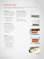
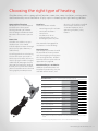
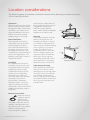
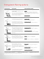
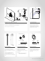
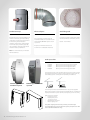
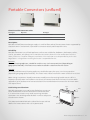
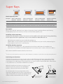
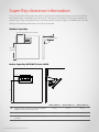
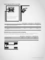
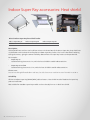
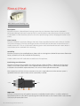
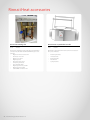
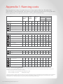
Specification guide
Heating
About this guide
This guide has been written to help you select and
order the right Rinnai heating system and associated
components for the right job. This information is not
intended as an installation guide.
Rinnai is constantly improving its products, and as
such, information and specifications are subject to
change or variation without notice. For the most upto-date information go to www.rinnai.co.nz.
For more information about buying, using, and
servicing of Rinnai appliances call: 0800 RINNAI
(0800 746 624)
Rinnai New Zealand Limited
105 Pavilion Drive, Mangere, Auckland
PO Box 53177, Auckland Airport, Auckland 2150
Phone: (09) 257 3800, Fax: (09) 257 3899
Email: [email protected]
Web: www.rinnai.co.nz, www.youtube.com/rinnainz
www.rinnaitraining.co.nz (installer training)
www.facebook.com/rinnainz
:
s
t
n
e
t
n
co
Heating range.................................................................4
Appendices
Choosing the right type of heating.................................5
Appendix 1: Running costs...............................................30
Location considerations..................................................6
Appendix 2: Calculating the minimum room size............32
Rinnai iHeat: Determining suitability..............................7
Appendix 3: Energysaver 1004FTR remote wiring diagram..33
Appendix 4: Definition of an outdoor area.....................34
Product specification pages
Energysavers...................................................................9
Energysaver specification summary................................10
Energysaver dimensions (mm)........................................11
Energysaver flueing guidelines.......................................13
Energysaver flue components........................................14
Portable convectors (unflued)........................................17
Portable convector specification summary....................18
Portable convector accessories......................................19
Super Rays.......................................................................20
Super Ray specification summary...................................21
Super Ray clearance information....................................22
Super Ray accessories: Heat shield.................................24
Super Ray accessories: Deluxe surround.........................25
Rinnai iHeat central heating system................................26
Rinnai iHeat specification summary................................27
Rinnai iHeat accessories..................................................28
Heating range
Rinnai provide fast and reliable heating. Hallmarks of our product range are precise
temperature control and energy efficient heating.
Energysavers
These are fixed power flued
heaters. Rinnai appliances flued
via a power flue are approved by
the sensitive choice programme
of the Asthma Foundation.
Four models to choose from:
• Energysaver 309FT
• Energysaver 559FT
• Energysaver 561FT
• Energysaver 1004FTR
Portable Convectors
These are unflued portable
gas heaters, which can be
unplugged and moved from
one gas wall or floor socket to
another around the home, and
can be tucked away in summer.
Rinnai iHeat®(RAHU20)
The Rinnai iHeat is a ducted
home heating system that uses
hot water from your Rinnai
INFINITY®continuous flow gas
hot water heater to warm air
and circulate it around your
home.
Energysaver 559FT
Refer to the product
specification pages for each
model to determine suitability.
Portable Convector Avenger
Two models to choose from:
• Avenger 671
• Dynamo 471
Super Rays
These are infra-red radiant
heaters that are great for
spot heating in large spaces.
Unaffected by external air
currents, the heat is channelled
to specific areas.
Seven models to choose from:
• Indoor Super Ray 16*
• Indoor Super Ray 24*
• Indoor Super Ray 40*
• ODHRAD3M (outdoor)
Outdoor Super Ray
Indoor Super Ray
* Choice of manual or electronic
models
Rinnai iHeat
4 | Rinnai Heating Specification Guide 02-13
Choosing the right type of heating
Considerations such as geographical location, room size, room insulation, running costs,
and functionality versus aesthetics all play a part in choosing the right heating solution.
Geographical location
Where you live in New Zealand
can determine the type of
heating solution you choose.
Use the diagram below to work
out which climate zone you are
in.
Room size
Consider the whole area you
need to heat. This should
include adjacent rooms through
permanently open doorways
and hallways.
A useful guide when calculating
the size of heater you need is
to measure the room volume in
metres (length x width x height)
and divide by 20 to get the kW
rating of the appliance needed.
If there are any heat loss factors
you will need to increase the kW
rating slightly to compensate.
Heat loss
Heat loss factors include:
-------
no ceiling or wall insulation
no carpets on floors
no curtains
window area >15 m²
ceiling height > 2.4 m²
building on poles or piles
where it is likely to be installed.
For example are timers and
a remote important, or is
operating simplicity a key
factor?
Also consider how good the
insulation is in the building.
Running costs
Upfront purchase costs should
be considered in conjunction
with the ongoing running costs
of a heating solution. To work
out what these may be refer to
appendix 1 on page 30.
Functionality vs. aesthetics
Additional considerations are
based on functionality, the size
and look of the heater, and
heating area (based on a standard ceiling height of 2.4 m)
Warm zone Medium
zone
Me
diu
m
Warm
Cool
Cool Zone
Energysaver 309FT
45 m2
31 m2
26 m2
Energysaver 559FT
77 m2
53.5 m2
45.5 m2
Energysaver 561FT
70 m2
48 m2
41 m2
Energysaver 1004FTR
119 m2
82 m2
69 m2
Portable Convector Dynamo 471*
51.5 m2
45 m2
38 m2
Portable Convector Avenger 671*
95 m2
80 m2
70 m2
Indoor Super Ray 16**
19 m2
19 m2
19 m2
Indoor Super Ray 24**
28 m2
28 m2
28 m2
Indoor Super Ray 40**
47 m2
47 m2
47 m2
Outdoor Super Ray
23 m2
23 m2
23 m2
Rinnai iHeat
333 m²
285 m²
250 m2
* These heaters are subject to a minimum room size, refer specification pages for further
detail
** The Indoor Super Ray heaters are for commercial and industrial use only
Rinnai Heating Specification Guide 02-13 | 5
Location considerations
Clearances
All Rinnai appliances are subject
to clearances. Examples for the
Energysaver 559FT and Portable
Convectors are shown on this
page. For additional clearance
details, refer to the specific
product pages in this guide.
Fixed ventilation
Rinnai Portable Convectors
and Indoor Super Ray heaters
(unflued appliances) draw
the air for combustion from
the room, so there is a need
for adequate ventilation. This
ventilation must be provided as
per the Gas Regulations—the
gasfitter installing the heater is
responsible for this.
Suitability
It is important to review the
suitability statements for each
heating solution, for example;
Indoor Super Rays are only
suitable for commercial and
industrial use and Portable
Convectors are subject to
minimum room sizes. Portable
Convectors also cannot
be installed in a bedroom,
bathroom, toilet, sauna, spa
room, or hallway. For further
information, refer to each of the
product specification pages in
this guide.
Electrical connection
All Rinnai heating
solutions require
electricity to
operate (except
the Indoor Super Ray manual
models). Consideration must
be made as to where the power
point can be positioned.
A 3-pin plug with a 1500 mm
6 | Rinnai Heating Specification Guide 02-13
power cord is supplied with all
Rinnai appliances. This must be
plugged into a dedicated
230 V 10 A earthed power
point. Power boards and double
adaptors must not be used.
Flooring
Heat emanating from the front
of Rinnai Energysavers and
Portable Convectors may over
time affect the appearance of
some materials used for flooring
such as carpet, vinyl, cork or
timber. This effect may be
amplified if the air in the room
contains cooking vapours or
cigarette smoke. To avoid this
occurring a mat or rug may
need to be positioned in front
of the appliance—extending
about one metre in front of it.
Super Ray positioning
Super Ray heaters direct their
heat via infra-red rays, which
discharge the heat energy upon
striking a surface. They do not
pass through solid materials.
From a heating and safety point
of view obstructions to the path
of the rays must be taken into
consideration.
250 mm
The following general guidelines should be factored when deciding on where to position
a Rinnai heating solution.
TOP
FRONT
1000 mm
50 mm
50 mm
LEFT SIDE
RIGHT SIDE
Energysaver 559FT clearances
50mm
50mm
50mm
50mm
750mm
Portable Convector clearances
Rinnai iHeat®:Determining suitability
Spending time in the planning stages and discussing the heating requirements with the
customer will ensure the correct system is specified and that the Rinnai iHeat can be
successfully installed.
Prior to purchase
Prior to purchase of a Rinnai iHeat a customer site visit is required to cover off the following areas:
• Determining the current hot water system
What hot water system currently exists at the property, where it is located, what is the static water
pressure, and is water quality an issue?
• Addressing if a Rinnai iHeat system can be installed at the property
Can the system be positioned in a location that meets the clearance and access requirements, and
in a location where operating noise of the Rinnai INFINITY®gas got water heater and/or Rinnai iHeat
won’t be a nuisance? Can all the components of the system (ducting, ceiling diffusers, floor vents,
thermostat, return air intake) be located in positions that allow effective operation of the central
heating system? Is the manhole large enough for all the Rinnai iHeat components to fit through?
• Understanding customer expectations
What does the customer need, want, and expect of the system? Is the Rinnai iHeat system, based on
the site visit, a suitable heating solution for the customer?
For further information, refer to the Rinnai iHeat specifying guide available online at www.rinnai.co.nz―
click on heaters and select iHeat. Rinnai also provides free online training for specifying, installing and
commissioning the Rinnai iHeat. Refer to www.rinnaitraining.co.nz for further details.
Installation of a Rinnai iHeat - listed installers only
All installers (licensed plumbers) are required to have completed Rinnai’s free online training before
a Rinnai iHeat can be installed. This is important as the Rinnai iHeat warranty only applies to systems
installed by listed installers―installers who have completed the Rinnai iHeat online specifying and
installation courses. For listed installers refer to www.rinnnai.co.nz/iheatinstallers.html.
Rinnai Heating Specification Guide 02-13 | 7
Rinnai heating solutions
Product
specification
pages
Energysavers
Rinnai Energysaver®codes
Gas Type
Energysaver 309FT
Energysaver 561FT
Energysaver 559FT
Energysaver 1004FTR
NG
RHF309FTWN
RHF561FTWN
RHF559FTWN
RHF1004FTRWN
LPG
RHF309FTWL
RHF561FTWL
RHF559FTWL
RHF1004FTRWL
Flueing
Flue is not supplied with the heater and must be ordered separately
Direct A flue supplied
with heater
Description
High efficiency power flued convection heater (room sealed appliance) with programmable timers.
Unit discharges a large volume of warm air, via bottom louvres, at a low level. This means the room heats
quickly as warm air is directed out into the room and not straight up.
All Energysaver models are approved by the Asthma Foundations Sensitive Choice programme and
comes with features that may reduce the likelihood of an allergic reaction for customers with asthma or
allergies.
Suitability
309FT, 559FT, 561FT
Ideal for domestic applications. Suitable for living rooms, bedrooms, and open plan areas.
1004FTR
Ideal for commercial applications. Suitable for large open plan areas such as classrooms and churches.
Positioning considerations
When positioning the heater the main points governing
location are flueing and warm air distribution.
Energysavers also require electricity to operate (heater
comes with a 1.5 m power cord). The power outlet MUST
BE to the side of the heater and not above.
Energysavers must not be installed where curtains or other
combustible materials could come into contact with it. In
some cases curtains may need restraining. Energysavers
are not designed to be built in and are subject to the
clearances shown. While the image displayed is the
1004FTR, the clearances shown are the same for all
Energysaver models.
250 mm
50 mm
50 mm
1000 mm
Rinnai Heating Specification Guide 02-13 | 9
Energysaver specification summary
Energysaver 309FT
Energysaver 561FT
Energysaver 559FT
Energysaver 1004FTR
Colour
White with grey louvres White with grey louvres White with grey louvres White with grey louvres
Efficiency
80%
81.8%
79%
80%
Energy star
rating
4.3 star energy
equivalent
4.8 star energy
equivalent
4.3 star energy
equivalent
4.3 star energy
equivalent
Features:
- locking
- remote switch
No
No
No
No
No
No
Yes
Yes*
Gas connection
15 mm BSP male thread
15 mm BSP male thread
15 mm BSP male thread
15 mm BSP male thread
Heating area:
- warm zone
- medium zone
- cool zone
45 m²
31 m²
26 m²
70 m²
48 m²
41 m²
77 m²
53.5 m²
45.5 m²
119 m²
82 m²
69 m²
Input
5.8-13 MJ/h
9-21 MJ/h
9-23 MJ/h
11-37 MJ/h
Output**
1.2-3.1 kW
1.9-4.8 kW
1.9-5.3 kW
2.3-8.2 kW
Humidifier tray
capacity
0.7 L
1.0 L
1.0 L
3.0 L
Noise level
31-38 dB(A)
34-42 dB(A)
33-42 dB(A)
37-47 dB(A)
Power
consumption
Approx. 41 W (on high)
<1 W on standby
Approx. 50 W (on high)
<1 W on standby
Approx. 50 W (on high)
<1 W on standby
Approx. 64-110 W
Remote control
No
No
No
Yes
Temperature
range
16-26 °C
16-26 °C
16-26 °C
16-26 °C
Weight
21 kg
25 kg
26 kg
42 kg
Additional
features
Common to all Energysavers: Preheat function, dual timers, manual control, electronic ignition,
economy mode, air filter, overheat safety device, and child lock.
Servicing
For reliable operation the Rinnai Energysavers should be checked by a licensed tradesperson every
two years, including inspection of the flue system. If located in a particularly dusty environment
or subject to excess lint, for example dog hair or where there are newly laid carpets, then annual
servicing would be beneficial.
*
** Remote switching kit R1347, refer appendix 3 (p. 33) for the remote wiring diagram
Will vary depending on gas type and flue length
®
SENSITIVE
CHOICE
SUPP OR T IN G
A S T H M A CA RE
10 | Rinnai Heating Specification Guide 02-13
Energysaver dimensions (mm)
Rinnai Energysaver 561FT
Rinnai Energysaver 309FT
465
545
257
262
177
85
85
695
750
172
Gas Inlet
350
335
Gas Inlet
124
114.5
Rinnai Energysaver 559FT
760
Rinnai Energysaver 1004FTR
315
257
172
200
85
115
582
Air Filter
330
357.5
Remote control sensor
Filter indicator
Operation indicator
Gas connection
930
300
Clip
500
Cavity Opening
250
165
134
397
670
Gas Inlet
82
160
Rinnai Heating Specification Guide 02-13 | 11
Energysaver flueing guidelines
Every Energysaver heater requires a flue system that will draw effectively and clear flue
products safely under all potential wind and climatic conditions.
It is the responsibility of the
installer to ensure that the
appliance is provided with an
effective flue. Some guidelines
to assist with flue design are
listed below. These must be
read and modified as necessary
with reference to the particular
installation.
Flue terminal locations
Must be compliant with
AS/NZS 5601.1.
•
Do not flue into natural
draught flues or fireplaces.
•
Do not flue into other
rooms, roof spaces, or under
floor spaces.
All Rinnai Energysavers must
be installed with an approved
Rinnai flue system. Approved flue
components are detailed in this
guide.
Clearance to combustibles
All Energysaver flueing
components have zero clearance
EXCEPT for the elbow section
of the ESKIT03, and ESELBOWB.
These components require a
minimum clearance of 25 mm
from combustible materials.
Vertical terminations: Flue
cowl clearance
To ensure products of
combustion are cleared,
adequate clearance from the
building is required.
The flue cowl should have a
500 mm clearance from any
part of the building. This also
applies to steeped and pitched
roofs which should be clear of
the ridge line. Lesser clearances
may provide perfectly adequate
flue systems depending on the
installation. Minimum clearances
are shown in AS/NZS 5601.1.
Flue terminal must be positioned
away from flammable materials.
Minimum clearance
500 mm to nearest
part of roof
Elbow section
Condensate
A condensate trap is required for
any vertical flue installations to
ensure condensate generated
during combustion is trapped
and drained to prevent it from
entering the combustion
chamber.
For horizontal and down and
out installations there must be a
continuous fall of at least 2 °. This
equates to approximately
20 mm per metre to the
termination point to drain
condensate. For standard direct
flueing, the Rinnai mushroom
flue kits have an inbuilt 2 ° fall.
12 | Rinnai Heating Specification Guide 02-13
In areas subject to heavy snowfall,
keep snow clear of the flue
terminal at all times.
Maximum flue length and
number of bends
Max. flue length
=9m
Max. number of bends = 3
One 90 ° bends equals 1 m. For
every 90 ° bend the overall length
must be reduced by 1 m. For
example, if an installation has
three 90 ° bends, the maximum
flue length can be 6 m.
Flashings
Flashings are not part of the flue
kit and must be specified.
The flue transition connection
for the ESKIT03 and ESELBOWB is
counted as a 90 ° bend.
Energysaver flueing options
Flueing option
Description
Flue components needed
Direct and direct extended flueing
Direct through-the-wall flueing for walls
75-385 mm thick.
Flue can be extended if wall thickness is
greater than 385 mm using the ESDFK and
additional lengths of ESPIPE900.
A: Direct
- R1350, mushroom flue kit for walls 75-115 mm
- R1351, mushroom flue kit for walls 115-240 mm
- ESDFK1, straight horiz. kit for walls up to 385 mm
B: Direct extended
- ESDFK1 + ESPIPE9002
Horizontal (sideways extension) flueing
Flue runs along the left or right hand side
of an internal wall behind the heater.
Sideways in-wall
- ESDFK1 + ESELBOWB + ESPIPE9002
If retrofitting the flue can be boxed in
along the floor or behind a 125 mm false
wall. This installation requires additional
clearance off the wall—back spacer kit
required.
Sideways front-of-wall
- Back spacer kit (p. 16) + ESDFK1 + ESPIPE9002
Through-wall (vertical extension) flueing
Flue runs directly from the appliance to
a termination point further up the wall
or vertically to a termination point on
the roof. Typical installation examples
for this type of flue configuration is for
Energysavers installed against solid brick
walls, or where there are flue clearance
restrictions.
A: Vertical termination
- ESDFK1 + ESBEND3 + ESPIPE9002 + ESCONDK +
ESROOFCOWL
B: Horizontal termination
- ESDFK1 + ESBEND3 x 2 + ESPIPE9002 + ESCONDK
In-wall (vertical extension) flueing
Flue is installed within a stud wall
(minimum cavity depth of 90 mm) and is
run vertically. This type of installation is
usually completed at the framing stage.
A: Direct
ESKIT03 + ESPIPE9002 + ESROOFCOWL
B: Offset
ESKIT03 + ESPIPE9002 + ESBEND3 x 2 + ESROOFCOWL
Down and out flueing
1
4
Flue runs below floor level to an
external termination point (must
have a continuous fall of 2 ° to drain
condensate). Ideal for Energysavers that
need to be located in a central position of
a building.
Down and out
Back spacer kit (p. 16) + ESDFK1 + ESPIPE9002 +
ESBEND3
If not going in-wall, flue configuration
requires additional clearance off the
wall—back spacer kit required.
Down and out through-wall4
ESDFK1 + ESBEND3 x 2 + ESPIPE9002
Down and out in-wall
ESELBOWB + ESDFK1 + ESBEND3 + ESPIPE9002
2
Use terminal off ESDFK on outside wall ESPIPE900, order lengths as required
Installation that goes out to another room and then down and out
3
ESBEND kit contains 2 x 45 ° bends
Rinnai Heating Specification Guide 02-13 | 13
Energysaver flue components
50 mm
Wall thickness 75-115 mm
92 mm approx.
50 mm
Wall thickness 115-240 mm
92 mm approx.
Direct AA mushroom flue kit
Direct A mushroom flue kit
Code
Code
= R1350
For use in walls 75-115 mm thick
(can be cut to size). This is a complete
kit, no other components are required.
•
•
Stainless steel
Inbuilt 2° fall to drain condensate
= R1351
For use in walls 115-240 mm thick—
typically weatherboard construction
(can be cut to size). This is a complete
kit, no other components are required.
•
•
Stainless steel
Inbuilt 2° fall to drain condensate
Ø 80
Ø 50
Internal wall plate
Externall wall plate
975 mm
Flue terminal
Flue transition
Silicon grease
22mm
x6
540 mm
75 mm
50 mm
50 mm
7mm
x2
Direct flue kit
Coaxial flue pipe 900 mm
Code
Code
= ESDFK
Suitable for walls up to 385 mm. Can be
cut to length to suit walls less than
385 mm thick.
Can be used in combination with
ESPIPE900 for longer flueing.
Flue is aluminium, and wall plates are
PVC.
14 | Rinnai Heating Specification Guide 02-13
= ESPIPE900
Extension pipe (960 mm installed) used
to construct horizontal, vertical, and
downwards flueing. Can be cut to size.
Inner is aluminium, and outer is PVC
plastic. Comes with one wall bracket.
•
•
O-ring for ESPIPE (4350)
Spacer for ESPIPE (4351)
120
Drain tube
Ø 80
Top plate bracket
Pipe locating spacer
Wall spacer plate
120
Vermin plate
Flue transition /
condensation trap
Grommet (Use with 1004)
Mounting Strip
Wall Clip
Silicon Grease
Ø 75
Vermin Plate Mounting/Securing Screws x9
Energysaver flue adaptor kit in-wall
45 ° flue bends (x2)
Code
Code
= ESKIT03
Two 45 ° bends used to facilitate
between horizontal, vertical, and
downwards flueing. Two spacers
included. Can be used separately, or
together as one 90 ° bend.
In-wall transition flue kit. Elbow section of this component requires a 25 mm
clearance from combustibles, the rest is zero clearance.
This kit includes the condensate trap.
External wall plate
Ø 170 mm
Flue terminal
22mm
x6
= ESBEND
22 mm
x3
7mm
x2
Mounting/securing screws
Mounting/securing screws
Vertical terminal
Horizontal wall terminal
External wall plate
Code
Code
Code
= ESROOFCOWL
= ESWTERM
Roof cowl and connecting pipe
(960 mm installed) for termination of
flue in vertical installations―can be cut
to size.
Used to terminate the flue pipe
(ESPIPE900) in horizontal flue
installations when used in conjunction
with ESKIT03.
Powder coated (black) galvanised
construction. Approved roof
penetration flashing is to be used as
per relevant sections of the NZ Building
Code.
Contains:
• External wall plate (black PVC)
• Flue terminal (aluminium)
7 mm
x2
= ESPLATE
Used if an extra wall cover plate is
required to tidy any installation work
through the wall, ceiling, or floor
(black PVC).
Rinnai Heating Specification Guide 02-13 | 15
approx. 155 mm
Condensate trap
Elbow adaptor
Steel flue guard
Code
Code
Code
= ESCONDK
Required for any vertical installations to
ensure condensate generated during
combustion is trapped and prevented
from entering the combustion
chamber of the heater. Supplied with
a drain tube (not pictured). Typically
only needed for through-wall vertical
extension flueing installations.
= ESELBOWB
= R1370
Protection against hot flue gases when
the flue terminates low to the ground.
For horizontal, and down and out
installations that are recessed into the
wall and that DO NOT require a back
spacer kit.
Colour - warm white.
Requires a minimum clearance of
25 mm from combustible materials.
N.B: The condensate trap is included
with the ESKIT03.
Back spacer kits
200 mm
85 m
m
Codes:
• ESBSKD
• ESBSKE
• ESBSKF
• ESBSKG
Back spacer kit for Energysaver 1004FTR
Back spacer kit for Energysaver 309FT
Back spacer kit for Energysaver 559FT
Back spacer kit for Energysaver 561FT
The back spacer kit covers the flue elbow connection and provides
the required clearances from the heater and wall in down and out,
and sideways (front-of-wall) horizontal flueing installations.
309FT Energysaver with
standard rear panels
561FT Energysaver with back
spacer kit
The back spacer kit is used INSTEAD of the rear panels supplied
with each Energysaver and adds approximately 115 mm of additional
depth (standard rear panel = 85 mm, back spacer panel = 200 mm).
Back spacer kit contents:
• Left spacer panel
• Right spacer panel
• Top spacer panel
• Flue elbow connection
• Plastic edging seal
The plastic edging seal is used to provide a protective edge
around the flue pipe cut-out in the side spacer panel (front-of-wall
horizontal flue installations only).
16 | Rinnai Heating Specification Guide 02-13
Portable Convectors (unflued)
Rinnai Portable Convector codes
Gas Type
Dynamo
Avenger
NG
RCE471TRWHN
RCE671TRWHN
LPG
RCE471TRWHL
RCE671TRWHL
Description
Portable unflued (connected to gas supply via a wall or floor socket) fan convector heater supported by
electronic timers and controls. Operated via remote or touch pad on top of the unit.
Suitability
Portable Convectors are unflued appliances and are not suitable for; bedrooms, bathrooms, toilets,
saunas, spa rooms, or hallways. Rinnai Portable Convectors draw the air for combustion from the
room, so there is a need for adequate ventilation. This ventilation must be provided as per the Gas
Regulations—the gasfitter installing the heater is responsible for this.
Dynamo
Domestic heating appliance, suitable for smaller areas. Can heat up to 51.5 m² (depending on
geographical location). This heater must not be installed in a room smaller than 37.5 m³
Avenger
Domestic and commercial heating appliance, suitable for open plan areas. Can heat up to 95 m²
(depending on geographical location). This heater must not be installed in a room smaller than 62.5 m³.
Room sizing is important. Portable convectors modulate to a low setting, but do not turn off. It is
important that the room is of sufficient size that it will not overheat when the heater is on low. Refer
appendix 2 (p. 32) to determine how to calculate if the intended room size meets the minimum room
size requirements.
Positioning considerations
Portable Convectors must not be installed where curtains or
other combustible materials could come into contact with
it. In some cases curtains may need restraining. Portable
Convectors are not designed to be built in and are subject to
the clearances shown.
The power outlet MUST BE to the side of the heater and not
above. The heater comes with a 1.5 m power cord.
50mm
50mm
50mm
50mm
750mm
Rinnai Heating Specification Guide 02-13 | 17
Portable Convector specification summary
Dynamo RCE471
Avenger RCE671
Colour
White with grey louvres
White with grey louvres
Efficiency*
100%
100%
Energy star rating
5.8 star energy equivalent
5.8 star energy equivalent
Gas connection
⅜ ” MI BSP into 1.5 metre flexible gas hose
with bayonet connection
⅜ ” MI BSP into 1.5 metre flexible gas hose
with bayonet connection
Heating area:
- warm zone
- medium zone
- cool zone
51.5 m²
45 m²
38 m²
95 m²
80 m²
70 m²
Minimum room size
37.5 m3
62.5 m3
Input
6-15 MJ/h
8.5-25 MJ/h
Output**
1.7-4.2 kW
2.4-6.2 kW
Noise level
40 dB(A)
41 dB(A)
Power consumption
16-21 W, standby < 0.8 W
16.5-27.5 W, standby < 0.8 W
Power cord
Located lower right hand side of rear panel
Located lower right hand side of rear panel
Remote control
Yes
Yes
Temperature range
16-26 °C
16-26 °C
Weight
10 kg
12 kg
Additional features
Common to both models: Preheat function, dual timers, manual control, electronic ignition,
economy mode, air filter, overheat safety device, and child lock.
Servicing
For reliable operation Rinnai Portable Convectors should be checked by a licensed
tradesperson every two years. If located in a particularly dusty environment or subject to
excess lint, for example dog hair or where there are newly laid carpets, then annual servicing
would be beneficial.
* Unflued appliance
** Will vary depending on gas type
Dimensions - Dynamo
Dimensions - Avenger
202 mm
244 mm
492 mm
487 mm
239 mm
610 mm
482 mm
126 mm
Control panel and remote for both models
ON
OFF
18 | Rinnai Heating Specification Guide 02-13
Portable Convector accessories
Wall socket stainless steel
Wall socket stainless steel
Gas bayonet socket
Code
Code
Code
= R2580WS
Flush wall socket stainless steel finish.
= R2580WW
Flush wall socket white finish.
= R2588S
Floor or wall socket―chrome finish.
Mushroom hose 10 mm
Code
= R2586HM
Flexible connection hose (10 mm)
to fit into a gas wall or floor socket.
Typically used to replace yellowing
or aged connection hoses in existing
installations.
Rinnai Heating Specification Guide 02-13 | 19
Super Rays
Rinnai Super Ray codes
Gas Type
Indoor Super Ray 16
Electronic Manual
Indoor Super Ray 24
Electronic Manual
Indoor Super Ray 40
Electronic Manual
Outdoor Super Ray
Manual only
NG
WEA16N
WMA16N
WEA24N
WMA24N
WEA40N
WMA40N
ODHRAD3MN
LPG
WEA16L
WMA16L
WEA24L
WMA24L
WEA40L
WMA40L
ODHRAD3ML
Electronic/manual refers to how the unit is switched on. Electronic uses a switch and manual uses a pull-cord.
Description
Rinnai’s infra-red wall-mounted, semi-industrial Super Ray heaters provide efficient spot heating.
Unaffected by external air currents, the heat is channelled to specific areas.
Suitability: Indoor Super Rays
Commercial and industrial use only. The heaters can be used for either spot or total heating, depending
on the requirement of the application. They are not suitable for indoor domestic use.
• WEA (electronic models) are not suitable for outdoor use
• WMA models can be installed in covered, sheltered outdoor areas, but must be protected against
direct exposure to wind, rain, and salt spray
Suitability: Outdoor Super Ray
• Domestic use, outdoor only―refer appendix 4 (p. 34) for the definition of an outdoor area
• Commercial use, outdoor and indoor1 (appliance must not be used in a room smaller than 120 m3 )
Not recommended for locations directly near the sea.
1
For indoor use, these appliances must be used in a well ventilated area. Ventilation requirements must comply with AS/NZS 5601.1.
Positioning considerations
Super Ray heaters direct their heat via infra-red rays which discharge the heat energy upon striking
a surface. They do not pass through solid materials. From a heating and a safety point of view, when
installing the units, obstructions to the path of the rays must be taken into consideration. Obstructions
in the path of the rays should be avoided where possible.
Materials stored near the heater must be at a safe
distance as the infra-red rays heat solid objects
quickly―refer p. 22 for clearance information.
For safe operation the mounting bracket of the
Super Ray is designed so the heater is mounted at an
angle. The bracket must not be altered/adjusted, or
another bracket substituted to alter this angle.
Super Ray is mounted correctly with
the supplied bracket and bracket
installed as per instructions.
20 | Rinnai Heating Specification Guide 02-13
Super Ray is mounted incorrectly and
bracket has been modified so the
heater angles directly downwards.
Super Ray specification summary
Indoor Super Ray 16
Indoor Super Ray 24 Indoor Super Ray 40 Outdoor Super Ray
100%
100%
100%
100%
½ “ (12.7 mm) copper
flare union
½ “ (12.7 mm) copper
flare union
½ “ (12.7 mm) copper
flare union
½ “ (12.7 mm) copper
flare union
⅜ “ (9.52 mm) copper
flare union
⅜ “ (9.52 mm) copper ⅜ “ (9.52 mm) copper ⅜ “ (9.52 mm) copper
flare union
flare union
flare union
Heating area:
- warm zone
- medium zone
- cool zone
19 m²
19 m²
19 m²
28 m²
28 m²
28 m²
47 m²
47 m²
47 m²
23 m²
23 m²
23 m²
Input
16 MJ/h
24 MJ/h
40 MJ/h
24 MJ/h
Output
4.4 kW
6.6 kW
11.1 kW
6.6 kW
Servicing
For reliable operation Rinnai Super Ray heaters should be checked by a licensed tradesperson
every two years, If they are heavily used annual servicing would be beneficial. Regular servicing
is not covered by the Rinnai warranty.
Weight
5.6 kg
Efficiency*
Gas connection**:
- NG
- LPG
*
** 6 kg
7 kg
10 kg
Unflued appliance
A manual isolating valve must be fitted and the unit must be connected to a correctly sized gas supply
Dimensions: Indoor Super Ray (mm)
400
500
700
16 MJ
24 MJ
40 MJ
310
110
400
100
Dimensions: Outdoor Super Ray (mm)
418
505
9
332
332
50
121
Rinnai Heating Specification Guide 02-13 | 21
Super Ray clearance information
It is critical to the safe operation of this appliance that the clearances are maintained so
the heater does not become a fire hazard. The Super Ray heaters discharge products of
combustion from the top of the unit which could cause damage or discolouration to the
ceiling if the ceiling clearances are not maintained.
Outdoor Super Ray
500 mm from wall or other materials
300 mm
from ceiling
1800 mm
from floor
Indoor Super Ray without a heat shield
C
B
A
WMA/WEA 16 WMA/WEA 24
2.5 m
2.7 m
WMA/WEA 40
3.4 m
A
Approximate height from floor to bottom
of burner (Rinnai recommend)
B
Side clearance from mounting bracket
0.5 m
0.5 m
0.5 m
C
Ceiling clearance from top of mounting
bracket
1.0 m
1.1 m
1.1 m
22 | Rinnai Heating Specification Guide 02-13
Indoor Super Ray with a heat shield
C
B
A
With a heat shield fitted heat is deflected
down and out so the side clearance
needs to increase from 0.5 m to 1 m.
WMA/WEA 16 WMA/WEA 24
2.5 m
2.7 m
WMA/WEA 40
3.4 m
A
Approximate height from floor to bottom
of burner (Rinnai recommend)
B
Side clearance from mounting bracket
1.0 m
1.0 m
1.0 m
C
Ceiling clearance from top of mounting
bracket
0.5 m
0.5 m
0.6 m
Multiple heater positioning for total area heating
Heaters can be positioned side by side or facing each other as long as the following distances are
maintained. The table below shows approximate positioning for total area heating
A. Facing each other
B. Side by side
WMA/WEA 16 WMA/WEA 24
8.0 m
9.8 m
6.1 m
7.3 m
WMA/WEA 40
15.0 m
9.0 m
B
A
Rinnai Heating Specification Guide 02-13 | 23
Indoor Super Ray accessories: Heat shield
Rinnai Indoor Super Ray heat shield codes
Indoor Super Ray 16
Indoor Super Ray 24
Indoor Super Ray 40
WHS16
WHS24
WHS40
Description
Constructed from stainless steel and heat resistant insulator board, the Rinnai Super Ray heat shield acts
as a deflector and insulator when fitted to an Indoor Super Ray heater. This has the benefit of reducing
ceiling clearances, giving the owner flexibility about where the Super Ray heater can be positioned.
For example:
• Super Ray 16
Standard ceiling clearance is 1 m, with the heat shield this could reduce to 0.5 m.
• Super Ray 24 and 40
Standard ceiling clearance is 1.1 m, with the heat shield this could reduce to 0.6 m.
Please note:
Due to heat being deflected down and out, the side clearances need to increase from 0.5 m to 1.0 m.
Suitability
All Rinnai Indoor Super Ray (WMA/WEA) radiant heaters. Heat shield must be fitted to the Super Ray
prior to installation.
Not suitable for Outdoor Super Ray models as these already have an in-built heat shield.
24 | Rinnai Heating Specification Guide 02-13
Indoor Super Ray accessories: Deluxe surround
Rinnai Indoor Super Ray deluxe surround codes
Indoor Super Ray 16
Indoor Super Ray 24
Indoor Super Ray 40
R1446
R1447
R1448
Description
Designed as an aesthetic cover for the Indoor Super Ray heaters to make them look less industrial.
Typically used in restaurants where overall design is important.
Suitability
All Rinnai Indoor Super Ray (WMA/WEA) radiant heaters. The deluxe surround fits onto the back of the
appliance. Designed for indoor use only―surround does not water proof the unit.
Rinnai Heating Specification Guide 02-13 | 25
Rinnai iHeat
Rinnai iHeat central heating code
RAHU20
Description
The Rinnai iHeat is a ducted home heating system that uses hot water from the Rinnai INFINITY
continuous flow gas hot water heater to warm air and circulate it around the home. The Rinnai iHeat
is controlled via a wall thermostat that has three fan speed settings and can be programmed to run on
timers.
How it works
The Rinnai INFINITY continuous flow gas hot water heater provides hot water to the iHeat air handler
unit (heat exchanger). The heat exchanger extracts the heat from the hot water and transfers it to a
steady stream of air. This air is fed into the ducting system and is distributed into each room. Water is
returned to the Rinnai INFINITY for reheating.
Suitability
The Rinnai iHeat may be retrofitted to any home with an existing Rinnai INFINITY continuous flow water
heater, or both units can be installed simultaneously.
Hard or acidic water will need to be treated to use this appliance.
Positioning considerations
The Rinnai iHeat can be installed in the ceiling space or under the floor―subject to the clearances
shown. It must not be mounted in areas subject to direct splashing—this is relevant to underfloor
installations that could be exposed to water. The unit cannot be positioned outside.
Prior to purchase of a Rinnai iHeat a customer site visit is required to ensure the correct system is
specified and that the Rinnai iHeat can be successfully installed.
450 mm min.
1 m min.
1 m min.
750 mm min.
Important
The Rinnai iHeat warranty only applies to systems installed by listed installers―installers who have
completed the Rinnai iHeat online specifying and installation courses. For listed installers refer to www.
rinnai.co.nz/iheatinstallers.html.
26 | Rinnai Heating Specification Guide 02-13
Rinnai iHeat specification summary
Rinnai iHeat
Energy efficiency
Approximately the same as the Rinnai INFINITY―over 80% depending on
the Rinnai INFINITY model and ducting used.
Heating area:
Warm zone: 333 m², medium zone: 285 m², cool zone: 250 m²
The heating area in each house will vary due to amount of insulation,
number and size of widows, floor structure etc.
Minimum pipe size
This is CRITICAL to the successful performance of the central heating
system. Use 20mm pipe able to withstand 85 °C such as; Kembla Pex black
20 mm or REHAU RAUTITAN platinum 20 mm or equivalent.
Noise level: Fan
Fan: 40-50 dB(A)
From various charts on the Internet 40 dB(A) is the same as standing
1.5 m away from a refrigerator. N.B: If the system is balanced properly the fan
noise will be negligible.
Noise level: Rinnai INFINITY
50 dB(A) approximately
Number of outlets
3-12, each outlet provides approximately 1.8 kW
Nominal electrical consumption
(does not include the Rinnai INFINITY)
•
•
•
•
Power output
Nominal 20 kW, maximum 25 kW (depending on installation). Power output
of fan is 0.6 kW.
Return air intake
Return air filter is mandatory, minimum size is 1500 cm²
Spigot size
Supply air: 300 mm ID, return air: 350 mm ID
Weight
Total shipped weight approximately 56.4 kg
Servicing
For reliable operation the Rinnai iHeat and Rinnai INFINITY unit should be
serviced annually. Regular maintenance and servicing is not covered by the
Rinnai warranty.
Heating fan Hi: 710 W
Heating fan Lo: 300 W
Air circulation fan Hi: 580 W
Air circulation fan Lo: 165 W
Dimensions
700
mm
600 mm
492 mm
850 mm
m
0m
60
• Approximate end-to-end measurement = 1135 mm
• Total height of unit with suspended mounting kit = 910 mm
• Total width of unit is 790 mm—this includes the control box
®
SENSITIVE
CHOICE
SUPP OR T IN G
A S T H M A CA RE
Rinnai Heating Specification Guide 02-13 | 27
Rinnai iHeat accessories
Rinnai iHeat fittings kit
Rinnai iHeat suspended mount kit
Code
Code
= R5046
Designed to simplify and speed up the iHeat installation
process and to fit within the Rinnai INFINITY pipe cover.
Includes:
• Nipple 20 mm hex crox 30 mm
• Connector T 20 mm
• Nipple non-return
• Nipple tapered
• Expansion valve H704
• Tempering valve heat
• Hose braided elbow
• Nipple tapered crox parallel
• Nipple tapered parallel
• Socket M&F crox ext 20 mm
28 | Rinnai Heating Specification Guide 02-13
= R5044
Mount kit to suspend the Rinnai iHeat from roof trusses or
floor joists. Includes:
•
•
•
•
•
Mounting brackets
Threaded rods
Galvanised nuts
Flat washers
Spring washers
Rinnai heating
Appendices
Appendix 1: Running costs
Running costs can play an important part in the purchase decision. Based on the
information in the table below, calculate for yourself the approximate running cost of a
Rinnai appliance, and approximate hours a 45 kg LPG bottle will last.
Rinnai appliance
Energysavers
Gas
Energy
consumption output
(MJ/H)
(kW/h)
45 kg bottle Running costs per hour ($)
will last
LPG
Natural Gas
(hrs)
$97 per 45 kg
$0.08 per kWh
Low
High
Low
High
Low
High
Low
High
Low
High
Energysaver 309FT
5.80
13.00
1.20
3.10
391
174
0.25
0.56
0.10
0.23
Energysaver 561FT
9.00
21.00
1.90
4.80
252
108
0.39
0.90
0.16
0.37
Energysaver 559FT
9.00
23.00
1.90
5.30
252
99
0.39
0.99
0.16
0.40
Energysaver 1004FTR
11.00
37.00
11.00
37.00
206
61
0.47
1.59
0.20
0.65
Arriva 750 and 752
8.00
31.50
1.80
7.00
284
72
0.34
1.35
0.14
0.55
Compact 2 / Timberflame Compact
9.00
25.00
1.60
5.00
252
91
0.39
1.08
0.16
0.44
Neo on NG
14.00
27.00
2.98
6.04
-
-
-
-
0.25
0.47
Neo on LPG
14.00
30.00
3.24
6.94
162
76
0.60
1.29
-
-
Symmetry RDV3611
19.00
33.00
3.80
7.50
119
69
0.82
1.42
0.33
0.58
Timberflame Radius ETR
8.00
33.00
1.80
6.50
284
69
0.34
1.42
0.14
0.58
Dynamo
6.00
15.00
1.70
4.20
378
151
0.26
0.65
0.11
0.26
Avenger
8.50
25.00
2.40
6.20
267
91
0.37
1.08
0.15
0.44
Indoor Super Ray 16
-
16.00
-
4.4
-
142
-
0.69
-
0.28
Indoor Super Ray 24
-
24.00
-
6.6
-
95
-
1.03
-
0.42
Indoor Super Ray 40
-
40.00
-
11.1
-
57
-
1.72
-
0.70
Outdoor Super Ray
-
24.00
-
6.6
-
95
-
1.03
-
0.42
Gas fireplaces
Portable convectors
SUPER RAYS
Running cost scenario: Energysaver 559FT
During the cooler months the Energysaver runs for approximately two hours in the morning and three hours in the evening. This
equates to approximately five hours use everyday.
• Approx. weekly cost on Natural Gas:$5.60-$14 (low to high)
• Approx. weekly cost on LPG:
$14-$35 (low to high)
This table is meant as a guide only. Please refer to the notes regarding running cost assumptions and how values have been calculated.
Always double check figures based on your own use. Please note: All Rinnai appliances, excluding the manual Super Rays require
electricity to run―electricity costs have not been factored into the hourly running costs.
30 | Rinnai Heating Specification Guide 02-13
Rinnai iHeat running costs
Running costs for the Rinnai iHeat are still being collated as we are trying to base the information on
'real' installations around the country. Once the information has been finalised it will be loaded on the
Rinnai website—refer to the iHeat product within the heaters category on www.rinnai.co.nz.
Running cost assumptions and calculations
LPG gas bottle energy calculation
1 kg of LPG gas contains 50.4 MJ of energy
1 kW = 3.6 MJ
This means that a 45 kg LPG bottle has 2268 MJ (45 kg x 50.4 MJ)
LPG and Natural Gas costs
Natural Gas costs are based on the Genesis Energy Auckland lifestyle plan as at 11 March 2013
(6.63c/kWh) including GST, a 10% prompt payment discount, and excluding the fixed line charge.
LPG costs are based on the Genesis Energy Auckland standard charges ($96.53 per 45 kg bottle refill
and standard delivery), including GST, and excluding LPG annual bottle rental, and excluding electricity
running costs. The LPG cylinder cost has been rounded up to $97
The cost of LPG and Natural Gas will differ in each area, please check with your local supplier. The cost of
cylinder rental, line charges and other variables are not included in the running costs.
Calculating your own running costs
To calculate running costs on LPG:
1. Calculate the cost of gas per MJ/h, for example; $97 ÷ 2268 MJ = $0.043 per MJ/h
2. Calculate the approximate running cost per hour, for example; $0.043 x 5.80 MJ/h = $0.25 per hour
To calculate running costs on Natural Gas:
1. Convert the MJ input of the appliance to kW, for example; 5.80 MJ/h = 1.61 kW/h
2. Calculate the approximate running cost per hour, for example; $0.063 x 1.61 kW/h = $0.10 per hour
Rinnai Heating Specification Guide 02-13 | 31
Appendix 2: Calculating the minimum room size
Height
Unflued heaters must not be installed in rooms smaller than specified (refer to product
specification page). To determine if the intended room meets the minimum size
requirement multiply the height x width x length of the room.
Len
g th
W
t
id
h
Example
If the room dimensions are 5.3 m (length), width 5 m, and height 2.4 m then the volume would be 63.6 m3
and suitable for use with an Avenger RCE671 (minimum room size of 62.5 m3).
32 | Rinnai Heating Specification Guide 02-13
Appendix 3: Energysaver 1004FTR remote wiring diagram
Remote switching kit: R1347. Rinnai does not supply the timers or transformers.
Timer or
manual switch
Switch circuit
power supply
24 V
AC
Must be AC
black
black
white
red
blue
Sub
PCB
Terminal
block
Rinnai Energysaver
1004FTR
Rinnai Energysaver
1004FTR
When a 24 Volt AC supply is applied to the sub-PCBs the appliances will turn on. When the 24 Volt AC power
supply is disconnected appliances will turn off.
Rinnai Heating Specification Guide 02-13 | 33
Appendix 4: Definition of an outdoor area
This appliance shall only be used in an above ground open air situation with natural
ventilation, without stagnant areas, and where gas leakage and products of combustion
are rapidly dispersed by wind and natural convection.
Any enclosure in which the appliance is used shall comply with one of the following:
• With walls on all sides, but at least one permanent opening at ground level, and no overheard cover
• With a partial enclosure that includes an overhead cover and no more than two walls
• Within a partial enclosure that includes an overhead cover and more than two walls, the following
shall apply:
- at least 25% of the total wall area is completely open
- at least 30% of the remaining wall area is open and unrestricted
In the case of balconies, at least 20% of the total wall area shall be and remain open and unrestricted.
34 | Rinnai Heating Specification Guide 02-13
Experience our innovation
Rinnai.co.nz 0800 746 624
http://www.youtube.com/rinnainz