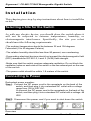
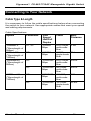
1
Manageable Gigabit Switch Signamax Connectivity Systems Manageable Gigabit Switch Model FO-065-7732AF U S E R ’ S G U I D E User’s Manual 1 Signamax Connectivity Systems Manageable Gigabit Switch Model FO-065-7732AF User’s Guide Signamax FO-065-7732AF Manageable Gigabit Switch Preface This manual describes how to install and use the Signamax FO-065-7732AF Manageable Gigabit Switch. This switch introduced here is designed to deliver full scalability with SNMP/RMON web-based management functions by providing: l l 24 x 100BaseFX fixed ports With fixed 2 x 1000BaseSX/LX ports For the fiber ports, it allows options of fiber type and wavelength at user’s discretion. This switch brings a simple answer to today’s complicated networking environments. To get the most out of this manual, you should have an understanding of Ethernet networking concepts. In this manual, you will find: Features on the Manageable Gigabit Switch l Illustrative LED functions l Installation instructions l Management Configuration l SNMP, DHCP, IGMP… l Specifications User’s Manual 1 Signamax FO-065-7732AF Manageable Gigabit Switch Table of Contents PREFACE 1 TABLE OF CONTENTS 2 PRODUCT OVERVIEW 4 SIGNAMAX FO-065-7732AF MANAGEABLE GIGABIT SWITCH4 PACKAGE CONTENTS 4 PRODUCT HIGHLIGHTS 5 Basic Features Management Support 5 5 FRONT PANEL DISPLAY PHYSICAL PORTS SWITCH MANAGEMENT 7 8 9 Administration console via RS-232 serial port Web-based browser interface External SNMP-based network management application 9 9 9 INSTALLATION 10 SELECTING A SITE FOR THE SWITCH CONNECTING TO POWER CONNECTING TO Y OUR NETWORK 10 10 11 Cable Type & Length Cabling 11 12 SWITCH M ANAGEMENT 13 MANAGEMENT A CCESS OVERVIEW A DMINISTRATION CONSOLE 13 14 Direct Access Modem Access 14 15 WEB MANAGEMENT SNMP-BASED NETWORK MANAGEMENT PROTOCOLS MANAGEMENT A RCHITECTURE 15 15 16 16 M ENU -DRIVEN CONSOLE M ANAGEMENT 17 LOGGING ON TO THE SWITCH 18 At the screen prompt 18 SWITCH MANAGEMENT SCREEN 19 Navigating Through the Console Interface 19 PERFORMING BASIC MANAGEMENT A CTIVITIES 20 Start with Selection Menu General Management Configurations LAN Port Configurations Console Port Configurations 20 21 22 25 PERFORMING A DVANCED MANAGEMENT A CTIVITIES Start with Selection Menu L2 Switching DataBase IP Networking Bridging 2 27 27 28 36 38 User’s Manual Signamax FO-065-7732AF Manageable Gigabit Switch Static Filtering MAC Address In-Filters Spanning Tree Functions SNMP Functions Other Protocols Port Trunking Port Mirroring QoS Setup Sending and Receiving Files LOGOUT SAVE SETTINGS RESTORE DEFAULT SETTINGS REBOOT WEB -BASED BROWSER M ANAGEMENT LOGGING ON TO THE SWITCH UNDERSTANDING THE BROWSER INTERFACE PERFORMING FILE A CTIVITIES Start with Selection Menu PERFORMING BASIC SETUP A CTIVITIES Start with Selection Menu LAN Port Configuration Console Port Configuration PERFORMING A DVANCED SETUP A CTIVITIES 40 41 42 46 48 49 50 51 58 59 59 60 60 61 61 62 64 64 65 65 67 70 72 Start with Selection Menu MAC Address Management Per Port Statistics Bridging Static MAC Filter IP Multicast Group Spanning Tree Perspective SNMP Other Protocols Port Trunking Port Mirroring QoS 72 72 76 77 78 81 82 84 86 89 90 91 SNMP & RMON M ANAGEMENT 97 OVERVIEW SNMP AGENT AND MIB-2 (RFC 1213) RMON MIB (RFC 1757) AND BRIDGE MIB (RFC 1493) RMON Groups Supported Bridge Groups Supported 97 97 98 98 99 SPECIFICATIONS 100 CONTACT INFORMATION 102 User’s Manual 3 Signamax FO-065-7732AF Manageable Gigabit Switch Product Overview Signamax FO-065-7732AF Manageable Gigabit Switch Front View Package Contents When you unpack the product package, you shall find the items listed below. Please inspect the contents, and report any apparent damage or missing items immediately to your authorized reseller. P P P P P 4 The Signamax FO-065-7732AF Manageable Gigabit Switch User’s Manual AC power cord RS232 cable Rackmount brackets with screws User’s Manual Signamax FO-065-7732AF Manageable Gigabit Switch Product Highlights Basic Features l l l l l l l l l l Fixed 24 x 100BaseFX ports With fixed 2 x 1000BaseSX/LX ports Full wire-speed forwarding rate Store-and-forward mechanism Back-pressure and IEEE 802.3x compliant flow control Supports 12K MAC addresses Provides 2MBytes memory buffer Front panel reset button Front panel port status LEDs Standard 19” rackmount size, one-unit-height Management Support VLAN l Port-based VLAN l 802.1Q tagged VLAN TRUNKING l MAC-based Trunking, up to three groups, two groups with a maximum of four 10/100TX/100FX ports each group, one group with a maximum of two 1000T/SX/LX ports l Load sharing based on source and destination MAC addresses PORT-SECURITY l Limit number of MAC addresses learned per port l Static MAC addresses stay in the filtering table PORT-MIRRORING l Port-mirroring provided through dedicated ports COS (IEEE802.1p Classification of Service) l 4-level transmission priorities: 4 queues per output port l Packet transmission scheduled using Weighted Round Robin (WRR) l User-defined weights l Classification of packet priority can be based on either a VLAN tag on packet or a user-definable port priority INTERNETWORKING PROTOCOLS l Bridging: 802.1D Spanning Tree 802.1p/Q – GARP/GVRP User’s Manual 5 Signamax FO-065-7732AF Manageable Gigabit Switch l l IP Multicast: IGMP Snooping Maximum of 128 VLANs and IP multicast sessions Rate Control NETWORK MANAGEMENT METHODS l Console port access via RS-232 cable l Telnet remote access l SNMP agent: MIB-2 (RFC1213) Bridge MIB (RFC1493) RMON MIB (RFC1757) – statistics, history, alarm and events VLAN MIB (802.1Q/RFC2674) Private MIB l Java applet-based MIB browser l Web browser support based on HTTP server and CGI parser l Kermit/TFTP software-upgrade capability 6 User’s Manual Signamax FO-065-7732AF Manageable Gigabit Switch Front Panel Display • POWER This LED comes on when the switch is properly connected to power and turned on. ‚ Port Status LEDs The LEDs are located at the left side of the switch, displaying status for each respective port. Please refer to the following table for more details. LED State Indication On A valid network connection established. LNK stands for LINK. Flashing Transmitting or receiving data. On Connection in full duplex mode. FDX stands for FULL-DUPLEX. Flashing Collision occurred. COL stands for COLLISION. Off Connection in half-duplex mode. LNK/ACT FDX/COL User’s Manual ACT stands for ACTIVITY. 7 Signamax FO-065-7732AF Manageable Gigabit Switch Physical Ports The Manageable Gigabit Switch provides: l Fixed 24 x 100BaseFX ports l With fixed 2 x 1000BaseSX/LX ports CONNECTIVITY l SC connectors on 1000SX/LX ports l ST or SC connectors on 100FX ports MODE SELECTION • 100BaseFX full-duplex mode • 100BaseFX half-duplex mode • 1000BaseSX/LX full-duplex mode • 1000BaseSX/LX half-duplex mode • Auto-negotiating mode 8 User’s Manual Signamax FO-065-7732AF Manageable Gigabit Switch Switch Management Administration console via RS-232 serial port The switch provides an onboard serial port, which allows the switch to be configured via a directly connected terminal or a Telnet session. Web-based browser interface The switch also boasts a point-and-click browser-based interface that lets users access full switch configuration and functionality from a Netscape or Internet Explorer browser. External SNMP-based network management application The switch can also be configured via SNMP. User’s Manual 9 Signamax FO-065-7732AF Manageable Gigabit Switch Installation This chapter gives step-by-step instructions about how to install the switch: Selecting a Site for the Switch As with any electric device, you should place the switch where it will not be subjected to extreme temperatures, humidity, or electromagnetic interference. Specifically, the site you select should meet the following requirements: -The ambient temperature should be between 32 and 104 degrees Fahrenheit (0 to 40 degrees Celsius). -The relative humidity should be less than 90 percent, non-condensing. -Surrounding electrical devices should not exceed the electromagnetic field (RFC) standards for IEC 801-3, Level 2 (3V/M) field strength. -Make sure that the switch receives adequate ventilation. Do not block the ventilation holes on each side of the switch or the fan exhaust port on the rear of the switch. -The power outlet should be within 1.8 meters of the switch. Connecting to Power Redundant power supplies: Step 1: Connect the AC power cord to the receptacle on the back of the switch, and then plug it into a standard AC outlet with a voltage range from 100 to 240 VAC. Or connect the DC power cord to the receptacle on the back of the switch, and then plug it into a standard DC outlet with a voltage -48 VDC. Step 2: Disconnect the power cord if you want to shut down the switch. Rear view 10 User’s Manual Signamax FO-065-7732AF Manageable Gigabit Switch Connecting to Your Network Cable Type & Length It is necessary to follow the cable specifications below when connecting the switch to your network. Use appropriate cables that meet your speed and cabling requirements. Cable Specifications Speed Connector Port Speed Half/Full Duplex Cable Max. Distance 100BaseFX (*Wavelength of 850nm) 100BaseFX (*Wavelength of 1300nm) 1000BaseSX (*Wavelength of 850nm) ST, SC 100/200 Mbps 62.5/125µm multi-mode fiber 2 km SC 100/200 Mbps 10/125µm 75 km single-mode fiber SC 1000/2000 Mbps 62.5/125µm multi-mode fiber 220 m SC 1000/2000 Mbps 50/125µm multi-mode fiber 550 m SC 1000/2000 Mbps 62.5/125µm multi-mode fiber 550 m SC 1000/2000 Mbps 10/125µm 20 km single-mode fiber 1000BaseLX (*Wavelength of 1300nm) User’s Manual 11 Signamax FO-065-7732AF Manageable Gigabit Switch Cabling Step 1: First, ensure the power of the switch and end devices is turned off. <Note> Always ensure that the power is off before any installation. Step 2: Prepare cable with corresponding connectors for each type of port in use. Step 3: Consult Cable Specifications Table on previous page for cabling requirements based on connectors and speed. Step 4: Connect one end of the cable to the switch and the other end to a desired device. Step 5: Once the connections between two end devices are made succes sfully, turn on the power and the switch is operational. 12 User’s Manual Signamax FO-065-7732AF Manageable Gigabit Switch Switch Management This chapter explains the methods that you can use to configure management access to the switch. It describes the types of management applications and the communication and management protocols that deliver data between your management device (workstation or personal computer) and the system. It also contains information about port connection options. This chapter covers the following topics: • • • • • • • Management Access Overview Key Concepts Key Guidelines for Implementation Administration Console Access Web Management Access SNMP Access Standards, Protocols, and Related Reading Management Access Overview The switch gives you the flexibility to access and manage the switch using any or all of the following methods. The administration console and web browser interface support are embedded in the switch software and are available for immediate use. User’s Manual 13 Signamax FO-065-7732AF Manageable Gigabit Switch Administration Console The administration console is an internal, character-oriented, menu-driven user interface for performing system administration such as displaying statistics or changing option settings. Using this method, you can view the administration console from a terminal, personal computer, Apple Macintosh, or workstation connected to the switch’s console port. There are two ways to use this management method: direct access or modem access. The following sections describe these methods. Direct Access Direct access to the administration console is achieved by directly connecting a terminal or a PC equipped with a terminal-emulation program (such as HyperTerminal) to the switch console port. When using the management method, configure the terminal-emulation program to use the following parameters (you can change these settings after login): [DEFAULT PARAMETERS] ♦ ♦ ♦ ♦ 115,200bps 8 data bits No parity 1 stop bit This management method is often preferred because you can remain connected and monitor the system during system reboots. Also, certain error messages are sent to the serial port, regardless of the interface through which the associated action was initiated. A Macintosh or PC attachment can use any terminal-emulation program for connecting to the terminal serial port. A workstation attachment under UNIX can use an emulator such as TIP. 14 User’s Manual Signamax FO-065-7732AF Manageable Gigabit Switch Modem Access You can access the switch’s administration console from a PC or Macintosh using an external modem attached to the console port. The switch management program provides Console Port screen, accessible from the Basic Management screen, that lets you configure parameters for modem access. When you have configured the external modem from the administration console, the switch transmits characters that you have entered as output on the modem port. The switch echoes characters that it receives as input on the modem port to the current administration console session. The console appears to be directly connected to the external modem. Web Management The switch provides a browser interface that lets you configure and manage the switch remotely. After you set up your IP address for the switch, you can access the switch’s web interface applications directly in your web browser by entering the IP address of the switch. You can then use your web browser to list and manage switch configuration parameters from one central location, just as if you were directly connected to the switch’s console port. Web Management requires either Microsoft Internet Explorer 4.01 or later or Netscape Navigator 4.03 or later. SNMP-Based Network Management You can use an external SNMP-based application to configure and manage the switch. This management method requires the SNMP agent on the switch and the SNMP Network Management Station to use the same community string. This management method, in fact, uses two community strings: the get community string and the set community string. If the SNMP Network management station only knows the set community string, it can read and write to the MIBs. However, if it only knows the get community string, it can User’s Manual 15 Signamax FO-065-7732AF Manageable Gigabit Switch only read MIBs. The default get and set community strings for the switch are public. Protocols The switch supports the following protocols: VIRTUAL TERMINAL PROTOCOLS, SUCH AS TELNET A virtual terminal protocol is a software program, such as Telnet, that allows you to establish a management session from a Macintosh, a PC, or a UNIX workstation. Because Telnet runs over TCP/IP, you must have at least one IP address configured on the switch before you can establish access to it with a virtual terminal protocol. <Note> Terminal emulation is different from a virtual terminal protocol in that you must connect a terminal directly to the console port. SIMPLE NETWORK MANAGEMENT PROTOCOL (SNMP) SNMP is the standard management protocol for multivendor IP networks. SNMP supports transaction-based queries that allow the protocol to format messages and to transmit information between reporting devices and data-collection programs. SNMP runs on top of the User Datagram Protocol (UDP), offering a connectionless-mode service. Management Architecture All of the management application modules use the same Messaging Application Programming Interface (MAPI). By unifying management methods with a single MAPI, configuration parameters set using one method (e.g. console port) are immediately displayed the other management methods (e.g. SNMP agent of web browser). The management architecture of the switch adheres to the IEEE open standard. This compliance assures customers that the switch is compatible with, and will interoperate with other solutions that adhere to the same open standard. 16 User’s Manual Signamax FO-065-7732AF Manageable Gigabit Switch M e n u -Driven Console Management The switch provides a menu-driven console interface for configuration purposes. The switch can be configured either locally through its RS-232 port or remotely via a Telnet session. For the later, you must specify an IP address for the switch first. This chapter describes how to configure the switch using its menu-driven console. * For initial IP settings, you must configure the switch through its RS232 port. User’s Manual 17 Signamax FO-065-7732AF Manageable Gigabit Switch Logging on to the switch At the screen prompt Login: Password: LOGIN NAME Enter the console interface factory default console name admin. PASSWORD Enter the factory default password (no password, press <Enter> directly). Or enter a user-defined password if you followed the instructions later and changed the factory default password. Factory Default Password: no password, press <Enter> directly. <Note> 18 Only one console and three telnet users can log on to the switch concurrently. However, it is not recommended that multiple users modify the configuration at the same time. User’s Manual Signamax FO-065-7732AF Manageable Gigabit Switch Switch Management Screen BASIC MANAGEMENT Basic management activities. ADVANCED MANAGEMENT Advanced management activities. LOGOUT Highlight this option and press Enter to log out. SAVE SETTINGS Highlight this option and press Enter to save the current settings and remain in the configuration program. RESTORE DEFAULT SETTINGS Highlight this option and press Enter to restore the factory default settings. REBOOT Highlight this option and press Enter to reboot. Navigating Through the Console Interface The console interface consists of a series of menu boxes. Each menu box has several options, which are listed vertically. Move the highlight to select an option as you wish; press the Enter key to activate that option. Press this key… To Up Arrow or K* Move the highlight one line up in a menu box Down Arrow or J* Move the highlight one line down in a menu box Tab Move the highlight between screens Enter Select the highlighted option Esc Move to a previous menu <Note> * Remember to release the <Caps Lock> key if you press <K> or <J> and cannot move the highlight on the screen. User’s Manual 19 Signamax FO-065-7732AF Manageable Gigabit Switch Performing Basic Management Activities Basic management activities consist of General, LAN Port, and Console Port tasks. Start with Selection Menu Step 1: Highlight [Basic Management] from [Switch Management] screen and press <Enter>. The [Basic Management] screen appears: Step 2: Highlight a desired option and press <Enter>. Or press <Esc> to exit. 20 User’s Manual Signamax FO-065-7732AF Manageable Gigabit Switch General Management Configurations Step 1: Highlight [General] from [Basic Management] screen and press <Enter>. System Name Step 2: System Name is highlighted. Press <Enter> if you want to change it. Location Step 3: Move to highlight Location and press <Enter> if you want to change it. admin Password Step 4: Move to highlight admin Password and press <Enter> if you want to change it. guest Password Step 5: Move to highlight guest Password and press <Enter> if you want to change it. Statistics Collection Step 6: Move to highlight Statistics Collection and press <Enter> if you want to change it, Disabled or Enabled. User’s Manual 21 Signamax FO-065-7732AF Manageable Gigabit Switch Reboot-On-Error Step 7: Move to highlight Reboot-On-Error and press <Enter> if you want to change it, Disabled or Enabled. Remote Telnet Login Step 8: Move to highlight Remote Telnet Login and press <Enter> if you want to change it, Disabled or Enabled. Remote HTTP Login Step 9: Move to highlight Remote HTTP Login and press <Enter> if you want to change it, Disabled or Enabled. Return to Basic Management Step 10: Press <Esc> to return to [Basic Management] screen when completed. LAN Port Configurations Step 1: 22 Highlight [LAN Port] from [Basic Management] screen and press <Enter>. User’s Manual Signamax FO-065-7732AF Manageable Gigabit Switch SPEED & FLOW CONTROL Step 2: Speed & Flow Control is highlighted. Press <Enter> if you want to set speed or flow control on port. Step 3: Highlight All (10/100M or 1000M) Ports and press <Enter> to configure at one time. Otherwise, move to highlight each port and press <Enter> to configure individually. Step 4: Port Setting Options screen appears. Highlight Speed & Flow Control and press <Enter>. Line Speed Step 5: For Line Speed, move to highlight a desired setting from Speed Options and press <Enter>. <Note> In the Speed Options, Auto denotes auto negotiation on speed and duplex mode, HD denotes half-duplex, and FD denotes full-duplex. Step 6: Press <Esc> to previous screen. Highlight Flow Control and press <Enter> Flow Control Step 7: For Flow Control, move to highlight a desired setting from the Flow Cntl Options and press <Enter>. User’s Manual 23 Signamax FO-065-7732AF Manageable Gigabit Switch Step 8: Press <Esc> to a previous screen as shown in Step 3. PHYSICAL PORT ADDRESS Step 9: Press <Esc> to a previous screen as shown in Step 1. Step 10: Move to highlight Physical Address to view physical port address. Return to Basic Management Step 11: Press <Esc> to return to [Basic Management] screen when completed. 24 User’s Manual Signamax FO-065-7732AF Manageable Gigabit Switch Console Port Configurations Step 1: Move to highlight [Console Port] from [Basic Management] screen. Baud Rate Step 2: Baud Rate is highlighted. Press <Enter> if you want to change the current console baud rate. Flow Control Step 3: Move to highlight Flow Control and press <Enter> if you want to change the current flow control method. Modem Control Step 4: Move to highlight Modem Control and press <Enter> to decide a console modem connection, Disabled or Enabled. Modem Setup String Step 5: When a modem connection is enabled, move to highlight Modem Setup String and press <Enter>. Decide whether you want to use Default or Custom Setup String. <Note> Default Setup String configures the modem to auto answer. It works for all Hayes compatible modems. User’s Manual 25 Signamax FO-065-7732AF Manageable Gigabit Switch SLIP Step 6: <Note> Move to highlight SLIP and press <Enter> if you want to change it, Disabled or Enabled. If you enable SLIP, a message tells you that the cons ole port becomes accessible only through the SLIP protocol after you logout from the current console screen. SLIP Address Step 7: Move to highlight SLIP Address and press <Enter> if you want to set it. SLIP Subnet Mask Step 8: When SLIP IP address is entered, move to highlight SLIP Subnet Mask and press <Enter>. Enter a suitable subnet mask. <Note> Step 9: 26 You must enter a SLIP address before you can enter a SLIP subnet mask. Return to Basic Management Press <Esc> to return to [Basic Management] screen when completed. User’s Manual Signamax FO-065-7732AF Manageable Gigabit Switch Performing Advanced Management Activities Advanced management activities consist of L2 Switching DataBase / IP Networking / Bridging / Static Filtering / Spanning Tree / SNMP / Other Protocols / Port Trunking / Port Mirroring / QoS Setup / File Transfer. Start with Selection Menu Step 1: Highlight [Advanced Management] from [Switch Management] screen and press <Enter>. The [Advanced Management] screen appears: Step 2: Move to highlight a desired option and press <Enter>. Or press <Esc> to exit. L2 SWITCHING DATABASE View and change VLAN, MAC address, IP multicast group, and port perspectives. IP NETWORKING View and change IP settings. BRIDGING View and change the aging period for a MAC address and the flood limit for all ports. STATIC FILTERING View / add / delete / search all source or destination MAC addresses to be filtered. SPANNING TREE View and change spanning tree configurations, ports states, path costs, and port priorities. SNMP View and change the SNMP configuration. OTHER PROTOCOLS View and change GVRP and IGMP settings. PORT TRUNKING Assign a range of ports to trunking groups. User’s Manual 27 Signamax FO-065-7732AF Manageable Gigabit Switch PORT MIRRORING Mirror one port to another. QOS SETUP Specify Quality of Service parameter. FILE TRANSFER Send files using the TFTP or Kermit protocol. L2 Switching DataBase Highlight [L2 Switching DataBase] from [Advanced Management] screen and press <Enter>. 28 User’s Manual Signamax FO-065-7732AF Manageable Gigabit Switch User’s Manual 29 Signamax FO-065-7732AF Manageable Gigabit Switch VLAN & PVID PERSPECTIVE There are three types of private VLAN ports: promiscuous, isolated, and community. 1. A promiscuous port communicate with all other private VLAN ports and is the port you use to communicate with routers, servers, and administrative workstations. 2. An isolated port has complete Layer 2 separation from other ports within the same private VLAN with the exception of the promiscuous port. 3. Community ports communicate among themselves and with their promiscuous ports. These ports are isolated at Layer 2 from all other ports in other communities or isolated ports within their private VLAN. 4. Primary VLAN conveys incoming traffic from the promiscuous port to all other promiscuous, isolated, and community ports. 5. Isolated VLAN used by isolated ports to communicate to the promiscuous ports. 6. Community VLAN used by a group of community ports to communicate among themselves and transmit traffic to outside the group via the designated promiscuous port. For example: VLAN ID Promiscuous port Isolated port Community ports Primary VLAN 2 2 3,4 5,6,7,8 Isolated VLAN 3 2 3 Isolated VLAN 4 2 4 Community VLAN 5 2 5,6 Community VLAN 6 2 7,8 1. Create the primary VLAN and bind the promiscuous port, isolated port(s), and community ports to the primary VLAN. 2. Create the isolated VLAN(s) and bind the promiscuous port and isolated port(s) to the isolated VLAN(s). 3. Create the community VLAN(s) and bind the promiscuous port and community ports to the community VLAN(s). 4. Associate the primary VLAN to the promiscuous port. 5. Associate the isolated VLAN(s) to the isolated port(s). 6. Associate the community ports to the community VLAN(s). Step 1: 30 Highlight the VLAN & PVID Perspective and press <Enter>. User’s Manual Signamax FO-065-7732AF Manageable Gigabit Switch Step 2: Highlight the VLAN Settings and press <Enter> to view VLAN info of the default VLAN or if you want to obtain a VLAN perspective instead of the default VLAN. <Note> Default VLAN: The IEEE802.1Q standard defines VLAN ID #1 as the default VLAN. The default VLAN includes all the ports as the factory default. The default VLAN’s egress rule restricts the ports to be all untagged, so it can, by default, be easily used as a simple 802.1D bridging domain. The default VLAN’s domain shrinks as untagged ports are defined in other VLANs. Create VLAN Step 3: Press <Shift> and [+] on keypad to enter New VLAN Settings . Enter new VLAN ID and VLAN name. <Note> “Remote” is appended to the VLAN ID automatically if the VLAN is learned from a remote switch. Add New Switch Ports Step 4: Press <Esc> and appears the following screen. Press <Shift> and [+] to add new switch ports to the newly created VLAN. Step 5: Move to highlight a suitable option from Port Options and press <Enter>, e.g. Untagged Ports. Step 6: From Select Untagged Ports , press <Enter> to select All Ports or move to highlight each port individually and press <Enter>. Similar procedure when you select Tagged Ports and Forbidden Ports in Step 4. <Note> If you added untagged ports and want to now add tagged ports or forbidden ports, or vice versa, repeat Step 4 and Step 5. Step 7: Press <Esc> to a previous screen as shown in Step 1. Delete VLAN Step 8: Delete VLAN: highlight a VLAN ID and press [-] to delete it. Note that you cannot delete the default VLAN. Step 9: Press <Esc> to a previous screen as shown in Step 1 when completed with deleting a VLAN. VLAN Info Step 10: Highlight an existing VLAN and press <Enter> to view VLAN information. Step 11: Move to highlight VLAN Activities and press <Enter> to view or search activity information. User’s Manual 31 Signamax FO-065-7732AF Manageable Gigabit Switch Step 12: Return to Step 9. Move to highlight VLAN Settings and press <Enter>. The screen appears as shown in Step 3 for adding or deleting switch ports. Step 13: Highlight the VLAN & PVID Perspective and press <Enter>. Step 14: Highlight the PVID Settings and press <Enter> to apply PVIDs to the ports. Step 15: Highlight the port and press <Enter> to enter PVID to the port. 32 User’s Manual Signamax FO-065-7732AF Manageable Gigabit Switch IP MULTICAST GROUP PERSPECTIVE Step 1: Move to highlight [Other Protocols] from [Advanced Management] screen and press <Enter>. Step 2: Move to highlight IGMP and press <Enter> to change the Disable to Passive or Active. Step 3: Move to highlight [IP Multicast Group Perspective] from [L2 Switching DataBase] screen and press <Enter>. Step 4: Move to highlight an address to view information associated with this IP multicast group. User’s Manual 33 Signamax FO-065-7732AF Manageable Gigabit Switch MAC ADDRESS PERSPECTIVE Step 1: Move to highlight [MAC Address Perspective] from [L2 Switching DataBase] screen and press <Enter>. Step 2: 34 Enter a MAC address to view characteristics information, corresponding VLANs, and corresponding ports in the switching database. User’s Manual Signamax FO-065-7732AF Manageable Gigabit Switch PORT PERSPECTIVE Step 1: Move to highlight [Port Perspective] from [L2 Switching DataBase] screen and press <Enter>. You can view VLAN activities and RMON statistics here. Per Port VLAN Activities Step 2: Per Port VLAN Activities is highlighted. Press <Enter>. Step 3: Move to highlight a port and press <Enter>. E.g. select Port 1 to view corresponding VLAN Activities. Step 4: View or search by MAC address individually. Step 5: Press <Esc> to return to a previous screen as shown in Step 1. Per Port Statistics Step 6: Move to highlight Per Port Statistics and press <Enter>. Step 7: Move to highlight a port and press <Enter>. Press <R> to reset counter for this port. Per Port MAC Limit Step 8: Move to highlight Per Port MAC Limit and press <Enter>. Step 9: Move to highlight a port and press <Enter>. User’s Manual 35 Signamax FO-065-7732AF Manageable Gigabit Switch IP Networking Move to highlight [IP Networking] from [Advanced Management] screen and press <Enter>. IP & RIP SETTINGS Step 1: Highlight [IP & RIP Settings] from [IP Networking] and press <Enter>. 36 User’s Manual Signamax FO-065-7732AF Manageable Gigabit Switch Initial IP Settings Step 2: Move to highlight IP Address and press <Enter>. User’s Manual 37 Signamax FO-065-7732AF Manageable Gigabit Switch Step 3: Type an IP address and press <Enter> Step 4: Press <Esc> until you return to [Switch Management] screen. Make sure you save the settings before you log out Bridging Move to highlight [Bridging] from [Advanced Management] screen, and press <Enter>. AGING TIME Step 1: Move to highlight Aging Time and press <Enter>. Aging Options Step 2: Set Aging Time is highlighted. Press <Enter>. Enter a decimal number as bridge aging period in seconds. Step 3: Otherwise, you may move to highlight No Aging, and press <Enter>. FLOOD LIMIT FOR ALL PORTS Step 1: Move to highlight [Flood Limit for All ports] and press <Enter>. Flooding Options Step 2: Set Flood Limit is highlighted. Pr ess <Enter>. 38 User’s Manual Signamax FO-065-7732AF Manageable Gigabit Switch Enter a decimal number as flood limit in packets per second. Step 3: Otherwise, you may move to highlight Unlimited, and press <Enter>. BROADCAST LIMIT Step 1: Move to highlight [Broadcast Limit] and press <Enter>. Broadcasting Options Step 2: Set Broadcast Limit is highlighted. Press <Enter>. Enter a decimal number as broadcast limit in packets per second. Step 3: Otherwise, you may move to highlight Unlimited, and press <Enter>. MULTICAST LIMIT Step 1: Move to highlight [Multicast Limit] and press <Enter>. Multicasting Options Step 2: Unlimited is highlighted. Press <Enter>. Step 3: Otherwise, you may move to highlight Set Multicast Limit. Enter a decimal number as multicast limit in packets per second and press <Enter>. User’s Manual 39 Signamax FO-065-7732AF Manageable Gigabit Switch Static Filtering Move to highlight [Static Filtering] from [Advanced Management] screen, and press <Enter>. 40 User’s Manual Signamax FO-065-7732AF Manageable Gigabit Switch SOURCE/DESTINATION MAC ADDRESS OUT-FILTERS Step 1: Move to highlight source MAC addresses or destination MAC addresses for static filtering, and press <Enter>. Add/Delete/Search Step 2: Press <Shift> and [+] on keypad to add a specific MAC address to be filtered. Press [-] to delete a specific MAC address from being filtered. Press <S> to search through current list of MAC addresses in the static filtering database. The static filtering database maximum capacity is 128. * No precautionary message appears before you delete a specific MAC address from being filtered. * Be sure you want to delete it before doing so. MAC Address In-Filters Move to highlight [Static Filtering] from [Advanced Management] screen, and press <Enter>. MAC ADDRESS IN-FILTERS Step 1: Move to highlight MAC addresses In-Filters and press <Enter>. User’s Manual 41 Signamax FO-065-7732AF Manageable Gigabit Switch Add/Delete/Search Step 2: Press <Shift> and [+] on keypad to add a specific MAC address to be filtered. Press [-] to delete a specific MAC address from being filtered. Press <S> to search through current list of MAC addresses in the static filtering database. The static filtering database maximum capacity is 128. * No precautionary message appears before you delete a specific MAC address from being filtered. * Be sure you want to delete it before doing so. Spanning Tree Functions Move to highlight [Spanning Tree] from [Advanced Management] screen, and press <Enter>. 42 User’s Manual Signamax FO-065-7732AF Manageable Gigabit Switch SPANNING TREE CONFIGURATIONS Step 1: Move to highlight [Spanning Tree Configurations] if you want to change Spanning Tree Protocol Configurations. Spanning Tree Protocol Step 2: Press <Enter> to enter Spanning Tree Options . Decide to have it Disabled or Enabled. Bridge Priority Step 3: Move to highlight Bridge Priority and press <Enter>. Type a decimal number for the bridge priority and press <Enter>. Hello Time (sec) Step 4: Move to highlight Hello Time and press <Enter>. Type a decimal number for the hello time and press <Enter>. Max Age (sec) Step 5: Move to highlight Max Age and press <Enter>. Type a decimal number for the max age. Forward Delay (sec) Step 6: Move to highlight Forward Delay and press <Enter>. Type a decimal number for the forward delay. User’s Manual 43 Signamax FO-065-7732AF Manageable Gigabit Switch SPANNING TREE PORT STATES Step 1: Move to highlight [Spanning Tree Port States] if you want to change per port administration status, and press <Enter>. Step 2: Move to highlight a port if you want to change its administration status, and press <Enter>. ‘Disabled (Link Down)’ denotes Admin Status Up without a link. ‘Forwarding’ denotes Admin Status Up with a link. ‘Admin Status Down’ denotes no TX/RX transmission allowed ‘Admin Status Up ’ denotes TX/RX transmission allowed. 44 User’s Manual Signamax FO-065-7732AF Manageable Gigabit Switch SPANNING TREE PATH COSTS Step 1: To change the path cost, move to highlight [Spanning Tree Path Costs] and press <Enter>. Step 2: Move to highlight All Ports or each port individually, and press <Enter>. For new path cost, type a decimal number and press <Enter>. User’s Manual 45 Signamax FO-065-7732AF Manageable Gigabit Switch SPANNING TREE PORT PRIORITIES Step 1: To change the priority level per port, move to highlight [Spanning Tree Port Priorities] and press <Enter>. Step 2: Move to highlight All Ports or each port individually, and press <Enter>. For new priority value, ty pe a decimal number from 0-255, and press <Enter>. A low value gives the port a greater likelihood of becoming a Root port. SNMP Functions Move to highlight [SNMP] from [Advanced Management] screen, and press <Enter>. SNMP Options Step 1: Move to highlight SNMP and press <Enter>. Decide to have it Disabled or Enabled. Get Community Name Step 2: Move to highlight Get Community Name and press <Enter>. Enter text and press <Enter>. Set Community Name Step 3: Move to highlight Set Community Name and press <Enter>. 46 User’s Manual Signamax FO-065-7732AF Manageable Gigabit Switch Enter text and press <Enter>. Trap Community Name Step 4: Move to highlight Trap Community Name 1 and press <Enter>. Enter text and press <Enter>. Repeat to specify up to three more trap community names. Trap Host IP Address Step 5: Move to highlight Trap Host 1 IP Address and press <Enter>. Type an IP address for trap host 1 and press <Enter> Repeat to specify up to three more trap host IP addresses Cold Start Trap Step 6: Move to highlight Cold Start Trap and press <Enter>. Decide to have it Disabled or Enabled. Warm Start Trap Step 7: Move to highlight Warm Start Trap and press <Enter>. Decide to have it Disabled or Enabled. Link Down Trap Step 8: Move to highlight Link Down Trap and press <Enter>. Decide to have it Disabled or Enabled. Link Up Trap Step 9: Move to highlight Link Up Trap and press <Enter>. Decide to have it Disabled or Enabled. Authentication Failure Trap Step 10: Move to highlight Authentication Failure Trap and press <Enter>. Decide to have it Disabled or Enabled. Rising Alarm Trap Step 11: Move to highlight Rising Alarm Trap and press <Enter>. Decide to have it Disabled or Enabled. Falling Alarm Trap Step 12: Move to highlight Falling Alarm Trap and press <Enter>. Decide to have it Disabled or Enabled. Topology Change Trap Step 13: Move to highlight Topology Change Trap and press <Enter>. Decide to have it Disabled or Enabled. User’s Manual 47 Signamax FO-065-7732AF Manageable Gigabit Switch Other Protocols Move to highlight [Other Protocols] from [Advanced Management] screen, and press <Enter>. GVRP Step 1: Move to highlight GVRP and press <Enter>. Step 2: Decide to have it Disabled or Enabled. IGMP Step 1: Move to highlight IGMP and press <Enter>. Step 2: Decide to have it Disabled or set in either Passive or Active mode. 48 User’s Manual Signamax FO-065-7732AF Manageable Gigabit Switch Port Trunking Move to highlight [Port Trunking] from [Advanced Management] screen, and press <Enter>. Select Range Step 1: Move to highlight a trunk group to which you want to assign ports, and press <Enter> to enter Select Range. Step 2: Move to highlight a port range, Port 1-24 or Port 25-26. Select Trunk Ports Step 3: E.g. Port 1-24 is highlighted. Move and press <Enter> to select a trunk port. You can select a maximum of four ports for this Trunk group. Step 4: E.g. Port 25-26 is highlighted. Move and press <Enter> to select a trunk port. You can select a maximum of two ports for this Trunk group. Step 5: Press <Esc> when completed with selecting ports User’s Manual 49 Signamax FO-065-7732AF Manageable Gigabit Switch Port Mirroring Move to highlight [Port Mirroring] from [Advanced Management] screen, and press <Enter>. Mirror To Step 1: Press <Enter> to enter Mirror To Options , listing the ports that can be mirrored to. Step 2: Move to highlight the port you want to mirror to and press <Enter>. Mirror From Step 3: Press <Enter> to enter Mirror From Options, listing the ports that can be mirrored from. Step 4: Move to highlight the port you want to mirror from and press <Enter>. Mirror Mode Step 5: Move to select Mirror Mode . From Mode Options , decide whether the port to be mirrored from will be receiving or transmitting. Step 6: Press <Esc> when completed. 50 User’s Manual Signamax FO-065-7732AF Manageable Gigabit Switch QoS Setup Move to highlight [QoS Setup] from [Advanced Management] screen, and press <Enter>. User’s Manual 51 Signamax FO-065-7732AF Manageable Gigabit Switch Global Setting Step 1: Move to highlight Global Setting and press <Enter>. Step 2: Move to highlight QoS Status and press <Enter>. Move to highlight to enable or disable QoS Status and press <Enter>. Step 3: Move to highlight Diffserv Expedite Forwarding and press <Enter>. Move to highlight to enable or disable Diffserv Expedite Forwarding and press <Enter>. Step 4: Move to highlight ToS/VLAN and press <Enter>. Highlight the desired setting then press <Enter>. Step 5: Move to highlight ToS for Xmit and press <Enter>. Highlight the desired setting then press <Enter>. Step 6: Move to highlight ToS for Drop and press <Enter>. Highlight the desired setting then press <Enter>. Step 7: Move to highlight WRED Drop Priority Setting and press <Enter>. Move to highlight to Low Drop Percentage or High Drop Percentage and press <Enter>. Step 8: Press <Esc> when completed Logical Port Step 1: Move to highlight Logical Port and press <Enter>. 52 User’s Manual Signamax FO-065-7732AF Manageable Gigabit Switch Step 2: Move to highlight User Define Port, Well-Known Port, or Range Port and press <Enter>. Step 3: Move to highlight the appropriate port and press <Enter>. Step 4: Press <Esc> when completed VLAN Step 1: Step 2: Move to highlight VLAN and press <Enter> to specify the QoS VLAN priority. Move to highlight Drop Priority or Transmit Priority and press <Enter>. Step 3: Press <Esc> when completed User’s Manual 53 Signamax FO-065-7732AF Manageable Gigabit Switch ToS Step 1: Step 2: Move to highlight TOS and press <Enter> to specify the ToS priority. Move to highlight Drop Priority or Transmit Priority and press <Enter>. Step 3: Press <Esc> when completed 54 User’s Manual Signamax FO-065-7732AF Manageable Gigabit Switch Profile Step 1: Step 2: Move to highlight Profile and press <Enter> to select a QoS profile. Move to highlight Megabit Profile or Gigabit Profile and press <Enter>. Step 3: Press <Esc> when completed User’s Manual 55 Signamax FO-065-7732AF Manageable Gigabit Switch Port Configuration Step 1: Move to highlight Port Configuration and press <Enter> to spec ify the port configuration parameters. Step 2: Move to highlight Active Profile, Fixed Drop Priority, or Fixed Transmit Priority and press <Enter>. Step 3: Press <Esc> when completed 56 User’s Manual Signamax FO-065-7732AF Manageable Gigabit Switch Rate Control Step 1: Move to highlight Rate Control and press <Enter> to specify rate control parameters. Step 2: Move to highlight Rate Control, or Port Number and press <Enter>. Step 3: Press <Esc> when completed. User’s Manual 57 Signamax FO-065-7732AF Manageable Gigabit Switch Sending and Receiving Files Move to highlight [File Transfer] from [Advanced Management] screen, and press <Enter>. If you access the administration console by connecting an RS232 cable directly to the console port at the back of the switch, you will see a [File Transfer] screen. RECEIVE FILE VIA TFTP Step 1: Move to highlight Receive File Via TFTP and press <Enter>. Step 2: Type the name of the file you intend to receive and press <Enter>. Step 3: Move to highlight IP Address and press <Enter>. Type the IP address from where the file will be obtained. Step 4: Press <Esc> when completed. Step 5: A dialog box appears to ask if you want to transfer file now. Highlight [Yes] and press <Enter> to start file transfer. Otherwise, move to highlight [No] and press <Enter> to deny it. Step 6: Press <Esc> to a previous screen. 58 User’s Manual Signamax FO-065-7732AF Manageable Gigabit Switch SEND FILE VIA TFTP Step 1: In [File Transfer] screen, move to highlight Send File Via TFTP and press <Enter>. Step 2: If the default File Type is not the one you intend to send, press <Enter>. Select the file type you intend to send and press <Enter>. Step 3: Repeat Step 3-5. RECEIVE FILE VIA KERMIT Step 1: In [File Transfer] screen obtained via console port, move to highlight Receive File Via Kermit and press <Enter>. Step 2: A dialog box appears to ask if you want to transfer file now. Move to highlight [Yes] and press <Enter> to start file transfer. Otherwise, highlight [No] and press <Enter> to deny it. Step 3: Press <Esc> to a previous screen. SEND FILE VIA KERMIT Step 1: In [File Transfer] screen obtained via console port, move to highlight Send File Via Kermit and press <Enter>. Step 2: Move to highlight a file type you intend to send and press <Enter>. Step 3: A dialog box appears to ask if you want to transfer file now. Move to highlight [Yes] and press <Enter> to start file transfer. Otherwise, highlight [No] and press <Enter> to deny it. Step 4: Press <Esc> to a previous screen. Logout To log out, highlight [Logout] from [Switch Management] screen and press <Enter>. Please remember to save settings you have changed before you log out. Save Settings To save the current settings and remain in the configuration program, highlight [Save Settings] from [Switch Management] and press <Enter>. User’s Manual 59 Signamax FO-065-7732AF Manageable Gigabit Switch Restore Default Settings To restore the factory default settings, highlight [Restore Default Settings] from [Switch Management] and press <Enter>. The switch will be rebooted after confirming Yes as to restore the default settings. Reboot To reboot the switch, highlight [Reboot] from [Switch Management] and press <Enter>. 60 User’s Manual Signamax FO-065-7732AF Manageable Gigabit Switch W e b -B a s e d B r o w s e r M a n a g e m e n t The switch provides a web-based browser interface for configuring and managing the switch. This interface allows you to access the switch using a preferred web browser. This chapter describes how to configure the switch using its web-based browser interface. Logging on to the switch SWITCH IP ADDRESS In your web browser, specify the IP address of the switch. LOGIN ID Enter the factory default login ID: admin. User’s Manual 61 Signamax FO-065-7732AF Manageable Gigabit Switch PASSWORD Enter the factory default password (no password, press Enter directly). Otherwise, enter a user-defined password if you followed the instructions later and changed the factory default password. Understanding the Browser Interface The web browser interface provides three point-and-click buttons at the upper field of the screen for configuring and managing the switch. In addition, you can click any port on the switch image to view the switch’s current speed, duplex, and activity status. The Basic Setup/General parameters appear at the lower field of the screen. These parameters can also be displayed by clicking Basic Setup button and select General in sub-menu. 62 User’s Manual Signamax FO-065-7732AF Manageable Gigabit Switch FILE Save settings configured in the browser interface / download upgraded software via TFTP / reboot the switch / logout of the browser interface. BASIC SETUP Perform general, LAN port, and console port activities. ADVANCED SETUP Perform MAC Address Management / Per Port Statistics / Bridging / Static MAC Filters / IP Multicast Group / Spanning Tree Perspective / SNMP / Other Protocols / Port Trunking / Port Mirroring / QoS. User’s Manual 63 Signamax FO-065-7732AF Manageable Gigabit Switch Performing File Activities Start with Selection Menu Click the [File] button at the upper field of the main display, the menu options appear. SAVING SETTING Step 1: Click Saving Setting to save your configuration settings. Step 2: When you click it, a message asks ”Are you sure you want to save setting? ”, click OK to save it or Cancel to abort it. RECEIVE FILE VIA TFTP Step 1: Click Receive File Via TFTP on the [File] display <Note> The TFTP protocol is used to download upgraded software to t he switch. A VLAN with the proper IP address and routing path to the TFTP server must be configured for the switch to access the specified TFTP server. Step 2: For File Name, type the name of the file you intend to receive. Step 3: For IP Address, type the IP address from where the file will be obtained. Step 4: Click Receive Now! . REBOOT Step 1: Click Reboot on the [File] display. Step 2: When you click it, a message asks ”Are you sure you want to save setting? ”, click OK to save it or Cancel to abort it. LOGOUT Step 1: Click Logout on the [File] display. Step 2: 64 When you click it, a message asks ”Are you sure you want to save setting? ”, click OK to save it or Cancel to abort it. User’s Manual Signamax FO-065-7732AF Manageable Gigabit Switch Performing Basic Setup Activities Start with Selection Menu Click the [Basic Setup] button at the upper field of the main display, the menu options appear. User’s Manual 65 Signamax FO-065-7732AF Manageable Gigabit Switch GENERAL MANAGEMENT CONFIGURATION Step 1: Click General and the screen shows the Basic Setup/General parameters. System Name Step 2: Click in System Name text box on the field of Basic Setup/General. Step 3: Type a system name if it is blank, or replace the current system name with a new one. Location Step 4: Click in Location text box on the field of Basic Setup/General. Step 5: Type a location name if it is blank, or replace the current location name with a new one. Statistic Collection Step 6: To enable or disable statistics collection at the switch, click the appropriate option from Statistic Collection drop-down menu. Reboot-On-Error Step 7: To allow or prevent the switch from rebooting when a fatal error is detected, click the appropriate option from Reboot-On-Error drop-down menu. 66 User’s Manual Signamax FO-065-7732AF Manageable Gigabit Switch Remote Telnet Login Step 8: To enable or disable access to the switch management program via Telnet, click the appropriate option from Remote Telnet Login drop-down menu. Step 9: Click Update Setting. A confirmation window appears. Click any button at the upper field of the screen to exit. LAN Port Configuration To access the LAN configuration parameters, click Basic Setup button first and then point to LAN Ports and click a suitable option. User’s Manual 67 Signamax FO-065-7732AF Manageable Gigabit Switch PORT STATUS Step 1: Click Basic Setup _ LAN Port _ Port Status to access a read-only table shows the current settings for all ports. 68 User’s Manual Signamax FO-065-7732AF Manageable Gigabit Switch PORT SETTING Step 1: Click Basic Setup _ LAN Port _ Port Setting to show the configuration for all ports. Step 2: In the Port column, click the port you want to configure. Admin Setting Step 3: Click the drop-down menu under Admin Setting, decide to disable or enable it. <Note> Disable: places the port in DOWN state. In this state, packets cannot be switched to and from the port Enable: places the port in UP state. In this state, packets can be switched to and from the port. Speed/Duplex Options Step 4: Click the drop-down menu under Speed/Duplex Options if you want to change the line speed and duplex settings. <Note> Auto: allows the switch to automatically ascertain the line speed and duplex mode. All the other selections force the port to use a specific line speed and duplex mode. ‘HD’ denotes half-duplex mode; FD denotes full-duplex mode. Flow Control Options Step 5: Click the drop-down menu under Flow Control Options if you want to configure (Auto/Disable/Enable) the flow control for this port. <Note> Auto: allows the switch to automatically ascertain whether or not to use flow control. Enable: turns on flow control at all times. Disable: turns off flow control at all times. Step 6: Click Update Setting when completed. A confirmation window appears. <Note> The information here displayed automatically updates every 15 seconds, without requiring you to refresh the window. User’s Manual 69 Signamax FO-065-7732AF Manageable Gigabit Switch Console Port Configuration To access the console port configuration parameters, click Basic Setup button first and then click Console Port. Baud Rate Step 1: Click an appropriate speed from Baud Rate drop-down menu on the field of Basic Setup/Console Port Configuration. <Note> Auto: allows the switch to autobaud between 9600bps and 115,200bps All the other selections force a specific console baud rate. Flow Control Step 2: Click a flow control method from Flow Control drop-down menu. Modem Control Step 3: Click an appropriate option from Modem Control drop-down menu to disable or enable a modem connection to the console port. Modem Setup String Flag Step 4: If you enabled a modem connection to the console port, click in Modem Setup String Flag drop-down menu to decide whether you want to use a Default_Setup_String or Custom_Setup_String. 70 User’s Manual Signamax FO-065-7732AF Manageable Gigabit Switch Modem Setup String Step 5: If you select Custom_Setup_String, enter the string in the Modem setup String text box. <Note> SLIP Step 6: The default modem setup string configures the modem to auto answer. It works for all Hayes-compatible modems. Click an appropriate option from SLIP drop-down menu to disable or enable SLIP. SLIP Address Step 7: If you enable SLIP, type a SLIP address in SLIP Address text box. SLIP Subnet Mask Step 8: If you enable SLIP, type a SLIP subnet mask in SLIP Subnet Mask text box. Step 9: Click Update Setting when completed. A confirmation window appears. <Note> If you enable SLIP, a message tells you that the console port becomes accessible only through the SLIP protocol after you click Update Setting. If you enabled SLIP but did not specify a SLIP address and SLIP subnet mask, a message tells you to enter these parameters. User’s Manual 71 Signamax FO-065-7732AF Manageable Gigabit Switch Performing Advanced Setup Activities Start with Selection Menu Click the [Advanced Setup] button at the upper field of the main display, the menu options appear. MAC Address Management From the Advanced Setup menu, point to MAC Address Management to view VLANs and their associated MAC addresses. 72 User’s Manual Signamax FO-065-7732AF Manageable Gigabit Switch PER VLAN VIEW Step 1: Click Per VLAN View first, and click on the VLAN ID that you want to view. User’s Manual 73 Signamax FO-065-7732AF Manageable Gigabit Switch Step 2: Click to close the VLAN Activities window when finished viewing. 74 User’s Manual Signamax FO-065-7732AF Manageable Gigabit Switch PER PORT VIEW Step 1: Click Advanced Setup _ MAC Address Management _ Per Port View first, and click on the port that you want to view. Step 2: Click to close the Per Port VLAN Activitie s window when finished viewing. INDIVIDUAL MAC VIEW Step 1: Click Advanced Setup _ MAC Address Management _ Individual MAC View . Step 2: Click in the Enter MAC Address text box and type the MAC address that you want to view. Step 3: Then click on the Get Information button. Step 4: Click to close the Individual MAC View window when finished viewing. User’s Manual 75 Signamax FO-065-7732AF Manageable Gigabit Switch Per Port Statistics Step 1: To access per port statistics, click the Advanced Setup button, and then click Per Port Statistics from the selection menu. Step 2: Click a port to view statistic data. Step 3: Click Update Setting when completed. 76 User’s Manual Signamax FO-065-7732AF Manageable Gigabit Switch Bridging To access bridging parameters, click the Advanced Setup button, and then click Bridging from the selection menu. Aging Options Step 1: Click the drop-down list for Disabled (No Aging) or Set Aging Time. Aging Time Step 2: When Set Aging Time is selected, click in this text box and type a decimal number as bridge aging period in seconds. Flood Limit Step 3: Click the drop-down list for No Flooding, Controlled Flooding, Unlimited Flooding. Flood Limit for All Ports Step 4: When Controlled Flooding is selected, click the text box and type a decimal number as flood limit in packets per second. Step 5: Click Update Setting when completed. User’s Manual 77 Signamax FO-065-7732AF Manageable Gigabit Switch Static MAC Filter To access the static MAC filter parameters, click the Advanced Setup button, and point to Static MAC Filter in the selection menu. 78 User’s Manual Signamax FO-065-7732AF Manageable Gigabit Switch SOURCE MAC ADDRESS Step 1: Click Source MAC Address. Add Source MAC Address Step 2: Click Add MAC Addr button to add a source MAC address for static filtering. Step 3: The Static Source MAC Filter window appears. Click in the Source MAC Address Filter text box and type a unique MAC source address you want to add. Step 4: Click the Add button. Step 5: A confirmation window appears. Click to close the confirmation window. Delete Source MAC Address Step 6: If you no longer need a source MAC address, click Delete MAC Addr button to delete it in Step 2. Step 7: The Delete Source MAC Address window appears. Click the Select a MAC Address drop-down list and select the source MAC address you want to delete. Step 8: Click the Delete button. * No precautionary message appears before you delete a MAC address. * Be sure you want to delete it before doing so. User’s Manual 79 Signamax FO-065-7732AF Manageable Gigabit Switch DESTINATION MAC ADDRESS Step 1: Click the Advanced Setup button, and point to Static MAC Filter in the selection menu. Click Destination MAC Address. Step 2: Click Add MAC Addr button to add a destination MAC address for static filtering. Refer to Step 2~5 in Source MAC Address section for similar procedure. Step 3: Click Delete MAC Addr button to delete a destination MAC address for static filtering. Refer to Step 6~9 in Source MAC Address section for similar procedure. 80 User’s Manual Signamax FO-065-7732AF Manageable Gigabit Switch IP Multicast Group To view the IP multicast group addresses, click the Advanced Setup button, and click IP Multicast Group in the selection menu. The information is read-only. User’s Manual 81 Signamax FO-065-7732AF Manageable Gigabit Switch Spanning Tree Perspective To view the spanning tree perspective parameters, click the Advanced Setup button, and point to Spanning Tree Perspective in the selection menu. CONFIGURATIONS Step 1: To view and/or change the Spanning Tree configurations, click Configurations from the above screen. Spanning Tree Protocol Step 2: Specify whether you want to have it Disabled or Enabled by clicking the drop-down list. Bridge Priority Step 3: Click in the text box and type a decimal number between 0 and 65535. Hello Time Step 4: Click in the text box and type a decimal number between 0 and 10. Max Age Step 5: Click in the text box and type a decimal number between 6 and 40. 82 User’s Manual Signamax FO-065-7732AF Manageable Gigabit Switch Forward Delay Step 6: Click in the text box and type a decimal number between 4 and 30. Step 7: Click Update Setting. A confirmation window appears. Click to close the confirmation window. PORT SETTING Step 1: To view and/or change the Spanning Tree configurations by port, click the Advanced Setup button, point to Spanning Tree Perspective in the selection menu, and click Port Setting. Step 2: In the Port column, click the port whose Spanning Tree information you want to view. Port Priority Step 3: Click in the text box and type a decimal number between 0 and 255. A low value gives the port a greater likelihood of becoming a Root port. Path Cost Step 4: For Path Cost, click in the text box and type a decimal number as a new path cost value. Port Status Step 5: For Port Status , specify whether the port is up or down by clicking the drop-down list. User’s Manual 83 Signamax FO-065-7732AF Manageable Gigabit Switch Step 6: Click Update Setting. A confirmation window appears. Click to close the confirmation window. SNMP To view and/or change all SNMP-related information, click the Advanced Setup button, and click SNMP in the selection menu. The SNMP Configurations window appears. As shown below, the factory-default SNMP value is Enabled and the factory-default Community Name value is public. SNMP Step 1: Specify whether it is Disabled or Enabled by clicking the drop-down list. Get Community Name Step 2: Click in the text box and type a get community name. Set Community Name Step 3: Click in the text box and type a set community name. 84 User’s Manual Signamax FO-065-7732AF Manageable Gigabit Switch Trap Commun ity Name Step 4: Click in the text box and type a trap community name. Trap Host IP Address Step 5: Click in the text box and type a IP address for trap host 1~4. Cold Start Trap Step 6: Specify whether it is Disabled or Enabled by clicking the drop-down list. Warm Start Trap Step 7: Specify whether it is Disabled or Enabled by clicking the drop-down list. Link Down Trap Step 8: Specify whether it is Disabled or Enabled by clicking the drop-down list. Link Up Trap Step 9: Specify whether it is Disabled or Enabled by clicking the drop-down list. Authentication Failure Trap Step 10: Specify whether it is Disabled or Enabled by clicking the drop-down list. Rising Alarm Trap Step 11: Specify whether it is Disabled or Enabled by clicking the drop-down list. Falling Alarm Trap Step 12: Specify whether it is Disabled or Enabled by clicking the drop-down list. Topology Alarm Trap Step 13: Specify whether it is Disabled or Enabled by clicking the drop-down list. Step 14: Click Update Setting when completed. A confirmation window appears. Click to close the confirmation window. User’s Manual 85 Signamax FO-065-7732AF Manageable Gigabit Switch Other Protocols To enable or disable the GVRP and/or IGMP protocols, click the Advanced Setup button, and click Other Protocols in the selection menu. GVRP Step 1: IGMP Step 2: Step 3: 86 Specify whether it is Disabled or Enabled by clicking the drop-down list. Specify whether it is Disabled or Passive or Active by clicking the drop-down list. Click Update Setting when completed. A confirmation window appears. Click to close the confirmation window. User’s Manual Signamax FO-065-7732AF Manageable Gigabit Switch User’s Manual 87 Signamax FO-065-7732AF Manageable Gigabit Switch 88 User’s Manual Signamax FO-065-7732AF Manageable Gigabit Switch Port Trunking To use the switch’s trunking capability to gain more bandwidth, click the Advanced Setup button, and click Port Trunking in the selection menu. Step 1: The Port Trunking Overview window appears. E.g. Click Trunk Group 1 in the Trunk Group column. Step 2: The Trunk Group 1 Setup window appears. Click the drop-down menu to select a desired range. E.g. click Port 1~24. Step 3: Click to assign a maximum of four ports to the trunk group. Step 4: The Port Trunking Overview window appears. E.g. Click Trunk Group 3 in the Trunk Group column. Step 5: The Trunk Group 3 Setup window appears. Click the drop-down menu to select a desired range. E.g. click Port 25~26. Step 6: Click to assign a maximum of two ports to the trunk group. User’s Manual 89 Signamax FO-065-7732AF Manageable Gigabit Switch Port Mirroring To use the switch’s mirroring capability to mirror one port to another, click the Advanced Setup button, and click Port Mirroring in the selection menu. Mirror To Step 1: Click the Index and the Port Mirroring Setting window appears. Step 2: Click the port you want to mirror to in the Mirror To column. Mirror From Step 3: In the Mirror From column, select a “mirror from” port by clicking the drop-down list. Mirror Mode Step 4: In the Mirror Mode column, specify whether the “mirrored from” port will be receiving or transmitting data by clicking the drop-down list. Step 5: 90 Click Update Setting when completed. A confirmation window appears. Click to close the confirmation window. User’s Manual Signamax FO-065-7732AF Manageable Gigabit Switch QoS To use the switch’s mirroring capability to mirror one port to another, click the Advanced Setup button, and click QoS in the selection menu. Global Setting Step 1: Point to Advanced Setup, point to QoS, and Click Global Setting. Step 2: Use the DiffServ Expedite Forwarding drop-down list to specify whether you want to enable or disable DiffServ Expedite Forwarding. Step 3: Use the TOS/VLAN Tag drop-down list to select the priority you want to use. Step 4: Use the QoS drop-down list to enable or disable QoS. Step 5: Under WRED, use the drop-down list boxes to select the: • High drop percentage for level 1. • Low drop and high drop percentages for level 2. The low drop percentage for level 1 remains fixed at 0%, while the low drop and high drop percentages for level 3 remain fixed at 100%. Step 6: Click Update Setting when completed. A confirmation window appears. Click to close the confirmation window. User’s Manual 91 Signamax FO-065-7732AF Manageable Gigabit Switch Logic Port Step 7: Point to Advanced Setup, point to QoS, and Click Logic Port. Step 8: Point to Advanced Setup, point to QoS, point to Logic Port, and click User Define Port, Well-Known Port, or Range Logic Port. Step 9: Click Update Setting when completed. A confirmation window appears. Click to close the confirmation window. 92 User’s Manual Signamax FO-065-7732AF Manageable Gigabit Switch VLAN Step 10: Point to Advanced Setup, point to QoS, and Click VLAN. Step 11: For each VLAN priority, use the right drop-down list to select a Transmit Priority for that VLAN and use the right drop-down list to select a High or Low Drop Priority for that VLAN. Step 12: Click Update Setting when completed. A confirmation window appears. Click to close the confirmation window. User’s Manual 93 Signamax FO-065-7732AF Manageable Gigabit Switch Type of Service Step 13: Point to Advanced Setup, point to QoS, and Click Type of Service . Step 14: For each Type of Service priority, use the right drop-down list to select a Transmit Priority for that Type of Service and use the right drop-down list to select a High or Low Drop Priority for that Type of Service. Step 15: Click Update Setting when completed. A confirmation window appears. Click to close the confirmation window. 94 User’s Manual Signamax FO-065-7732AF Manageable Gigabit Switch Profile Step 16: Point to Advanced Setup, point to QoS, and Click Profile . Step 17: You can specify 10/100M Profile Settings or Gigabit Profile Settings . Step 18: Click Update Setting when completed. A confirmation window appears. Click to close the confirmation window. User’s Manual 95 Signamax FO-065-7732AF Manageable Gigabit Switch Port Configuration Step 19: Point to Advanced Setup, point to QoS, and Click Port Configuration. Step 20: Click a port number under Port. Use the Active Profile drop-down list to select a different active profile. Step 21: Click Update Setting when completed. A confirmation window appears. Click to close the confirmation window. Rate Control Step 22: Point to Advanced Setup, point to QoS, and Click Rate Control. Step 23: Use the Rate Control drop-down list to enable or disable rate control. Step 24: Click a port number under Port. Use the Average Rate drop-down list to select an average rate percentage. Use the Traffic Type drop-down list to select Bursting or Streaming. Step 25: Click Update Setting when completed. A confirmation window appears. Click to close the confirmation window. 96 User’s Manual Signamax FO-065-7732AF Manageable Gigabit Switch SNMP & RMON Management This chapter describes the switch’s Simple Network Management Protocol (SNMP) and Remote Monitoring (RMON) capabilities. Overview RMON is an abbreviation for the Remote Monitoring MIB (Management Information Base). RMON is a system defined by the Internet Engineering Task Force (IETF) document RFC 1757, which defines how networks can be monitored remotely. RMONs typically consist of two components: an RMON probe and a management workstation: - The RMON probe is an intelligent device or software agent that continually collects statistics about a LAN segment or VLAN. The RMON probe transfers the collected data to a management workstation on request or when a pre-defined threshold is reached. - The management workstation collects the statistics that the RMON probe gathers. The workstation can reside on the same network as the probe, or it can have an in-band or out-of-band connection to the probe. The switch provides RMON capabilities that allow network administrators to set parameters and view statistical counters defined in MIB-II, Bridge MIB, and RMON MIB. RMON activities are performed at a Network Management Station running an SNMP network management application with graphical user interface. SNMP Agent and MIB-2 (RFC 1213) The SNMP Agent running on the switch manager CPU is responsible for: User’s Manual 97 Signamax FO-065-7732AF Manageable Gigabit Switch - Retrieving MIB counters from various layers of software modules according to the SNMP GET/GET NEXT frame messages. - Setting MIB variables according to the SNMP SET frame message. - Generating an SNMP TRAP frame message to the Network Management Station if the threshold of a certain MIB counter is reached or if other trap conditions (such as the following) are met: WARM START COLD START LINK UP LINK DOWN AUTHENTICATION FAILURE RISING ALARM FALLING ALARM TOPOLOGY ALARM MIB-II defines a set of manageable objects in various layers of the TCP/IP protocol suites. MIB-II covers all manageable objects from layer 1 to layer 4, and, as a result, is the major SNMP MIB supported by all vendors in the networking industry. The switch supports a complete implementation of SNMP Agent and MIB-II. RMON MIB (RFC 1757) and Bridge MIB (RFC 1493) The switch provides hardware-based RMON counters in the switch chipset. The switch manager CPU polls these counters periodically to collect the statistics in a format that complies with the RMON MIB definition. RMON Groups Supported The switch supports the following RMON MIB groups defined in RFC 1757: - RMON Statistics Group – maintains utilization and error statistics for the switch port being monitored. - RMON History Group – gathers and stores periodic statistical samples from the previous Statistics Group. 98 User’s Manual Signamax FO-065-7732AF Manageable Gigabit Switch - RMON Alarm Group – allows a network administrator to define alarm thresholds for any MIB variable. An alarm can be associated with Low Threshold, High Threshold, or both. A trigger can trigger an alarm when the value of a specific MIB variable exceeds a threshold, falls below a threshold, or exceeds or falls below a threshold. - RMON Event Group – allows a network administrator to define actions based on alarms. SNMP Traps are generated when RMON Alarms are triggered. The action taken in the Network Management Station depends on the specific network management application. Bridge Groups Supported The switch supports the following four groups of Bridge MIB (RFC 1493): - The dot1dBase Group – a mandatory group that contains the objects applicable to all types of bridges. - The dot1dStp Group – contains objects that denote the bridge’s state with respect to the Spanning Tree Protocol. If a node does not implement the Spanning Tree Protocol, this group will not be implemented. This group is applicable to any transparent only, source route, or SRT bridge that implements the Spanning Tree Protocol. - The dot1dTp Group – contains objects that describe the entity’s transparent bridging status. This group is applicable to transparent operation only and SRT bridges. - The dot1dStatic Group – contains objects that describe the entity’s destination-address filtering status. This group is applicable to any type of bridge which performs destination-address filtering. User’s Manual 99 Signamax FO-065-7732AF Manageable Gigabit Switch Specifications Signamax FO-065-7732AF Manageable Gigabit Switch Applicable Standards Switching Method Forwarding Rate 100BaseFX: 1000BaseSX/LX: Performance Cable 100BaseFX: 1) Fixed 24 x 100BaseFX ports with ST or SC connectors 2) With fixed 2 x 1000BaseSX/LX ports with SC connectors IEEE 802.3u 100BaseFX IEEE 802.3z 1000BaseSX/LX Store-and-Forward 100 / 200Mbps half / full-duplex 1000 / 2000Mbps half / full-duplex 148,800pps for 100Mbps 1,488,000pps for 1000Mbps 62.5/125µm multi-mode fiber (850nm) Up to 2km 10/125µm single-mode fiber (1300nm) Up to 75km 1000BaseSX: 62.5/125µm multi-mode fiber (850nm) Up to 220m 50/125µm multi-mode fiber (850nm) Up to 550m 1000BaseLX: 62.5/125µm multi-mode fiber (1300nm) Up to 550m 10/125µm single-mode fiber (1300nm) Up to 20km Per unit – Power status Per port – LNK/ACT, FDX/COL Redundant power supplies: W440 mm × D415 mm × H45 mm 3.4kg (7.5lb) approx. Redundant power supplies: Two 100~240VAC, 50~60Hz internal universal or –48 VDC redundant power supplies Redundant power supply: 3.8VDC, 10.0A (VAC) 1.1A (VDC) Redundant power supply: 2 X 45W max. LED Indicators Dimensions Net Weight Power Input Input Fuse Power Consumption 100 User’s Manual Signamax FO-065-7732AF Manageable Gigabit Switch Operating Temperature Storage Temperature Humidity Emissions User’s Manual 0°C to 40° C (32°F to 104°F) -25°C to 70°C (-13°F to 158°F) 10%-90% non-condensing FCC part 15 Class A, CE Mark Class A 101