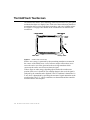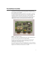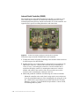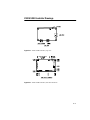
1
Elo IntelliTouch®/SecureTouch
Touchscreen Guide
Revision B
P/N 008212M
Elo TouchSystems, Inc.
1-800-ELOTOUCH
www.elotouch.com
Copyright © 1989, 1992, 1995, 1996, 2001 Elo TouchSystems Inc.
All Rights Reserved.
No part of this publication may be reproduced, transmitted, transcribed, stored in a retrieval system,
or translated into any language or computer language, in any form or by any means, including, but not
limited to, electronic, magnetic, optical, chemical, manual, or otherwise without prior written permission of Elo TouchSystems.
Disclaimer
The information in this document is subject to change without notice. Elo TouchSystems makes no
representations or warranties with respect to the contents hereof, and specifically disclaims any
implied warranties of merchantability or fitness for a particular purpose. Elo TouchSystems reserves
the right to revise this publication and to make changes from time to time in the content hereof without obligation of Elo TouchSystems to notify any person of such revisions or changes.
Trademark Acknowledgments
iTouch, IntelliTouch, SecureTouch, AccuTouch, Entuitive, MonitorMouse, ELODEV, and SmartSet
are trademarks of Elo TouchSystems, Inc.
Other product names mentioned herein may be trademarks or registered trademarks of their respective companies. Elo TouchSystems claims no interest in trademarks other than its own.
i
ii
INTELLITOUCH 10-YEAR WARRANTY
CHAPTER0
Except as otherwise stated herein or in an order acknowledgment delivered to
Buyer, Seller warrants to Buyer that the Product shall be free of defects in
materials and workmanship. The warranty for IntelliTouch touchscreens is 10
years and for IntelliTouch controllers 5 years.
Seller makes no warranty regarding the model life of components. Seller’s
suppliers may at any time and from time to time make changes in the
components delivered as Products or components.
Buyer shall notify Seller in writing promptly (and in no case later than thirty
(30) days after discovery) of the failure of any Product to conform to the
warranty set forth above; shall describe in commercially reasonable detail in
such notice the symptoms associated with such failure; and shall provide to
Seller the opportunity to inspect such Products as installed, if possible. The
notice must be received by Seller during the Warranty Period for such product,
unless otherwise directed in writing by the Seller. Within thirty (30) days after
submitting such notice, Buyer shall package the allegedly defective Product in
its original shipping carton(s) or a functional equivalent and shall ship to Seller
at Buyer’s expense and risk.
Within a reasonable time after receipt of the allegedly defective Product and
verification by Seller that the Product fails to meet the warranty set forth above,
Seller shall correct such failure by, at Seller’s options, either (i) modifying or
repairing the Product or (ii) replacing the Product. Such modification, repair, or
replacement and the return shipment of the Product with minimum insurance to
Buyer shall be at Seller’s expense. Buyer shall bear the risk of loss or damage in
transit, and may insure the Product. Buyer shall reimburse Seller for
transportation cost incurred for Product returned but not found by Seller to be
defective. Modification or repair, of Products may, at Seller’s option, take place
either at Seller’s facilities or at Buyer’s premises. If Seller is unable to modify,
repair, or replace a Product to conform to the warranty set forth above, then
Seller shall, at Seller’s option, either refund to Buyer or credit to Buyer’s
account the purchase price of the Product less depreciation calculated on a
straight-line basis over Seller’s stated Warranty Period.
iii
THESE REMEDIES SHALL BE THE BUYER’S EXCLUSIVE REMEDIES
FOR BREACH OF WARRANTY. EXCEPT FOR THE EXPRESS
WARRANTY SET FORTH ABOVE, SELLER GRANTS NO OTHER
WARRANTIES, EXPRESS OR IMPLIED BY STATUTE OR OTHERWISE,
REGARDING THE PRODUCTS, THEIR FITNESS FOR ANY PURPOSE,
THEIR QUALITY, THEIR MERCHANTABILITY, THEIR
NONINFRINGEMENT, OR OTHERWISE. NO EMPLOYEE OF SELLER
OR ANY OTHER PARTY IS AUTHORIZED TO MAKE ANY WARRANTY
FOR THE GOODS OTHER THAN THE WARRANTY SET FORTH
HEREIN. SELLER’S LIABILITY UNDER THE WARRANTY SHALL BE
LIMITED TO A REFUND OF THE PURCHASE PRICE OF THE PRODUCT.
IN NO EVENT SHALL SELLER BE LIABLE FOR THE COST OF
PROCUREMENT OR INSTALLATION OF SUBSTITUTE GOODS BY
BUYER OR FOR ANY SPECIAL, CONSEQUENTIAL, INDIRECT, OR
INCIDENTAL DAMAGES.
Buyer assumes the risk and agrees to indemnify Seller against and hold Seller
harmless from all liability relating to (i) assessing the suitability for Buyer’s
intended use of the Products and of any system design or drawing and (ii)
determining the compliance of Buyer’s use of the Products with applicable
laws, regulations, codes, and standards. Buyer retains and accepts full
responsibility for all warranty and other claims relating to or arising from
Buyer’s products, which include or incorporate Products or components
manufactured or supplied by Seller. Buyer is solely responsible for any and all
representations and warranties regarding the Products made or authorized by
Buyer. Buyer will indemnify Seller and hold Seller harmless from any liability,
claims, loss, cost, or expenses (including reasonable attorney’s fees) attributable
to Buyer’s products or representations or warranties concerning same.
iv
Table of Contents
IntelliTouch 10-Year Warranty. . . . . . . . . iii
Safety Information . . . . . . . . . . . . . . . . . . .
Summary of Installation Steps. . . . . . . . . .
Unpacking the Touchscreen . . . . . . . . . . .
Testing the Monitor . . . . . . . . . . . . . . . .
Disassembling the LCD Monitor . . . . . . . .
Definition of Terms . . . . . . . . . . . . . . . .
Tools and Equipment . . . . . . . . . . . . . .
Required Parts for Serial Connection . .
Required Parts for USB Connection . . .
Optional Parts for Serial Connection. . .
Optional Parts for USB Connection . . .
Notes on Disassembling the Monitor . . . . .
Removing the Rear Case . . . . . . . . . . . . .
Removing the LCD . . . . . . . . . . . . . . . . . .
Determining Touchscreen Fit . . . . . . . . . . .
Mounting the Touchscreen. . . . . . . . . . . . .
Sealing. . . . . . . . . . . . . . . . . . . . . . . . . . . .
Spacing the LCD from the Bezel . . . . . . . .
Installing the Controller . . . . . . . . . . . . . . .
Internal Serial Controller (2500S) . . . . .
Internal USB Controller (2500U). . . . . .
Power. . . . . . . . . . . . . . . . . . . . . . . . . . . . .
Parasitic Tap of 5Vdc . . . . . . . . . . . . . .
Parasitic Tap of 7-30Vdc (DC to DC
converter) . . . . . . . . . . . . . . . . . . . . . . .
Modifying the Case for Serial Output. . . . .
Modifying the Case for USB Output. . . . . .
Re-assembling the Display . . . . . . . . . . . .
Chapter 1
IntelliTouch Technology . . . . . . . . . . . . 1-1
Introduction . . . . . . . . . . . . . . . . . . . . . . . . . . . . 1-1
The IntelliTouch Touchscreen . . . . . . . . . . . . . . 1-2
The IntelliTouch Controller. . . . . . . . . . . . . . . . . 1-3
Driver Software . . . . . . . . . . . . . . . . . . . . . . . . . 1-4
Agency Approvals . . . . . . . . . . . . . . . . . . . . . . . 1-4
Chapter 2
Component Installation. . . . . . . . . . . . . 2-5
Safety Information . . . . . . . . . . . . . . . . . . . . . . . 2-5
Work Area. . . . . . . . . . . . . . . . . . . . . . . . . . . 2-5
Protective Clothing . . . . . . . . . . . . . . . . . . . . 2-6
Getting Started . . . . . . . . . . . . . . . . . . . . . . . . . 2-6
Design Considerations for CRTs and LCDs . . . 2-6
Bezel Design . . . . . . . . . . . . . . . . . . . . . . . . 2-7
CRT Integration . . . . . . . . . . . . . . . . . . . . . . . . . 2-8
Safety Information . . . . . . . . . . . . . . . . . . . . 2-8
Definition of Terms:. . . . . . . . . . . . . . . . . . . . 2-9
Suggested Tools . . . . . . . . . . . . . . . . . . . . . . 2-9
Summary of Installation Steps . . . . . . . . . . 2-10
Incoming Inspection . . . . . . . . . . . . . . . . . . 2-11
Unpacking the Touchscreen . . . . . . . . . 2-11
Testing the Monitor . . . . . . . . . . . . . . . . 2-11
Disassembling the Monitor . . . . . . . . . . . . . 2-11
Remove the Back Case . . . . . . . . . . . . . 2-12
Discharge the CRT . . . . . . . . . . . . . . . . 2-12
Remove the Electronic Chassis. . . . . . . 2-13
Remove the CRT . . . . . . . . . . . . . . . . . . 2-15
Verify Touchscreen Fit . . . . . . . . . . . . . . 2-16
Attaching the Touchscreen . . . . . . . . . . . . . 2-18
Spacing the CRT from the Bezel . . . . . . . . 2-20
Installing the Controller. . . . . . . . . . . . . . . . 2-21
Internal Serial Controller (2500S) . . . . . 2-22
External Serial Controller. . . . . . . . . . . . 2-25
Internal USB Controller (2500U) . . . . . . 2-27
Routing the Touchscreen Cables . . . . . . . . 2-29
Reassembling the Monitor . . . . . . . . . . . . . 2-29
Sealing the Monitor . . . . . . . . . . . . . . . . . . . . . 2-30
Sealing Material Selection . . . . . . . . . . . . . 2-31
System Evaluation . . . . . . . . . . . . . . . . . . . 2-31
LCD Integration . . . . . . . . . . . . . . . . . . . . . . . . 2-32
2-32
2-33
2-33
2-33
2-34
2-34
2-35
2-35
2-35
2-36
2-36
2-36
2-37
2-37
2-38
2-39
2-41
2-41
2-42
2-42
2-43
2-44
2-44
2-45
2-46
2-46
2-47
Appendix A
Troubleshooting Guide. . . . .A-49
The Troubleshooting Process . . . . . . . . . . . . . A-49
Display Problems . . . . . . . . . . . . . . . . . . . . . . A-50
Software Troubleshooting . . . . . . . . . . . . . . . . A-50
Video Alignment Problems . . . . . . . . . . . . A-51
Hardware Troubleshooting . . . . . . . . . . . . . . . A-51
Serial Controller . . . . . . . . . . . . . . . . . . . . . A-52
Using the COMDUMP Utility . . . . . . . . . A-52
2500S Controller Protocol . . . . . . . . . . . . A-53
A-4002 Controller Protocol . . . . . . . . . . . A-53
RS-232 Connections. . . . . . . . . . . . . . .
Power Connections . . . . . . . . . . . . . . . .
Touchscreen and Touchscreen Cables. . . . . .
IC1 Cable . . . . . . . . . . . . . . . . . . . . . . .
EC2 Cable. . . . . . . . . . . . . . . . . . . . . . .
v
A-54
A-55
A-56
A-57
A-57
Diagnostic LED's . . . . . . . . . . . . . . . . . . . . A-58
IntelliTouch Serial Controllers . . . . . . . . A-58
Diagnostic Codes . . . . . . . . . . . . . . . . . . . . A-59
IntelliTouch Serial Controller (2500S) . . A-59
DB9 and DB25 Connector Pin Positions . . A-60
Appendix B
Specifications . . . . . . . . . . . .B-61
IntelliTouch Touchscreens . . . . . . . . . . . . . . . . B-62
IntelliTouch 2500U USB Controller . . . . . . . . . B-64
LED Diagnostic Characteristics . . . . . . . B-68
Agency Approvals. . . . . . . . . . . . . . . . . . . . B-68
2500U USB Controller Drawings . . . . . . . . B-69
IntelliTouch 2500S Serial Controller . . . . . . . . B-71
Jumper Settings. . . . . . . . . . . . . . . . . . . B-75
LED Diagnostic Characteristics . . . . . . . B-75
Agency Approvals. . . . . . . . . . . . . . . . . . . . B-76
Drawings. . . . . . . . . . . . . . . . . . . . . . . . . . . B-77
Appendix C
Elo Part Numbers . . . . . . . . . . .79
Glossary . . . . . . . . . . . . . . . . . . . . . . . . . . 83
Index . . . . . . . . . . . . . . . . . . . . . .89
vi
List of Figures
IntelliTouch Touchscreen . . . . . . . . . . . . 1-2
IntelliTouch controller . . . . . . . . . . . . . . 1-3
Bezel design . . . . . . . . . . . . . . . . . . 2-7
Bezel edge . . . . . . . . . . . . . . . . . . 2-8
Typical IntelliTouch Touchscreen Installation . 2-10
Proper placement of adhesive tape to the
touchscreen. . . . . . . . . . . . . . . . 2-19
Touchscreen Cabling System for Internal Serial
Controller . . . . . . . . . . . . . . . . 2-22
Internal USB Controller (2500U) . . . . . . . 2-27
Proper and Improper Sealing . . . . . . . . . 2-30
Proper and Improper Bezel Mounting . . . . 2-31
Attaching double-sided adhesive tape to the
touchscreen . . . . . . . . . . . . . . . 2-40
2500S Internal Serial Controller . . . . . . . 2-42
2500U USB controller . . . . . . . . . . . . . 2-43
DC to DC converter . . . . . . . . . . . . . . 2-45
Horizontal escutcheon plate . . . . . . . . . 2-47
Pin positions for the serial port connector . . A-54
Transducer and Wedge Assembly . . . . . . A-56
Pinouts for the IC1 Cable . . . . . . . . . . . A-57
DB9 and DB25 Connector Pin Positions . . . A-60
P2, USB board-mounted header and cablemounted plug. . . . . . . . . . . . . . . B-66
Pin diagram for touchscreen connector, P3, as
viewed from connector mating surfaces. B-66
Power connector board-mounted header and cable
mounted-plug. . . . . . . . . . . . . . . B-66
2500U USB Controller, top view . . . . . . . B-69
2500U USB Controller, thru-hole locations . . B-69
2500U USB Controller, bottom-view . . . . . B-70
2500U USB Controller, side view . . . . . . . B-70
Pin diagram for serial connector, P2, as viewed
from connector mating surfaces. . . . . B-72
Pin diagram for touchscreen connector, P3, as
viewed from connector mating surfaces. B-74
Pin diagram for power connector, P4, as viewed
from connector mating surfaces . . . . . B-74
2500S Serial Controller, top view . . . . . . . B-77
2500S Serial Controller, bottom view . . . . . B-77
2500S Serial Controller . . . . . . . . . . . . B-78
2500S Serial Controller, side view . . . . . . B-78
vii
viii
List of Tables
Serial port controller signals . . . . . . . . . A-54
Pinouts for IC1 Cable and header . . . . . . A-57
The IntelliTouch Serial Controller (2500S) bit
position relating to each byte. . . . . . . A-59
USB connector pin numbers and signal
names . . . . . . . . . . . . . . . . . . B-66
IntelliTouch touchscreen connector pin numbers
and signal descriptions . . . . . . . . . B-67
Power connector, P4 pins and signal
descriptions . . . . . . . . . . . . . . . B-67
Serial Connector, P2, signal names and
functions . . . . . . . . . . . . . . . . B-73
Serial signal electrical characteristics . . . . B-73
Touchscreen connector, P3, pins and signal
names . . . . . . . . . . . . . . . . . . B-74
Power connector, P4, pins and signal names . B-75
Jumper Locations and function if installed . . B-75
ix
x
CHAPTER
1
INTELLITOUCH TECHNOLOGY
CHAPTER1
Introduction
The IntelliTouch system has three main components: a clear solid glass screen
formed to match the shape of a display, a sophisticated electronic controller, and
a software driver. The IntelliTouch touchscreen is based on patented surface
wave technology. Surface waves are mechanical waves that propagate in the
surface of materials such as glass. The touchscreen may be a flat glass panel or a
segment of a sphere or cylindrical glass. This panel is installed over the face of
the display. Because there are no layers or coatings on the glass as with other
technologies, the IntelliTouch touchscreen is extremely durable and allows a
clear, sharp image.
IntelliTouch touchscreen features include:
• Excellent image clarity with high light transmission
• Extremely fast and sensitive, with the highest resolution of any touchscreen
• Excellent durability, resistant to deep scratches and abrasion
• Activated by a finger, gloved-hand or soft stylus
• Inherently stable, drift-free operation
• Dirt and splash sealing capability
• Z-axis response
• Standard sizes for flat, spherical, and cylindrical displays
• Choice of surface treatment (clear, anti-glare or privacy filter)
• Custom sizes available for OEM quantities
• 10-year touchscreen warranty
1-1
The IntelliTouch Touchscreen
The IntelliTouch surface wave technology touchscreen consists of a glass panel
molded to the shape of a display's face. Each axis of the touchscreen panel has a
transmitting and receiving piezoelectric transducer, and sets of reflector stripes.
See Figure 2.3 on page 10 for details on the construction of an IntelliTouch
touchscreen.
Figure 1.1
IntelliTouch Touchscreen
Surface wave energy is generated by the transmitting transducers mounted in
the corners of the touchscreen. A set of reflector stripes reflects these waves
across the active area of the glass and to the receiving transducer which
reconverts the surface waves into an electrical signal.
When a finger or other energy-absorbing object touches the touchscreen a
portion of the wave is absorbed. The resulting change in the received signal is
analyzed by the controller and a digitized X and Y coordinate is determined. A
Z-axis level is determined by measuring the amount of signal attenuation at the
touch location. The X, Y, and Z coordinates are determined and the controller
transmits them to the computer.
1-2
IntelliTouch/SecureTouch Guide
The IntelliTouch Controller
The IntelliTouch controller provides the drive signal for the touchscreen,
converts the received analog signals into digital touch coordinates, and sends
these coordinates to the computer.
The controller detects touches by comparing received signals to a reference
waveform acquired when the touchscreen is in an untouched condition. The
IntelliTouch controller detects dirt, dust particles, scratches and other
contaminants on the screen and “learns around” them. It incorporates those
signals into the reference waveform to ignore the contaminants. If the
contamination is removed, the controller relearns the reference signal.
Figure 1.2
IntelliTouch controller
Because of the stability of the IntelliTouch system, video realignment is not
necessary unless the position of the video image changes.
Resolution of the IntelliTouch system is defined by the controller and is
typically 4096 x 4096, with the controller transmitting at a rate of 48
coordinates per second during a touch.
The controller performs advanced internal diagnostics as well as touchscreen
diagnostics. The diagnostic results are obtainable through software as well as a
diagnostic LED. USB and serial controllers are available.
1-3
Driver Software
Elo driver software provides a consistent software interface among all Elo
touchscreens and controllers.
The driver software scales the absolute coordinates received from the
touchscreen controller into translated screen coordinates, using the calibration
points obtained with the video alignment program included with the driver
software. The driver also performs other operations as directed by the
application.
Elo provides driver programs for the DOS, Windows 3.1, Windows CE,
Windows 95/98, Windows NT, Windows 2000, OS/2, and Macintosh operating
systems. Additional drivers are also available. Additional operating systems are
supported through outside sources. Refer to the Elo web site,
www.elotouch.com, for details.
If you cannot use an available driver, Elo can supply all the touchscreen related
information you will need to write your own driver for any type of system,
including UNIX workstations, real-time systems, and embedded systems. For
the 2500S controller, the SmartSet™ Touchscreen Controller Family Technical
Reference Manual which is available on the Elo website, provide information
on this process. Machine-independent source code is included on a companion
disk and Web site, www.elotouch.com.
Agency Approvals
Elo IntelliTouch touchscreens and controllers are “CNR/USR” UL Recognized
Components for USA and Canada, Category NWGQ2, Information Technology
Equipment Including Business Equipment.
Elo IntelliTouch touchscreens and controllers are TUV Bauart certified as
components.
Elo IntelliTouch touchscreens and controllers have been tested for compliance
with FCC Part 15 Class B limits.1
1. Depending on the application, it may be necessary to pay special attention to system grounding and
shielding, and it may be necessary to apply ferrite suppressor beads.
1-4
IntelliTouch/SecureTouch Guide
CHAPTER
2
COMPONENT INSTALLATION
CHAPTER2
This chapter outlines the procedures for installing touchscreen components that
will convert your monitor into a touchmonitor. Details are given on mounting
the touchscreen, controller, and connecting cables.
Safety Information
WARNING
The touchscreen installation procedure outlined in this chapter may require exposure to
high-voltage components and handling of the CRT. This procedure can be dangerous
and an accident is potentially lethal. Therefore, the procedure should only be performed
by a qualified person. Read this entire chapter before attempting a touchscreen
installation.
Follow the procedure carefully, work with the power off and the unit unplugged, observe
all warnings, and wear protective clothing. Elo is not liable for damage or injury resulting
from the users actions.
Consider purchasing a touch monitor from Elo if you do not have previous
experience working with touchscreens and disassembling displays. Elo also
offers touchscreen installation services in quantity for a variety of displays or
can recommend third-party intergators in your area.
Work Area
Before proceeding with the installation, prepare a padded work surface. A
plastic waste basket is recommended for supporting the CRT during part of the
installation.
2-5
Protective Clothing
Wear safety glasses, gloves, a rubber apron, and heavy protective clothing for
any portion of this procedure that involves handling or working near the CRT.
Getting Started
There are two types of display technologies, CRT displays and LCD displays.
IntelliTouch touchscreens are available for most displays, however each display
may pose unique installation issues. If, after reading these instructions, you need
further assistance please contact Elo Application Engineering for more
information.
These instructions assume you have purchased an Elo Touchscreen Kit and
Touchscreen Installation Kit. Only a minimum of equipment and materials is
required beyond what is provided in the kits. Before proceeding with the
component integration design considerations, please review the section on page
6, Design Considerations for CRTs and LCDs, in order to optimize your
touchmonitor performance.
Design Considerations for CRTs and LCDs
Before designing an LCD or a CRT touchmonitor you should consider the
following criteria (all detailed later in the chapter.):
• Ensure the touchscreen active area and overall glass dimensions are
compatible with the display viewing area. For CRT displays, additionally
check to make sure the radius of curvature (ROC) of the display matches the
radius of curvature of the touchscreen.
• Ensure that adequate power is available for the controller.
• Ensure the bezel does not contact the transducers located on the edge of the
touchscreen.
• Ensure the bezel lands in the sealing area of the touchscreen. See Figure 2.1
on page 7.
• Ensure there is a suitable location to mount the IntelliTouch controller.
• A seal should be used between the display bezel and the touchscreen. Ensure
that the display and its mounting can withstand the force from the
compressed seal. See page 30.
• Ensure the CRT tube can be moved back so there is space for the
touchscreen.
2-6
IntelliTouch/SecureTouch Guide
• To prevent touchscreen breakage, there should be a compliant gasket
between the back of the touchscreen and the front of the display to allow for
variation in the surfaces when assembling. A gap is also required between the
touchscreen and the face of an LCD display to prevent damage to the display.
• Unlike CRT's, plasma, EL, and backlit LCD displays may be a significant
source of heat. The situation may be more significant if the unit is sealed.
Any installation must avoid heat rise that exceeds the touchscreen
specification.
Bezel Design
The following graphic displays some bezel ideas in order to help you mount the
bezel to the touchscreen.
Hard
Lip
Before
Compression
Transducer
Wedge
Bezel
With thin bezel,
add a 2-3mm
hard lip to
protect
transducer
wedge.
Figure 2.1
With thick
bezel, mill
out hole for
transducer
wedge.
Even on a beveled touchscreen,
the transducer sticks up 1mm
above the glass. Add a spacer
to ensure clearance. Seal
thickness will not suffice.
After
Compression
Another idea:
Add a hard lip
behind the seal
to control
compression.
Bezel design
2-7
Bevel edge for nice appearance
Round corners for nice appearance and easy cleaning
On bezel and cabinet, choose paint finish and/or
surface texture so fingerprints do not show
Figure 2.2
Bezel edge
It may be necessary to cut ribs and struts inside the bezel. Cutting these ribs and
struts does not usually cause difficulties, although the stiffness of the bezel may
be reduced slightly. Try not to cut into the posts for the CRT attachment screws.
Bezel and tube combinations that require this cut are rare.
Generally, a total clearance between the edge of the touchscreen and any ribs or
struts of at least 0.25-inch (6 mm) in both axes is necessary. This prevents the
interference fit problem and allows for variation in touchscreen mounting
position.
CRT Integration
Safety Information
Before proceeding with the installation, prepare a padded work surface. A
plastic waste basket is recommended for supporting the CRT during part of the
installation. Wear safety glasses, gloves, a rubber apron, and heavy protective
clothing for any portion of this procedure that involves handling or working
near the CRT.
Note:
2-8
This document describes the basic tasks common to the majority of CRT monitor
integrations. These instructions assume an audience of trained integration personnel.
IntelliTouch/SecureTouch Guide
Definition of Terms:
MONITOR: The term "monitor" refers only to the monitor, television, or other
display that is to be integrated.
BEZEL: The term “bezel” refers to a specific part of the molded plastic cabinet
of the monitor. The bezel is the part that covers the front of the CRT and
separates it from the rear case.
CASE: The term "case" refers to a specific part of the molded plastic cabinet of
the monitor. The case is the part that separates from the front bezel. The case
normally covers the top, sides, back and bottom of the monitor assembly.
LCD: Liquid Crystal Display. Also referred to as the Panel.
CONTROLLER: The electronic device that converts touch data into USB
information. For purposes of this document the controller referred to is the
2500U, which is the Elo internal IntelliTouch USB controller 2500U. Part
number 714259-000.
Suggested Tools
Along with a copy of the monitor manufacturer’s manual, the following list of
tools may be needed to install the touchscreen. Some of the tools are optional,
but useful.
• Long (at least 9 inches, 230 mm) flat blade screwdriver with insulated handle
• Clip lead or heavy-gauge wire
• #2 Phillips screwdriver
• Scissors
• X-Acto knife (No. 11 blade) or hand milling tool
• DB9 hole punch (not needed for 2500U)
• Cable ties
• Household glass cleaner
• Paper towels
• Small containers or plastic bags to hold loose parts
The Elo Touchscreen Installation Kit is also recommended, and includes
commonly used materials needed for touchscreen installation. This kit is useful
for identifying preferred materials for your own procurement and may also be
cost-effective and convenient when purchased for a limited number of
installations. (See “Elo Part Numbers” on page 79.)
2-9
Summary of Installation Steps
The CRT installation process consists of the following steps:
1 Incoming inspection
2 Disassembling the monitor
3 Attaching the touchscreen to the CRT
4 Installing the controller
5 Routing the touchscreen cables
6 Reassembling the monitor
7 Sealing the monitor
Specific compatibility may not be confirmed until well into the installation.1
IntelliTouch touchscreens can be installed on most types of CRT displays.
Figure 2.3 shows a typical installation.
Figure 2.3
Typical IntelliTouch Touchscreen Installation
Most displays require complete disassembly, including removal of the CRT, to
install a touchscreen. Disassembling the display can be a dangerous procedure if
done improperly. Any damage to the display or the touchscreen as a result of
improper installation is the installer’s responsibility. Without prior approval of
the display manufacturer, you will probably void the display’s warranty by
disassembling it. Also, it will be necessary to recertify the display and
touchscreen system for regulatory agencies such as FCC, CE and UL/CSA if
those certifications were originally present and need to be maintained for your
intended application.
1. To complete the first integration may take several hours.
2-10
IntelliTouch/SecureTouch Guide
Incoming Inspection
Unpacking the Touchscreen
Handle the touchscreen with care. Note the transducers in the corners are
especially fragile. Note the location of the transducers and wiring. If any of
these are accidentally broken during handling or installation, or if a wire is
pulled loose, the touchscreen will not operate. Avoid excessive handling and
stress on the touchscreen cable. Wear gloves to avoid getting fingerprints on the
touchscreen. The touchscreens are pre-cleaned by Elo.
Testing the Monitor
The CRT display must be in good working order before beginning the
installation of the touchscreen. Inspect the monitor for cosmetic flaws or
damage. With a new display, it is suggested that you test the display by running
it overnight. Check for acceptable color, linearity, brightness, contrast,
distortion, and other QC tests.
Disassembling the Monitor
Disassemble the monitor on a large, well-lit work surface. Leave space to set
aside major display components. Group screws and other hardware in small
containers or in specific areas on the work surface as you remove them, in
relation to the part of the display where you are working.
Most display manufacturers connect the major components with detachable
cables that have labeled and keyed connectors; these cables are of lengths that
will usually connect to only one place. Also, screws are identifiable by type and
size, and usually will not fit in the wrong place. The most difficult problem with
missing or wrong hardware or connections will be with ground cables that
attach to obscure ground points on the metal chassis. When in doubt, make
notes of the connection points.
2-11
Remove the Back Case
Figure 2.3 on page 10 shows the typical construction of a 15-inch display.
Disassembly usually starts with removal of the back case. For assistance with
disassembly, consult your particular manufacturer's service manual. Carefully
lay the monitor on its face on the padded work surface and remove the screws
that attach the back case to the bezel or frame.
While removing the back case, note the clearance between the inside rear
surface of the case and a small circuit board plugged into a socket on the end of
the CRT. If there is not enough clearance to move the CRT and this circuit
board about.25 inch (6 mm) toward the rear of the case, you may be unable to
successfully install a touchscreen on the display and completely reinstall the
back case. Contact Elo Application Engineering, (1-800-557-1458 x6) for
possible alternatives.
After the back case is removed, the CRT is substantially exposed. Use extreme
care when working around the CRT.
WARNING
Impact or force against the neck of the CRT, or the pins at the end where the small circuit
board is attached, could crack the tube, resulting in loss of vacuum or implosion of the
tube. Either result destroys the CRT. Implosion (collapse of the glass inward, caused by
the high vacuum inside the tube), followed by the rebound of many glass pieces outward,
is potentially lethal to anyone in the immediate area. Handle the CRT carefully, keep tools
away from the CRT, and wear protective clothing including eye protection and gloves.
Discharge the CRT
WARNING
Dangerous voltages may be present on the CRT anode. The anode may retain a very
dangerous voltage even after the display has been off for days. While most CRT monitors
now incorporate bleeder circuits to discharge the CRT, one must not assume that the
CRT is properly discharged. Accidental contact with the anode lead or anode button (the
small hole in the CRT glass where the anode lead is attached) prior to discharge may
result in a potentially lethal shock. Follow the procedure below carefully.
The anode lead of the display feeds high voltage from the flyback transformer to
the anode button on the CRT. The anode lead is usually red in color, and the
actual connection to the anode button is usually covered by a large rubber
suction cup-like boot. In most displays, the button is located on the tapered face,
or bell, of the CRT glass near the top of the display. See Figure 2.3 on page 10.
2-12
IntelliTouch/SecureTouch Guide
It may be necessary to remove some sheet metal to gain access to the anode
lead—be very careful to do this without making contact to the anode lead itself.
Carefully discharge the CRT using the following procedure:
1 Connect a clip lead or a heavy-gauge wire to the mounting ears or the spring-
tensioned ground strap.
2 Connect the other end of the clip lead or wire to the stem of a flat blade
screwdriver that has an insulated handle.
3 Hold the screwdriver by the insulated handle only. Insert the blade of the
screwdriver under the rubber boot and make contact with the anode lead at
the button. A distinct “snap” may or may not be heard as it discharges,
depending on the amount of charge present on the anode.
4 Disconnect the anode lead from the button by unhooking the spring wire
clips. Note the location of the anode for proper CRT orientation during
reassembly.
WARNING
The CRT will regain a charge over time, even after it has been discharged. To avoid a
dangerous electric shock, always discharge the CRT just before handling it, and treat it
with respect thereafter.
Remove the Electronic Chassis
Continue disassembling the display until the face of the CRT is completely
exposed. The degree of disassembly required will vary from display to display.
Normally the next step will be to remove the electronics chassis from the
display. This requires removal of a small circuit board that is usually plugged
into the socket on the end of the CRT. The circuit board is often glued to the
CRT socket with a soft adhesive which must be cut away to remove the board.
Several cables must also be unplugged from the electronics. Typically these
cables are:
• Four wires from the yoke of the CRT, typically in a single four-pin
connector. The yoke is the copper wire and magnet assembly at the base of
the neck of the CRT. MPR II-compliant monitors may have additional cables
and connectors on the yoke.
• A two-wire cable from the degaussing coil. This coil may be attached to the
CRT, or be laying out of sight between the CRT and the bezel. Some
monitors may have two separate coils.
• A one- or two-wire ground cable connected between the CRT circuit board
and a ground strap. This strap is a long, uninsulated, braided wire which is
spring-tensioned to maintain contact with the bell of the CRT.
• Various cables connected to the power switch, pilot light, front panel
controls, etc.
2-13
• Various cables connected to the power switch, pilot light, front panel
controls, etc.
Other cables may have to be unplugged from the electronic chassis. The need
for this may not be apparent until the chassis is removed, as instructed below.
Another preliminary step in determining touchscreen/display compatibility
should be performed at this point. Before removing the electronics chassis, note
the clearance between the chassis components and the bell of the CRT. Since
the standard technique for mounting the touchscreen involves moving the CRT
back in the display chassis, there must be enough clearance between
components on the chassis and the CRT after allowing for about 0.25-inch
(6 mm) movement of the CRT towards the rear of the chassis. Failure to allow
for this clearance requirement may result in mechanical damage later
(especially in shipping). It may also cause electrical damage from shorts
between “live” components on the chassis, such as heat sinks or uninsulated
component leads, and the bell of the CRT which is usually painted with a
conductive coating that is grounded to the chassis through the braided wire
ground strap. Repositioning or substituting low profile components may be an
option. Contact Elo Technical Support, (1-800-557-1458 x6), for assistance.
After disconnecting any necessary cables remove the screws that attach the
electronics chassis to the bezel. Note the bezel is essentially where all parts of
the mechanical assembly are attached, unless you have a rare unit that has an
internal frame. As you pull the chassis away from the bezel, make sure that
cables and circuit boards do not hit the neck of the CRT and that nothing
becomes caught on the adjustment rings or other components on the neck of the
CRT. Also watch for other cables that need to be disconnected. After removal,
set the electronics chassis aside.
2-14
IntelliTouch/SecureTouch Guide
Remove the CRT
Removal of the CRT is next. Prepare a soft surface to set the CRT on. Remove
the screws attaching the CRT to the bezel, and then remove the CRT. Do not lift
or carry the CRT by the neck or yoke assembly. Avoid contact with the anode
button, which may still have some residual charge on it, (you may wish to
discharge it again at this point). Set the CRT on the prepared surface.
Several other preliminary compatibility requirements should now be assessed:
• Position the CRT so the face is accessible, providing a soft cushion for the
neck and the yoke if they must rest on the work surface. Alternatively, set the
CRT face-up in an office-type plastic waste basket, making sure that the tube
is not resting on the neck (The small thin part of the CRT is the neck). Place
the touchscreen on the face of the tube, and check to see that the face of the
CRT and touchscreen are about the same size, and that the radius of curvature
(ROC) of each surface matches well. If both of these conditions are not met,
you may not have the proper touchscreen for the display. Most color displays
have standard size CRT's with standard ROC's, and Elo has touchscreens for
most of them.
• Next, determine if the touchscreen will fit in the bezel without modifications
to the bezel. Modifications, if necessary, should be done without
compromising the mechanical integrity of the display.
• Lay the touchscreen face-down in the bezel, being careful not to damage the
transducers. Leave the degaussing coil in place, if present. The degaussing
coil is a hoop, often located between the CRT and bezel, approximately
0.25-inch (6 mm) thick, with a two-wire cable and connector. The coil was
probably unplugged from the power supply earlier.
If the touchscreen will not fit flush against the lip of the bezel, do not force it.
An interference fit between the edge of an IntelliTouch touchscreen and some
of the plastic ribs found in display bezels can pinch and break the small wires
which carry the signals along the edges of the touchscreen or even result in
fracture of the glass after reassembly.
It may be necessary to cut these ribs and struts inside the bezel. Cutting these
ribs and struts does not usually cause difficulties although the stiffness of the
bezel may be reduced slightly. Try not to cut into the posts for the CRT
attachment screws. Bezel and tube combinations that require this cut are rare.
Generally, a total clearance between the edge of the touchscreen and any ribs
or struts of at least 0.25-inch (6 mm) in both axes is necessary. This prevents
the interference fit problem discussed above and allows for variation in
touchscreen mounting position.
2-15
The potential interference between the degaussing coil and the touchscreen
must also be evaluated. The coil will usually fit between the touchscreen and
the inside surface of the bezel, as there is typically a natural cavity for it. If
there is not enough space for the coil, you may have to provide additional
setback for the CRT. It may also be possible to relocate the coil to the bell
side of the CRT. Normally, this does not significantly reduce the coil’s
effectiveness. However, you must determine this by inspecting the display
for color problems after reassembly.
• Check for adequate clearance of the transducers and the cable from the bezel
structure. If the position of the cable causes difficulty, the touchscreen may
be rotated 180° (only if the touchscreen is sealed and using Elo drivers).The
preferred orientation of the IntelliTouch touchscreen is with the cable exiting
from the right side, when viewed from the front of the display. Rotation will
cause an inversion of the output coordinates, which will be compensated for
automatically by Elo driver software, but perhaps not by other drivers. (Flat
touchscreens should have the reflector stripes on the side facing the user.)
Verify Touchscreen Fit
1 Check to ensure touchscreen dimensions match CRT display. Place the
touchscreen on the face of the tube to see that the face of the CRT and
touchscreen are about the same size, and that the radius of curvature (ROC)
of each surface matches well. If both of these conditions are not met, you
may not have the proper touchscreen for the display. Most color displays
have standard size CRT's with standard ROC's, and Elo has touchscreens for
most of them.
2 Determine if the touchscreen will fit in the bezel without modifications to the
bezel. The bezel should not touch the transducers and should land in the
sealing area, not on the reflector strips.2 Modifications, if necessary, should
be done without compromising the mechanical integrity of the display. Also
see Bezel Design section for recommendations.
Note:
If the touchscreen will not fit flush against the lip of the bezel, do not force it. An
interference fit between the edge of an IntelliTouch touchscreen and some of the plastic
ribs found in display bezels can pinch and break the small wires which carry the signals
along the edges of the touchscreen or even result in fracture of the glass after
reassembly.
2. Clearance around the transducers should be 1-2 mm clearance above transducers (to prevent
dampening vibration, electrical short or breakage), and 3-5 mm around transducers. Allow for
manufacturing variances of touch screen and integration. If the position of the cable causes difficulty,
the touchscreen may be rotated 180°. The preferred orientation of the IntelliTouch touchscreen is with
the cable exiting from the right side, when viewed from the front of the display. Rotation will cause an
inversion of the output coordinates, which will be compensated for automatically by Elo driver
software, but perhaps not by other drivers. (Flat touchscreens should have the reflector stripes on the
side facing the user.)
2-16
IntelliTouch/SecureTouch Guide
3 It may be necessary to cut ribs and struts inside the bezel. Cutting these ribs
and struts does not usually cause difficulties, although the stiffness of the
bezel may be reduced slightly. Try not to cut into the posts for the CRT
attachment screws. Bezel and tube combinations that require this cut are rare.
Generally, a total clearance between the edge of the touchscreen and any ribs
or struts of at least 0.25-inch (6 mm) in both axes is necessary. This prevents
the interference fit problem discussed above, and allows for variation in
touchscreen mounting position.
4 The potential interference between the degaussing coil and the touchscreen
must also be evaluated. The coil will usually fit between the touchscreen and
the inside surface of the bezel, as there is typically a natural cavity for it. If
there is not enough space for the coil, you may have to provide additional
setback for the CRT. It may also be possible to relocate the coil to the bell
side of the CRT. Normally, this does not significantly reduce the coil’s
effectiveness. However, you must determine this by inspecting the display
for color problems after reassembly.
5 Check for adequate clearance of the transducers and the cable from the bezel
structure. If the position of the cable causes difficulty, the touchscreen may
be rotated 180° (only if the touchscreen is sealed and using Elo drivers).
6 The preferred orientation of the IntelliTouch touchscreen is with the cable
exiting from the right side, when viewed from the front of the monitor.
Rotation will cause an inversion of the output coordinates, which will be
compensated for automatically by Elo driver software, but perhaps not by
other drivers. (Flat touchscreens should have the reflector strips on the side
facing the user.)
2-17
Attaching the Touchscreen
Once you have verified all dimensions and checked that the bezel has plenty of
clearance around the transducers and lands inside the sealing area, you are ready
to install the touchscreen.
1 Check room for cable routing:
• Route away from noise sources (flyback transformer, power supply, yoke,
high voltage lead, etc.)
• Cable can be on either side.
• Avoid pinch points.
• Make up excess cable with tie wraps.
2 Ensure the display and touchscreen and are clean before installation.
• Use black background to ensure fingerprints and smudges are not visible.
• Compressed air is best to remove dust.
3 Use double-sided high tack adhesive tape3 on all four sides to attach the
touchscreen to the display.
• 3 mm thick for curved
• 2 mm thick for flats > 15"
• 1 mm thick for flats <= 15"
• Acts as dust seal as well as an adhesive. (Make a flat “T” in corners for
dust seal.)
• Or substitute foam tape on two sides
• Or use metal frame on flats, but still use foam tape for dust seal.
3.Refer to “Elo Part Numbers” on page C-79 to ensure you are using the proper
adhesive
2-18
IntelliTouch/SecureTouch Guide
Use two layers of the double-sided adhesive tape to achieve a total thickness
of 1/16-inch (2 mm). While specific touchscreen and CRT combinations may
allow the use of thinner materials, 1/16-inch (2 mm) is generally necessary to
allow for variations in ROC between the two glass surfaces. Review the fit
between the touchscreen and the CRT before applying the tape. If one pair of
opposite edges has a closer fit than the other, put the adhesive tape on the
edges of the touchscreen with the better fit. See Figure 2.4 on page 19 for
typical placement. You want the sealing tape on the rear of the touchscreen
so it can’t be seen in the viewable area once reassembled. If there is a good fit
on all four edges, you may want to use double-sided adhesive tape on all four
edges. When doing this, move the adhesive tape in slightly on one pair of
edges and add foam sealing tape outside these two edges. The thicker foam
tape will keep the adhesive tape away from the CRT until you are ready to
adhere the touchscreen to the display.
Figure 2.4
Proper placement of adhesive tape to the touchscreen.
In general, the adhesive tape should be set back slightly from the edge of the
active area of the touchscreen. The adhesive tape should be attached to the
glass. When the display is reassembled, the mounting tape should not be
visible. Do not remove the liner from the exposed side of the adhesive tape
yet.
Cut and place the foam sealing tape on the back of the touchscreen to form a
dust seal as shown in Figure on page 31. This seal is particularly important
because the CRT is a good electrostatic precipitator and will attract dust. The
adhesive tape and foam sealing tape should form a complete seal around the
touchscreen. Do not leave any gaps. The sealing tape should not be visible
when the display is reassembled.
Practice aligning the touchscreen on the CRT without removing the adhesive
tape liner. The installation can tolerate some horizontal and vertical shift.
However, rotational skew between the touchscreen and display axes cannot
be easily compensated for in the video alignment, and will also interfere with
proper mounting of the tube in the bezel.
2-19
When you have a good feel for the placement of the touchscreen, clean the
back side of the touchscreen and the face of the CRT again. Avoid all contact
between the cleaning solution and the mounting materials as the cleaner may
cause the mounting materials to eventually release from the glass. Remove
all lint with a brush or compressed air. Remove the liner from the adhesive
tape and align the touchscreen on the display. The thicker foam tape will
keep the adhesive tape away from the CRT until you are ready to adhere the
touchscreen to the display. Now press the touchscreen firmly against the
CRT.
If you must remove the touchscreen from the CRT, cut the adhesive tape
away with a sharp thin blade, such as an X-Acto knife. The touchscreen glass
will probably break if you try to pull it off by a corner or an edge. Shave the
old adhesive tape from the touchscreen and CRT with the knife. Adhesive
residues can be removed with denatured alcohol, which will leave streaks and
fingerprint smears. Use glass cleaner for the final cleaning prior to
reapplication of new tape.
4 Place touchscreen on CRT straight and centered.
5 Peel off 3 cm of tape backer in two opposite corners. Fold to make tabs.
6 Pull back on tab to remove tape backer from under touchscreen while
pressing on touchscreen.
7 Ensure there is nothing, such as tape, touching the reflector strips or
transducers.
Spacing the CRT from the Bezel
The last part of the touchscreen mounting procedure is to determine the
appropriate spacing of the CRT from the bezel, (with the touchscreen attached),
and to reinstall the CRT with the required spacers in place (refer to Figure 2.8
on page 31). Do not clamp the touchscreen between the bezel and the CRT
without proper spacers as breakage will almost certainly occur. The nominal
thickness of the touchscreen and the two layers of adhesive tape is 3/16-inch
(5 mm). If the touchscreen is to be in contact with the bezel, 3/16-inch (5 mm)
nominal spacers would be required.
Because the original CRT face-to-bezel mount is often an interference fit, with
the bezel shape altered slightly to draw it up tightly against the CRT, you should
start with a 1/16-inch (2 mm) thicker spacer than the nominal dimension above.
Two thicknesses of spacers, plus additional washers to use as shims, are
available in the Touchscreen Installation Kit. (See “Elo Part Numbers” on
page C-79 for Touchscreen Installation Kit).
2-20
IntelliTouch/SecureTouch Guide
During the spacer selection process, you may have to install the CRT with the
touchscreen attached in the bezel several times. To prevent the CRT from
dislodging the spacers, temporarily insert plastic tie wraps or toothpicks as
guides in the mounting post holes. After selecting the correct spacers, discard
the guides and fix the spacers more securely in place with the adhesive
"doughnuts" provided in the Touchscreen Installation Kit.
When spacers for the desired gap have been selected, install the CRT. Make
sure you have previously reinstalled the degaussing coil. Select a screw that is
long enough to compensate for the spacer thickness (provides at least three full
turns into the mounting post threads) but not so long as to penetrate the surface
of the bezel. Over-tightening the screws may strip or split the mounting posts.
Installing the Controller
Elo offers IntelliTouch USB or serial (RS-232) controllers which are typically
installed internal to the display.
Before installing an IntelliTouch controller, you need to ensure the following
design conditions:
• Ensure there is space for the controller and the cable headers.
• Note that cable routing may contribute to noise and crosstalk. Make sure
the controller is placed away from voltage sources.
• Ensure there is space for an internal DC-to-DC converter or AC power
supply if either is required.
• Verify power source and check specs for adequate power. The 2500
controllers use +5V@60 mA ±5% regulated.
• Ensure sufficient electromagnetic Interference (EMI) suppression. Installing
a touchscreen and controller will affect the EMI characteristics of the display.
Note:
Ensure sufficient heat dissipation. The IntelliTouch serial controller dissipates some heat
(less than 1 watt). A typical power supply, if required, may dissipate several watts more.
This places an additional load on the cooling system of the display. The available
locations to mount a controller and power supply may also affect the cooling system of
the display. Only applicable if you are not using AC-to-DC power supply.
• Ensure controller can be mounted securely to metal bracket and grounded.
• Ground at least one mounting hole, but for best EMI characteristics,
ground all four mounting holes.
2-21
Internal Serial Controller (2500S)
The mounting holes of the IntelliTouch serial controllers are sized for 0.156inch (4mm) snap-in standoffs. All IntelliTouch touchscreens have a cable
termination that mates directly with the male header (P3) on the controller. See
Appendix B for specific mounting dimensions and connections.
Figure 2.5
Touchscreen Cabling System for Internal Serial Controller
Follow these steps to install an IntelliTouch serial controller:
1 Evaluate the monitor for proper positioning of the controller. Make sure there
is sufficient space for cable headers.
2 Evaluate the back case of the monitor to determine the best position for the
DB9 female connector. A hole for this connector may be furnished in a
variety of ways: a) mounting the connector to a chassis member that is
exposed to the display exterior, b) mounting the connector to a chassis
member with a hole in the exterior of the case to provide access to the
connector, and c) mounting the connector to the case.
3 Mount and ground the controller card following one of the two methods:
• Mount the controller to the metal chassis using metal screws and spacers.
It can be grounded through one of the mounting holes by using one of the
No. 6 sheet metal screws and spacers provided in the kit (See “Elo Part
Numbers” on page C-79 for installation kit part number). On the 2500S,
all mounting holes are plated.
2-22
IntelliTouch/SecureTouch Guide
• If the controller cannot be mounted to a metal chassis, use a ground wire
with a lug attached to connect one of the controller's plated-through
mounting holes to chassis ground.
4 Connect the power cable harness (See “Elo Part Numbers” on page 79 for
part number) to the 2x5 male connector (See “Elo Part Numbers” on page 79
for part number) at P4 on the controller. Connect the other end to a power
source. If a suitable +5 Vdc power source cannot be found inside the display,
use an AC-to-DC power supply. The 2500S controller power requirements
are +5 Vdc nominal. Refer to Appendix B for current requirements.
P4 Pins
Signal
Function
1
2
+Pwr
PwrCom
Supply voltage positive
Supply voltage negative (tied to pin 4)
3
4
N/C Not connected
PwrCom
Supply voltage negative (tied to pin 2)
5
6
LED Remote
7
8
9
N/C
Chassis
-Reset
10
N/C
External LED driver
Key
Frame ground connection
Open collector input: = normal operation; short to
PwrCom = hardware reset.
If you have grounded the controller to the metal chassis as recommended in
Step 3 on page 22, the chassis ground connection through the power
connector, P4 pin 8, does not need to be connected. Likewise, do not connect
the Reset and LED Remote lines unless you have provided the appropriate
circuits.
The microprocessor pin that drives the status LED is connected to pin 5 of
the P4 power supply connector. This signal from the microprocessor may
also be used to drive an external indicator such as another LED.
To operate an external LED, connect the LED cathode to ground and the
anode to pin 5 of the P4 connector. Nominal current through the LED will be
6 mA, so a low-operating current LED should be used. An external resistor is
not required.
2-23
5 Connect the 2x5 female connector, on the serial output cable (See “Elo Part
Numbers” on page 79), to the 2x5 male connector at P2 on the controller.
Mount the DB9 female end of the cable in the position determined in step 2.
The serial cable connector shell must be grounded to satisfy safety agency
approvals, as the grounding protects the user in case a wiring fault develops
in the display. If the DB9 connector shell is not already grounded, attach the
ground wire supplied in the kit to one of the DB9s mounting screws and the
other end to chassis ground.
6 Adhere the metal plate labeled with the legend, “Touchscreen Interface”, to
the outside of the bulkhead-mounted DB9 connector. A similar plate (See
“Elo Part Numbers” on page 79) is also available with vertical labeling.
7 Label the monitor to indicate what IntelliTouch serial controller is installed
inside the display and include its jumper settings, if any.
2-24
IntelliTouch/SecureTouch Guide
External Serial Controller
An external serial controller is the best choice for many integrators for several
reasons:
• No additional cables are required to install the controller. The 30-inch
touchscreen cable is routed through the rear of the display case to a 2x6 male
connector located on the rear of the controller. Once the controller is installed
on the rear of the display, little or none of the touchscreen cable is visible.
• The base of the controller may be permanently attached to the rear of the
display, but is easily removed from the display if necessary.
• The serial cable is permanently connected to the controller and features an
armored, moisture-resistant sleeve where the cable enters the controller
enclosure.
• An external serial controller offers the added flexibility of using a keyboard
tap or wall-mount power supply (See “Elo Part Numbers” on page 79) if
using an internal power source is inconvenient or impractical. This feature
places fewer constraints on the design and location of kiosks and other
applications.
Follow these steps to install the IntelliTouch external serial controller:
1 Determine supply power source to the controller. The controller requires +5
Vdc regulated power (± 0.25 Vdc) with 100 mA typical. Average power
dissipation is 0.7 W.
CAUTION
Before making any attempt to power the controller from any monitor power source, you
should confirm the installation with your monitor supplier. Failure to observe this caution
may destroy the monitor or seriously impair monitor performance.
• Provided you first confirm the installation with your monitor supplier, you
may attach a direct power cable to a +5 Vdc source inside the display or tap
unregulated monitor power in the +9 Vdc to +30 Vdc range using the Elo
DC-to-DC converter (See “Elo Part Numbers” on page 79). Typical
converter power consumption is approximately 1 W. Remember that each
integration situation is unique; you must carefully evaluate available power
rails and consider how drawing additional power from the display will affect
monitor performance.
If you have a suitable +5 Vdc power source, attach the direct power cable
harness (See “Elo Part Numbers” on page 79) to the source, red to + 5 Vdc
and black to common. You must attach the green ground cable to a suitable
chassis ground for noise immunity and safety considerations. Also ensure
that the cable is long enough to reach the back of the monitor and the
controller.
2-25
CAUTION
Observe polarity when connecting the power leads to the power supply. Reversing
polarity may damage the controller.
Possible power supply sources included:
• A direct power cable to a +5 Vdc source inside the display or tap unregulated
monitor power in the +9 Vdc to +30 Vdc range using the Elo DC-to-DC
converter (See “Elo Part Numbers” on page 79). Attach the direct power
cable (See “Elo Part Numbers” on page 79) to the source, red to + 5 Vdc and
black to common. You must attach the green ground cable to a suitable
chassis ground for noise immunity and safety considerations. Observe
polarity when connecting the power leads to the power supply. Reversing
polarity will damage the controller.
• Typical converter power consumption is approximately 1 W. Remember
that each integration situation is unique; you must carefully evaluate
available power rails and consider how drawing additional power from the
display will affect monitor performance.
• Install a power supply which requires a 100-240 Vac input. Connect a power
cable harness to P4 on the controller, a 2x5 header with pins on 0.100-inch
(2.54 mm) centers. Use a ribbon cable with an IDC connector or crimp-towire pin receptacles. An acceptable plug can be selected from Molex series
70450, Amp AMPMODU Mod. IV product line, or Berg mini-latch housing
with Mini-PV pins. Connect a power supply to the harness and then to AC.
• If none of the above options are practical, you must use either an optional
keyboard power tap or wall-mount power supply to furnish +5 Vdc power
to the controller.
CAUTION
Before using a keyboard power tap, be sure sufficient power is available for the
touchscreen controller or damage may occur to the computer.
Before connecting a keyboard power tap to the controller, be sure that power to the CPU
is OFF. Connecting a keyboard power tap to a powered CPU may seriously damage the
CPU or the controller and will blow the keyboard fuse.
1 Decide where to mount the controller on the rear of the display case. After
choosing a location, use masking tape to hold the template in the desired spot
and drill a 1-inch diameter hole for cabling exiting the display and drill two
holes for screws that will be mounted in the display case.
2 Route the touchscreen cable (and power cable if using an internally located
power source) through the 1-inch diameter hole in the display case. Insert the
touchscreen cable into the keyed receptacle in the rear of the controller box.
You will hear a “click” when the cable connector is properly connected to the
controller. Pull any excess cabling back into the display case and attach the
controller to the display case.
3 Wrap excess cabling with tie wraps as required, and proceed to “Routing the
Touchscreen Cables” on page 2-29.
2-26
IntelliTouch/SecureTouch Guide
Internal USB Controller (2500U)
The mounting holes for the 2500U USB controller are sized for 0.156-inch
(4 mm) snap-in standoffs. All current IntelliTouch touchscreens have a cable
that mates directly with the male header (P3) on the controller. The controller
must be powered from inside the monitor.
Figure 2.6
CAUTION
Internal USB Controller (2500U)
Before making any attempt to power the controller from any monitor power source, you
should confirm the installation with your monitor supplier. Failure to observe this caution
may destroy the monitor or seriously impair monitor performance.
Follow these steps to install the IntelliTouch 2500U USB controller:
1 Evaluate the monitor for proper positioning of the controller. Make sure there
is sufficient space for cable headers.
2 Evaluate the back case of the monitor to determine the best position for the
USB connector. There are two possible configurations for installing the USB
controller.
• Configuration 1: mount the controller card so the USB connector is flush
with the back of the monitor.
• Configuration 2: mount the controller inside the controller inside the
monitor and use the Elo USB cable pack (See “Elo Part Numbers” on
page 79) to mount a USB connector.
2-27
3 Mount and ground the controller card. The grounding scheme for the
controller should typically be determined consistent with EMI suppression
requirements. This may be accomplished one of two ways:
• The controller should be mounted to the metal chassis using metal screws
and spacers. It can be grounded through one of the mounting holes by
using one of the No.6 sheet metal screws and spacers provided in the kit.
• If the controller cannot be mounted to a metal chassis, use a ground wire
with a lug attached to connect one of the controller's plated-through
mounting holes to chassis ground.
4 Connect the power cable harness to the 2x5 male connector at P4 on the
controller. Connect the other end to a power source. If a suitable +5 Vdc
power source cannot be found inside the display, use a dedicated power
supply. The 2500U controller power requirements are +5 Vdc nominal. Refer
to Appendix C for current requirements.
5 If you have grounded the controller to the metal chassis as preferred, the
chassis ground connection through the power connector, P4 pin 8, does not
need to be connected.
6 Plug the X007X cable between the card and the bulk head mounting USB
connector.
7 Adhere the metal plate labeled with the legend, “Touchscreen Interface” to
the outside of the bulkhead-mounted USB connector. A similar plate (see
pg. 79 for part number) is also available with vertical labeling.
8 Label the monitor to indicate that an IntelliTouch 2500U USB controller is
installed inside the display.
2-28
IntelliTouch/SecureTouch Guide
Routing the Touchscreen Cables
The internal cables that carry the analog touchscreen signals are subject to
interference from various sources within the display. The routing of these cables
should avoid the following areas, listed in order of importance:
• flyback transformer-CRT (anode lead)
• anode lead-CRT
• inverter section of the power supply-Flat Panels only (most display power
supplies are switching power supplies, and the main DC to AC inversion
section produces most of the noise)
• yoke-CRT
• RGB video drive section of the display
• video input cable
• horizontal and vertical oscillator/drive sections-CRT (large caps)
Once acceptable cable positioning is determined, tie the cable down to avoid
movement during shipment. In addition to careful cable routing, other EMI
suppression techniques may be necessary to satisfy agency approval
requirements. Use ferrite beads or other radio frequency (RF) suppression
elements, additional shielding, and different grounding techniques as needed.
Also, attach all excess cable/service loops as close to the chassis as practical to
reduce noise emissions.
Reassembling the Monitor
With the touchscreen mounted, and the cable routing and exterior interface
determined, the display must be reassembled. Reassembly is generally in
reverse order of disassembly. Beware of potential clearance problems between
the bell of the CRT and the electronics chassis, as shorts in this area can produce
catastrophic failures of the display. Also, if the inside surface of the back case is
painted with a conductive coating, watch for shorts between the CRT circuit
board and the rear of the back case, as these can also produce disastrous results.
When the electronics chassis is reinstalled, the CRT circuit board is usually
carried along with it. It is often advisable to have a second person assist you, to
insure that this circuit board and various other cables do not interfere with the
yoke or neck of the CRT. Safety glasses, gloves, heavy protective clothing, and
caution are strongly advised for all participants.
2-29
Reconnect all cables that were removed during the disassembly procedure.
Watch for single ground connections from the CRT mount to the chassis,
between individual chassis members, etc., which may have lugs and screws to
connect them, or sometimes individual push-on solderless connectors. Failure
to reconnect these important cables may result in improper performance of the
display after reassembly and may render the unit unsafe.
Re-glue the CRT circuit board to the connector with an electronic-grade
(non-corrosive) silicone adhesive (such as GE RTV-162). Discharge the CRT
again (see Discharging the CRT, page 12), and then reconnect the anode lead to
the anode button, making sure the spring hooks catch inside the hole.
If practical, test the monitor and touchscreen at the earliest time possible before
reassembling the display, as the reassembly of the back case can be tedious. If
mistakes have been made, corrections are easier to make if the covers are still
off.
Next, label the monitor with information about the touchscreen installed, along
with the model and settings of any internal serial controller.
For example:
Contains -2500S Serial Controller
Settings: 9600/8/1/N SmartSet/Binary/Stream Mode
Finally, remove any agency certifications (UL/cUL, FCC, TÜV, CE, etc.) for
which you have not resubmitted.
Sealing the Monitor
A variety of methods may be used to seal an IntelliTouch system from dust or
splashed liquids as required by the application or an industry standard:
1 Use only closed cell polyolefin (Volara) foam available from Elo.
2 Adhere the seal to the lip of the bezel. When the bezel is compressed against
the touchscreen, the Volara material will act as a seal. Make sure the bezel
and sealing tape (Volara) do not touch the reflector strips. See Figure 2.8 on
page 31 for proper sealing location.
Proper Sealing
Figure 2.7
2-30
Proper and Improper Sealing
IntelliTouch/SecureTouch Guide
Improper Sealing
Proper Bezel Mounting
Figure 2.8
Improper Bezel Mounting
Proper and Improper Bezel Mounting
1 Compress the seal evenly around the bezel. If the display is to be used in a
kiosk with forced air ventilation, the air should be filtered and fans should be
positioned at the intake, creating positive pressure inside the cabinet.
Sealing Material Selection
Elo recommends a crosslinked polyolefin closed-cell foam called Volara,
manufactured by Voltek. This material is available through Elo or can be
purchased from Voltek directly (use 2A, 2E, 4A or 4E weight, black flame
retardant material).
System Evaluation
As the IntelliTouch system gain is dynamic, and responds to a changing
environment quickly, the application of a seal to the system typically produces
no user perceivable effects. The touch should be just as sensitive after
integration and sealing as before. However, the designer should be aware of the
impact of the seal on system performance. Elo provides several software tools
downloadable from the website that can aid in this assessment. Use these tools
to establish baseline performance prior to the application of the seal, as well as
after. If you need more assistance, please contact Elo Application Engineering
(1-800-557-1458 x6).
2-31
LCD Integration
This section outlines the procedures for installing touchscreen components that
will convert your monitor into a touchmonitor. Details are given on mounting
the touchscreen, controller, and connecting cables.
Safety Information
WARNING
The touchscreen installation procedure outlined in this chapter may require exposure to
high-voltage components and handling of the LCD. This procedure can be dangerous
and an accident is potentially lethal. Therefore, the procedure should only be performed
by a qualified person. Read this entire chapter before attempting a touchscreen
installation.
Follow the procedure carefully, work with the power off and the unit unplugged, observe
all warnings, and wear protective clothing. Elo is not liable for damage or injury resulting
from the users actions.
Consider purchasing a touchmonitor from Elo if you do not have previous
experience working with touchscreens and disassembling displays. Elo also
offers touchscreen installation services in quantity for a variety of displays or
can recommend third-party integrators in your area.
2-32
IntelliTouch/SecureTouch Guide
Summary of Installation Steps
This section describes integration of an LCD. There are two types of
integration: desktop LCD or LCD component. If integrating a touchscreen on an
LCD desktop, then bezel redesign may be required. See “Design Considerations
for CRTs and LCDs” on page 2-6, for bezel design recommendations.
A typical LCD installation process consists of the following steps:
1 Unpacking the touchscreen
2 Disassembling the monitor
3 Determining touchscreen fit
4 Mounting the touchscreen
5 Installing the controller
6 Power
7 Reassembling the monitor
Unpacking the Touchscreen
Handle the touchscreen with care. Note the transducers in the corners are
especially fragile. Although the transducers may be recessed from the edge of
the glass, do not handle them unless inspection is necessary. Note the location
of the transducers and wiring. If any of the wires are accidentally broken during
handling or installation, or if a wire is disconnected, the touchscreen will not
operate. Avoid excessive handling and stress on the touchscreen cable. Elo
touchscreens are pre-cleaned, so avoid getting fingerprints on the touchscreen
by wearing gloves.
Testing the Monitor
The display must be in good working order before beginning the installation of
the touchscreen. Inspect the LCD monitor for cosmetic flaws or damage. With a
new display, it is suggested that you test the display by running it overnight.
Check for acceptable color, brightness, contrast, picture stability, and other QC
tests.
2-33
Disassembling the LCD Monitor
Note:
The purpose of this document is to aid in the touchscreen integration of monitors. This
document is for reference only, and cannot be assumed to cover all LCD monitor
products in detail. Elo TouchSystems, Inc. cannot be held liable for any personal or
property damage incurred through use of this document. As always, when in doubt
contact the Elo Applications Engineering Department for assistance
(1-800-557-1458 x6).
This document describes the basic tasks common to the vast majority of LCD
monitor integrations. These instructions assume an audience of trained
integration personnel.
Definition of Terms
• MONITOR: The term “monitor” refers only to the monitor, television, or
other display that is defined in specific monitor’s integration.
• BEZEL: The term “bezel” refers to a specific part of the molded plastic
cabinet of the monitor. The bezel is the part that covers the LCD, and
separates from the rear case.
• CASE: The term “case” refers to a specific part of the molded plastic cabinet
of the monitor. The case is the part that separates from the front bezel. The
case normally covers the top, sides, back and bottom of the monitor
assembly.
• LCD: Liquid Crystal Display. Also referred to as the Panel.
• CONTROLLER: The electronic device that converts touch data into
RS-232 or USB information. For the purposes of this document, the
controllers referred to are the Elo internal IntelliTouch serial controller
2500S, and USB controller 2500U. See page 79 for part numbers.
2-34
IntelliTouch/SecureTouch Guide
Tools and Equipment
• Phillips screw driver
• Common (flat blade) screw driver
• Diagonal side cutters
• Assortment of sockets
• Hand drill
• Assorted drill bits
• Pliers
• Glass cleaner and supplies
• Sheet metal screws
• Hot melt glue gun, and glue sticks
• Zip ties
• Razor knife
Required Parts for Serial Connection
• IntelliTouch RS-232 controller, part number 351077-000
• IntelliTouch touchscreen
• Monitor
• Double-sided adhesive tape
• Internal serial out cable. Part number 889507-000
Required Parts for USB Connection
• IntelliTouch USB controller, part number 714259-000
• IntelliTouch touchscreen
• Monitor
• Double-sided adhesive tape
• USB cable pack. Part number 748578-000
2-35
Optional Parts for Serial Connection
• External serial out cable
• DC to DC Power converter and cables.
• Controller power cable.
• Closed-cell Polyolefin foam with adhesive on one side.
• Service manual for the monitor.
• Internal mounting kit for serial controllers.
Optional Parts for USB Connection
• DC to DC Power converter and cables.
• Closed-cell Polyolefin foam with adhesive on one side.
• Service manual for the monitor.
• Internal mounting kit for controller.
• Controller power cable.
Notes on Disassembling the Monitor
Disassemble the display on a large, well-lit work surface. Leave space to set
aside major display components. Group screws and other hardware in small
containers or in specific areas on the work surface as you remove them, in
relation to the part of the display where you are working. If you complete the
installation process in one session (which may require several hours for your
first efforts), it is unlikely that you will have trouble reassembling the display.
Most display manufacturers connect the major components with detachable
cables that have labeled and keyed connectors; these cables are of lengths that
will usually connect to only one place. Also, screws are identifiable by type and
size, and usually will not fit in the wrong place. The most difficult problem with
missing or wrong hardware or connections will be with single ground cables
that attach to obscure ground points on the metal chassis. When in doubt, make
notes of the connection points.
2-36
IntelliTouch/SecureTouch Guide
Removing the Rear Case
Disassembly usually starts with removal of the back case. For assistance with
disassembly, consult your manufacturer's service manual.
To remove the rear case:
• Carefully lay the display on its face on the padded work surface and remove
the screws that attach the rear case to the bezel or frame.
• Slowly pull the rear case upward.
• Disconnect any cabling that may be attached to the rear case
• While removing the rear case, note the clearance between the inside rear
surface of the case and any of the monitor’s circuitry. If there is not enough
clearance to move this circuitry about.25 inch (6 mm) toward the rear of the
case, you may be unable to successfully install a touchscreen on the display
and completely reinstall the back case. Contact Elo Applications Engineering
(1-800-557-1458 x6) for possible alternatives.
Removing the LCD
1 Continue disassembling the display until the face of the LCD is completely
exposed. The degree of disassembly required will vary from display to
display.
2 The next step will be to remove the LCD from the display’s housing. Several
cables may have to be unplugged from the LCD before it can be removed.
Typically these cables are:
• The input video connector. A multi-conductor cable that is attached to the
rear of the LCD panel.
• The back-lamp cables. One or two cables connected to the rear of the
panel. These cables originate from the high voltage inverter.
• Various cables connected to the power switch, pilot light, front panel
controls, etc. Other cables may have to be unplugged from the electronics
chassis. The need for this may not be apparent until the chassis is removed,
as instructed below. As you pull the LCD out of the frame, make sure to
watch for other cables that need to be disconnected. After removal, set the
LCD face up on a padded, static free work surface.
2-37
Determining Touchscreen Fit
1 Position the LCD so the face is accessible.
2 Next, determine if the touchscreen will fit in the bezel without modifications
to the bezel. Modifications, if necessary, should be done without seriously
compromising the mechanical integrity of the display. To do this:
• Lay the touchscreen face-down in the bezel, being careful not to damage
the transducers. If the touchscreen will not fit flush against the lip of
the bezel, do not force it. An interference fit between the edge of an
IntelliTouch touchscreen and some of the plastic ribs found in display
bezels can pinch and break the small wires which carry the signals along
the edges of the touchscreen, or even result in fracture of the glass after
reassembly.
It is often necessary to cut these ribs and struts inside the bezel. Cutting
does not usually cause difficulties although the stiffness of the bezel may
be reduced slightly. Try not to cut into the posts of any attachment screws.
Generally, a total clearance between the edge of the touchscreen and any
ribs or struts of at least 0.25-inch (6 mm) in both axes is necessary. This
prevents the interference fit problem discussed above and allows for
variation in touchscreen mounting position.
3 Check for adequate clearance of the transducers and the cable from the bezel
structure. The preferred orientation of the IntelliTouch touchscreen is with
the cable exiting from the right side, when viewed from the front of the
display. If the position of the cable causes difficulty, the touchscreen may be
rotated 180° on units (that incorporate a seal). Rotation will cause an
inversion of the output coordinates, which will be compensated for
automatically by Elo driver software, but perhaps not by other drivers. The
touchscreen must have the reflector stripes on the surface facing the user.
2-38
IntelliTouch/SecureTouch Guide
Mounting the Touchscreen
When preparing the touchscreen for mounting to the LCD, major considerations
are:
• Reasonable mechanical alignment with the display.
• Mounting materials and methods.
• A complete dust seal between the touchscreen and the LCD.
• A mounting technique that evenly supports the touchscreen on at least two
opposite edges. Elo recommends double-sided tape on all sides of the LCD.
• Creating enough space between the touchscreen and the bezel to
accommodate the touchscreen and the transducers. Adequate spacing can
normally be accomplished by:
1 trimming or milling the inside of the bezel.
2 using spacers to move the LCD back in the chassis.
3 using spacers to move the bezel away from the touchscreen. A
combination of moving the LCD back with spacers and trimming the bezel
is the usual solution.
• The seal between the touchscreen and the display bezel.
The last three considerations listed above should determine the nominal
thickness of the spacers to be used.
Many monitors will have sufficient space in the bezel to allow the touchscreen
face to rest against the lip of the bezel, with the lip touching the active region of
the touchscreen. However, the transducers should not be in contact with the
bezel. Assuming double-sided tape is used to attach the touchscreen to the LCD
the final spacing will be determined by the type of seal to be used. See
“Sealing” on page 2-41, for an explanation of sealing methods.
Before mounting the touchscreen, clean the face of the display and the back of
the touchscreen with household glass cleaner. Be sure to remove all
fingerprints. The space between the touchscreen and the display face must be
clean and free of any foreign objects.
Mount the touchscreen as follows:
• Layer the double-sided adhesive tape to achieve a total thickness of 1/16-inch
(2 mm); across the entire top, bottom, and sides on the rear of the
touchscreen. In general, the adhesive tape should be set back slightly from
the edge of the active area of the touchscreen. When the display is
reassembled, the mounting tape should not be visible. Make sure that the
double-sided adhesive tape butts in the corners to form a dust seal. Do not
remove the liner from the exposed side of the adhesive tape yet.
2-39
Figure 2.9
Attaching double-sided adhesive tape to the touchscreen
• Practice aligning the touchscreen on the LCD without removing the adhesive
tape liner. The installation can tolerate some horizontal and vertical shift.
However, rotational skew may interfere with proper mounting of the LCD
touchscreen in the bezel.
• When you have a good feel for the placement of the touchscreen, clean the
back side of the touchscreen and the face of the LCD. Avoid all contact
between the cleaning solution and the mounting materials as the cleaner may
cause the mounting materials to eventually release from the glass. Remove
all lint with a brush or compressed air. Remove the liner from the adhesive
tape and align the touchscreen on the display. Now press the touchscreen
firmly against the LCD.
• Inspect your results carefully for alignment, trapped dust or lint, and a good
seal between the touchscreen and LCD. If there is trapped lint, you may be
able to remove it without removing the touchscreen by capturing it with a
thin wire. Poke the wire through the adhesive tape, and stick the lint to the
wire. Pull the lint back into the tape and embed it there.
• If you must remove the touchscreen from the LCD, cut the adhesive tape
away with a sharp thin blade, such as an X-Acto knife. The touchscreen glass
will probably break if you try to pull it off by a corner or an edge. Shave the
old adhesive tape from the touchscreen and LCD with the knife. Adhesive
residues can be removed with isopropyl alcohol, which will leave streaks and
fingerprint smears. Use glass cleaner for the final cleaning prior to
reapplication of new tape.
2-40
IntelliTouch/SecureTouch Guide
Sealing
Sealing the IntelliTouch touchscreen is not required for operation; however, it is
recommended to increase the resistance to dirt and moisture. Elo recommends
using closed-cell polyolefin based foam with an adhesive backing on one side.
Elo sells sealing foams with varying thickness to accommodate most needs.
Note:
Other foams may actually reduce the acoustic signal, thus resulting in detrimental
effects.
Install the seal as follows:
• Place the bezel face down on a padded surface, so that you can obtain access
to the inside lip.
• Cut enough of the sealing foam so that it can be installed in one continuous
run.
• Starting from the middle-top; Begin placing the sealing foam, adhesive side
to the bezel.
• The sealing foam should be flush with the bezel opening, and not dipping
inward or outward.
• The radius curves in the corners can be aided by slightly nicking the outside
of the sealing foam just before the corner.
• Butt the end of the sealing foam tightly against its beginning.
Note:
The sealing foam must be positioned so that it makes contact with the touchscreen within
the active area. It is not acceptable for the sealing foam to contact the reflector arrays
(See page 30 for details).
Spacing the LCD from the Bezel
The last part of the touchscreen mounting procedure is to determine the
appropriate spacing of the LCD from the bezel, (with the touchscreen attached),
and to reinstall the LCD with the required spacers in place. Do not clamp the
touchscreen between the bezel and the LCD without proper spacing as
breakage will almost certainly occur. The nominal thickness of the touchscreen
and the one layer of adhesive tape is 3/16-inch (5 mm). If the touchscreen were
to be in contact with the bezel, 3/16-inch (5 mm) spacers would be required.
During the spacer selection process, you may have to install the LCD with the
touchscreen attached in the bezel several times to obtain proper fit. When
spacers for the desired gap have been selected, install the LCD. Select a screw
that is long enough to compensate for the spacer thickness (provides at least
three full turns into the mounting post threads) but not so long as to penetrate
the surface of the bezel. Over-tightening the screws may strip or split the
mounting posts.
2-41
Installing the Controller
Internal Serial Controller (2500S)
The mounting holes of the IntelliTouch serial controllers are sized for
0.156-inch (4mm) snap-in standoffs. All IntelliTouch touchscreens have a cable
termination that mates directly with the male header (P3) on the controller. See
Appendix B for specific mounting dimensions and connections.
Figure 2.10 2500S Internal Serial Controller
Follow these steps to install an IntelliTouch serial controller:
1 Evaluate the monitor for proper positioning of the controller. Make sure there
is sufficient space for cable headers. Also choose a location that allows the
cables to be installed with adequate slack, and provides for easy access
during installation.
2 If possible, mount the controller directly to the metal chassis using No. 6
sheet metal screws and spacers provided in the controller mounting kit. If you
must mount to a location other than the metal chassis, or if you intend to use
adhesive base snap-in standoffs, you must ground the controller through the
use of pin 8 on connector P4 of the controller.
3 Attach the touchscreen cable to connector P3 of the controller, and secure it
with a small amount of glue.
4 Take up the excess cable with zip ties and secure.
Note:
2-42
It is recommended taht at least one of the controller’s mounting holes be attached via a
screw nut combination to insure hold.
IntelliTouch/SecureTouch Guide
Internal USB Controller (2500U)
The mounting holes for the 2500U USB controller are sized for 0.156-inch
(4 mm) snap-in standoffs. See Appendix B for specific mounting dimensions
and connections.
Figure 2.11 2500U USB controller
CAUTION
Before making any attempt to power the controller from any monitor power source, you
should confirm the installation with your monitor supplier. Failure to observe this caution
may destroy the monitor or seriously impair monitor performance.
Follow these steps to install the IntelliTouch 2500U USB controller:
1 Evaluate the monitor for proper positioning of the controller. Make sure there
is sufficient space for cable headers.
2 Choose a location that allows the cables to be installed with adequate slack
and provides tor easy access during installation.
3 If possible, mount the controller directly to the metal chassis using No. 6
sheet metal screws and spacers provided in the controller mounting kit. If you
do not use the metal chassis, or if you intend to use adhesive base snap-in
standoffs, you must ground the controller through the use of pin 8 on
connector P4 of the controller.
4 Attach the touchscreen cable to connector P3 of the controller and secure
with a small amount of glue.
5 Take up excess cable with zip ties.
Note:
It is recommentd that at least one of the controller’s mounting holes be attached via a
screw nut combination to insure hold.
2-43
Power
Various methods can be used to obtain power for the internal USB controller.
This section addresses the two most common methods:
• Parasitic tap of 5Vdc
• Parasitic tap of 7-30Vdc using a DC to DC converter.
Parasitic Tap of 5Vdc
It may be possible to find and use a 5Vdc power source directly from the
monitor’s circuitry. Before attempting this you should consult the monitor’s
service manual, or the monitor’s manufacture.
Follow these steps to obtain 5Vdc directly from the monitor:
1 Find a suitable 5Vdc power source on the circuitry of the display. Insure that
the source can sustain the additional load requirements placed on it by the
controller. An acceptable source should be able to supply an addition 100ma
with out effecting other systems in the monitor.
2 Solder or splice the non-terminated end of the controller power cable
(part number: 889507-000) to the tap location. Be sure to observe the correct
polarity. The controller power cable (part number: 889507-000) uses the red
conductor for the (+) signal, the black conductor for the (-) signal, and the
green conductor for frame ground.
3 Attach the terminated end of the controller power cable
(part number: 889507-000) to connector P4 of the IntelliTouch USB
controller, and secure with a small amount of glue.
4 Take up the excess cable with zip ties and secure.
2-44
IntelliTouch/SecureTouch Guide
Parasitic Tap of 7-30Vdc (DC to DC converter)
If you cannot find a readily available 5Vdc source; it may be advisable to use a
DC to DC converter, and locate a 7-30Vdc source. Before attempting this you
should consult the monitor’s service manual, or the monitor’s manufacture.
Figure 2.12 DC to DC converter
Follow these steps to use 7-30Vdc and a DC to DC converter:
1 Evaluate the monitor for proper positioning of the DC to DC converter. Make
sure there is sufficient space for cable headers. Also choose a location that
allows the cables to be installed with adequate slack, and provides for easy
access during installation.
2 Find a suitable 7-30Vdc power source on the circuitry of the display. Insure
that the source can sustain the additional load requirements placed on it by
the controller. An acceptable source should be able to supply an addition
100ma with out effecting other systems in the monitor.
3 Solder or splice the non-terminated end of the power cable (part number:
950519-000) to the tap location. Be sure to observe the correct polarity. The
cable (part number: 950519-000) uses the orange conductor for the (+)
signal, and the black conductor for the (-) signal.
4 Connect the terminated end of power cable (part number: 950519-000) to
connector P603 of the DC to DC converter.
5 Connect the 2 position header of cable 429761-000 to connector P604 of the
DC to DC converter.
2-45
• Connect the 2x5 position header of cable 429761-000 to connector P4 of the
IntelliTouch USB controller, and secure with a small amount of glue.
• Take up the excess cable with zip ties and secure.
Modifying the Case for Serial Output
To modify the case to accommodate the RS-232 output cable:
1 Evaluate the rear of the case to determine the best position for the DB-9
connector. A hole for this connector may be furnished in a variety of ways:
• Mounting the connector to an internal chassis member with a hole cut in
the rear case to expose the connector.
• Punching a DB-9 style hole in the exterior of the case, and mounting the
connector directly to the case. (Such DB-9 punches can be obtained from
industrial supply vendors).
2 Mount the DB-9 header of the RS-232 output cable (part number: 942741-
000) using one of the above techniques.
Note:
If mounting to a non-grounded location, attach a grounding cable to one of the
jackscrews and terminate to ground.
3 Connect the 2x5 header of the RS-232 output cable (part number: 942741-
000) to connector P2 of the IntelliTouch serial controller, and secure with a
small amount of glue.
4 Take up the excess cable with zip ties and secure.
5 Adhere the metal plate labeled with the legend, “Touchscreen Interface” to
the case area surrounding the DB-9 connector.
6 Label the monitor to indicate that an IntelliTouch 2500S controller has been
installed inside the display.
Modifying the Case for USB Output
To modify the case to accommodate the USB output cable (included with the
USB cable pack):
1 Evaluate the rear of the case to determine the best position to punch for the
bulkhead’s hole. This hole may be furnished in a variety of ways:
• Mounting the bulkhead to an internal chassis member with a hole cut in
the rear case to expose the connector.
• Punching a rectangular style hole in the exterior of the case, and mounting
the bulkhead directly to the case. (Such punches can be obtained from
industrial supply vendors).
2-46
IntelliTouch/SecureTouch Guide
2 Mount the USB bulkhead connector using one of the above techniques.
Note:
If mounting to a non-grounded location, attach a grounding cable to one of the
jackscrews and terminate to ground).
3 Connect one end of the 18" USB cable to the USB connector of the
IntelliTouch serial controller, and connect the other end to the receiving
connector of the bulkhead.
4 Take up the excess cable with zip ties and secure.
5 Label the monitor to indicate that an IntelliTouch 2500U controller has been
installed inside the display.
Brush Direction
Figure 2.13 Horizontal escutcheon plate
Re-assembling the Display
Re-assemble the display by completing the disassembly steps in reverse order.
Take care to connect everything correctly and completely.
• Various methods can be used to obtain power for the internal RS-232
controller and USB controller. Refer to the Power section of this document,
page 44, to determine the method which is best for your particular situation.
2-47
2-48
IntelliTouch/SecureTouch Guide
APPENDIX
A
TROUBLESHOOTING GUIDE
CHAPTER2
If you experience operational difficulties with the touchscreen system either
during or after installation, the following sections will help you determine the
source of the problem.
The Troubleshooting Process
The first step in troubleshooting a touchscreen system is to determine whether
the problem is related to the display, software, or hardware:
• Do not confuse display problems with touchscreen problems—the two are
unrelated.
• Software problems are determined by a basic hardware functionality test. If
the hardware transmits touch coordinates correctly, then the problem is
probably with the driver or application software.
• Hardware problems may be caused by the touchscreen, controller, cabling,
power supply, or by the integration of the touchscreen components in the
display. This appendix describes techniques for isolating the problem,
including power-on diagnostics, status LED verification, and component
swapping.
A-49
Display Problems
If you are experiencing display problems (such as no video, no horizontal or
vertical synchronization, raster non-linearities, etc.), remember that the video
function of the display and the Elo touchscreen installed on the display are
separate systems. Therefore, problems with the display should be treated as
display problems, not touchscreen problems Diagnostic procedures and possible
corrections for display problems should be performed using the troubleshooting
procedures outlined in your display manual.
The IntelliTouch touchscreen is powered from its controller. Usually the display
and touchscreen controller have separate power supplies and operate
independently. Thus it is possible for the touchscreen to interact with the
computer even if the display is powered off. Internal serial controllers may be
powered by a supply that is separate from the display's power supply, but
controlled through the displays power switch. In this case, even if display
problems exist, the touchscreen system will probably function if the display
power switch is on.
Software Troubleshooting
Before beginning software troubleshooting, verify that the touchscreen
hardware is working by running the COMDUMP program for serial controllers
(see page 52, Using the COMDUMP Utility). If the touchscreen is operating,
then the problem may be with the driver software, the application software, or a
conflict with other hardware or software. (The problem may also be due to
incorrect touchscreen video alignment, described on page 51, Video Alignment
Problems.)
The general technique for troubleshooting software problems is to identify at
what layer of software and associated hardware the problem exists. For
example, if you have a Windows application, there are several layers of
software and drivers. The problem could be with your application, Windows,
MonitorMouse for Windows, MonitorMouse for DOS, the ELODEV driver, a
conflict with another device, or the touchscreen hardware. The best approach to
software troubleshooting is to remove the layers of software one by one, testing
each layer until the problem is isolated. Also try removing other hardware and
software that may be conflicting with the touchscreen hardware and driver
software.
A-50
IntelliTouch/SecureTouch Guide
For detailed troubleshooting information on MonitorMouse for Windows,
MonitorMouse for DOS, MonitorMouse for DOS, ELODEV, and TouchBack,
see the DOS and Windows Driver Guide, MonitorMouse for OS/2 User's Guide,
MonitorMouse for Windows NT User's Guide, or MonitorMouse for Macintosh
User's Guide as appropriate, or visit Elo’s Web Tech site, www.elotouch.com/
support.
Video Alignment Problems
If the touchscreen is responding and the data is linear, but a touch does not
activate the appropriate zone in the application, try video alignment. Use
ELOCALIB under DOS or the Touchscreen Control Panel with all versions of
MonitorMouse. Improper video alignment may be indicated when the cursor
does not move at the same pace as a sliding finger, or when it moves in the
opposite direction. The cursor should always move in the same axis as your
finger.
If you have a DOS application, erase any ELOGRAPH.CAL files and complete
video alignment in the video mode used by your application. For example, you
may have a VGA monitor with your application running in text mode, so
complete video alignment in text mode rather than graphics mode.
Also see Calibration Problems in the DOS and Windows Driver Guide for
additional information.
Hardware Troubleshooting
Troubleshooting the touchscreen system hardware may require analysis of the
touchscreen, controller, cables, power supply, and the integration process. The
best place to start is with the controller.
Use the controller power-on diagnostics which are displayed when the Elo
driver software is loaded to check for specific faults (see Diagnostic Codes,
page 59). If they are accessible, the diagnostic LED’s on serial and MX
controllers may identify a problem (see Diagnostic LED’s, page 58).
Also, check whether the controller is transmitting any touch data. Use the
COMDUMP program for serial controllers. The 2310B operates at 9600 baud, 8
data bits, 1 stop bit, and no parity, (see page 75 for controller jumper settings).
You may encounter one of the following symptoms:
• No touch data. When no touch data is reported, the problem may be the
touchscreen, controller, or cabling. If the controller power-on diagnostics or
diagnostic LED’s do not identify the problem, substitute individual system
components if they are available. Refer to the remainder of this appendix for
information on troubleshooting each system component.
A-51
• Intermittent touch data. If the system is reporting touch data at a slow or
varying rate, the problem may be caused by a low signal strength or
excessive noise in the system. Generation of touch data when the touchscreen
is not touched is most likely caused by excessive system noise. See the
sections and, page and, respectively. Use of SAWDUMP (a DOS utility
included with most Elo driver software and available on Elo’s website,
www.elotuch.com, may help to identify these problems. Contact Elo
Application Engineering, 1-800-557-1458 ext. 6, for more information.
• Linearity. As the IntelliTouch system is inherently stable and drift-free,
apparent linearity problems are usually due to video alignment errors or
display drift. See Video Alignment Problems, page 51.
The remainder of this appendix deals with component-level troubleshooting of
controllers, power supplies, the touchscreen, and cables.
Serial Controller
The 2310B operates at 9600 baud, 8 data bits, 1 stop bit, and no parity. See page
75 for controller jumper settings.
The 2500S operates at 9600 baud.
Using the COMDUMP Utility
COMDUMP is a DOS utility included with most Elo driver software and
available at www.elotouch.com. Use COMDUMP to verify basic controller
functionality and to determine whether or not data is reaching the serial port.
COMDUMP can be run without a touchscreen driver loaded.
Type”COMDUMP <n>” where <n> is the number of the COM port. Detailed
instructions can be found on Elo’s Web Tech site, www.elotouch.com/support.
If you are not running under DOS, boot your PC from a DOS diskette before
running COMDUMP. If you cannot run DOS (use an ASCII terminal or a
communications program in local mode to get a similar type of analysis
provided by COMDUMP). Another option is to temporarily connect the
touchscreen to a PC with DOS and run COMDUMP.
If the hardware is functioning properly, untranslated (raw) coordinates will be
returned at a constant rate only when the touchscreen is touched. If no data is
transmitted on touch, or if data is transmitted when the touchscreen is not
touched (either continuously or intermittently), you have a hardware problem.
If the LED is accessible, and indicates that data is being transmitted, confirm the
communication parameters, then try another serial port, possibly on another
computer. Also see RS-232 Connections, page 54.
A-52
IntelliTouch/SecureTouch Guide
2500S Controller Protocol
The ten-byte binary data format displayed in hex by COMDUMP for correct
operation with Elo driver software is as follows:
Byte
Description
1
ASCII 'U' (55h)
2
3
4
ASCII 'T' (54h)
Status Byte
XLow
5
6
XHigh
YLow
7
8
YHigh
ZLow
9
10
ZHigh (defaults to 0)
Checksum
A-4002 Controller Protocol
If the controller is jumpered for A-4002 emulation mode, the output will be the
six-byte binary format as follows:
Byte
MSB
LSB
1
1
1
X11
X10
X9
X8
X7
X6
2
3
1
0
0
1
X5
Y11
X4
Y10
X3
Y9
X2
Y8
X1
Y7
X0
Y6
4
5
6
0
0
0
0
0
0
Y5
0
0
Y4
0
0
Y3
0
Z3
Y2
0
Z2
Y1
0
Z1
0
Y0
0
Z0
In this mode, the first four bytes in each packet will be decreasing, followed by
a zero byte, and a byte from 00 to 0F (hex). The Z value (byte 6) will be 00
when you lift your finger.
A-53
RS-232 Connections
Review cable connections and switch settings. If you have used your own cables
or adapters for connection to the serial port, check pinouts. Verify that the data
transfer rate (baud rate) of the computer's serial port is the same as selected by
switches or jumpers on the controller.
The IntelliTouch serial controllers operates at standard RS-232 levels. The
serial port connector, P2, is a 2x5 header with pins on 0.100-inch centers. It is
configured so a ribbon cable and commonly available insulation displacement
connectors (IDCs) may be used. Pin positions and signals are given below. See
page 60 for DB9 and DB25 connector pin positions.
9
7
5
3
1
8
6
4
2
X
10
Figure A.1 Pin positions for the serial port connector
P2 Pins
DB25
DB9
Host Signal
Source
1
2
8
6
1
6
DCD (N/C)
DSR
Controller
Controller
3
4
3
4
2
7
RXD
RTS
Controller
Host
5
6
2
5
3
8
TXD
CTS
Host
Controller
7
8
9
20
22
7
4
9
5
DTR
RI (N/C)
GND
Host
N/C
Common
10
Table A.1
Key
Serial port controller signals
The controller only requires a 2-wire connection, controller Transmit Data (P2
pin 3) and Signal Ground (P2 pin 9). For two-way communications, the
controller Receive Data (P2 pin 5) should also be connected to the host
Transmit Data pin.
A-54
IntelliTouch/SecureTouch Guide
Data Set Ready (DSR) and Clear to Send (CTS) may be used by the host to
verify controller connections and operation. DSR is asserted when power is
applied to the controller and CTS is asserted when the controller's power-on
sequence is complete. Data Terminal Ready (DTR) and Request to Send (RTS)
can also be connected for full hardware handshaking.
Elo driver software typically requires two-way communication and all four
handshaking lines.
If accessible, the controller's diagnostic LED can verify whether RS-232 data is
being transmitted.
Alternatively, a breakout box will tell you if there is any activity on the data
line. It is possible that the port you are using on the host computer is meant to
work with an RS-232 DTE device. To check this, install a null modem cable
between the controller and the host computer's serial port. A null modem cable
converts a DCE device into a DTE device by swapping pins 2 and 3 and the
handshaking lines.
Some serial ports require jumpers for the handshaking lines on the cable
connector at the computer end. The jumper combinations that may be required
to make an RS-232 port work are beyond the scope of this manual. Consult your
computer manual for more information.
If a breakout box is not available, you can measure the DC voltage at the data
output of the controller (pin 2 of the DB-9). It should measure between 8 and 10
Vdc when the touchscreen is not touched, and drop several volts (towards 0)
during a touch, depending on the data format and the baud rate.
If proper RS-232 signal voltage is not present, the controller may not have
power applied.
Power Connections
Check for proper voltage (+5 Vdc) at the power connector P4 pin 1 (+) and pin
4 (-) on the controller (see, page). If the LED is functioning (see page
Diagnostic LED’s), the power supply is probably okay. To access this connector
on the external serial controller, disconnect the power, then remove the cover.
Reconnect the power cable and turn the unit on. There are no exposed electrical
connections in the controller that would be considered dangerous. Power is
applied to the controller through P4.
If no power is present, measure the voltage at the power source, either a source
from the display electronics, a DC-to-DC converter, or an AC power supply.
A-55
Touchscreen and Touchscreen Cables
If the touchscreen and its attached cable are easily accessible, the touchscreen
can be physically inspected for damage to the transducers and cable. Gently
peeling back the tape covering the transducer and wedge assembly will allow
you to see the back side of the transducer and the wires soldered to it (see Figure
A-1 Transducer and Wedge Assembly
Broken wires near the transducers should be obvious, but broken or cracked
transducers may be difficult to see. Transducer breaks, regardless of the cause,
mostly occur at the edge of the solder connection. A break can generally be
detected by the controller power-on diagnostics. See Diagnostic Codes, page.59
Figure A.2 Transducer and Wedge Assembly
Note:
A-56
You cannot repair a broken transducer in the field. Return any touchscreen with a broken
transducer to Elo for repair or replacement.
IntelliTouch/SecureTouch Guide
IC1 Cable
The IC1 cable is used inside the display to connect to an external EC2 extension
cable and an external controller. The IC1 cable can be checked with an
ohmmeter. Pin #1 is identified by a white dot on the plastic body of the header.
The pinouts for the header and the cable are as follows:
1
X
2
3
4
5
6
7
8
9
10
X
11
12
Figure A.3 Pinouts for the IC1 Cable
Table A.2
2x6 Male Header
DB9 Male
Function
1
3
Shell
1
Overall Shield
Y+Receive
5
7
2
3
Y-Receive
Shield
9
11
4
4
5
6
X+Receive
X-Receive
Y Transmit
6
8
7
8
Y Ground
X Ground
10
9
X Transmit
Pinouts for IC1 Cable and header
See page 60 for DB9 and DB25 connector pin positions.
EC2 Cable
This cable connects the back of a touch monitor to an external controller. It is a
straight through cable, and all nine pins are used. Check this cable with an
ohmmeter.
The internal construction of the EC2 cable is specific to the IntelliTouch system,
and other common computer data cables should not be substituted.
A-57
Diagnostic LED's
Depending on where the controller is installed, the LED's may or may not be
visible.
IntelliTouch Serial Controllers
The IntelliTouch serial controllers have one green diagnostic LED. Following
power on, the controller performs a short self-test, where the LED stays lit.
After the self-test, the LED flashes once per second, indicating normal
operation. The self-test results are displayed by most Elo driver software.
During normal operation, the LED also indicates controller/host communication
is in progress. When the touchscreen is touched, the LED should light
continuously, then return to the normal flash rate. If the host does not remove
the packet from the controller, the LED will stay lit.
The LED will also stay lit without a touch if the touchscreen or cabling is
disconnected or not functioning.
If the LED flashes about two times per second, a warning error condition is
indicated, such as improper communication from the host. Suspect an invalid
command sequence from the host.
A-58
IntelliTouch/SecureTouch Guide
Diagnostic Codes
The diagnostic codes may be a single byte or pair of bytes displayed in hex.
The following tables for each controller list the bit positions defined for each
byte. A 1 bit indicates a failure. Diagnostic codes are computed by summing the
value for each bit position using hexadecimal arithmetic.
IntelliTouch Serial Controller (2500S)
These controllers have a two-byte diagnostic code displayed in the form AABB. The AA byte is defined below. The BB byte is the same as the 4035
controller, defined above in Table A.1.
Table A.3
AA Bit
Value (hex) Description
7
80
Touch microprocessor test incomplete
6
5
40
20
4
10
Reserved
Touch microprocessor test failed—touchscreen may not be
connected
Nonvolatile RAM checksum test failure
3
2
1
08
04
02
RAM read/write test failure
ROM checksum test failure
Microprocessor logic/register test failure
0
01
Firmware/hardware compatibility test failure
The IntelliTouch Serial Controller (2500S) bit position relating to each byte.
A-59
DB9 and DB25 Connector Pin Positions
The following figure is useful when locating pin positions on DB9 and DB25
connectors.
Figure A.4 DB9 and DB25 Connector Pin Positions
A-60
IntelliTouch/SecureTouch Guide
APPENDIX
B
SPECIFICATIONS
CHAPTER2
The following specifications are subject to change without notice.
Many of the IntelliTouch specifications are controller-dependent. Refer to the
IntelliTouch Touchscreen Products brochure or the Technical Reference
Manual for your controller for these additional specifications.
IntelliTouch products are covered by one or more of the following patents:
4,642,423; 4,644,100; 4,645,870; 4,700,176; 4,746,914; 4,791,416; 4,825,212;
4,859,996; 4,880,665.
B-61
IntelliTouch Touchscreens
Mechanical
Construction
Dimensions
Cable and
Connector
Positional
Accuracy
Resolution
Touch Activation
Force
Surface
Durability
Expected Life
Performance
Glass panel with transducers attached to front surface of the glass. Glass panel thickness
nominally 0.115-inch (3 mm). Corner-mounted transducers add maximum of 0.150-inch
(4 mm). Beveled flat screens have transducers attached to a beveled edge of the glass.
The following physical dimensions of the touchscreen are specified for each model in the
IntelliTouch Touchscreen Products brochure or the appropriate Elo Specification Control
Drawing. Drawings can be found on Elo’s web site, www.elotouch.com
Horizontal and Vertical physical size
Horizontal and Vertical border region size
Horizontal and Vertical touch active area size
Radius of curvature information
Cable exit location, length, and connector type
Cable typically exits from the right side, terminating in a 2x6 female, 0.025-inch (0.635
mm) square post receptacle with 0.100-inch (2.54 mm) centers.
Standard deviation of error is less than 0.080 in. (2 mm).
4096 x 4096 touch points (approximately 400 touch points per linear inch)
Typically 2 to 3 ounces (55 to 85 grams).
Surface durability is that of glass, Mohs’ hardness rating of 7.
No known wear-out mechanism, as there are no layers, coatings, or moving parts. The
IntelliTouch technology has been operationally tested to more than 50 million touches in
one location without failure, using a stylus similar to a finger.
Optical
Light
Transmission
Visual Resolution
Gloss
Electrical
90% per ASTM D1003-92
Clear surface: Excellent with no noticeable degradation.
Anti-glare surface: 6:1 minimum.
All measurements made using USAF 1951 Resolution Chart, under 30X magnification
with test unit located approximately 1.5-inch (38 mm) from surface of resolution chart.
Clear surface: N/A
Antiglare: 75 ± 15 gloss units per ASTM D2457-90 using a 60° gloss meter. For flats, 85
± 15 gloss units per ASTM D2457-90.
All touchscreen drive signals are developed by the interfacing controller. Refer to the
Technical Reference Manual for your controller or to the IntelliTouch Touchscreen
Products brochure for these specifications.
Environmental
Temperature
Operating: -20°C to 50°C.
Storage: -40°C to 71°C.
Operating
Relative Humidity
40°C at 90% Rh, non-condensing.
B-62
IntelliTouch/SecureTouch Guide
Altitude
Chemical
Resistance
Electrostatic
Protection
Operating: 10,000 ft (3,048 m).
Storage/transport: 50,000 ft (15,240 m).
The touchactive area of the touchscreen is resistant to all chemicals that do not affect
glass, such as:
Acetone
Toluene
Methyl ethyl ketone
Isopropyl alcohol
Methyl alcohol
Ethyl acetate
Ammonia-based glass cleaners
Gasoline
Kerosene
Vinegar
When tested per IEC 801-2 (150 pF and 150 Ω), the touchscreen shall withstand 20 air
discharges of 15 kV, distributed randomly across the active area of the touchscreen.
Agency
Approvals
UL Compliance
Fire Retardation
FCC Compliance
IntelliTouch touchscreens are UL-Recognized Components. UL file no. E162681
Meets the requirements of UL94HB.
Systems incorporating Elo touchscreens, controllers and cables have been approved to
FCC Class "B" compliance.
B-63
IntelliTouch 2500U USB Controller
Electrical
Supply Voltage and
Current
Interface
Operating Modes
Touch Resolution
Conversion Time
Reliability
+5 Vdc, nominal (+4.75 to +5.25 Vdc).
50 mA, typical at +5 Vdc. Average power dissipation is 0.25 W, typical.
Supply must be capable of sourcing 100 mA, minimum.
Total noise and ripple requirement must be less than 100mV (p-p) for frequencies
below 1MHz, and less than 50mV (p-p) for frequencies above 1MHz.
USB High Speed
Plug and play compatible
IntelliTouch SmartSet protocol.
Initial/Stream/ Untouch/ Z-axis Enable Modes.
Approximately 4096x4096, size independent, 255 levels of Z (pressure).
Approximately 10.4 ms per coordinate set.
MTBF greater than 345,000 hours per MIL-HDBK-217-F2 using the parts stress
calculation method for the ground benign environment with an ambient
temperature of 25°C
Environmental
Temperature
Humidity
Operating Altitude
Shock and Vibration
ESD
Flammability
Operating: 0°C to 65°C
Storage: -25°C το 85°C
Operating: 10% to 90% RH, non-condensing.
Storage:
Same.
10,000 feet.
Three axis sine wave, 50Hz to 2kHz, 1G, 2 minutes/Octave with dwell on resonance.
Per EN 6100-4-2 1995: Level 4. Contact discharge 8kV, air discharge 15kV
The printed circuit board substrate is rated 94V0. All plastic components, such as
headers and connector, are also rated 94V0.
Physical
Characteristics
Construction
Dimension
Connectors and Pin
Definitions
USB Output
Connector
B-64
Four-layer surface-mount design with internal ground plane for EMI suppression.
Total Width: 2.36 inches (59.94 mm), including connectors
Total Length: 3.51 inches (89.03 mm), including connector
Total height: 0.61 inches (15.44 mm)
All mounting holes are plated through-holes for chassis ground connection. Refer to
the drawings at the end of this document.
The connector configuration permits the controller to be placed in-line between the
touchscreen and a USB hub or host attachment.
The USB connector, P2, is a USB Series “B” receptacle as specified in section 6.5 of
the USB specification, version 1.1. The pins are numbered as shown on page
Table B.1 on page 66.
IntelliTouch/SecureTouch Guide
Touchscreen
Connector
The touchscreen connector, P3, is a dual row by six position header with 0.025 inch
square pins spaced on 0.100 centers. P3 mates with the Berg Mini-Latch receptacle
on the IntelliTouch® touchscreen cable. The pins are numbered as shown in
Figure B.2 on page 66. The withdrawal force exceeds 3.9 lbs.
Power Connector, P4
The power connector, P4, is a 2 row by five-position header with 0.025-inch pins on
0.100 centers. The header is compatible with insulation displacement cable (IDC)
connectors such as Berg series 71600, series 71602, series 66900, and series 66902,
Molex style 40312, Amp series 746285 and series 746288 receptacles. The header is
also compatible with crimp termination, discrete wire receptacles and housings
including Berg Mini-Latch housings and Mini-PV receptacles, Molex series 70450
connectors, and the Amp AMPMODU Mod. IV connector family. Pin numbering
schemes for discrete wire connectors differ between manufacturers.
Refer only to Figure B.3 on page 66 for pin number locations. Signal connections are
shown on page Table B.3 on page 67.
B-65
2
1 VBUS
1
2
D+ 3
4 GND
4
3
D-
board-mounted
receptacle
cable-mounted
plug
Figure B.1 P2, USB board-mounted header and cable-mounted plug.
Table B.1
USB connector pin numbers and signal names
P2 pin number
Signal name
Standard wire color
1
2
VBUS
D-
RED
WHITE
3
4
D+
GND
GREEN
BLACK
shell
shield
drain wire
2
12
1
11
12
2
11
1
Board mounted
Cable applied
header
plug
Figure B.2 Pin diagram for touchscreen connector, P3, as viewed from connector
mating surfaces.
9
1
1
9
10
2
2
10
Board mounted
header
Cable applied
plug
Figure B.3 Power connector board-mounted header and cable mounted-plug.
B-66
IntelliTouch/SecureTouch Guide
Table B.2
Table B.3
IntelliTouch touchscreen connector pin numbers and signal descriptions
Signal name
P3 pin
Signal function
Chassis
1
frame ground for
cable shield
none
Y rcv +
2
3
connector key
Y xmt +
Y rcv -
4
5
Y xmt analog gnd
X xmt -
6
7
8
X rcv X xmt +
9
10
X rcv +
none
11
12
analog ground
analog ground
analog ground
connector key
Power connector, P4 pins and signal descriptions
Signal name
P4 pin
Signal function
+Regulated Pwr
1
+5 volts DC +/- 5%
Pwr Com
reserved
2
3
Supply voltage common
no connection allowed
Pwr Com
n/c
4
5
Supply voltage common
n/c
n/c
Frame ground
6
7
8
key location
n/c
reserved
9
10
no connection allowed
B-67
LED Diagnostic Characteristics
A green LED (D1) indicates controller status as follows:
LED Blink Rate
Function
Once per second
On continuously
Twice per second
Normal condition, untouched state
Touched state
Error detected
A second LED (D6) indicates USB status as follows:
LED State
Function
OFF
Controller is not enumerated on USB
ON
Blinking
Controller is enumerated on USB, but there is no data transfer
USB data transfers between controller and host are occurring
Agency Approvals
• Elo controllers are “CNR/USR” UL Recognized Components for USA and
Canada, Category NWGQ2, Information Technology Equipment Including
Business Equipment.
• Elo controllers are TUV Bauart certified as components.
• Elo controllers have been tested for compliance with FCC Part 15 Class B
limits*.
• Depending on the application, it may be necessary to pay special attention to
system grounding and shielding, and it may be necessary to apply ferrite
suppressor beads.
B-68
IntelliTouch/SecureTouch Guide
2500U USB Controller Drawings
Figure B.4 2500U USB Controller, top view
Figure B.5 2500U USB Controller, thru-hole locations
B-69
Figure B.6 2500U USB Controller, bottom-view
Figure B.7 2500U USB Controller, side view
Note:
B-70
Side view values represent typical dimensions.
IntelliTouch/SecureTouch Guide
IntelliTouch 2500S Serial Controller
Electrical
Supply Voltage and
Current
+5 Vdc, nominal (+4.75 to +5.25 Vdc).
60 mA, typical at +5 Vdc. Average power dissipation is 0.3 W, typical.
Supply must be capable of sourcing 100 mA, minimum.
Total noise and ripple requirement must be less than 100 mV (p-p) for
frequencies below 1 MHz, and less than 50 mV (p-p) for frequencies above 1
MHz.
Interface
EIA 232E (Serial RS-232), DCE configuration. 8 Data Bits, 1 Stop Bit, No
Parity, Full Duplex.
Hardware handshaking: RTS/CTS
DSR is pulled HIGH (>+3V) by the 2500S when connected and powered. DTR
is ignored
Baud Rate
Operating Modes
9600 (default) and 19200
Touch Resolution
Conversion Time
Reliability
Full IntelliTouch SmartSet or E281A-4002 protocols, jumper selectable.
Initial/ Stream/ Untouch/ Z-axis Enable Modes.
4096x4096, size independent, 255 levels of Z (pressure).
Approximately 10.4 ms per coordinate report.
MTBF greater than 300,000 hours per MIL-HDBK-217-F2 (using the parts
stress calculation method for ground benign environment with an ambient
temperature of 25°C).
Environments
Temperature
Humidity
Operating Altitude
Shock and Vibration
ESD
Flammability
Operating:0°C to 65°C.
Storage:-25°C to 85°C.
Operating:10% to 90% RH, non-condensing.
Storage:10% to 90% RH, non-condensing.
10,000 feet.
Three axis since wave, 50 Hz to 2kHz, 1 G, 2 minutes/Octave with dwell on
resonances.
Per EN 6100-4-2 1995: Level 4. Contact discharge 8kV, air discharge 15kV.
The printed circuit board substrate is rated 94V0. All plastic components, such a
headers and connectors, are also rated 94V0.
Physical Characteristics
Construction
Four-layer surface-mount design with internal ground plane for EMI
suppression.
Dimensions
Total Width: 2.36 inches (59.94 mm), including connectors
Total Length: 3.30 inches (83.82 mm)
Total height: 0.40 inches (10.16 mm)
All mounting holes are plated through for chassis ground connection. Refer to
the drawings at the end of this document.
B-71
Connectors and Pin
Definitions
The connector configuration permits the controller to be placed in-line between
the touchscreen and serial I/O attachments.
Serial connector, P2, and
signal descriptions
The serial I/O connector, P2, is a dual row by five position header with 0.025
inch pins on 0.100 centers. The header is compatible with insulation
displacement cable (IDC) connectors such as Berg series 71600, series 71602,
series 66900, and series 66902, Molex style 40312, Amp series 746285 and
series 746288 receptacles. The header is also compatible with crimp
termination, discrete wire receptacles and housings including Berg Mini-Latch
housings and Mini-PV receptacles, Molex series 70450 connectors, and the
Amp AMPMODU Mod. IV connector family. Pin numbering schemes for
discrete wire connectors differ between manufacturers. Refer only to Figure B.1
on page 66 for pin number locations. When the mating IDC receptacle is cabled
to an IDC DB-9 connector, the interface assumes a DCE configuration as
described in ANSI/EIA/TIA 232-E.
The touchscreen connector, P3, is a dual row by six position header with 0.025
inch square pins spaced on 0.100 centers. P3 mates with the Berg Mini-Latch
receptacle on the IntelliTouch® touchscreen cable. The pins are numbered as
shown in Figure B.2 on page 66. The withdrawal force exceeds 3.9 lbs.
Touchscreen connector,
P3, and signal
descriptions
Power connector, P4
The power connector, P4, is a dual row by five-position header with 0.025-inch
pins on 0.100 centers. The header is compatible with insulation displacement
cable (IDC) connectors such as Berg series 71600, series 71602, series 66900,
and series 66902, Molex style 40312, Amp series 746285 and series 746288
receptacles. The header is also compatible with crimp termination, discrete wire
receptacles and housings including Berg Mini-Latch housings and Mini-PV
receptacles, Molex series 70450 connectors, and the Amp AMPMODU Mod.
IV connector family. Pin numbering schemes for discrete wire connectors differ
between manufacturers.
Refer only to Figure B.3 on page 66 for pin number locations. Signal
connections are shown in Table B.4 on page 73.
9
1
1
9
10
2
2
10
Board mounted
header
Cable applied
plug
Figure B.8 Pin diagram for serial connector, P2, as viewed from connector mating
surfaces.
B-72
IntelliTouch/SecureTouch Guide
Table B.4
Serial Connector, P2, signal names and functions
Signal Name
DB-9
P2 pin
Sourced by
Signal Function
-DCD
1
1
ctrl
“carrier detect”, handshake=’0’ when controller power
on
-DSR
6
2
ctrl
RXD
-RTS
2
7
3
4
ctrl
host
“data set ready”, handshake=’0’ when controller power
on
serial data from controller to host
“ready to send”, handshake=’0’ when controller may
send
serial data from host to controller
TXD
3
5
host
-CTS
8
6
ctrl
-DTR
RI
4
9
7
8
host
n/u
used as “ready to receive”, handshake=’0’ when host
may send
ignored
not used
SG
n/u
5
n/c
9
10
com
n/u
signal ground
connector key
Signal electrical characteristics are given in the following table. These
specifications comply with ANSI/EIA/TIA 232-E.
Table B.5
Serial signal electrical characteristics
Value
Applicable Signals1
EIA-232 subsec.
Minimum ON state
Minimum OFF state input voltage2
DC Load Resistance, receiver
+3 volts
-3 volts
5 k_ ± 2 k_
TxD, RTS, DTR
TxD, RTS, DTR
TxD, DTR
2.1.3
2.1.3
2.1.4
DC Load Resistance, RTS
Source Impedance (Power Off)
1.75 k_ ± 500 _
> 300 _
RTS
DSR, DCD,CTS, RxD
2.1.4
2.1.5
Power-off condition interpretation
Output Voltage, Open Circuit
ON condition
25 volts, max.3
RTS, DTR
RxD, DSR, DCD, CTS
2.1.5
2.1.6
Output Voltage into test load4
RxD, DSR, DCD, CTS
2.1.6
Short Circuit Current
>5 volts;
<15 volts3
<100 mA
RxD, DSR, DCD, CTS
2.1.6
Transition Characteristics
per EIA-232-E
RxD, DSR, DCD, CTS
2.1.7
Parameter
input voltage2
1.
2.
3.
4.
Signals defined in Table 1. Serial Connector, P2, signal names and functions
Measured with respect to circuit SG, Signal Ground.
Absolute magnitude.
Output voltage measured over the entire range of test load from 3000 ohms to 7000 ohms.
B-73
2
12
1
11
12
2
11
1
Board mounted
Cable applied
header
plug
Figure B.9 Pin diagram for touchscreen connector, P3, as viewed from connector
mating surfaces.
Table B.6
Touchscreen connector, P3, pins and signal names
Signal name
P3 pin
Signal function
Chassis
none
1
2
frame ground for cable shield
connector key
Y rcv +
Y xmt +
3
4
Y rcv Y xmt analog gnd
5
6
7
X xmt X rcv -
8
9
X xmt +
X rcv +
none
10
11
12
analog ground
analog ground
analog ground
connector key
9
1
1
9
10
2
2
10
Board mounted
header
Cable applied
plug
Figure B.10 Pin diagram for power connector, P4, as viewed from connector mating
surfaces
B-74
IntelliTouch/SecureTouch Guide
Table B.7
Power connector, P4, pins and signal names
Signal name
P4 pin
Signal function
+Regulated Pwr
Pwr Com
1
2
+5 volts DC +/- 5%
Supply voltage common
reserved
Pwr Com
LED Remote1
3
4
5
no connection allowed
Supply voltage common
n/c
n/c
6
7
key location
Frame ground
-Reset
8
9
reserved
10
Open = normal operation
short to Pwr com = hardware reset.
no connection allowed
1. Source impedance is 500 ohms to Vcc. Current drive available for typical LED is 6mA.
Jumper Settings
Table B.8
Jumper Locations and function if installed
Jumper
Function
J1
Set NVRAM to defaults on power
up
Emulation Mode = E281A-4002
J2
The 2500S is shipped with a single jumper fitted to not enable either J1 or J2.
Consult the drawings later in this document for the position of the jumpers.
LED Diagnostic Characteristics
A green LED indicates controller status as follows:
LED Blink Rate
Function
Once per second
On continuously
Normal condition, untouched state
Touched state
Twice per second
Error detected
B-75
Agency Approvals
• Elo controllers are “CNR/USR” UL Recognized Components for USA and
Canada, Category NWGQ2, Information Technology Equipment Including
Business Equipment.
• Elo controllers are TUV Bauart certified as components.
• Elo controllers have been tested for compliance with FCC Part 15 Class B
limits*.
Depending on the application, it may be necessary to pay special attention to
system grounding and shielding, and it may be necessary to apply ferrite
suppressor beads.
B-76
IntelliTouch/SecureTouch Guide
Drawings
Figure B.11 2500S Serial Controller, top view
Figure B.12 2500S Serial Controller, bottom view
B-77
Figure B.13 2500S Serial Controller
Figure B.14 2500S Serial Controller, side view
Note:
B-78
Side view values represent typical dimensions.
IntelliTouch/SecureTouch Guide
APPENDIX
C
ELO PART NUMBERS
CHAPTER2
Part Number
Description
Controller and Cable Kits
714259-000
351077-000
498363-000
2500U USB Controller for surface wave
2500S RS-232 Serial Controller for surface wave
PC-Bus Controller Card, half slot for surface wave
750345-000
748578-000
Serial Cable Pack for surface wave touchscreens
USB Cable Pack for surface wave
451043-000
72 in. DB9M to DB9F. Surface wave touchscreen cable for external
controllers. Goes from back of monitor to controller.
304749-000
835253-000
2310 MX Tabletop Controller for surface wave
2310MX Tabletop Cable Pack for surface wave
538635-000
694469-000
2310 European Tabletop Cable Pack for surface wave
2310MX Macintosh Tabletop Cable Pack for surface wave
298361-000
099369-000
2310MX Internal Power Mount Cable Pack for surface wave
2310MX Keyboard Power Tap Cable Pack for surface wave
IntelliTouch® Accessories
934201-000
580979-000
396203-000
742067-000
Internal mounting kit for serial controller. Includes mounting hardware to
install an internal serial controller.
Power Supply, U.S., 120 Vac in, +5 Vdc out. Wall mount power option
for external MX serial controller.
Power supply, International, to 2310MX adapter. E281-2310MX adapter
for International power supply.
Power supply, 100-240 Vac, 47-63 Hz in, +5 Vdc output. For tapping
monitor AC power for internal 2310B, 2500S and 2500U controllers.
C-79
Part Number
Description
466907-000
Power Supply, U.S., Wall mount, 90-130 Vac, 60 Hz. in; +5, -12, +12 Vdc
out (also needs 323227-000 or 276875-000 power cord). Provides power
to the following obsolete controllers: 2300 serial in enclosure, 4002 seria
Power Supply, International. Free standing, 115-230 Vac, 50/60 Hz. in;
+5, -12, +12 Vdc out (also needs 323227-000 or 276875-000 power cord).
Provides power to the following obsolete controllers: 2300 serial in
enclosure, 4002 serial enclosure, and Appl
644845-000
655465-000
429761-000
889507-000
816821-000
Power Converter, DC to DC, +8 to 30Vdc in, +5V regulated DC out. For
tapping monitor DC power for internal 2310B, 2500S or 2500U
controllers.
Power cable, low voltage twisted pair for 2310B, 2500S or 2500U. 9 inch,
2X5F to 1X2F, 9M DC/DC
Power cable, low voltage twisted pair for 2310B, 2500S and 2500U. 18
inch, 2x5F to flying leads.
Power cable, low voltage twisted pair for E281-2310MX, 18 inch, 1x3F to
flying leads (non-standard)
323227-000
Power Cord - Europe. For use with a power supply (pcn 004100-215)
and/or monitors in Europe.
276875-000
Power Cord - United Kingdom. For use with a power supply (pcn
004100-215) and/or monitors in UK.
Cables
793054-000
USB connector cable, 18 inch length, to connect monitor to host computer
775252-000
451043-000
USB connector cable, 72 inch length, to connect monitor to host computer
Touchscreen cable for external controller, 72 in. DB9M to DB9F, goes
from back of monitor to controller
Touchscreen cable for external controller, 108 in. DB9M to DB9F, goes
from back of monitor to controller
Extension cable from controller, internal flat 8 in., 2x6M to DB9M, goes
from controller to back of monitor.
Extension cable from controller, 48 in., 2x6 to DB9F, goes from
touchscreen controller to DB9F
Extension cable from touchscreen cable, 48in., 2x6M to DB9M, goes
from touchscreen connector to back of monitor.
Serial output cable, internal, ribbon 30 in., 2x5F to DB9F, goes from
controller to back of monitor.
811847-000
075795-000
621717-000
304477-000
942741-000
C-80
454173-000
Serial output cable, external, 72 in. DB9M to DB9F. Goes from back of
monitor (with internal controller) to COM port.
459635-000
Ground lead with ring terminals, 17 in., Used to connect serial controller
or DB9 shell at back of display to chassis ground.
175175-000
Output cable for E281-2303. 72 in. 4-pin male mini-DIN to 4-pin male
mini-DIN.Goes from 002862-K1 or 002860-K1 to Macintosh ADB port.
084037-000
Macintosh serial cable for touchmonitors with internal serial controllers to
interface to Macintosh. DB9M to 8-pin mini-DIN male for Macintosh.
980773-000
Standard DIN keyboard power tap cable. E281-2310MX keyboard power
tap cable.
IntelliTouch/SecureTouch Guide
Part Number
Description
388923-000
419381-000
PS/2 Mini DIN keyboard power tap cable. E281-2310MX keyboard
power tap cable.
Touchscreen cable extension, 28" length
868829-000
Touchscreen cable extension, 7" length
539325-000
2 in. DB9M to DB25F. Converts DB9F to DB25F for use with DB25
serial port.
061369-000
882670-000
2500S Locking plate, for use when locking cables to 2500S controller
2500S Adapter plate, for use when installing a 2500S controller in 2310B
mounting holes
Adapters and Mounting Plates
Sealing Foam and Adhesives
636773-000
839777-000
918987-000
206681-000
521701-000
969637-000
831315-000
1/8" x 1/4" x 25'. Sealing foam, IntelliTouch closed-cell polyolefin foam,
black without adhesive.
1/8" x 1/4" x 75'. Sealing foam, IntelliTouch closed-cell polyolefin foam,
black with adhesive.
1/8" x 3/16" x 25'. Sealing foam, IntelliTouch closed-cell polyolefin
foam, black with
1/16" x 3/16" x 150'. Sealing foam, IntelliTouch closed-cell polyolefin
foam, black with adhesive.
1/16" x 1/8" x 150'. Sealing foam, IntelliTouch closed-cell polyolefin
foam, black with adhesive.
1/32" x 3/16" x 300'. Sealing foam, IntelliTouch closed-cell polyolefin
foam, black with adhesive.
1/8" x 108'. Double-sided adhesive for installing closed-cell polyolefin
foam.
Stylus
683550-000
IntelliTouch Stylus, black soft tip
SecureTouch Touchscreens
939841-000
360253-000
SecureTouch (0.5") 10.4" flat, clear touchscreen
SecureTouch (0.5") 12.1" flat, clear touchscreen
186831-000
858471-000
SecureTouch (0.5") 14" flat, clear touchscreen
SecureTouch (0.5") 17" flat, clear touchscreen
493815-000
582681-000
400439-000
SecureTouch (0.25") 10.4" flat, clear touchscreen
SecureTouch (0.25") 10.4" flat, antiglare touchscreen
SecureTouch (0.25") 12.1" flat, clear touchscreen
428565-000
476561-000
SecureTouch (0.25") 12.1" flat, antiglare touchscreen
SecureTouch (0.25") 15" flat, clear touchscreen
247553-000
SecureTouch (0.25") 15" flat, antiglare touchscreen
IntelliTouch® Flat and Spherical Touchscreens
433451-000
518375-000
072717-000
IntelliTouch 6.4" flat, antiglare touchscreen
IntelliTouch 8.4" flat, antiglare touchscreen
IntelliTouch 9.4" flat, antiglare touchscreen
C-81
C-82
Part Number
Description
464629-000
IntelliTouch 10.4" flat, antiglare touchscreen
269259-000
174235-000
IntelliTouch 10.4" flat, antiglare touchscreen
IntelliTouch 11.4" flat, antiglare touchscreen
497139-000
870693-000
872581-000
IntelliTouch 12.1" flat, antiglare touchscreen
IntelliTouch 13.1" flat, antiglare touchscreen
IntelliTouch 13.8" flat, antiglare touchscreen
119941-000
094939-000
IntelliTouch 14.2" flat, antiglare touchscreen
IntelliTouch 15" flat, antiglare touchscreen
446211-000
061863-000
IntelliTouch 15" flat profile, antiglare touchscreen
IntelliTouch 16.1" flat, antiglare touchscreen
027307-000
057855-000
385094-000
IntelliTouch 17" flat, antiglare touchscreen
IntelliTouch 18.1" flat, antiglare touchscreen
IntelliTouch 20.1" flat, clear touchscreen
244599-000
502833-000
IntelliTouch 21" flat, clear touchscreen
IntelliTouch 21" flat, clear touchscreen
337235-000
980403-000
536385-000
IntelliTouch 14" spherical, clear touchscreen
IntelliTouch 14" spherical, antiglare touchscreen
IntelliTouch 14" spherical, clear touchscreen
594597-000
264963-000
IntelliTouch 14" spherical, antiglare touchscreen
IntelliTouch 15" spherical, clear touchscreen
513873-000
305385-000
IntelliTouch 15" spherical, antiglare touchscreen
IntelliTouch 15" spherical, clear touchscreen
329383-000
260573-000
431253-000
IntelliTouch 15" spherical, antiglare touchscreen
IntelliTouch 17" spherical, clear touchscreen
IntelliTouch 17" spherical, antiglare touchscreen
372695-000
123641-000
IntelliTouch 17" spherical, clear touchscreen
IntelliTouch 17" spherical, antiglare touchscreen
366503-000
093691-000
440789-000
IntelliTouch 19" spherical, clear touchscreen
IntelliTouch 19" spherical, antiglare touchscreen
IntelliTouch 19" fst, clear touchscreen
661457-000
993323-000
IntelliTouch 19" fst, antiglare touchscreen
IntelliTouch 20" spherical, clear touchscreen
463259-000
729761-000
IntelliTouch 21" spherical, clear touchscreen
IntelliTouch 21" spherical, antiglare touchscreen
IntelliTouch/SecureTouch Guide
GLOSSARY
CHAPTER2
A
Autosizing-True autosizing occurs when a monitor can maintain a constant
image size across different video modes. Two common ways of achieving
autosizing are mode sensing, pre-programmed factory settings and user defined
modes.
B
Bandwidth-The range of frequencies over which the video display’s electronics
can respond. This is directly related to the speed at which the monitor can
accept pixel information and to the maximum resolution the monitor can
display.
Barrel-A type of distortion in which an images’s sides or top (or both) appear to
bulge outward.
Blooming-When image brightness increases, the CRT’s electron beam tends to
spread out and lose focus. This loss of focus on bright portions of an image
makes the image appear to expand or “bloom”, and lose detail.
Bow-A type of distortion in which opposite sides of the screen image curve in
the same direction.
C
Convergence-The ability of the monitor to correctly align the red, green and
blue components of an image on the screen. Convergence problems are often
visible as fringes of color at the edge of the screen or color around text or
graphics where it should be white.
CRT-An acronym for cathode ray tube. A type of display in which images are
created by electron beams that caused the glowing of phosphors inside the
surface of a glass screen.
D
DAF-Dynamic Astigmatism Focus. A technique using a quadruple lens to focus
the electron beams horizontally and diffuse it vertically.
Dot Pitch-The distance between a phosphor dot and the next nearest dot of the
same color on a CRT, expressed in millimeters. The dot pitch does not
correspond to the display resolution in pixels. Instead, the CRT’s electron beam
hits one or more phosphor dots to create a pixel. Monitors with smaller dot
pitches generally produce sharper images because smaller phosphor dots can be
used to represent each pixel more accurately.
Glossary-83
DPMS™-Display Power Management Signaling standard. VESA® standard
which ensures that monitor and video manufacturers produce power saving
products that work together.
DQ-DAF-Double-Quadruple Dynamic Astigmatism and Focus. The basic
technology of the DQ-DAF is the same as the DAF. The DQ-DAF has two sets
of quadruple lenses in addition to the main focus lens. This provides separate
horizontal and vertical focusing, and thus greater focal compensation than the
standard DAF. This greater focal control gives a finer image and minimal
Moire.
Drift-See swim.
E
Electron Gun-Located at the narrow end of the CRT, the electron gun shoots
electron beams at colored phosphor dots to form the image on a monitor.
F
Flicker- Unsteadiness of the image caused by low refresh rate.
Frequency-Defines the number of events during a time period. Hertz (Hz) is a
measurement of frequency.
G
Graphics Mode-A scanning mode in which greater number of dots, that form
an image, are displayed with various colors and patterns.
H
Hertz-(Hz)-A unit used to measure frequency. It is defined as numbers of
events per second. 1 Hz=1 cycle per second.
Horizontal Scanning-The movement an electron beam traces across horizontal
phosphor dots on the CRT.
Horizontal Scanning Frequency-The rate in kHz of how many times an
electron beam traces across horizontal lines of phosphor dots in one second,
“painting” the image. Monitors with higher horizontal rates can run higher
resolutions.
I
Interlaced Scanning Mode-A scheme that takes two passes to paint an on
screen image, painting every other line on the first pass and sequentially filling
in the rest of the line on the second pass. This scheme usually causes flicker.
Interlacing-See Interlaced Scanning Mode.
Glossary-84
IntelliTouch/SecureTouch Guide
Invar-Shadow Mask-A special type of shadow mask that is made out of Invar,
an alloy that is able to withstand high temperature generated by the electron
beam. The Invar shadow mask allows the CRT to generate a brighter image than
the conventional shadow mask. (See Shadow Mask). An Advanced Invader
Shadow Mask improves brightness by 40% over the standard.
J
Jitter-See Swim.
K
k-Small letter k stands for Kilo, Greek for 1,000, e.g. kg, kHz.
Keystone-A type of distortion in which the screen image is smaller at one side
of the screen than at the opposite side.
L
LCD-Liquid Crystal Display (LCD) monitors form screen images using liquid
crystals activated by electronic fields. LCD monitors are flat and thin,
producing smooth, crisp images with less distortion. Commonly used in
notebook computers.
Linearity-The tendency for changes in an image to be constant. Non-linearity
causes images to be more distorted in one area of the screen than in another.
This is sometimes caused by poor voltage regulation in the monitor’s
electronics.
Low Emission-A characteristic of a monitor that has special shielding to lower
the emission of ELF (extremely low frequency) and VLF (very low frequency).
It is usually referred to as a government safety standard, e.g. MPRII.
Low Radiation-See Low Emission.
M
M-Upper case M stands for Mega, Greek for 1 million, e.g. MHz.
Microprocessor Based Monitor-This type of monitor normally has more
flexibility in accepting input signals and more adjustment functions. It also
contains internal memory to save screen image information (size, position,
signal timings, etc.).
Misconvergence-The inability of the monitor to correctly align the red, green
and blue components of an image on the screen (see primary color).
Misconvergence is often visible as fringes of color at the edge of the screen or
color around text or graphics where it should be white.
Moiré-A wavy distortion pattern caused by the interference between contrast,
brightness and other characteristics of the input signal.
Glossary-85
MPR-II-The radiation emission standard published by the Swedish National
Board for Measurement and testing.
Multi-Frequency vs Fixed Frequency-Fixed frequency monitors can only
sync on one horizontal scan rate (e.g. 31.5 kHz). Most of this type of monitors
are VGA only. There are two basic types of multi-frequency monitors: the tri or
quad sync multi-frequency monitor, and the variable multi-frequency monitor.
Tri/quad sync monitors will sync on 3 to 4 different horizontal scan rates (e.g.
31.5 kHz, 35.2 kHz, 48 kHz). Higher resolution/refresh rates can be achieved
from this higher horizontal scanning capability. A variable multi-frequency
monitor will have a range of horizontal scan rates (e.g. 31 kHz to 64 kHz) and
vertical scan rates (e.g. 50Hz to 90Hz). The monitor will sync on any input
signal which falls into these ranges. Most variable mullet-frequency monitors
are microprocessor based.
Multiple Frequency Monitor-A monitor that can be set at more than one video
mode. A true multiple frequency monitor can be set at all the video modes that
are currently in use today, e.g. CGA,EGA, VGA, SVGA, etc.
Multiple Scanning Monitor-See Multiple Frequency Monitor.
N
Non-glare-a term used to describe the specially treated monitor surface as nonreflective.
Non-interlaced Scanning Mode-A scheme for painting an on-screen image
that paints all the lines in one pass and then paints an entirely new frame. A noninterlaced scanning mode reduces flicker.
Non-static-a term describing the characteristics of a specially treated monitor
that prevents build-up of static electricity on the monitor surface.
P
Persistence-A measurement of screen phosphor substance. It indicates how
long the phosphors continue to glow after being struck by the picture tube’s
electron beams.
Phosphor Dots-Colored compounds that coat the inside of the CRT screen in
tiny dots. When struck by electron beams from the electron gun, the phosphor
dots glow to create the image on the monitor.
Pincushion-A type of distortion in which the sides or top of the screen image
seems to curve inward.
Pixel-The smallest information building block of an on-screen image. The
resolution of a monitor is determined by the number of pixels covering the
width and height of the complete on-screen image.
Glossary-86
IntelliTouch/SecureTouch Guide
Primary Colors-In light (and in monitors, which produce light) they are the
basic colors-red, green and blue-that can be added together to create any other
color.
R
Raster Area-The area of the CRT which has the ability to display a video
image.
Refresh-The process in which the monitor repaints an image.
Refresh Rate-The rate at which a monitor repaints an image. A refresh rate of
60 Hertz, for example, means the screen is drawn 60 times per second. A low
vertical refresh rate produces visible flicker.
Resolution-A standard by which the sharpness of the monitor is defined. It is
defined by the number of pixels that are used to form an image. For example, a
resolution of 1024 by 768 has 1024 pixels running horizontally and 768 pixels
running vertically for a total of 786,432 pixels.
Roping-Describes an image distortion that gives solid straight lines a helical or
twisted appearance. This problem is caused by poor convergence.
S
Scan-The process by which an image is developed. The electron beams excite
the phosphor on the monitor screen dot by dot and line by line. The faster the
scanning the more stable the image.
Shadow Mask-A mask formed behind the screen of a monitor. It consists of
small holes that are used to filter and focus the light emitted from the electron
gun.
Sharpness-Rather subjective and dependent on the eyes’ interpretation of the
image.
Slot Mask-Also called aperture grille. Serves the same function as the shadow
mask except that the slot mask is made up of vertical wires stretched behind the
screen. This mask technology enables more light to filter through the mask,
therefore giving the screen a brighter image.
Stripe Pitch-The equivalent of dot pitch on Trinitron tubes; the distance
between one stripe and the next one of the same color, expressed in millimeters.
SuperClear™-SuperClear offers up to 30% more brightness and contrast, due to
the addition of micro filters, than conventional CRT’s.
SVGA-An acronym for Super Video Graphics Array. A standard characterized
by a resolution of 800 by 600.
Glossary-87
Swim-An image should be rock-steady on the monitor screen. Swim, like
similar characteristics jitter and drift, is a measure of how much an on-screen
image wavers over a given time.
T
Triad-A triad contains three phosphor filled dots-one red, one green and one
blue-arranged in a triangular fashion. Each of the three electron guns are
dedicated to one of these colors (for example, the red gun excites only a triad’s
red phosphor dot). As the guns scan the screen, each active triad produces a
single color, which depends on the combination of excited color dots and how
active each dot is.
U
UVGA-Ultra Video Graphic Array. It refers to 1024 by 768 resolution.
V
Vertical Refresh Rate-See Refresh Rate.
Vertical Scanning-The movement the electron beam traces across vertical
phosphor dots on the CRT.
VESA®-An acronym for Video Electronic Standards Association. The
association that standardizes the graphics boards with both software and
monitors. It set the standardized refresh rate of 72Hz for SVGA (800x600) and
VGA (640x480).
VGA-A Video Graphic Array (VGA) monitor has a standardized resolution of
640x480.
Video Bandwidth-See Bandwidth.
VLF-An acronym for Very Low Frequency. Defines frequency range from
3,000 to 30,000 Hz. This type of radiation is emitted from the monitor’s
deflective yoke.
X
XGA-An Extended Graphics Array (XGA) monitor has a standardized
resolution of 1024 by 768.
Glossary-88
IntelliTouch/SecureTouch Guide
Index
Numerics
Construction, 2500S serial controller, B-64
Construction, IntelliTouch Touchscreen, B-62
Conversion Time, 2500S serial controller, B-64
converter power consumption, 2-26
coordinates
inversion, 2-16
output, 2-16
CRT
attaching touchscreen to, 2-19
bell, 2-16, 2-29
clearance from chassis, 2-29
discharging, 2-15
neck, 2-15, 2-29
removing, 2-15
yoke, 2-15, 2-29
CRT Integration, 2-8
2500S Controller Protocol, A-53
2500S Serial Controller, bottom view, B-70
2500S Serial Controller, side view, B-70
2500S Serial Controller, top view, B-69
2500U USB Controller Drawings, B-69
A
A-4002 Controller Protocol, A-53
adhesive tape, 2-19, 2-20
adhesive, electronic grade, 2-30
Agency Approvals, 1-4, 2-30, B-63, B-68, B-76
aligning touchscreen on CRT, 2-19
Altitude, IntelliTouch Touchscreens, B-63
anode button, 2-15, 2-30
anode lead, 2-30
Attaching the Touchscreen, 2-18
D
B
bell, CRT, 2-14, 2-16, 2-29
bezel
spacing CRT from, 2-20
touchscreen fit in, 2-15
Bezel Design, 2-7
C
Cable and Connector, IntelliTouch Touchscreens, B-62
cables
clearance from bezel, 2-16
connections, 2-30
display, 2-15
routing, 2-30
care and cleaning of touchscreens, 2-20
caulk, electronics-grade, 2-30
Chemical Resistance, IntelliTouch Touchscreens, B-63
cleaning
touchscreen, 2-20
clearance
between chassis and CRT, problems, 2-29
between touchscreen and ribs/struts, 2-15
bezel and touchscreen, 2-15
of transducers and cable from bezel, 2-16
requirements, 2-15
color problems, 2-16
COMDUMP program, A-51
Component Installation, 2-5
Connectors and Pin Definitions, 2500S serial controller, B64
DB9 and DB25 Connector Pin Positions, A-60
Definition of Terms, disassembling the LCD monitor, 2-34
degaussing coil, 2-15, 2-16, 2-21
Design Considerations for CRTs and LCDs, 2-6
Determining Touchscreen Fit, 2-38
Diagnostic Codes, A-59
Diagnostic LED's, A-58
Dimension, 2500S serial controller, B-64
Dimensions, IntelliTouch Touchscreens, B-62
Disassembling the LCD Monitor, 2-34
Disassembling the Monitor, 2-11
Discharging the CRT, 2-12, 2-15
display
bezel, 2-15, 2-19, 2-20
cables, 2-15
color problems, 2-16
disassembly, 2-15, 2-16
failures, 2-29
problems, 2-16
removing CRT, 2-15
testing, 2-30
touchscreen compatibility with, 2-15, 2-19
Display Problems, 2-29, A-50
Drawings, B-77
Driver Software, 1-4, 2-16
dust seal, 2-19
E
EC2 Cable, A-57
Electrical, B-71
electrical
Index-89
shorts, 2-29
Electrical Specifications, 2500S serial controller, B-64
Electrical Specifications, IntelliTouch Touchscreens, B-62
electronic-grade adhesive, 2-30
Electrostatic Protection, IntelliTouch Touchscreens, B-63
Elo Touchscreen Kit, 2-6
Environmental Specifications, 2500S serial controller, B64
Environmental
Specifications,
IntelliTouch
Touchscreens, B-62
ESD, 2500S serial controller, B-64
Expected
Life
Performance,
IntelliTouch
Touchscreens, B-62
External Serial Controller, 2-25
eye protection, 2-29
F
failure to reconnect cables, 2-30
FCC approval, 2-30
FCC Compliance, B-63
Fire Retardation, B-63
Flammability, 2500S serial controller, B-64
G
Getting Started, 2-6
Gloss, IntelliTouch Touchscreens, B-62
Glossary, 83
grounding
CRT, 2-30
grounding for controller, 2-28
H
Hardware Troubleshooting, A-51
Humidity, 2500S serial controller, B-64
I
IC1 Cable, A-57
Incoming Inspection, 2-11
installation kit, touchscreen, 2-20
installing
touchscreen, 2-19
Installing the Controller, 2-21, 2-42
IntelliTouch 10-Year Warranty, iii
IntelliTouch 2500S Serial Controller, B-71
IntelliTouch 2500U USB Controller, B-64
IntelliTouch Controller, 1-3
IntelliTouch Serial Controller (2500S), A-59
IntelliTouch Serial Controllers, A-58
IntelliTouch Technology, 1-1
IntelliTouch Touchscreens, 1-2, B-62
Interface, 2500S serial controller, B-64
interference
degaussing coil and touchscreen, 2-16
fit, 2-20
Intermittent touch data, A-52
Internal Serial Controller (2500S), 2-22, 2-42
Internal USB Controller (2500U), 2-27, 2-43
inversion of coordinates, 2-16
J
Jumper Locations and function if installed, B-75
Jumper Settings, B-75
K
kits
touchscreen mounting, 2-20
L
LCD Integration, 2-32
lead, anode, 2-30
LED Diagnostic Characteristics, B-68, B-75
Light Transmission, IntelliTouch Touchscreens, B-62
Linearity, A-52
M
materials
for mounting a touchscreen, 2-19
for sealing a touchscreen, 2-19
Mechanical Specifications, IntelliTouch Touchscreens, B62
Modifying the Case for Serial Output, 2-46, 2-47
Modifying the Case for USB Output, 2-46
mounting a touchscreen, 2-19, 2-20
Mounting the Touchscreen, 2-39
N
neck, CRT, 2-15, 2-29
No touch data, A-51
Notes on Disassembling the Monitor, 2-36
O
Operating Altitude, 2500S serial controller, B-64
Operating Modes, 2500S serial controller, B-64
Index-90
Operating
Relative
Humidity,
Touchscreens, B-62
Optical, IntelliTouch Touchscreens, B-62
Optional Parts for Serial Connection, 2-36
orientation of touchscreen, 2-16
output coordinates, 2-16
IntelliTouch
P
P4 Pins, 2-23
Parasitic Tap of 5Vdc, 2-44
Parasitic Tap of 7-30Vdc, 2-45
Physical Characteristics, 2500S serial controller, B-64
polarity, 2-26
Positional Accuracy, IntelliTouch Touchscreens, B-62
Power Connections, A-55
Power Connector, P4, 2500S serial controller, B-65
power supply, 2-26
problems
display, 2-16
with clearance between CRT bell and electronics
chassis, 2-29
protection, eye, 2-29
Protective Clothing, 2-6
Safety Information, 2-5
Safety Information, CRT Integration, 2-8
Safety Information, flat panel display, 2-32
SAWDUMP, A-52
Sealing, 2-41
Sealing Material Selection, 2-31
Sealing the Monitor, 2-30
sealing touchscreen to CRT, 2-19
Serial Controller, A-52
Shock and Vibration, 2500S serial controller, B-64
shorts, electrical, 2-29
Software Troubleshooting, A-50
spacers, 2-20
spacing CRT from bezel, 2-20
Spacing the LCD from the Bezel, 2-41
Specifications, B-61
spring hooks, 2-30
stripes, reflector, 2-16
Suggested Tools, CRT Integration, 2-9
Summary of Installation Steps, 2-33
Summary of Installation Steps, CRT, 2-10
Supply Voltage and Current, 2500S serial controller, B-64
Surface Durability, IntelliTouch Touchscreens, B-62
Surface waves, 1-1, 1-2
System Evaluation, 2-31
R
radius of curvature (ROC), 2-15, 2-19
Re-assembling the Display, 2-47
Reassembling the Monitor, 2-29
reflector stripes, 2-16
Reliability, 2500S serial controller, B-64
Remove the CRT, 2-15, 2-16
Remove the Electronic Chassis, 2-13
Removing the Back Case, 2-12
Removing the LCD, 2-37
Removing the Rear Case, 2-37
Required Parts for Serial Connection, 2-35
Required Parts for USB Connection, 2-35
Resolution, IntelliTouch Touchscreens, B-62
Reversing polarity, 2-26
rotation of touchscreen, 2-16
Routing the Touchscreen Cables, 2-29
RS-232 Connections, A-54
S
safety
equipment advisory, 2-29
requirements, 2-29
warning, cable reconnection, 2-30
T
tapes for mounting touchscreen, 2-19
Temperature, 2500S serial controller, B-64
Temperature, IntelliTouch Touchscreens, B-62
testing
display, 2-30
flat panel, 2-33
Testing the Monitor, 2-11
thickness of touchscreen and tape, 2-20
Thru-hole locations, 2500S Serial Controller, B-69
Tools and Equipment, disassembling the LCD monitor, 235
Touch Activation Force, IntelliTouch Touchscreens, B-62
Touch Resolution, 2500S serial controller, B-64
touchscreen
aligning on CRT, 2-19
care and cleaning, 2-20
clearance from bezel ribs/struts, 2-15
dust seal, 2-19
fit in bezel, 2-15
flat, orientation, 2-16
Installation Kit, 2-20
mounting, 2-20, 2-21
Index-91
orientation, 2-16
tape for mounting, 2-19
testing of, 2-30
thickness, 2-19
Touchscreen and Touchscreen Cables, A-56
Touchscreen Connector, 2500S serial controller, B-65
transducer, 2-15
clearance from bezel, 2-15
Troubleshooting Guide, A-49
Troubleshooting Process, A-49
U
UL Compliance, B-63
Underwriters Laboratory (UL) compliance, 2-30
Unpacking the Touchscreen, 2-11
Unpacking the Touchscreen, Flat Panel, 2-33
USB Output Connector, 2500S serial controller, B-64
Using the COMDUMP Utility, A-52
V
Verify Touchscreen Fit, 2-16
Video Alignment Problems, A-51
Visual Resolution, IntelliTouch Touchscreens, B-62
Volara, 2-31
W
warning
failure to reconnect cables, 2-30
Windows NT
troubleshooting, A-51
Work Area, 2-5
Y
yoke, 2-15, 2-29
Z
Z-axis, 1-2
Index-92