1
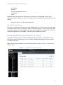
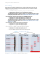
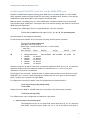
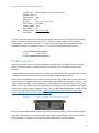
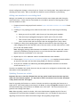
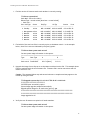
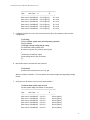
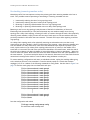
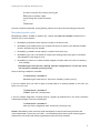
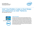
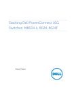
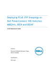
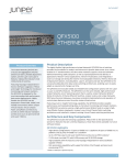
Stacking Dell Force10 MXL 10/40G Blade Switches Victor Teeter Network Enabled Solutions Team Stacking Dell Force10 MXL 10/40G Blade Switches This document is for informational purposes only and may contain typographical errors and technical inaccuracies. The content is provided as is, without express or implied warranties of any kind. © 2012 Dell Inc. All rights reserved. Dell and its affiliates cannot be responsible for errors or omissions in typography or photography. Dell, the Dell logo, and PowerEdge are trademarks of Dell Inc. Other trademarks and trade names may be used in this document to refer to either the entities claiming the marks and names or their products. Dell disclaims proprietary interest in the marks and names of others. July 2012| Rev 1.0 ii Stacking Dell Force10 MXL 10/40G Switches Contents Introduction ............................................................................................................. 3 Redundancy ........................................................................................................... 4 Failover roles ......................................................................................................... 4 Stacking LAG .......................................................................................................... 4 Enablement of LAG/LACP on blade servers ..................................................................... 4 Meta-data ............................................................................................................. 4 Restoring factory defaults .......................................................................................... 5 Constant stack configuration ...................................................................................... 5 Bare Metal Provisioning ............................................................................................. 6 Identifying physical units and ports in a stack .................................................................... 6 Port numbering ....................................................................................................... 7 Combining split 10GbE SFP+ ports into a single 40GbE QSFP+ port ......................................... 8 Master selection criteria .............................................................................................. 9 Manually selecting a Master during initial stack setup ........................................................ 9 Stacking scenarios .................................................................................................... 10 Creating the MXL stack ........................................................................................... 13 Adding new members to an existing stack .................................................................... 17 Updating firmware on a stack ................................................................................... 17 Un-stacking (removing member units) ......................................................................... 20 Renumbering stack units ......................................................................................... 21 Appendix A – Stacking scenarios ...................................................................................... 23 Appendix B – Port mapping ............................................................................................ 24 Appendix C - Network switch versions ............................................................................... 25 Figures Figure 1. Dell Force10 MXL (10/40G Ethernet) ................................................................... 3 Figure 2. I/O module overview from the CMC .................................................................... 6 Figure 3. Port mapping for QSFP+ ports............................................................................ 7 Figure 4. QSFP+ two 40GbE port expansion for the MXL ...................................................... 10 Figure 5. Stacking multiple MXL switches in a single M1000e ................................................ 12 Figure 6. Stacking MXL switches across multiple M1000e chassis using two ports between members 12 1 Stacking Dell Force10 MXL 10/40G Switches 2 Stacking Dell Force10 MXL 10/40G Switches Introduction Numerous Dell™ switches include a stacking feature that allows multiple physical switches to operate as a single logical switch, providing a consolidated interface for management. The Dell Force10 MXL 10/40Gb switch is the latest Dell switch with this feature. Up to six Dell Force10 MXL switches can be connected in a single stack using QSFP+ (40Gb) ports. A single switch (Master) in the stack controls all switches in the stack thereby allowing the user to manage and configure all member switches and ports using one IP address. This IP address is copied from the Master to the Standby when the Standby is created. If for any reason the Master fails and the Standby takes over as the Master, the IP address of the stack will remain the same, allowing continuous management of the stack. The new Master unit will also continue to use the original Master unit’s MAC address which helps to reduce disruptions to the network. When a failed Master re-joins the stack, it does so as a member (not a Master) unless a new Master has not had time to be elected. Up to four QSFP+ (40Gb) ports can be used for stacking on any member switch. Only two scenarios support using four ports. One uses all four ports in a daisy-chain stack topology containing only two switch members. The other uses a ring topology with two links between each member (see Figure 6). Three or four QSFP+ ports may also be used between each member in a daisy-chain topology containing only two member switches. The typical scenario uses one or two QSFP+ ports to connect stack members in a ring topology while allowing available QSFP+ ports for uplinks. Dell recommends a ring topology (connecting the first and last members to create a loop) for a more resilient stack that helps avoid stack splits. Stack splits are covered below in more detail. This document provides an easy to use step-by-step guide on how to configure stacking for the Dell Force10 MXL (Figure 1). Figure 1. Dell Force10 MXL (10/40G Ethernet) Note: The Dell Force10 MXL can only be stacked with other Dell Force10 MXL switches. Note: Only QSFP+ ports can be used for stacking and they must be in 40Gb mode. Stacking cannot be enabled on these ports when split into four 10Gb ports. An important advantage of stacking is that it provides a consolidated interface for management of multiple switches linked together. After a stack is deployed in the network, operators can easily add units to the stack as their port requirements increase, with minimal administrative overhead. 3 Stacking Dell Force10 MXL 10/40G Switches Additional stack members can immediately utilize existing configuration information such as routing and switching configurations, VLANs, ACLs, port profiles, and security certificates. Redundancy By connecting a cable from the last switch in a stack back to the first switch, the operator ensures that a stack has the protection of redundant paths for control and data traffic. Support for link aggregation groups (LAG) configured across multiple switches provides yet another layer of redundancy as well as adding bandwidth. This means that any single point of failure (a switch or a stack cable failure) will not affect the overall operation of the remaining stack elements. This type of stacking topology is referred to as a “ring topology”. The other stacking topology where the last and first switch are not connected is referred to as a daisy-chain topology stack. This type of stack is much less resilient and not recommended in most cases. Both topologies are mentioned several times in this document Failover roles If the stack Master fails (for example, loses power), it is removed from the stack topology. The Standby unit detects the loss of peering communication and takes ownership of the stack management, switching from Standby to Master. If a Standby was not set up by the administrator, the stack automatically triggers an election within the remaining units to select a new Master. While a new Master is being selected (either through election or pre-selection), a new Standy is also chosen from the remaining members based on the same criteria as a Master selection (priority, then highest MAC address). After the former Master switch recovers, despite having a higher priority or MAC address, it does not recover its Master role but instead take the next available role as Standy or Member. Stacking LAG When multiple links between stack members are used, the Dell Force10 MXL automatically bundles them into a single logical link, or LAG, providing higher stacking bandwidth and redundancy. The stacking LAG is established automatically without user configuration once all ports used in the LAG are set in stacking mode. The LAG can lose link or gain links simply by removing or inserting the cables. Enablement of LAG/LACP on blade servers Another benefit of stacking MXL switches is that it allows a blade server to create LAGs to the stacked switch. For example, if MXL switches are stacked in slots B1 and B2, then NICs on B1 and B2 on a given server could be configured for LAGs/LACP. Meta-data The actual stack configuration used to stack switches during power-up is read from meta-data, not from the startup configuration. It is applied at boot time prior to starting the switch firmware and reading the startup configuration. Stack information shown in the startup and running configurations is simply repeating information from the meta-data for the user’s knowledge. Therefore, if the startup configuration is deleted and the switch is reloaded, it will not clear the stacking configuration and the stack will remain intact after the reload. In order to remove the stacking configuration, the “no” command will need to be implemented for each of the stack-unit commands that were used to create the stack. 4 Stacking Dell Force10 MXL 10/40G Switches Another way to completely wipe out all configurations and return to factory defaults is to erase the meta-data (NVRAM) and delete the startup configuration by following the instructions in Restoring factory defaults below. Restoring factory defaults Usually a standalone MXL can be set to factory defaults simply by deleting the startup configuration and reloading the switch (Step 2). However, once an MXL has been stacked, additional steps are required in order to remove the stacking configuration from the NVRAM meta-data. To completely remove all configurations (including stacking) and return to factory defaults on any stack member: 1. Unplug the stacking cables connecting the switch to the rest of the stack. 2. From the console prompt of the removed switch, type delete startup-configuration and press enter, then reload the system. If prompted to save the configuration, enter “no”. 3. During reboot, press any key at the second prompt to get to the BOOT_USER # menu (the bootup process allows 5 seconds to press any key to get to this menu). 4. From the BOOT_USER # prompt, type enable admin to get into administrative mode. The default password is “ncorerulz”, which brings up the BOOT_ADMIN # prompt. 5. Type nvram erase <enter>. Then type reload <enter>. When the reload completes, the switch will be at factory defaults. Constant stack configuration A minimum stack configuration is always present on a stack-capable switch. Even if a switch has never been stacked with other switches, it is still considered a “stack of 1”, and therefore will always contain “stack-unit” lines in the running configuration. Here is an example configuration of a device that is not stacked. Note: FTOS starts numbering stack units at zero, so a single stack-unit 0 as shown below is in fact a stack unit of 1. FTOS#show running-config Current Configuration ... ! Version 8.3.16.0E0 ! Startup-config last updated at Thu May 3 11:49:39 2012 ! boot system stack-unit 0 primary system: A: boot system stack-unit 0 secondary system: A: boot system gateway 172.31.0.1 ! redundancy auto-synchronize full ! hostname FTOS ! username root password 7 d7acc8a1dcd4f698 privilege 15 ! stack-unit 0 provision MXL-10/40GbE ! interface TenGigabitEthernet 0/1 5 Stacking Dell Force10 MXL 10/40G Switches no ip address shutdown ! interface TenGigabitEthernet 0/2 no ip address --More-Additional stack-unit lines like the one below may be found in an unstacked MXL if one or more expansion modules are present. In order to use these ports for stacking the quad mode will need to be removed. stack-unit 0 port (41, 43, 49, 53) portmode quad Bare Metal Provisioning The system is configured for Bare Metal Provisioning (BMP) mode when it leaves the factory. Bare Metal Provisioning can be used to help configure a stack or a stand-alone system. With minimum effort, BMP can obtain IP address, running configuration and boot image information from a DHCP server. For more information regarding how to setup BMP, consult the Dell Force10 MXL User Guide. Identifying physical units and ports in a stack The Master will always have a blue LED illuminating steadily (not flashing). A stand-alone will also have the blue light illuminated since it is it’s own Master. Standby and Member units in the stack do not illuminate this light. Note: The CMC shows each Master in the chassis and the fabric (A1, A2, B1, B2, C1, or C2) where it is located. See 0. Figure 2. I/O module overview from the CMC 6 Stacking Dell Force10 MXL 10/40G Switches Port numbering When installed in a PowerEdge™ M1000e Enclosure, the MXL 10/40GbE external switch ports are numbered 33 to 56 from the bottom to the top of the switch (ports 1-32 are internal 10G ports): • 40GbE base-module (built-in) ports: In 2x40GbE mode of operation (default), the ports are numbered 33 and 37. • In 8x10GbE mode of operation, the ports are numbered 33 through 40. The 40GbE mode of operation is required for stacking. For information about how to change from 8x10GbE mode to 40GbE mode, refer to Combining split 10GbE SFP+ ports into a single 40GbE QSFP+ port below. • 2-Port 40-GbE QSFP+ expansion module operating in the default 8x10GbE mode: • In expansion slot 0, the ports are numbered 41 to 44 and 45 to 48. • In expansion slot 1, the ports are numbered 49 to 52 and 53 to 56. The 40GbE mode of operation is required for stacking. For information about how to change from 8x10GbE mode to 40GbE mode, refer to Combining split 10GbE SFP+ ports into a single 40GbE QSFP+ port below. • 2-Port 40-GbE QSFP+ expansion module operating in 40GbE mode: • In expansion slot 0, the ports are numbered 41 and 45. • In expansion slot 1, the ports are numbered 49 and 53. • 4-Port 10-GbE SFP+ or 10GBASE-T module (NOT USED FOR STACKING): • In expansion slot 0, the ports are numbered 41 to 44. • In expansion slot 1, the ports are numbered 49 to 52. Only one 10GBaseT expansion module can be installed per MXL. Figure 3. Port mapping for QSFP+ ports See Appendix B – Port mapping for a complete list of port numbers. 7 Stacking Dell Force10 MXL 10/40G Switches Combining split 10GbE SFP+ ports into a single 40GbE QSFP+ port The MXL 10/40GbE Switch supports splitting each 40GbE port on the base module or a 2-Port 40GbE QSFP+ expansion module into eight 10GbE SFP+ ports using a breakout cable. However, ports must be combined into single 40Gbe QSFP+ ports to operate in Stacking mode. Note: By default, the 40GbE ports on a 2-Port 40GbE QSFP+ expansion module come up in 8x10GbE (quad) mode as eight 10GbE ports. If these ports are to be used for stacking, they must be converted to 40GbE using the steps below. To combine four 10GbE split ports into a single 40GbE port, enter the command: FTOS(conf)# no stack-unit <0-5> port <33, 37, 41, 45, 49, 53> portmode quad Save and reload for the changes to take effect. To find the stack-unit number (0-5) of the stack-unit being viewed type the command: FTOS(conf)# do show system brief Stack MAC : 00:1e:c9:cc:bb:21 Reload Type : normal-reload [Next boot : normal-reload] -- Stack Info -Unit UnitType Status ReqTyp CurTyp Version Ports ---------------------------------------------------------------------------------------------------- 0 1 2 3 4 5 Management Member Member Member Member Member online MXL-10/40GbE not present not present not present not present not present MXL-10/40GbE 8.3.16.0E0 56 Valid port values are 33 and 37 if there are no expansion modules installed, and 41, 45, 49, and 53 for expansion module ports when expansion modules are installed. See Port numbering for more information on how ports are numbered. The last part of the command, “portmode quad” is required and typically converts the port to a split 10GbE SFP+ port. However, when preceding the command with the “no” option as in the example above, the ports are converted to a single 40GbE. To complete the conversion to 40GbE, save the configuration and reload the switch. FTOS# copy running-config startup-config FTOS# reload Display the current 40GbE or 4x10GbE mode of port operation using the following command: FTOS# show running-config Two different lines in the configuration can identify the port mode: 1. stack-unit 0 port 41 portmode quad This example shows port 41 is in quad mode, which means ports 41, 42, 43, and 44 are each 10GbE. Only the first port number (33, 37, 41, 45, 49, and 53) for each QSFP+ is 8 Stacking Dell Force10 MXL 10/40G Switches listed here when in port mode. If there is no “stack-unit” listing for the first port number, then the ports are not split and are running at 40GbE. 2. interface fortyGigE 0/33 : interface TenGigabitEthernet 0/41 Each individual port mode is listed further down in the configuration. If the interface is listed as fortyGigE then it may be used for stacking. If it is TenGigabitEthernet, then it may not be used for stacking. The command show interface status will also show which Ethernet mode each port is in and whether it is 10Gb (Speed = Auto) or 40Gb (Speed = 40000 Mbit) . If the port is configured as a stack port, then show interface status will not display any information about that port. Master selection criteria A Master is elected or re-elected based on the following considerations, in order: 1. The switch with the highest Priority at boot time. 2. The switch with the highest MAC address at boot time. 3. A unit is selected as Standby by the administrator, and a fail over action is manually initiated or occurs due to a Master unit failure. No record of previous stack mastership is kept when a stack loses power. As it reboots, the election process will once again determine the Master and Standby switches. As long as the Priority hasn’t changed on any members, the stack will retain the same Master and Standby. Note: Each stack members’ role (including the Master and Standby) can be defined by the user at any time by setting the Priority. If the entire stack is powered OFF and ON again, the unit that was the Master before the reboot will remain the Master after the stack resumes operation. However, when a stack is powered on, all members are in “sleep” mode for 5 seconds while waiting on the previous Master to join the stack. If the previous Master fails to join within 5 seconds, the remaining members (including the Standby) elect a new Master. Manually selecting a Master during initial stack setup When using two or more switches to initially create a stack, the Master is chosen based on the highest Priority first, then highest MAC address. To find the MAC address of a switch, type show system from a CLI prompt: FTOS#show system Stack MAC : 00:1e:c9:cc:bb:21 Reload Type : normal-reload [Next boot : normal-reload] -- Unit 0 -Unit Type : Management Unit Status : online Next Boot : online Required Type : MXL-10/40GbE - 34-port GE/TE/FG (XL) 9 Stacking Dell Force10 MXL 10/40G Switches Current Type : MXL-10/40GbE - 34-port GE/TE/FG (XL) Master priority : 0 Hardware Rev : X00 Num Ports : 56 Up Time : 1 wk, 3 day, 23 hr, 5 min FTOS Version : 8.3.16.0E0 Jumbo Capable : yes POE Capable : no Burned In MAC : 00:1e:c9:cc:bb:21 No Of MACs :3 To force a particular switch to become the Master during stack creation, be sure that switch has the highest Priority of all switches joining the stack. The switch with the highest Priority number is elected Master. The default Priority is 0. Priorities for the stack-unit can be configured using the command 'stack-unit <unit-number> priority <1-14>' from the configuration mode as follows: FTOS(conf)#stack-unit 0 priority ? <1-14> Priority Value FTOS(conf)#stack-unit 0 priority 12 Stacking scenarios The following section presents a variety of examples stacking Dell Force10 MXL switches, providing step-by-step CLI commands. Consult the table of contents for a list of examples covered in this document. It is most important to have all switches on the same firmware version prior to stacking them. Be sure to update all switches to be used with the latest firmware to obtain the best results. Unless noted, the example scenarios assume the switches are using the MXL built-in external ports 33 and 37 and that no expansion modules are installed providing additional external ports. However, once a QSFP+ expansion module is set to 40Gb mode, it can then be set to stacking mode just like the builtin QSFP+ ports. Each QSFP+ expansion module (Figure 2) installed provides two additional ports which can be used for stacking when in 40Gb port mode. Use the “show system stack-port“ command to see if any ports are already in stacking mode. Error! Reference source not found.Error! Reference source not found.Error! Reference source not found. Figure 4. QSFP+ two 40GbE port expansion for the MXL Dell Force10 MXL modular blade switches may only be stacked using QSFP+ ports in 40GbE port mode. QSFP+ built-in ports are set to 40Gb by default while expansion module QSFP+ ports are set to 10Gb ports by default. To change a port from 10Gb mode to 40Gb mode, use the command 10 Stacking Dell Force10 MXL 10/40G Switches FTOS(conf)#no stack-unit 0 port p portmode quad Please save and reload for the changes to take effect. where p is the port to be converted. Refer to the section Combining split 10GbE SFP+ ports into a single 40GbE QSFP+ port for more details on how to use this command. Note: MXL stacking support QSFP+ cable lengths at distances of up to 7m. Dell offers cables in lengths of 1m, 3m, 5m, and 7m that can be used for this purpose. The Dell Force10 MXL supports stacking across multiple M1000e chassis (known as vertical stacking). That means it is possible to have six M1000e chassis’, each one having an MXL installed with all six MXL switches being members of the same stack. Figure 4 shows the connectivity between the stack members in M1000e chassis slots A2, B2, and C2 using a single 40Gb stacking port. Figure 6 5 shows the connectivity between stack members across multiple M1000e chassis using two stacking ports between members. All slots (A1, A2, B1, B2, C1, C2) in the M1000e are supported, and any of these slots can be used to stack along with any other slot or set of slots. There are no limitations as to which slots can be used and the number of chassis which can be used. The only limitation is six MXL devices. The follow lists possible scenarios: Stacking two to six Dell Force10 MXL switches using any combination of slots A1, A2, B1, B2, C1 and C2 in a single chassis. Stacking two to six Dell Force10 MXL switches using any combination of slots A1, A2, B1, B2, C1 and C2 in multiple chassis’. Examples: Stacking six Dell Force10 MXL switches across six M1000e chassis , using slot A1 in first chassis, B2 in second, C1 in third, A1 in fourth, B1 in fifth, and B1 in sixth. Stacking six Dell Force10 MXL switches across two M1000e chassis, using slots B1, B2 and C2 in chassis 1 and slots B2, C1, and C2 in chassis 2. Stacking three Dell Force10 MXL switches across two M1000 chassis, using two slots in the first chassis and only one slot in the second. Any other way of stacking up to six MXL switches in up to six chassis. Note: It is also possible to have multiple stacks in a single chassis (horizontal stacking) or across multiple chassis’ (vertical stacking). 11 Stacking Dell Force10 MXL 10/40G Switches Figure 5. CMC 2 KVM CMC2 1 2 3 4 5 7 8 1 A1 B1 2 3 4 6 9 5 C2 B2 49-56 LNK LNK LNK 37-40 37-40 37-40 ACT ACT ACT LNK LNK LNK 33-36 33-36 33-36 CONSOLE ACT ACT ACT CONSOLE A2 20 1 2 18 3 18 1 3 17 4 17 3 CONSOLE C1 CMC2 2 3 5 7 6 8 2 3 C2 4 9 5 Gb 6 B2 A2 49-56 20 20 20 2 2 1 2 1 1 19 19 19 18 18 41-48 18 4 4 3 4 3 17 17 17 3 CONSOLE CONSOLE CONSOLE CONSOLE 1 Gb 2 CMC iKVM CMC B1 KVM 1 4 1 A1 ACT CONSOLE 2 33-36 CONSOLE CONSOLE 1 Gb LNK 17 4 2 1941-48 Gb ACT 4 20 1 2 37-40 19 18 1 Gb LNK 19 49-56 ACT CONSOLE A2 33-36 ACT CONSOLE 20 2 Gb 6 LNK 33-36 CONSOLE CONSOLE 9 5 B2 ACT 17 17 3 4 37-40 4 3 LNK 3 LNK 17 4 ACT 3 3 6 8 2 CMC1 CMC2 2 5 7 C2 PowerConnect M8024-k 41-48 18 C1 Force10M8024-k MXL 10/40GbE PowerConnect 19 37-40 4 1 1 LNK 18 B1 KVM 1 4 1 A1 PowerConnect M8024-k 2 19 2 PowerConnect M8024-k 1 18 1 Gb Force10 MXL 10/40GbE PowerConnect M8024-k 20 2 2 19 Gb PowerConnect M8024-k 20 20 2 PowerConnect M8024-k Force10 MXL PowerConnect M8024-k PowerConnect M8024-k 10/40GbE PowerConnect M8024-k 49-56 1 Gb CMC Gb 6 CMC 9 5 B2 M1000e Blade Chassis 4 M1000e Blade Chassis 3 iKVM 3 6 8 2 CMC1 CMC2 2 5 7 C2 M1000e Blade Chassis C1 CMC iKVM CMC B1 KVM 1 4 1 A1 41-48 Stacking MXL switches across multiple M1000e chassis using two ports between members CMC1 2 Force10 MXL 10/40GbE Force10 MXL 10/40GbE Force10 MXL 10/40GbE 41-48 CONSOLE 1 Gb 2 A2 49-56 41-48 Gb 1 Gb MXL Stack C1 49-56 Figure 6. Gb 6 Dell M1000e Blade Chassis 1 Gb iKVM CMC1 Gb CMC Stacking multiple MXL switches in a single M1000e Figure 6 shows three MXL switches, each in slot C2 of three different M1000e chassis (vertical stacking), and all three wired for stacking using two links. A typical scenario, like this one, uses either one or two links between members. A QSFP+ expansion module is required when using two links between switches in a stack with a ring topology as shown. The Dell M1000e Server Chassis includes a management console port on the CMC that allows allows management of each module from a single serial connection to the chassis. For more information, see the Dell Blade Server CMC User's Guide at http://support.dell.com/support/edocs/software/smdrac3/cmc/index.htm. 12 Stacking Dell Force10 MXL 10/40G Switches For this example the built-in ports 33 and 37 and the expansion ports 41 and 45 are used as shown in the above figure. For each switch in the stack, two cables are run from stacking ports on a switch to the two stacking ports on the next switch. This process is repeated until all of the devices are connected. To complete the ring topology for the stack, two stacking ports on the last switch are connected to two stacking port on the first switch. Connecting additional cables in parallel will increase the stacking bandwidth. Dell recommends that you connect the stack in a ring topology for resiliency and also that you use the same number of ports between peers in the stack. For example, do not use two cables between switches 1 and 2, and 2 and 3, but then only one cable to connect 3 and 1. Note: Up to four ports per MXL can be used to create a stack. All four ports on a member could be connected in parallel to another stack peer to create a stack of two members. Three ports could also be used in parallel to create a stack with only two members. To create a stack with three or more members, use 1 or 2 links between each member. Creating the MXL stack Prepare individual switches to be stacked 1. Identify all switches to be used as members of the stack, and upgrade each (as standalone MXL 10/40GbE switches) to the same firmware version. 2. Each MXL switch should be powered up with the default configuration. 3. Once the initial switch configuration is complete and the individual MXL 10/40GbE switches are powered up and fully operational, they are then ready to be stacked using the instructions below. Each 40GbE Interface corresponds to a stack-group, which is shown in the output of "show system stack-unit 0 stack-group" command. Use the “show inventory optional-module” command to see what expansion modules are installed. Example: FTOS#show system stack-unit 0 stack-group Stack group Ports -----------------------------------0 0/33 1 0/37 4 0/49 5 0/53 FTOS#show inventory optional-module Unit Slot Expected Inserted Next Boot Power ----------------------------------------------------------------0 0 SFP+ SFP+ AUTO Good 0 1 QSFP+ QSFP+ AUTO Good 13 Stacking Dell Force10 MXL 10/40G Switches In this example, stack-groups 0 and 1 correspond to the base MXL interfaces 33 and 37. Stack-groups 4 and 5 correspond to the two 40G QSFP+ expansion module interfaces inserted in slot 1. Since stacking MXL switches does not use 10Gig Interfaces, there are no stack-groups associated with the SFP+ or 10GbaseT port that may be installed. Those modules and ports are only used for uplinks on the MXL switch. Note: In this example, since an SFP+ expansion module was inserted in slot 0 during boot up, stackgroups 2 and 3 are not available. Note: If we had the SFP+ module present in Slot 1, and the QSFP+ module present in Slot 0, then the stack-groups 4 and 5 would be unavailable, and the stack-groups 2 and 3 would be available, corresponding to interfaces 0/41 and 0/45. Note: Activatation of the ports to be used for stacking (using the no shutdown command) isn’t necessary on the ports to be used for stacking. Configuring priority and stack-group Using the commands below, configure the Priorities and stack-groups for each of the MXL 10/40GbE Switches. Setting the Priority will determine which switch will become the management (Master) switch. The switch with the highest priority number is elected Master. The default Priority is 0. Priorities for the stack-unit can be configured using the command 'stack-unit <unit-number> priority <1-14>' from the configuration mode as follows: FTOS(conf)#stack-unit 0 priority ? <1-14> Priority Value FTOS(conf)#stack-unit 0 priority 12 Note: It is best practice to assign Priority values to all switches before stacking them in order to acquire and retain complete control over each units role in the stack. Stack-groups (below) are easier to think of simply as “stack ports.” For example, using the stackgroup 0 command simply turns the lower port (port 33) into a stacking port, stack-group 1 command turns the next port (port 37) into a stacking port, and so on. See Figure 3 for a complete list of stacking-group mappings. The stack-group (port) for each stack-unit are configured using the command 'stack-unit <unit-no> stack-group <stack-group-id>' from the configuration mode as follows: FTOS(conf)#stack-unit 0 stack-group 0 FTOS(conf)#02:26:05: %STKUNIT0-M:CP %IFMGR-6-STACK_PORTS_ADDED: Ports Fo 0/33 have been configured as stacking ports. Please save and reload for config to take effect Continue to run the stack-unit 0 stack-group <1-5> command to add additional stack ports to the switch, using the stack-group mapping shown in Figure 3. 14 Stacking Dell Force10 MXL 10/40G Switches Maximum stack-group per unit A maximum of 4 stack-groups per unit can be configured. In a ring topology, that would be 2 stackgroups in each direction, i.e 80Gbps stacking bandwidth. In a two unit stack, a maximum of 4 stackgroups between the two units (i.e 160Gbps stacking bandwidth) is allowed. Trying to configure more than 4 stack-groups results in the error shown here. FTOS(conf)#do show system stack-unit 1 stack-group configured Configured stack groups in stack-unit 1 -----------------------------------------0 1 2 3 FTOS(conf)#stack-unit 1 stack-group 4 % Error: Max stacking bandwidth for a unit is reached. Cabling the stack After setting these values save the configuration on each switch and reload each switch. Once all switches to be used in the stack have reloaded, attach the stacking cables in a supported topology using the MXL 40G-QSFP+ ports. It is recommended to attach the Master and Standby (based on priority or MAC address) first, then attach cables to the other members. As each cable is attached and each unit joins the stack for the first time, notice that the first available Unit-ID (0-5) is assigned to that unit, and the configuration for that unit is added into the running-configuration of the stack. Upon subsequent reloads, the unit-ID is retained by each stack member. If a new member with a higher Priority than the current Master joins the stack, it will become the Master of that stack. As cables are added and units join, the stack is dynamically built with the highest priority switch becoming or staying the Master. The fastest and most efficient way to build the stack is to connect the Master and Standby first so the stack will not go into a Master re-election when it finds the higher Priority/MAC. Validation Issue the show system brief command to see the unit IDs present in the stack. FTOS#show system brief Stack MAC : 00:1e:c9:f1:00:7b Reload Type : jump-start [Next boot : normal-reload] -- Stack Info -- Unit UnitType Status ReqTyp CurTyp Version Ports --------------------------------------------------------------------------------------------------0 Management online MXL-10/40GbE MXL-10/40GbE 8.3.16.0E0 56 1 Standby online MXL-10/40GbE MXL-10/40GbE 8.3.16.0E0 56 2 Member online MXL-10/40GbE MXL-10/40GbE 8.3.16.0E0 56 3 Member online MXL-10/40GbE MXL-10/40GbE 8.3.16.0E0 56 15 Stacking Dell Force10 MXL 10/40G Switches 4 Member 5 Member online online MXL-10/40GbE MXL-10/40GbE MXL-10/40GbE MXL-10/40GbE 8.3.16.0E0 56 8.3.16.0E0 56 Issue show system stack-port status command to see the topology and link status for each port. FTOS#show system stack-port status Topology: Daisy chain Interface Link Speed Admin Link Trunk (Gb/s) Status Status Group ---------------------------------------------------------------------------0/33 40 up up 0/37 40 up up 0/41 40 up down 0/45 40 up down 1/33 40 up up 1/37 40 up up 1/41 40 up down 1/45 40 up down 2/33 40 up down 2/37 40 up up 2/41 40 up down 2/45 40 up down 3/33 40 up down 3/37 40 up up 3/41 40 up down 3/45 40 up down : : : : Note: Each stack members’ role (including the Master and Standby) can be redefined by the user at any time by setting the Priority values and reloading the stack. Logical provisioning of a unit in a stack If desired, a stack-unit number can be pre-allocated and applied to an MXL switch added to the stack at a later date. This pre-configuration is stored on the Master switch and applied once the stack unit is added. When you provision a unit number for an MXL 10/40GbE Switch: The base-module ports on the switch (ports 33 and 37/stack groups 0 and 1) are pre-configured for 40GbE operation. The 40GbE ports on FlexIO expansion modules (ports 41 and 45 in slot 0; ports 49 and 53 in slot 1) are pre-configured for 4x10GbE (quad mode) operation. Once logical provisioning of a unit has been applied using the commands below, configurations can be made on that unit as if it were an actual physical unit. FTOS(conf)#stack-unit 1 provision ? MXL-10/40GbE 34-port GE/TE/FG (XL) FTOS(conf)#stack-unit 1 provision MXL-10/40GbE 16 Stacking Dell Force10 MXL 10/40G Switches Certain configuration changes on the unit such as “fanout” and “stack-groups” may require saving and reloading the entire stack. Refer to the MXL User Guide for more information on provisioning. Adding new members to an existing stack Adding a new member into an existing stack is achieved with the same simple tasks used during the initial stack setup. If more than one new member is to be added, repeat the following steps to add one new member at a time. 1. Prepare the switch using steps found in section Prepare individual switches to be stacked found on page 13. 2. If adding to a ring topology stack, cable the new switch into the stack using the following steps: a. Unplug one end of any QSFP+ cable from any of the existing stack members. b. Take the end just unplugged and plug into a QSFP+ port of the new switch. c. Take a second (new) cable and plug one end into the other QSFP+ port of the new switch, and the other end into the port that was unplugged from in step 1 above. 3. If adding to a daisy-chain topology stack, cable the new switch into the stack using a new cable, plugging one end into the QSFP+ port of the new switch, and the other end into a stack port on the end member switch. Note: Unplugging stackings cables between two members of a daisy-chain stack will create a stack split, immediately causing the switch or set of switches that were separated from the Master to become a new Master of it’s own stack. 4. Repeat step 2 or 3 for additional cables to be added between stack members. 5. Follow steps in Configuring priority and stack-group on page 14 to complete the stack addition. At the end of this step, only the switch being added will need to be reloaded. 6. Verify the new member was added using the show system brief command from the Master switch as shown on page 15. Once the new members have joined the stack, they are ready to be configured to include VLANs, LAGs, data cables to other equipment, etc. Updating firmware on a stack Important: Be sure to check the Release Notes and any special install instructions that may have come with new firmware updates. It is important to follow instructions found in those documents if they deviate from this white paper. Steps for upgrading the firmware on a stack of switches are similar to upgrading the firmware on a single switch. After downloading a new image to the Master by using the upgrade command in the CLI, the downloaded image is distributed to all member units of the stack. The instructions below will guide the user through these steps. Note: When upgrading a stack of switches, allow extra time between upgrade steps for files and configurations to be copied from the Master to each member unit. It is possible for the process of upgrading a switch stack to take a few minutes longer than upgrading a single switch. 17 Stacking Dell Force10 MXL 10/40G Switches 1. Find the version of firmware each stack member is currently running. FTOS#show system brief Stack MAC : 00:1e:c9:cc:bb:1b Reload Type : normal-reload [Next boot : normal-reload] -- Stack Info -Unit UnitType Status ReqTyp CurTyp Version Ports ------------------------------------------------------------------------------------------------0 Standby online MXL-10/40GbE MXL-10/40GbE 8.3.16.0E0 56 1 Management online MXL-10/40GbE MXL-10/40GbE 8.3.16.0E0 56 2 Member online MXL-10/40GbE MXL-10/40GbE 8.3.16.0E0 56 3 Member online MXL-10/40GbE MXL-10/40GbE 8.3.16.0E0 56 4 Member online MXL-10/40GbE MXL-10/40GbE 8.3.16.0E0 56 5 Member online MXL-10/40GbE MXL-10/40GbE 8.3.16.0E0 56 2. Find which of the two boot files is currently active on the Master switch. In the example below, the A file is active as indicated by the [boot] option. FTOS#show boot system stack-unit all Current system image information in the system: ====================================================== Type Boot Type A B -----------------------------------------------------------------------------Stack-unit 0 FLASH BOOT 8.3.15.0[boot] 8.2.1.0 3. Upgrade the image from a tftp server to the Master switches inactive file. This example shows B will be replaced with the new firmware file. Firmware file A not be overwritten and will remain active for now. Caution: The command below may take several minutes to complete and may appear to be locked up during this time. FTOS#upgrade system tftp://10.10.10.1/FTOS-XL-8-3-16-0.bin b: !!!!!!!!!!!!!!!!!!!!!!!!!!!!!!!!!!!!!!!!!!!! 31972525 bytes successfully copied System image upgrade completed successfully. Upgrade system image for all stack-units [yes/no]: yes !!!!!!!!!!!!!!!!!!!!!!!!!!!!!!!!!!!!!!!!!!!!!!!!!!!!!!!!!!!!!!!!!!!!!!!!!!!!!!!!!!!!!!!!!!!!!!! !!!!!!!!!!!!!!!!!!!!!!!!!!!!!!!!!!!!!!!!!!!!!!!!!!!!!!!!!!!!!!!!!!!!!!!!!!!!!!!!!!!!!!!!!!!!!!! Image upgraded to all 4. Verify the new firmware was copied to all stack members. FTOS#show boot system stack-unit all Current system image information in the system: 18 Stacking Dell Force10 MXL 10/40G Switches ============================================= Type Boot Type A B ---------------------------------------------------------------Stack-unit 0 FLASH BOOT 8.3.15.0[boot] 8-3-16-0 Stack-unit 1 FLASH BOOT 8.3.15.0[boot] 8-3-16-0 Stack-unit 2 FLASH BOOT 8.3.15.0[boot] 8-3-16-0 Stack-unit 3 FLASH BOOT 8.3.15.0[boot] 8-3-16-0 Stack-unit 4 FLASH BOOT 8.3.15.0[boot] 8-3-16-0 Stack-unit 5 FLASH BOOT 8.3.15.0[boot] 8-3-16-0 5. Configure the stack to boot to the new firmware file (B in this example), then save the configuration. FTOS#config FTOS(conf)#boot system stack-unit all primary system b: FTOS(conf)#exit FTOS#copy running-config startup-config File with same name already exist. Proceed to copy the file [confirm yes/no]: yes ! 11910 bytes successfully copied Synchronizing data to peer Stack-unit !!!! ... 6. Reload the stack to activate the new firmware. FTOS#reload Proceed with reload [confirm yes/no]: yes Wait for reload to complete. This may take a few minutes longer than upgrading a single switch. 7. Verify the new firmware is active on all stack members. FTOS#show boot system stack-unit all Current system image information in the system: ============================================= Type Boot Type A B ---------------------------------------------------------------Stack-unit 0 FLASH BOOT 8.3.15.0 8-3-16-0[boot] Stack-unit 1 FLASH BOOT 8.3.15.0 8-3-16-0[boot] Stack-unit 2 FLASH BOOT 8.3.15.0 8-3-16-0[boot] Stack-unit 3 FLASH BOOT 8.3.15.0 8-3-16-0[boot] Stack-unit 4 FLASH BOOT 8.3.15.0 8-3-16-0[boot] Stack-unit 5 FLASH BOOT 8.3.15.0 8-3-16-0[boot] 19 Stacking Dell Force10 MXL 10/40G Switches Un-stacking (removing member units) Minimizing traffic flow interruptions is always the primary goal when removing member units from a stack. Four possible scenarios pertaining to unstacking or removing a member unit are: 1. 2. 3. 4. Intentionally reducing the size of a ring topology stack Intentionally reducing the size of a daisy-chain topology stack Removing or replacing a failed member unit on a ring topology stack Removing or replacing a failed member unit on a daisy-chain topology stack Removing a unit from a ring topology is easy because of the built-in redundancy of the stack. Eliminating links (intentionally or from failure) between any two members simply turns the ring topology into a daisy-chain topology, allowing all traffic to continue through the stack. After physically removing a stack member, simply connect the two sets of stack ports on the two switches that were previously attached to the switch that was removed. The stack will resync while regaining a resilient ring topology. On a daisy-chain topology stack, after physically removing an end member unit (one that is only connected to one other member), there is nothing else to do. However, when removing a member unit from the middle of a daisy-chain stack, there are a few additional steps required to prevent a split stack. A split stack occurs on a daisy-chain topology when any link (or switch) in the middle of the stack fails or is removed. The side of the split that has the Master will remain intact, while the side of the split with no Master will detect its Master is lost and therefore re-elects a new Master. When this occurs it leaves two stacks. Both stacks now share the same IP address which will cause problems if on the same network. To prevent stack split issues on the network, disconnect one of the stacks from the network and reconfigure the stack to a new IP address using the Master console port. To remove stacking configurations and return to individual switches, unplug the stacking cables going to the switch(es) that are to be unstacked. From the console prompt of a switch that has been unplugged, run all or a subset of the following commands in config mode. Use the chart in Figure 3 on page 7 to find the stack-group that correlates with each port: FTOS(conf)#no FTOS(conf)#no FTOS(conf)#no FTOS(conf)#no FTOS(conf)#no FTOS(conf)#no FTOS(conf)#no FTOS(conf)#no FTOS(conf)#no FTOS(conf)#no FTOS(conf)#no FTOS(conf)#no stack-unit stack-unit stack-unit stack-unit stack-unit stack-unit stack-unit stack-unit stack-unit stack-unit stack-unit stack-unit 0 0 0 0 1 1 1 1 2 2 2 2 stack-group 0 stack-group 1 stack-group 2 stack-group 3 stack-group 0 stack-group 1 stack-group 2 stack-group 3 stack-group 0 stack-group 1 stack-group 2 stack-group 3 : : FTOS(conf)#no stack-unit 5 stack-group 2 FTOS(conf)#no stack-unit 5 stack-group 3 FTOS(conf)#exit Save the configuration and reload. FTOS#copy running-config startup-config File with same name already exist. 20 Stacking Dell Force10 MXL 10/40G Switches Proceed to copy the file [confirm yes/no]: yes ! 9582 bytes successfully copied Synchronizing data to peer Stack-unit !!!! .... FTOS#reload Once the reload has completed, unplug stacking cables from all ports where stacking was removed. Renumbering stack units Renumbering a Master, Standby or member unit, requires the stack-unit renumber command and a reload of one or more switches: Renumbering the Master switch requires a reload of the entire stack Renumbering the Standby switch only requires that switch to reload, but a different member switch is elected as the new Standby Renumbering a member switch requires a reload of that switch only Renumbering any unit in the middle of a daisy-chain topology stack may require a stack-split and subsequent stack-merge to occur Renumbering a switch to a number already assigned to another stack unit results in following error message: “Renumbering will reset the unit. Warning: Interface configuration for current unit will be lost! Proceed to renumber [confirm yes/no]:” Use the following command to renumber: FTOS#stack-unit 1 renumber 5 Renumbering will reset the unit. Proceed to renumber [confirm yes/no]: If the new number which we want to assign is already used by an existing member of the stack, the below error will occur. FTOS#stack-unit 1 renumber 5 % ERROR: stack unit 5 already exists. If the new number assignment is already used by a logically provisioned unit in the stack, the below confirmation message to overwrite is displayed. FTOS#stack-unit 1 renumber 5 Stack unit 5 has configuration data. Overwrite? [confirm yes/no]: Caution: Renumbering stack units may hinder management scripts and monitoring software that collects data based on particular port traffic. Use renumbering with caution when monitoring ports and be aware that scripts and monitoring parameters may need to be modified. 21 Stacking Dell Force10 MXL 10/40G Switches For more information on stacking the Dell Force10 MXL, please refer to the Stacking chapter of the Dell Force10 MXL User Guide available at http://www.dell.com/manuals. 22 Stacking Dell Force10 MXL 10/40G Switches Appendix A – Stacking scenarios 23 Stacking Dell Force10 MXL 10/40G Switches Appendix B – Port mapping 24 Stacking Dell Force10 MXL 10/40G Switches Appendix C - Network switch versions Version information for the network switches used in creating this document are as follows: Network switch Dell Force10 XML Software version 8.3.16.0, E8.3.16.163, E8.3.16.0E0 25