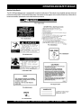
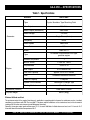
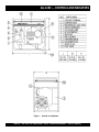
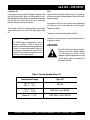
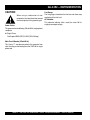
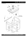
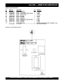
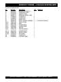
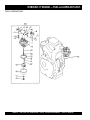
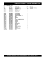
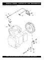
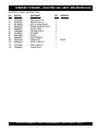
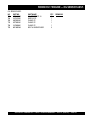
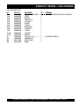
1
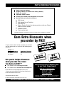
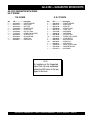
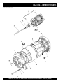
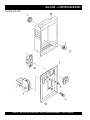
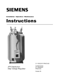
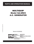
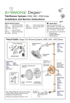
PARTS AND OPERATION MANUAL
© COPYRIGHT 2001, MULTIQUIP INC.
MULTIQUIP
Model GA-2.3R2
A.C. GENERATOR
Revision #2 (03/05/01)
MULTIQUIP INC..
PARTS DEPARTMENT:
18910 WILMINGTON AVE.
800-427-1244
CARSON, CALIFORNIA 90746 FAX: 800-672-7877
SERVICE DEPARTMENT/TECHNICAL ASSISTANCE:
310-537-3700
800-421-1244
800-478-1244
FAX: 310-537-3927
FAX: 310-631-5032
E-mail:[email protected] • www:multiquip.com
Atlanta • Boise • Dallas • Houston • Newark
Montreal, Canada • Manchester, UK
Rio De Janiero, Brazil • Guadalajara, Mexico
PAGE 2 — GA-2.3R2 A.C. GENERATOR— PARTS & OPERATION MANUAL — REV. #2 (03/05/01)
HERE'S HOW TO GET HELP
PLEASE HAVE THE MODEL AND SERIAL NUMBER
ON-HAND WHEN CALLING
PARTS DEPARTMENT
800-427-1244 or 310-537-3700
FAX: 800-672-7877 or 310-637-3284
SERVICE DEPARTMENT/TECHNICAL ASSISTANCE
800-478-1244 or 310-537-3700
FAX: 310- 537-4259
WARRANTY DEPARTMENT
888-661-4279, or 310-661-4279
FAX: 310- 537-1173
MAIN
800-421-1244 or 310-537-3700
FAX: 310-537-3927
GA-2.3R2 A.C. GENERATOR — PARTS & OPERATION MANUAL — REV. #2 (03/05/01) — PAGE 3
TABLE OF CONTENTS
Here's How To Get Help ............................................ 3
Table Of Contents ..................................................... 4
Parts Ordering Procedures ....................................... 5
Rules For Safe Operation ......................................... 6
Operation and Safety Decals .................................... 7
Specifications ............................................................ 8
General Information .................................................. 9
Multiquip GA-2.3R2 —
AC Generator
Robin EH-17 Engine
Crankcase Assembly .........................................34-35
Crankshaft & Piston Assembly ...........................36-37
Intake & Exhaust Assembly ...............................38-39
Governor Assembly ...........................................40-41
Cooling & Starting Assembly .............................42-43
Fuel & Lubricant Assembly ................................44-45
Electric Coil Assembly And Spark Plug ..............46-47
Oil Sensor Assembly ..........................................48-49
Fuel Strainer ......................................................50-51
Terms and Conditions Of Sale — Parts .................. 52
Controls and Indicators ........................................... 10
Installation ............................................................... 11
Pre-Setup ........................................................... 12-13
Instrumentation ....................................................... 14
Load Application ..................................................... 15
Operating Instructions............................................. 16
Maintenance ........................................................... 17
Preparation For Long Term Storage ....................... 18
Wiring Diagram ....................................................... 19
Troubleshooting (Engine) ................................... 20-21
Troubleshooting (Generator) ............................. 22-23
Explanation Of Codes In Remarks Column ............ 24
Suggested Spare Parts ........................................... 25
Generator Assembly .......................................... 26-27
Control Box Assembly ........................................ 28-29
Pipe Frame Assembly ........................................ 30-31
Name Plate And Decals ..................................... 32-33
NOTE
Specification and part number
are subject to change without
notice.
PAGE 4 — GA-2.3R2 A.C. GENERATOR— PARTS & OPERATION MANUAL — REV. #2 (03/05/01)
PARTS ORDERING PROCEDURES
n
n
n
n
n
n
n
Dealer account number
Dealer name and address
Shipping address (if different than billing address)
Return fax number
Applicable model number
Quantity, part number and description of each part
Specify preferred method of shipment:
•
•
•
•
UPS Ground
UPS Second Day or Third Day*
UPS Next Day*
Federal Express Priority One (please provide us with your Federal
Express account number)*
•
•
Airborne Express*
Truck or parcel post
*Normally shipped the same day the order is received, if prior to 2PM west coast time.
Earn Extra Discounts when
you order by FAX!
All parts orders which include complete part numbers
and are received by fax qualify for the following extra
discounts:
Number of
line items ordered
1-9 items
Additional Discount
3%
10+ items**
5%
Get special freight allowances
when you order 10 or more
line items via FAX!**
n
n
UPS Ground Service at no charge for freight
PS Third Day Service at one-half of actual freight cost
No other allowances on freight shipped by any other carrier.
**Common nuts, bolts and washers (all items under $1.00 list price)
do not count towards the 10+ line items.
*DISCOUNTS ARE SUBJECT TO CHANGE*
count
s
i
D
x
Fa
A
Extra
tic US
s
e
m
for Do
Only
s
r
e
l
a
De
Now! Direct TOLL-FREE access
to our Parts Department!
Toll-free nationwide:
800-421-1244
Toll-free FAX:
800/6-PARTS-7 • 800-672-7877
Fax order discount and UPS special programs revised June 1, 1995
GA-2.3R2 A.C. GENERATOR — PARTS & OPERATION MANUAL — REV. #2 (03/05/01) — PAGE 5
RULES FOR SAFE OPERATION
CAUTION:
Failure to follow instructions in this manual
may lead to serious injury or even death! This
equipment is to be operated by trained and
qualified personnel only! This equipment is
for industrial use only.
The following safety guidelines should always be used when
operating the GA-2.3R2 Generator:
GENERAL SAFETY
■ DO NOT operate or service this equipment before reading
this entire manual.
■ Provide adequate ventilation when operating the generator.
DO NOT operate the generator in any enclosed or narrow
space. The generator's gasoline engine gives off DEADLY
monoxide gas.
■ NEVER operate the generator in an explosive atmosphere or
near combustible materials. An explosion or fire could result
causing severe bodily harm or even death.
■ Always make sure that the generator is secure on level ground
so that it cannot slide or shift around, endangering workers.
Also keep the immediate area free of bystanders.
CAUTION:
■ High Temperatures – Allow the machine
and engine to cool before adding fuel or
performing service and maintenance
functions. Contact with hot components can
cause serious burns.
■ This equipment should not be operated by persons under 18
years of age.
■ NEVER operate this equipment without proper protective
clothing, shatterproof glasses, steel-toed boots and other
protective devices required by the job.
■ This generator is a source of providing LETHAL high voltages.
Never permit unqualified personnel-especially children to
operate the generator.
■ Always refuel in a well-ventilated area, away from sparks and
open flames.
■ Always use extreme caution when working with flammable
liquids. When refueling, stop the engine and allow it to cool.
DO NOT smoke around or near the machine. Fire or explosion
could result from flames or sparks, or if fuel is spilled on a hot
engine.
■ This generator is equipped with a ground terminal for your
protection. Always complete the grounding path from the
generator to an external grounding source.
■ NEVER operate this generator, or handle any electrical
equipment while standing in water, while bare foot, while
hands are wet, or in the rain. Dangerous electrical shock
could occur causing severe bodily harm or even death.
■ Keep electrical cords in good condition. Worn, bare or frayed
wiring can cause electrical shock, thus causing bodily harm
or even death.
■ This generator requires an adequate free flow of cooling air.
Never operate the generator in any enclosed or narrow area
where free flow of the air is restricted. If the air flow is restricted
it will cause serious damage to the generator and may cause
injury to people.
CAUTION:
Emergencies
■ Always know the location of the nearest fire
extinguisher and first aid kit. Know the
location of the nearest telephone. Also know
the phone numbers of the nearest ambulance,
doctor and fire department. This information
will be invaluable in the case of an emergency.
Maintenance Safety
■ NEVER lubricate components or attempt service on a running
machine.
■ Always allow the machine a proper amount of time to cool
before servicing.
■ Keep the machinery in proper running condition.
■ Fix damage to the machine immediately and always replace
broken parts.
■ Dispose of hazardous waste properly. Examples of potentially
hazardous waste are used motor oil, fuel and fuel filters.
■ DO NOT use food or plastic containers to dispose of
hazardous waste.
■ DO NOT pour waste, oil or fuel directly onto the ground,
down a drain or into any water source.
■ NEVER touch the hot exhaust manifold, muffler or cylinder.
Allow these parts to cool before servicing generator.
PAGE 6 — GA-2.3R2 A.C. GENERATOR— PARTS & OPERATION MANUAL — REV. #2 (03/05/01)
OPERATION AND SAFETY DECALS
Machine Safety Decals
The GA-2.3R2 portable generator is equipped with a number of safety decals. These decals are provided for operator safety and
maintenance information. The illustration below shows these decals as they appear on the machine. Should any of these decals
become unreadable, replacements can be obtained from your dealer.
GA-2.3R2 A.C. GENERATOR — PARTS & OPERATION MANUAL — REV. #2 (03/05/01) — PAGE 7
GA-2.3R2 — SPECIFICATIONS
Table 1. Specifications
MODEL
Type
2300 Watts
Rated Output (continuous)
2000 Watts
Phase
Frequency
60 Hz
Power Factor
100%
Model
Robin EH-17
Type
Air-cooled 4 cycle,vertical OVH type,
gasoline engine
1
Bore X Stroke
1-2.64 in x 1.93 in
Displacement
10.50 Cu. in
Fuel Tank Capacity
Fuel
Lube Oil Capacity
Speed Control Method
Starting Method
Dry Net Weight
Single Phase (2-wire)
3600 RPM
Max Output
Dimension (LXWXH)
120 Volts
Rated Speed
Number of cylinders
Engine
2-pole, Brushless Type Revolving Field
Max. Output
Rated Voltage
Generator
GA-2.3R2
5 H.P./3600 R.P.M.
Approx. 3-3/16 U.S. Gallons
Unleaded Automobile Gasoline
1-3/8 pints
Centrifugal Fly-weight Type
Recoil Start
530X 380 X 515mm
99 lbs (45kg)
Effects of Altitude and Heat
The maximum output of the engine listed above is applicable to supplying electrical power for continuous service at ambient
conditions in accordance with SAE Test cord J607. The above ambient conditions are at standard sea level, with a barometric
reading of 29.92 inches and a temperature of 60 degrees fahrenheit.
Generally, the engine output power will decrease 3 1/2% for each 1000 feet of altitude above sea level, and 1% for each 10° F
fahrenheit above the standard temperature of 60° F
PAGE 8 — GA-2.3R2 A.C. GENERATOR— PARTS & OPERATION MANUAL — REV. #2 (03/05/01)
GA-2.3R2 — GENERAL INFORMATION
GA-2.3R2 FAMILIARIZATION
Generator
The Multiquip Model GA-2.3R2 generator has been designed
as a portable lightweight power source for 60 Hz (singlephase) vibrators, lighting facilities, power tools, sermersible
pumps and other industrial and construction machinery.
This generator employs the highly reliable ROBIN engine.
The alternator, a brushless revolving-field type, single phase
is permanently aligned to the engine through rigid coupling.
The entire generator is mounted on rubber vibration isolators
that have a steel base backplate which is attached to the
protective steel pipe carrying frame. The protective carrying
frame is made of steel tubing and fully wraps around the
generator to protect against damage.
This portable generator is supplied with a electrical control
box. To reduce vibration caused by the engine, the control
box is also placed on rubber isolators.
Control Box
The control box has the following: ( output is 60 Hz, single
phase)
l One 120V output receptacle (GFCI protected).
l One main 17 amp circuit breaker.
l AC Voltmeter
l Ground Terminal
Excitation System
All GA-series generators use a magnet attached to a flywheel
to produce AC voltage from a lamp coil beneath the flywheel.
As the magnetic passes the coil it produces approximately
19-22 AC volts.
This voltage (19-22 VAC) is then sent to the control box that
contains three rectifying diodes:
l Excitation (diode 1)
l Battery (diode 2)
l Slow Down (diode 3)
The AC voltage will pass through the excitation diode that
converts the voltage to DC power.
This DC power is then sent to the excitation windings housed
within the main windings commonly called the "stator".
This voltage is then transferred into the rotor through
induction. The rotor contains two diodes within it which rectify
the DC voltage and send it out through the main windings,
as AC voltage.
Engine
The four-cycle air-cooled ROBIN gasoline engine is designed
to meet every performance requirement of this generator.
Reference Table 1, page 8 for engine specifications
In keeping with Multiquip's policy of constantly improving
its products, the specifications quoted herein are subject to
change without prior notice.
Figure 1 (page 10) shows the basic controls and indicators
for the GA-2.3R2 generator.
GA-2.3R2 A.C. GENERATOR — PARTS & OPERATION MANUAL — REV. #2 (03/05/01) — PAGE 9
GA-2.3R2 — CONTROLS AND INDICATORS
Figure 1. Controls and Indicators
PAGE 10 — GA-2.3R2 A.C. GENERATOR— PARTS & OPERATION MANUAL — REV. #2 (03/05/01)
GA-2.3R2 — INSTALLATION
Outdoor Installation
Indoor Installation
Install the generator in a location where it will not be exposed
to rain or sunshine. Make sure that the generator is on secure
level ground so that it cannot slide or shift around. Also install
the generator in a manner so that the exhaust will not be
discharged in the direction of nearby homes.
Exhaust gases from gasoline engines are extremely
poisonous. Whenever an engine is installed indoors the
exhaust fumes must be vented to the outside. The engine
should be installed at least two feet from any outside wall.
Using an exhaust pipe which is too long or too small can
cause excessive back pressure which will cause the engine
to heat excessively and possibly burn the valves.
The installation site must be relatively free from moisture and
dust. All electrical equipment should be protected from excessive
moisture. Failure to do will result in deterioration of the insulation
and will result in short circuits and grounding.
Foreign materials such as dust, sand, lint and abrasive materials
have a tendency to cause excessive wear, not only to the engine
parts, but also to the alternator parts.
Eliminate the danger of deadly carbon monoxide gas.
Remember that exhaust fumes from any gasoline engine
are very poisonous if discharged in a closed room, but
harmless if allowed to mix with the outside air. If the generator
is installed indoors, you must make provisions for venting
the engine exhaust to the outside of the building.
CAUTION :
CAUTION :
Pay close attention to ventilation when
operating the generator inside tunnels
and caves. The engine exhaust contains
noxious elements.
An electric shock is apt to happen when
vibrators are used. Pay close attention to
handling when operating vibrators and
always use rubber boots and gloves to
insulate the body from a short circuit.
GA-2.3R2 A.C. GENERATOR — PARTS & OPERATION MANUAL — REV. #2 (03/05/01) — PAGE 11
GA-2.3R2 — PRE-SETUP
General Inspection Prior to Operation
Circuit Breaker
This generator has been thoroughly inspected and accepted
prior to shipment from the factory. However, be sure to check
for damaged parts or components, or loose nuts and bolts,
which could have occurred in transit.
A 2-pole, 17 amp circuit breaker is provided on the control
box to protect the generator from an overload. Make sure to
switch the circuit breakers to the "OFF" position prior to
starting the engine.
Ground
Extension Cable
The nut and ground terminal on the generator should always
be used to connect the generator to a suitable ground. The
ground path should be of #8 size wire.
When electric power is to be provided to various tools or loads at
some distance from the generator, extension cords are normally
used. Cables should be sized to allow for distance in length and
amperage so that the voltage drop between the generator and
point of use (load) is held to a minimum. Use the cable selection
chart (Table 2 ) as a guide for selecting proper cable size.
Connect the terminal of the ground wire between the lock
washer and the nut and tighten the nut fully. Connect the
other end of this wire to a suitable ground.
Table 2. Cable Selection (60 Hz, single phase operation)
Current Load In Watts
in
At 120 Volts
Amperes
Maximum Allowable Cable Length
#10 Wire
#12 Wire
#14 Wire
#16 Wire
2.5
300
1000 ft.
600 ft.
375 ft.
250 ft.
5
600
500 ft.
300 ft.
200 ft.
125 ft.
7.5
900
350 ft.
200 ft.
125 ft.
100 ft.
10
1200
250 ft.
150 ft.
100 ft.
15
1800
150 ft.
100 ft.
65 ft.
20
2400
125 ft.
75 ft.
50 ft.
CAUTION: Equipment damage can result from low voltage.
PAGE 12 — GA-2.3R2 A.C. GENERATOR— PARTS & OPERATION MANUAL — REV. #2 (03/05/01)
GA-2.3R2 — PRE-SETUP
Lubrication Oil
Fuel
Fill the engine crankcase with lubricating oil through the filler
hole, but do not overfill. Make sure the generator is level.
With the dipstick inserted all the way, but without being screw
into the filler hole, verify that the oil level is maintained
between the two notches on the dipstick.
Close the fuel cock before filling the tank. Fill the fuel tank
with clean and fresh unleaded gasoline. Do not fill the tank
beyond capacity.
The oil listed in Table 3 is recommended to ensure better
engine performance. Use class SC or higher grade motor
oil.
Pay attention to the fuel tank capacity when replenishing
fuel. Refer to the fuel tank capacity listed on page 8
Specification Table1.
The fuel tank cap must be closed tightly after filling.
Handle fuel in a safety container. If the container does not have
a spout, use a funnel.
NOTE
This ROBIN engine is equipped with a low oil
shutdown capability. A built in sensor will
automatically turn off the engine should the oil level
fall below a safe operating condition. Make sure
the generator is placed on level ground. Placing
the generator on level ground will ensure that the
low oil sensor will function properly.
CAUTION :
Never fill the fuel tank while the engine is
running or in the dark. Gasoline spillage
on a hot engine can cause a fire or
explosion. If gasoline spillage occurs, wipe
up the spilled gasoline completely to
prevent fire hazards.
Table 3. Recommended Motor Oil
Temperature Range
Type Oil
104° F ~ 23° F
(40° C ~ -5°C)
SAE 30
23° F ~ 5° F
(-5° C ~ -15°C)
SAE 20 or sae 10W-30
Below 5° C (-15°)
SAE 10W or SAE 10W-30
GA-2.3R2 A.C. GENERATOR — PARTS & OPERATION MANUAL — REV. #2 (03/05/01) — PAGE 13
GA-2.3R2 — INSTRUMENTATION
CAUTION :
Fuel Gauge
When using a combination of dual
receptacles, total load should not exceed
the rated capacity of the generating set.
Power Outlets
The fuel gauge is located on the fuel tank and allows easy
monitoring of the fuel level.
AC Voltmeter
This voltmeter indicates (with a mark) the rated 60 Hz,
single phase output voltage.
The generator has the following 120 volt 60 Hz (single-phase)
receptacle.
l Single Phase
One Duplex NEMA (GFCI) 5-20R (120V, 20 Amp)
Main Circuit Breaker (2-Pole 60 Hz)
This 2-pole, 17 amp breaker protects the generator from
short circuiting or overloading from the 120V 60 Hz single
phase load.
PAGE 14 — GA-2.3R2 A.C. GENERATOR— PARTS & OPERATION MANUAL — REV. #2 (03/05/01)
GA-2.3R2 — LOAD APPLICATION
Single Phase Load
Always be sure to check the nameplate on the generator
and equipment to insure the wattage, amperage and
frequency requirements are satisfactorily supplied by the
generator for operating the equipment.
Generally, the wattage listed on the nameplate of the
equipment is its rated output. Equipment may require 130—
150% more wattage than the rating on the nameplate, as
the wattage is influenced by the efficiency, power factor and
starting system of the equipment.
NOTE
If wattage is not given on the equipment's
name plate, approximate wattage may be
determined by multiplying nameplate
voltage by the nameplate amperage.
WATTS = VOLTAGE x AMPERAGE
CAUTION:
Motors and motor-driven equipment draw
much greater current for starting than
during operation.
An inadequate size connecting cable
which cannot carry the required load can cause a voltage
drop which can burn out the appliance or tool and overheat
the cable.
The idle control is operated at minimum load capacity of
100W. If the load capacity is less than 100W, throw the idle
control switch to the OFF position.
To determine the running wattage for your load, multiply the
running wattage as indicated by steps 1, 2, and 3 below:
1.
INCANDESCENT LOADS
Lights, heaters and similar appliances.
Total the running wattage and multiply by 1.
Example:
29 light bulbs @ 100W each = 2.9 KW
use a 3 KW generator.
2.
SMALL MOTORS
Drills and other small power tools.
Total the running wattage and multiply by 2.
Example:
A 1 inch drill runs at 1 KW
use a 2 KW generator.
3.
LARGE MOTORS
Submersible pumps, table saws etc.
Total the running wattage and multiply by 3.
Example:
A conveyor belt runs at 8 KW
use a 24 KW generator.
GA-2.3R2 A.C. GENERATOR — PARTS & OPERATION MANUAL — REV. #2 (03/05/01) — PAGE 15
GA-2.3R2 — OPERATING INSTRUCTIONS
Before Starting
Warm up
1. Be sure to disconnect the electrical load and switch the
main circuit breaker to the “OFF” position prior to starting
the engine.
1. When the engine starts, open the choke slowly.
2. Never start the engine with the main circuit breaker “ON”.
3. Turn the idle control switch to the "OFF" (down) position
and check the voltage by referring to the voltmeter on
the control box.
3. Check the lubricating oil level prior to starting the engine.
Make sure the generator is level. The oil level must be
maintained between two notches on the dipstick.
4. When there is not enough lubricating oil, fill the crankcase
with high grade motor oil. Use a high quality detergent
oil classified SC, SD or SE. (See Table 3 on page 13)
2. Run the engine at low speed for 3 minutes without load
until the engine warms up.
CAUTION:
DO NOT change the engine speed control
lever which has been set at the factory prior
to shipping.
CAUTION:
l NEVER start the engine when the oil level
is below the lower mark on the dipstick.
l Check the fuel level on the fuel gauge.
When fuel is low, fill the fuel tank with
clean fresh unleaded automotive gasoline.
l If gasoline spillage occurs, completely
wipe up the spilled gasoline.
Starting
1. Open the fuel cock located below the fuel tank. The fuel
starts to flow when the fuel cock is turned downward.
1. Check the generator for abnormal noise and smells. Then
connect the load to the receptacles of the generator.
2. Switch the main circuit breaker to the “ON” position and
turn the idle control switch to the “ON” (down) position
for normal (load) engine operation.
Operation
Check the voltage by referring to the voltmeter on the control
box. When the voltmeter indicates 120 volts, 120 volts from
the 120V receptacle can be obtained. Refer to Figure 1,
Controls and Indicators, item 1 on page 10.
2. Place the idle control switch in the “ON” (up) position.
3. Close the choke. Adjust the opening of the choke valve
according to operating conditions. When the engine is
warm or the air temperature is high, close the choke
valve halfway or open it all the way.
4. Confirm that the main circuit breaker on the generator
control box is “OFF”.
5. Set the operation switch to the “ON” position and grasp
the starting knob and slowly pull it out. The resistance
becomes hardest at a certain position, corresponding
to the compression point. Rewind the rope a little from
that point and pull out sharply.
6. If the engine fails to start, repeat the procedure.
CAUTION:
l DO NOT pull the starter rope all the way
to the end.
Stopping the Engine
CAUTION:
NEVER stop the engine suddenly while
running at high speeds.
1. Remove the load from the generator. Place the circuit
breaker in the “OFF” position. Refer to Figure 1, item 9
on page 10. Run the engine (no-load) with the idle control
switch set to the ON position for three to five minutes,
then stop the engine.
2. Turn the START/STOP switch to the “STOP” position.
3. Close the fuel cock.
l DO NOT release the starter knob after
pulling. Allow it to rewind as soon as
PAGE 16 — GA-2.3R2 A.C. GENERATOR— PARTS & OPERATION MANUAL — REV. #2 (03/05/01)
GA-2.3R2 — MAINTENANCE
General Inspection
At least daily or prior to each use, the generating set should
be cleaned and inspected for deficiencies. Check for loose,
missing or damaged nuts, bolts or other fasteners. Also check
for fuel or oil leaks.
Service Daily
Engine Side (Refer to the Engine Instruction Manual)
Cleaning the Fuel Strainer
Check Oil Level
Clean the fuel strainer if it contains dust or water. Remove
dust or water in the strainer cap and wash it in gasoline.
Securely fasten the fuel strainer cap so that fuel will not
leak. Check the fuel strainer every 200 hours of operation or
once a month.
Check the crankcase oil level prior to each use, or when the
fuel tank is filled. Make sure the generating set is level. The
oil level must be between the two notches on the dipstick.
Changing Oil
Change oil after the first 20 hours of operation. Drain and
refill the engine crankcase every 50 operating hours or once
a week thereafter. Drain crankcase oil into a suitable container
while engine is still warm. Replace the drain plug tightly. Add
oil through the filler hole.
Air Cleaner
If engine is operating in very dusty and dry grass conditions.
A clogged air cleaner will result in high fuel consumption,
loss of power and excessive carbon buildup in the
combustion chamber.
Spark Plug
Remove carbon build-up on the spark plug (Figure 2) with a
wire brush. Set the spark plug gap to 0.6—0.7mm (0.0240.028 inch). Tighten with a spark plug socket wrench. Clean
the spark plug every 50 operating hours or once a week.
Every 50 hours: Remove air cleaner element (std. or heavy
duty types), and wash in kerosene or liquid detergent and
hot water. Wrap foam element in a cloth and squeeze dry.
Wipe heavy duty paper element dry with toweling. Saturate
element with kerosene; squeeze excess from foam element.
Wipe excess from heavy duty paper element.
Figure 2. Spark Plug Gap
GA-2.3R2 A.C. GENERATOR — PARTS & OPERATION MANUAL — REV. #2 (03/05/01) — PAGE 17
GA-2.3R2 — PREPARATION FOR LONG -TERM STORAGE
Generator Storage
For storage of the generating set for over 30 days, the
following is required:
l Drain the fuel tank completely.
l Run the engine until the gasoline in the carburetor is
completely consumed.
l Completely drain the oil from the crankcase and refill
with fresh oil.
l Remove the spark plug, pour 2 or 3 cc of SAE 30 oil
into the cylinder and crank slowly to distribute the oil.
l Slowly rotate the engine a few times with the starter
Rope and install a new plug.
l Pull out the starter rope slowly and stop at the
compression point.
l Clean all external parts of the generating set with a cloth.
l Cover the generating set and store in a clean, dry place.
PAGE 18 — GA-2.3R2 A.C. GENERATOR— PARTS & OPERATION MANUAL — REV. #2 (03/05/01)
GA-2.3R2 — WIRING DIAGRAM
GENERATOR
ENGINE
GA-2.3R2 A.C. GENERATOR — PARTS & OPERATION MANUAL — REV. #2 (03/05/01) — PAGE 19
GA-2.3R2 — TROUBLESHOOTING (ENGINE)
Practically all breakdowns can be prevented by proper
handling and maintenance inspections, but in the event of a
breakdown, please take a remedial action following the
L
diagnosis based on the Engine Troubleshooting (Table 4)
information shown below and on the proceeding page. If the
problem cannot be remedied, please leave the unit just as it
is and consult our company's business office or service
plant.
TABLE 4. ENGINE TROUBLESHOOTING
SYMPTOM
Poor starting
Insufficient power output "no
compression"
Insufficient power output
"compression"
POSSIBLE PROBLEM
SOLUTION
Inspect carburetor to see if fuel
is reaching it?
Check fuel line
No Fuel?
Add Fuel
Water in fuel tank?
Flush or replace fuel tank.
Fuel filter clogged?
Replace fuel filter
Stuck carburetor?
Check float mechanism.
Spark plug is red?
Spark plug is fouled. Check tranistor ignition unit.
Spark plug is blue-white?
Insufficient compression, injected air leaking. Carburetor jets are
clogged (overflow).
No spark present at tip of spark
plug?
Tranistor ignition unit broken, high voltage cord cracked or broken.
Start/Stop switch broken. Replace spark plug if fouled.
No oil?
Add oil as required.
Oil pressure alarm lamp blinks
upon starting?
Check Automatic shutdown circuit "oil sensor".
Engine will not turn over?
Replace cylinder and piston and if necessary axel joint.
Cylinder head connecting bolts
loose?
Tighten cylinder head connecting bolts.
Cylinder head gasket damaged?
Replace cylinder head gasket.
Malfunction of valve seat?
Re-seat valves.
Spark plug is loose?
Replace spark plug.
Worn piston rings?
Replace piston rings.
Malfunction in air-cleaner system,
air filter clogged?
Clean or replace air filter.
Air leaking in from interface
between carburetor and cylinder
head?
Tighten bolts between carburetor and cylinder head. Replace
cylinder head gasket.
Malfunction in fuel system?
Clean or replace fuel filter.
Clean or replace carburetor.
Check carburetor float.
PAGE 20 — GA-2.3R2 A.C. GENERATOR— PARTS & OPERATION MANUAL — REV. #2 (03/05/01)
GA-2.3R2 — TROUBLESHOOTING (ENGINE)
TABLE 4. ENGINE TROUBLESHOOTING (CONTINUED)
SYMPTOM
Insufficient power output
"compression" and overheats
Burns to much fuel
Exhaust color is continiously
"WHITE"
Exhaust color is continiously
"BLACK"
POSSIBLE PROBLEM
SOLUTION
Malfunction in cooling fan?
Check or replace cooling fan.
Air in-take filter clogged?
Clean or replace air in-take filter.
Over accumulation of exhaust
products?
Clean and check valves.
Check muffler, replace if necessary.
Wrong spark plug?
Replace spark plug with manufactures suggested type spark plug.
Lubricating oil is wrong viscosity?
Replace lubricating oil with correct viscosity.
Worn rings?
Replace rings
Air cleanner clogged?
Clean or replace air cleaner.
Choke valve has not been set to
the correct position?
Adjust choke valve to the correct position.
Carburetor defective, seal on
carburetor broken?
Replace carburetor or seal.
Poor carburetor adjustment
"engine runs too rich?
Adjust carburetor.
GA-2.3R2 A.C. GENERATOR — PARTS & OPERATION MANUAL — REV. #2 (03/05/01) — PAGE 21
GA-2.3R2 — TROUBLESHOOTING (GENERATOR)
Practically all generator breakdowns can be prevented by
proper handling and maintenance inspections, but in the event
of a breakdown, please take a remedial action following the
diagnosis based on the Generator Troubleshooting (Table 5)
information shown below and on the preceding page. If the
problem cannot be remedied, please leave the unit just as it
is and consult our company's business office or service
plant.
TABLE 5. GENERATOR TROUBLESHOOTING
SYMPTOM
Low voltage
POSSIBLE PROBLEM
SOLUTION
Engine speed too low?
Raise engine speed to rated RPM.
AC voltmeter not working?
Replace AC voltmeter.
Control box internal wiring
malfunction?
Check control box wiring.
Defective ignition coil?
Check red and green ignition wires. Replace ignition wires if
necessary.
Rotor winding malfunction?
Check or replace rotor.
Stator winding malfunction?
Check or replace stator.
Breaker malfunction?
Check or replace CB1.
Voltage output too high.
Engine speed too high?
Lower engine speed to rated RPM.
Voltage output too high. Engine
speed normal 2300 RPM
(unloaded), 2000 RPM (idle)
Control box internal wiring
malfunction
Check control box wiring.
Circuit breaker will not turn on
"NO LOAD"
Defective circuit breaker?
Replace circuit breaker.
Overload?
Reduce load or replace breaker.
Load circuit is shorted?
Check load circuit for short.
Does not accelerate from low to
high "NO LOAD"
Stuck solenoid?
Check solenoid.
Does not accelerate from low to
high "LOAD ACTIVE"
Control box interal wiring
defective?
Check control box wiring
Low voltage. Engine speed
normal 2300 RPM (unloaded),
2000 RPM (idle)
Circuit breaker will turn on
"LOADED" but trips immediately.
PAGE 22 — GA-2.3R2 A.C. GENERATOR— PARTS & OPERATION MANUAL — REV. #2 (03/05/01)
GA-2.3R2 — TROUBLESHOOTING (GENERATOR)
TABLE 5. GENERATOR TROUBLESHOOTING (CONTINUED)
SYMPTOM
Does not decelerate no
"VOLTAGE OUTPUT".
Does not decelerate but has
"VOLTAGE OUTPUT".
POSSIBLE PROBLEM
SOLUTION
Defective rotor windings?
Check or replace rotor.
Defective solenoid?
Check or replace solenoid.
Defective idle control device?
Check or replace idle control device.
Defective solenoid?
Check or replace idle control device.
Control box wiring malfunction?
Check control box wiring, replace any defective components.
Defective solenoid?
Check or replace solenoid.
Idle control device malfunction?
Check or replace idle control device.
GA-2.3R2 A.C. GENERATOR — PARTS & OPERATION MANUAL — REV. #2 (03/05/01) — PAGE 23
GA-2.3R2 — EXPLANATION OF CODE IN REMARKS COLUMN
How to read the marks and remarks used in this parts
book.
Items Found In the “Remarks” Column
Serial Numbers-Where indicated, this indicates a serial
number range (inclusive) where a particular part is used.
Model Number-Where indicated, this shows that the
corresponding part is utilized only with this specific model
number or model number variant.
Items Found In the “Items Number” Column
All parts with same symbol in the number column, , #, +, %, or
■, belong to the same assembly or kit.
*
NOTE
If more than one of the same reference number is
listed, the last one listed indicates newest (or latest)
part available.
NOTE
The contents of this catalog are
subject to change without notice.
PAGE 24 — GA-2.3R2 A.C. GENERATOR— PARTS & OPERATION MANUAL — REV. #2 (03/05/01)
GA-2.3R2 — SUGGESTED SPARE PARTS
GA-2.3R2 GENERATOR WITH ROBIN
EH-17 ENGINE
5 to 10 Units
1 to 5 Units
Qty.
P/N ........................ Description
2 ............ 0601804883 .......... CIRCUIT BREAKER
2 ............ 0601812597 .......... RECEPTACLE
1 ............ 0601823204 .......... RECTIFIER
2 ............ 0642008900 .......... STRAINER, FUEL
3 ............ 0810107103 .......... FILTER, FUEL
1 ............ 0810106004 .......... CAP, FUEL TANK
5 ............ 2273261007 .......... ELEMENT AIR CLEANER
1 ............ 0601800258 .......... AC VOLTMETER
1 ............ 0601810695 .......... OIL ALARM LAMP
5 ............ 0650140031 .......... SPARK PLUG
1 ............ 0669900217 .......... STOP SWITCH
Qty.
P/N ........................ Description
2 ............ 0601804883 .......... CIRCUIT BREAKER
4 ............ 0601812597 .......... RECEPTACLE
2 ............ 0601823204 .......... RECTIFIER
4 ............ 0642008900 .......... STRAINER, FUEL
3 ............ 0810107103 .......... FILTER, FUEL
2 ............ 7925419604 .......... SUSPENSION
2 ............ 0805084704 .......... SUSPENSION
2 ............ 0810106004 .......... CAP, FUEL TANK
10 .......... 2273261007 .......... ELEMENT AIR CLEANER
2 ............ 0601800258 .......... AC VOLTMETER
2 ............ 0601810695 .......... OIL ALARM LAMP
10 .......... 0650140031 .......... SPARK PLUG
2 ............ 0669900217 .......... STOP SWITCH
1 ............ 2535020100 .......... RECOIL STARTER ASSY.
1 ............ 2536240400 .......... CARBURETOR ASSY.
1 ............ KS31102211 ......... OIL SENSOR
NOTE
Part numbers on this Suggested
Spare Parts List may supercede/
replace the P/N shown in the text
pages of this book.
GA-2.3R2 A.C. GENERATOR — PARTS & OPERATION MANUAL — REV. #2 (03/05/01) — PAGE 25
GA-2.3R2 — GENERATOR ASSY.
GENERATOR ASSY.
PAGE 26 — GA-2.3R2 A.C. GENERATOR— PARTS & OPERATION MANUAL — REV. #2 (03/05/01)
GA-2.3R2 — GENERATOR ASSY.
GENERATOR ASSY.
NO
PART NO
PART NAME
1
1-1
1-2
7931000103
7931080003
0601823207
0601822638
0603000040
7681017104
0801086004
0040008000
7931341603
7921315102
7681315022
7875021513
7931334004
7931316504
0040006000
952404470
7871329514
0601851760
011008020
ROTOR ASSY
1
FIELD COIL
1
RECTIFIER ....................................... 2 .............. D3SB60 (S)
SURGE ABSORBER ........................ 2 .............. TNR15G431K
BEARING .......................................... 1 .............. 6204 2RUNY5CM
SET BOLT, ROTOR
1
SET WASHER, BEARING
1
SPRING WASHER
1
ARMATURE ASSY.
1
END BRACKET
1
END BRACKET
1
GUIDE PANEL, AIR
1
COVER
1
SET BOLT, STATOR
4
SPRING WASHER
4
PLAIN WASHER ............................... 4 .............. REPLACES 0041206000
GROMMET
1
CAP
1
HEX. HEAD BOLT ............................. 4 .............. REPLACES 0017108020
1-3
2
3
4
5
6
7
8
9
10
11
12
13
14
15
QTY.
REMARKS
GA-2.3R2 A.C. GENERATOR — PARTS & OPERATION MANUAL — REV. #2 (03/05/01) — PAGE 27
GA-2.3R2 — CONTROL BOX ASSY.
CONTROL BOX ASSY.
PAGE 28 — GA-2.3R2 A.C. GENERATOR— PARTS & OPERATION MANUAL — REV. #2 (03/05/01)
GA-2.3R2 — CONTROL BOX ASSY.
CONTROL BOX ASSY.
NO
PART NO
PART NAME
1
2
4
5
6
7931800302
0601850245
0601823204
0027103020
7931810503
7930602302
0601800258
0601804883
3011816004
0021004010
0601812597
0021004010
0030004000
0601810695
0601815109
55885
0017106016
CONTROL BOX
1
GROMMET
1
RECTIFIER ................................................... 1 ...................... S5 VB60
MACHINE SCREW
1
CONTROL PANEL
1
NAME PLATE ................................................ 1 ...................... N-5245A
AC VOLTMETER .......................................... 1 ...................... 0~120V
CIRCUIT BREAKER ..................................... 1 ...................... KM-51, 17A
BRACKET, CIRCUIT BREAKER
1
MACHINE SCREW
2
RECEPTACLE .............................................. 1 ...................... 5-20R,GFCI
MACHINE SCREW
2
HEX NUT
2
REPLACES 0207004000
OIL ALARM LAMP ........................................ 1 ...................... 06-106PR
GROUND TERMINAL .................................. 1 ...................... T-381
HEX. HEAD BOLT ......................................... 5 ...................... REPLACES 0017105010
HEX. HEAD BOLT
3
7
8
9
10
11
12
13
14
15
16
QTY.
REMARKS
GA-2.3R2 A.C. GENERATOR — PARTS & OPERATION MANUAL — REV. #2 (03/05/01) — PAGE 29
GA-2.3R2 — PIPE FRAME ASSY.
PIPE FRAME ASSY.
PAGE 30 — GA-2.3R2 A.C. GENERATOR— PARTS & OPERATION MANUAL — REV. #2 (03/05/01)
GA-2.3R2 — PIPE FRAME ASSY.
PIPE FRAME ASSY.
NO
PART NO
PART NAME
1
2
3
4
5
6
7
8
9
7935400402
7935410403
0017106016
7935410003
0805084704
020108060
7925419604
020108060
0017108040
020108060
7945510102
0810107103
0810106004
0602125031
011008020
0642008900
PIPE FRAME
1
BRACKET
1
HEX. HEAD BOLT
4
BASE
1
RUBBER SUSPENSION 2
HEX. NUT ............................ 4 .......... REPLACES 0207008000
RUBBER SUSPENSION 2
HEX. NUT ............................ 4 .......... REPLACES 0207008000
HEX. HEAD BOLT
2
HEX. NUT ............................ 2 .......... REPLACES 0207008000
FUEL TANK
1
FUEL FILTER
1
CAP, FUEL TANK
1
FUEL GAGE
1
HEX. HEAD BOLT ............... 4 .......... REPLACES 0017108020
FUEL STRAINER ASSY. .... 1 .......... SEE PAGES 50 AND 51
10
11
12
13
14
15
QTY.
REMARKS
GA-2.3R2 A.C. GENERATOR — PARTS & OPERATION MANUAL — REV. #2 (03/05/01) — PAGE 31
GA-2.3R2 — NAME PLATE AND DECALS
NAME PLATE AND DECALS
PAGE 32 — GA-2.3R2 A.C. GENERATOR— PARTS & OPERATION MANUAL — REV. #2 (03/05/01)
GA-2.3R2 — NAME PLATE AND DECALS
NAME PLATE AND DECALS
NO
PART NO
PART NAME
1
2
3
4
5
6
7
8
9
10
11
0800628504
1980680004
7900638204
7930602302
7930615603
0820610804
0820610404
7900636004
8700611804
8700611904
DECAL : GROUND
1
S-1123
DECAL : FUEL COCK
1
S-3704
DECAL : OPERATING INSTRUCTIONS
1
S-4605
DECAL : MQ GA-2.3R2
1
S-5245A
DECAL : MQ 2300
1
S-5246
DECAL : CAUTION
1
S-3311
DECAL : WARNING
1
S-3627
DECAL : OPERATE AT 3600 RPM ONLY 1
S-4461
DECAL : WARNING
1
S-4984
DECAL : DANGER
1
S-4985
PLATE, SERIAL NO. .................................... 1 ..... CONTACT MQ SERVICE DEPT. W/MODEL & S/N
KIT, DECAL .................................................. 1 ..... INCLUDES ITEMS W/
*
*
*
*
*
*
*
*
*
*
DCLGA23R2
QTY
REMARKS
*
SEE DECAL ILLUSTRATIONS ON PAGE 7.
GA-2.3R2 A.C. GENERATOR — PARTS & OPERATION MANUAL — REV. #2 (03/05/01) — PAGE 33
ROBIN EH-17 ENGINE — CRANKCASE ASSY.
CRANKCASE ASSY.
ROBIN GX240K1 ENGINE — CYLINDER HEAD
PAGE 34 — GA-2.3R2 A.C. GENERATOR— PARTS & OPERATION MANUAL — REV. #2 (03/05/01)
ROBIN EH-17 ENGINE — CRANKCASE ASSY.
CRANKCASE ASSY.
NO.
10
20
30#
40#
50#
60
70
71
80
90
210
220%
230%
250
260
270
280
*
290
*
300
330
340
610
620
*
630
680
690
*
700
710
810
820
830
*
840
850
960
PART NO.
2691010401
2371420203
0440250070
0600250010
0310060020
0105080290
0105060131
0013906600
0401140030
0211140020
2531101301
0440250160
0600250010
2274500301
2054190103
2696360103
0213160020
2531600203
0130060040
2531750113
0043505100
2691300101
2531500123
0110080100
2531550103
2691600403
0310060020
0110060020
2531430111
2531440111
2531600633
0110060030
0851080000
2539900107
PART NAME
QTY. REMARKS
CRANK CASE CP .......................... 1 ...... INCLUDES ITEMS W/#
VALVE GUIDE
2
OVER SIZE
OIL SEAL
1
25X38X7
BALL BEARING
1
BB6205C3
DOWEL PIN
2
STUD
2
STUD
1
STUD
1
PLUG
2
GASKET
2
MAIN BEARING COVER ................ 1 ....... INCLUDES ITEMS W/%
OIL SEAL
1
25X41.24X7
BALL BEARING
1
BB6205C3
GOVERNOR GEAR CP
1
GOVERNOR SLEEVE
1
OIL GAUGE
1
GASKET
1
GASKET (BEARING COVER)
1
BOLT & WASHER ASSEMBLY
8
SHELTER PLATE
1
SCREW & WASHER ASSEMBLY 2
CYLINDER HEAD CP
1
GASKET (HEAD)
1
FLANGE BLOT
4
ROCKER COVER
1
GASKET (ROCKER COVER)
1
DOWEL PIN
2
FLANGE BLOT
4
BREATHER COVER CP
1
BREATHER PLATE CP
1
I
GASKET (BREATHER COVER)
2
FLANGE BOLT
2
RUBBER PIPE
1
8X11X75
GASKET SET ................................ 1 ....... INCLUDES ITEMSW/
*
IN ADDITION SEE GASKETS FROM
INTAKE & EXHAUST ASSY. (340,550,555 & 560)
GA-2.3R2 A.C. GENERATOR — PARTS & OPERATION MANUAL — REV. #2 (03/05/01) — PAGE 35
ROBIN EH-17 ENGINE — CRANKSHAFT & PISTON ASSY.
CRANKSHAFT & PISTON ASSY.
PAGE 36 — GA-2.3R2 A.C. GENERATOR— PARTS & OPERATION MANUAL — REV. #2 (03/05/01)
ROBIN EH-17 ENGINE — CRANKSHAFT & PISTON ASSY.
CRANKSHAFT & PISTON ASSY.
NO.
10
40
50
60
70
310
320#
350
360
370
380
PART NO.
2532070101
0230250110
0230250120
0230250130
0021814000
0032014000
0323030010
2532250120
2512300103
2692330103
2692340103
2692340203
2692340303
2532350117
2532350217
2532350317
0565160010
PART NAME
QTY. REMARKS
CRANKSHAFT CP
1
SPACER
1
T=0.6 SELECTIVE ASSEMBLY
SPACER
1
T=0.8 SELECTIVE ASSEMBLY
SPACER
1
T=1.0 SELECTIVE ASSEMBLY
NUT
1
SPRING WASHER
1
WOODRUFF KEY
1
CONNECTING ROD ASSY. ............ 1 ...... INCLUDES ITEMS W/#
CONNECTING ROD BOLT
2
PISTON PIN
1
PISTON
1
STANDARD
PISTON
1
OVER SIZE 0.25MM
PISTON
1
OVER SIZE 0.50MM
PISTON RING SET
1
STANDARD
PISTON RING SET
1
OVER SIZE 0.25MM
PISTON RING SET
1
OVER SIZE 0.50MM
CLIP
2
GA-2.3R2 A.C. GENERATOR — PARTS & OPERATION MANUAL — REV. #2 (03/05/01) — PAGE 37
ROBIN EH-17 ENGINE — INTAKE & EXHAUST ASSY.
INTAKE & EXHAUST ASSY.
PAGE 38 — GA-2.3R2 A.C. GENERATOR— PARTS & OPERATION MANUAL — REV. #2 (03/05/01)
ROBIN EH-17 ENGINE — INTAKE & EXHAUST ASSY.
INTAKE & EXHAUST ASSY.
NO.
10
35%
36%
37%
50
60
70
80
90
95
210
220
230n
240n
260
310
320
340
350
360
363
365
430
500
505#
510
510-2#
518
520#
526
540
550
555
556
560
570
590
PART NO.
2533170111
2273640103
0051904100
0031522000
2393330113
2533360103
13209KA040
2693340103
2693350103
13210KA031
2693530103
26136001A3
2693580103
0170060090
2693650103
2693010101
2533420111
2533520103
0170080030
0045206103
0152060080
0110060020
2693480103
2533300101
0105060230
2533261010
2363263008
2539530113
2273261007
0732000150
2533290103
2533590103
2273590103
0110060130
2363590303
2263921200
0023806000
PART NAME
QTY. REMARKS
CAMSHAFT CP ......................... 1 ......... INCLUDES ITEMS W/%
RELEASE LEVER
1
SPRING PIN
1
SNAP RING (OUTER)
1
TAPPET
2
VALVE SPRING
2
RET. VALVE SPRING
2
INTAKE VALVE
1
EXHAUST VALVE
1
COLLET-VALVE
4
PUSH ROD
2
ROCKER ARM ........................... 2 ......... INCLUDES ITEMS W/n
BOLT (PIVOT)
2
NUT
2
GUIDE PLATE
1
MUFFLER CP
1
MUFFLER COVER
1
GASKET (MUFFLER)
1
NUT
2
TAPPING SCREW
4
TAPPING BOLT
1
FLANGE BOLT
1
EXHAUST PIPE COVER
1
INTAKE PIPE CP ....................... 1 ......... INCLUDES ITEMS W/#
STUD
2
AIR CLEANER ASSEMBLY ....... 1 ......... INCLUDES ITEMS W/#
PACKING
1
LABEL (CLEANER ID)
1
ELEMENT SET
1
LABEL, SHUTTER
1
INSULATOR
1
GASKET 3 (INSULATOR)
1
GASKET (INSULATOR)
1
FLANGE BOLT
1
GASKET 2 (INSULATOR)
1
NUT & WASHER ASSEMBLY 2
FLANGE NUT
2
GA-2.3R2 A.C. GENERATOR — PARTS & OPERATION MANUAL — REV. #2 (03/05/01) — PAGE 39
ROBIN EH-17 ENGINE — GOVERNOR ASSY.
GOVERNOR ASSY.
PAGE 40 — GA-2.3R2 A.C. GENERATOR— PARTS & OPERATION MANUAL — REV. #2 (03/05/01)
ROBIN EH-17 ENGINE — GOVERNOR ASSY.
GOVERNOR ASSY.
NO.
10
20
25
30
40
50
60
70
80
310
320#
330#
340
345
346
350
360
370
380
PART NO.
2534230123
2274220103
0031108000
2534270101
2534280103
0031306000
0011406300
0186060020
2534250123
2694330100
2694330101
2274360103
2694350103
0043104300
2694550303
2274500203
0043106300
0022706000
0110060030
PART NAME
QTY. REMARKS
GOVERNOR LEVER
1
GOVERNOR SHAFT
1
WASHER
1
GOVERNOR ROD CP
1
ROD SPRING
1
CLIP
2
BOLT & WASHER ASSEMBLY
1
NUT
1
GOVERNOR SPRING
1
SPEED CONTROL ASSEMBLY ..... 1 ....... INCLUDES ITEMS W/#
SPEED CONTROL CP
1
KNOB
1
STOP PLATE
1
SCREW, PANHEAD
1
IDLE SET SPRING
1
SPRING WASHER
1
SCREW
1
NUT
1
FLANGE BOLT
1
GA-2.3R2 A.C. GENERATOR — PARTS & OPERATION MANUAL — REV. #2 (03/05/01) — PAGE 41
ROBIN EH-17 ENGINE — COOLING & STARTING ASSY.
COOLING & STARTING ASSY.
PAGE 42 — GA-2.3R2 A.C. GENERATOR— PARTS & OPERATION MANUAL — REV. #2 (03/05/01)
ROBIN EH-17 ENGINE — COOLING & STARTING ASSY.
COOLING & STARTING ASSY.
NO.
10
20
27
28
40
45
90
210
210-1#
210-2#
210-3#
210-4#
210-5#
210-6#
210-11#
210-35#
210-49#
220
245
PART NO.
2535126201
2699170303
0732003900
2539520113
0110060020
0110060030
2535270103
2695020100
2705011508
2695012008
2695011008
2615010008
2705012508
2275013108
2695014508
2705026108
2275015208
0110060010
0732004950
PART NAME
QTY. REMARKS
BLOWER HOUSING CP 2
1
TRADE MARK LABEL
1
WARNING LABEL
1
EMISSION CONTENT LABEL
1
FLANGE BOLT
5
FLANGE BOLT
2
HEAD COVER
1
RECOIL STARTER ASSEMBLY ... 1 ......... INCLUDES ITEMS W/#
SPIRAL SPRING
1
REEL
1
STARTER ROPE
1
STARTER KNOB
1
RATCHET
2
FRICTION SPRING
1
STARTER PULLEY
1
RATCHET GUIDE
1
SET SCREW
1
FLANGE BOLT
4
OHV MARK LABEL
1
GA-2.3R2 A.C. GENERATOR — PARTS & OPERATION MANUAL — REV. #2 (03/05/01) — PAGE 43
ROBIN EH-17 ENGINE — FUEL & LUBRICANT ASSY.
FUEL & LUBRICANT ASSY.
PAGE 44 — GA-2.3R2 A.C. GENERATOR— PARTS & OPERATION MANUAL — REV. #2 (03/05/01)
ROBIN EH-17 ENGINE — FUEL & LUBRICANT ASSY.
FUEL & LUBRICANT ASSY.
NO.
210
210-1#
210-2#
210-3#
210-5#
210-6#
210-8#
210-11#
210-12#
210-14#
210-15#
210-16#
210-17#
210-18#
210-19#
210-20#
210-22#
210-32#
210-40#
210-41#
210-89 #
210-101#
PART NO.
2536245500
2206253608
2536235208
2536252508
2536242008
2466243608
2536257008
2536253308
2366245108
1616235208
2366251008
2366255108
2366245008
2366254008
2366250508
2386244008
2536240108
1066239208
2466243508
2096244508
2356242508
2536235508
PART NAME
QTY.
REMARKS
CARBURETOR AY. ............................. 1 ......... INCLUDES ITEMS W/#
THROTTLE VALVE
1
SCREW
1
CHOKE VALVE
1
PILOT JET
1
PILOT SCREW
1
CHOKE LEVER
1
THROTTLE SHAFT - A
1
BOLT
1
NEEDLE
1
PIN
1
FLOAT CHAMBERBODY AY.
1
PACKING
1
PACKING
1
FLOAT
1
MAIN NOZZLE
1
MAIN JET
1
SEAL
2
ADJUST SCREW
1
SPRING
2
GUIDE HOLDER
1
RING
1
GA-2.3R2 A.C. GENERATOR — PARTS & OPERATION MANUAL — REV. #2 (03/05/01) — PAGE 45
ROBIN EH-17 ENGINE — ELECTRIC COIL ASSY. AND SPARK PLUG
ELECTRIC COIL ASSY. AND SPARK PLUG
PAGE 46 — GA-2.3R2 A.C. GENERATOR— PARTS & OPERATION MANUAL — REV. #2 (03/05/01)
ROBIN EH-17 ENGINE — ELECTRIC COIL ASSY. AND SPARK PLUG
ELECTRIC COIL ASSY. AND SPARK PLUG
NO.
10
11
12
30
35
60
70
80
90
95
100
110
175
176
PART NO.
2697934001
2697943001
2537967001
0011406250
0043506250
0660000361
0150040090
0241080010
0566120050
0659000010
0650140150
0655000140
2247700201
0110060010
PART NAME
FLYWHEEL CP
IGNITION COIL CP
EXCITER COIL CP
BOLT & WASHER ASSY.
SCREW & WASHER ASSY.
SWITCH ASSY.
TAPPING SCREW
GROMMET
CLAMP
PLUG TERMINAL
SPARK PLUG
SPARK PLUG CAP
WIRE CLAMP CP
FLANGE BOLT
QTY.
1
1
1
2
2
1
2
1
1
1
1
1
1
1
REMARKS
BR6HS
GA-2.3R2 A.C. GENERATOR — PARTS & OPERATION MANUAL — REV. #2 (03/05/01) — PAGE 47
ROBIN EH-17 ENGINE — OIL SENSOR ASSY.
OIL SENSOR ASSY.
PAGE 48 — GA-2.3R2 A.C. GENERATOR— PARTS & OPERATION MANUAL — REV. #2 (03/05/01)
ROBIN EH-17 ENGINE — OIL SENSOR ASSY.
OIL SENSOR ASSY.
NO.
700
760
765
770
790
795
PART NO.
KS31102301
2147312201
2067550101
2077500101
2147900301
0011008160
PART NAME
OIL SENSOR CP 14
WIRE 22 CP
CLAMP CP
CLAMP CP
CLAMP CP
BOLT & WASHER ASSY.
QTY.
1
1
1
1
1
3
REMARKS
GA-2.3R2 A.C. GENERATOR — PARTS & OPERATION MANUAL — REV. #2 (03/05/01) — PAGE 49
ROBIN EH-17 ENGINE — FUEL STRAINER
FUEL STRAINER ASSY.
PAGE 50 — GA-2.3R2 A.C. GENERATOR— PARTS & OPERATION MANUAL — REV. #2 (03/05/01)
ROBIN EH-17 ENGINE — FUEL STRAINER
FUEL STRAINER ASSY.
NO.
10
10-1#
10-2#
10-3#
10-4#
10-5#
10-6#
10-7#
10-8#
10-9#
10-10#
10-15#
20
30
*
40
*
50
*
PART NO.
0642008900
0642000220
0642000230
0642001910
0642002360
0642000250
0642000330
0642000240
0642002790
0642000330
0642002410
0642003230
2696260401
2696800403
0561110020
0521070042
PART NAME
QTY. REMARKS
FUEL STRAINER ASSY. ..... 1 .......... INCLUDES ITEMS W/# REPLACES 0605510024
FILTER
1
GASKET
1
CUP (NYLON)
1
LOCK NUT
1
GASKET
2
O--RING
1
BANJO BOLT
1
LOCK BOLT
1
O--RING
1
LOCK NUT
1
SPRING
1
FUEL PIPE 4 CP ................. 1 .......... INCLUDES ITEMS W/
*
RUBBER PIPE
1
HOSE CLAMP
2
BANJO
1
GA-2.3R2 A.C. GENERATOR — PARTS & OPERATION MANUAL — REV. #2 (03/05/01) — PAGE 51
TERMS AND CONDITIONS OF SALE — PARTS
Effective: July 1, 2000
PAYMENT TERMS
4.
Terms of payment for parts are net 10 days.
FREIGHT POLICY
All parts orders will be shipped collect or
prepaid with the charges added to the invoice.
All shipments are F.O.B. point of origin.
Multiquip’s responsibility ceases when a signed
manifest has been obtained from the carrier,
and any claim for shortage or damage must be
settled between the consignee and the carrier.
Freight is at the sender’s expense. All
parts must be returned freight prepaid to
Multiquip’s designated receiving point.
5.
Parts must be in new and resalable
condition, in the original Multiquip package
(if any), and with Muiltiquip part numbers
clearly marked.
6.
The following items are not returnable:
MINIMUM ORDER
a.
Obsolete parts. (If an item is listed
in the parts price book as being
replaced by another item, it is
obsolete.)
b.
Any parts with a limited shelf life
(such as gaskets, seals, “O” rings,
and other rubber parts) that were
purchased more than six months
prior to the return date.
PRICING AND REBATES
Prices are subject to change without prior
notice. Price changes are effective on a specific
date and all orders received on or after that date
will be billed at the revised price. Rebates for
price declines and added charges for price
increases will not be made for stock on hand at
the time of any price change.
Multiquip reserves the right to quote and sell
direct to Government agencies, and to Original
Equipment Manufacturer accounts who use
our products as integral parts of their own
products.
SPECIAL EXPEDITING SERVICE
The minimum charge for orders from Multiquip
is $15.00 net. Customers will be asked for
instructions regarding handling of orders not
meeting this requirement.
c.
Any line item with an extended dealer
net price of less than $5.00.
RETURNED GOODS POLICY
d.
Special order items.
Return shipments will be accepted and credit
will be allowed, subject to the following
provisions:
e.
Electrical components.
f.
Paint, chemicals, and lubricants.
LIMITATIONS OF SELLER’S LIABILITY
g.
Decals and paper products.
h.
Items purchased in kits.
Multiquip shall not be liable here under for
damages in excess of the purchase price of the
item with respect to which damages are claimed,
and in no event shall Multiquip be liable for loss
of profit or good will or for any other special,
consequential or incidental damages.
1.
A Returned Material Authorization must
be approved by Multiquip prior to shipment.
2.
To obtain a Return Material Authorization,
a list must be provided to Multiquip Parts
Sales that defines item numbers,
quantities, and descriptions of the items to
be returned.
a.
3.
The parts numbers and descriptions
must match the current parts price
list.
b.
The list must be typed or computer
generated.
c.
The list must state the reason(s) for
the return.
d.
The list must reference the sales
order(s) or invoice(s) under which
the items were originally purchased.
e.
The list must include the name and
phone number of the person
requesting the RMA.
A copy of the Return Material
Authorization must accompany the return
shipment.
7.
The sender will be notified of any material
received that is not acceptable.
8.
Such material will be held for 5 working
days from notification, pending
instructions. If a reply is not received
within 5 days, the material will be returned
to the sender at his expense.
9.
Credit on returned parts will be issued at
dealer net price at time of the original
purchase, less a 15% restocking charge.
10. In cases where an item is accepted for
which the original purchase document
can not be determined, the price will be
based on the list price that was effective
twelve months prior to the RMA date.
11. Credit issued will be applied to future
purchases only.
A $20.00 to $50.00 surcharge will be added to
the invoice for special handling including bus
shipments, insured parcel post or in cases
where Multiquip must personally deliver the
parts to the carrier.
LIMITATION OF WARRANTIES
No warranties, express or implied, are made in
connection with the sale of parts or trade
accessories nor as to any engine not
manufactured by Multiquip. Such warranties
made in connection with the sale of new,
complete units are made exclusively by a
statement of warranty packaged with such
units, and Multiquip neither assumes not
authorizes any person to assume for it any
other obligation or liability whatever in
connection with the sale of its products. A part
from such written statement of warranty, there
are no warranties, express, implied or statutory,
which extend beyond the description of the
products on the face hereof.
PAGE 52 — GA-2.3R2 A.C. GENERATOR— PARTS & OPERATION MANUAL — REV. #2 (03/05/01)
NOTE PAGE
GA-2.3R2 A.C. GENERATOR — PARTS & OPERATION MANUAL — REV. #2 (03/05/01) — PAGE 53
PARTS AND OPERATION MANUAL
HERE'S HOW TO GET HELP
PLEASE HAVE THE MODEL AND SERIAL NUMBER
ON-HAND WHEN CALLING
PARTS DEPARTMENT
800-427-1244 or 310-537-3700
FAX: 800-672-7877 or 310-637-3284
SERVICE DEPARTMENT/TECHNICAL ASSISTANCE
800-478-1244 or 310-537-3700
FAX: 310- 537-4259
WARRANTY DEPARTMENT
888-661-4279, or 310-661-4279
FAX: 310- 537-1173
MAIN
800-421-1244 or 310-537-3700
FAX: 310-537-3927
Manufactured for MULTIQUIP INC.
by
DENYO MANUFACTURING CO., JAPAN
MULTIQUIP INC.
POST OFFICE BOX 6254
CARSON, CA 90749
310-537-3700 • 800-421-1244
FAX: 310-537-3927
E-MAIL: [email protected]
WWW: multiquip.com
Atlanta • Boise • Dallas • Houston • Newark
Quebec, Canada • Manchester, UK • Rio De Janiero, BR • Guadalajara, MX