1
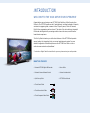
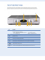
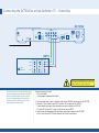
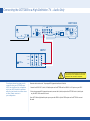
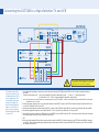
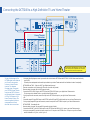
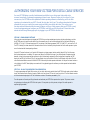
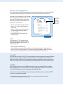
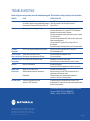
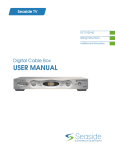
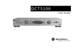
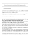
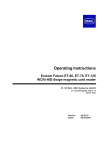
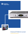
Motorola DCT5100 Set-Up Guide
HIGH-DEFINITION TELEVISION
IMPORTANT SAFETY INSTRUCTIONS
The Motorola DCT5100 has been designed to operate reliably in a well-ventilated household environment. Slots and openings
in the unit cabinet are provided for ventilation. These openings should never be blocked by placing the product on a bed, sofa,
rug, or similar surface. The unit should be positioned with at least 2 inches of space above and on all sides.
V E N T I L AT E
2 inch space
2 inch
space
• Position the DCT5100 with at least 2 inches of space above and on all sides.
• Do not block the slots and openings in the DCT5100.
• Do not place anything on top of the DCT5100.
• Do not position the DCT5100 in an enclosed space that would restrict airflow around the unit.
• Do not position the DCT5100 near any external heat source that could raise the temperature around the unit.
2 inch
space
INTRODUCTION
WELCOME TO THE HIGH-DEFINITION EXPERIENCE
Congratulations on purchasing a new DCT5100 High-Definition Cable Converter from
Motorola. The DCT5100 opens a world of entertainment, including hundreds of channels,
an interactive program guide, commercial-free CD quality music, Video On Demand,
Pay-Per-View programming and much more*. The state of the art technology, integrated
HD decoder and digital audio processing enable a true wide-screen, surround sound
home-theater experience.
This Set-Up Guide introduces you to the basic features of the DCT5100 and provides
several options for integrating it into your current entertainment system. For more
detailed configuration information please see the DCT5100 User Guide or visit us
online at www.motorola.com/broadband.
* For details on Digital Cable Services offered in your area, please contact your cable provider.
WHAT’S IN THE BOX
• Motorola DCT5100 Digital HD Decoder
• Power Cable
• Motorola Universal Remote Control
• Service Activation label
• Quick Set-up Guide
• DCT5100 User Manual
• 6 Foot Coaxial Cable
• 6 Foot Stereo Audio Cable
• 6 Foot Component Video Cable
THE DCT5100 FRONT PANEL
The DCT5100 front panel has 12 keys and an LED display. Use the keys to perform basic functions such as access to the electronic
program guide, navigate menus, and purchase Pay-Per-View events. The table following this drawing describes each key and its use.
There are also inputs for a Universal Serial Bus (USB), audio/video jacks and a Smart Card slot. These inputs are for future applications
under development and are not enabled on this unit.
1
2
Key
1
3 4 5
6 7 8
9
Description
LED
Displays the channel number or time of day.
There are four indicator lights on the LED screen:
• MSGS. — the DCT5100 has received messages for you to read
• A/B — the RF bypass is active
2
10
• ON — the DCT5100 is powered on
• REMOTE — the remote control is in use
CURSOR Moves the cursor around the program guide and menu screens.
3
MENU
Displays the main menu.
4
POWER
Turns the device on or off.
5
INFO
Displays the current channel and program information.
6
A/B
Use to manually enable the RF bypass function. You must have a cable-ready TV for this function to operate. (Optional.)
7
SELECT
Selects menu options, on demand programming, Pay-Per-View events or programs from the program guide.
8
GUIDE
Displays the program guide.
9
CHANNEL +
CHANNEL -
Changes the channels by moving up or down.
10
SMART CARD
SLOT
This interface is intended to support electronic commerce activity utilizing a Smart Card. (Not enabled on this unit.)
NOTE: The rear panel of your DCT5100 may vary from this drawing because
of the different configurations that are available. Please contact your service
provider to determine which connections are supported on your system.
THE DCT5100 BACK PANEL
The rear panel of the DCT5100 consists of three types of interfaces — audio, video and data. The table following this drawing describes
each connection and its use.
1
2
8
3
4
9
10
5
6
11
7
12 13 14
15
KEY
DESCRIPTION
1
TO TV/VCR
This coaxial output connector is used to connect the DCT5100 to a TV or VCR operating on channel 3 or 4.
2
CABLE IN
The CABLE IN connector receives the incoming signal from your cable service provider.
3
ETHERNET
The Ethernet port that supports PC networking. (Not currently enabled.)
4
AUDIO IN R
AUDIO IN L
These connectors are used to connect a set-top between a peripheral audio device such as a CD player and a stereo
tuner or A/V receiver. In the current DCT5100 release, the audio from the peripheral device will pass through the DCT5100 when
it is turned off.
5
SPDIF
The orange coaxial SPDIF connector is a digital output connection that carries Dolby Digital 5.1 audio or PCM audio.
It is used to connect the DCT5100 to a stereo tuner or A/V receiver to provide surround-sound, theater-style audio.
6
VIDEO IN
VIDEO OUT
The VIDEO IN connector accepts a baseband video input from a VCR, camcorder or other video device. (Not currently enabled.)
The VIDEO OUT connector is used to deliver baseband video to an external device such as a VCR or TV.
7
OUTLET
This AC outlet may be used to plug your TV into the DCT5100 as a convenient additional outlet.
8
IR
This connector enables the DCT5100 to control a VCR while recording a selected program. Not all electronic program guides
support this feature.
9
USB
The Universal Serial Bus (USB) is used to support devices such as keyboards, joysticks, scanners, disk storage, PCs,
printers, and digital cameras. (Not currently enabled.)
10
AUDIO OUT R
AUDIO OUT L
The RCA phono-type connectors are used to deliver audio to a stereo receiver.
11
Y Pb Pr
These connectors are used to deliver component video to an HD-ready TV or monitor. Though capable of delivering
standard definition video to your TV or monitor, these cables are necessary to deliver High Definition video.
12
TV PASS CARD
For Future Use
13
S-VIDEO
This connector is used to deliver high quality, standard definition video to external devices that accept S-Video inputs, such as a
high-end VCR or TV.
14
OPTICAL
SPDIF
The OPTICAL SPDIF connector is an optical digital output connection that carries Dolby Digital 5.1 audio or PCM audio.
It is used to connect the DCT5100 to a stereo tuner or A/V receiver to provide surround-sound, theater style audio.
15
POWER INLET
For the female end of the supplied power cord.
Connecting the DCT5100 to a High-Definition TV – Video Only
DCT5100
VIDEO
AUDIO IN
R
SPDIF
IN
OUT
HPNA
IR
TO
TV/VCR
L
S-VIDEO
R
CABLE
IN
L
Y
Pb
Pr
TV
Pass Card
AUDIO
OUT
USB
OPTICAL
SPDIF
IEEE 1394
SWITCHED
105/125V
60Hz
4A MAX
500W MAX
CONVENIENCE
OUTLET
HDTV
Video 1
Video 2
S-Video
Video 3
Y
Pb
Video
Cable/
Antenna IN
Audio
Pr
R
L
R
L
R
L
Do not plug the DCT5100 power cord into a wall
outlet until you have completed all connections
between the DCT and other components.
This diagram shows the High-Definition video
connection between your Motorola DCT5100
and your High-Definition television (HDTV).
This is the primary diagram for providing
HD video and should be done prior to the
following audio configurations.
Connector cables to be used:
• 6 ft coaxial cable
• Three-pronged component video cable
1. Using a coaxial cable, connect cable wall outlet to the CABLE IN coaxial input on the DCT5100.
2. Locate the Y Pb Pr inputs on your HDTV and the Y Pb Pr outputs on the DCT5100.
To make identification easy, these connecters are color-coded on the DCT5100
(Y = green, Pb = blue, and Pr = red). Colors may vary on your HDTV.
3. Using a three-jack component video connector, connect the Y output on the DCT5100
to the Y input on your HDTV. Do the same for the Pb and Pr connections.
Connecting the DCT5100 to a High-Definition TV – Audio Only
DCT5100
VIDEO
AUDIO IN
R
SPDIF
IN
OUT
HPNA
IR
TO
TV/VCR
L
R
CABLE
IN
IEEE 1394
S-VIDEO
L
AUDIO
OUT
USB
Y
Pb
Pr
TV
Pass Card
OPTICAL
SPDIF
SWITCHED
105/125V
60Hz
4A MAX
500W MAX
CONVENIENCE
OUTLET
HDTV
Video 1
Video 2
S-Video
Video 3
Y
Pb
Video
Cable/
Antenna IN
Audio
Pr
R
L
R
L
R
L
Do not plug the DCT5100 power cord into a wall
outlet until you have completed all connections
between the DCT and other components.
This diagram shows the primary audio
connection from your DCT5100 to your
HDTV. You should use this configuration
only if your HDTV has built-in speakers
and you do not intend to include a stereo
or Home Theater receiver in
your configuration.
Connector cables to be used: Two-pronged RCA type audio cable (red & white)
1. Locate the AUDIO OUT L (white) & R (red) outputs on the DCT5100 and the AUDIO IN L & R inputs on your HDTV.
2. Using a two-pronged RCA type audio connector, connect the L (white) output on the DCT5100 to the L (white) input
on your HDTV. Do the same for the red.
If your HDTV offers digital audio inputs you may use the SPDIF or Optical SPDIF outputs on the DCT5100 to connect
the audio.
Connecting the DCT5100 to a High-Definition TV and VCR
DCT5100
VIDEO
AUDIO IN
R
SPDIF
IN
OUT
HPNA
IR
TO
TV/VCR
L
R
CABLE
IN
IEEE 1394
S-VIDEO
L
AUDIO
OUT
USB
Y
Pb
Pr
TV
Pass Card
OPTICAL
SPDIF
SWITCHED
105/125V
60Hz
4A MAX
500W MAX
CONVENIENCE
OUTLET
VCR
Cable/
Antenna IN
Cable/
Antenna OUT
Audio IN
Video IN
S-Video IN
R L
Audio OUT
Video OUT
S-Video OUT
R
L
HDTV
Video 1
Video 2
S-Video
Video 3
Y
Pb
Video
Cable/
Antenna IN
This diagram should be
used if you intend to use
a standard stereo VCR in
your configuration. This
configuration will allow
you to watch both HD
and Standard Definition
video on your HDTV as
well as record and play
Standard Definition video
via your VCR.
Audio
Pr
R
L
R
L
R
L
Do not plug the DCT5100 power cord into a wall
outlet until you have completed all connections
between the DCT and other components.
1. Using the Video Only diagram, connect your coaxial cable to the Motorola DCT5100 and the DCT5100 Y Pb Pr HD video connection directly to
your HDTV.
Connector Cables to be used: • 1 set of two-pronged RCA type audio cables (red & white) • 2 sets of “Y” audio splitter cables
• 2 S-video cables – OR – 2 sets of single-pronged RCA type video cables (yellow)
Note: The video cables you use will depend on the inputs/outputs on your VCR and HDTV. S-video is considered the higher standard definition video output
and should be your first choice.
2. Connect the single connector end of a Y audio splitter cable to the AUDIO OUT R (red) on the DCT5100. Insert the other ends into the AUDIO IN R
on your VCR and AUDIO IN R on your HDTV.
3. Use the second splitter cable to connect the AUDIO OUT L (white) on the DCT5100 to the AUDIO IN L connections on both the VCR and the HDTV.
4. Use the two-pronged RCA cable to connect the AUDIO OUT L & R on your VCR to the AUDIO IN L & R on your HDTV.
5. Using an S-video cable, connect the S-VIDEO output on the DCT5100 to the S-VIDEO IN on your VCR. Then use the second S-video cable to connect
the S-VIDEO output on the VCR to the S-VIDEO IN on your HDTV.
– OR –
6. Using your single-pronged RCA type video connector cable, connect the VIDEO OUT (yellow) connector on the DCT5100 to the VIDEO IN connector
on your VCR. Next, use the second single-pronged RCA type video connector cable to connect the VIDEO OUT connector on your VCR to the VIDEO
IN connector on your HDTV.
Connecting the DCT5100 to a High-Definition TV and Home Theater
DCT5100
VIDEO
AUDIO IN
R
SPDIF
IN
OUT
HPNA
IR
TO
TV/VCR
L
S-VIDEO
R
CABLE
IN
L
AUDIO
OUT
USB
Y
Pb
Pr
TV
Pass Card
OPTICAL
SPDIF
IEEE 1394
SWITCHED
105/125V
60Hz
4A MAX
500W MAX
CONVENIENCE
OUTLET
Home Theater
Receiver
IN
OUT
IN
OUT
IN
S-Video
Y
Pb
Pr
Coaxial
#1
Video
Right
R
R
R
Left
L
L
L
Video 1
Monitor
Digital Audio
AV #2
AV #1
Optical SPDIF
#2
HDTV
Video 1
Video 2
S-Video
Video 3
Y
Pb
Video
Cable/
Antenna IN
To take full advantage of the
DCT5100 digital audio features
you’ll want to incorporate
a stereo or Home Theater
receiver. This diagram
illustrates how to integrate
your DCT5100, Home Theater
receiver and HDTV. We have
not illustrated how to integrate
a VCR or DVD player with a
Home Theater receiver. The
manual supplied with these
components would best
describe those connections.
Audio
Pr
R
L
R
L
R
L
Do not plug the DCT5100 power cord into a wall
outlet until you have completed all connections
between the DCT and other components.
1. Using the Video Only diagram, connect your coaxial cable to the Motorola DCT5100 and the DCT5100 Y Pb Pr HD video connection directly
to your HDTV.
The audio options are dependent on the audio inputs available on your Home Theater receiver. We’ve listed them in order of sound quality.
OPTION ONE and TWO – Optical or RCA Type Digital Audio (orange)
(These two connections are of similar quality. Either one or the other may be used.)
Connector cables to be used: Optical or RCA type audio cable
2. Locate the OPTICAL SPDIF output on the DCT5100 and the OPTICAL SPDIF input on your digital Home Theater receiver.
This input may also be labeled Toslink on your digital Home Theater receiver.
3. Using an optical audio connector, connect the output on the DCT5100 to the input on your digital Home Theater receiver.
– OR –
2. Locate the orange RCA type SPDIF output on the DCT5100 and the RCA type SPDIF or digital audio input on your Home Theater receiver.
3. Using a single-pronged RCA type audio connector, connect the output on the DCT5100 to the input on your Home Theater receiver.
OPTION THREE – Baseband Audio
Connector cables to be used: Two-pronged RCA type audio cable (red & white)
3. Locate the AUDIO OUT L (white) & R (red) outputs on the DCT5100 and the AUDIO IN L & R inputs on your Home Theater receiver.
4. Using a two-pronged RCA type audio connector, connect the L & R outputs on the DCT5100 to the L & R inputs on your Home Theater
receiver. Remember L will go to L, and R will go to R.
AUTHORIZING YOUR NEW DCT5100 FOR DIGITAL CABLE SERVICES
Your new DCT5100 brings a world of entertainment possibilities to your living room: high-quality video,
surround-sound audio, on-demand programming and much more. However, before you can enjoy all of your
new services, the DCT5100 must be updated with latest operating software, authorized by your local cable
operator, and customized for your HDTV. Sounds like a big deal, but it’s not. The software download will happen
automatically once you connect the power supply and attach your digital cable feed. This section covers
the steps required to download the necessary software, notify your cable company that your DCT5100 is ready
to receive programming, and configure your DCT5100 to work with your HD television set. Please take a few
minutes to read through these pages prior to plugging-in your DCT5100 for the first time.
STEP ONE – DOWNLOADING SOFTWARE
After using the connection diagrams to integrate the DCT5100 into your home entertainment system, plug the supplied power cord into
the DCT5100 power inlet and your wall outlet. After a few moments you will see the following appear on the front panel LED display:
HUNT(fig. 1), Fr 1 (fig. 2). The search may stop at FR 1 or continue in the following sequence; HUNT, Fr 2, HUNT, Fr 3, and so on thru Fr 10.
The DCT is checking for a data channel with information that will allow it to identify and synchronize itself to the cable operators’ system
as well as download the latest operating software.
Once the DCT locates the channel, you’ll see the LED change to a spinning progress indicator and the letters DL (fig. 3) which means
that the download process in underway. This process may take up to 45 minutes (or longer if your Cable Operator is experiencing high
demand). As long as the progress indicator continues to spin, the download is progressing. After the download is complete, the LED
display will read EF (fig. 4) and then FP (fig. 5), both may display for up to 60 seconds. After this, the LED display will go blank. This indicates that the download was successful and the DCT5100 is now ready for cable operator authorization. You may see a channel number or
a clock display in the LED. These displays are normal and will vary depending upon the software your cable operator has downloaded to
your DCT5100.
STEP TWO – CALLING YOUR OPERATOR FOR AUTHORIZATION
To receive programming and Digital Cable services, call your local cable service provider. Have the DCT5100 serial number and unit address
handy. These numbers can be found on the peel-off label on the front of new DCTs as well as on the unit itself. The Serial Number consists
of twelve characters beginning with GI. The Unit Address consists of 16 numbers proceeded by “UA:”
The cable operator will record your billing information and authorize your DCT5100 to operate on their system. This process consists
of registering and configuring the DCT5100 for their system. This may take up to thirty minutes (or longer if the cable operator is
experiencing high demand).
MSGS.
ON
A/B
MSGS.
REMOTE
ON
A/B
MSGS.
REMOTE
(fig. 1)
MSGS.
ON
A/B
MSGS.
REMOTE
ON
(fig. 4)
ON
(fig. 2)
A/B
REMOTE
(fig. 5)
A/B
REMOTE
(fig. 3)
STEP THREE – OPTIMIZING YOUR HDTV PICTURE
The final step is tailoring your DCT5100 to the capabilities of your HDTV using the On Screen Menu. This allows the DCT5100
to automatically optimize both Standard and High-Definition video, based on your HDTV and personal preferences.
To access the On Screen Menu, power ON your HDTV and power
OFF the DCT5100. Press the MENU button on either your remote
control or the DCT5100 front panel to call up the On Screen
Display.* You may use either the DCT5100 front panel or the
remote control to navigate the display:
• The arrow on the left indicates the position of the cursor.
• Press the and buttons to select the setting you
wish to change.
• Press the button to select an option for that setting.
• To exit the setting and move to another setting, use
the
and
buttons.
• Press the POWER or MENU button to exit the menu
USER SETTINGS
> TV TYPE
YPbPr OUTPUT
4:3 OVERRIDE
16:9
1080I
480i
CLOSED CAPTION
DISABLED
OPTIONS:
AUTO
PEN SIZE
AUTO
FONT STYLE
AUTO
FOREGROUND COLOR
FOREGROUND OPACITY AUTO
AUTO
BACKGROUND COLOR
BACKGROUND OPACITY AUTO
AUTO
SERVICE SELECTION
AUTO
SETTINGS
The settings shown in this
diagram are for illustrative
purposes, and only
represent one possible
configuration. Please refer
to the following sections
for more setting options.
RESTORE DEFAULTS
and save your settings.
SELECT TV TYPE:
TV TYPE
The first user setting is TV TYPE. Your selection tells the
DCT5100 what type of TV you have and how you prefer to
watch widescreen programming. Your choices are 16:9, 4:3
Letterbox, or 4:3 Pan Scan.
• Choose 16:9 if you have a widescreen HDTV.
• Choose 4:3 Letterbox if you have a standard TV and you prefer to watch widescreen programming in its original aspect ratio.
• Choose 4:3 Pan Scan if you have a standard screen TV and you prefer that widescreen programming is cropped to fill your screen.
Think of this last choice as watching a theater-style movie that has been reformatted to fit your standard screen TV.
Y Pb Pr OUTPUT
Next, use the down arrow to select Y Pb Pr OUTPUT. This setting indicates the picture resolution you prefer when watching High-Definition
programming. The choices, listed in order of highest to lowest picture resolution, are 1080i, 720p, 480p, and 480i. Your selection will
depend on which format(s) your HDTV supports. To maximize your high-definition viewing experience, refer to your television set owner's
manual, and use the right arrow button to choose the setting that indicates the highest picture resolution that your television will support.
4:3 OVERRIDE
Finally, use the down button arrow to select 4:3 OVERRIDE. By selecting 480i or 480p you are telling the DCT5100 to send Standard
Definition programming to your TV in its original broadcast format. Select OFF and the DCT5100 will default to the resolution selected
in the Y Pb Pr OUTPUT setting above. To exit and save changes press the POWER or MENU button.
For more details on configuring your DCT5100 output settings, including setting Closed Caption preferences, see the Motorola DCT5100
User Guide or visit www.motorola.com/Broadband.
* If the On Screen Menu does not appear on your HDTV screen, your TV may not support the default, standard definition setting (480i).
Use the DCT5100 front panel LED to view and change your settings.
TROUBLESHOOTING
Before calling your service provider, review this troubleshooting guide. This information can help you quickly solve the problem.
PROBLEM
CAUSE
POSSIBLE SOLUTION
No sound
Accidentally pressed MUTE on the remote control.
Press MUTE on the remote control to restore the volume level.
The receiver is tuned to the wrong entertainment component. Check that the receiver is set to the proper input source.
You are watching TV using your VCR, and your VCR is off.
Turn your VCR on.
No picture
Cable signal may not be reaching your home.
Check to be sure that all cables are connected properly and that your TV
is tuned to cable channel 3 or 4, if using the TO TV-VCR connections.
Hand-tighten the cable connections if necessary.
Check that your component connection cables are not crossed. Y goes to
Y, Pb to Pb and Pr to Pr.
If connected through the baseband RCA video connection, make sure the
cables are connected properly.
If you are watching TV using your VCR, be sure your VCR is on,
or set to bypass.
Ensure that the proper video display format for your TV has been selected.
No Guide or
wrong Guide
The DCT is not correctly connected to the cable system.
Check that your cable is connected to the DCT set-top first.
NOT looped through the VCR.
Picture or sound is
Coaxial cable is disconnected or loose.
noisy on one channel Cable operator is experiencing system difficulties.
Reconnect the cable and hand-tighten if loose.
Call your cable operator.
Sound from only one Cable connections are disconnected or loose.
stereo speaker
Hand-tighten or reconnect the cables properly.
Ensure that wires are not frayed and plugs are not bent or broken.
No power
Power cord is disconnected.
Reconnect the power cord.
Ensure that the DCT5100 is plugged into an outlet that is always live.
Remote control
does not work
Remote isn't set in cable TV mode.
Obstruction between remote and cable terminal.
Press CABLE on the remote control.
Ensure that nothing is on the DCT5100 or blocking a clear line of
sight between it and the remote control.
Change the batteries in your remote control according to the
instructions in the section, “Installing Batteries.”
Dead batteries.
Poor audio quality
Audio levels on external devices not set
relative to DCT5100 volume level.
For best audio quality, use the remote control to set the DCT5100
to approximately 3/4 of maximum volume level and then adjust the audio
levels on the external devices.
If your problem still persists, contact Motorola Technical
Support at 1.866.MOT.BCSI (1.866.668.2271),
Monday – Sunday, 7:00 AM to 11:00 PM EST.
MOTOROLA and the Stylized M Logo are registered in the US
Patent & Trademark Office. All other product or service names
are the property of their respective owners. Features and
functions subject to change without notice. All rights reserved.
Printed in the U.S.A. © Motorola, Inc. 2003.
5546-203-5K