1
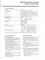
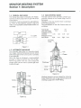
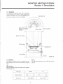
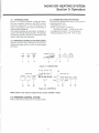
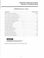
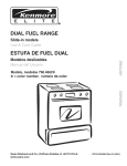
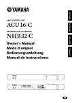
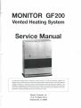
MONITOR GF200
Vented Heating System
Service Manual
GF 200
The information contained herein is proprietary to Monitor Products, Inc. shall not be disclosed, duplicated, nor
otherwise copied in whole or part for any other purpose without express written permission of the Legal Department
of Monitor Products, Inc. This data is issued to authorized Monitor Servicing Personnel for guidance in the
installation and maintenance of the subject product and is intended for use by authorized Monitor service personnel
only. Further, Monitor Products, Inc. reserves the right to make improvements and corrections and to alter
specifications of products described herein, at any time without prior notice.
P. O. BOX 3408
PRINCETON, NEW JERSEY 08543
MONITOR HEATING SYSTEM
Table of Contents
Section 1: Description
1-1 Specifications; 1-2 Special Features; 1-3 Safety Features; 1-4
Munual Gas Valve; 1-5 Automatic Gas Valve; 1-6 Gas Control
Valve; 1-7 Burner; 1-8 Orifice; 1-9 Ignition Plug Unit; 1-10 Ignition
Transformer; 1-11 Flame Detector; 1-12 Combustion Blower;
1-13 Heat Exchanger; 1-14 Flue Pipe; 1-15 Air Circulation Fan;
1-16 Air Pressure Switch; 1-17 Overheat Protector Switch; 1-18
Thermal Fuse; 1-19 Overcurrent Fuse; 1-20 Electrical System;
1-21 Microprocessor; 1-22 Temperature Sensor; 1-23 Safety
Mechanisms; 1-24 Cloth Covered Exhaust Pipe; 1-25 Air
Circulation Fan Guard; 1-26 Slide Selector For The Reset Temp.
Page 1 - 7
Section 2: Installation
2-1 Notice Before Installation; 2-2 Heater Installation; 2-3 Flue
Pipe Clearances; 2-4 Installing An Extension Kit; 2-5 Gas
Connection; 2-6 Gas Conversion Procedure; 2-7 High Altitude
Installation;
Page 9
Section 3: Operation
3-1 Introduction; 3-2 Operating Specifications; 3-3 Operating
Controls And Indicators; 3-4 Operation Control System
Page 11
^
Section 4: Maintenance/Servicing
4-1 Cleaning The Cabinet; 4-2 Checking The Flue Pipe; 4-3
Cleaning The Interior; 4-4 Cleaning The Blower Guard; 4-5
Electric Motor Maintenance; 4-6 Checking The Burner Flame;
4-7 Cleaning The Burner
Pagel 3
Section 5: Troubleshooting
Resistance Values
Component Voltage Readings
Page 15 -16
Section 6: Electrical System
Schematic
Wiring Diagram
Page 17-18
MONITOR HEATING SYSTEM
Section 1: Description
1-1 SPECIFICATIONS
Model No.
Type of Appliance
Input Rating
Output Rating
Electrical Rating
Power Consumption
Heated Air Delivery
Flue Pipe Hole
Dimensions
Weight
Inlet Gas Supply Pressure
Manifold Test Pressure
GF 200
Fan type direct vent wall furnace
High 20,000BTU/hour (Nat.), 20,000 BTU/hour (LP.)
Low 12,60QBTU/hour(Nat.), 13,400 BTU/hour (LP.)
High 16,OOOBTU/hour(Nat.), 16,000 BTU/hour (LP.)
Low 10,200BTU/hour(Nat.), 10,900 BTU/hour (LP.)
120 V, 60 Hz, Less than 2 amperes
65 Watts
High
176 Cubic feet/minute
Low
113 Cubic feet/minute
2.5 inches diameter
Height: 25.6 inches
Width: 20.9 inches
Depth: 12.4 inches
55 pounds
Nat. Gas Max. 10.5 inch W.C. (267 mmH2O)
Min.
5.1 inch W.C. (130
LP. Gas Max. 13.0 inch W C. (330 mmH2O)
Min. 11.0 inch W C. (279 mmH2O)
3.15 inch W. c. (80 mmHzO)
Nat . Gas
LP. Gas
3.19 inch W
(81 mmHaO)
The minimum and maximum inlet gas supply pressures are for the purpose of input adjustment.
1-2 SPECIAL FEATURES
1-3 SAFETY FEATURES
AUTOMATIC IGNITION
MEMORY BACK UP: Set memory can be kept in
case of power failure for up to 5 minutes.
DUAL BLOWERS: Separate fans for combustion
and room air circulation.
THERMOSTATICALLY CONTROLLED: Adjusts to
the desired room temperature.
BUILT-IN TIMER: Heater will automatically
operate as programmed by the user.
AUTOMATIC RESET AFTER POWER FAILURE:
Heater will automatically resume operation
after power is restored.
INDICATOR LIGHTS: Easy-to-see signals show
when heater is in operation, when timer is
activated, and when the burner is operating in
low or high modes.
SAFE RE-LIGHTING: Heater will not restart until
its combustion chamber has cooled.
ELECTRICAL PROTECTION: Heater automatically
shuts off in the unlikely event of a malfunction in
the electrical circuitry or disruption of the power
supply.
NO EXHAUST IN ROOM: Products of combustion
are discharged outdoors.
FLUE PIPE: Outside air is drawn through a pipewithin-a-pipe venting system. This process
preheats combustion air and regains heat from
exhaust gases.
CLEAN OPERATION: Products of combustion are
vented outside.
CONSUMES NO ROOM AIR: Air for combustion
is drawn from outside.
EASY INSTALLATION: Includes all parts required
for standard installation
A CAUTION: ALTERNATE POWER SOURCES
The Monitor GF200 may not operate when
powered by sources such as an auxiliary
generator, UPS (Uninterrupted Power
Source), inverters, etc.
This unit may not operate on a GFI (Ground
Fault Interrupter) power circuit.
Check with your dealer for guidance on
specific applications.
MONITOR HEATING SYSTEM
Section 1: Description
1-4 MANUAL GAS VALVE
The Manual Gas Valve is included with Heater.
Connect the Manual Gas Valve to gas inlet at rear
of the cabinet.
Connection must be checked for gas-tightness
by means of leak detector solution, soap and
water, or an equivalent nonflammable solution, as
applicable.
1-6 GAS CONTROL VALVE
The Gas Control Valve provides constant gas
pressure (volume) of two modes (High, Low) to
the burner.
Operation of the Gas Control Valve is controlled
by the Microprocessor.
The specifications of the Gas Control Valve are
as follows:
Type of gas
Natural
Inlet Gas Supply
7.0
Pressure (in W.C.)
Manifold
3.15
1.34
Pressure (in W.C.)
Burn Mode
High
Low
LP
11.0
3.19 1.42
High
Low
Adjusting
Screw
Figure 1 -1
1-5 AUTOMATIC GAS VALVE
The Automatic Gas Valve is a normally closed
two-stage, electro/mechanical device which
either allows gas to flow to the burner or prevents
it from doing so.
When the valve is energized, a spring-loaded
plunger is lifted to permit the flow of gas.
Removing power from the valve drops the
plunger down into the inlet to prevent gas from
passing through.
Diaphragm
Body
Figure 1 -2
Coil
Manifold pressure can be cheked by removing
brass fitting from end of Gas Control Valve and
inserting a guage with 1/8 NPT fitting.
Spring
Body
Valve
Figure 1 -3
MONITOR HEATING SYSTEM
Section 1: Description
1-7 BURNER
This burner is a Bunsen type with a specially
structured flame port section, which shapes and
positions the flame, so it can be wrapped by the
secondary air flow, and burn completely.
Secondary Air
Flame Port Section
Primary Air and Gas
Mixture
Burner Chamber
Burner Port Assy
Burner Assy
Secondary Air
Mixing Plate
Orifice
1-8 ORIFICE
The orifice is made of brass, inserted into the
gas passage of the mixer, and fixed by the gas
pipe.
NOTE:
For altitude applications over 2,000 feet refer to
page 9.
/!\ WARNING:
Use of incorrect orifice will create a fire hazard
and damage unit.
Gas Type
Shape, Stamp
Orifice size
LP
Natural
(|
t—
Figure 1 -4
1
Dia 2.38mm
1
Q_
-J
Dia 1.87mm
MONITOR HEATING SYSTEM
Section 1: Description
1-9 IGNITION PLUG UNIT
The Electrode is applied high voltage, and
discharges to the Grounding Rod to ignite the
burner. The discharge gap between the Electrode
and the Grounding Rod is 3.5 ± 0.8 mm.
Flame Detector Rod
Electrode
Grounding Rod
Figure 1-6
1-10 IGNITION TRANSFORMER
The Ignition transformer generates high voltage
using 120 VAC power, discharged by the Ignition
plug to ignite the burner.
120VAC
Power
Terminal
High Tension Cord
Grounding Terminal
Figure 1 -7
/!\ WARNING:
Do not touch when functioning. High voltage of
15 kV is generated.
MONITOR HEATING SYSTEM
Section 1: Description
1-11 FLAME DETECTOR
An Electrode which detects that the burner has
been ignited, using the flame as a conductor,
instantaneously detects when the flame
extinguishes and shuts down the Automatic
Valve.
1-12 COMBUSTION BLOWER
The Combustion Blower has a two stage intake
fan. The intake fan draws in outside air thru the
flue pipe for internal combustion.
Burner modes control fan speeds and the
Solenoid Damper in the Blower Casing. Those
functions are as follows:
COMBUSTION AIR CONTROL
Burn Mode
Fan Speed Solenoid Damper
High
High
Off (open)
Low
Low
On (close)
Setting air flow for Solenoid Damper on Low
mode should read 5.5±0.5mmHzO for Nat.
and 5.5±0.5mmH2O for LP.
1-13 HEAT EXCHANGER
An inlet at the top of the Heat Exchanger permits
the heated air to travel from the Combustion
Chamber into the Heat Exchanger.
An outlet, at the bottom of the Heat Exchanger,
permits combustion by-products to be vented to
the Flue Pipe.
While moving through the Heat Exchanger, the
hot air within the Heat Exchanger heats the
outside metal walls. The hot metal walls, in turn,
heat air that is pushed past the Heat Exchanger
and is circulated into the room. An air baffle,
directly in front of the Heat Exchanger, deflects
the heated air downwards, and out, through the
Louver assembly.
1-14 FLUE PIPE
Flue Pipes are available in three (3) sizes. This
provides the flexibility to meet the installation
requirements for dwelling of various wall
thicknesses. One side of the Flue Pipe contains
a "T"-shaped fitting consisting of four ports. This
side is mounted on the interior wall of the
dwelling. The pipe side of the Flue Pipe is vented
outside the dwelling. The Flue Pipe assembly
consists of two concentric tubes. Outside air is
drawn through the cylindrical space between the
tubes.
As the cool air enters, it is heated by the hot air
that is exiting the system.
A large-bore, flexible hose connects the air inlet
port on the Flue Pipe with the Combustion
Blower; a cloth-covered metal pipe connects the
Heat Exchanger with the exhaust outlet on the
Flue Pipe.
1-15 AIR CIRCULATION FAN
The Circulation Fan is driven by a two speed
motor and is designed to circulate the heated
room air. If the heater is running in low burn
mode, the fan also runs at low-speed; in high
burn mode, the fan advances to high-speed.
Operation of the fan is controlled by the
Microprocessor and Fan Thermostat Switch.
Physically assembled with a protective wire
cage, the entire fan assembly is secured to a
bracket on the rear of the Heater Cabinet. A
sheet metal conduit, at the rear of the Heater,
protects the fan wiring from damage.
MONITOR HEATING SYSTEM
Section 1: Description
1-16 AIR PRESSURE SWITCH
This switch consists of a rubber diaphragm which
senses changes in air pressure (it is connected to
the Combustion Blower and the Combustion
Chamber) and a normally-open, micro switch.
Should an abnormal pressure differential exist,
the switch opens to disable the circuitry that
controls the supply of gas. Since the flow of gas
to the Burner is cut off, the flame extinguishes,
and the burner Status Indicators blink.
This safety mechanism can be triggered by
several conditions:
- Leak, loose, or broken tubing which connects
the Air Pressure Switch with the Combustion
Blower or the Combustion Chamber
- Clogged or blocked Air Line
- Blocked or clogged Flue Pipe
-Intake port of the Combustion Blower is
blocked
- Combustion Blower is inoperable
Electrical operation of the Monitor can be thought
of as having the following eight(8) distinct
phases: plug in; turn on; pre-purge; ignition; precombustion; heating; shutdown and post-purge.
1-21 MICROPROCESSOR
Principally consisting of a 64-pin Integrated
Circuit, the Microprocessor provides safety
timings, controls relays and provides clock and
thermostat functions for the Monitor heater.
1-22 TEMPERATURE SENSOR
The sensor which is capable of sensing room
temperature within a range of 42°F to 96°F, can
be left mounted on the back of the heater cabinet
or be wall mounted.
Approximately 61/2' (about 200 cm) of No. 20
AWG Wire is supplied with the sensor to facilitate
wall mounting the sensor in a favorable location.
1-17 OVERHEAT PROTECTOR SWITCH
The normally-closed Overheat Protector Switch
safeguards the heaters against damage due to
overheating.
The Switch is rated 110°C (230° F). Should a
Monitor overheat (internal temperatures rise
beyond 110°C/230°F) the switch will open to shut
down the heater. After extinguishing the flame, the
Burner Status indicators continue to blink. The
Overheat Protector Switch will automatically reset
after cooling down. Once the heater has cooled to
90°C(194°F), the system can be restarted. To
restart the Monitor, proceed as follows:
A. Press ON/OFF Switch to OFF.
B. Allow heater to cool.
C. Troubleshoot the cause of the overheat.
D. Press ON/OFF switch to ON.
E. Proceed with normal operation.
I-23 SAFETY MECHANISMS
Several safety mechanisms have been built into
the Monitor Heating System. These devices
protect the user against personal injury, protect
the heater against damage, and shutdown the
heater if a malfunction occurs.
1-18 THERMAL FUSE
Should the Overheat Protector Switch malfunction,
and the heater be further overheated, the thermal
fuse(internal temperatures rise beyond 167
3
C/333°F) melts and prevent further overheating.
1-25 AIR CIRCULATION FAN GUARD
This guard is an integral part of the fan assembly.
The guard protects the user against physical
injury which could occur from accidental contact
with revolving metal fan blade.
1-19 OVERCURRENT FUSE
2-amp., 125VAC, fuse protects the heater from
damage resulting from power overloads. In the
event of a power surge or internal wiring hazards,
the fuse opens and power to the heater is cut off.
1 -26 SLIDE SELECTOR FOR THE RESET TEMP.
Once power is restored after power interruption
by power failure or by disconnecting heater plug
from wall outlet, heater will resume operation in
the MANUAL mode and maintain room
temperature according to the setting temperature
selected by using the selector for the reset
temperature at the lower right hand side of the
cabinet.
1-20 ELECTRICAL SYSTEM
Electrical power is supplied to the Monitor to run
the Microprocessor and the other electricallyenergized component.
1-24 CLOTH COVERED EXHAUST PIPE
Insulating cloth covers are to be placed over all
metal surfaces of the Exhaust Line during
installation. Since combustion by-products are
vented at elevated temperatures, the Exhaust
Pipe will become hot during operation. The
insulating cloth covers protect the user from burn
hazards associated with accidental contact with
these heated metal surfaces. During installation
make sure that all Exhaust Lines are tight. Do not
operate the heater without the insulating covers.
MONITOR HEATING SYSTEM
Section 1: Description
LU
CO
in
z
o
CO
ID
CQ
5
O
o
LU
o
CO
LU
LU
cp
1
O)
^
MONITOR HEATING SYSTEM
Section 2: Installation
2-1 NOTICE BEFORE INSTALLATION
After check, reinstall fitting and check for leaks.
Refer to the service manual of the Monitor GF500
2-7 HIGH ALTITUDE INSTALLATION
Refer to the service manual of the Monitor GF500
All Units must be installed according to the
following chart to determine which orifice will be
used for the appropriate altitude.
NOTE.-Use the cardboard template provided with
the Heater for flue pipe location.
Just in case the template was misplaced, the
approximate flue pipe hole location measurements
are follows:
NATURAL GAS
UP TO 2000 feet No changing orifice(2.38mm)
2000-6000 feet 2.28 mm drill size orifice
2-2 HEATER INSTALLATION
The center of the Joint Pipe
opening, which connects
to the Flue Pipe.
Back of Healer
LP GAS
UP TO 2000 feet No changing orifice(1.87mm)
2000-6000 feet 1.78 mm drill size orifice
</I\ WARNING:
Do not use above 6000 feet.
Fuel Inlet
2-3 FLUE PIPE CLEARANCES
Refer to the service manual of the Monitor GF500
2-4 INSTALLING AN EXTENSION KIT
Refer to the service manual of the Monitor GF500
2-5 GAS CONNECTION
Refer to the service manual of the Monitor GF500
2-6 GAS CONVERSION PROCEDURE
1. Replace the natural orifice with the LP orifice
which is included in the conversion kit.
Check orifice fitting for gas leak
•Slide the gas type selector on PCB to the LP
position.
•Check that the manifold pressure matches the
following values. If not adjust them -to the
following values using volume resister(VR1:Hi
VR2:Lo)on the PCB.
Hi:3.19"-S 2 5 W.C.
Lo:1.42"-g- 16 W.C.
MONITOR HEATING SYSTEM
Section 3: Operation
3-1
3-2 OPERATING SPECIFICATIONS
INTRODUCTION
Monitor is an easy-to-operate vented gas heater.
Routine operation features high BTU output,
automatic adjustment of room temperature, low
power consumption, and choice of automatic or
manual heater operation.
This section provides all information necessary to
operate the Monitor Heating System. All operation
procedures specified should be performed in the
order in which they are described.
The following specifications apply to the operation
of the Monitor GF 200.
- Rated Efficiency: 81 %
- Power Consumption: as follows
High Bum 65 watts, Low Burn 65 watts
- Circulation Fan Output: 176 cubic feet/min
- Potential Heating Area: 600 - 1200 sq. feet
3-3 OPERATING CONTROLS AND INDICATORS
Several controls and indicators are used to
operate the heater and to monitor its performance
as follows:
RUN
AUTO
EC
°LN°SMY
BURNER STATUS
Figure 3-1, INDICATORS
11 12 13 14 15
OPERATION
ON/OFF
21
AUTO
22
ECONOMY
PLUS
iTIMfeR
| TIN
SELECTOR
CLOCK
|
,
S T
st
2 nd 3Vd 4th
16
TIME/TEMP SET
TIME |
'
I
10
23
| HOUR MINUTE SET CLEAR
17
Figure 3-2, CONTROLS
NOTE: Refer to the service manual of the monitor GF500 in detail
3-4 OPERATION CONTROL SYSTEM
Refer to the service manual of the monitor GF500
11
18
19
20
MONITOR HEATING SYSTEM
Section 4: Maintenance / Servicing
4-1 CLEANING THE CABINET
Refer to the service manual of the Monitor GF500
4-2 CHECKING THE FLUE PIPE
Refer to the service manual of the Monitor GF500
4-3 CLEANING THE INTERIOR
Refer to the service manual of the Monitor GF500
4-4 CLEANING THE BLOWER GUARD
Refer to the service manual of the Monitor GF500
4-5 ELECTRIC MOTOR MAINTENANCE
Refer to the service manual of the Monitor GF500
4-6 CHECKING THE BURNER FLAME
Refer to the service manual of the Monitor GF500
4-7 CLEANING THE BURNER
Refer to the service manual of the Monitor GF500
13
MONITOR HEATING SYSTEM
Section 5: Troubleshooting
GF200 Resistance Values
APPROX. OHMS
COMPONENT
Ignition Transformer (connector E/E)
108,000
Power Transformer (1)-Primary (AC 120V)
66
Power Transformer (l)-Secondary (AC 11V)
1.6
Power Transformer (l)-Secondary (AC 120V)
647
Power Transformer (2)-Primary (AC 120V)
66
Power Transformer (2)-Secondary (AC 22V)
6.4
Damper Solenoid (connector I/I)
4,600
Resistor (connector G/G)
68
Circulation Fan (R & BK)
235
Circulation Fan (BK & Y)
247.5
Combustion Blower (BK & BK)
18
Thermistor (connector Q/Q at 77°F)
10,000
Fuse 2A (read with fuse out)
0.1
Gas Control Valve (connector P/P)
87
Gas Solenoid Valve (connector UL)
2,400
Gas Solenoid Valve (connector M/M)
2,400
WARNING:
DISCONNECT HEATER FROM POWER SOURCE
BEFORE MAKING ANY RESISTANCE TESTS.
NOTE: Refer to the service manual of the monitor GF500 in detail.
15
MONITOR HEATING SYSTEM
Section 5: Troubleshooting
GF 200 Component Voltage Readings
COMPONENT
READING TAKEN AT
Thermistor
Q on PCB Sensor Disconnected
Thermistor
AC
DC
5
All readings taken with components connected to PCB.
Q on PCB Sensor connected
1.5 - 3.2
Air Pressure Switch/
Overheat Protector Closed
J on PCB
0
Air Pressure Switch/
Overheat Protector Open
J on PCB
110
Damper Solenoid
I on PCB
105
Gas Control Valve High mode
P on PCB
8.7
Gas Control Valve Low mode
P on PCB
6.2
Circulation Fan High Speed
R to BK
110
Circulation Fan Low Speed
R to BK
93
Ignition Transformer
E on PCB
110
Power Transformer (1)
(primary side)
AC 120V
110
Power Transformer (1)
(secondary side)
AC 11V
AC 120V
11
120
Power Transformer (2)
(primary side)
AC 120V
110
Power Transformer (2)
(secondary side)
AC 22V
Combustion Blower High Speed
F on PCB
Combustion Blower Low Speed
F on PCB (Q1 is off)
88
Resistor
G on PCB
22
Gas Solenoid Valve
L on PCB
105
Gas Solenoid Valve
M on PCB
105
22
110
16
'
MONITOR HEATING SYSTEM
Secction 6: Electrical System
17
1. Unless otherwise specified, unit of capacitor
should be yuF and unit of resistor should be Q.
2. Unless otherwise specified, diode should be
cat. NO. 1S2076A and resistor should be J
type 1/4W or 1/8W.
MONITOR HEATING SYSTEM
Section 6: Electrical System
WIRING DIAGRAM
CAUTION:
• Label all wires prior to disconnection when
servicing controls. Wiring errors can cause
improper and dangerous operation.
Verify proper operation after servicing.
• If any of the original wire as supplied with the
appliance must be replaced, it must be
replaced with a wire of at least a 105°C
temperature rating.
GAS CONTROL
VALVE
CODE
Bk
Bl
Br
G
Or
R
W
Y
Gr
RESET TEMP
SELECTOR
TF
COLOR
Black
Blue
Brown
Gray
Orange
Red
White
Yellow
Green
OHT
BLOCK DIAGRAM
RESET TEMP
SELECTOR
MARK
BM
ER
F
FM
FR
FT
OHT
PS
RC1-4
R1~4
SL
SP
SV1
SV2
TA1-4
TF
TH
TR1
TR2
PARTS NAME
COMBUSTION BLOWER MOTOR
ELECTRODE
CURRENT FUSE
CIRCULATION FAN MOTOR
FLAME ROD
FAN THERMOSTAT
OVERHEAT THERMOSTAT
AIR PRESSURE SWITCH
RECTIFICATION CIRCUIT
RELAY
SOLENOID
SPARKER
SOLENOID VALVE 1
SOLENOID VALVE 2
TRIAC
THERMAL FUSE
THERMISTOR
TRANSFORMER 1
TRANSFORMER 2
•3C- Grounded inside chassis at bottom of unit.
GAS CONTROL
VALVE
18
MONITOR HEATING SYSTEM
Parts List
NO.
PARTS NAME
REMARKS NO.
PARTS NO
QTY
1
ADJUSTABLE LEG
5019
4
33
PARTS NAME
PRESSURE DETECTIVE PIPE
PARTS NO. QTY
6820
1
2
TRAY
6800
1
34
BURNER ASSY
6821
1
3
AIR SUPPLY HOSE A
6101
1
35
MIXING PLATE ASSY
6822
1
4
AIR SUPPLY HOSE B
6102
1
36
BURNER PORT ASSY
6823
1
5
ORING(PIO)
6604
1
37
FLAME HOLDER
6824
1
6
AUTOMATIC GAS VALVE UNIT
6801
1
38
BURNER PACKING
6825
1
7
GAS PIPE ASSY
6802
1
39
ORIFICE HOLDER
6826
1
8
GAS INLET JOINT
6803
1
40
ORIFICE GUIDE
6643
1
1
9
ORING(P11)
6609
1
41
GASKET 7
6827
10
GAS PIPE JOINT
6804
1
42
BLOWER ASSY
6828
1
11
0 RING (P14)
6805
1
43
BLOWER MOTOR
6829
1
12
MANUAL GAS VALVE
6601
1
44
SOLENOID
6142
1
13
GASKET 1
6806
1
45
SUCTION CASE A
6143
1
14
BURNER CHAMBER ASSY
6807
1
46
SEAL PACKING
6144
1
15
WINDOW PACKING
6616
1
47
PWB SPACER CLIP A
6461
2
16
MICA PLATE
6617
1
48
PWB SPACER CLIP B
6462
14
17
MICA HOLDER
6618
1
49
PWB ASSY
6830
1
18
PLUG BASE ASSY
6808
1
50
CABINET ASSY
6831
1
FLAME DETECTIVE PLUG ASSY
6809
1
51
RUBBER BUSH
6136
2
18-1
18-2
IGNITION ELECTRODE ASSY
6810
1
52
CORD BUSHING
6833
1
18-3
PLUG HOLDER
6622
1
53
POWER SUPPLY CORD
6648
1
18-4
PLUG PACKING
6623
1
54
CARRYING HANDLE
6138
2
19
GASKET 5
6811
1
55
SENSOR ASSY
6186
1
20
GASKET 6
6812
1
56
SLIDE SWITCH ASSY
6649
1
21
COMBUSTION CHAMBER ASSY
6813
1
57
SLIDE SWITCH PANEL
6207
1
22
ORIFICE (NAT GAS)
6814
1
58
KNOB
6208
1
23
ORIFICE (LP GAS)
6815
1
59
WIRING GUARD
6263
1
24
GASKET 4
6120
1
60
FAN BLADE
6180
1
25
HEAT EXCHANGER ASSY
6816
1
61
CIRCULATION MOTOR
6262
1
26
GASKET 6
6122
1
62
BLOWER GUARD ASSY
6261
1 .
27
EXHAUST DUCT ASSY
6630
1
63
UNDER COVER
6832
1
28
0 RING (P39)
6176
1
64
LOUVER ASSY
6210
1
29
GASKET 2
6817
1
65
FRONT COVER
6833
1
30
AIR PRESSURE SWITCH
6818
1
66
LAMP PANEL
6834
1
31
AIR LINE
6819
1
67
SWITCH & LAMP ASSY
6835
1
32
SPARKER
6634
1
68
FAN THERMOSTAT
6152
1
REMARKS
NOTE : TO OBTAIN PARTS, CONTACT YOUR DEALER OR,
MONITOR PRODUCTS, INC. P.O. BOX 3408, PRINCETON, NEW JERSEY 08543
19
MONITOR HEATING SYSTEM
Parts List
NO
PARTS NAME
PARTS NO. QTY
OVERHEAT THERMOSTAT
6463
1
70
THERMAL FUSE
6836
1
71
TOP COVER
6837
1
72
WALL CLAMP
6194
2
69
73
VENT CONNECTOR
4004
1
74
PIPE HOLDER
4006
1
75
AIR SUPPLY HOSE ASSY
6145
1
76
FLUE PIPE ASSY
6841
1
77
SCREW CAP ASSY
6148
1
78
OUTSIDE FLANGE
6148
1
79
OUTSIDE PACKING
6148
1
80
EXHAUST OUTLET CAP
4014
1
81
AIR PORTO RING
4016
1
82
AIR OUTLET CAP
4805
1
83
HOSE BAND
4008
2
84
AIR DAMPER
6839
1
85
OWNER'S GUIDE
6840
1
86
ORIFICE(2~6000FT LP)
6844
1
87
ORIFICE( 2 -600OFT NAT)
6843
1
88
TRANSFORMER-2
6663
1
89
AIR LINE B
6845
1
90
POWER TRANSFORMER
6251
1
REMARKS NO.
PARTS NAME
PARTS NO.
QTY
REMARKS
NOTE : TO OBTAIN PARTS, CONTACT YOUR DEALER OR.
MONITOR PRODUCTS, INC. P.O. BOX 3408, PRINCETON, NEW JERSEY 08543
20
MONITOR HEATING SYSTEM
Exploded Views and Parts List
^
21
MONITOR HEATING SYSTEM
Exploded Views and Parts List
22