1
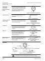
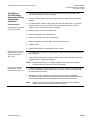
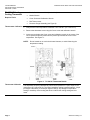
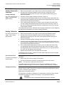
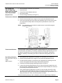
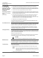
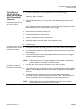
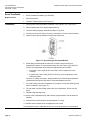
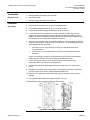
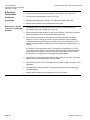
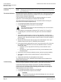
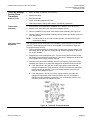
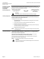
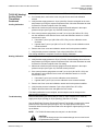
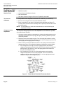
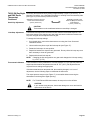
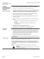
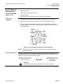
Technical Bulletin
Document No. 155-253P25
TB 239
December 9, 2003
Powers™ Controls
Calibration Kit for Room and Duct
Thermostats
Product Number
832-177
Caution Notation
CAUTION:
Description
This kit contains the equipment required to test pneumatic room and duct thermostats
and pneumatic devices such as valve or damper actuators or positioning relays.
Table 1 lists the items contained in the calibration kit.
Equipment damage or loss of data may occur if you do not
follow procedures as specified.
Table 1. Calibration Kit Parts List.
Item
Description
Quantity
Reference
1
Dial thermometer
1
Figure 1
2
Baumanometer
1
Figure 2
3
Dual scale pressure gauge 0 to 30 psi and 0 to 200 kPa
1
Figure 3
4
1/16-inch (1.6 mm) hex Allen wrench
1
Figure 4
5
1/4-inch (6.4 mm) OD plastic tubing, 2-3/4-inch (70 mm) long
2
Figure 5
6
1/4-inch (6.4 mm) OD plastic tubing plug
2
Figure 6
7
1/4-inch (6.4 mm) OD by 1/4-inch (6.4 mm) OD plastic by
1/8-inch (3.2 mm) NPT brass tee
1
Figure 7
8
3/16-inch (4.8 mm) ID rubber tubing, 12 inches (305 mm) long
2
Figure 8
9
Calibration Tool Kit (Part Number 832-178)
1
TB 240
Dial Thermometer
The dial thermometer is used to determine
the ambient temperature at the thermostat
sensing element.
Figure 1. Dial Thermometer.
Baumanometer
The baumanometer is a squeeze bulb with
a restrictor type shut-off valve. It is used if
a source of air pressure is not available or
if a gradual air pressure change is required
to operate a pneumatic device such as a
valve or damper actuator.
Figure 2. Baumanometer.
Item Number TB 239, Rev. 020
Siemens Industry, Inc.
Technical Bulletin
Document Number 155-253P25
December 9, 2003
Description,
Continued
Dual Scale Pressure
Gauge
Calibration Kit for Room and Duct Thermostats
The dual scale pressure gauge has a dual
scale of 0 to 30 psi and 0 to 200 kPa, and
is bottom-connected. It is used to measure
the air pressure being delivered to a
pneumatic device or the branch line
pressure of a thermostat.
Figure 3. Dual Scale Pressure Gauge.
Hex Allen Wrench
The 1/16 inch hex Allen wrench is used to
loosen the cover screws on room
thermostats.
Figure 4. Hex Allen Wrench.
1/4-Inch (6.4 mm) OD
Plastic Tubing.
The 1/4-inch (6.4 mm) OD plastic tubing is
used to make connections between rubber
tubing and barbed fittings.
Figure 5. 1/4-Inch (6.4 mm) OD Plastic
Tubing.
Tubing Plug
Brass Tee
The tubing plug is used to plug pressurized
1/4-inch (6.4 mm) OD plastic tubing air
lines that have been disconnected during
calibration.
Figure 6. Tubing Plug.
The brass tee holds the pressure gauge
and connects the baumanometer
(Figure 2) to the controlled pneumatic
device, or connects the gauge to the
thermostat’s test port.
Figure 7. Brass Tee.
3/16-inch (4.8 mm) ID
Rubber Tubing
The 3/16-inch (4.8 mm) ID rubber tubing is
used to connect the baumanometer
(Figure 2) or thermostat test port to the tee
holding the gauge.
Figure 8. 3/16-Inch (4.8 mm) ID
Rubber Tubing.
Assembly
Figure 9. Pressure Gauge Assembly.
CAUTION:
Thermostats must be recalibrated whenever sensitivity is changed.
Page 2
Siemens Industry, Inc.
Calibration Kit for Room and Duct Thermostats
Calibration
Instructions
TH-180D and
TH-180R Single
Temperature Room
Thermostats
Required Tools
Thermometer Calibration
Technical Bulletin
Document Number 155-253P25
December 9, 2003
Table of Contents
TH-180D and TH-180R Single Temperature Room Thermostats............................... 3
TH-182 HC Heating- Cooling Thermostat ................................................................... 6
TH-182DN and TH-182 DNV Day-Night and Day-Night Vent Thermostats ................ 9
Direct Acting D Room Thermostat ............................................................................ 12
D Day-Night Thermostats .......................................................................................... 13
TH-192 S Single Temperature Room Thermostat .................................................... 15
TH192 HC Heating/ Cooling Room Thermostat ........................................................ 17
TH192 DN Day/Night and DNV Room Thermostat ................................................... 20
Free Energy Band™ TH193 HC Heating/Cooling Room Thermostat ....................... 23
Free Energy Band™ TH193 HC Hesitation Room Thermostat, ................................ 27
•
Small, flat-blade screwdriver (not included)
•
Nozzle Wrench
•
Cover Screw and Calibration Wrench
•
Dial Thermometer
•
Pressure Gauge Assembly (see Figure 9)
1. Verify that the room temperature is between 70°F and 80°F (21°C and 27°C).
2. Remove cover using the Cover screw and calibration wrench.
3. Invert the cover to expose the bi-metal coil.
4. Place a small, flat-blade screwdriver in the slot located in the center of the bimetal coil, and carefully rotate until the pointer tip indicates the correct room
temperature.
NOTE:
Do not breathe on or touch the bi-metal coil, to avoid influencing the
temperature reading.
Figure 10. Typical Thermostat Details.
Siemens Industry, Inc.
Page 3
Technical Bulletin
Document Number 155-253P25
December 9, 2003
Calibration Kit for Room and Duct Thermostats
TH-180D and
TH-180R Single
Temperature Room
Thermostats,
Continued
The thermostat is factory-calibrated to pass a control pressure of 7 to 8 psi at 72.5°F
(48.2 to 55.1 kPa at 22.5°C). The factory sensitivity setting is approximately 2.5 psi per
degree Fahrenheit (31.0 kPa per degree Celsius). The supply air pressure to the
thermostat should be 18 to 25 psi, 30 psi maximum (124.0 kPa to 172.2 kPa, 206.7 kPa
maximum).
Thermostat Calibration
2. Remove the thermostat cover using the Cover screw and calibration wrench.
1. Verify that the room temperature is between 70°F and 80°F (21°C and 27°C).
3. Set the thermostat to the room temperature shown on the thermometer by
turning the setpoint adjustment knob (on exposed adjustment thermostats), or
using the Hex Allen wrench to turn the adjustment nut on top of the concealed
adjustment thermostat.
4. Construct Pressure gauge assembly as shown in Figure 9.
5. Loosen the test screw approximately 1/2 turn. Place the pressure gauge hose
over the test port body. Stand away from the thermostat for approximately five
minutes to prevent body heat temperature influence.
6. If the control pressure gauge does not read 7psi to 8 psi (48.2 kPa to 55.1 kPa),
turn the nozzle with the Nozzle wrench until it does. If less than 7 psi to 8 psi,
turn the nozzle counterclockwise. If greater than 7psi to 8 psi, turn the nozzle
clockwise.
7. Replace thermostat cover and secure the two screws.
The thermostat is now in calibration and the setpoint adjustment can be changed to the
desired room temperature.
Changing Sensitivity
NOTE:
To change the sensitivity, carefully move the sensitivity slide to the
approximate desired position. It will be 4 psi/°F (49.6 kPa/°C) at the free end
of the bi-metal element, decreasing to 1 psi/°F (12.4 kPa/’C) at the rigid end.
The sensitivity slide must always be in contact with the center leg of the
element. Recalibrate by rotating the nozzle per Step 5.
Table 2. Troubleshooting Guide.
Problem
Check
Control pressure stays Air supply
at approximately zero Nozzle or flapper
Action
Low supply pressure
Recalibrate or replace thermostat
Dirt on nozzle or flapper
Clean nozzle or replace thermostat
Restrictor
Clogged restrictor
Clean or replace restrictor
Calibration
Out of calibration
Recalibrate
Clogged nozzle
Clean nozzle or replace thermostat
Dirt on either supply or
exhaust valve seat
Alternately close and open nozzle by gently
pushing down the bi-metal
Connections are
interchanged or
connection to port is
incorrect
Reverse tubing connections
Control pressure stays Nozzle
at approximately
Calibration
supply pressure
Excessive air leakage Supply and return
from nozzle
line connection
Page 4
Cause
Siemens Industry, Inc.
Calibration Kit for Room and Duct Thermostats
TH-180D and
TH-180R Single
Temperature Room
Thermostats,
Continued
Troubleshooting
Control pressure remains
at 1/2 psi (3.4 kPa)
Technical Bulletin
Document Number 155-253P25
December 9, 2003
1. Remove the thermostat cover and connect the pressure gauge assembly. See
Thermostat Calibration, Steps 1 through 4.
2. Check the throttling pin to see if it is in place under the center leg of the bi-metal
element.
3. Use the Hex Allen wrench to gently press the center bi-metal and pin. The control
pressure should increase. If not, the restriction plate restriction hole, which is
.0045-inch (0.11 mm) diameter, may be clogged.
4. Remove the two screws and holding cover.
5. Remove the gaskets and restriction plate.
6. Clean the restriction hole with compressed air.
7. Replace the gasket, restriction plate, rubber gasket and cover.
8. Tighten screws.
9. Replace thermostat cover and tighten the two screws.
Control pressure remains
at maximum, 25 psi to
30 psi (172.2 kPa to
206.7 kPa)
1. Use a flat-blade screwdriver to gently push the center leg of the bi-metal away from
the throttling pin.
2. If the control pressure does not drop to approximately 1/2 psi (3.4 kPa), check for a
clogged nozzle or a sticking throttling pin.
NOTE:
Excessive air leakage
from nozzle—control
pressure does not drop
Replacement parts are no longer available for this model. If this problem
persists, replace the unit with a TH192 Thermostat.
1. If this occurs and the control pressure does not drop to 1/2 psi (3.4 kPa) when the
bi-metal is pulled away from the throttling pin, then there is dirt on the throttling pin
or brass exhaust valve seat.
2. This dirt particle can usually be removed by moving the pin with a flat-blade
screwdriver so that it alternately opens and closes the nozzle. This fluttering action
will usually dislodge dirt from the throttling pin or brass exhaust valve seat.
NOTE:
Siemens Industry, Inc.
Replacement parts are no longer available for this model. If this problem
persists, replace the unit with a TH-192 Thermostat.
Page 5
Technical Bulletin
Document Number 155-253P25
December 9, 2003
TH-182 HC HeatingCooling Thermostat
Required Tools
Calibration Kit for Room and Duct Thermostats
•
Small, flat-blade screwdriver (not included)
•
Nozzle Wrench
•
Cover Screw and Calibration Wrench
•
Dial Thermometer
•
Pressure Gauge Assembly (see Figure 9)
Thermometer Calibration 1. Verify that the room temperature is between 70°F and 80°F (21°C and 27°C).
2. Remove the thermostat cover using the Cover screw and calibration wrench.
3. Invert cover and place the Cover screw and calibration wrench in the center of the
coil of spiral and carefully rotate until the pointer tip indicates the correct room
temperature. See Figure 11.
NOTE:
Do not breathe on or touch the bi-metal element, to avoid influencing the
temperature reading.
Figure 11. TH 182 HC Thermostat Details.
Thermostat Calibration
Page 6
The thermostat is factory-calibrated to pass a control pressure of 7 psi to 8 psi at 72°F
(48.2 kPa to 55.1 kPa at 22°C). The factory sensitivity setting is approximately 2-1/4 psi
per degree Fahrenheit (27.9 kPa per degree Celsius). Any change in temperature
setting or sensitivity of the heating side does not affect the cooling setting and vice
versa.
Siemens Industry, Inc.
Calibration Kit for Room and Duct Thermostats
Technical Bulletin
Document Number 155-253P25
December 9, 2003
TH-182 HC Heating- 1. Verify that room temperature is between 70°F to 80°F (21.1°C to 26.7°C).
Cooling Thermostat, 2. Remove the thermostat cover using the Cover screw and calibration wrench.
Continued
3. Use the Cover screw and calibration wrench to set the cooling dial to room
temperature by inserting it into the center of the setpoint dial and turning to the
desired temperature.
Cooling Calibration
Use 18 psi (124.0 kPa) air
supply – Reverse Acting
(right bi-metal)
4.
Construct Pressure gauge assembly as shown in Figure 9.
5.
Loosen the test screw approximately 1/2 turn. Place the pressure gauge hose over
the test port body. Stand away from the thermostat for approximately five minutes to
prevent body heat temperature influence.
6.
If the control pressure gauge does not read 7 psi to 8 psi (48.2 kPa to 55.1 kPa),
turn the cooling nozzle with the Nozzle wrench until it does. If less than 7 psi to 8
psi, turn the cooling nozzle counterclockwise. If greater than 7 psi to 8 psi, turn the
cooling nozzle clockwise.
The cooling element is now in calibration and the setpoint adjustment can be changed to
the desired room temperature. Proceed to Heating Calibration.
Heating Calibration
1.
Verify that the room temperature is between 70°F and 80°F (21°C and 27°C).
Use 25 psi (172.2 kPa) air
supply – Direct Acting
(left bi-metal)
2.
Remove the thermostat cover using the Cover screw and calibration wrench.
3.
Use the Cover screw and calibration wrench to set the heating dial to room
temperature by inserting it into the center of the setpoint dial and turning to the
desired temperature.
4.
Construct the Pressure gauge assembly as shown in Figure 9.
5.
Loosen the test screw approximately 1/2 turn. Place the pressure gauge hose over
the test port body. Stand away from the thermostat for approximately five minutes to
prevent body heat temperature influence.
6. If the control pressure gauge does not read 7 psi to 8 psi (48.2 kPa to 55.1 kPa),
turn the heating nozzle with the Nozzle wrench until it does. If less than 7 to 8 psi,
turn the heating nozzle counterclockwise. If greater than 7 psi to 8 psi (48.2 kPa to
55.1 kPa), turn the heating nozzle clockwise.
7. Replace the thermostat cover and tighten the two screws.
The heating element is now in calibration and the setpoint adjustment can be changed
to the desired room temperature.
Use of Selector Rod
(To switch from heating to
cooling nozzle)
The supply pressure may be changed at any individual thermostat to facilitate
calibration.
1. Apply 25 psi (172.2 kPa) air supply on the system.
2. Use a small, flat-blade screwdriver to push the selector rod until it locks in.
NOTE: You may have to rotate the screw to do this.
The cooling nozzle and bi-metal now control, and may be calibrated. See Cooling
Calibration, Steps 2 through 5. Turn the rod to unlatch it when calibration is complete.
Changing Sensitivity
To change the sensitivity, carefully move the sensitivity slide to the approximate desired
position. It will be 4 psi/°F (49.6 kPa/°C) at the free end of the bi-metal element, down to
1 psi/°F (12.4 kPa/°C) at the rigid end.
Adjust one bi-metal slide at a time.
The sensitivity of the slide must always be in contact with the center leg of the element.
Recalibrate by rotating the nozzle. See Heating or Cooling Calibration Step 4.
CAUTION:
The element must be recalibrated whenever sensitivity is changed.
Siemens Industry, Inc.
Page 7
Technical Bulletin
Document Number 155-253P25
December 9, 2003
TH-182 HC HeatingCooling Thermostat,
Continued
Calibration Kit for Room and Duct Thermostats
There are three types of malfunction that might occur, and these can be corrected as
follows. Before beginning:
•
Ensure that there is 18 psi or 25 psi (124.0 kPa and 172.2 kPa) of clean, dry air
supply.
Troubleshooting
NOTE:
•
Only one bi-metal element with its nozzle and throttling pin will operate at
a given time, and the choice of this operating element will be governed by
the supply pressure.
Use the Pressure gauge assembly (Figure 9) to measure control pressure.
If control pressure remains 1. Use either 18 psi (cooling) or 25 psi (heating) (124.0 lPa or 172.2 kPa) air supply.
at 1/2 psi (3.4 kPa)
2. Remove the thermostat cover and connect the Pressure gauge assembly. See
Thermostat Calibration, Steps 1 through 4.
3. Check the throttling pin to see if it is in place under the center leg of the bi-metal
element.
4. Use the Cover screw and calibration wrench to gently press the center bi-metal and
pin. The control pressure should increase. If not, the restriction plate restriction
hole, which is .0045-inch (0.11 mm) diameter, may be clogged.
5. Remove the two screws and restriction cover.
6. Remove the gaskets and restriction plate.
7. Clean the restriction hole with compressed air.
8. Replace the gasket, restriction plate, rubber gasket and cover.
9. Tighten screws.
10.
If control pressure remains 1.
at maximum 18 or 25 psi
(124.0 or 172.2 kPa)
2.
3.
Replace thermostat cover and tighten the two screws.
Test both the heating and cooling supply pressures, since either nozzle could be
clogged.
Use a flat-blade screwdriver to gently push the center leg of the bi-metal away from
the throttling pin.
If the control pressure does not drop to approximately 1/2 psi, check for a clogged
nozzle or a sticking throttling pin.
NOTE:
If excessive Air Leakage
from Nozzle—Control
Pressure Does Not Drop
Replacement parts are no longer available for these models. If this problem
persists, replace the unit with a TH-192 Thermostat.
1. Use either the 18 (cooling) or 25 (heating) psi (124.0 or 172.2 kPa) air supply.
2. If the control pressure does not drop to 1/2 psi (3.4 kPa) when the bi-metal is pulled
away from the throttling pin, then there is dirt on the throttling pin or brass exhaust
valve seat.
3. This dirt particle can usually be removed by moving the pin with a flat-blade
screwdriver so that it alternately opens and closes the nozzle. This fluttering action
will usually dislodge dirt from the throttling pin or brass exhaust valve seat.
NOTE:
Page 8
Replacement parts are no longer available for these models. If this problem
persists, replace the unit with a TH-192 Thermostat.
Siemens Industry, Inc.
Calibration Kit for Room and Duct Thermostats
TH-182DN and
TH-182 DNV DayNight and Day-Night
Vent Thermostats
Required Tools
Technical Bulletin
Document Number 155-253P25
December 9, 2003
•
Small, flat-blade screwdriver (not included)
•
Nozzle Wrench
•
Cover Screw and Calibration Wrench
•
Dial Thermometer
•
Pressure Gauge Assembly (see Figure 9)
Thermometer Calibration 1. Verify that the room temperature is between 70°F and 80°F (21°C and 27°C).
2. Remove the thermostat cover using the Cover screw and calibration wrench.
3. Invert cover and place the Cover screw and calibration wrench in the center of the
coil of spiral and carefully rotate until the pointer tip indicates the correct room
temperature.
NOTE:
Do not breathe on or touch the bi-metal element, to avoid influencing the
temperature reading.
Figure 12. TH182 DN Thermostat Details.
Thermostat Calibration
The thermostat is factory-calibrated to pass a control pressure of 7 psi to 8 psi at 72°F
(48.2 kPa to 55.1 kPa at 22°C). The factory sensitivity setting is approximately 2-1/4 psi
per degree Fahrenheit (27.9 kPa per degree Celsius). Any change in temperature
setting or sensitivity of the heating side does not affect the cooling setting and vice
versa.
Day Setting Calibration
1. Verify that the room temperature is between 70°F and 80°F (21°C and 27°C).
Use 18 psi (124.1 kPa) air
supply
(right bi-metal)
2. Remove the thermostat cover using the Cover screw and calibration wrench.
3. Use the Hex Allen wrench to set the day room temperature by inserting it into the
center of the setpoint dial and turning to the desired temperature.
4. Construct the Pressure gauge assembly as shown in Figure 9..
5. Loosen the test screw approximately 1/2 turn. Place the pressure gauge hose over
the test port body. Stand away from the thermostat for approximately five minutes to
prevent body heat temperature influence.
8.
If the control pressure gauge does not read 7 psi to 8 psi (48.2 kPa to 55.1 kPa),
turn the day nozzle with the Nozzle wrench until it does. If less than 7 psi to 8 psi
(48.2 kPa to 55.1 kPa), turn the day nozzle counterclockwise. If greater than 7 psi to
8 psi (48.2 kPa to 55.1 kPa), turn the day nozzle clockwise.
The thermostat day setting is now in calibration; proceed to Night Setting Calibration.
Siemens Industry, Inc.
Page 9
Technical Bulletin
Document Number 155-253P25
December 9, 2003
Calibration Kit for Room and Duct Thermostats
TH-182DN and
TH-182 DNV DayNight and Day-Night
Vent Thermostats,
Continued
1. Verify that the room temperature is between 70°F and 80°F (21°C and 27°C).
Night Setting Calibration
4. Loosen the test screw approximately 1/2 turn. Place the pressure gauge hose over
the test port body. Stand away from the thermostat for approximately five minutes to
prevent body heat temperature influence.
Use 25 psi (172.2 kPa) air
supply
(left bi-metal)
2. Use the Cover screw and calibration wrench to set the night room temperature by
inserting it into the center of the setpoint dial and turning to the desired temperature.
3. Construct the Pressure gauge assembly as shown in Figure 9.
5. If the control pressure gauge does not read 7 psi to 8 psi (48.2 to 55.1 kPa), turn
the night nozzle with the Nozzle wrench until it does. If less than 7 psi to 8 psi
(48.2 kPa to 55.1 kPa), turn the night nozzle counterclockwise. If greater than 7 psi
to 8 psi (48.2 kPa to 55.1 kPa), turn the night nozzle clockwise.
6. Replace the cover and tighten the two screws.
The thermostat night setting is now in calibration and the setpoint adjustment can be
changed to the desired room temperature.
Use of Manual Selector
The manual selector permits any individual thermostat to operate at its day setting even
though the system is on night supply pressure (25 psi [172.4 kPa]). To latch (lock in) the
selector, its handle must point down. This position is stamped DAY on the cover.
To operate, push the selector in, toward the thermostat, until it latches. To return to
night setting, rotate the handle until it unlatches and comes out to its normal position.
This position is stamped AUTO on the cover.
Changing Sensitivity
To change the sensitivity, carefully move the sensitivity slide to the approximate desired
position. It will be 4 psi/°F (49.6 kPa/°C) at the free end of the bi-metal element, down to
1 psi/°F (12.4 kPa/°C) at the rigid end.
Adjust one bi-metal slide at a time.
The sensitivity of the slide must always be in contact with the center leg of the element.
Recalibrate by rotating the nozzle. See Heating or Cooling Calibration Step 4.
CAUTION:
The element must be recalibrated whenever sensitivity is changed.
DNV Maintenance
The night vent connection of the TH-182 DNV thermostat must be connected to a dead
end chamber (a damper actuator, for example), or vent port R2 must be plugged. If not
connected or plugged, it will exhaust to the atmosphere, and prevent changeover from
day to night operation. Any leak in the night vent air line can also prevent changeover.
Troubleshooting
There are three types of malfunction that might occur, and these can be corrected as
follows. Before beginning:
•
Ensure that there is 18 psi or 25 psi (124.0 kPa and 172.2 kPa) of clean, dry air
supply.
NOTE:
•
Page 10
Only one bi-metal element with its nozzle and throttling pin will operate at
a given time, and the choice of this operating element will be governed by
the supply pressure.
Use the Pressure gauge assembly (Figure 9) to measure control pressure.
Siemens Industry, Inc.
Calibration Kit for Room and Duct Thermostats
Technical Bulletin
Document Number 155-253P25
December 9, 2003
TH-182DN and
1. Use either 18 psi (day) or 25 psi (night) (124.0 or 172.2 kPa) air supply.
TH-182 DNV DayNight and Day-Night 2. Remove the thermostat cover and connect the pressure gauge. See Thermostat
Calibration, Steps 1 through 4.
Vent Thermostats,
Continued
3. Check the throttling pin to see if it is in place under the center leg of the bi-metal
If control pressure remains
at 1/2 psi (3.4 kPa)
element.
4. Use the Cover screw and calibration wrench to gently press the center bi-metal and
pin. The control pressure should increase. If not, the restriction plate restriction hole,
which is .0045-inch (0.11 mm) diameter, may be clogged.
5. Remove the two screws and holding cover.
6. Remove the gaskets and restriction plate.
7. Clean the restriction hole with compressed air.
8. Replace the gasket, restriction plate, rubber gasket and cover.
9. Tighten screws.
If control pressure remains
1. Test both the day and night supply pressures, since either nozzle could be clogged.
at maximum 18 or 25 psi
(124.0 or 172.2 kPa)
2. Use a flat-blade screwdriver to gently push the center leg of the bi-metal away from
the throttling pin.
3. If the control pressure does not drop to approximately 1/2 psi, check for a clogged
nozzle or a sticking throttling pin.
NOTE:
If excessive Air Leakage
from Nozzle—Control
Pressure Does Not Drop
Replacement parts are no longer available for these models. If this problem
persists, replace the unit with a TH-192 Thermostat.
1. Use either the 18 psi or 25 psi (124.0 kPa or 172.2 kPa) air supply.
4. If the control pressure does not drop to 1/2 psi (3.4 kPa) when the bi-metal is pulled
away from the throttling pin, then there is dirt on the throttling pin or brass exhaust
valve seat.
5. This dirt particle can usually be removed by moving the pin with a flat-blade
screwdriver so that it alternately opens and closes the nozzle. This fluttering action
will usually dislodge dirt from the throttling pin or brass exhaust valve seat.
NOTE:
Siemens Industry, Inc.
Replacement parts are no longer available for this model. If this problem
persists, replace the unit with a TH-192 Thermostat.
Page 11
Technical Bulletin
Document Number 155-253P25
December 9, 2003
Direct Acting D
Room Thermostat
Required Tools
Calibration
Calibration Kit for Room and Duct Thermostats
•
D Adjustment Key
•
Small, flat-blade screwdriver (not included)
•
Dial Thermometer
•
Pressure Gauge Assembly (see Figure 9)
1. Verify that the room temperature is between 70°F and 80°F (21°C and 27°C).
2. Remove thermostat cover using D Adjustment Key.
3. Construct Pressure gauge assembly as shown in Figure 9.
4. Loosen test screw (see Figure 13) using a screwdriver, 1/2 turn counterclockwise.
5. Attach Pressure gauge assembly over the test screw body.
Figure 13. Direct Acting D Thermostat Details.
6. Stand away from thermostat for about five minutes to prevent body heat
temperature influence. If control pressure does not read 7 psi to 8 psi (48 kPa to
55 kPa), turn adjustment screw with the D Adjustment Key as follows:
•
If less than 7 psi to 8 psi (48 kPa to 55 kPa), turn the adjustment screw
clockwise.
•
If greater than 7 psi to 8 psi (48 kPa to 55 kPa), turn the adjustment screw
counterclockwise.
If there is no change in pressure, the thermostat is not functioning and should be
replaced with Part Number 832-040 D Thermostat Replacement unit.
7. If the dial reading and room temperature do not agree, loosen dial retaining screw
with a screwdriver. (See Figure 13.)
8. Tilt and rotate until dial reading agrees with room temperature. Do not turn dial
pinion.
9. Retighten dial retaining screw.
10. Remove the D Adjustment Key and Pressure gauge assembly, and let pressure
stabilize.
11. Verify that the control pressure remains between 7 to 8 psi.
12. Replace the thermostat cover and tighten the two screws.
The thermostat is now in calibration and can be set to the desired room temperature.
Page 12
Siemens Industry, Inc.
Calibration Kit for Room and Duct Thermostats
Technical Bulletin
Document Number 155-253P25
December 9, 2003
D Day-Night
Thermostats
•
D Adjustment Key
•
Small, flat-blade screwdriver (not included)
Required Tools
•
Dial Thermometer
•
Pressure Gauge Assembly (see Figure 9)
Calibration
Day Setting
1. Verify that the room temperature is between 70°F and 80°F (21°C and 27°C).
2. Remove the thermostat cover using the D Adjustment Key.
3. Verify that the supply pressure is 18 psi (124 kPa) pressure.
4. Construct the Pressure gauge assembly as shown in Figure 9.
5. Loosen test screw one complete turn, using a screwdriver. Place the pressure
gauge hose over the test port body. Wait several minutes after installing the test
gauge hose before recalibrating. Stand away from the thermostat for approximately
five minutes to prevent body heat temperature influence.
6. Adjust the day dial (left) to the actual room temperature. The test gauge should then
read 7 psi to 8 psi (48 to 55 kPa). If this is not the case, turn the adjusting post using
the D Adjustment Key, as follows:
•
If less than 7 psi to 8 psi (48 kPa to 55 kPa), turn the adjustment screw
counterclockwise.
•
If greater than 7 psi to 8 psi (48 kPa to 55 kPa), turn the adjustment screw
clockwise.
If there is no change in pressure, the thermostat is not functioning and should be
replace with Part Number 182-041 DN Thermostat Replacement kit.
7. Loosen the day dial retaining screw with a screwdriver and reset the day
temperature dial to the correct room temperature.
8. Tilt and rotate until dial reading agrees with room temperature. Do not turn dial
pinion.
9. Retighten dial retainer screw being careful not to change the setting of adjustment
post. Be careful not to come in contact with thermostatic disc.
10. Remove the D Adjustment Key and Pressure gauge assembly, and let pressure
stabilize.
11. Verify that the control pressure remains between 7 to 8 psi.
The Day Setting is now complete; proceed to Night Setting.
Figure 14. D Day-Night Thermostat Details.
Siemens Industry, Inc.
Page 13
Technical Bulletin
Document Number 155-253P25
December 9, 2003
Calibration Kit for Room and Duct Thermostats
D Day-Night
Thermostats,
Continued
1. Verify that the room temperature is between 70°F and 80°F (21°C and 27°C).
Night Setting
3. Repeat Day Setting Steps 4 through 11 to calibrate the night (right) scale.
2. Verify that the supply pressure is 25 psi (172 kPa).
4. Replace the thermostat cover and tighten the two screws.
Manual Reset - System
1. Set changeover lever to the right until a "click" is felt. The thermostat is now
on 25 psi (172 kPa) Night
controlling at the day dial setting (see Figure 14).
Operation
2. Return thermostat supply pressure to day 18 psi (124 kPa). The manual reset lever
should automatically return to the left hand side of day cycle.
3. If the manual reset lever does not return to the left hand side when the supply
pressure is 18 psi (124 kPa), the tension of spring will have to be increased by
turning the adjustment spring retainer clockwise. About one complete turn of the
adjustment spring retainer clockwise will increase the pressure change about 1 psi
(7 kPa).
For example: If the manual reset lever is returned to the day setting at 17-1/2 psi
(120.6 kPa) system pressure, then the spring tension should be increased so that it
would switch over at about 18-1/4 psi (125.7 kPa). This would be approximately
three-fourths of a complete turn of the adjustment spring retainer.
4. Apply 25 psi (172 kPa) night supply pressure. Move reset lever to right. Thermostat
will now control at day dial setting. Check calibration.
5. Move reset lever back to left. Thermostat will now control at night dial setting. Check
calibration.
6. The thermostat is now in calibration. Test hose should be removed and test plug
screwed in tightly.
7. Replace the thermostat cover and tighten the two cover screws.
Page 14
Siemens Industry, Inc.
Calibration Kit for Room and Duct Thermostats
Technical Bulletin
Document Number 155-253P25
December 9, 2003
TH-192 S Single
Temperature Room
Thermostat
•
Small, flat-blade screwdriver (not included)
•
Needle nose pliers
•
Cover Screw and Calibration Wrench
Required Tools
•
Dial Thermometer
•
Dual Scale Pressure Gauge and Pressure Tap Needle (assembled)
Thermometer Calibration 1. Verify that the room temperature is between 70°F and 80°F (21°C and 27°C).
2. Remove thermostat cover using the Cover screw and calibration wrench.
3. Place a screwdriver in the center of the thermometer assembly (see Figure 15).
Carefully rotate the thermometer assembly until the pointer tip indicates the correct
room temperature.
NOTE:
Do not breathe on or touch the bi-metal element, to avoid influencing the
temperature reading.
Figure 15. TH-192 S Thermostat Details.
Sensitivity Adjustment
The factory thermostat sensitivity setting is approximately 2.5 psi/°F (31 kPa/°C). To
change the sensitivity, use a flat-blade screwdriver to carefully move the sensitivity slide
(see Figure 15) to the desired position as follows:
Graduation closest to the rigid
end of the bi-metal element
4 psi/°F (50 kPa/°C)
Graduation closest to the
minimum (MIN) end of the bimetal element
1 psi/°F (12 kPa/°C)
CAUTION:
Thermostats must be recalibrated whenever sensitivity is changed.
Limit Stop Adjustment
Thermostat limit stops define the minimum and maximum thermostat setpoints. The
limit stops engage in the setpoint cam gear teeth and cause interference between the
setpoint cam gear and the adjustment knob gear.
To change the limit stop settings:
1. If not already done, remove the thermostat cover using the Cover screw and
calibration wrench.
2. Use a needle nose pliers to pull the limit stop tab (see Figure 15).
3. Rotate the limit stop to its new position.
4. Reposition between the setpoint cam gear teeth. Do not pull the limit stop any
more than necessary to clear the gear teeth.
Siemens Industry, Inc.
Page 15
Technical Bulletin
Document Number 155-253P25
December 9, 2003
Calibration Kit for Room and Duct Thermostats
Limit Stop Adjustment,
Continued
5. Repeat with second limit stop tab.
NOTE: Changing the limit stop position one gear tooth changes the limit stop setting
by 1-1/3°F (0.7°C).
Thermostat Calibration
The thermostat is factory calibrated to a control pressure of 7.5 psi (52 kPa) when the
setpoint and the ambient temperature are both at 72°F (22°C). No adjustments are
required if these settings are appropriate.
If the thermostat has been tampered with, the sensitivity changed, or it is out of
adjustment, use the following steps to recalibrate the instrument.
The output pressure test port (see Figure 15) is accessible without removing the
thermostat cover through the eighth opening:
•
•
For one-pipe thermostats, the test port is on the right side.
For two-pipe thermostats, the test port is on the left side.
CAUTION:
If you use the wrong test port, thermostat damage can occur and result in
replacement of the device.
1. Verify that the room temperature is between 70°F and 80°F (21°C and 27°C).
2. If not already done, remove the cover using the Cover screw and calibration
wrench.
3. Verify that the supply pressure is 18 psi to 25 psi (124 kPa to 172 kPa), 30 psi
(207 kPa) maximum. Set the dial to the room temperature by turning the exposed
adjustment knob. Allow the thermostat to stand for about five minutes to adjust to
the new setting.
4. Moisten the needle and insert the test gauge and needle adapter in the output
pressure test port (see Figure 15). Read the control pressure.
5. If the control pressure gauge does not read 7 to 8 psi (48.2 kPa to 55.1 kPa), turn
the calibration screw with the Cover screw and calibration wrench or 1/8-inch
wrench until it does.
• If less than 7 psi to 8 psi (48 kPa to 55 kPa), turn the calibration screw
clockwise.
• If greater than 7 psi to 8 psi (48 kPa to 55 kPa), turn the calibration screw
counterclockwise.
6. Remove the Cover screw and calibration wrench, and let the pressure stabilize.
7. Verify that the control pressure remains between 7 and 8 psi (48.2 kPa to
55.1 kPa).
8. Replace the thermostat cover and tighten the two screws.
The sensing element is now in calibration and the setpoint can be changed to the
desired room temperature.
Troubleshooting
Before troubleshooting the thermostat per Table 2, ensure there is clean dry supply air
at 18 psi to 25 psi (12 kPa4 to 172 kPa) minimum, 30 psi (207 kPa) maximum.
Use the Dual Scale Pressure Gauge and Pressure Tap Needle (assembled) to
measure the control pressure at the output test port (see Figure 15). The output
pressure test port is accessible without removing the thermostat cover through the
eighth opening from the top as follows:
• For one-pipe thermostats, the port is on the right side.
• For two-pipe thermostats, the port is on the left side.
CAUTION:
If you use the wrong test port, thermostat damage can occur and result
in replacement of the device.
Page 16
Siemens Industry, Inc.
Calibration Kit for Room and Duct Thermostats
TH192 HC Heating/
Cooling Room
Thermostat
Required Tools
Thermometer
Calibration
Technical Bulletin
Document Number 155-253P25
December 9, 2003
•
Small, flat-blade screwdriver (not included)
•
Needle nose pliers
•
Dial Thermometer
•
Cover Screw and Calibration Wrench
•
Dual Scale Pressure Gauge and Pressure Tap Needle, assembled
1. Verify that the room temperature is between 70°F and 80°F (21°C and 27°C).
2. Remove cover using the Cover screw and calibration wrench.
3. Place a screwdriver in the center of the thermometer assembly (See Figure 16).
4. Carefully rotate the thermometer assembly until the pointer tip indicates the correct
room temperature.
NOTE:
Changeover Point
Adjustment
Do not breathe on or touch the bi-metal element, to avoid influencing the
temperature reading.
The changeover point is factory set to occur between 19 psi and 22 psi (131 kPa and
152 kPa). The changeover point can be field adjusted to occur between 14 psi and
22 psi (96 kPa and 152 kPa).
1. Connect a pressure gauge or a manometer to measure the supply pressure to the
thermostat. Use 30 psi (207 kPa) supply through a positioning switch so pressure
can be fully variable.
2. Determine the current changeover point. Turn the cooling dial so that the cooling
and heating control pressures are different. Then note the changeover point on the
control gauge as the supply pressure changes.
3. Place the Cover screw and calibration wrench in the opening of the thermometer
assembly (see Figure 16) to adjust the changeover adjustment screw as follows:
a. If the changeover is too high, turn off the supply pressure and rotate the
changeover adjustment screw clockwise. One turn decreases the changeover
point by about 3 psi (20 kPa). Turn on the supply pressure and recheck to
verify the new changeover point.
b. If the changeover is too low, turn off the supply pressure and rotate the
changeover adjustment screw counterclockwise. One turn increases the
changeover point by about 3 psi (20 kPa). Turn on the supply pressure and
recheck to verify the new changeover point.
Figure 16. TH192 HC Thermostat Details.
Siemens Industry, Inc.
Page 17
Technical Bulletin
Document Number 155-253P25
December 9, 2003
TH192 HC Heating/
Cooling Room
Thermostat
Sensitivity Adjustment
Calibration Kit for Room and Duct Thermostats
The factory thermostat sensitivity setting is approximately 2.5 psi/°F (31 kPa/°C). To
change the sensitivity, use a flat-blade screwdriver to carefully move the sensitivity slide
(see Figure 16) to the desired position as follows:
Graduation closest to the rigid
end of the bi-metal element
4 psi/°F (50 kPa/°C)
Graduation closest to the
minimum (MIN) end of the bimetal element
1 psi/°F (12 kPa/°C)
CAUTION:
Thermostats must be recalibrated whenever sensitivity is changed.
Limit Stop Adjustment
Thermostat limit stops define the minimum and maximum thermostat set points. The
limit stops engage in the set point cam gear teeth and cause interference between the
set point cam gear and the adjustment knob gear.
To change the limit stop settings:
1. If not already done, remove the thermostat cover using the Cover screw and
calibration wrench.
2. Use a needle nose pliers to pull the limit stop tab (see Figure 16).
3. Rotate the limit stop to its new position.
4. Reposition between the setpoint cam gear teeth. Do not pull the limit stop any
more than necessary to clear the gear teeth.
5. Repeat with second limit stop tab.
NOTE:
Thermostat Calibration
Changing the limit stop position one gear tooth changes the limit stop setting
by 1-1/3°F (0.7°C).
The thermostat is factory calibrated to a control pressure of 7.5 psi (52 kPa) when the
setpoint and the ambient temperature are both at 72°F (22°C). No adjustments are
required if these settings are appropriate.
If the thermostat has been tampered with, the sensitivity changed, or it is out of
adjustment, use the following steps to recalibrate the instrument.
The output pressure test port (see Figure 16) is accessible without removing the
thermostat cover through the eighth opening:
NOTE:
For TH192 HC thermostats, the test port is on the left side.
CAUTION:
If you use the wrong test port, thermostat damage can occur and result in
replacement of the device.
Page 18
Siemens Industry, Inc.
Calibration Kit for Room and Duct Thermostats
TH192 HC Heating/
Cooling Room
Thermostat,
Continued
Cooling Calibration
Technical Bulletin
Document Number 155-253P25
December 9, 2003
1. Verify that the room temperature is between 70°F and 80°F (21°C and 27°C).
2. If not already done, remove the cover using the Cover screw and calibration
wrench.
3. Verify that the supply pressure is 18 psi (124 kPa). Set the cooling dial to the room
temperature by turning the exposed adjustment knob. Allow the thermostat to stand
for about five minutes to adjust to the new setting.
4. Moisten the needle and insert the test gauge and needle adapter in the output
pressure test port (see Figure 16). Read the control pressure.
5. If the control pressure gauge does not read 7 psi to 8 psi (48.2 kPa to 55.1 kPa),
turn the calibration screw with the Cover screw and calibration wrench or 1/8-inch
wrench until it does.
• If less than 7 psi to 8 psi (48.2 kPa to 55.1 kPa), turn the calibration screw
clockwise.
•
If greater than 7 psi to 8 psi (48.2 k Pa to 55.1 kPa), turn the calibration screw
counterclockwise.
6. Remove the Cover screw and calibration wrench and let the pressure stabilize.
7. Verify that the pressure is between 7 psi to 8 psi (48.2 kPa to 55.1 kPa).
The cooling calibration is complete. Proceed to Heating Calibration.
Heating Calibration
1. Verify that the room temperature is between 70°F and 80°F (21°C and 27°C).
2. Verify that the supply pressure is 25 psi (172 kPa). Set the heating dial to the room
temperature by turning the exposed adjustment knob. Allow the thermostat to stand
for about five minutes to adjust to the new setting.
3. Moisten the needle and insert the test gauge and needle adapter in the output
pressure test port (see Figure 16). Read the control pressure.
4. If the control pressure gauge does not read 7 psi to 8 psi (48.2 to 55.1 kPa), turn
the calibration screw with the Cover screw and calibration wrench or 1/8-inch
wrench until it does.
• If less than 7 psi to 8 psi, turn the calibration screw clockwise.
•
If greater than 7 psi to 8 psi, turn the calibration screw counterclockwise.
5. Remove the Cover screw and calibration wrench and let the pressure stabilize.
6. Verify that the pressure is between 7 psi to 8 psi (48.2 kPa to 55.1 kPa).
7. Replace the thermostat cover and tighten the two screws.
The heating calibration is now complete, and the setpoint can be changed to the
desired room temperature.
Troubleshooting
Before troubleshooting the thermostat per Table 2, make certain there is clean dry
supply air at 18 psi (cooling) or 25 psi (heating) (124 kPa to 172 kPa).
Use the Dual Scale Pressure Gauge and Pressure Tap Needle to measure the control
pressure at the output test port (see Figure 16). The output pressure test port is
accessible without removing the thermostat cover through the eighth opening from the
top as follows:
NOTE:
For TH192 HC thermostats, the test port is on the left side.
CAUTION:
If you use the wrong test port, thermostat damage can occur and result
in replacement of the device.
Siemens Industry, Inc.
Page 19
Technical Bulletin
Document Number 155-253P25
December 9, 2003
TH192 DN
Day/Night and DNV
Room Thermostat
Required Tools
Thermometer
Calibration
Calibration Kit for Room and Duct Thermostats
•
Small, flat-blade screwdriver (not included)
•
Needle nose pliers
•
Cover Screw and Calibration Wrench
•
Dial Thermometer
•
Dual Scale Pressure Gauge and Pressure Tap Needle, assembled
1. Verify that the room temperature is between 70°F and 80°F (21°C and 27°C).
2. Remove cover using the Cover screw and calibration wrench.
3. Place a screwdriver in the center of the thermometer assembly (see Figure 17).
Carefully rotate the thermometer assembly until the pointer tip indicates the correct
room temperature.
NOTE:
Changeover Point
Adjustment
Do not breathe on or touch the bi-metal element, to avoid influencing the
temperature reading.
The changeover point is factory set to occur between 19 psi and 22 psi (131 kPa and
152 kPa). The changeover point can be field adjustable to occur between 14 psi and
22 psi (96 kPa and 152 kPa).
1. Connect a pressure gauge or a manometer to measure the supply pressure to the
thermostat. Use 30 psi (207 kPa) supply through a positioning switch so pressure
can be fully variable.
2. Determine the current changeover point. Turn the cooling dial so that the cooling
and heating control pressures are different. Then note the changeover point on the
control gauge as the supply pressure changes.
3. Place the Cover screw and calibration wrench in the opening of the thermometer
assembly (see Figure 17) to adjust the changeover adjustment screw as follows:
a. If the changeover is too high, turn off the supply pressure and rotate the
changeover adjustment screw clockwise. One turn decreases the changeover
point by about 3 psi (20 kPa). Turn on the supply pressure and recheck to
verify the new changeover point.
b. If the changeover is too low, turn off the supply pressure and rotate the
changeover adjustment screw counterclockwise. One turn increases the
changeover point by about 3 psi (20 kPa). Turn on the supply pressure and
recheck to verify the new changeover point.
Figure 17. TH192 DN and TH192 DNV Thermostat Details.
Page 20
Siemens Industry, Inc.
Calibration Kit for Room and Duct Thermostats
Technical Bulletin
Document Number 155-253P25
December 9, 2003
TH192 DN Day/Night The factory thermostat sensitivity setting is approximately 2.5 psi/°F (31 kPa/°C). To
change the sensitivity, use a flat-blade screwdriver to carefully move the sensitivity slide
and DNV Room
(see
Figure 16) to the desired position as follows:
Thermostat,
Graduation closest to the rigid
Graduation closest to the
Continued
Sensitivity Adjustment
end of the bi-metal element
4 psi/°F (50 kPa/°C)
minimum (MIN) end of the bimetal element
1 psi/°F (12 kPa/°C)
CAUTION:
Thermostats must be recalibrated whenever sensitivity is changed.
Limit Stop Adjustment
Thermostat limit stops define the minimum and maximum thermostat setpoints. The
limit stops engage in the setpoint cam gear teeth and cause interference between the
set point cam gear and the adjustment knob gear.
To change the limit stop settings:
1. If not already done, remove the thermostat cover using the Cover Screw and
Calibration Wrench.
2. Use a needle nose pliers to pull the limit stop tab (see Figure 17).
3. Rotate the limit stop to its new position.
4. Reposition between the setpoint cam gear teeth. Do not pull the limit stop any more
than necessary to clear the gear teeth.
5. Repeat with second limit stop tab.
NOTE:
Thermostat Calibration
Changing the limit stop position one gear tooth changes the limit stop setting
by 1-1/3°F (0.7°C).
The thermostat is factory calibrated to a control pressure of 7.5 psi (52 kPa) when the
setpoint and the ambient temperature are both at 72°F (22°C). No adjustments are
required if these settings are appropriate.
If the thermostat has been tampered with, the sensitivity changed, or it is out of
adjustment, use the following steps to recalibrate the instrument.
The output pressure test port (see Figure 17) is accessible without removing the
thermostat cover through the eighth opening:
NOTE:
For TH192 DN and DNV thermostats, the test port is on the left side.
CAUTION:
If you use the wrong test port, thermostat damage can occur and result in
replacement of the device.
Siemens Industry, Inc.
Page 21
Technical Bulletin
Document Number 155-253P25
December 9, 2003
TH192 DN
Day/Night and DNV
Room Thermostat,
Continued
Day Setting Calibration
Calibration Kit for Room and Duct Thermostats
1. Verify that the room temperature is between 70°F and 80°F (21°C and 27°C).
2. Remove the cover using the Cover screw and calibration wrench.
3. Verify that the supply pressure is 18 psi to 25 psi (124 kPa to 72 kPa). Set the day
(right) dial to the room temperature by turning the exposed adjustment knob. Allow
the thermostat to stand for about five minutes to adjust to the new setting.
4. Moisten the needle and insert the test gauge and needle adapter in the output
pressure test port (see Figure 17). Read the control pressure.
5. If the control pressure does not read 7 psi to 8 psi (48 kPa to 55 kPa), turn the
calibration screw (see
6. Figure 16) using the Cover screw and calibration wrench or a 1/8-inch wrench as
follows:
•
If less than 7 psi to 8 psi (48 kPa to 55 kPa), turn the calibration screw
clockwise.
•
If greater 7 psi to 8 psi (48 kPa to 55 kPa), turn the calibration screw
counterclockwise.
7. Remove the wrench and let the pressure stabilize.
8. Verify that the pressure is between 7 psi to 8 psi (48 kPa to 55 kPa).
The Day calibration is now complete. Proceed to Night Calibration.
Night Setting
Calibration
1. Verify that the room temperature is between 70°F and 80°F (21°C and 27°C).
2. Verify that the supply pressure is 18 psi to 25 psi (124 kPa to 172 kPa). Set the
night (left) dial to the room temperature by turning the exposed adjustment knob.
Allow the thermostat to stand for about five minutes to adjust to the new setting.
3. Repeat Day Setting Cooling Calibration steps 4 through 8.
4. Replace the thermostat cover and tighten the two screws.
The Night calibration is now complete, and the setpoint can be changed to the desired
room temperature.
Troubleshooting
Before troubleshooting the thermostat per Table 2, make certain there is clean dry
supply air at 18 psi (day) or 25 (night) psi (124 or 172 kPa).
Use the Dual Scale Pressure Gauge and Pressure Tap Needle to measure the control
pressure at the output test port (see Figure 17). The output pressure test port is
accessible without removing the thermostat cover through the eighth opening from the
top as follows:
NOTE:
For TH192 DN and DNV thermostats, the test port is on the left side.
CAUTION:
If you use the wrong test port, thermostat damage can occur and result
in replacement of the device.
Page 22
Siemens Industry, Inc.
Calibration Kit for Room and Duct Thermostats
Technical Bulletin
Document Number 155-253P25
December 9, 2003
Free Energy
Band™ TH193 HC
Heating/Cooling
Room Thermostat
•
Small, flat-blade screwdriver (not included)
•
Needle nose pliers
•
Cover Screw and Calibration Wrench
Required Tools
•
Dial Thermometer
•
Dual Scale Pressure Gauge and Pressure Tap Needle, assembled
Thermometer
Calibration
1. Verify that the room temperature is between 70°F and 80°F (21°C and 27°C).
2. Remove the thermostat cover using the Cover screw and calibration wrench.
3. Place a screwdriver in the center of the thermometer assembly (see Figure 18).
Carefully rotate the thermometer assembly until the pointer tip indicates the correct
room temperature.
Figure 18. Free Energy Band TH193 HC Thermostat Details.
NOTE:
Sensitivity Adjustment
Do not breathe on or touch the bi-metal element, to avoid influencing the
temperature reading.
The factory thermostat sensitivity setting is approximately 2.5 psi/°F (31 kPa/°C). To
change the sensitivity, use a flat-blade screwdriver to carefully move the sensitivity slide
(see Figure 18) to the desired position as follows:
Graduation closest to the rigid
end of the bi-metal element
4 psi/°F (50 kPa/°C)
Graduation closest to the
minimum (MIN) end of the bimetal element
1 psi/°F (12 kPa/°C)
CAUTION:
Thermostats must be recalibrated whenever sensitivity is changed.
Siemens Industry, Inc.
Page 23
Technical Bulletin
Document Number 155-253P25
December 9, 2003
Free Energy
Band™ TH193 HC
Heating/Cooling
Room Thermostat,
Continued
Limit Stop Adjustment
Calibration Kit for Room and Duct Thermostats
Thermostat limit stops define the minimum and maximum thermostat setpoints. The
limit stops engage in the setpoint cam gear teeth and cause interference between the
set point cam gear and the adjustment knob gear.
To change the limit stop settings:
1. If not already done, remove the thermostat cover using the Cover screw and
calibration wrench.
2. Use a needle nose pliers to pull the limit stop tab (see Figure 18).
3. Rotate the limit stop to its new position.
4. Reposition between the setpoint cam gear teeth. Do not pull the limit stop any more
than necessary to clear the gear teeth.
5. Repeat with second limit stop tab.
NOTE:
Thermostat Calibration
Changing the limit stop position one gear tooth changes the limit stop setting
by 1-1/3°F (0.7°C).
The thermostat is factory calibrated to a control pressure of 7.5 psi (52 kPa) when the
setpoint and the ambient temperature are both at 72°F (22°C). No adjustments are
required if these settings are appropriate.
If the thermostat has been tampered with, the sensitivity changed, or it is out of
adjustment, recalibrate the instrument.
The output pressure test port (see Figure 18) is accessible without removing the
thermostat cover through the eighth opening:
NOTE:
For one-pipe thermostats, the test port is on the right side.
For two-pipe thermostats, the test port is on the left side.
CAUTION:
If you use the wrong test port, thermostat damage can occur and result in
replacement of the device.
Before calibrating the thermostat, determine what dead band output pressure is desired
by using the midpoint between the heating and cooling valve spring ranges. For
example, if the heating valve spring range is 2 to 6 psi (15 to 40 kPa) and the cooling
valve spring range is 10 to 14 psi (70 to 95 kPa), the midpoint is 8 psi (55 kPa). The
determined output pressure is the control pressure required for the calibration of the
heating and cooling elements.
To calibrate the TH193 HC Hesitation Thermostat, perform the following tasks in the
order shown:
1. Calibrate the cooling element per Cooling Calibration.
2. Calibrate the heating element per Heating Calibration.
3. Adjust the dead band output pressure per Dead Band Output Pressure Adjustment.
Page 24
Siemens Industry, Inc.
Calibration Kit for Room and Duct Thermostats
Technical Bulletin
Document Number 155-253P25
December 9, 2003
Free Energy Band™ 1. Verify that the room temperature is between 70°F and 80°F (21°C and 27°C).
TH193 HC
2. Remove the cover using the Cover screw and calibration wrench.
Heating/Cooling
Room Thermostat,
3. Verify that the supply pressure is 18 psi to 25 psi (124 kPa to 172 kPa). Set the
Continued
cooling dial (right) to the room temperature by turning the exposed adjustment
Cooling Calibration
knob. Allow the thermostat to stand for about five minutes to adjust to the new
setting.
4. Moisten the needle and insert the test gauge and needle adapter in the cooling test
port (see Figure 18). Read the control pressure.
5. If the control pressure does not read 7 psi to 8 psi (48 kPa to 55 kPa), turn the
calibration screw (see Figure 18) using the Cover screw and calibration wrench or
a 1/8-inch wrench as follows:
•
If less than 7 psi to 8 psi (48 kPa to 55 kPa), turn the calibration screw
clockwise.
•
If greater than 7 psi to 8 psi (48 kPa to 55 kPa), turn the calibration screw
counterclockwise.
6. Remove the wrench and let the pressure stabilize.
7. Verify that the pressure is between 7 psi to 8 psi (48 kPa to 55 kPa).
The cooling calibration is now complete. Proceed to Heating Calibration.
Heating Calibration
1. Verify that the room temperature is between 70°F and 80°F (21°C and 27°C).
2. Verify that the supply pressure is 18 psi to 25 psi (124 kPa to 172 kPa). Set the
heating dial (left) to the room temperature by turning the exposed adjustment knob.
Allow the thermostat to stand for about five minutes to adjust to the new setting.
3. Repeat Cooling Calibration steps 4 through 7.
The heating calibration is now complete. Proceed to Dead Band Output Pressure
Adjustment.
Dead Band Output
Pressure Adjustment
1. Set the heating dial (left) to the minimum temperature and the cooling dial (right) to
the maximum temperature.
2. Adjust the relief valve using a screwdriver until the control pressure is at the dead
band output pressure (see Figure 18):
•
Adjust counterclockwise to increase pressure.
•
Adjust clockwise to decrease pressure.
3. Set the heating and cooling dials to the desired set points. The dead band is
between these two set points.
4. Replace the thermostat cover and tighten the two screws.
The thermostat is now in calibration, and the setpoint can be changed to the desired
room temperature.
Siemens Industry, Inc.
Page 25
Technical Bulletin
Document Number 155-253P25
December 9, 2003
Free Energy
Band™ TH193 HC
Heating/Cooling
Room Thermostat,
Continued
Troubleshooting
Calibration Kit for Room and Duct Thermostats
Before troubleshooting the thermostat per Table 2, make certain there is clean dry
supply air at 18 psi (cooling) or 25 psi (heating) (124 or 172 kPa).
Use the Dual Scale Pressure Gauge and Pressure Tap Needle to measure the control
pressure at the output test port (see Figure 18). The output pressure test port is
accessible without removing the thermostat cover through the eighth opening from the
top as follows:
NOTE:
For one-pipe thermostats, the test port is on the right side.
For two-pipe thermostats, the test port is on the left side.
CAUTION:
If you use the wrong test port, thermostat damage can occur and result
in replacement of the device.
Page 26
Siemens Industry, Inc.
Calibration Kit for Room and Duct Thermostats
Technical Bulletin
Document Number 155-253P25
December 9, 2003
Free Energy
Band™ TH193 HC
Hesitation Room
Thermostat,
•
Small, flat-blade screwdriver (not included)
•
Needle nose pliers
•
Cover Screw and Calibration Wrench
Required Tools
•
Dial Thermometer
•
Dual Scale Pressure Gauge and Pressure Tap Needle, assembled
Thermometer
Calibration
1. Verify that the room temperature is between 70°F and 80°F (21°C and 27°C).
2. Remove the thermostat cover using the Cover screw and calibration wrench.
3. Place a screwdriver in the center of the thermometer assembly (see Figure 19).
Carefully rotate the thermometer assembly until the pointer tip indicates the correct
room temperature.
Figure 19. Free Energy Band TH193 HC Hesitation Thermostat Details.
NOTE:
Sensitivity Adjustment
Do not breathe on or touch the bi-metal element, to avoid influencing the
temperature reading.
The factory thermostat sensitivity setting is approximately 2.5 psi/°F (31 kPa/°C). To
change the sensitivity, use a flat-blade screwdriver to carefully move the sensitivity slide
(see Figure 19) to the desired position as follows:
Graduation closest to the rigid
end of the bi-metal element
4 psi/°F (50 kPa/°C)
Graduation closest to the
minimum (MIN) end of the bimetal element
1 psi/°F (12 kPa/°C)
CAUTION:
Thermostats must be recalibrated whenever sensitivity is changed.
Siemens Industry, Inc.
Page 27
Technical Bulletin
Document Number 155-253P25
December 9, 2003
Free Energy
Band™ TH193 HC
Hesitation Room
Thermostat,
Continued
Limit Stop Adjustment
Calibration Kit for Room and Duct Thermostats
Thermostat limit stops define the minimum and maximum thermostat setpoints. The
limit stops engage in the setpoint cam gear teeth and cause interference between the
set point cam gear and the adjustment knob gear.
To change the limit stop settings:
1. If not already done, remove the thermostat cover using the Cover screw and
calibration wrench.
2. Use a needle nose pliers to pull the limit stop tab (see Figure 19).
3. Rotate the limit stop to its new position.
4. Reposition between the setpoint cam gear teeth. Do not pull the limit stop any more
than necessary to clear the gear teeth.
5. Repeat with second limit stop tab.
NOTE:
Thermostat Calibration
Changing the limit stop position one gear tooth changes the limit stop setting
by 1-1/3°F (0.7°C).
The thermostat is factory calibrated to a control pressure of 7.5 psi (52 kPa) when the
setpoint and the ambient temperature are both at 72°F (22°C). No adjustments are
required if these settings are appropriate.
If the thermostat has been tampered with, the sensitivity changed, or it is out of
adjustment, use the following steps to recalibrate the instrument.
The output pressure test port (see Figure 19) is accessible without removing the
thermostat cover through the eighth opening:
NOTE:
For Free Energy Band TH193 HC Hesitation Thermostats, the port is on the
left side.
CAUTION:
If you use the wrong test port, thermostat damage can occur and result in
replacement of the device.
Before calibrating the thermostat, determine what dead band output pressure is desired
by using the midpoint between the heating and cooling valve spring ranges. For
example, if the heating valve spring range is 2 psi to 6 psi (15 kPa to 40 kPa) and the
cooling valve spring range is 10 psi to 14 psi (70 kPa to 95 kPa), the midpoint is 8 psi
(55 kPa). The determined output pressure is the control pressure required for the
calibration of the heating and cooling elements.
To calibrate the TH193 HC Hesitation Thermostat, perform the following tasks in the
order shown:
1. Calibrate the cooling element per Cooling Calibration.
2. Calibrate the heating element per Heating Calibration.
3. Adjust the dead band output pressure per Dead Band Output Pressure Adjustment.
Page 28
Siemens Industry, Inc.
Calibration Kit for Room and Duct Thermostats
Cooling Calibration
Technical Bulletin
Document Number 155-253P25
December 9, 2003
1. Verify that the room temperature is between 70°F and 80°F (21°C and 27°C).
2. If not already done, remove the cover using the Cover screw and calibration
wrench.
3. Verify that the supply pressure is 18 psi to 25 psi (124 kPa to 172 kPa). Set the
cooling dial (right) to the room temperature by turning the exposed adjustment
knob. Allow the thermostat to stand for about five minutes to adjust to the new
setting.
4. Rotate the adjustment screw clockwise to open the relief valve to maximum. Allow
the thermostat to stand for about five minutes to adjust to the new setting.
5. Moisten the needle and insert the test gauge and needle adapter in the test port
(see Figure 19). Read the control pressure.
6. If the control pressure does not read the required dead band output pressure, turn
the calibration screw (see Figure 19) using the Cover screw and calibration wrench
or a 1/8-inch wrench as follows:
•
If less than the required pressure, turn the calibration screw clockwise.
•
If greater than the required pressure, turn the calibration screw
counterclockwise.
7. Remove the wrench and let the pressure stabilize.
8. Verify that the pressure is correct.
The cooling calibration is now complete. Proceed to Heating Calibration.
Heating Calibration
1. Verify that the room temperature is between 70°F and 80°F (21°C and 27°C).
2. Verify that the supply pressure is 25 psi (172 kPa). Set the heating dial (left) to the
room temperature by turning the exposed adjustment knob. Allow the thermostat to
stand for about five minutes to adjust to the new setting.
3. Moisten the needle and insert the test gauge and needle adapter in the output
pressure test port (see Figure 19). Read the control pressure.
4. Rotate the adjustment screw counterclockwise to close the relief valve until the
pressure is at least 5 psi (35 kPa) higher than the desired dead band output
pressure. Allow the thermostat to stand for about five minutes to adjust to the new
setting.
5. Set the heating dial to room temperature by turning the exposed adjustment knob.
Allow the thermostat to stand for about five minutes to adjust to the new setting.
6. Repeat Cooling Calibration steps 6 through 8.
The heating calibration is now complete. Proceed to Dead Band Output Pressure
Adjustment.
Siemens Industry, Inc.
Page 29
Technical Bulletin
Document Number 155-253P25
December 9, 2003
Free Energy
Band™ TH193 HC
Hesitation Room
Thermostat,
Continued
Dead Band Output
Pressure Adjustment
Calibration Kit for Room and Duct Thermostats
1. Set the heating dial (left) to the minimum temperature and the cooling dial (right) to
the maximum temperature.
2. Adjust the relief valve using the Cover screw and calibration wrench until the
control pressure is at the dead band output pressure (see Figure 19):
•
Adjust counterclockwise to increase pressure.
•
Adjust clockwise to decrease pressure
3. Set the heating and cooling dials to the desired setpoints. The dead band is
between these two setpoints.
4. Replace the thermostat cover and tighten the two screws.
The thermostat is now in calibration, and the setpoint can be changed to the desired
room temperature.
Troubleshooting
Before troubleshooting the thermostat per Table 2, make certain there is clean dry
supply air at 18 psi to 25 psi (124 kPa to 172 kPa).
Use the Dual Scale Pressure Gauge and Pressure Tap Needle to measure the control
pressure at the output test port (see Figure 19). The output pressure test port is
accessible without removing the thermostat cover through the eighth opening from the
top.
NOTE:
For Free Energy Band TH193 HC Hesitation Thermostats, the test port is on
the left side.
CAUTION:
If you use the wrong test port, thermostat damage can occur and result
in replacement of the device.
Information in this publication is based on current specifications. The company reserves the right to make changes in specifications and models as
design improvements are introduced. Other product or company names mentioned herein may be the trademarks of their respective owners.©
2003 Siemens Industry, Inc.
Siemens Industry, Inc.
Building Technologies Division
1000 Deerfield Parkway
Buffalo Grove, IL 60089
+ 1 847-215-1000
Your feedback is important to us. If you have
comments about this document, please send
them to [email protected]
Document No. 155-253P25
Printed in the U.S.A.
Page 30