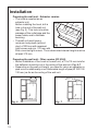
1
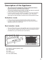
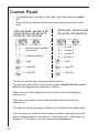
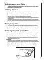
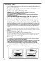
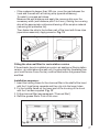
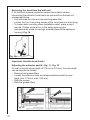
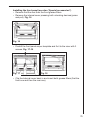
DF 6260 DF 6160 CHDF 6260 Dunstabzugshaube Afzuigkap Hotte Cooker Hood Montage- und Gebrauchsanweisung Installatie- en gebruiksaanwijzing Notice dutilisation et dinstallation Operating and Installation Instructions Contents Safety warnings .............................................................................. 62 For the user ...................................................................................... 62 For the installer ................................................................................. 63 Description of the Appliance ......................................................... 65 Extraction mode ................................................................................ 65 Recirculation mode ........................................................................... 65 Control Panel .................................................................................. 66 Maintenance and Care ................................................................... Cleaning the hood ............................................................................. Metal grease filter ............................................................................. Removing the metal grease filter ........................................................ Charcoal filter .................................................................................... Changing the light bulb(s) .................................................................. 67 67 67 67 68 69 Special accessories ........................................................................ 69 What to do if ................................................................................... 70 Technical assistance service ......................................................... 71 Service and Spare Parts .................................................................... 71 Customer Care Department ........................................................... 72 Technical Specifications ................................................................ 72 Mounting accessories included ..................................................... 72 Electrical connection ..................................................................... 73 Installation ........................................................................................ 74 61 Safety warnings For the user The cooker hood is designed to extract unpleasant odours from the kitchen, it will not extract steam. Always cover lighted elements, to prevent excess heat from damaging the appliance. In the case of oil, gas and coal fired cookers it is essential to avoid open flames. Also, when frying, keep the deep frying pan on the cooker top/cooker under careful control. The hot oil in the frying pan might ignite due to overheating. The risk of self-ignition increases when the oil being used is dirty. It is extremely important to note that overheating can cause a fire. Never carry out any flambé cooking under the hood. Always disconnect the unit from the power supply before carrying out any work on the hood, including replacing the light bulb (take the cartridge fuse out of the fuse holder or switch off the automatic circuit breaker). It is very important to clean the hood and replace the filter at the recommended intervals. Failure to do so could cause grease deposits to build up, resulting in a fire hazard. The appliance is not intended for use by young children or infirm persons without supervision. Young children should be supervised to ensure that they do not play with the appliance. WARNING - Ensure that the appliance is switched off before replacing the lamp to avoid the possibility of electric shock. This appliance is marked according to the European directive 2002/96/ EC on Waste Electrical and Electronic Equipment (WEEE). By ensuring this product is disposed of correctly, you will help prevent potential negative consequences for the environment and human health, which could otherwise be caused by inappropriate waste handling of this product. The symbol on the product, or on the documents accompanying the product, indicates that this appliance may not be treated as household waste. Instead it shall be handed over to the applicable collection point for the recycling of electrical and electronic equipment. Disposal must be carried out in accordance with local environmental regulations for waste disposal. For more detailed information about treatment, recovery and recycling of this product, please contact your local city office, your household waste disposal service or the shop where you purchased the product. 62 For the installer Only for model DF6160: when used as an extractor unit, the hood must be fitted with a 120mm diameter hose. Only for models DF 6260 - DF 6260-ml/1 and CHDF 6260: when used as an extractor unit, the hood must be fitted with a 150mm diameter hose. Only for model DF 6260 - DF 6260-ml/1: should there already be a hose of diameter 125 mm that ducts to the outside through the walls or roof, it is possible to use the 150/125 mm reduction flange provided. In this case the hood will be slightly more noisy. When installing the hood, make sure you observe the following minimum distance from the top edge of the cooking hob/ring surfaces: electric cookers 430 mm gas cookers 650 mm If the instructions for installation for the gas hob specify a greater distance, this must be adhered to. The national Standard on fuel-burning systems specifies a maximum depression of 0.04 mbar in such rooms. The air outlet must not be connected to chimney flues or combustion gas ducts. The air outlet must under no circumstances be connected to ventilation ducts for rooms in which fuel-burning appliances are installed. The air outlet installation must comply with the regulations laid down by the relevant local authorities. When the unit is used in its extractor version, a sufficiently large ventilation hole must be provided, with dimensions that are approximately the same as the outlet hole. National and regional building regulations impose a number of restrictions on using hoods and fuel-burning appliances connected to a chimney, such as coal or oil room-heaters and gas fires, in the same room. Hoods can only be used safely with appliances connected to a chimney if the room and/or flat (air/environment combination) is ventilated from outside using a suitable ventilation hole approximately 500-600 cm2 large to avoid the possibility of a depression being created during operation of the hood. If you have any doubts, contact the relevant controlling authority or building inspectors office. Since the rule for rooms with fuel burning appliances is outlet hole of the same size as the ventilation hole, a hole of 500-600 cm2, which is to say a larger hole, could reduce the performance of the extractor hood. 63 If the hood is used in its recirculation mode, it will operate simply and safely in the above conditions without the need for any of the aforementioned measures. The ducting must be fire retardant, 120mm in diameter and the length should be no more than: 3 metres with one 90 degree bend 2 metres with two 90 degree bends Bends of more than 90 degrees will reduce the efficiency of the hood and reduce the airflow. Failure to observe these basic instructions will drastically reduce the performance and increase the noise levels of the extractor hood. 64 Description of the Appliance The cooker hood is designed to extract unpleasant odours from the kitchen, it will not extract steam. The hood is supplied as an extractor unit and can also be used with a recirculation mode by fitting a charcoal filter. In some models the charcoal filter is supplied. The hood, therefore, can be used immediately in the recirculation mode. We advise removing the charcoal filter to use the hood in the extraction mode. Extraction mode In this version fumes are extracted to the outside via a hose. In order to obtain the best performance the hose should have a diameter equal to the outlet hole. Recirculation mode The air is filtered through a charcoal filter and returned to the kitchen. You will need an original charcoal filter for the recirculation function. (Available from your local Service Force Centre). Fig. 1 A = ON/OFF switches (Motor, light) B = Grease filter C = Light D = Control panel E = Visor (Removable) 65 Control Panel The switches are mounted on the upper right side of the visor (Fig. 1 - E). The numbers and symbols have the following meanings (from left to right): CHDF 6260 -ML/GB - PNC 942 120 679 DF 6260 -ML/AUS - PNC 942 120 712 DF 6260 -ML - PNC 942 120 645 = Continuously variable fan control = Intensive setting DF 6260 -ML/1 - PNC 942 120 820 DF 6160 -ML - PNC 942 120 644 1 2 3 4 = = = = fan set 1 fan set 2 fan set 3 fan set 4 = Light = Light = Light OFF = Light OFF = Light ON = Light ON The fan is controlled by moving the sliding switch. The extractor part (visor) of the hood is used to switch the fan on and off when the appliance is switched on (Motor). When the visor of the appliance is withdrawn, the fan automatically switches on. If the visor is pushed in without operating the switches, the fan is switched off. The lighting can be separately switched on and off with the slide switch. Turn the hood on a few minutes before you start cooking then you will get an underpressure in the kitchen. It should be left on after cooking for about 15 minutes or until all odours have disappeared. 66 Maintenance and Care The hood must always be disconnected from the electricity supply before beginning any maintenance work. Cleaning the hood Clean the outside of the hood using a damp cloth and a mild washing up liquid solution. Never use corrosive, abrasive or flammable cleaning products. Never insert pointed objects in the motors protective grid. Never use caustic detergents or abrasive brushes or powders. Only ever clean the switch panel and filter grill using a damp cloth and mild washing up liquid solution. It is extremely important to clean the unit and change the filters at the recommended intervals. Failure to do so will cause grease deposits to build up that could constitute a fire hazard. Metal grease filter The purpose of the grease filters is to aspirate grease particles which form during cooking and it must always be used, either in the extraction or internal recirculation function. Attention: the metal grease filters must be removed and washed, either by hand or in the dishwasher, every four weeks. Removing the metal grease filter Pull out the visor, remove the rear grease filter pulling the handle designed for this purpose, then proceed in the same way to remove the front grease filter. Fig. 2. Hand washing Soak grease filters for about one hour in hot water with a grease-loosening cleaner, then rinse off thoroughly with hot water. Repeat the process if necessary. Refit the grease filters when they are dry. Dishwasher Place grease filters in dishwasher. Select most powerful washing programme and highest temperature, at least 65°C. Repeat the process. Refit the grease filters when they are dry. When washing the metal grease filter in the dishwasher a slight discolouration of the filter can occur, this does not have any impact on its performance. Clean the inner housing using a hot detergent solution only (never use caustic detergents, abrasive powders or brushes). Fig. 2 67 Charcoal filter The charcoal filter should only be used if you want to use the hood in the recirculation function. To do this you will need an original charcoal filter (available from your local Service Force Centre). Replacing the charcoal filter Type 150 Note: this filter is already installed on model DF 6260-ml9. This filter cannot be cleaned or reused. As a general rule, the activated charcoal filter should be changed once every 4 months. Cleaning/replacing the charcoal filter Type 150 LONG LIFE Unlike other charcoal filters, the LONGLIFE charcoal filter can be cleaned and reactivated. At normal use the filter should be cleaned every second month (when using the hood 2,5 hours per day, on avarage). The best way to clean the filter is in the dishwasher. Use normal detergent and choose the highest temperature (65º C). Wash the filter separately so that no food parts gets stuck on the filter and later causes bad odours. To reactivate the charcoal, the filter should be dried in an oven for 10 minutes with a maximum temperature of 100ºC. After approximately three years of use, the charcoal filter should be replaced with a new, as the odour reduction capacity will be reduced. Fitting 1. Pull out the visor (Fig. 1 - E). 2. Remove first the rear then the front grease filters. 3. Insert the charcoal filter into the lugs of the frame above using the 2 red clips to retain it, press the red clips inwards, and insert the charcoal filter in the frame. Fig. 3. Removing: 1. Press both red lugs upwards (towards the inside of the housing) and remove the charcoal filter downwards. 2. Clean the internal housing only with warm washing-up liquid suds (never use any abrasive cleaners, brushes, or scouring agents). Always specify the hood model code number and serial number when ordering replacement filters. This information is shown on the registration plate located on the inside of the unit. The charcoal filter can be ordered from your local Service Force Centre. Fig. 3 68 Warning Failure to observe the instructions on cleaning the unit and changing the filters will cause a fire hazard. You are therefore strongly recommended to follow these instructions. The manufacturer declines all responsibility for any damage to the motor or any fire damage linked to inappropriate maintenance or failure to observe the above safety recommendations. Changing the light bulb(s) Disconnect the unit from the mains power supply. Unlock the lighting cover (D) by twisting the bolts to the left and fold down the bulb cover. Fig. 4. Replace the old light bulb(s) with a new light bulb of the same kind. Close the bulb cover and relock it by twisting the bolts to the right. If the light does not come on, make sure the bulb has been inserted correctly before contacting your local Service Force Centre. Fig. 4 D Special accessories Charcoal filter Type 150 LONG LIFE Charcoal filter Type 150 Front panel M BF6060-m Front panel AL BF6060-al Finishing strip* Clips for finishing strip (3x)* Available from your retailer as an accessory Available from your retailer as an accessory 942 120 646 942 120 647 ET-NR.: 502 426 420 02 ET-NR.: 502 302 940 06 * ET-NR. contact our Service Force Centre 69 What to do if If your appliance fails to work properly please carry out the following checks. Symptom Solution The cooker hood will not start... Check that: The hood is connected to the electricity supply. Check that a fan speed has been selected The cooker hood is not working effectively.. Check that: The fan speed is set high enough for the task. The grease filters are clean. The kitchen is adequately vented to allow the entry of fresh air. If set up for recirculation, check that the charcoal filter is still effective. If set up for extraction, check that the ducting and outlets are not blocked. The cooker hood has switched off during operation... The safety cut-out device has been tripped. Turn off the hob and then wait for the device to reset. If the hood has been installed below the heights indicated in the installation instructions the motor will cut-out frequently which will damage the hood. If after all these checks, the problem persists, contact your local Service Force Centre, quoting the model and serial number. Please note that it will be necessary to provide proof of purchase for any in-guarantee service calls. In-guarantee customers should ensure that the above checks have been made as the engineer will make a charge if the fault is not a mechanical or electrical breakdown. 70 Technical assistance service (not for UK) You are welcome to telephone our technical assistance service (see list of technical assistance centres) whenever you need information or in the unlikely event of a fault. When calling, please be ready to specify: 1. The model code number 2. The serial number (E-Nr.) 3. The manufacturing number (F-Nr.) This information is shown on the registration plate inside the unit behind the grease filter. We reserve the right to change specifications and colours as a result of our policy of continuing technological development. Service and Spare Parts In the event of your appliance requiring service, or if you wish to purchase spare parts, contact your local Service Force Centre by telephoning: 08705 929 929 Your call will be automatically routed to the Service Centre covering your post code area. For the address of your local Service Force Centre and further information about Service Force, please visit the website at www.serviceforce.co.uk Please ensure that you have read the section What to do if.... as the engineer will make a charge if the fault is not a mechanical or electrical breakdown even the appliance is under warranty. Please note that proof of purchase is required for in-guarantee service calls. Help us to help you Please determine your type of enquiry before writing or telephoning. When you contact us we need to know: Your name Clear and concise details of the fault Address and post code Name and model of the appliance* Telephone number E number* Serial number* * This information can be found on the rating plate, which can be seen when the grease filters are removed. If you require Customer Service in the Republic of Ireland please contact us at the address below: AEG Electrolux Group (Ire) Ltd Long Mile Road Dublin 12 Republic of Ireland Tel: + 353 (0) 1 4090751 Email: [email protected] 71 CUSTOMER CARE DEPARTMENT For general enquiries concerning your AEG appliance or for further information on AEG products, please contact our Customer Care Department by letter or telephone at the address below or visit our website at www.aeg.co.uk Customer Care Department AEG 55-77 High Street Slough, Berkshire SL1 1DZ 08705 950950 (*) * calls to this number may be recorded for training purposes. Technical Specifications Dimensions (in cm): Height Width Depth Maximum absorbed power: Motor absorption: Lighting: Length of the cable: Electrical connection: DF 6260 DF 6260-ml/1 CHDF 6260 DF 6160 38,7 59,9 27,5 (+ front panel) 38,7 59,9 27,5 (+ front panel) 250 W 2 x 110 2 x 9 W (PL) 150cm. 220-240V 200 W 1 x 110 2 x 40 W (E14) 150 cm 220-240V Mounting accessories included 1 Flange: Ø 150 mm (DF 6260 - DF 6260-ml/1-CHDF 6260), Ø 120 mm (DF 6160) 1 reduction flange: Ø 125-120 mm (DF 6260 - DF 6260-ml/1), Ø 125-110-100 mm (DF 6160) 1 Deflector 2 Wood-screws 2,9 x 22 mm 4 Wood-screws 4,5 x 16 mm 2 Metal-screws 3,5 x 9,5 2 Metal-screws 3,5 x 13 (DF 6260 - DF 6260-ml/1-CHDF 6260) 1 charcoal filter frame 72 Electrical connection (not for UK) Safety warnings for the electrician Before connecting the appliance to the power supply, check that the voltage indicated on the rating plate corresponds to the mains power supply available. Appliances fitted with a plug can be connected to any standard power socket within easy access. Should it be necessary to provide a fixed connection, the hood must only be installed by an electrician authorised by the local electricity board. When installing, an omnipolar disconnector with a distance of at least 3 mm between contacts must be provided. Fixed connection of the appliance must only be carried out by an authorised electrician. Electrical connection for UK only Safety warnings for the electrician Connect the hood to the mains supply via a double pole switch which has 3 mm minimum separation between the contacts. The switch must be accessible at all times. The following is valid in the United Kingdom only: - the wire which is coloured green and yellow must be connected to the terminal which is marked with the letter E or by the earth symbol ), or coloured green or green and yellow; ( - the wire which is coloured blue must be connected to the terminal which is marked with the letter N or coloured black, - the wire which is coloured brown must be connected to the terminal which is marked with the letter L or coloured red. 73 Installation Preparing the wall unit - Extractor version The hood is supplied as an extractor unit. 172 190 Before installing the hood, drill a 238 hole in the roof of the wall unit (see Fig. 5). This hole is to allow passage of the outlet pipe and the power cable, and to facilitate servicing. The wall unit must have a minimum body depth (without Fig. 5 door) of 300 mm with recessed light screen and min. 370 mm with flush-mounted light screen. The unobstructed internal height must be at least 370 mm. Preparing the wall unit - Filter version (DF 6160) Before installation of the hood in the wall unit, a 115x115 mm hole for the deflector should be cut in the ceiling of the wall unit. Fig. 6-7. Depending on the wall unit height, you need for return air operation a pipe union or additionally a non-flammable length of pipe (Ø 100/115/ 120 mm) as far as the ceiling of the wall unit. Fig. 6 74 Fig. 7 Outlet hole - Only for models DF 6260, DF 6260-ml/1 and CHDF 6260 (extractor-filter version) When used as an extractor unit, the hood must be fitted with a 150mm diameter hose. Only for model DF 6260 - DF 6260ml/1: Should there already be a pipe of diameter 125 mm that ducts to the outside through the walls or roof, it is possible to use the 150/125 mm reduction flange provided. In this case the hood will be slightly more noisy. Fix the flange on the hood outlet Fig. 8a Fig. 8b hole, using 2 screws. Fig. 8a. Filter version only Fix the deflector to the flange. Fig. 8b. Outlet hole - Only for model DF 6160(extractor-filter version) When used as an extractor unit, the hood must be fitted with a 120mm diameter hose. The dimensions and position of the air outlet are given in figure 9. Fix the flange supplied as kit onto the exit hole (bayonet fixture). Using the adapter, Ø100, Ø110 and Ø125 mm exhausting pipes can be used. Ø 125 mm exhausting hose: insert the adapter on the flange and remove, using a proper tool, the upper unused Ø 100 and Ø 110 mm rings of the adapter. Ø 110 mm exhausting pipe: same procedure, but removing the Ø 100 mm ring only. Ø 100 mm exhausting pipe: apply the adapter on the flange. A Fig. 9 Fig. 10 75 Spice rack If a spice rack is to be incorporated in front of the hood, a minimum distance of 5 mm must be provided between the front edge of the fume extractor hood and the spice rack wall (this air gap being necessary for air circulation). The upper part of the spice rack rear wall should be detachable (access for exhaust air hose or adjustment of furniture housing). Installing the extractor hood in the wall unit - extraction version (Recirculation version with charcoal filter) Fix the drilling template to the inside wall of the wall unit on the right and left sides, and mark out and predrill Ø 2 mm mounting holes as well as 2 x Ø 6 mm - 5 mm depth holes for the mounting claws (installation aids). Fully withdraw the visor of the hood. Important: Detach and insert the grease filters only when the visor is fully withdrawn. Remove the grease filters. First remove the rear and then the front grease filter. For 19 mm side walls, the spacer discs clipped in on the appliance body must be taken out. Mount the hood with 4 or 6 x Ø 4 mm screws. Fig. 11. Insert the hood in the furniture housing and engage both mounting claws (installation aids) on the right and left sides in the side wall of the wall unit and firmly hold the hood for further mounting. Then fix the hood with the 4 or 6 x Ø 4 mm screws supplied. Refit the grease filters. Push-in the visor. Fig. 11 76 If the cupboard is deeper than 300 mm, cover the gap between the hood and the wall with a finishing strip (special accessory). To install it, proceed as follows: Measure the wall distance and apply the covenng strip over the necessary width (wall distance plus 5 to 8 mm), kinking the covering strip at the appropriate notches and tearing off the surplus material (removing the protective foil). Then fasten the strip to the bottom part of the hood with three clips (special accessories). Apply pressure. Fig. 12. Fig. 12 Fitting the charcoal filter for recirculation version If the extractor hood is installed as a return air appliance (Recirculation version - air outlet above the wall unit), the charcoal filter (available from your local Service Force Centre) must be fitted before the grease filters are fitted. Installation sequence: 1. Insert the holding frame for the charcoal filter in the shaft of the hood with the 2 lugs facing upwards and then clip into the lower holes. 2. Fix the holding frame on the lower part of the housing of the hood with the 2 screws supplied. Fig. 13. 3. Fit the charcoal filter (see paragraph Charcoal filter) 4. Refit the grease filters. Push-in the visor. Fig. 13 77 Removing the hood from the wall unit If, for technical reasons (extraction version/recirculation version conversion) the extractor hood has to be removed from the wall unit, proceed as follows: Fully withdraw the visor and remove the grease filter. Loosen the 4 or 6 mounting screws of the hood (wall unit mounting). To loosen both mounting claws (installation aids), place a max 3 mm dia. Phillips screw-driver in the spring opening and simultaneously press the springs inwards (towards the appliance housing). Fig. 14. Fig. 14 Important: Hold the hood firmly! Adjusting the extractor part (E - Fig. 1) - Fig. 15 On wall units with a body depth of 275 mm to 335 mm, the visor depth can be adjusted as follows: Remove both grease filters. Loosen the screws on both end-stop brackets and set the visor depth (min. 275 mm, max. 335 mm). Refit the screws. Refit the grease filters. Fig. 15 78 Installing the front panel (see also Special accessories) Remove first the rear then the front grease filters. Remove the internal cover pressing both unlocking devices (press and pull). Fig. 16. Fig. 16 Predrill the front panel as per template and fix it to the visor with 3 screws. Fig. 17-18. Fig. 17 Fig. 18 Clip the Internal cover back in and insert both grease filters (first the front one and then the rear one). 79 From the Electrolux Group. The world´s No.1 choice. The Electrolux Group is the world´s largest producer of powered appliances for kitchen, cleaning and outdoor use. More than 55 million Electrolux Group products (such as refrigerators, cookers, washing machines,vacuum cleaners, chain saws and lawn mowers) are sold each year to a value of approx. USD 14 billion in more than 150 countries around the world. AEG 55-77 High Street SLOUGH Berks SL1 1DZ http://www.aeg.co.uk AEG Hausgeräte GmbH Postfach 1036 D-90327 Nürnberg http://www.aeg.hausgeraete.de © Copyright by AEG LI1SGK Ed. 04/05