1
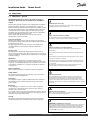
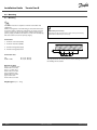
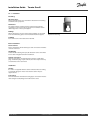
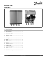
Installation Guide
Termix One-B
1.0 Table of Contents
1.0 Table of Contents ............................................. 1
2.0 Functional description...................................... 2
3.0 Safety notes..................................................... 3
3.1
Safety Notes – general . . . . . . . . . . . . . . . . . . . . . . . . . . . . . . . . . . . . . . . . . . . . 3
4.0 Mounting ........................................................ 4
4.1
Mounting . . . . . . . . . . . . . . . . . . . . . . . . . . . . . . . . . . . . . . . . . . . . . . . . . . . . . . . . . . . 4
5.0 Design............................................................. 6
5.1
5.2
Design . . . . . . . . . . . . . . . . . . . . . . . . . . . . . . . . . . . . . . . . . . . . . . . . . . . . . . . . . . . . . . . 6
Schematic diagram . . . . . . . . . . . . . . . . . . . . . . . . . . . . . . . . . . . . . . . . . . . . . . . . 7
6.0 Controls .......................................................... 9
6.1
6.2
DHW temperature control. . . . . . . . . . . . . . . . . . . . . . . . . . . . . . . . . . . . . . . . 9
Maintenance. . . . . . . . . . . . . . . . . . . . . . . . . . . . . . . . . . . . . . . . . . . . . . . . . . . . . . . . 10
7.0 Troubleshooting .............................................. 11
7.1
7.2
7.3
Troubleshooting in general . . . . . . . . . . . . . . . . . . . . . . . . . . . . . . . . . . . . . . 11
Troubleshooting DHW . . . . . . . . . . . . . . . . . . . . . . . . . . . . . . . . . . . . . . . . . . . . 11
Disposal . . . . . . . . . . . . . . . . . . . . . . . . . . . . . . . . . . . . . . . . . . . . . . . . . . . . . . . . . . . . . 12
8.0 Declaration...................................................... 15
8.1
Declaration of conformity . . . . . . . . . . . . . . . . . . . . . . . . . . . . . . . . . . . . . . . . 15
Danfoss Heating
VI.CW.J3.02 / LUK38000
DEN-GT
1
Installation Guide
Termix One-B
2.0 Functional description
Instantaneous water heater with heat exchanger and
thermostatic control. Designed for wallmounting.
Application
The Termix One is an instantaneous water heater featuring superb
heat extraction and high performance. The Termix One is suitable
for flats, single-family houses as well as for small apartment
buildings with up to 10 apartments. The water heater is available in
three sizes, either for 1 apartment, for 1‑4 apartments or for 5 up
to 10 apartments. The Termix One is applicable for decentralized
heating systems – as well as for district heating networks with
summer operation at low temperatures or changes in differential
pressure. The Termix One heat exchanger cools out the district
heating water very efficiently, thereby creating a very good
operation economy.
Domestic hot water (DHW)
The domestic hot water is prepared in the heat exchanger and
the temperature is regulated with a thermostatic control valve.
The patented sensor accelerator accelerates the closing of the
Danfoss AVTB valve and protects the heat exchanger against
overheating and lime scale formation. The sensor accelerator and
AVTB valve also works as a bypass keeping the house supply line
warm. This shortens the waiting periods during summer when the
heating system is in reduced operation. The sensor accelerator
helps to ensure a stable hot water temperature by varying loads,
flow temperatures and differential pressure without the need for
readjusting the valve. There is no additional pressure loss on the
secondary side of the DHW heat exchanger with a thermostatic
control. Therefore this type of regulation can be used by low
pressure on the in the cold water mains.
2
DEN-GT
VI.CW.J3.02 / LUK38000
Danfoss Heating
Installation Guide
Termix One-B
3.0 Safety notes
3.1 Safety Notes – general
The following instructions refer to the standard design of
substation. Special versions of substations are available on
request.
This operating manual should be read carefully before installation
and start-up of the substation. The manufacturer accepts no
liability for damage or faults that result from non-compliance with
the operating manual. Please read and follow all the instructions
carefully to prevent accidents, injury and damage to property.
Assembly, start-up and maintenance work must be performed by
qualified and authorized personnel only.
Please comply with the instructions issued by the system
manufacturer or system operator.
Corrosion protection
All pipes and components are made of stainless steel and brass.
The maximum chloride compounds of the flow medium should not
be higher than 150 mg/l.
The risk of equipment corrosion increases considerably if the
recommended level of permissible chloride compounds is
exceeded.
Energy source
The substation is designed for district heating as the primary
source of energy. However, also other energy sources can be used
where the operating conditions allow it and always are comparable
to district heating.
Application
The substation is designed to be connected to the house
installation in a frost-free room, where the temperature does not
exceed 50 °C and the humidity does not exceed 60%. Do not cover
or wall up the substation or in any other way block the entrance
to the station.
Authorized personnel only
Assembly, start-up and maintenance work must be performed by
qualified and authorized personnel only.
Please observe instructions carefully
To avoid injury to persons and damage to the device, it is absolutely
necessary to read and observe these instructions carefully.
Warning of high pressure and temperature
Be aware of the installation’s permissible system pressure and
temperature.
The maximum temperature of the flow medium in the substation is
120 °C.
The maximum operating pressure of the substation is 10 bar. PN 16
versions are available on enquiry.
The risk of persons being injured and equipment damaged increases
considerably if the recommended permissible operating parameters
are exceeded.
The substation installation must be equipped with safety valves,
however, always in accordance with local regulations.
Choice of material
Choice of materials always in compliance with local legislation.
Safety valve(s)
We recommend mounting of safety valve(s), however, always in
compliance with local regulations.
Connection
The substation must be equipped with features that ensure that
the substation can be separated from all energy sources (also
power supply).
Warning of hot surface
The substation has got hot surfaces, which can cause skin burns.
Please be extremely cautious in close proximity to the substation.
Power failure can result in the motor valves being stuck in open
position. The surfaces of the substation can get hot, which can cause
skin burns. The ball valves on district heating supply and return should
be closed.
Emergency
In case of danger or accidents - fire, leaks or other dangerous
circumstances - interrupt all energy sources to the station if
possible, and seek expert help.
In case of discoloured or bad-smelling domestic hot water, close all
shut-off valves on the substation, inform the operating personnel
and call for expert help immediately.
Warning of transport damage
Before substation installation, please make sure that the substation
has not been damaged during transport.
Storage
Any storage of the substation which may be necessary prior to
installation should be in conditions which are dry and heated.
IMPORTANT - Tightening of connections
Due to vibrations during transport all flange connections, screw joints
and electrical clamp and screw connections must be checked and
tightened before water is added to the system. After water has been
added to the system and the system has been put into operation,
re-tighten ALL connections.
Danfoss Heating
VI.CW.J3.02 / LUK38000
DEN-GT
3
Installation Guide
Termix One-B
4.0 Mounting
4.1 Mounting
Installation must be in compliance with local standards and
regulations.
District heating (DH) - In the following sections, DH refers to the
heat source which supplies the substations. A variety of energy
sources, such as oil, gas or solar power, could be used as the
primary supply to Danfoss substations. For the sake of simplicity,
DH can be taken to mean the primary supply.
Authorized personnel only
Assembly, start-up and maintenance work must be performed by
qualified and authorized personnel only.
Connections:
1. Domestic cold water (DCW)
2. Domestic hot water (DHW)
3. District heating (DH) supply
4. District heating (DH) return
Connection sizes:
DH:
DCW + DHW:
G ¾” (int. thread)
G ¾” (int. thread)
The pipe placement can deviate from the shown drawing. Please note
the markings on the station.
Dimensions (mm):
Type 1 + 2 without cover:
H 428 x W 312 x D 155
Type 1 + 2 with cover:
H 430 x W 315 x D 165
Type 3 without cover:
H 468 x W 312 x D 155
Type 3 with cover:
H 470 x W 315 x D 165
Weight (approx.): 10 – 12 kg
4
DEN-GT
VI.CW.J3.02 / LUK38000
Danfoss Heating
Installation Guide
Termix One-B
4.1.1 Installation
Mounting:
Adequate space
Please allow adequate space around the substation for mounting
and maintenance purposes.
Orientation
The station must be mounted so that components, keyholes
and labels are placed correctly. If you wish to mount the station
differently please contact your supplier.
Drillings
Where substations are to be wall-mounted, drillings are provided
in the back mounting plate. Floor mounted units have support.
Keyhole for mounting.
Labelling
Each connection on the substation is labelled.
Before installation:
Clean and rinse
Prior to installation, all substation pipes and connections should be
cleaned and rinsed.
Thightening
Due to vibration during transport, all substation connections must
be checked and tightened before installation.
Unused connections
Unused connections and shut-off valves must be sealed with a
plug. Should the plugs require removal, this must only be done by
an authorized service technician.
Installation:
Strainer
If a strainer is supplied with the station it must be fitted according
to schematic diagram. Please note that the strainer may be
supplied loose.
Connections
Internal installation and district heating pipes connections must be
made using threaded, flanged or welded connections.
Danfoss Heating
VI.CW.J3.02 / LUK38000
DEN-GT
5
Installation Guide
Termix One-B
5.0 Design
5.1 Design
Your substation might look different than the substation shown.
Design description
B Heat exchanger, DHW
O Termix sensor accelerator
7 Thermostatic controller, DHW
6
DEN-GT
VI.CW.J3.02 / LUK38000
Danfoss Heating
Installation Guide
Termix One-B
5.2 Schematic diagram
DH
Supply
DHW
DH
Return
DCW
DH
Supply
DHW
HWC
DH
Return
DCW
Your substation might look different than the schematic diagram shown.
First diagram: Termix One-B – with GTU.
Second diagram: Termix One-B – with safety valve.
Schematic description
B
2
4
6
Heat exchanger, DHW
Single check valve
Safety valve
Thermostatic/non-return valve
DHW:
DCW:
HWC:
DH Supply:
DH Return:
Danfoss Heating
7 Thermostatic valve
21 To be ordered separately
62 GTU Pressure equalizer
Domestic Hot Water
Domestic Cold Water
Hot Water Circulation
District Heating Supply
District Heating Return
VI.CW.J3.02 / LUK38000
DEN-GT
7
Installation Guide
Termix One-B
5.2.1 Technical parameters
Technical parameters
Nominal pressure:
Max. DH supply temperature:
Min. DCW static pressure:
Brazing material (HEX):
Heat exchangers test pressure:
Sound level:
8
DEN-GT
PN 16
120 °C
0.5 bar
Copper
30 bar
≤ 55 dB
VI.CW.J3.02 / LUK38000
Danfoss Heating
Installation Guide
Termix One-B
6.0 Controls
6.1 DHW temperature control
DHW temperature control
There are various types of DHW temperature control used in
Danfoss substations.
DHW temperature should be adjusted to 45-50 °C, as this provides
optimal utilisation of DH water. At DHW temperatures above 55 °C,
the possibility of lime scale deposits increases significantly.
6.1.1 AVTB controller (20–60 °)
The temperature setting is as follows:
1 = 20 °C
2 = 35 °C
3 = 50 °C
4 = 60 °C
5 = 70 °C
The values are intended as a guide.
The AVTB operates at its best at DH supply temperatures of up to
90 °C.
Thermostatic control
DHW temperature is adjusted as follows:
To increase temperature, turn the handle on the thermostatic
controller to select a higher number.
To decrease temperature, turn the handle on the thermostatic
controller to select a lower number.
6.1.2 Safety valve
The purpose of the safety valve is to protect the substation from
excessive pressure.
The blow-off pipe from the safety valve must not be closed. The
blow-off pipe outlet should be placed so that it discharges freely
and it is possible to observe any dripping from the safety valve.
It is recommended to check the operation of safety valves at
intervals of 6 months. This is done by turning the valve head in
direction indicated.
Danfoss Heating
VI.CW.J3.02 / LUK38000
DEN-GT
9
Installation Guide
Termix One-B
6.1.3 Strainer
Strainers should be cleaned regularly by authorized personnel. The
frequency of cleaning would depend on operating conditions and
the manufacturer’s instructions.
6.1.4 GTU Pressure Equalizer
The GTU Pressure Equalizer absorbs the expansion on the
secondary side of the Termix water heaters and can be used as a
substitute to the safety valve.
Furthermore the pressure equalizer absorbs a possible increase in
pressure, so a discharge outlet is omitted.
The GTU Pressure Equalizer may not be applied in systems with hot
water circulation.
6.2 Maintenance
The substation requires little monitoring, apart from routine
checks. It is recommended to read the energy meter at regular
intervals, and to write down the meter readings.
Regular inspections of the substation according to this Instruction
are recommended, which should include:
Authorized personnel only
Assembly, start-up and maintenance work must be performed by
qualified and authorized personnel only.
Strainers
Cleaning of strainers.
Meters
Checking of all operating parameters such as meter readings.
Temperatures
Checking of all temperatures, such as DH supply temperature and
DHW temperature.
Connections
Checking all connections for leakages.
Safety valves
The operation of the safety valves should be checked by turning
the valve head in the indicated direction.
Venting
Checking that the system is thoroughly vented.
Inspections should be carried out minimum every two years.
Spare parts can be ordered from Danfoss. Please ensure that any
enquiry includes the substation serial number.
10
DEN-GT
VI.CW.J3.02 / LUK38000
Danfoss Heating
Installation Guide
Termix One-B
7.0 Troubleshooting
7.1 Troubleshooting in general
In the event of operating disturbances, the following basic features
should be checked before carrying out actual troubleshooting:
•
the substation is connected to electricity,
•
the strainer on the DH supply pipe is clean,
•
the supply temperature of the DH is at the normal level
(summer, at least 60 °C - winter, at least 70 °C),
•
the differential pressure is equal to or higher than the normal
(local) differential pressure in the DH network – if in doubt, ask
the DH plant supervisor,
•
pressure on the system - check the HE pressure gauge.
Authorized personnel only
Assembly, start-up and maintenance work must be performed by
qualified and authorized personnel only.
7.2 Troubleshooting DHW
Problem
Possible cause
Solution
Too little or no DHW.
Strainer in supply or return line clogged.
Clean strainer(s).
DHW circulation pump out of order or with
too low setting.
Check circulation pump.
Defective or clogged non-return valve.
Replace – clean.
No electricity.
Check.
Wrong setting of automatic controls, if any.
To adjust an electronic controller for
DHW, pls. note enclosed instructions for
electronic controller.
Scaling of the plate heat exchanger.
Replace – rinse out.
Defective motorized valve.
Check (use manual function) – replace.
Defective temperature sensors.
Check – replace.
Defective controller.
Check – replace.
DCW is being mixed with the DHW, e.g. in
a defective thermostatic mixing valve.
Check – replace.
Defective or clogged non-return valve on
circulation valve.
Replace – clean.
Tap temperature too high; DHW tap load
too high.
Thermostatic valve adjusted to a too high
level.
Check – set.
Temperature drop during tapping.
Scaling of the plate heat exchanger.
Replace – rinse out.
Larger DHW flow than the substation has
been designed for.
Reduce DHW flow.
Temperature difference between DH
supply and DHW set point too low.
Lower the set point temperature or
increase the DH supply temperature.
Hot water in some taps but not in all.
Thermostatic control valve does not close
Danfoss Heating
VI.CW.J3.02 / LUK38000
DEN-GT
11
Installation Guide
Termix One-B
7.3 Disposal
Disposal
This product should be dismantled and its components
sorted, if possible, in various groups before recycling
or disposal.
Always follow the local disposal regulations.
12
DEN-GT
VI.CW.J3.02 / LUK38000
Danfoss Heating
Installation Guide
Danfoss Heating
Termix One-B
VI.CW.J3.02 / LUK38000
DEN-GT
13
Installation Guide
14
DEN-GT
Termix One-B
VI.CW.J3.02 / LUK38000
Danfoss Heating
Installation Guide
Termix One-B
8.0 Declaration
8.1 Declaration of conformity
8.1.1 Category 0 without electrical equipment
EC – Declaration of Conformity
Gemina Termix A/S
Member of the Danfoss Group
Navervej 15-17
DK-7451 Sunds
Declares on our sole responsibility that the below products:
Substations – Category 0 without electrical equipment,
covered by this declaration are in conformity with the following directives, standards and other normative
documents, provided that they are used according to our instructions.
Machinery Directive 2006/42/EC
DS/EN 60204-1/A1:2009. Safety of machinery –
Part 1 – General Requirements.
DS/EN 12100:2011. Safety of machinery – Risk
assessment.
Sunds – 2013.03.15
Place and date of issue
Danfoss Heating
Claus Gjøderum Mortensen
Quality & Environment Manager
VI.CW.J3.02 / LUK38000
DEN-GT
15
Installation Guide
Termix One-B
Produced by Danfoss A/S © 11/2013