1
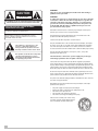
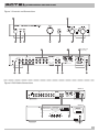
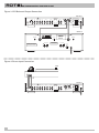
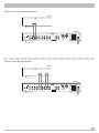
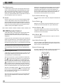
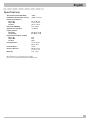
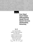
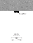
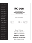
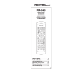
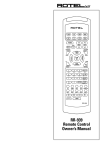
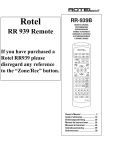
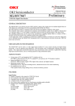
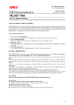
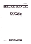
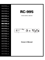
RC-995
STEREO CONTROL AMPLIFIER
Owner’s Manual
CAUTION
RISK OF ELECTRIC SHOCK
DO NOT OPEN
CAUTION: TO REDUCE THE RISK OF ELECTRIC SHOCK, DO
NOT REMOVE COVER. NO USER-SERVICEABLE PARTS INSIDE.
REFER SERVICING TO QUALIFIED SERVICE PERSONNEL.
APPLICABLE FOR USA, CANADA OR WHERE
APPROVED FOR THE USAGE
WARNING:
There are no user serviceable parts inside. Refer all servicing to
qualified service personnel.
WARNING:
To reduce the risk of fire or electrical shock, do not expose the unit
to moisture or water. Do not allow foreign objects to get into the
enclosure. If the unit is exposed to moisture, or a foreign object
gets into the enclosure, immediately disconnect the power cord
from the wall. Take the unit to a qualified service person for inspection and necessary repairs.
CAUTION: TO PREVENT ELECTRIC SHOCK, MATCH WIDE BLADE
OF PLUG TO WIDE SLOT. INSERT FULLY.
Read all the instructions before connecting or operating the unit. Keep this
manual so you can refer to these safety instructions.
ATTENTION: POUR EVITER LES CHOCS ELECTRIQUES,
INTRODUIRE LA LAME LA PLUS LARGE DE LA FICHE
DANS LA BORNE CORRESPONDANTE DE LA PRISE ET
POUSSER JUSQU AU FOND.
Heed all warnings and safety information in these instructions and on the
product itself. Follow all operating instructions.
Clean the unit only with a dry cloth or a vacuum cleaner.
This symbol is to alert the user to the
presence of uninsulated dangerous
voltages inside the product's enclosure
that may constitute a risk of electric shock.
This symbol is to alert the user to important
operating and maintenance (service)
instructions in this manual and literature
accompanying the product.
Keep the ventilation inlets on the unit unobstructed. For example, do not place
the unit on a bed, sofa, rug, or similar surface that could block the ventilation
slots. If the unit is placed in a bookcase or cabinet, there must be sufficient
clearance around the unit and ventilation of the cabinet to allow proper cooling.
Keep the unit away from radiators, heat registers, stoves, or any other
appliance that produces heat.
The unit must be connected to a power supply only of the type
and voltage specified on the rear panel of the unit.
Connect the unit to the power outlet only with the supplied 2-pin polarized
power supply cable or an exact equivalent. Do not modify the supplied cable in
any way. Do not attempt to defeat grounding and/or polarization provisions. The
cable should be connected to a 2-pin polarized wall outlet, matching the wide
blade of the plug to the wide slot of the receptacle. Do not use extension cords.
Do not route the power cord where it will be crushed, pinched, bent at severe
angles, exposed to heat, or damaged in any way. Pay particular attention to the
power cord at the plug and where it exits the back of the unit.
The power cord should be unplugged from the wall outlet if the unit is to be left
unused for a long period of time.
Immediately stop using the unit and have it inspected and/or serviced by a
qualified service agency if:
•
•
•
•
•
The power supply cord or plug has been damaged.
Objects have fallen, or liquid has been spilled, into the unit.
The unit has been exposed to rain.
The unit shows signs of improper operation
The unit has been dropped or damaged in any way
Place the unit on a fixed, level surface strong
enough to support its weight. Do not place the
unit on a moveable cart that could tip over.
STEREO CONTROL AMPLIFIER RC-995
Figure 1: Controls and Connections
1
7
2
3
4
5
6
9
8
American
17 North
version only
16
13
MODEL NO. RC-995
PHONO
CD
VIDEO
TUNER
AUX
TAPE 1
TAPE 2
OUTPUTS
POWER
R
MM
LEFT
MC
RIGHT
IN
10
11
OUT
IN
OUT
L
LEFT
RIGHT
SERIAL NO.
ON
1
SWITCHED 800W MAX
18
15
14
12
OFF
BALANCED OUTPUTS
2
○ ○ ○ ○ ○ ○ ○ ○ ○ ○ ○ ○ ○ ○ ○ ○ ○ ○ ○ ○ ○ ○ ○ ○ ○ ○ ○ ○ ○ ○ ○ ○ ○ ○ ○ ○ ○ ○ ○ ○ ○ ○ ○ ○ ○ ○ ○ ○ ○ ○ ○ ○ ○ ○ ○ ○ ○ ○ ○ ○ ○ ○ ○ ○ ○ ○ ○ ○
Figure 2: RCA Cable Connections
ROTEL RC-995
MODEL NO. RC-995
PHONO
CD
VIDEO
TUNER
AUX
TAPE 1
TAPE 2
OUTPUTS
POWER
R
MM
LEFT
MC
RIGHT
IN
OUT
IN
OUT
L
LEFT
RIGHT
SERIAL NO.
ON
1
2
OFF
BALANCED OUTPUTS
SWITCHED 600W MAX
ROTEL RB-981
WARNING:TO REDUCE THE RISK OF FIRE
SPEAKER IMPEDANCE
OR ELECTRICAL SHOCK, DO NOT EXPOSE
STEREO 4 OHMS MINIMUM
THIS EQUIPMENT TO RAIN OR MOISTURE.
BRIDGED 8 OHMS MINIMUM
CAUTION
RISK OF ELECTRIC SHOCK
DO NOT OPEN
AVIS: RISQUE DE CHOC ELECTRIQUE–NE PAS OUVRIR
POWER AMPLIFIER
MODEL NO. RB-981
POWER CONSUMPTION: 400W
SPEAKERS
RIGHT
RIGHT INPUT
LEFT
LEFT INPUT
SERIAL NO.
STEREO CONTROL AMPLIFIER RC-995
Figure 3: XLR Balanced Output Connection
ROTEL RC-995
MODEL NO. RC-995
PHONO
CD
VIDEO
TUNER
AUX
TAPE 1
TAPE 2
OUTPUTS
POWER
R
MM
LEFT
MC
RIGHT
IN
OUT
IN
OUT
L
LEFT
RIGHT
ON
1
SERIAL NO.
OFF
BALANCED OUTPUTS
2
SWITCHED 600W MAX
ROTEL RB-991
CAUTION
RIGHT INPUT
LEFT INPUT
POWER AMPLIFIER
MODEL NO. RB-991
POWER CONSUMPTION: 550W
RISK OF ELECTRIC SHOCK
DO NOT OPEN
BALANCED
AVIS: RISQUE DE CHOC ELECTRIQUE–NE PAS OUVRIR
UNBALANCED
BALANCED
UNBALANCED
RB-991
BALANCED
UNBALANCED
RIGHT SPEAKER
LEFT SPEAKER
SPEAKER IMPEDANCE
4 OHMS MINIMUM
WARNING:TO REDUCE THE RISK OF FIRE
AC FUSE
10 A AGC
OR ELECTRICAL SHOCK, DO NOT EXPOSE
THIS EQUIPMENT TO RAIN OR MOISTURE.
F US E
○ ○ ○ ○ ○ ○ ○ ○ ○ ○ ○ ○ ○ ○ ○ ○ ○ ○ ○ ○ ○ ○ ○ ○ ○ ○ ○ ○ ○ ○ ○ ○ ○ ○ ○ ○ ○ ○ ○ ○ ○ ○ ○ ○ ○ ○ ○ ○ ○ ○ ○ ○ ○ ○ ○ ○ ○ ○ ○ ○ ○ ○ ○ ○ ○ ○ ○ ○
Figure 4: Phono Input Connection
PH0NO
GND
L
R
ROTEL RC-995
MODEL NO. RC-995
PHONO
CD
VIDEO
TUNER
AUX
TAPE 1
TAPE 2
OUTPUTS
POWER
R
MM
LEFT
MC
RIGHT
IN
OUT
IN
OUT
L
LEFT
RIGHT
SERIAL NO.
ON
1
2
OFF
BALANCED OUTPUTS
SWITCHED 600W MAX
Figure 5: Line Level Input Connection
CD PLAYER
OUTPUT
L
R
ROTEL RC-995
MODEL NO. RC-995
PHONO
CD
VIDEO
TUNER
AUX
TAPE 1
TAPE 2
OUTPUTS
POWER
R
MM
LEFT
MC
RIGHT
IN
OUT
IN
OUT
L
LEFT
RIGHT
SERIAL NO.
ON
1
OFF
BALANCED OUTPUTS
2
SWITCHED 600W MAX
○ ○ ○ ○ ○ ○ ○ ○ ○ ○ ○ ○ ○ ○ ○ ○ ○ ○ ○ ○ ○ ○ ○ ○ ○ ○ ○ ○ ○ ○ ○ ○ ○ ○ ○ ○ ○ ○ ○ ○ ○ ○ ○ ○ ○ ○ ○ ○ ○ ○ ○ ○ ○ ○ ○ ○ ○ ○ ○ ○ ○ ○ ○ ○ ○ ○ ○ ○
Figure 6: Recorder Connections
RECORDER
OUTPUT
L
R
INPUT
L
R
ROTEL RC-995
MODEL NO. RC-995
PHONO
CD
VIDEO
TUNER
AUX
TAPE 1
TAPE 2
OUTPUTS
POWER
R
MM
LEFT
MC
RIGHT
IN
OUT
IN
OUT
L
LEFT
RIGHT
SERIAL NO.
ON
1
2
OFF
BALANCED OUTPUTS
SWITCHED 600W MAX
STEREO CONTROL AMPLIFIER RC-995
○ ○ ○ ○ ○ ○ ○ ○ ○ ○ ○ ○ ○ ○ ○ ○ ○ ○ ○ ○ ○ ○ ○ ○ ○ ○ ○ ○ ○ ○ ○ ○ ○
○ ○ ○ ○ ○ ○ ○ ○ ○ ○ ○ ○ ○ ○ ○ ○ ○ ○ ○ ○ ○ ○ ○ ○ ○ ○ ○ ○ ○ ○ ○ ○ ○
Contents (circled numbers refer to illustration)
About Rotel
About Rotel __________________________________________ 1
Getting Started ______________________________________ 2
A Few Precautions
2
Placement
2
Cables
2
AC Power and Control ________________________________ 2
AC Power Input 18
2
Power/Standby Switch 2 and Power Indicator 1
3
Auxiliary Power Outputs 17
3
Input Signal Connection ______________________________ 3
Phono Input Selector Switch 10
3
Phono Input Connection 11
3
Line Level Inputs 12
3
Recorder Connections 13 ____________________________ 3
Output Connections __________________________________ 3
Balanced Output Switch 15
3
RCA Outputs 14
4
Balanced XLR Outputs 16
4
Front Panel Controls __________________________________ 4
Volume Control 5
4
Balance Control 6
4
4
Listening Selector 9
Recording Selector
8 and Indicator
7
4
Phones Output 3
4
Remote Sensor 4
4
Troubleshooting ______________________________________ 4
Standby Power Indicator Is Not Lit
4
Fuse Replacement
5
No Sound
5
RR-939 Remote Control _______________________________ 5
Programming the Remote Control
5
Device Selector Buttons 19
5
Power Button 20
5
Volume Buttons 21
5
Mute Button 22
5
Input Select Buttons 24
5
Numeric Buttons 23
5
Specifications ________________________________________ ?
1
A family whose passionate interest in music led them to manufacture high fidelity components of uncompromising quality founded
Rotel over 30 years ago. Through the years that passion has remained undiminished and the family goal of providing exceptional
value for audiophiles and music lovers, regardless of their budget,
is shared by all Rotel employees.
The engineers work as a close team, listening to, and fine tuning
each new product until it reaches their exacting musical standards. They are free to choose components from around the
world in order to make that product the best they can. You are
likely to find capacitors from the United Kingdom and Germany,
semi conductors from Japan or the United States, while toroidal
power transformers are manufactured in Rotel’s own factory.
Rotel’s reputation for excellence has been earned through hundreds of good reviews and awards from the most respected reviewers in the industry, who listen to music every day. Their
comments keep the company true to its goal – the pursuit of
equipment that is musical, reliable and affordable.
All of us at Rotel thank you for buying this product and hope it will
bring you many hours of enjoyment.
English
○ ○ ○ ○ ○ ○ ○ ○ ○ ○ ○ ○ ○ ○ ○ ○ ○ ○ ○ ○ ○ ○ ○ ○ ○ ○ ○ ○ ○ ○ ○ ○ ○
Getting Started
Thank you for purchasing the Rotel RC-995 Stereo Control Amplifier. When used in a high-quality music or home theater system, it
will provide years of musical enjoyment.
The RC-995 is a full featured, high performance preamplifier. All
aspects of the design have been optimized to retain the full dynamic range and subtle nuances of your music. The RC-995 has a
highly regulated power supply incorporating a Rotel custom-designed toroidal power transformer and custom-made slit foil capacitors. This low impedance power supply has ample power
reserves, which enables the RC-995 to easily reproduce the most
demanding audio signals. This type of design is more expensive to
manufacture, but it is better for the music.
The RC-995 has both XLR (balanced) and RCA cable main output
connections. The printed circuit boards (PCB) are designed with
Symmetrical Circuit Traces. This insures that the precise timing of
the music is maintained and faithfully recreated. The RC-995 circuitry uses metal film resistors and polystyrene or polypropylene
capacitors in important signal paths. All aspects of this design
have been examined with the final goal being faithful reproduction
of music.
The RC-995 has a superb phono preamp stage, derived from
Rotel’s finest phono preamplifier, the RHQ 10. The preamp stage
can be used with either a moving magnet (MM) or a moving coil
(MC) phono cartridge. This shows our commitment to phono
sound quality and our interest in the recreation of fine music.
The RC-995 is straightforward in its installation and operation. If
you have experience with other stereo systems, you shouldn’t find
anything perplexing. Simply plug in the associated components
and enjoy.
Placement
Like all audio components that handle low-level signals, the RC995 can be affected by its environment. Do not stack the RC-995
on top of a power amplifier. This will minimize chance it will pick
up hum or interference. We recommend installing the RC-995 in
furniture designed to house audio components. Such furniture is
designed to reduce or suppress vibration which can adversely affect sound quality. Ask your authorized Rotel dealer for advice
about component furniture and proper installation of audio components.
Cables
Be sure to keep the power cords, digital signal cables and regular
audio signal cables in your installation away from each other. This
will minimize the chance of the regular audio signal cables picking up noise or interference from the power cords or digital
cables. Using only high quality, shielded cables will also help to
prevent noise or interference from degrading the sound quality of
your system. If you have any questions see your authorized Rotel
dealer for advice about the best cable to use with your system
○ ○ ○ ○ ○ ○ ○ ○ ○ ○ ○ ○ ○ ○ ○ ○ ○ ○ ○ ○ ○ ○ ○ ○ ○ ○ ○ ○ ○ ○ ○ ○ ○
AC Power and Control
AC Power Input
18
The RC-995 does not use a significant amount of power. However
there are two auxiliary power outlets on the back of the unit,
which can be used to supply power for other units. Consequently
it is usually best to plug the RC-995 directly into a 2-pin polarized
wall outlet. Avoid the use of extension cords. A heavy duty multitap power outlet strip may be used if it (and the wall outlet) is
rated to handle the current demanded by the components connected to it.
A Few Precautions
Please read this manual carefully. It provides complete information on how to incorporate the RC-995 into your system as well as
general information that will help you get optimum sound performance. Please contact your authorized Rotel audio retailer for answers to any questions you might have. In addition, all of us at
Rotel welcome your questions and comments.
Save the RC-995 shipping carton and all enclosed packing material for future use. Shipping or moving the RC-995 in anything other
than the original packing material may result in severe damage to
your amplifier.
Fill out and send in the owner’s registration card packed with the
RC-995. Also be sure to keep the original sales receipt. It is your
best record of the date of purchase, which you will need in the
event warranty service is ever required.
Note: Do not connect the power cord for a power amplifier to the
auxiliary power outlets on the RC-995. Power amplifiers often
draw more power than these outlets can provide.
Be sure the power switch on the front panel of the RC-995 is
turned off (LED indicator is off). Then, connect the supplied power
cord to the AC power outlet.
Your RC-995 is configured at the factory for the proper AC line
voltage in the country where you purchased it (either 115 volts AC
or 230 volts AC with a line frequency of either 50 Hz or 60 Hz). The
AC line configuration is noted on a decal on the left side.
Note: Should you move your RC-995 amplifier to another country, it
is possible to reconfigure your amplifier for use on a different line
voltage. Do not attempt to perform this conversion yourself. Opening the enclosure of the RC-995 exposes you to dangerous voltages. Consult a qualified service person or the Rotel factory
service department for information.
2
STEREO CONTROL AMPLIFIER RC-995
If you are going to be away from home for an extended period of
time such as a month-long vacation, it is a sensible precaution to
unplug your amplifier (as well as other audio and video components) while you are away.
Power/Standby Switch
2
and Power Indicator
17
The North American version of the RC-995 has two switched outlets on the back panel. Power is available from these outlets when
the RC-995 is playing. Power to these outlets is turned off when
the RC-995 is in Standby mode. These outlets can provide up to a
total of 800 watts. They are appropriate for supplying power to
signal sources, such as CD players, tuners, or tape decks. They
should not be used for power amplifiers. Connecting components
that will draw more than 800 watts to these outputs could damage
the Standby switch in the RC-995.
○ ○ ○ ○ ○ ○ ○ ○ ○ ○ ○ ○ ○ ○ ○ ○ ○ ○ ○ ○ ○ ○ ○ ○ ○ ○ ○ ○ ○ ○ ○ ○ ○
Input Signal Connections
11
and
12
[See Figure 4 for phono input connection illustration.]
The RC-995 has conventional RCA type input connectors, the type
found on nearly all audio equipment.
Note: To prevent loud noises that neither you nor your speakers
will appreciate, make sure the system is turned off when you
make any signal connections.
Phono Input Selector Switch 10
The Phono input is for a moving magnet (MM) or moving coil (MC)
phono cartridge only and is incompatible with line level components. Set the phono input selector switch 10 as appropriate for
the phono cartridge you are using. Leave the switch button in the
out position for a moving magnet cartridge; push the switch in for
a moving coil cartridge. Some high output moving coil cartridges
are designed to operate in the moving magnet position. If you are
in doubt about the correct setting, check the instruction manual
for your phono cartridge for information regarding its output voltage and the expected input impedance. The Phono input has 47
kOhms input impedance and 2.5 mV sensitivity in the MM position
and 100 Ohms input impedance and 0.25 mV sensitivity in the MC
position. If you still have questions about the proper setting of the
phono input selector switch, consult your authorized Rotel dealer.
3
Plug the cable from the turntable into the appropriate left and
right phono inputs. Typically turntables have a “ground” wire.
Connect this wire to the screw terminal to the left of the Phono inputs. It will help prevent hum and noise.
1
The Power/Standby switch is located on the left side of the front
panel. When it is pressed the RC-995 is turned on and the function
indicator lights are illuminated. Pressing the Standby switch again
will make put the RC-995 in “standby” mode and the function indicators are turned off. The Power Indicator light above the Standby
button is always illuminated when the RC-995 is connected to a
“live” AC outlet.
Auxiliary Power Outputs
Phono Input Connection 11
Line Level Inputs
12
[See Figure 5 for line level input connection illustration.]
The CD, Video, Tuner, and Aux inputs of the RC-995 are “line level”
inputs. These are for connecting components such as CD players,
Hi Fi or NICAM Stereo video cassette recorders, tuners for audio
or video, Laser Disc players or the analog output from a CD ROM
drive.
The Left and Right channels are clearly labeled and should be
connected to the corresponding channels of the source component. Use high quality RCA cables for connecting input source
components to the RC-995. Ask your authorized Rotel dealer for
advice about cables.
○ ○ ○ ○ ○ ○ ○ ○ ○ ○ ○ ○ ○ ○ ○ ○ ○ ○ ○ ○ ○ ○ ○ ○ ○ ○ ○ ○ ○ ○ ○ ○ ○
Recorder Connections
13
[See Figure 6 for recorder connection illustration.]
The Tape 1 and Tape 2 inputs and outputs can be connected to
any record/playback device that accepts standard line level analog input and output signals. Typically that will be a conventional
tape recorder. However it could also be a digital audio tape recorder or some other future format.
When connecting a recorder to the RC-995 remember that the outputs of the recorder must be connected to the tape inputs of the
RC-995. Similarly the tape outputs of the RC-995 must be connected to the inputs of the recorder. As with other sources be
sure to connect the Left and Right channels of each device to the
proper channels on the associated components. Use high quality
connecting cables to prevent loss of sound quality.
○ ○ ○ ○ ○ ○ ○ ○ ○ ○ ○ ○ ○ ○ ○ ○ ○ ○ ○ ○ ○ ○ ○ ○ ○ ○ ○ ○ ○ ○ ○ ○ ○
Output Connections
Note: The RC-995 has both RCA and XLR type output connector.
The two sets of outputs must not be used at the same time.
Balanced Output Switch
15
When the RCA outputs are used the Balanced Output switch must
be set to the Off position. Set the switch in the On position when
using the XLR Balanced outputs.
English
RCA Outputs
Recording Selector
14
8
and Indicator
7
[See Figure 2 for RCA output connection illustration.]
Most power amplifiers have RCA-type input connectors. With
such amplifiers the Balanced Outputs switch 15 must be set to
the Off position. Then connect a set of cables between the outputs of the RC-995 and the inputs of the amplifier. As always, use
high quality cables and be sure to connect the Left and Right
channel outputs of the RC-995 to the correct channels of the amplifier.
The setting of the Recording Selector controls which of the input
signals goes to the record outputs. The source selected is indicated by an LED that illuminates next to the source name on the
front panel. In addition the Recording Indicator light 7 illuminates. When you are not recording, the Recording Selector should
be set to the Off position to minimize the chance of interference
from other components in the system. When the Recording Selector is in the Off position, the Recording Indicator is turned off.
Note: There are two sets of RCA outputs on the RC-995. The second set of outputs may be used in custom system configurations
to drive a second power amplifier or to supply a signal to a special
signal processor.
Having a separate Recording and Listening selector adds a significant degree of flexibility in how you can use the RC-995. For
example by setting the Record Selector to CD and the Listening
Selector to Tuner you could record a CD onto a tape while listening to the tuner.
Balanced XLR Outputs 16
[See Figure 3 for Balanced XLR output connection illustration.]
The XLR type outputs of the RC-995 are “balanced” outputs. These
provide the advantage of allowing the power amplifier to be
placed a great distance from the RC-995 without causing loss of
sound quality or picking up noise over the long cable run. Of
course the associated power amplifier must have balanced XLRtype inputs in order to use this feature.
When using the XLR outputs the Balanced Output switch 15
must be set to the On position. Then simply connect a properly
wired cable with XLR connectors to the RC-995 outputs and power
amplifier inputs. Be sure to connect the Left and Right channel
outputs of the RC-995 to the correct channels of the amplifier. If
you have questions about the proper type of cable to use, consult
your authorized Rotel dealer.
○ ○ ○ ○ ○ ○ ○ ○ ○ ○ ○ ○ ○ ○ ○ ○ ○ ○ ○ ○ ○ ○ ○ ○ ○ ○ ○ ○ ○ ○ ○ ○ ○
Front Panel Controls
Volume Control
5
The Volume control increase or decreases the volume in both
channels at the same time. Turn it clockwise to increase the volume and counterclockwise to decrease the volume.
Balance Control
6
The Balance Control alters the relative volume level of the two
channels. Turn the Balance Control to the right to make the right
channel louder. Turn it to the left to make the left channel louder.
Listening Selector
If you wish to duplicate (“dub”) a recording from one recorder to
another, the source unit should be connected to Tape 1 input. The
Recording Selector should be set to Tape 1. The unit recording the
signal should be connected to Tape 2 output.
Phones Output
3
The Phones output allows you to connect headphones for private
listening. This output accommodates standard stereo phone (1/4”)
plugs. If your headphones have another type of plug, such as a
1/8” mini-plug, you will need an adapter plug. Contact your authorized Rotel dealer, to get the correct adapter plug. Note: Plugging
in a set of headphones does not cut off the signal to the outputs.
So the power amplifier will continue to receive a signal and the
speaker will continue to play.
Remote Sensor
4
The Remote Sensor is located to the right of the Phones jack on
the front panel. It picks up the infra-red signals from the remote
control. Do not cover or block the sensor. It must be clear of obstructions or the remote control will not work properly.
○ ○ ○ ○ ○ ○ ○ ○ ○ ○ ○ ○ ○ ○ ○ ○ ○ ○ ○ ○ ○ ○ ○ ○ ○ ○ ○ ○ ○ ○ ○ ○ ○
Troubleshooting
Most difficulties in audio systems are the result of poor or wrong
connections, or improper control settings. If you encounter problems, isolate the area of the difficulty, check the control settings,
determine the cause of the fault and make the necessary
changes. If you are unable to get sound from the RC-995, refer to
the suggestions for the following conditions:
9
The setting of the Listening Selector controls which of the input
signals goes to the main outputs and onto the power amplifier –
or, more simply, which source is heard. The source selected is indicated by an LED that illuminates next to the source name on the
front panel.
Standby Power Indicator Is Not Lit
The Standby Power Indicator should be lit whenever the RC-995 is
plugged into the wall power outlet. If it does not light, test the
power outlet with another electrical device, such as a lamp. Be
sure the power outlet being used is not controlled by a switch that
has been turned off.
4
RC-995
Fuse Replacement
If another electrical device works when plugged into the power
outlet, and the Standby Indicator still will not light when the RC995 is plugged into the wall outlet, it indicates that the internal
power fuse may have blown. If you believe this has happened,
contact your authorized Rotel dealer for information on where to
take your amplifier to get the fuse replaced.
No Sound
Check the signal source to see if it is functioning properly. Make
sure the cables from the signal source to the RC-995 inputs are
connected properly. Be sure the Listening Selector is set to the
proper input. Check the power amplifier for power and proper operation. Check all the wiring between the RC-995 and the power
amplifier, and the power amplifier and speakers.
○ ○ ○ ○ ○ ○ ○ ○ ○ ○ ○ ○ ○ ○ ○ ○ ○ ○ ○ ○ ○ ○ ○ ○ ○ ○ ○ ○ ○ ○ ○ ○ ○
RR-939 Remote Control
Following this programming the RR-939 will operate the RC-995 after you press the Audio button. It will continue to do so until another Device Selector button is pressed, which will make the
RR-939 control the component assigned to that button. When you
press one of the command buttons the button for the device selected will flash, indicating which Device is selected.
Device Selector Buttons
Press one of these button to select the component the RR-939 will
control.
Power Button
20
Duplicates the function of the front panel Standby switch. Press
the button to activate the RC-995. Press again to deactivate it.
Volume Buttons
21
These buttons duplicate the function of the front panel volume
control. Press Volume Up to increase the volume and press Volume Down to decrease the volume.
The RC-995 includes a hand held remote control that does more
than operate the RC-995. The RR-939 is a full-function programmable remote control that can operate up to 8 audio/video
components.
Mute Button
A separate manual, included with the remote, gives detailed information on programming and use of the RR-939 to replace all of the
remote controls in your system. This section provides only the information which pertains to the use of the RR-939 with the RC-995.
Input Select Buttons
Note: Many functions duplicate the RC-995 front panel controls
and are listed here only for your reference. Please refer to the
Front Panel Controls section of this manual for detailed information.
Programming the RR-939
19
22
Press this button to mute the sound. Press it again to restore normal sound output.
24
Two rows of buttons which duplicate the function of the Listening
Selector control on the RC-995 front panel. Select an input source
by pressing the corresponding button.
Numeric Buttons
23
Ten buttons, labeled 1 through 10. Used with the RC-995 only when
entering the 3 digit address code during initial programing.
The RR-939 must be programmed before being used. You must tell
it which eight components you wish to control. In this case, we
are programming it to control the RC-995.
Step One: First you must assign one of the Device Selection buttons 19 to the RC-995. In this example we are assigning the Audio button (“AUD”) to the RC-995. Press the Audio button at the
top of the remote while simultaneously pressing the Mute button
22 and hold both for at least one second. The Audio button will
light in red for 20 seconds, indicating that you have entered the
program mode. The next step must be done within this 20 second
period, or the RR-939 will revert to its standard operating mode.
Step Two: Use the Numeric Buttons 23 to enter the 3-digit code
for your tuner. For the RC-995 press 001; for the RT-940 press 002.
Press each digit of the code separately. The Audio button will
flash each time you enter a digit.
AUD
CD
TAPE
DVD
SAT
TV
VCR
CBL
19
20
POWER
5
CH
T/V
SURROUND+
ON SCREEN
GUIDE
MENU
PAUSE
C.DELAY
TRACK–
TRACK+
S
E
A
R
C
H
S
E
A
R
C
H
PLAY
SEL
UP
DOWN
STOP
DYNAMIC
RECALL
PRE.
CH
SUR DELAY
OPN/CLS
23
1
2
3
DISC1
DISC2
DISC3
MOVIE FR
PROG
4
5
6
5.1
DISC4
DISC5
DISC6
TIME/REVIEW
7
8
9
SELECT
10
0
ENTER
CLEAR/SCAN
BACK
RANDOM/REPEAT
24
CD
TUNER VIDEO4 AUX/V5 PHONO
TAPE1
Step Three: Store the code number by pressing the Audio button
again. The button will blink twice to confirm the storage of the
code in memory.
VOL
BAND
22
MUTE
M1
SHIFT
TAPE2
VIDEO1 VIDEO2 VIDEO3
M2
M3
M4
LIGHT
RR939
21
English
○ ○ ○ ○ ○ ○ ○ ○ ○ ○ ○ ○ ○ ○ ○ ○ ○ ○ ○ ○ ○ ○ ○ ○ ○ ○ ○ ○ ○ ○ ○ ○ ○
Specifications
Total Harmonic Distortion (20Hz-20kHz)
< 0.004%
Intermodulation Distortion (60 Hz : 7 kHz, 4:1)
< 0.004% at 1V output
Input Sensitivity / Impedance
Phono - MC
Phono - MM
Line Level
250 µV / 100 ohms
2.5 mV / 47 kOhms
150 mV / 18 kOhms
Phono Overload (MC/MM)
16 mV / 160 mV
Output Sensitivity / Impedance
1 V/ 100 Ohms
Frequency Response
Phono Input
Line Level Input
20Hz-20kHz, ± 0.2dB
4Hz-100kHz, ± 0.5dB
Signal to Noise Ratio (IHF “A” weighted)
Phono - MC
Phono - MM
Line Level
70 dB
75 dB
100 dB
Power Requirements
115 Volts, 60 Hz or
230 Volts, 50 Hz
Power Consumption
13 Watts
Dimensions (W x H x D)
440 x 70 x 325 mm
17 3/8 x 23/4 x 123/4”
Weight (net)
5.4 kg, 11.9 lbs.
All specifications are accurate at the time of printing.
Rotel reserves the right to make improvements without notice.
?
RC-995
STEREO CONTROL AMPLIFIER
The Rotel Co. Ltd.
10-10 Shinsen-Cho
Shibuya-Ku
Tokyo 150-0045
Japan
Phone: +81-3-5458-5325
Fax: +81-3-5458-5310
Rotel of America
54 Concord Street
North Reading, MA 01864-2699
USA
Phone: +1 978-664-3820
Fax: +1 978-664-4109
Rotel Europe
Meadow Road
Worthing, West Sussex BN11 2RX
England
Phone: +44 1903-524-813
Fax: +44 1903-524-831
Rotel Deutschland
Kleine Heide 12
D-33790 Halle/Westf.
Germany
Phone: +49 5201-87170
Fax: +49 5201-73370
082 OMRC-995 081998