1
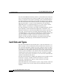
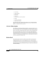
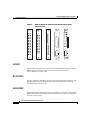
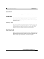
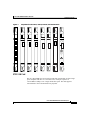
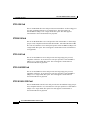
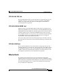
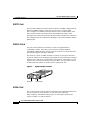
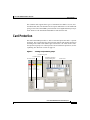
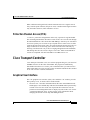
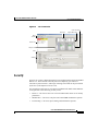
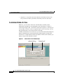
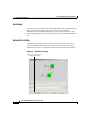
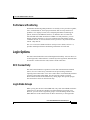
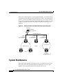
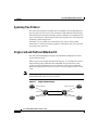
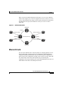
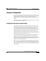
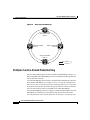
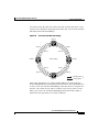
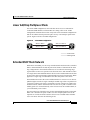
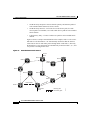
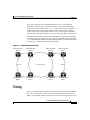
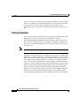
Cisco ONS 15454 SDH Product Overview
The Cisco ONS 15454 SDH provides efficient bandwidth delivery and
management in fiber-optic transport networks. It is a flexible, synchronous digital
hierarchy (SDH) add/drop multiplexer that offers service aggregation and
high-bandwidth transport of voice and data traffic on a single platform. The ONS
15454 SDH allows users to easily manage services and quickly increase capacity
without disrupting service. An ONS 15454 SDH is shown in Figure 1.
Figure 1
Cisco ONS 15454 SDH
Cisco ONS 15454 SDH Product Overview, R3.4
September 2002
1
Cisco ONS 15454 SDH Product Overview
Card Slots and Types
The ONS 15454 SDH shelf assembly contains 17 card (module) slots in the lower
shelf, 12 Front Mount Electrical Connection (FMEC) slots in the upper shelf, a
fan tray, a front panel with a liquid crystal display (LCD), and alarm indicators.
All card and electrical connections are accessible from the front of the chassis.
The ONS 15454 SDH carries traditional time-division multiplexing (TDM) and
high-speed data traffic. A variety of card configurations offer incremental
bandwidth increases as needed and support E-1, E-3, DS-3i, STM-1, STM-4,
STM-16, STM-64, 10/100 Ethernet, and Gigabit Ethernet speeds.
PCs and workstations can connect to the ONS 15454 SDH using direct, network
(LAN and WAN), or data communications channel (DCC) connections. Cisco
Transport Controller (CTC), the ONS 15454 SDH software interface, provides easy
card-, node-, and network-level provisioning and troubleshooting. The ONS
15454 SDH deploys a variety of network configurations, including point-to-point
1+1 linear multiplex-section protection systems, point-to-point 1+1 linear
add/drop multiplexers (ADMs), subnetwork connection protection rings
(SNCPs), two-fiber and four-fiber multiplex section-shared protection rings
(MS-SPRings), subtending rings, and extended SNCP mesh networks.
Card Slots and Types
The ONS 15454 SDH lower shelf assembly has 17 card slots numbered 1 to 17.
When you plug in a card, it automatically boots up and becomes ready for service.
The cards offer bandwidth in modular increments, making it efficient to deploy
the system in low-density applications and add bandwidth as needed. The ONS
15454 SDH lower shelf assembly houses four types of cards: common control,
electrical, optical, and Ethernet. The common control cards include the Timing
Communications and Control–International card (TCC-I) and the 10 Gigabit
Cross Connect card (XC10G). Slot number 9 is reserved for the Alarm Interface
Controller–International card (AIC-I).
The upper shelf assembly has 12 FMEC slots numbered 18 to 29. FMECs provide
serial ports, LAN ports, a modem connection for future use, electrical
connections, redundant power supplies, timing connections, and alarm
connections for the AIC-I card.
ONS 15454 SDH cards, when installed in a system, comply with IEC 60950, EN
60950, UL 60950, CSA C22.2 No. 60950, TS 001, and AS/NZS 3260 safety
standards.
Cisco ONS 15454 SDH Product Overview, R3.4
2
September 2002
Cisco ONS 15454 SDH Product Overview
Card Slots and Types
TCC-I Card
The TCC-I houses the central intelligence of the ONS 15454 SDH, including the
ONS 15454 SDH Operation, Administration, Maintenance and Provisioning
(OAM&P) software interface (CTC). The TCC-I card faceplate is shown in
Figure 2.
Figure 2
TCC-I card faceplate
TCC-I
FAIL
ACT/STBY
CRIT
MAJ
MIN
REM
SYNC
ACO
ACO
ASYNC
61207
LAN
As the main processing center of the ONS 15454 SDH, the TCC-I combines the
following timing, control, and switching functions:
•
System initialization
Cisco ONS 15454 SDH Product Overview, R3.4
September 2002
3
Cisco ONS 15454 SDH Product Overview
Card Slots and Types
•
Provisioning
•
Alarm reporting
•
Maintenance
•
Diagnostics
•
IP address detection and resolution
•
Timing
•
SDH DCC termination
•
System fault detection
The CRIT, MAJ, MIN, and REM alarm LEDs on the TCC-I faceplate indicate
whether a critical, major, minor, or remote alarm is present on the ONS 15454
SDH or on a remote node in the network.
In-Service Software Upgrade
The node name, configuration database, IP address, and system software (CTC)
are stored in the TCC-I card non-volatile memory, which allows quick recovery if
power or card failures occur. You can upgrade system software without affecting
traffic on the ONS 15454 SDH if dual TCC-I cards are used. The upgrade takes
place first on the standby TCC-I card. The system verifies that the upgrade is
successful and switches from the active TCC-I card running the older release to
the upgraded standby TCC-I card running the newer release. After the switch, the
second TCC-I card undergoes the upgrade. The TCC-I then loads new software to
each of the installed line (traffic) cards.
Database Revert
The increased memory of the TCC-I allows it to store and revert to the previous
configuration database. After a software upgrade, the TCC-I copies the current
working database and saves it in a reserved location in the TCC-I Flash memory. If
you later need to revert to the original working software load, the saved database will
activate automatically when you initiate the revert process. There is no need to restore
the database manually.
Cisco ONS 15454 SDH Product Overview, R3.4
4
September 2002
Cisco ONS 15454 SDH Product Overview
Card Slots and Types
XC10G Card
TheXC10G cross-connect card is the central switching element in the ONS 15454
SDH. You provision cross-connect (circuit) information using CTC; the TCC-I
then establishes the proper internal cross-connect information and relays the setup
information to the cross-connect card.
Note
For protection purposes, Cisco recommends duplex operation.
Duplex cross-connect cards must be the two XC10Gs.
The XC10G card cross-connects standard VC4, VC4-4c, VC4-16c and VC4-64c
signal rates and the non standard VC4-2c, VC4-3c, and VC4-8c signal rates
providing a maximum of 384 x 384 VC4 cross-connections. Any VC4 on any port
can be connected to any other port, meaning that the VC cross connection capacity
is nonblocking. The XC10G card manages up to 192 bidirectional VC4
cross-connects. The XC10G card faceplate is shown in Figure 3.
Cisco ONS 15454 SDH Product Overview, R3.4
September 2002
5
Cisco ONS 15454 SDH Product Overview
Card Slots and Types
Figure 3
XC10G card faceplate
XC10G
FAIL
68268
ACT/STBY
AIC-I Card
The optional AIC-I card provides customer-defined alarm input/output (I/O) and
supports user data and local and express orderwire. Figure 4 shows the AIC-I
faceplate and block diagram.
Cisco ONS 15454 SDH Product Overview, R3.4
6
September 2002
Cisco ONS 15454 SDH Product Overview
Card Slots and Types
Figure 4
AIC-I faceplate and block diagram
AIC-1
FAIL
PWR
A
B
ACT
Fail
Act
AIC-I
UDC-A
UDC-B
ACC
INPUT/OUTPUT
DCC-A
DCC-B
Express orderwire
ACC
(DTMF)
Ring
Local orderwire
12/16 x IN
(DTMF)
UDC-A
Ring
4x
IN/OUT
UDC-B
Ringer
DCC-A
Power
Monitoring
DCC-B
RING
LOW
Input
LED x2
AIC-I FPGA
Output
EOW
RING
EEPROM
78828
SCL links
Cisco ONS 15454 SDH Product Overview, R3.4
September 2002
7
Cisco ONS 15454 SDH Product Overview
Card Slots and Types
User-Defined Alarms
The AIC-I card provides input/output alarm contact closures. You can define up
to sixteen external alarm inputs and four external, user-configurable, alarm
inputs/outputs. The physical connections are made using the MIC-A/P. The
alarms are defined using CTC and TL1. LEDs on the front panel of the AIC-I
indicate the status of the alarm lines.
Orderwire
Orderwire allows a craftsperson to plug a phoneset into an ONS 15454 SDH and
communicate with craftspeople working at other ONS 15454 SDHs or other
facility equipment. The ONS 15454 SDH supports up to four orderwire channel
terminations per shelf. The orderwire ports are standard RJ-11 receptacles.
The AIC-I allows simultaneous use of both local (section overhead signal) and
express (line overhead channel) orderwire channels on a SONET/SDH ring or
particular optics facility. Express orderwire also allows communication via
regeneration sites when the regenerator is not a Cisco device. Orderwire is
provisioned from the CTC network view Provisioning > Overhead Circuits tabs.
User Data Channel
The user data channel (UDC) features four dedicated data channels. Each AIC-I
card supports the following UDCs:
•
Two F-UDCs, carried by the F1 byte of the regenerator section of the SDH
overhead. Each F-UDC provides a 64 KBit/s (kbps) point-to-point connection
between two nodes in an ONS 15454 SDH network. The F-UDCs are
connected to the AIC-I through two RJ-11 connectors on the front panel.
•
Two MS-UDCs, carried by the D4 to D12 bytes of the multiplex section of
the SDH overhead. The MS-UDC provides one 576 KBit/s (kbps)
point-to-point connection between two nodes in an ONS 15454 SDH
network. Each UDC can be routed to an individual and separate optical
interface on the ONS 15454 SDH system. The MS-UDCs are connected to the
AIC-I through RJ-45 connectors on the front panel.
All of the UDCs are provisioned from the CTC network view Provisioning >
Overhead Circuits tabs.
Cisco ONS 15454 SDH Product Overview, R3.4
8
September 2002
Cisco ONS 15454 SDH Product Overview
Card Slots and Types
Data Communication Channel
The data communications channel (DCC) features a dedicated data channel of 576
kBit/s (D4 to D12 bytes) between two nodes in an ONS 15454 SDH network.
Each AIC-I card provides two DCCs, DCC-A and DCC-B, through separate
RJ-45 connectors on the front of the AIC-I. Each DCC can be routed to an
individual optical interface in the ONS 15454 SDH system. DCC connection
cannot be provisioned if DCC tunneling is configured on this span.
FMECs
FMECs provide serial ports, LAN ports, a modem connection for future use,
electrical connections, redundant power supplies, timing connections, and alarm
connections for the AIC-I card. The upper shelf assembly has 12 FMEC slots
numbered 18 to 29. FMEC Slots 18 to 22 support the electrical cards in Slots
1 to 5 of the lower shelf. FMEC Slots 25 to 29 support the electrical cards in Slots
13 to 17 of the lower shelf. FMEC Slot 23 is used for the MIC-A/P alarm and
power card. FMEC Slot 24 supports the MIC-C/T/P timing, craft, and power card.
FMEC faceplates for the E1, E3/DS3, DS1/E1, MIC-A/P, and MIC-C/T/P cards
are shown in Figure 5.
Cisco ONS 15454 SDH Product Overview, R3.4
September 2002
9
Cisco ONS 15454 SDH Product Overview
Card Slots and Types
Figure 5
FMEC faceplates for the E1, E3/DS3, DS1/E1, MIC-A/P, and
MIC-C/T/P cards
FMEC
E1
FMEC
DS1/E1
MIC-C/T/P
MIC-A/P
FMEC
E3/DS3
TIMING A
TIMING B
1
Tx
ALARM
2
Rx
1
Tx
Rx
Tx
Rx
Tx
Rx
Tx
Rx
Tx
Rx
LAN
7
Tx
Rx
Tx
Rx
BARCODE
Tx
Rx
BARCODE
Tx
Tx
8
ACT
Tx
9
Tx
Tx
Tx
Tx
Tx
Tx
Tx
+
POWER RATING
Tx
Rx
10
Rx
11
Rx
12
Rx
POWER RATING
9
Rx
10
Rx
11
Rx
12
Rx
13
Rx
14
Rx
TERM
Tx
6
8
Rx
Tx
5
7
Rx
Tx
4
6
Rx
CLEI CODE
3
5
Rx
Tx
CLEI CODE
4
Rx
AUX
Tx
2
3
Rx
IN/OUT
+
Tx
BATTERY B
BATTERY A
78118
Rx
E1 FMEC
The E1 FMEC card allows the user to terminate unbalanced E1 interfaces. The E1
FMEC card provides front mount electrical connection for fourteen
ITU-compliant, G.703 E-1 ports.
DS1/E1 FMEC
The DS1/E1 FMEC card allows the user to terminate balanced E1 interfaces. The
DS1/E1 FMEC card provides front mount electrical connection for fourteen
ITU-compliant, G.703 E-1 ports.
E3/DS3 FMEC
The E3/DS3 FMEC card allows the user to terminate E3 interfaces. The E3/DS3
FMEC card provides front mount electrical connection for twelve ITU-compliant,
G.703 E-3 or DS-3 ports.
Cisco ONS 15454 SDH Product Overview, R3.4
10
September 2002
Cisco ONS 15454 SDH Product Overview
Card Slots and Types
BLANK FMEC
The BLANK card covers empty FMEC slots and fulfills EMC requirements.
MIC-A/P FMEC
The MIC-A/P FMEC card provides system power and alarm connections for the
TCC-I and AIC-I cards. The MIC-A/P card also stores manufacturing and
inventory data. For proper system operation, the MIC-A/P FMEC card must be
installed in the shelf.
MIC-C/T/P FMEC
The MIC-C/T/P FMEC card provides front-panel access for the Timing A and
Timing B connectors, two system power connectors at –48V, and two standard
eight-pin modular LAN connectors for each TCC-I card. For proper system
operation, the MIC-C/T/P FMEC card must be installed in the shelf.
Electrical Cards
Slots 1 to 5 and 13 to 17 host all electrical cards (E-1, E-3, and DS-3i). Each card
has faceplate LEDs showing active, standby, or alarm status. You can also obtain
the status of all electrical card ports using the LCD screen on the ONS 15454 SDH
fan-tray assembly. Figure 6 shows the E-1, E-3, and DS-3i faceplates.
Cisco ONS 15454 SDH Product Overview, R3.4
September 2002
11
Cisco ONS 15454 SDH Product Overview
Card Slots and Types
Figure 6
Faceplates for the E1-N-14, E3-12 and DS-3i cards
E1-N
14
DS3I- N
E3
12
12
FAIL
ACT/STBY
ACT/STBY
ACT/STBY
SF
SF
SF
33678 12931
33678 12931
33678 12931
78069
FAIL
FAIL
The upper shelf assembly has 12 FMEC slots numbered 18 to 22, and 25 to 29.
These slots support the electrical cards in Slots 1 to 5 and 13 to 17 of the lower
shelf. Each FMEC slot supports the electrical card in a specific slot of the lower
shelf. For example, FMEC Slot 18 supports only the electrical card in Slot 1 of
the lower shelf.
Note
Optical cards and Ethernet cards have connectors on the faceplate
rather than FMEC connections. E1000-2-G, and G1000-4 (Ethernet)
cards require Gigabit Interface Converters (GBICs) that plug into
the card faceplate.
Cisco ONS 15454 SDH Product Overview, R3.4
12
September 2002
Cisco ONS 15454 SDH Product Overview
Card Slots and Types
E1-N-14 Card
The E1-N-14 card provides fourteen ITU-compliant, G.703 E-1 ports. Each port
operates at 2.048 MBits/s (Mbps) over a 120-ohm twisted-pair copper cable with
the DS1/E1 FMEC, or over a 75-ohm unbalanced coaxial cable with the E1
FMEC.
The E1-N-14 card can be used as a working or protect card in 1:1 or 1:N
protection schemes. If you use the E1-N-14 as a standard E-1 card in a 1:1
protection group, you can install the E1-N-14 card in any multispeed or
high-speed card slot on the ONS 15454 SDH. To use the 1:N functionality of the
card, you must install an E1-N-14 card in Slot 3 or Slot 15.
E3-12 Card
The E3-12 card provides twelve ITU-compliant, G.703 E-3 ports per card. Each
port operates at 34.368 MBits/s (Mbps) over a 75-ohm coaxial cable with the
E3/DS3 FMEC. The E3-12 card can be used as a working or protect card in 1:1
protection schemes. When creating circuits, the E3 card must use port grouping
with VC low-order path tunnels. Three ports form one port group. For example,
in 1 E3 card, there are 4 port groups: Ports 1 to 3 = PG1, Ports 4 to 6 = PG2, Ports
7 to 9 = PG3, and Ports 10 to 12 = PG4.
DS-3i Card
The DS3i-N-12 card provides twelve DS-3 ports per card, compliant with ITU-T
G.703, Telcordia GR-499, and ITU-T G.704. Each port operates at 44.736
MBits/s (Mbps) over a 75-ohm coaxial cable with the E3/DS3 FMEC. The
twelve-port DS3i-N-12 card provides enhanced performance monitoring functions.
By monitoring additional overhead in the DS-3 frame, subtle network degradations
are detected. The DS3i-N-12 can operate as the protect card in a 1:N (N < 4) DS-3
protection group. It can protect up to four working DS3i-N-12 cards. When
creating circuits, the DS3i-N-12 card must use port grouping with VC low-order
path tunnels.
Cisco ONS 15454 SDH Product Overview, R3.4
September 2002
13
Cisco ONS 15454 SDH Product Overview
Card Slots and Types
Optical Cards
The optical cards, with the exception of the STM-64, reside in Slots 1 to 6 or
12 to 17. The STM-64 cards reside in Slot 5, 6, 12, or 13. You can provision an
optical card as a drop card or span card in a linear ADM (1+1), SNCP, or
MS-SPRing protection scheme.
Each card faceplate has three card-level LED indicators. When illuminated, the
red FAIL LED represents a hardware problem, the amber signal failure (SF) LED
represents a signal failure or condition (for example, a loss of frame or a high bit
error rate), and the green ACT LED indicates that the card is operational.
ONS 15454 SDH optical cards have SC fiber connectors on the card faceplate.
Figure 7 shows the STM-1, STM-4, STM-16 and STM-64 faceplates.
Cisco ONS 15454 SDH Product Overview, R3.4
14
September 2002
Cisco ONS 15454 SDH Product Overview
Card Slots and Types
Figure 7
Faceplates for the STM-1, STM-4, STM-16, and STM-64 cards
OC3IR4
STM1SH
1310
OC12IR
STM4SH
1310
OC12LR
STM4LH
1310
OC12LR
STM4LH
1550
OC48IR
OC48LR
OC48ELR
OC192LR
STM16SH
STM16LH
STM16EH
STM64LH
1310
1550
100GHz
1550
AS
AS
15XX.XX
FAIL
FAIL
FAIL
FAIL
FAIL
FAIL
FAIL
FAIL
ACT
ACT
ACT/STBY
ACT/STBY
ACT
ACT
ACT
ACT
SF
SF
SF
SF
SF
SF
SF
SF
0
Tx
1
Rx
1
TX
Tx
1
Tx
1
Tx
1
Rx
Rx
Rx
1
RX
TX
Tx
2
TX
TX
1
1
1
RX
RX
RX
Rx
TX
DANGER - INVISIBLE
LASER RADIATION
MAY BE EMITTED
FROM THE END OF
UNTERMINATED
FIBER CABLE OR
CONNECTOR. DO
NOT STARE INTO
BEAM OR VIEW
DIRECTLY WITH
OPTICAL
INSTRUMENTS.
Tx
3
Rx
RX
Tx
4
!
MAX INPUT
POWER LEVEL
- 10dBm
Rx
Class 1M (IEC)
33678 12931
33678 12931
33678 12931
33678 12931
33678 12931
33678 12931
78068
Class 1 (CDRH)
STM-1 SH Card
The OC3 IR 4/STM1 SH 1310 card provides four intermediate or short-range
ports compliant with ITU-T G.707 and G.957. Each port operates at
155.52 MBits/s (Mbps) over a single-mode fiber span. The card supports
concatenated or non-concatenated VC4 payloads.
Cisco ONS 15454 SDH Product Overview, R3.4
September 2002
15
Cisco ONS 15454 SDH Product Overview
Card Slots and Types
STM-4 SH Card
The OC12 IR/STM4 SH 1310 card provides one intermediate- or short-range port
per card, compliant with ITU-T G.707and G.957. The port operates at
622.08 MBits/s (Mbps) over a single-mode fiber span. The card supports
concatenated or non-concatenated VC4 payloads.
STM4-4 SH Card
The OC12 IR/STM4 SH 1310-4 card provides four intermediate- or short-range
port per card, compliant with Telcordia GR-253 IR-1, Telcordia GR-2918-CORE,
ITU-T G.707, and ITU-T G.957. Each port operates at 622.08 MBits/s (Mbps) over
a single-mode fiber span. The card supports concatenated or non-concatenated
VC4 payloads.
STM-4 LH Card
The OC12 LR/STM4 LH 1310 card provides one long-range port per card,
compliant with ITU-T G.707 and G.957. The port operates at 622.08 MBits/s
(Mbps) over a single-mode fiber span. The card supports concatenated or
non-concatenated VC4 payloads.
STM-4 LH 1550 Card
The OC12 LR/STM4 LH 1550 card provides one long-range port per card,
compliant with ITU-T G.707 and G.957. The port operates at 622.08 MBits/s
(Mbps) over a single-mode fiber span. The card supports concatenated or
non-concatenated VC4 payloads.
STM-16 SH AS 1310 Card
The OC48 IR/STM16 SH AS 1310 card provides one intermediate-range port per
card, compliant with ITU-T G.707 and G.957. The port operates at 2.488 GBits/s
(Gbps) over a single-mode fiber span. The card supports concatenated or
non-concatenated VC4 payloads.
Cisco ONS 15454 SDH Product Overview, R3.4
16
September 2002
Cisco ONS 15454 SDH Product Overview
Card Slots and Types
STM-16 LH AS 1550 Card
The OC48 IR/STM16 LH AS 1550 card provides one long-range port per card,
compliant with ITU-T G.707 and G.957. The port operates at 2.488 GBits/s
(Gbps) over a single-mode fiber span. The card supports concatenated or
non-concatenated VC4 payloads.
STM-16 EH 100 GHz DWDM Card
Eighteen distinct OC48 ELR/STM16 EH 100 GHz dense wavelength division
multiplexing (DWDM) cards provide the ONS 15454 SDH DWDM channel plan.
Although the ONS 15454 SDH uses 200-GHz spacing, these cards also work in
100-GHz-capable systems. Each STM-16 DWDM card provides one port per
card, compliant with ITU-T G.692, G.707, G.957, and G.958. The port operates
at 2.488 GBits/s (Gbps) over a single-mode fiber span. The card supports
concatenated or non-concatenated VC4 payloads.
Nine of the cards operate in the blue band with spacing of 100 GHz on the ITU
grid. The other nine cards operate in the red band with spacing of 100 GHz on the
ITU grid.
STM-64 LH 1550 Card
The OC192 LR/STM64 LH 1550 card provides one long-range port per card,
compliant with ITU-T G.707 and G.957. The port operates at 9.95 GBits/s (Gbps)
over unamplified distances of up to 80 km with different types of fiber such as
C-SMF or dispersion-compensated fiber limited by loss and/or dispersion. The
card supports concatenated or non-concatenated VC4 payloads.
Ethernet Cards
The Ethernet cards eliminate the need for external Ethernet aggregation
equipment and provide efficient transport and co-existence of traditional TDM
traffic with packet-switched data traffic. Multiple E-series Ethernet cards installed
in an ONS 15454 SDH can act as a single switch (EtherSwitch) supporting a
variety of SDH port configurations.
Cisco ONS 15454 SDH Product Overview, R3.4
September 2002
17
Cisco ONS 15454 SDH Product Overview
Card Slots and Types
E100T-G Card
The ONS 15454 SDH uses E100T-G cards for Ethernet 10 MBits/s (Mbps) and Fast
Ethernet 100 MBits/s (Mbps). Each card provides twelve switched, IEEE
802.3-compliant, 10/100BaseT Ethernet interfaces that can independently detect
(auto-sense) the speed of an attached device and automatically connect at the
appropriate speed. The ports determine whether to enable or disable flow control and
auto-configure to operate at either half or full duplex. You can also manually configure
Ethernet ports.
E1000-2-G Card
The ONS 15454 SDH uses the E1000-2-G cards for Gigabit Ethernet
1000 MBits/s (Mbps). Each card provides two ports of IEEE-compliant,
1000 MBits/s (Mbps) interfaces for high-capacity customer LAN interconnections.
Each interface supports full-duplex operation.
The E1000-2-G cards use GBIC modular receptacles for the optical interfaces
(Figure 8). GBICs are hot-swappable input/output devices that plug into a Gigabit
Ethernet port to link the port with the fiber-optic network. The E1000-2-G card
supports short-reach (SX) and long-reach (LX) GBICs. The SX model connects
to multimode fiber and the LX model requires single-mode fiber.
Gigabit Interface Converter
11825
Figure 8
Receiver
Transmitter
G1000-4 Card
The G-1000 is a high-capacity Ethernet card enhanced for high-bandwidth private
line interconnects. Like the E1000-2-G card, the G1000-4 provides
IEEE-compliant, 1000 MBits/s (Mbps) ports for full-duplex operation and
requires a GBIC as its optical interface.
Cisco ONS 15454 SDH Product Overview, R3.4
18
September 2002
Cisco ONS 15454 SDH Product Overview
Card Protection
The G1000-4 card supports three types of standard Cisco GBICs: SX, LX, and
extended reach (ZX). The G1000-4 has four ports rather than two. The additional
ports give the ONS 15454 SDH a practical limit of 40 Gigabit-Ethernet ports per
node. STM-16 is the maximum bandwidth on each G1000-4 card.
Card Protection
The ONS 15454 SDH provides 1:1 and 1:N electrical protection and 1+1 optical
protection. This section describes the protection options and explains protection
switching in the ONS 15454 SDH. Figure 9 shows the CTC tools used to create
card protection groups. For a description of E-series Ethernet protection, see the
“Spanning Tree Protocol” section on page 34.
Figure 9
Creating card protection groups
Provisioning tab
Create button
Create Protection
Group dialog box
Node view
71135
Protection tab
Cisco ONS 15454 SDH Product Overview, R3.4
September 2002
19
Cisco ONS 15454 SDH Product Overview
Card Protection
Electrical Protection
In 1:1 protection, a working card is paired with a protect card of the same type. If
the working card fails, the traffic from the working card switches to the protect
card. When the failure on the working card is resolved, by default traffic
automatically reverts to the working card.
1:N protection operates only at the E-1 and DS-3 levels. The 1:N protect cards
must be the same speed as their working cards. For example, an E1-N-14 card
protects E1-N-14 cards, and a DS3i-N-12 card protects DS3i-N-12 cards. Each
side of the shelf assembly has only one card that protects all of the cards on that
side.
Optical Protection
The ONS 15454 SDH supports 1+1 protection to create redundancy for optical
cards and spans. With 1+1 protection, one optical port can protect another optical
port; therefore, in any two high-speed slots a single working card and a single
dedicated protect card of the same type (for example, two STM-16 cards) can be
paired for protection. If the working port fails, the protect port takes over. 1+1
span protection can be either revertive or non-revertive.
Because the STM-1 card is a multiport card, port-to-port protection is available.
The ports on the protect card support the corresponding ports on the working card.
Protection Switching
The ONS 15454 SDH supports revertive and non-revertive, unidirectional or
bidirectional switching for optical signals. 1:N electrical protection is always
revertive and bidirectional; 1:1 electrical protection is also bidirectional but
provides the revertive or non-revertive option.
When a failure occurs and automatic protection switching (APS) switches the
signal from the working card to the protect card, revertive switching automatically
switches the signal back to the working card after the provisionable revertive time
period has elapsed. With non-revertive switching, traffic does not automatically
revert to the working card when the working card reverts to active status.
Cisco ONS 15454 SDH Product Overview, R3.4
20
September 2002
Cisco ONS 15454 SDH Product Overview
Cisco Transport Controller
When a bidirectional signal fails, both the transmit and receive signals switch
away from the point of failure (the port or card). A unidirectional signal switches
only the failure direction, either transmit or receive.
Protection Channel Access (PCA)
1:1 and 1+1 protection configurations utilize only a portion of ring bandwidth.
The remaining bandwidth is idle until a switch occurs. PCA circuits run through
the idle bandwidth on 2-fiber and 4-fiber MS-SPRings. Since they are considered
to be lower priority, PCA circuits are pre-empted when a switch occurs to make
room for the protected circuits. They are restored when the protected circuit is no
longer needed. PCA circuits help you to utilize networks more efficiently by
lowering overall network cost per bit, leveraging untapped network bandwidth,
and sharing network costs across a larger service base. ONS 15454 SDH PCA
circuits are compliant with Telcordia GR-1230-CORE Section 3.4.
Cisco Transport Controller
Cisco Transport Controller (CTC) is a software program that gives you control of
OAM&P activities for the ONS 15454 SDH. The program is automatically
downloaded from the TCC-I card to your workstation when you connect to the
ONS 15454 SDH. CTC also provides a setup wizard that installs the files needed
to use CTC on a PC or Solaris workstation.
Graphical User Interface
The CTC graphical user interface (GUI), also called the CTC window, provides
three primary views, or modes. These modes include:
•
Network view—Provides information about the ONS 15454 SDH network
and displays a user-defined map with ONS 15454 SDH nodes represented by
colored icons. The color of the icon represents the node status. You can
perform network management tasks or display any node in this view. See the
“Customized Network View” section on page 24 for information about
changing the default network map and adding domains.
Cisco ONS 15454 SDH Product Overview, R3.4
September 2002
21
Cisco ONS 15454 SDH Product Overview
Cisco Transport Controller
•
Node view—Provides information about the node and displays a graphic of
the ONS 15454 SDH shelf (Figure 10 on page 23). The cards are color-coded
to show the status of the physical cards and ports. This is the default view
displayed each time you log into CTC. You can perform node management
tasks in this view. Figure 10 shows the CTC software in node view.
•
Card view—Provides information about individual ONS 15454 SDH cards
and displays a graphic of the selected card. The information that appears and
the tasks you can perform depend on the card. You can perform card and
port-specific maintenance tasks in this view.
The CTC GUI displays tabs and subtabs. From the tabs you can perform all of the
OAM&P tasks. These tasks include provisioning cards, circuits, and rings; creating
protection groups; setting timing parameters; viewing and clearing alarms;
provisioning DCCs; backing up and restoring the database; and troubleshooting,
including creating diagnostic files and performing loopbacks.
You can filter the display of circuits in any of the CTC views. Circuits can be filtered
by name, direction, circuit status (active, incomplete, or upgradable), slot, port, type
(high-order circuit, low-order circuit, or low-order tunnel), or size. You can also view
the circuits that belong to a particular span.
Note
The FMECs in the upper shelf cannot be preprovisioned.
Cisco ONS 15454 SDH Product Overview, R3.4
22
September 2002
Cisco ONS 15454 SDH Product Overview
Cisco Transport Controller
Figure 10
CTC in node view
Lower card shelf
Node view
Upper FMEC shelf
Menu
Tool bar
Status area
Graphic area
Tabs
71129
Subtabs
Security
Several CTC security enhancements have been implemented in ONS 15454 SDH
Release 3.4. These include enforced password complexity, prevention of
consecutive password reuse, and a login warning screen that can be provisioned
by the user (with Superuser access level).
You can add up to 500 users to one ONS 15454 SDH. Each ONS 15454 SDH user
is assigned one of the following security levels:
•
Retrieve—Can retrieve and view CTC information but cannot set or modify
parameters.
•
Maintenance—Can access only the ONS 15454 SDH maintenance options.
•
Provisioning—Can access provisioning and maintenance options.
Cisco ONS 15454 SDH Product Overview, R3.4
September 2002
23
Cisco ONS 15454 SDH Product Overview
Cisco Transport Controller
•
Superusers—Can perform all of the functions of the other security levels.
They can also set names, passwords, and security levels for other users.
Customized Network View
With CTC, you can choose from a list of default maps (Germany, Japan,
Netherlands, South Korea, United Kingdom, and United States) or import a
custom map using the Edit > Preferences menu option (Figure 11). The map can
be any image you choose, such as a regional map or even a street map. You can
drag and drop nodes to move their location on the map.
To further customize the CTC network view, you can create domains that manage the
display of multiple nodes on the network map. Domains appear as clouds on the
network view. A single domain can have any number of nodes. From a domain, you
display or log into any node that it contains.
Figure 11
Choose from a list of default maps
Choose from a list
of default maps
71118
Enter or browse to
custom map or image
Cisco ONS 15454 SDH Product Overview, R3.4
24
September 2002
Cisco ONS 15454 SDH Product Overview
Cisco Transport Controller
Circuit Provisioning and Management
CTC enables automated circuit provisioning across ONS 15454 SDH networks
and between ONS 15454 SDHs, including VC4 high-order path circuits and VC
low-order path tunnels, as well as multiple drop and monitor circuits. From the CTC
GUI, select a source and destination ONS 15454 SDH to create an end-to-end
circuit. You can also create a half circuit, from a drop to an STM-N card on the
same node.
CTC automatically calculates a circuit path between the source and destination.
You select the circuit type, circuit size, bidirectional or unidirectional status, and
path-protection or protected drops restrictions. You can also route high-order path
circuits manually, for example, to force traffic onto a particular path. Figure 12
shows the CTC tools used to create circuits. See the “Ethernet Circuits” section
on page 35 for a description of Ethernet circuits.
Figure 12
Creating circuits with the CTC Circuit Creation dialog box
Circuits tab
Circuit Creation
dialog box
Circuits can be created from
network, node, or card view
71556
Create button
Cisco ONS 15454 SDH Product Overview, R3.4
September 2002
25
Cisco ONS 15454 SDH Product Overview
Cisco Transport Controller
Auto Range
CTC provides an auto-range feature that automatically creates sequential circuits
Specify the number of circuits you need, create one circuit, and CTC
automatically creates additional sequential circuits. This feature allows you to
create multiple circuits of the same type without having to individually build each
one.
Detailed Circuit Map
The detailed circuit map (Figure 13) allows you to see an end-to-end view of
circuits, including ports, drops, spans, and selectors for SNCP circuits. This
differs from the node view, which shows nodes and spans but no circuit details.
Figure 13
Detailed circuit map
71714
From nodeview, choose Circuits,
Edit, Show Detailed Map
Cisco ONS 15454 SDH Product Overview, R3.4
26
September 2002
Cisco ONS 15454 SDH Product Overview
Login Options
Performance Monitoring
Performance monitoring (PM) parameters are used by service providers to gather,
store, set thresholds for, and report performance data for early detection of
problems. CTC displays section, line, and path performance monitoring for
optical, electrical, and Ethernet statistics, as defined in ITU-T G.826 and
Telcordia GR-820-CORE and GR-253-CORE. For each parameter, you can
display statistics about the 31 previous 15-minute intervals and the current
15-minute interval, as well as statistics for the previous 1-day interval and the
current 1-day interval.
The Cisco ONS 15454 SDH Installation and Operations Guide, Release 3.4,
provides detailed performance monitoring information for each card.
Login Options
The ONS 15454 SDH offers network management flexibility. You can choose to
see the login node, nodes with DCC-connectivity to the login node, and nodes that
are not DCC-connected to the node, but have an IP connection.
DCC Connectivity
The ONS 15454 SDH uses regenerator section data communication channels
(DCCs) for CTC connectivity, automated circuit provisioning, and alarm
reporting from remote nodes. CTC uses a node’s SDCC to automatically find and
recognize other ONS 15454 SDHs. You also have the option to exclude
DCC-connected nodes from autodiscovery during login. This speeds up login
time and reduces clutter on the network map.
Login Node Groups
When you log into an ONS 15454 SDH node, only ONS 15454 SDHs with DCC
connectivity to the node are autodiscovered and displayed in network view.
However, you can create a login node group to view and manage ONS 15454
SDHs that have an IP connection but no DCC connectivity to the login node.
Cisco ONS 15454 SDH Product Overview, R3.4
September 2002
27
Cisco ONS 15454 SDH Product Overview
System Maintenance
Refer to the example in Figure 14. If you logged into Node 1, you would see Node
2 and Node 3 because they have DCC connectivity to Node 1. You would not see
Nodes 4, 5, and 6 because DCC connections do not exist. To view all six nodes at
once, create a login node group that contains the IP addresses of Nodes 1, 4, and
5. When you log into any node in the group, all optically connected nodes are
displayed.
Figure 14
Viewing non-DCC-connected nodes using a login node group
Laptop PC
IP Address
192.168.106.100
LAN/WAN (Ethernet)
Node 1
IP Address
192.168.106.143
Node 4
IP Address
192.168.105.119
Node 5
IP Address
192.168.104.109
Two node ring
Node 2
Single
Node 3
Node 6
IP Address
192.168.103.199
55029
Three node ring
System Maintenance
ONS 15454 SDH equipment can be placed in one of four different service states.
These states make the equipment available for maintenance or service. Span
upgrades can be performed without removing cards from service.
Cisco ONS 15454 SDH Product Overview, R3.4
28
September 2002
Cisco ONS 15454 SDH Product Overview
In-Service Span Upgrades
Service States
ONS 15454 SDH cards, ports, and circuits can be placed in any of the following
service states:
•
In Service (IS)—The card, port, or circuit is fully available for operation
(working or protect).
•
Out of Service (OOS)—The card, port, or circuit is not available for
operation.
•
Out of Service for Maintenance (OOS-MT)—The port or circuit has been
temporarily taken out of service for maintenance. Alarms are not reported
autonomously, but they can be retrieved. This state is not available for cards.
•
Out of Service—Auto In Service (OOS-AINS)—The card, port, or circuit is
currently out of service, but will automatically be placed in service when a
valid card is plugged into the preprovisioned slot and fully initialized.
Use the CTC Provisioning >Line tabs or the CTC Maintenance > Line tabs to
transition ports from state to state. The user can also transition the port into
different states from the State tab in the Edit Circuit window.
In-Service Span Upgrades
A span is the optical-fiber connection between two ONS 15454 SDH nodes. In a
span upgrade, the transmission rate of a span is upgraded from a lower to a higher
STM-N signal. All other span configuration attributes remain unchanged. With
multiple nodes, a span upgrade is a coordinated series of upgrades on all nodes in
the ring or protection group. You can perform in-service span upgrades for the
following ONS 15454 SDH cards:
•
STM-4 to STM-16
•
STM-4 to STM-64
•
STM-16 to STM-64
To perform a span upgrade, the higher-rate optical card must replace the
lower-rate card in the same slot. The protection configuration of the original
lower-rate optical card (two-fiber MS-SPRing, four-fiber MS-SPRing, SNCP, or
1+1) is retained by the higher-rate optical card. The Span Upgrade Wizard
automates the span upgrade procedure for all protection configurations.
Cisco ONS 15454 SDH Product Overview, R3.4
September 2002
29
Cisco ONS 15454 SDH Product Overview
Alarm Collection and Display
Alarm Collection and Display
The ONS 15454 SDH has several methods to alert you to possible problems with
the node. The ONS 15454 SDH faceplate has LEDs that alert you to critical,
major, minor, and remote alarms on the node. The LCD provides alarm
information on a port and card level in addition to node level. CTC displays
alarms and events on a port, card, or node level for all nodes in the network. CTC
can also highlight the circuits that are affected by a particular alarm.
Front Panel LEDs
The critical, major and minor alarm LEDs on the fan-tray front panel indicate
whether a critical, major, or minor alarm is present anywhere on the ONS 15454
SDH assembly. These LEDs are viewable through the front door so that you can
quickly determine if any alarms are present on the assembly. These LEDs are
independent of the Slot, Status, and Port indicators on the LCD.
LCD Alarm Indicators
The ONS 15454 SDH LCD screen (Figure 15) provides slot- and port-level alarm
information for all ONS 15454 SDH card slots, including the number of critical,
major, and minor alarms.
Using the LCD
Slot
Status
Port
06/29/01
24˚C
03.00-001A-00
FAN FAIL CRIT
MAJ
MIN
Cisco ONS 15454 SDH Product Overview, R3.4
30
September 2002
34192
Figure 15
Cisco ONS 15454 SDH Product Overview
Alarm Collection and Display
CTC Display
Alarms (cleared or active), conditions, and events are displayed in one of five
background colors to quickly communicate the alarm severity. You can control the
display of current and cleared alarms generated on the node. Information displayed
includes the date, time, severity, reporting node, reporting object,
service-affecting status, and description of the alarm or event (Figure 16).
Figure 16
Viewing alarms for the current session
Node view
78119
History tab
CTC displays historical alarm data and shows events (non-alarmed occurrences)
such as performance monitoring threshold crossings or protection switching
events. CTC presents the following two alarm history views:
•
Session subtab—Presents alarm and event messages for the current CTC
session. When you log off, the alarm list generated during the CTC session
disappears.
Cisco ONS 15454 SDH Product Overview, R3.4
September 2002
31
Cisco ONS 15454 SDH Product Overview
Alarm Collection and Display
•
Node subtab—Shows alarm and event messages that occurred at the node
since the CTC software installation, and also alarm and event messages for
the current CTC session. The ONS 15454 SDH can store up to 640 critical
alarm raise/clear messages, 640 major alarm raise/clear messages, 640 minor
alarm raise/clear messages, and 640 events. When the limit is reached for a
category, the ONS 15454 SDH discards the oldest alarms and event-level
raise/clear/transient messages in that category.
Alarm Profiles
The ONS 15454 SDH includes an alarm profile feature, accessible from the CTC
network view. This feature allows you to change the default alarm severities (for
example, from minor to major) and apply the new severities at the card, port, or
node level. Alarm profiles for a given card can be viewed in the Alarm Behavior
tab in the CTC card view.
CTC also has a network element (NE) default feature that allows you to change
port and card level default settings for the ONS 15454 SDH from one convenient
location. This feature can be accessed from the Provisioning > Defaults Editor
tabs in the node view.
In addition to user-defined profiles, CTC stores a default profile that sets severities
to standard ITU-T G.783 settings. To create a new profile, clone the default in
CTC, rename it, and choose the severity settings for the new profile.
Alarm Suppression
From the card view, you can suppress alarms on specific ports. From the node
view, you can suppress alarms on specific cards or on the entire node.
If alarms are suppressed, they do not appear on the CTC Alarm screen. On the
History screen, a message states that the alarms are suppressed, and the
Conditions tab shows the suppressed alarms. The node sends out autonomous
messages to clear any raised alarms. When alarm suppression is turned off, the
node sends out autonomous messages to raise any suppressed alarms that are still
active.
Cisco ONS 15454 SDH Product Overview, R3.4
32
September 2002
Cisco ONS 15454 SDH Product Overview
Ethernet
Ethernet
The ONS 15454 SDH integrates Ethernet access into the same SDH platform that
transports voice traffic. Service providers use Ethernet over SDH to augment
TDM services while delivering data traffic over existing facilities. The ONS
15454 SDH supports Layer 2 switching and the ability to classify Ethernet traffic
as defined in the IEEE 802.1 Q-tag standard. You can switch tagged traffic onto
separate SDH VC4 channels to engineer bandwidth by traffic class. The ONS
15454 SDH can also concentrate Ethernet ports into one or more VC4 circuits to
use bandwidth more efficiently.
Note
The E-series cards (E100T-G, E1000-2-G) support Layer 2
switching, but the G-series card (G1000-4) does not.
Priority Queuing
Networks without priority queuing handle all packets on a first-in, first-out
(FIFO) basis. Priority queuing, which is supported by the ONS 15454 SDH,
reduces the impact of network congestion by mapping Ethernet traffic to different
priority levels. The ONS 15454 SDH takes the eight priorities specified in IEEE
802.1Q and maps them to two queues. Q-tags carry priority queuing information
through the network.
VLAN Service
The ONS 15454 SDH works with Ethernet devices whether they support IEEE
802.1Q tagging or not. The ONS 15454 SDH supports virtual LANs (VLANs)
that provide private network service across an SDH backbone. You can define
specific Ethernet ports and SDH VC4 channels as a VLAN group. VLAN groups
isolate subscriber traffic from users outside the VLAN group and keep external
traffic from “leaking” into the virtual private network (VPN). Each IEEE 802.1Q
VLAN represents a different logical network.
Cisco ONS 15454 SDH Product Overview, R3.4
September 2002
33
Cisco ONS 15454 SDH Product Overview
Ethernet
Spanning Tree Protocol
The ONS 15454 SDH uses the IEEE 802.1D standard to provide Spanning Tree
Protocol (STP) on the E-series cards. STP detects and eliminates network loops
both internally and externally. Internally, it detects multiple circuit paths between
any two network ports and blocks ports until only one path exists. The single path
eliminates possible bridge loops.
Externally, you can enable STP at the Ethernet port level to allow parallel
connections to external networking equipment. STP allows only one connection
to be used at any given time.
Single-Card and Multicard EtherSwitch
The ONS 15454 SDH supports Single-card and Multicard EtherSwitch on the
E-series Ethernet cards.
When you provision a Single-card EtherSwitch (Figure 17), each Ethernet card is a
single switching entity within the ONS 15454 SDH. This option allows a full
VC4-4c worth of bandwidth between two Ethernet circuit points. Single-card
EtherSwitch supports one VC4-4c, two VC4-2c, one VC4-2c plus two VC4s, or four
VC4s.
Note
When configuring one VC4-2c plus two VC4s, the VC4-2c must be
provisioned before either of the VC4 circuits.
Figure 17
Single-card EtherSwitch
Ethernet card #1
Ethernet card #2
Router
Router
ONS Node
VLAN A
ONS Node
VLAN B
Router
Ethernet card #4
45132
Ethernet card #3
Router
Cisco ONS 15454 SDH Product Overview, R3.4
34
September 2002
Cisco ONS 15454 SDH Product Overview
Ethernet
When you provision Multicard EtherSwitch (Figure 18), two or more Ethernet
cards act as a single Layer 2 switch. It supports one VC4-2c circuit or two VC4
circuits. The bandwidth of the single switch formed by the Ethernet cards matches
the bandwidth of the provisioned Ethernet circuit up to VC4-2c worth of
bandwidth.
Figure 18
Multicard EtherSwitch
ONS Node
VLAN A
Ethernet card #1
Ethernet card #2
Router
Router
Shared packet ring
Ethernet card #3
ONS Node
Ethernet card #4
Router
45133
ONS Node
Router
ONS Node
Ethernet Circuits
The ONS 15454 SDH has three common methods for configuring Ethernet circuits
between ONS nodes: a point-to-point circuit configuration, a shared packet ring
configuration (Multicard EtherSwitch only), and a hub-and-spoke configuration. A
point-to-point circuit configuration is usually used to connect two nodes. More than
two nodes usually connect with a shared packet ring or a hub-and-spoke
configuration. You can also manually cross connect individual Ethernet circuits to an
STM channel on the ONS 15454 SDH optical interface.
Cisco ONS 15454 SDH Product Overview, R3.4
September 2002
35
Cisco ONS 15454 SDH Product Overview
Network Management
Network Management
The ONS 15454 SDH is compatible with several network management protocols,
such as Simple Network Management Protocol (SNMP), Proxy Address
Resolution Protocol (ARP), Open Shortest Path First (OSPF) protocol, and
Routing Information Protocol (RIP). If OSPF is not available, static routes can
also connect to ONS 15454 SDHs through routers. DCC tunneling is provided for
interoperability with other vendors’ equipment.
Simple Network Management Protocol
SNMP is an application-layer Internet Protocol (IP) that enables network devices
to exchange management information. Network administrators can manage
network performance, find and solve network problems, and plan for network
growth. The ONS 15454 SDH supports SNMP Version 1 (SNMPv1) and SNMP
Version 2c (SNMPv2c). SNMPv2c offers additional protocol operations.
The ONS 15454 SDH uses SNMP to communicate segments of the CTC information
model to network management systems, such as the Hewlitt-Packard OpenView
Network Node Manager (NNM) or Open Systems Interconnection (OSI) NetExpert.
SNMP conveys information required for node-level inventory, fault, and performance
management of the ONS 15454 SDH node, and for generic read-only management of
E-1, E-3, SDH, and Ethernet.
The ONS 15454 SDH incorporates SNMP remote monitoring (RMON) to allow
network operators to monitor the ONS 15454 SDH Ethernet cards. RMON
operates transparently with a network management application, but you can
provision RMON alarm thresholds with CTC.
Proxy ARP
Proxy ARP enables a LAN-connected gateway ONS 15454 SDH to automatically
handle ARP requests for remote non-LAN ONS 15454 SDHs connected by a DCC
to the gateway ONS 15454 SDH. Proxy ARP requires no manual configuration in
CTC.
Proxy ARP has a single LAN-connected ONS 15454 SDH stand-in (proxy) for
remote ONS 15454 SDHs. If a device on the LAN sends an ARP request intended for
one of the DCC-connected ONS 15454 SDHs, the gateway ONS 15454 SDH returns
Cisco ONS 15454 SDH Product Overview, R3.4
36
September 2002
Cisco ONS 15454 SDH Product Overview
Network Management
its own MAC address to the LAN device. The LAN device then sends the datagram
intended for the remote ONS 15454 SDH to the MAC address of the proxy ONS
15454 SDH. The proxy ONS 15454 SDH forwards this data to the remote 15454 SDH
using its own ARP table.
Open Shortest Path First
If ONS 15454 SDHs are connected to OSPF networks, ONS 15454 SDH network
information can be automatically communicated across multiple LANs and
WANs. Use CTC to view and configure OSPF area information for the nodes that
the OSPF network controls.
OSPF is a link state Internet routing protocol. Link state protocols use a “hello
protocol” to monitor their links with adjacent routers and test their links to their
neighbors. Link state protocols advertise their directly connected networks and
their active links. Each link state router captures the link state advertisements and
puts them together to create a topology of the entire network or area. From this
database, the router calculates a routing table by constructing a shortest path tree.
Routes are continuously recalculated to capture ongoing topology changes.
You can enable OSPF on the ONS 15454 SDHs so that the ONS 15454 SDH
topology is sent to OSPF routers on a LAN. Advertising the ONS 15454 SDH
network topology to LAN routers eliminates the need to manually provision static
routes for ONS 15454 SDH subnetworks.
Proxy Server Feature
The ONS 15454 proxy server is a set of functions that allows you to network ONS
15454 SDHs in environments where visibility and accessibility between ONS
15454s and CTC computers must be restricted. For example, you can set up a
network so that field technicians and network operations center (NOC) personnel
can both access the same ONS 15454 SDHs while preventing the field technicians
from accessing the NOC LAN. To do this, one ONS 15454 SDH is provisioned as
a gateway NE (GNE) and the other ONS 15454 SDHs are provisioned as end NEs
(ENEs). The GNE ONS 15454 SDH tunnels connections between CTC computers
and ENE ONS 15454 SDHs, providing management capability while preventing
access for non-ONS 15454 SDH management purposes.
Cisco ONS 15454 SDH Product Overview, R3.4
September 2002
37
Cisco ONS 15454 SDH Product Overview
Network Management
Routing Information Protocol
RIP is an interior gateway protocol, which means that it performs routing within
a single autonomous system. It is widely used to route traffic in the global
Internet.
RIP routers maintain only the best route (the route with the lowest metric value)
to a destination. After updating its routing table, the router immediately begins
transmitting routing updates to inform other network routers of the change. These
updates are sent independently of the regularly scheduled updates that RIP routers
send.
Static Route Provisioning
The ONS 15454 SDH uses CTC to provision static network routes. Static routes
allow workstations to connect to ONS 15454 SDHs through routers. Static routes
also make it possible to have multiple CTC sessions with different destination IP
addresses on a network of ONS 15454 SDHs that are all on the same subnet. For
example, a NOC can remotely monitor an ONS 15454 SDH through CTC while
an onsite employee is logged into a network ONS 15454 SDH through a separate
CTC session. If OSPF is connected and running, static routes are unnecessary.
DCC Tunneling
You can tunnel third-party SDH equipment DCCs across ONS 15454 SDH networks.
A DCC tunnel is a series of connection points that map a third-party equipment DCC
to ONS 15454 SDH DCCs. A DCC tunnel endpoint is defined by the slot, port, and
DCC type. To create a DCC tunnel, connect the tunnel endpoints from one ONS
15454 SDH optical port to another. DCC traffic is forwarded transparently,
byte-for-byte, across the ONS 15454 SDH network.
Cisco ONS 15454 SDH Product Overview, R3.4
38
September 2002
Cisco ONS 15454 SDH Product Overview
Network Configuration
Network Configuration
The ONS 15454 SDH supports subnetwork connection protection (SNCP) rings,
multiplex section-shared protection rings (MS-SPRings), subtending rings, linear
add/drop multiplexers (ADMs) that support 1+1 protection, and mixed
configurations. You can also create extended SNCP mesh networks (extended
SNCP).
Circuit protection can be configured in CTC. You can also use CTC to specify the
nodes and spans to use for the protect path.
Subnetwork Connection Protection Ring
The default protection scheme for an ONS 15454 SDH is the SNCP ring. An
SNCP ring is a closed-loop, two-fiber transport architecture that survives cable
cuts and equipment failure because it provides duplicate fiber paths for each
service. Nodes in the ring are connected using a single pair of optical fibers.
Working traffic flows in one direction on the ring and the second fiber provides a
protection path flowing in the opposite direction. If a problem occurs in the
working traffic path, the receiving node switches to the path coming from the
opposite direction. SNCP signal thresholds—the levels that determine when the
SNCP path is switched—are set at the circuit level.
Services can originate and terminate on the same SNCP or can be passed to an
adjacent access or interoffice ring for transport to the service-terminating
location. You can also create an SNCP bridge/selector circuit entry point in a
multivendor SNCP. Because each traffic path is transported around the entire ring,
SNCPs are best suited for networks where traffic concentrates in one or two
locations and is not widely distributed.
Figure 19 shows a basic SNCP ring configuration. If Node A sends a signal to
Node C, the working signal travels on the working traffic path through Node B.
The same signal is also sent on the protect traffic path through Node D. If a fiber
break occurs, Node C switches its active receiver to the protect signal coming
through Node D.
Cisco ONS 15454 SDH Product Overview, R3.4
September 2002
39
Cisco ONS 15454 SDH Product Overview
Network Configuration
Figure 19
Basic four-node SNCP ring
ONS 15454 SDH
Node A
ONS 15454 SDH
Node D
ONS 15454 SDH
Node B
= Fiber 1
= Fiber 2
71267
ONS 15454 SDH
Node C
Multiplex Section–Shared Protection Ring
The ONS 15454 SDH supports two-fiber and four-fiber MS-SPRings with up to 16
ONS 15454 SDH nodes. MS-SPRings work well for distributed traffic applications,
such as interoffice networks.
Two-fiber MS-SPRings allocate half the available fiber bandwidth for protection.
In an STM-16 MS-SPRing, for example, VC4s 1 to 8 carry the working traffic,
and VC4s 9 to 16 are reserved for protection. Working traffic (VC4s 1 to 8) travels
in one direction on the first fiber and in the opposite direction on the second fiber.
You can create STM-4, STM-16, and STM-64 two-fiber MS-SPRings.
Four-fiber MS-SPRings (Figure 20 on page 41) double the bandwidth of two-fiber
MS-SPRings by dedicating a second optical card for protection rather than
reserving half of the active card for protection. If one fiber is cut, the ring does
Cisco ONS 15454 SDH Product Overview, R3.4
40
September 2002
Cisco ONS 15454 SDH Product Overview
Network Configuration
not switch because the other fiber carries the traffic for the broken span. A ring
switch occurs if both the working and protect fibers fail. You can create STM-16
and STM-64 four-fiber MS-SPRings.
Figure 20
Four-node, four-fiber MS-SPRing
Node 0
Span 4
Span 1
Span 5
Span 8
STM-16 Ring
Span 6
Node 1
Span 7
Span 3
Span 2
= Working fibers
Node 2
= Protect fibers
71275
Node 3
ONS 15454 SDH Release 3.4 contains an MS-SPRing Provisioning Wizard,
accessed through the Provisioning tab in the network view. The wizard allows you
to easily create, edit, and delete MS-SPRings at the network level, using the CTC
interface. The wizard not only reduces common errors in ring creation, it also
helps you to create, edt, and delete MS-SPRings much faster than it takes to
perform the same operations on a node-by-node basis.
Cisco ONS 15454 SDH Product Overview, R3.4
September 2002
41
Cisco ONS 15454 SDH Product Overview
Network Configuration
Subtending Rings
The ONS 15454 SDH supports up to ten SDH DCCs. Therefore, one ONS 15454
SDH node can terminate and groom any ring combination as long as the total DCC
usage is equal to or less than 10 DCCs.
Subtending rings from a ONS 15454 SDH reduces the number of nodes and cards
required, and reduces external shelf-to-shelf cabling. Figure 21 shows an ONS
15454 SDH with multiple subtending rings. In this example, Node 3 is the only
node serving both the MS-SPRing and SNCP ring. Optical cards in Slots 5 and 12
serve the MS-SPRing, and optical cards in Slots 6 and 13 serve the SNCP.
Figure 21
ONS 15454 SDH with multiple subtending rings
SNCP
SNCP
SNCP
or MS-SPRing
SNCP
71273
SNCP
or
MS-SPRing
Cisco ONS 15454 SDH Product Overview, R3.4
42
September 2002
Cisco ONS 15454 SDH Product Overview
Network Configuration
Linear Add/Drop Multiplexer Mode
In a linear ADM configuration, each node has direct access to eastbound or
westbound STM channels at intermediate sites along a fiber route. ADM
configurations eliminate the need for costly back-to-back terminal configurations
and can be enhanced with protection spans for any or all transport spans in the
system. Figure 22 shows an ADM configuration.
Linear ADM configuration
Slot 6 to Slot 6
Slot 12 to Slot 12
Slot 5 to Slot 5
Slot 13 to Slot 13
Node 1
61022
Figure 22
Node 2
Node 3
Protect Path
Working Path
Extended SNCP Mesh Network
With ONS 15454 SDH, you can set up extended SNCP mesh networks (extended
SNCP). Extended SNCP extends the protection scheme of SNCP from the basic
ring configuration to the meshed architecture of several interconnecting rings.
Typical SNCP creates two separate routes between source and destination nodes
on a single SNCP. Extended SNCP does this for source and destination nodes that
are not on the same ring but link together through a network of connections. When
applied to a single ring, extended SNCP uses the same paths as the SNCP.
Extended SNCP connects the source and destination of a circuit over two diverse
paths through a network of single or multiple meshed rings. These two paths form
a circuit-level SNCP. The source sends traffic on each of the diverse paths to the
destination node, and the destination node uses the active path or switches to the
standby path. CTC can automatically route circuits across the extended SNCP, or
you can manually route circuits.
You can set the level of node diversity for the extended SNCP portions of the path.
When CTC calculates the path, it makes sure the computed path traverses the
required set of nodes and links and does not traverse excluded nodes and links.
Users can choose between the following levels:
Cisco ONS 15454 SDH Product Overview, R3.4
September 2002
43
Cisco ONS 15454 SDH Product Overview
Network Configuration
•
Nodal Diversity Required—Ensures that the primary and alternate paths of
each extended SNCP domain use diverse nodes.
•
Nodal Diversity Desired—CTC looks for a node diverse path; if a node
diverse path is not available, CTC finds a link diverse path for each extended
SNCP domain.
•
Link Diversity Only—Creates a link diverse path for each extended SNCP
domain.
Figure 23 shows a sample extended SNCP. In the example, Node 3 is the source
and Node 9 is the destination. CTC automatically determines that the shortest
route between the two end nodes passes through Node 8 and Node 7, shown by
the dotted line. Cross-connections are automatically created at Nodes 3, 8, 7, and
9 to provide a working-traffic route.
Figure 23
Extended SNCP mesh network
Source
Node
Node 3
Node 5
Node 2
Node 4
Node 1
Node 10
Node 8
Node 6
Node 7
Node 11
Node 9
c
raffi
ng t
ki
Wor
Destination
Node
= Primary path
= Secondary path
32136
Protect traffic
Cisco ONS 15454 SDH Product Overview, R3.4
44
September 2002
Cisco ONS 15454 SDH Product Overview
Timing
If you check the Fully Protected Path check box in CTC, extended SNCP
establishes a second unique route between Nodes 3 and 9 and automatically
creates cross-connections at Nodes 3, 2, 1, 11, and 9, shown by the dashed line. If
a signal failure occurs on the primary path, traffic switches to the secondary,
protect circuit path. In the example, Node 9 stops receiving traffic from Node 7
and starts receiving traffic from Node 11. Service resumes within 50 milliseconds.
Extended SNCP also allows spans of different SDH line rates to be mixed together in
virtual rings. Figure 24 shows Nodes 1, 2, 3, and 4 in a standard STM-16 ring. Nodes
5, 6, 7, and 8 link to the backbone ring through STM-4 fiber. The virtual ring formed
by Nodes 5, 6, 7, and 8 uses both STM-16 and STM-4.
Figure 24
Extended SNCP virtual ring
ONS 15454 SDH
Node 5
ONS 15454 SDH
Node 4
ONS 15454 SDH
Node 1
STM-4
ONS 15454 SDH
Node 8
STM-4
71262
STM-16 SNCP
ONS 15454 SDH
Node 6
ONS 15454 SDH
Node 2
ONS 15454 SDH
Node 3
ONS 15454 SDH
Node 7
Timing
The TCC-I card performs all system-timing functions for each ONS 15454 SDH.
The TCC-I card selects a recovered clock, a building integrated timing supply
(BITS), or an internal Stratum 3E reference as the system-timing reference. You
Cisco ONS 15454 SDH Product Overview, R3.4
September 2002
45
Cisco ONS 15454 SDH Product Overview
Timing
can provision any of the clock inputs as a primary, secondary, or tertiary timing
source. If you identify more than one timing reference, the additional references
provide protection. A slow-reference tracking loop allows the TCC-I to
synchronize to the recovered clock, which provides holdover if the reference is
lost.
Timing Parameters
You must set the SDH timing parameters for each ONS 15454 SDH. ONS 15454
SDH timing is set to one of three modes: external, line, or mixed.
Each ONS 15454 SDH independently accepts its timing reference from one of
three sources: the timing connectors on the MIC-C/T/P FMEC, an STM-N card
that receives timing through a BITS source, or the internal Stratum 3E clock on
the TCC-I card.
Note
CTC software refers to Timing A and Timing B as BITS 1 and BITS
2.
If timing is coming from the MIC-C/T/P FMEC timing connector, set ONS 15454
SDH timing to external. If the timing comes from an STM-N card, set the timing
to line. An externally timed node derives its timing from a BITS source connected
to the Timing A and Timing B connectors on the MIC-C/T/P FMEC. The BITS
source, in turn, derives its timing from a primary reference source (PRS) such as
a Stratum 1 clock or global positioning satellite (GPS) signal. A line-timed node
derives its timing from an incoming optical signal on one of the STM-N cards.
Figure 25 on page 47 shows an example of an ONS 15454 SDH network-timing
setup. Node 1 is set to external timing. Two references are set to BITS, and the third
reference is set to internal. The Timing Out B connector on the FMEC of Node 3
provides timing to outside equipment, such as a digital access line access multiplexer.
Cisco ONS 15454 SDH Product Overview, R3.4
46
September 2002
Cisco ONS 15454 SDH Product Overview
Timing
ONS 15454 SDH timing example
Timing In
A
BITS1
source
Slot 5
Node 4
Timing Line
Ref 1: Slot 6
Ref 2: Slot 5
Ref 3: Internal (ST3)
BITS2
source
Timing In
B
Node 1
Timing External
Ref 1: BITS1
Ref 2: BITS2
Ref 3: Internal (ST3)
Slot 6
Slot 5
Slot 6
Slot 6
Slot 5
Node 2
Timing Line
Ref 1: Slot 5
Ref 2: Slot 6
Ref 3: Internal (ST3)
Slot 5
Slot 6
Timing Timing
Out A/ Out B/
BITS1 BITS2
out
out
Third party
equipment
Node 3
Timing Line
Ref 1: Slot 5
Ref 2: Slot 6
Ref 3: Internal (ST3)
71437
Figure 25
Synchronization Status Messaging
Synchronization status messages (SSMs) are used as a mechanism for managing
synchronization (or network timing) in SDH networks. It allows BITS timing
sources, nodes, and combinations of the two to exchange information about the
quality of timing sources. SSMs are carried on bits 5 to 8 of SDH overhead byte
S1. SSMs enable SDH devices such as the ONS 15454 SDH to automatically
select the highest quality timing reference and to avoid timing loops (particularly
in ring architecture).
Cisco ONS 15454 SDH Product Overview, R3.4
September 2002
47
Cisco ONS 15454 SDH Product Overview
Hardware
Hardware
The European Telecommunications Standards Institute (ETSI) rack can hold up
to three ONS 15454 SDHs and two air ramps. Although the ETSI rack is not
typically supplied by Cisco, you can order shelf assemblies pre-installed in an
ETSI rack.
The shelf assembly weighs approximately 26 kilograms (57.3 pounds) without
cards installed. The rack has two front doors for added security, a fan-tray module
for cooling, and extensive fiber routing and management facilities.
LCD
The ONS 15454 SDH LCD screen provides slot- and port-level information for
all ONS 15454 SDH card slots, including the number of critical, major, and minor
alarms.
You can use the LCD screen to set the IP address, subnet mask, and default router for
the node. This allows you to accomplish these basic operations without a computer.
In CTC you can limit use of the LCD by other users by choosing to prevent LCD IP
configuration. Users can still view information on the LCD, but cannot perform any
provisioning. The ONS 15454 SDH LCD is shown in Figure 26.
Slot
ONS 15454 SDH LCD
Status
Port
06/29/01
24˚C
03.00-001A-00
FAN FAIL CRIT
MAJ
MIN
34192
Figure 26
Electrical Facility Connection Assembly
The Electrical Facility Connection Assembly (EFCA) in the rack provides access
to alarm contacts, external interface contacts, and power terminals, LAN
connections, the BITS clock, and cable connectors.
Cisco ONS 15454 SDH Product Overview, R3.4
48
September 2002
Cisco ONS 15454 SDH Product Overview
Hardware
Fan-Tray Assembly
The fan-tray assembly is located at the bottom of the ONS 15454 SDH front
compartment (Figure 27). The fan tray is a removable drawer that holds fans and fan
control circuitry for the ONS 15454 SDH. After the fan tray is installed, it only needs
to be accessed if a fan failure occurs or to replace or clean the fan-tray air filter.
ONS 15454 SDH fan-fray assembly
61236
Figure 27
FAN
FAIL
CR
IT
MAJ
MIN
LCD
Fan tray
assembly
Cisco ONS 15454 SDH Product Overview, R3.4
September 2002
49
Cisco ONS 15454 SDH Product Overview
Hardware
Shelf Assembly Specifications
This section provides detailed shelf assembly specifications for the ONS 15454
SDH.
Bandwidth
The ONS 15454 SDH bandwidth is utilized as follows:
•
Total bandwidth: 240 GBits/s (Gbps)
•
Data plane bandwidth: 160 GBits/s (Gbps)
•
SDH plane bandwidth: 80 GBits/s (Gbps)
Slot Assignments
The ONS 15454 SDH backplane has 29 total card slots. The slots are assigned
according to the following parameters:
•
Lower Shelf: 17 slots (1 to 17) for common control cards, electrical cards, and
optical cards
•
Upper Shelf: 12 slots (18 to 29) for FMECs
The lower shelf has the following specific card assignments:
Note
•
TCC-I: Slots 7 and 11
•
XC-10G (cross-connect): Slots 8 and 10
•
AIC-I: Slot 9
•
Multispeed slots: 1 to 4, 14 to 17 (card speeds up to STM16)
•
High-speed slots: 5, 6, 12, and 13 (card speeds up to STM64)
Slots 6 and 12 must not be used for electrical cards because they
have no corresponding FMEC slots.
The upper shelf has the following FMEC card assignments:
•
FMEC Slot 18 supports an electrical card in Slot 1 in the lower shelf.
•
FMEC Slot 19 supports an electrical card in Slot 2 in the lower shelf.
Cisco ONS 15454 SDH Product Overview, R3.4
50
September 2002
Cisco ONS 15454 SDH Product Overview
Hardware
•
FMEC Slot 20 supports an electrical card in Slot 3 in the lower shelf.
•
FMEC Slot 21 supports an electrical card in Slot 4 in the lower shelf.
•
FMEC Slot 22 supports an electrical card in Slot 5 in the lower shelf.
•
FMEC Slot 23 is used for the MIC-A/P alarm and power card.
•
FMEC Slot 24 supports the MIC-C/T/P timing, craft, and power card.
•
FMEC Slot 25 supports an electrical card in Slot 13 in the lower shelf.
•
FMEC Slot 26 supports an electrical card in Slot 14 in the lower shelf.
•
FMEC Slot 27 supports an electrical card in Slot 15 in the lower shelf.
•
FMEC Slot 28 supports an electrical card in Slot 16 in the lower shelf.
•
FMEC Slot 29 supports an electrical card in Slot 17 in the lower shelf.
FMEC Cards in the Upper Shelf Assembly
The ONS 15454 SDH uses the following FMEC cards in the upper shelf assembly:
•
FMEC-E1
•
FMEC-E3/DS3
•
FMEC-DS1/E1
•
MIC-A/P
•
MIC-C/T/P
•
BLANK-FMEC (Faceplate)
Cards in the Lower Shelf Assembly
The ONS 15454 SDH uses the following cards in the lower shelf assembly:
•
TCC-I
•
XC10G
•
AIC-I
•
E1-N-14
•
DS3i-N-12
•
E3-12
Cisco ONS 15454 SDH Product Overview, R3.4
September 2002
51
Cisco ONS 15454 SDH Product Overview
Hardware
•
STM1 SH 1310
•
STM4 SH 1310-4
•
STM4 SH 1310
•
STM4 LH 1310
•
STM4 SH 1550
•
STM16 SH AS 1310
•
STM16 LH AS 1550
•
STM16 EH 100 GHz
•
STM64 LH 1550
•
E100-G
•
E1000-2-G
•
G1000-4
•
BLANK (Faceplate)
Configurations
The ONS 15454 SDH can be configured in the following ways:
•
Digital cross-connect
•
Terminal mode
•
Linear add/drop multiplexer
•
Two-fiber MS-SPRing
•
Four-fiber MS-SPRing
•
Multi-ring interconnection
•
Subnetwork connection protection (SNCP) ring
•
Extended SNCP
•
Virtual rings
•
Hybrid SDH network topology
•
Regenerator mode
•
Wavelength multiplexer
Cisco ONS 15454 SDH Product Overview, R3.4
52
September 2002
Cisco ONS 15454 SDH Product Overview
Hardware
Cisco Transport Controller
CTC has the following connection specifications:
•
10BaseT
•
TCC-I access: RJ-45 connector
•
EFCA access: LAN RJ-45 connector
External LAN Interface
The ONS 15454 SDH external LAN interface has the following parameters:
•
10BaseT Ethernet
•
EFCA access: LAN pin field
Modem Interface
The ONS 15454 SDH modem interface has the following parameters:
•
10BaseT
•
EFCA access: MODEM RJ-45 connector
Alarm Interface
The ONS 15454 SDH alarm interface has the following specifications:
•
Visual: Critical, major, minor, and remote
•
Audible: Critical, major, minor, and remote
•
Alarm contacts: Open contact maximum 60 VDC, closed contact 2 mA
•
EFCA Access: Alarm pin fields, 62-pin DB connectors
Database Storage
The ONS 15454 SDH has 128 MB of 3.0V nonvolatile Flash memory.
Cisco ONS 15454 SDH Product Overview, R3.4
September 2002
53
Cisco ONS 15454 SDH Product Overview
Hardware
Timing Interface
The ONS 15454 SDH timing interface has the following specifications:
•
2 x coaxial inputs
•
2 x coaxial outputs
•
EFCA access: BITS 1.0/2.3 Miniature Coax connector
System Timing
The ONS 15454 SDH system timing has the following specifications:
•
Stratum 3E, per ITU-T G.813
•
Free-running accuracy: 4.6 ppm
•
Holdover stability: 3.7 x10 -7 per day, including temperature (< 255 slips in
first 24 hours)
•
Reference: External BITS, line, internal
Power Specifications
The ONS 15454 SDH has the following power specifications:
•
Input Voltage: –48 VDC (future release will support –60 VDC)
•
Power Consumption: Configuration dependent, 53W for fan tray
•
Power Requirements:
– Nominal: –48 VDC
– Tolerance Limits: –40.5 to –57.0 VDC
•
Power Terminals: 3WK3 Combo-D Power Cable Connector
Environmental Specifications
The ONS 15454 SDH has the following environmental specifications:
•
Operating temperature: 0 to +40 degrees Celsius
•
Operating humidity: 5 to 95%, noncondensing
Cisco ONS 15454 SDH Product Overview, R3.4
54
September 2002
Cisco ONS 15454 SDH Product Overview
Hardware
Dimensions
The ONS 15454 SDH has the following dimensions:
•
Height: 616.5 mm (24.27 in.)
•
Width: 535 mm (17 in.) without mounting ears attached
•
Depth: 280 mm (11.02 in.)
•
Weight: 26 kg (57.3 lb) empty
Cisco ONS 15454 SDH Product Overview, R3.4
September 2002
55
Cisco ONS 15454 SDH Product Overview
Hardware
Cisco ONS 15454 SDH Product Overview, R3.4
56
September 2002