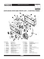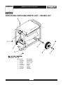
1
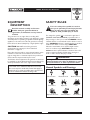
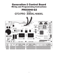
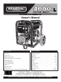
Owner’s Manual
Parts Included*
Table of Contents
• Generator
• Wheel kit
• Storage Cover
• Battery charge cables
• Spare Spark Plug, Air Filter, and Oil Filter
• Spark Plug Wrench
• Locking 20 Amp plug
• Locking 30 Amp plug
• Engine oil
• Owner's manual
• Engine manual
*If any parts are missing or damaged, call 1-800-270-1408.
Safety Rules . . . . . . . . . . . . . . . . . . . . . . . . . . . . . . . . . . . . 2-4
Know Your Generator . . . . . . . . . . . . . . . . . . . . . . . . . . . . . 5
Assembly . . . . . . . . . . . . . . . . . . . . . . . . . . . . . . . . . . . . . . 6-7
Operation . . . . . . . . . . . . . . . . . . . . . . . . . . . . . . . . . . . . 8-12
Product Specifications. . . . . . . . . . . . . . . . . . . . . . . . . . . . . 13
Maintenance . . . . . . . . . . . . . . . . . . . . . . . . . . . . . . . . . 13-14
Storage . . . . . . . . . . . . . . . . . . . . . . . . . . . . . . . . . . . . . . . . 14
Notes . . . . . . . . . . . . . . . . . . . . . . . . . . . . . . . . . . . . . . 15-16
Troubleshooting . . . . . . . . . . . . . . . . . . . . . . . . . . . . . . . . . 17
Schematic . . . . . . . . . . . . . . . . . . . . . . . . . . . . . . . . . . . . . . 18
Wiring Diagram . . . . . . . . . . . . . . . . . . . . . . . . . . . . . . . . . 19
Replacement Parts. . . . . . . . . . . . . . . . . . . . . . . . . . . . . 20-23
Warranty . . . . . . . . . . . . . . . . . . . . . . . . . . . . . . . . . Last Page
Questions? Help is just a moment away!
Call: Generac Generator Helpline - 1-800-270-1408 M-F 8-5 CT
Web: www.generac-portables.com or www.briggsandstratton.com
Model No. 9777-4 (4,000 Watt AC Generator) Manual No. 193524GS Revision 0 (08/04/2003)
4000XL Extended Life Generator
EQUIPMENT
DESCRIPTION
SAFETY RULES
This is the safety alert symbol. It is used to
alert you to potential personal injury hazards.
Obey all safety messages that follow this
symbol to avoid possible injury or death.
Read this manual carefully and become
familiar with your generator. Know its
applications, its limitations and any hazards
involved.
The generators are an engine–driven, revolving field,
alternating current (AC) generator. It was designed to supply
electrical power for operating compatible electrical lighting,
appliances, tools and motor loads.The generator’s revolving
field is driven at about 3,600 rpm by a single-cylinder engine.
The safety alert symbol ( ) is used with a signal word
(DANGER, CAUTION,WARNING), a pictorial and/or a
safety message to alert you to hazards. DANGER indicates
a hazard which, if not avoided, will result in death or serious
injury. WARNING indicates a hazard which, if not avoided,
could result in death or serious injury. CAUTION
indicates a hazard which, if not avoided, might result in
minor or moderate injury. CAUTION, when used
without the alert symbol, indicates a situation that could
result in equipment damage. Follow safety messages to
avoid or reduce the risk of injury or death.
CAUTION! DO NOT exceed the generator’s
wattage/amperage capacity. See “Don’t Overload
Generator” on page 12.
Every effort has been made to ensure that information in this
manual is accurate and current. However, we reserve the
right to change, alter or otherwise improve the product and
this document at any time without prior notice.
The Emission Control System for this generator is warranted
for standards set by the Environmental Protection Agency. For
warranty information refer to the engine owner’s manual.
In the State of California a spark arrester is required by law
(Section 4442 of the California Public Resources Code).
Other states may have similar laws. Federal laws apply on
federal lands. If you equip the muffler with a spark arrester,
it must be maintained in effective working order.
WARNING
The engine exhaust from this product contains
chemicals known to the State of California to cause
cancer, birth defects, or other reproductive harm.
Hazard Symbols and Meanings
Electrocution
Toxic Fumes
Explosive Pressure
2
Electrical Shock
Explosion
Chemical Burn
Electrical Shock
Fire
Hot Surface
4000XL Extended Life Generator
WARNING
DANGER
Running generator gives off carbon monoxide,
an odorless, colorless, poison gas.
Breathing carbon monoxide will cause nausea,
fainting or death.
Fuel and its vapors are extremely flammable and
explosive.
Fire or explosion can cause severe burns or
death.
• Operate generator ONLY outdoors.
WHEN ADDING FUEL
• Keep at least 2 feet of clearance on all sides of generator for
adequate ventilation.
• Turn generator OFF and let it cool at least 2 minutes before
removing gas cap. Loosen cap slowly to relieve pressure in tank.
• DO NOT operate generator inside any building or enclosure,
including the generator compartment of a recreational vehicle (RV).
• Fill fuel tank outdoors.
• DO NOT overfill tank. Allow space for fuel expansion.
• Keep fuel away from sparks, open flames, pilot lights, heat, and
other ignition sources.
DANGER
Generator produces powerful voltage.
Failure to isolate generator from power utility
can result in death or injury to electric utility
workers due to backfeed of electrical energy.
• DO NOT light a cigarette or smoke.
WHEN OPERATING EQUIPMENT
• DO NOT tip engine or equipment at angle which causes fuel
to spill.
• When using generator for backup power, notify utility
company. Use approved transfer equipment to isolate
generator from electric utility.
• Use a ground circuit fault interrupter (GFCI) in any damp or
highly conductive area, such as metal decking or steel work.
• DO NOT touch bare wires or receptacles.
• DO NOT use generator with electrical cords which are worn,
frayed, bare or otherwise damaged.
• DO NOT operate generator in the rain.
• DO NOT handle generator or electrical cords while standing
in water, while barefoot, or while hands or feet are wet.
• DO NOT allow unqualified persons or children to operate or
service generator.
• This generator is not for use in mobile equipment or marine
applications.
WHEN TRANSPORTING OR REPAIRING EQUIPMENT
• Transport/repair with fuel tank EMPTY or with fuel shutoff
valve OFF.
• Disconnect spark plug wire.
WHEN STORING FUEL OR EQUIPMENT WITH FUEL
IN TANK
• Store away from furnaces, stoves, water heaters, clothes
dryers or other appliances that have pilot light or other
ignition source because they can ignite fuel vapors.
DANGER
WARNING
Storage batteries give off explosive hydrogen gas
during recharging.
Hydrogen gas stays around battery for a long
time after battery has been charged.
Slightest spark will ignite hydrogen and cause
explosion.
You can be blinded or severely injured.
Battery electrolyte fluid contains acid and is
extremely caustic.
Contact with battery fluid will cause severe
chemical burns.
• This generator does not meet U. S. Coast Guard Regulation
33CFR-183 and should not be used on marine applications.
• Failure to use the appropriate U. S. Coast Guard approved
generator could result in bodily injury and/or property
damage.
• DO NOT allow any open flame, spark, heat, or lit cigarette
during and for several minutes after charging a battery.
• Wear protective goggles, rubber apron, and rubber gloves.
3
4000XL Extended Life Generator
CAUTION
WARNING
Exceeding generators wattage/amperage capacity can
damage generator and/or electrical devices connected
to it.
Unintentional sparking can result in fire or
electric shock.
• See “Don’t Overload Generator” on page 12.
• Start generator and let engine stabilize before connecting
electrical loads.
• Connect electrical loads in OFF position, then turn ON for
operation.
• Turn electrical loads OFF and disconnect from generator
before stopping generator.
WHEN ADJUSTING OR MAKING REPAIRS TO YOUR
GENERATOR
• Disconnect the spark plug wire from the spark plug and place
the wire where it cannot contact spark plug.
WARNING
CAUTION
Running engines produce heat.Temperature of
muffler and nearby areas can reach or exceed
150°F (65°C).
Severe burns can occur on contact.
Improper treatment of generator can damage it and
shorten its life.
• Use generator only for intended uses.
• If you have questions about intended use, ask dealer or call
1-800-270-1408.
• Operate generator only on level surfaces.
• DO NOT expose generator to excessive moisture, dust, dirt,
or corrosive vapors.
• DO NOT insert any objects through cooling slots.
• If connected devices overheat, turn them off and disconnect
them from generator.
• Shut off generator if:
-electrical output is lost;
-equipment sparks, smokes, or emits flames;
-unit vibrates excessively.
• DO NOT touch hot surfaces.
• Allow equipment to cool before touching.
CAUTION
Excessively high operating speeds increase risk of injury
and damage to generator.
Excessively low speeds impose a heavy load.
• DO NOT tamper with governed speed. Generator supplies
correct rated frequency and voltage when running at governed
speed.
• DO NOT modify generator in any way.
4
4000XL Extended Life Generator
KNOW YOUR GENERATOR
Read this owner’s manual and safety rules before operating your generator.
Compare the illustrations with your generator, to familiarize yourself with the locations of various controls and
adjustments. Save this manual for future reference.
Recoil Starter
Fuel Tank
Oil Fill Cap
Circuit Breakers (AC)
Run/Stop Switch
120/240 Volt AC,
20 Amp Receptacle
Choke Lever
120 Volt AC, 30 Amp
Receptacle
Air Cleaner
12 Volt DC, 10 Amp
Receptacle
120 Volt AC, 15 Amp
Duplex Receptacle
Spark Arrester Muffler
Idle Control Switch
Grounding Fastener
12 Volt DC,10 Amp Receptacle — Recharge a
discharged 12 Volt automotive type battery through this
receptacle.
120 Volt AC, 15 Amp Duplex Receptacle — May be
used to supply electrical power for the operation of
120 Volt AC, 15 Amp, single phase, 60 Hz electrical lighting,
appliance, tool and motor loads.
Circuit Breakers (AC) — Each receptacle is provided
with a "push to reset" circuit breaker to protect the
generator against electrical overload.
Fuel Tank — Capacity of 4.5 U.S. gallons.
Grounding Fastener — If required, please consult a
qualified electrician, electrical inspector, or the local agency
having jurisdiction.
Idle Control Switch — With this switch set to ON,
printed circuit board in control panel automatically reduces
engine speed when no load is connected and increases
engine to proper speed when load is applied. However, be
sure switch is OFF when starting engine.
Oil Fill Cap — Add oil to engine here.
Recoil starter — Used to start the engine manually.
Run/Stop Switch — Set this switch to "Run" before
using recoil starter. Set switch to "Stop" to switch OFF
engine.
Spark Arrester Muffler — Exhaust muffler lowers
engine noise and is equipped with a spark arrester screen.
120 Volt AC, 30 Amp Receptacle — May be used to
supply electrical power for the operation of 120 Volt AC,
30 Amp, single phase, 60 Hz electrical lighting, appliance,
tool and motor loads.
120/240 Volt AC, 20 Amp Receptacle — May be used
to supply electrical power for the operation of 120 and/or
240 Volt AC, 20 Amp, single phase, 60 Hz electrical lighting,
appliance, tool and motor loads.
Air Cleaner — Uses a dry type filter element and foam
pre–cleaner to limit the amount of dirt and dust sucked
into the engine.
Choke Lever — Used when starting a cold engine.
5
4000XL Extended Life Generator
ASSEMBLY
Install Wheel Kit
Your generator requires some assembly and is ready for
use after it has been properly serviced with the
recommended oil and fuel.
If you have any problems with the assembly of your
generator, please call the generator helpline at
1-800-270-1408.
To install the wheel kit, the following tools are required:
• Socket wrench with 1/2" or 13mm sockets
• Needle-nose pliers
Install Wheel Kit as follows: (See Figure 1)
1. Place bottom of the generator cradle on a flat, even
surface.Temporarily place unit on blocks to ease assembly.
2. Slide axle through both axle mounting brackets on
cradle frame, as shown.
3. Slide wheel over axle.
NOTE: Be sure to install both wheels with air pressure
valve on outboard side.
4. Retain wheel on axle with e-ring using a needle-nose
pliers.You may add the flat washer if desired.
5. Repeat step 3 and 4 to secure second wheel.
Remove Generator From Carton
1.
2.
3.
4.
5.
Set carton on a rigid flat surface with “This Side Up”
arrows pointing upward.
Carefully open top flaps of shipping carton. Review
“Cold Weather Operation” on page 10.
Cut down corners at one end of carton from top to
bottom and lay that side of carton down flat.
Remove all packing material, carton fillers, etc.
Remove generator from shipping carton.
Figure 1 — Install Wheel Kit
Cap Screw
Hex
nut
Flat Washer
Axle
Handle
Mounting Leg
Wheel
Use Existing Fasteners
6
E-Ring
4000XL Extended Life Generator
BEFORE STARTING
ENGINE
6.
Remove existing hardware from vibration mounts with
13mm wrench. Use same hardware to attach mounting leg.
7. Remove temporary blocks.
8. Center handle bracket on generator frame at control
panel end of cradle.
9. Attach handle bracket with two cap screws and two hex
nuts. Use two 13 mm wrenches to tighten hardware.
10. Check that all fasteners are tight and tires are inflated
between 15-40 PSI.
Add Engine Oil and Fuel
• Place generator on a level surface.
CAUTION
Any attempt to crank or start the engine before it has
been properly filled with the recommended oil will result
in equipment failure.
• Refer to engine manual for oil and fuel fill information.
• Damage to equipment resulting from failure to follow this
instruction will void warranty.
• Refer to engine owner’s manual and follow oil and fuel
recommendations and instructions.
NOTE: Check oil often during engine break–in. Refer to
engine owner’s manual for recommendations.
NOTE: The generator assembly rotates on a prelubricated
and sealed ball bearing that requires no additional
lubrication for the life of the bearing.
7
4000XL Extended Life Generator
USING THE GENERATOR
OPERATING THE
GENERATOR
System Ground
CAUTION
The generator has a system ground that connects the
generator frame components to the ground terminals on
the AC output receptacles.The system ground is connected
to the AC neutral wire (the neutral is bonded to the
generator frame).
Exceeding generators wattage/amperage capacity can
damage generator and/or electrical devices connected
to it.
• See “Don’t Overload Generator” on page 12.
• Start generator and let engine stabilize before connecting
electrical loads.
• Connect electrical loads in OFF position, then turn ON for
operation.
• Turn electrical loads OFF and disconnect from generator
before stopping generator.
Special Requirements
There may be Federal or State Occupational Safety and
Health Administration (OSHA) regulations, local codes, or
ordinances that apply to the intended use of the generator.
Please consult a qualified electrician, electrical inspector, or
the local agency having jurisdiction.
Starting the Engine
• In some areas, generators are required to be registered
with local utility companies.
Disconnect all electrical loads from the generator. Follow
these start instruction steps in numerical order:
• If the generator is used at a construction site, there may
be additional regulations which must be observed.
1.
Make sure unit is on a level surface.
IMPORTANT: Failure to start and operate unit on a level
surface will cause the unit not to start or shut down
during operation.
Connecting to a Building’s Electrical
System
2.
Connections for standby power to a building’s electrical
system must be made by a qualified electrician.The
connection must isolate the generator power from utility
power, and must comply with all applicable laws and
electrical codes.
Turn fuel valve to “On” position (Figure 2).
Figure 2 — Fuel Shut-off Valve
DANGER
Generator produces powerful voltage.
Failure to isolate generator from power utility
can result in death or injury to electric utility
workers due to backfeed of electrical energy.
3.
• When using generator for backup power, notify utility
company. Use approved transfer equipment to isolate
generator from electric utility.
• Use a ground fault circuit interrupter (GFCI) in any damp or
highly conductive area, such as metal decking or steel work.
• DO NOT touch bare wires or receptacles.
• DO NOT use generator with electrical cords which are worn,
frayed, bare or otherwise damaged.
• DO NOT operate generator in the rain.
• DO NOT handle generator or electrical cords while standing
in water, while barefoot, or while hands or feet are wet.
• DO NOT allow unqualified persons or children to operate or
service generator.
Make sure Idle Control switch is in “Off” position
(Figure 3).
Figure 3 — Idle Control Switch
3.
8
Start engine according to instructions given in engine
owner’s manual.
4000XL Extended Life Generator
Charging a Battery
NOTE: If engine still fails to start after 3 pulls, check for
proper oil level in crankcase.This unit is equipped with a
Low Oil Shutdown System. See engine manual.
Your generator has the capability of recharging a discharged
12 Volt automotive or utility style storage battery. DO
NOT use the unit to charge any 6 Volt batteries. DO NOT
use the unit to crank an engine having a discharged battery.
Connecting Electrical Loads
• Let engine stabilize and warm up for a few minutes after
starting.
DANGER
Storage batteries give off explosive hydrogen gas
during recharging.
Hydrogen gas stays near battery for a long time
after battery has been charged.
Slightest spark will ignite hydrogen and cause
explosion.
You can be blinded or severely injured.
Battery electrolyte fluid contains acid and is
extremely caustic.
Contact with battery fluid will cause severe
chemical burns.
• Plug in and turn on the desired 120 and/or 240 Volt AC,
single phase, 60 Hz electrical loads.
• DO NOT connect 240 Volt loads to the 120 Volt
receptacles.
• DO NOT connect 3–phase loads to the generator.
• DO NOT connect 50 Hz loads to the generator.
• DO NOT OVERLOAD THE GENERATOR. See
“Don’t Overload Generator” on page 12.
Stopping the Engine
1.
2.
3.
4.
5.
• DO NOT allow any open flame, spark, heat, or lit cigarette
during and for several minutes after charging a battery.
• Wear protective goggles, rubber apron, and rubber gloves.
Unplug ALL electrical loads from generator panel
receptacles. NEVER start or stop engine with electrical
devices plugged in and turned ON.
Move idle control switch to “Off” position.
Let engine run at no-load for several minutes to
stabilize internal temperatures of engine and generator.
To recharge 12 Volt batteries, proceed as follows:
1. Check fluid level in all battery cells. If necessary, add
ONLY distilled water to cover separators in battery
cells. DO NOT use tap water.
Turn engine off according to instructions given in the
engine owner’s manual.
2.
Move fuel valve to “Off” position.
3.
4.
Operating Automatic Idle Control
This switch is designed to greatly improve fuel economy.
When this switch is turned ON, the engine will only
run at its normal high governed engine speed when
electrical loads are connected.When an electrical load is
removed, the engine will run at a reduced speed.
5.
If battery is equipped with vent caps, make sure they
are installed and are tight.
If necessary, clean battery terminals.
Connect battery charge cable connector plug to panel
receptacle identified by the words “12-VOLTS D.C.”.
Connect battery charge cable clamp with red handle
to the positive (+) battery terminal (Figure 4).
Figure 4 — Battery Connections
With the switch off, the engine will run at the normal
high engine speed. Always have the switch off when
starting and stopping the engine.
9
4000XL Extended Life Generator
6.
Connect battery charge cable clamp with black handle
to the negative (–) battery terminal (Figure 4).
7.
Start engine. Let engine run while battery recharges.
8.
When battery has charged, shut down engine
DANGER
Running generator gives off carbon monoxide,
an odorless, colorless, poison gas.
Breathing carbon monoxide will cause nausea,
fainting or death.
NOTE: Use an automotive hydrometer to test battery
state of charge and condition. Follow the hydrometer
manufacturer’s instructions carefully. Generally, a battery is
considered to be at 100% state of charge when specific
gravity of its fluid (as measured by hydrometer) is 1.260 or
higher.
• Operate generator ONLY outdoors.
• Keep at least 2 feet of clearance on all sides of generator for
adequate ventilation.
• DO NOT operate generator inside any building or enclosure,
including the generator compartment of a recreational vehicle (RV).
• Remove generator from shelter when temperature is above
40°F [4°C].
COLD WEATHER
OPERATION
RECEPTACLES
CAUTION
Under certain weather conditions (temperatures below
40°F [4°C] and a high dew point), your generator may
experience icing of the carburetor and/or the crankcase
breather system.
Receptacles may be marked with rating value greater
than generator output capacity.
• NEVER attempt to power a device requiring more
amperage than generator or receptacle can supply.
• DO NOT overload the generator. See “Don’t Overload
Generator”.
Build a structure that will enclose three sides and the top
of the generator:
1.
Make sure entire muffler-side of generator is exposed.
Note that your generator may appear different from
that shown in Figure 5.
120 Volt AC, 15 Amp Receptacles
Each of these outlets is protected against overload by
15 Amp push-to-reset type circuit breakers (Figure 6).
Figure 5 — Temporary Cold Weather Shelter
Wind
2.
3.
4.
Figure 6 — 120 Volt AC, 15 Amp Duplex Receptacle
Ensure a minimum of two feet clearance between
open side of box and nearest object.
Face exposed end away from wind and elements.
Enclosure should hold enough heat created by
generator to prevent problems.
Use each outlet to operate 120 Volt, 60 Hz, single phase
loads requiring 1,800 (1.8 kW) watts at 15 Amps of current.
10
4000XL Extended Life Generator
120/240 Volt AC, 20 Amp Locking
Receptacle
Figure 8 — 120 Volt AC, 30 Amp, Locking Receptacle
3-Wire Cord Set
Use a NEMA L14-20 plug with this receptacle. Connect a
4-wire cord set rated for 250 Volts at 20 Amps (or greater)
(Figure 7).You can use the same 4-wire cord if you plan to
run a 120 Volt load.
NEMA L5-30
Neutral
120V
Figure 7 — 120/240 Volt AC, 20 Amp Receptacle
4-Wire Cord Set
Hot
240V
120V
120V
W (Neutral)
Ground (Green)
Use this receptacle to operate 120 Volt AC, 60 Hz, single
phase loads requiring up to 3,600 watts (3.6 kW) of power
at 30 Amps.The outlet is protected by a 30 Amp
push-to-reset circuit breaker.
Y (Hot)
NEMA L14-20
X (Hot)
12 Volt DC, 10 Amp Receptacle
Ground (Green)
This receptacle (Figure 9) allows you to recharge a 12 Volt
automotive or utility style storage battery with the battery
charge cables provided.
This receptacle powers 120/240 Volt AC, 60 Hz, single
phase loads requiring up to 2,400 watts of power at
20 Amps for 120 Volts; 4,000 watts of power (4.0 kW) at
16.7 Amps for 240 Volts.The outlet is protected by a
20 Amp push-to-reset circuit breaker.
Figure 9 — 12 Volt DC, 10 Amp Receptacle
120 Volt AC, 30 Amp Locking
Receptacle
Use a NEMA L5-30 plug with this receptacle. Connect a
3-wire cord set rated for 125 Volts AC at 30 Amps to the
plug (Figure 8).
This receptacle can not recharge 6 Volt batteries and can
not be used to crank an engine having a discharged battery.
See “Charging a Battery” on page 9 before attempting to
recharge a battery.This outlet is protected by a 10 Amp
self resetting circuit breaker.
11
4000XL Extended Life Generator
DON'T OVERLOAD YOUR
GENERATOR
4. Plug in and turn on the next load.
5. Again, permit the generator to stabilize.
6. Repeat steps 4 and 5 for each additional load.
NEVER add more loads than the generator capacity.Take
special care to consider surge loads in generator capacity,
as described above.
Capacity
You must make sure your generator can supply enough
rated (running) and surge (starting) watts for the items you
will power at the same time. Follow these simple steps:
1. Select the items you will power at the same time.
2. Total the rated (running) watts of these items.This is
the amount of power your generator must produce to
keep your items running. See Figure 10.
3. Estimate how many surge (starting) watts you will
need. Surge wattage is the short burst of power
needed to start electric motor-driven tools or
appliances such as a circular saw or refrigerator.
Because not all motors start at the same time, total
surge watts can be estimated by adding only the
item(s) with the highest additional surge watts to the
total rated watts from step 2.
Figure 10 - Wattage Reference Chart
Tool or Appliance
Essentials
Light Bulb - 75 watt
Deep Freezer
Sump Pump
Refrigerator/Freezer - 18 Cu. Ft.
Water Well Pump - 1/3 HP
Heating/Cooling
Window AC - 10,000 BTU
Window Fan
Furnace Fan Blower - 1/2 HP
Kitchen
Microwave Oven - 1000 Watt
Coffee Maker
Electric Stove - Single Element
Hot Plate
Family Room
DVD/CD Player
VCR
Stereo Receiver
Color Television - 27”
Personal Computer w/17” monitor
Other
Security System
AM/FM Clock Radio
Garage Door Opener - 1/2 HP
Electric Water Heater - 40 Gallon
DIY/Job Site
Quartz Halogen Work Light
Airless Sprayer - 1/3 HP
Reciprocating Saw
Electric Drill - 1/2 HP
Circular Saw - 7 1/4”
Miter Saw - 10”
Planer/Jointer - 6”
Table Saw/Radial Arm Saw - 10”
Air Compressor - 1-1/2 HP
Example:
Tool or Appliance
Window Air
Conditioner
Refrigerator
Deep Freezer
Television
Light (75 Watts)
Rated (Running)
Watts
1200
Additional Surge
(Starting) Watts
1800
800
500
500
75
3075 Total
Running Watts
1600
500
1800 Highest
Surge Watts
Total Rated (Running) Watts
= 3075
Highest Additional Surge Watts
= 1800
Total Generator Output Required = 4875
Power Management
To prolong the life of your generator and attached devices,
it is important to take care when adding electrical loads to
your generator.There should be nothing connected to the
generator outlets before starting it's engine.The correct
and safe way to manage generator power is to sequentially
add loads as follows:
1. With nothing connected to the generator, start the
engine as described in this manual.
2. Plug in and turn on the first load, preferably the largest
load you have.
3. Permit the generator output to stabilize (engine runs
smoothly and attached device operates properly.
Rated*
(Running)
Watts
Additional
Surge
(Starting)
Watts
75
500
800
800
1000
500
1200
1600
2000
1200
300
800
1800
600
1300
1000
1500
1500
2500
-
100
100
450
500
800
-
180
300
480
4000
520
-
1000
600
960
1000
1500
1800
1800
2000
2500
1200
960
1000
1500
1800
1800
2000
2500
*Wattages listed are approximate only. Check tool or
appliance for actual wattage.
12
4000XL Extended Life Generator
SPECIFICATIONS
NOTE: DO NOT use a garden hose to clean generator.
Water can enter engine fuel system and cause problems. In
addition, if water enters generator through cooling air slots,
some of the water will be retained in voids and cracks of
the rotor and stator winding insulation.Water and dirt
buildup on the generator internal windings will eventually
decrease the insulation resistance of these windings.
Maximum Surge Watts . . . . . . . . . . . . . . . . .6,600 watts
Continuous Wattage Capacity . . . . . . . . . . .4,000 watts
Power Factor . . . . . . . . . . . . . . . . . . . . . . . . . . . . . .1.0
Rated Maximum Continuous AC Load Current:
At 120 Volts . . . . . . . . . . . . . . . . . . . . . . .33.3 Amps
At 240 Volts . . . . . . . . . . . . . . . . . . . . . . .16.7 Amps
Phase . . . . . . . . . . . . . . . . . . . . . . . . . . . . . . . . .1–phase
Rated Frequency . . . . . . . . . . . . . . . . . . . . . . .60 Hertz
Fuel Tank Capacity . . . . . . . . . . . . . . . . . . . 4 U.S. gallons
Shipping Weight . . . . . . . . . . . . . . . . . . . . . . . . . 134 lbs.
WARNING
Unintentional sparking can result in fire or
electric shock.
GENERAL MAINTENANCE
RECOMMENDATIONS
WHEN ADJUSTING OR MAKING REPAIRS TO YOUR
GENERATOR
• Disconnect the spark plug wire from the spark plug and place
the wire where it cannot contact spark plug.
The Owner/Operator is responsible for making sure that
all periodic maintenance tasks are completed on a timely
basis; that all discrepancies are corrected; and that the unit
is kept clean and properly stored. NEVER operate a
damaged or defective generator.
Fuel Valve Maintenance
The fuel valve is equipped with a fuel sediment cup, screen,
retaining ring and o-ring that need to be cleaned every
6 months or 100 hours (whichever occurs first).
Engine Maintenance
1.
2.
See engine owner’s manual for instructions.
CAUTION
Move fuel valve to “Off” position.
Remove sediment cup from fuel valve. Remove o-ring,
retaining ring and screen from fuel valve (Figure 11).
Figure 11 — Fuel Valve Maintenance
Avoid prolonged or repeated skin contact with used
motor oil.
• Used motor oil has been shown to cause skin cancer in
certain laboratory animals.
• Thoroughly wash exposed areas with soap and water.
KEEP OUT OF REACH OF CHILDREN. DON'T
POLLUTE. CONSERVE RESOURCES. RETURN
USED OIL TO COLLECTION CENTERS.
Screen
Retaining Ring
Generator Maintenance
O-ring
Generator maintenance consists of keeping the unit clean
and dry. Operate and store the unit in a clean dry
environment where it will not be exposed to excessive
dust, dirt, moisture or any corrosive vapors. Cooling air
slots in the generator must not become clogged with
snow, leaves or any other foreign material.
Sediment Cup
3.
4.
13
Wash sediment cup, o-ring, retaining ring, and screen in
a nonflammable solvent. Dry them thoroughly.
Place screen, retaining ring, and o-ring into fuel valve.
Install sediment cup and tighten securely.
4000XL Extended Life Generator
5.
Generator Storage
Move fuel valve to “On” position, and check for leaks.
Replace o-ring if there is any leakage.
• Clean the generator as outlined in “Generator Cleaning”.
• Check that cooling air slots and openings on generator
are open and unobstructed.
Generator Cleaning
• Use a damp cloth to wipe exterior surfaces clean.
CAUTION
WARNING
Improper treatment of generator can damage it and
shorten its life.
Storage covers can be flammable.
• DO NOT place a storage cover over a hot generator.
• Let equipment cool for a sufficient time before placing the
cover on the equipment.
• DO NOT expose generator to excessive moisture, dust, dirt,
or corrosive vapors.
• DO NOT insert any objects through cooling slots.
• Use a soft bristle brush to loosen caked on dirt or oil.
• Use a vacuum cleaner to pick up loose dirt and debris.
• Use low pressure air (not to exceed 25 psi) to blow
away dirt. Inspect cooling air slots and opening on
generator.These openings must be kept clean and
unobstructed.
Engine Storage
See engine owner’s manual for instructions.
Other Storage Tips
• To prevent gum from forming in fuel system or on
essential carburetor parts, add fuel stabilizer into fuel
tank and fill with fresh gasoline. Run the unit for several
minutes to circulate the additive through the carburetor.
The unit and fuel can then be stored for up to
24 months. Fuel stabilizer can be purchased locally.
• DO NOT store gasoline from one season to another
unless it has been treated as described above.
• Replace fuel container if it starts to rust. Rust and/or dirt
in fuel can cause problems if it's used with this unit.
• Store in clean and dry area.
STORAGE
The generator should be started at least once every seven
days and allowed to run at least 30 minutes. If this cannot
be done and you must store the unit for more than
30 days, use the following guidelines to prepare it for
storage.
14
4000XL Extended Life Generator
NOTES
15
4000XL Extended Life Generator
NOTES
16
4000XL Extended Life Generator
TROUBLESHOOTING
Problem
No AC output is available, but
generator is running.
Generator runs good at no-load
but "bogs" down" when loads are
connected.
Generator will not start; or starts
and runs rough.
Cause
Correction
1.
One of the circuit breakers is
open.
1.
Reset circuit breaker.
2.
Fault in generator.
2.
Contact Authorized service
facility.
3.
Poor connection or defective
cord set.
3.
Check and repair.
4.
Connected device is bad.
4.
Connect another device that is in
good condition.
1.
Short circuit in a connected load.
1.
Disconnect shorted electrical
load.
2.
Generator is overloaded.
2.
See "Don't Overload Generator".
3.
Shorted generator circuit.
3.
Contact Authorized service
facility.
Low oil level.
Fill crankcase to proper level or place
generator on level surface.
1.
Out of gasoline.
1.
Fill fuel tank.
Generator shuts down during
operation.
2.
Low oil level.
2.
Fill crankcase to proper level or
place generator on level surface.
Generator lacks power.
Load is too high.
See "Don't Overload Generator".
17
4000XL Extended Life Generator
SCHEMATIC
18
4000XL Extended Life Generator
WIRING DIAGRAM
19
4000XL Extended Life Generator
EXPLODED VIEW – MAIN UNIT
20
4000XL Extended Life Generator
PARTS LIST – MAIN UNIT
Item Part #
1 M189159GS
2 M84021GS
3 NSP
4 66365GS
5 84141JGS
6 83540JGS
7 65791GS
8 96796GS
9 73054GS
10 86307GS
11 47480GS
12 84508GS
13 B2153GS
14 83208GS
15 B4986GS
16 66476GS
17 89476GS
18 70644GS
19 84346GS
20 40976GS
21 83083GS
22 83071GS
23 81917GS
24 77816GS
25 SRV66825DGS
26 85652GS
27 67989GS
28 26850GS
29 84409GS
30 74908GS
31 87116GS
32 86308GS
33 65795GS
34 66849AGS
35 67022GS
36 84132GS
37 66386GS
38 66849GS
39 B4871GS
Description
CRADLE
SUPPORT, Engine, Red
ENGINE
HOUSING, Engine Adapter
ASSY, Rotor (Includes Item 7)
ASSY, Stator
BEARING
WASHER
DECAL, Fuel Shut Off
SCREW
SCREW
MOUNT,Vibration
SCREW
BRACKET, Muffler
DECAL, Ground
SCREW
GASKET, Exhaust
SCREW
SCREW
SCREW
SCREEN, Spark Arrest
MUFFLER
PIN, Roll
DECAL, Caution Hot Muffler
CARRIER, Rear Bearing
MOUNT,Vibration
NUT
WASHER
SLEEVING, Flexo
SCREW
ASSY, Control Panel (see page 22)
BOLT
RECTIFIER, Battery Charge
SCREW
GROMMET, Rubber
ASSY, Drive Module Pwr Reg.
ASSY, Brush Holder
SCREW
COVER, Bearing Carrier
Item Part #
40 22145GS
41 86494GS
42 86292GS
43 52858GS
44 189134GS
45 93826GS
46 51731GS
47 189133GS
48 189759GS
49 189135GS
50 193574GS
51
52
53
54
55
56
57
58
59
J84042GS
84687GS
85000GS
14353621GS
23762GS
189568GS
92982GS
B1797GS
189137GS
Items Not Shown:
BB3061GS
43483GS
37806GS
70185GS
78601GS
65787GS
193524GS
A8926GS
84882GS
72347GS
84895GS
193575GS
Description
WASHER
SCREW,Wing
SCREW
NUT, Lock
GROMMET,Tank
DECAL, Operating Instructions
SCREW
VALVE,Tank (Includes Item 48)
KIT, Fuel Valve Repair
CAP,Tank Fuel,Vented
ASSY,Tank, Fuel
(Includes Items 47 & 48)
SHIELD, Heat
INSULATION
CLIP, Insulation
WIRE, Ground
WASHER
CLAMP, Hose
DECAL, Danger
CLIP,Tree
SPACER
OIL BOTTLE
PLUG, 250V 20A 4-Prong
PLUG, 125V 30A 3-Prong
OIL FILTER
AIR CLEANER
CABLE, Battery Charge
MANUAL, Owners
MANUAL, Engine
WRENCH, Spark Plug
SPARK PLUG
COVER, Storage
KIT, Decals
Optional Accessories Not Included:
84883GS
Cord Wrap
21
4000XL Extended Life Generator
EXPLODED VIEW AND PARTS LIST – CONTROL PANEL
Item Part #
1 83976GS
2 83975GS
3 66818GS
4 66821GS
5 68867CGS
6
7
8
9
10
11
12
68868CGS
75207AGS
75207GGS
82538GS
84134GS
83514GS
83970GS
Item Part #
13 84028GS
14 67022GS
15 85584GS
16 84543AGS
17 84543CGS
18 84198GS
19 84197GS
21 75476GS
22 22264GS
23 51715GS
24 84543BGS
25 84335GS
26 82542GS
Description
PANEL, Control
BOX, Control
OUTLET, 120 V AC, 15 A Duplex
OUTLET, 12 V DC
OUTLET, 120/240 V AC, 20 A
Locking
OUTLET, 120 V AC, 30 A Locking
BREAKER, Circuit
BREAKER, Circuit
SWITCH, On/Off Rocker
GROMMET, Rubber
BREAKER, Circuit
CONTROL BOARD, System
22
Description
TRANSFORMER, Idle Control
GROMMET, Rubber
BAR, Bus
SCREW
SCREW
SHIELD, Circuit Breaker
BAR, Circuit Breaker Retaining
SCREW
WASHER, Lock
NUT
SCREW
HARNESS,Wire
BAR, DC Outlet Retaining
4000XL Extended Life Generator
EXPLODED VIEW AND PARTS LIST – WHEEL KIT
Item Part #
1 189715GS
2 B1764GS
3 52858GS
4 39287GS
5 191267FGS
6 B4966GS
7 191265GS
8 22247GS
Description
ASSY, Handle
LEG, Mounting
NUT, Locking
SCREW
AXLE
WHEEL
E-RING
WASHER
23
GENERAC PORTABLE PRODUCTS OWNER WARRANTY POLICY Effective January 1, 2003
LIMITED WARRANTY
"Generac Portable Products is a licensed trademark of Briggs & Stratton Power Products. Briggs & Stratton Power Products will
repair or replace, free of charge, any part, or parts of the equipment** that are defective in material or workmanship or both.
Transportation charges on parts submitted for repair or replacement under this warranty must be borne by purchaser.This
warranty is effective for the time periods and subject to the conditions provided for in this policy. For warranty service, find your
nearest Authorized service dealer by calling 1-800-270-1408.Warranty service may only be performed by a Briggs & Stratton
Power Products Authorized service dealer.
THERE IS NO OTHER EXPRESS WARRANTY. IMPLIED WARRANTIES, INCLUDING THOSE OF MERCHANTABILITY AND
FITNESS FOR A PARTICULAR PURPOSE, ARE LIMITED TO THE TIME PERIOD SPECIFIED, OR TO THE EXTENT PERMITTED
BY LAW. ANY AND ALL IMPLIED WARRANTIES ARE EXCLUDED. LIABILITY FOR CONSEQUENTIAL DAMAGES UNDER
ANY AND ALL WARRANTIES ARE EXCLUDED TO THE EXTENT EXCLUSION IS PERMITTED BY LAW. Some countries or
states do not allow limitations on how long an implied warranty lasts, and some countries or states do not allow the exclusion
or limitation of incidental or consequential damages, so the above limitation and exclusion may not apply to you.This warranty
gives you specific legal rights and you may also have other rights that vary from country to country or state to state.”
WARRANTY PERIOD*
Equipment **
Pressure Washer
Portable Generator
Consumer Use
1 Year
2 Years (2nd year parts only)
Commercial Use
90 Days
1 Year
* The warranty period begins on the date of purchase by the first retail consumer or commercial end user, and continues for the
period of time stated in the table above. "Consumer use" means personal residential household use by a retail consumer.
"Commercial use" means all other uses, including use for commercial, income producing or rental purposes. Once equipment has
been used commercially, it shall thereafter be considered to be in commercial use for purposes of this warranty.
** The engine and starting batteries are warranted solely by the manufacturers of those products.
WARRANTY REGISTRATION IS NOT NECESSARY TO OBTAIN WARRANTY ON BRIGGS & STRATTON
POWER PRODUCTS EQUIPMENT. SAVE YOUR PROOF OF PURCHASE RECEIPT. IF YOU DO NOT PROVIDE
PROOF OF THE INITIAL PURCHASE DATE AT THE TIME WARRANTY SERVICE IS REQUESTED,THE
MANUFACTURING DATE OF THE EQUIPMENT WILL BE USED TO DETERMINE THE WARRANTY PERIOD.
About your equipment warranty:
We welcome warranty repair and apologize to you for being inconvenienced. Any Authorized service dealer may perform warranty
repairs. Most warranty repairs are handled routinely, but sometimes requests for warranty service may not be appropriate. For
example, warranty service would not apply if equipment damage occurred because of misuse, lack of routine maintenance, shipping,
handling, warehousing or improper installation. Similarly, the warranty is void if the manufacturing date or the serial number on the
equipment has been removed or the equipment has been altered or modified. During the warranty period, the Authorized service
dealer, at its option, will repair or replace any part that, upon examination, is found to be defective under normal use and service.
This warranty will not cover following repairs and equipment:
• Normal Wear: Outdoor power equipment, like all mechanical devices, needs periodic parts, service and replacement to
perform well.This warranty does not cover repair when normal use has exhausted the life of a part or the equipment.
• Installation and Maintenance: This warranty does not apply to equipment or parts that have been subjected to improper or
unauthorized installation or alteration and modification, misuse, negligence, accident, overloading, overspeeding, improper
maintenance, repair or storage so as, in our judgment, to adversely affect its performance and reliability.This warranty also does
not cover normal maintenance such as adjustments, fuel system cleaning and obstruction (due to chemical, dirt, carbon or lime,
etc.).
• Other Exclusions: Also excluded from this warranty are wear items such as quick couplers, oil gauges, belts, o-rings, filters,
pump packing, etc., pumps which have been run without water supplied or damage or malfunctions resulting from accidents,
abuse, modifications, alterations, or improper servicing or freezing or chemical deterioration. Accessory parts such as guns,
hoses, wands and nozzles are excluded from the product warranty. Also excluded is used, reconditioned, and demonstration
equipment; equipment used for prime power in place of utility power and equipment used in life support applications.
BRIGGS & STRATTON POWER PRODUCTS GROUP, LLC
JEFFERSON,WISCONSIN, U.S.A.