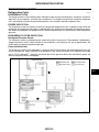
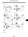
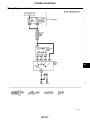
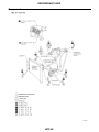
1
J AIR CONDITIONER
A
SECTION
MANUAL AIR CONDITIONER
B
C
D
CONTENTS
PRECAUTIONS .......................................................... 3
Precautions for Supplemental Restraint System
(SRS) “AIR BAG” and “SEAT BELT PRE-TENSIONER” .................................................................. 3
Precautions for Working with HFC-134a (R-134a)..... 3
Contaminated Refrigerant ........................................ 4
General Refrigerant Precautions .............................. 4
Precautions for Leak Detection Dye ......................... 4
A/C Identification Label ............................................ 5
Precautions for Refrigerant Connection ................... 5
FEATURES OF NEW TYPE REFRIGERANT
CONNECTION ...................................................... 5
O-RING AND REFRIGERANT CONNECTION..... 6
Precautions for Servicing Compressor ..................... 8
Precautions for Service Equipment .......................... 8
RECOVERY/RECYCLING EQUIPMENT .............. 8
ELECTRONIC LEAK DETECTOR ........................ 8
VACUUM PUMP ................................................... 9
MANIFOLD GAUGE SET ...................................... 9
SERVICE HOSES ................................................. 9
SERVICE COUPLERS ........................................ 10
CHARGING CYLINDER ...................................... 10
THERMOMETER AND HYGROMETER ............. 10
Wiring Diagrams and Trouble Diagnosis ................ 10
PREPARATION ..........................................................11
Special Service Tools ..............................................11
HFC-134a (R-134a) Service Tools and Equipment... 12
Commercial Service Tool ....................................... 14
REFRIGERATION SYSTEM ..................................... 15
Refrigeration Cycle ................................................. 15
REFRIGERANT FLOW ....................................... 15
FREEZE PROTECTION ..................................... 15
REFRIGERANT SYSTEM PROTECTION .......... 15
Component Layout ................................................. 16
LUBRICANT ............................................................. 17
Maintenance of Lubricant Quantity in Compressor... 17
LUBRICANT ........................................................ 17
CHECKING AND ADJUSTING ........................... 17
AIR CONDITIONER CONTROL ............................... 20
Control Operation ................................................... 20
FAN CONTROL KNOB ........................................ 20
MODE CONTROL KNOB .................................... 20
TEMPERATURE CONTROL KNOB .................... 20
RECIRCULATION (REC) SWITCH ..................... 20
AIR CONDITIONER SWITCH ............................. 20
REAR WINDOW DEFOGGER SWITCH (IF
EQUIPPED) ......................................................... 20
Discharge Air Flow ................................................. 21
TROUBLE DIAGNOSIS ............................................ 22
How to Perform Trouble Diagnoses for Quick and
Accurate Repair ...................................................... 22
WORK FLOW ...................................................... 22
SYMPTOM TABLE .............................................. 22
Component Location .............................................. 23
ENGINE COMPARTMENT .................................. 23
PASSENGER COMPARTMENT ......................... 26
Wiring Diagram — Heater — .................................. 27
Wiring Diagram — A/C — ....................................... 28
Operational Check .................................................. 30
CONDITIONS: ..................................................... 30
PROCEDURE: .................................................... 30
Mode Door .............................................................. 32
TROUBLE DIAGNOSIS PROCEDURE FOR
MODE DOOR ...................................................... 32
MODE DOOR CONTROL LINKAGE ADJUSTMENT .................................................................. 33
Intake Door ............................................................. 34
TROUBLE DIAGNOSIS PROCEDURE FOR
INTAKE DOOR .................................................... 34
INTAKE DOOR CIRCUIT .................................... 35
CONTROL LINKAGE ADJUSTMENT ................. 36
Blower Motor .......................................................... 37
TROUBLE DIAGNOSIS PROCEDURE FOR
BLOWER MOTOR .............................................. 37
BLOWER MOTOR CIRCUIT ............................... 37
ELECTRICAL COMPONENTS INSPECTION ..... 41
Magnet Clutch ........................................................ 42
TROUBLE DIAGNOSIS PROCEDURE FOR
MAGNET CLUTCH ............................................. 42
MAGNET CLUTCH CIRCUIT .............................. 43
MTC-1
E
F
G
H
I
MTC
K
L
M
ELECTRICAL COMPONENTS INSPECTION ..... 47
Insufficient Cooling ................................................. 49
TROUBLE DIAGNOSIS PROCEDURE FOR
INSUFFICIENT COOLING .................................. 49
PERFORMANCE TEST DIAGNOSES ................ 50
PERFROMANCE CHART ................................... 52
TROUBLE DIAGNOSES FOR ABNORMAL
PRESSURE ......................................................... 53
Insufficient Heating ................................................. 57
TROUBLE DIAGNOSIS PROCEDURE FOR
INSUFFICIENT HEATING ................................... 57
TEMPERATURE CONTROL LINKAGE
ADJUSTMENT .................................................... 58
Noise ...................................................................... 59
TROUBLE DIAGNOSIS PROCEDURE FOR
NOISE ................................................................. 59
Intake Sensor .......................................................... 60
COMPONENT DESCRIPTION ............................ 60
DIAGNOSTIC PROCEDURE .............................. 60
REMOVAL AND INSTALLATION ......................... 61
IN-CABIN MICROFILTER ......................................... 62
Removal and Installation ........................................ 62
FUNCTION .......................................................... 62
REPLACEMENT TIMING .................................... 62
REPLACEMENT PROCEDURES ....................... 62
HEATER CORE ......................................................... 63
Removal and Installation ........................................ 63
REMOVAL ........................................................... 63
INSTALLATION .................................................... 63
REFRIGERANT LINES ............................................. 64
HFC-134a (R-134a) Service Procedure ................. 64
SETTING OF SERVICE TOOLS AND EQUIPMENT .................................................................. 64
Components ............................................................66
Removal and Installation for Compressor ...............67
Removal and Installation for Compressor Clutch ...68
REMOVAL ............................................................69
INSPECTION AFTER REMOVAL ........................70
INSTALLATION ....................................................70
BREAK-IN OPERATION ......................................71
Thermal Protector Inspection ..................................72
Removal and Installation for Evaporator .................72
REMOVAL ............................................................72
INSTALLATION ....................................................72
Checking for Refrigerant Leaks ..............................72
PRELIMINARY CHECK .......................................72
Fluorescent Dye Leak Detector ..............................73
PRECAUTIONS FOR FLUORESCENT DYE
LEAK DETECTION ..............................................73
CHECKING SYSTEM FOR LEAKS USING THE
FLUORESCENT LEAK DETECTOR ...................73
DYE INJECTION ..................................................73
Electronic Refrigerant Leak Detector ......................74
PRECAUTIONS FOR HANDLING LEAK
DETECTOR .........................................................74
CHECKING PROCEDURE ..................................74
SERVICE DATA AND SPECIFICATIONS (SDS) ......77
General Specifications ............................................77
COMPRESSOR ...................................................77
LUBRICANT .........................................................77
REFRIGERANT ...................................................77
Inspection and Adjustment ......................................77
ENGINE IDLING SPEED (WHEN A/C IS ON) .....77
BELT TENSION ...................................................77
MAGNET CLUTCH ..............................................77
MTC-2
PRECAUTIONS
PRECAUTIONS
PFP:00001
Precautions for Supplemental Restraint System (SRS) “AIR BAG” and “SEAT
BELT PRE-TENSIONER”
A
EJS001ZK
The Supplemental Restraint System such as “AIR BAG” and “SEAT BELT PRE-TENSIONER”, used along
with a front seat belt, helps to reduce the risk or severity of injury to the driver and front passenger for certain
types of collision. This system may include seat belt switch inputs and dual stage front air bag modules. If
equipped with dual stage front air bag modules, the SRS system uses the seat belt switches to determine the
front air bag deployment, and may only deploy one front air bag, depending on the severity of a collision and
whether the front occupants are belted or unbelted. Information necessary to service the system safely is
included in the SRS and SB section of this Service Manual.
B
C
D
The vehicle may be equipped with a passenger air bag deactivation switch. Because no rear seat exists where
a rear-facing child restraint can be placed, the switch is designed to turn off the passenger air bag so that a
rear-facing child restraint can be used in the front passenger seat. The switch is located in the center of the
instrument panel, near the ashtray. When the switch is turned to the ON position, the passenger air bag is
enabled and could inflate for certain types of collision. When the switch is turned to the OFF position, the passenger air bag is disabled and will not inflate. A passenger air bag OFF indicator on the instrument panel lights
up when the passenger air bag is switched OFF. The driver air bag always remains enabled and is not affected
by the passenger air bag deactivation switch.
E
F
WARNING:
G
●
To avoid rendering the SRS inoperative, which could increase the risk of personal injury or death
in the event of a collision which would result in air bag inflation, all maintenance must be performed by an authorized NISSAN/INFINITI dealer.
H
●
Improper maintenance, including incorrect removal and installation of the SRS, can lead to personal injury caused by unintentional activation of the system. For removal of Spiral Cable and Air
Bag Module, see the SRS section.
I
●
Do not use electrical test equipment on any circuit related to the SRS unless instructed to in this
Service Manual. SRS wiring harnesses can be identified by yellow and/or orange harnesses or
harness connectors.
MTC
●
The vehicle may be equipped with a passenger air bag deactivation switch which can be operated
by the customer. When the passenger air bag is switched OFF, the passenger air bag is disabled
and will not inflate. When the passenger air bag is switched ON, the passenger air bag is enabled
and could inflate for certain types of collision. After SRS maintenance or repair, make sure the K
passenger air bag deactivation switch is in the same position (ON or OFF) as when the vehicle
arrived for service.
Precautions for Working with HFC-134a (R-134a)
EJS001ZL
WARNING:
●
CFC-12 (R-12) refrigerant and HFC-134a (R-134a) refrigerant are not compatible. If the refrigerants
are mixed, compressor failure is likely to occur. Refer to MTC-4, "Contaminated Refrigerant" . To
determine the purity of HFC-134a (R-134a) in the vehicle and recovery tank, use Refrigerant
Recovery/Recycling Recharging equipment and Refrigerant Identifier.
●
Use only specified lubricant for the HFC-134a (R-134a) A/C system and HFC-134a (R-134a) components. If lubricant other than that specified is used, compressor failure is likely to occur.
●
The specified HFC-134a (R-134a) lubricant rapidly absorbs moisture from the atmosphere. The following handling precautions must be observed:
–
When removing refrigerant components from a vehicle, immediately cap (seal) the component to
minimize the entry of moisture from the atmosphere.
–
When installing refrigerant components to a vehicle, do not remove the caps (unseal) until just
before connecting the components. Connect all refrigerant loop components as quickly as possible to minimize the entry of moisture into system.
–
Only use the specified lubricant from a sealed container. Immediately reseal containers of lubricant. Without proper sealing, lubricant will become moisture saturated and should not be used.
–
Avoid breathing A/C refrigerant and lubricant vapor or mist. Exposure may irritate eyes, nose and
throat. Remove R-134a from the A/C system, using certified service equipment meeting requirements of SAE J2210 (R-134a recycling equipment), or J2209 (R-134a recovery equipment). If acci-
MTC-3
L
M
PRECAUTIONS
–
dental system discharge occurs, ventilate work area before resuming service. Additional health
and safety information may be obtained from refrigerant and lubricant manufacturers.
Do not allow lubricant (Nissan A/C System Oil Type R) to come in contact with styrofoam parts.
Damage may result.
Contaminated Refrigerant
EJS001ZM
If a refrigerant other than pure R-134a is identified in a vehicle, your options are:
●
Explain to the customer that environmental regulations prohibit the release of contaminated refrigerant
into the atmosphere.
●
Explain that recovery of the contaminated refrigerant could damage your service equipment and refrigerant supply.
●
Suggest the customer return the vehicle to the location of previous service where the contamination may
have occurred.
●
If you choose to perform the repair, recover the refrigerant using only dedicated equipment and containers. Do not recover contaminated refrigerant into your existing service equipment. If your facility
does not have dedicated recovery equipment, you may contact a local refrigerant product retailer for available service. This refrigerant must be disposed of in accordance with all federal and local regulations. In
addition, replacement of all refrigerant system components on the vehicle is recommended.
●
If the vehicle is within the warranty period, the air conditioner warranty is void. Please contact Nissan Customer Affairs for further assistance.
General Refrigerant Precautions
EJS001ZN
WARNING:
●
Do not release refrigerant into the air. Use approved recovery/recycling equipment to capture the
refrigerant every time an air conditioning system is discharged.
●
Always wear eye and hand protection (goggles and gloves) when working with any refrigerant or
air conditioning system.
●
Do not store or heat refrigerant containers above 52°C (125°F).
●
Do not heat a refrigerant container with an open flame; if container warming is required, place the
bottom of the container in a warm pail of water.
●
Do not intentionally drop, puncture, or incinerate refrigerant containers.
●
Keep refrigerant away from open flames: poisonous gas will be produced if refrigerant burns.
●
Refrigerant will displace oxygen, therefore be certain to work in well ventilated areas to prevent
suffocation.
●
Do not pressure test or leak test HFC-134a (R-134a) service equipment and/or vehicle air conditioning systems with compressed air during repair. Some mixtures of air and R-134a have been
shown to be combustible at elevated pressures. These mixtures, if ignited, may cause injury or
property damage. Additional health and safety information may be obtained from refrigerant manufacturers.
Precautions for Leak Detection Dye
●
●
●
●
●
●
●
EJS001ZO
The A/C system contains a fluorescent leak detection dye used for locating refrigerant leaks. An ultraviolet
(UV) lamp is required to illuminate the dye when inspecting for leaks.
Always wear fluorescence enhancing UV safety glasses to protect your eyes and enhance the visibility of
the fluorescent dye.
A compressor shaft seal should not be repaired because of dye seepage. The compressor shaft seal
should only be repaired after confirming the leak with an electronic refrigerant leak detector (J-41995).
Always remove any dye from the leak area after repairs are complete to avoid a misdiagnosis during a
future service.
Do not allow dye to come into contact with painted body panels or interior components. If dye is spilled,
clean immediately with the approved dye cleaner. Fluorescent dye left on a surface for an extended period
of time cannot be removed .
Do not spray the fluorescent dye cleaning agent on hot surfaces (engine exhaust manifold, etc.).
Do not use more than one refrigerant dye bottle (1/4 ounce /7.4 cc) per A/C system.
MTC-4
PRECAUTIONS
●
●
Leak detection dyes for R-134a and R12 A/C systems are different. Do not use R-134a leak detection dye
in R-12 A/C system or R-12 leak detection dye in R-134a A/C systems or A/C system damage may result.
The fluorescent properties of the dye will remain for over three (3) years unless a compressor failure
occurs.
A/C Identification Label
EJS001ZP
Vehicles with factory installed fluorescent dye have this identification
label on the underside of hood.
NOTE:
Vehicles with factory installed fluorescent dye have a green label.
A
B
C
D
E
LHA242
Precautions for Refrigerant Connection
EJS001ZQ
A new type refrigerant connection has been introduced to all refrigerant lines except the following portion.
●
Thermal expansion valve connections.
F
G
FEATURES OF NEW TYPE REFRIGERANT CONNECTION
●
●
The O-ring is relocated in a groove for proper installation. This eliminates the chance of the O-ring being
caught in or damaged by the mating part. The sealing direction of the O-ring is now set vertically in relation to the contacting surface of the mating part to improve sealing characteristics.
The reaction force of the O-ring will not occur in the direction that causes the joint to pull out, thereby facilitating piping connections.
H
I
MTC
K
L
M
AHA534A
MTC-5
PRECAUTIONS
O-RING AND REFRIGERANT CONNECTION
WJIA0272E
CAUTION:
Refrigerant connections in some systems use different O-ring configurations. Do not confuse O-rings
since they are not interchangeable. If a wrong O-ring is installed, refrigerant will leak at or around the
connection.
MTC-6
PRECAUTIONS
O-Ring Part Numbers and Specifications
Connection type
New
O-ring
size
8
Former
New
12
Former
A
Part No.*
D
mm (in)
W
mm (in)
92471 N8210
6.8 (0.268)
1.85 (0.0728)
92470 N8200
6.07 (0.23990)
1.78 (0.0701)
92472 N8210
10.9 (0.429)
2.43 (0.0957)
92475 71L00
11.0 (0.433)
2.4 (0.094)
New
16
92473 N8210
13.6 (0.535)
2.43 (0.0957)
New
19
92474-N8210
16.5 (0.650)
2.43 (0.0957)
B
C
D
SHA814E
E
*: Always check with the Parts Department for the latest parts information.
WARNING:
Make sure all refrigerant is discharged into the recycling equipment and the pressure in the system is F
less than atmospheric pressure. Then gradually loosen the discharge side hose fitting and remove it.
CAUTION:
When replacing or cleaning refrigerant cycle components, observe the following.
G
●
When the compressor is removed, store it in the same position as it is when mounted on the car.
Failure to do so will cause lubricant to enter the low pressure chamber.
●
When connecting tubes, always use a torque wrench and a back-up wrench.
H
●
After disconnecting tubes, immediately plug all openings to prevent entry of dirt and moisture.
●
When installing an air conditioner in the vehicle, connect the pipes as the final stage of the operation. Do not remove the seal caps of pipes and other components until just before required for
I
connection.
●
Allow components stored in cool areas to warm to working area temperature before removing seal
caps. This prevents condensation from forming inside A/C components.
MTC
●
Thoroughly remove moisture from the refrigeration system before charging the refrigerant.
●
Always replace used O-rings.
●
When connecting tube, apply lubricant to circle of the O-rings as shown in illustration. Be careful K
not to apply lubricant to threaded portion.
Lubricant name: NISSAN A/C System Lubricant Type R
Part number: KLH00-PAGR0
L
●
O-ring must be closely attached to inflated portion of tube.
●
After inserting tube into union until O-ring is no longer visible, tighten nut to specified torque.
M
MTC-7
PRECAUTIONS
●
After connecting line, conduct leak test and make sure that there is no leakage. When the gas
leaking point is found, disconnect that line and replace the O-ring. Then tighten connections of
seal seat to the specified torque.
AHA514A
Precautions for Servicing Compressor
●
●
●
●
●
●
EJS001ZR
Plug all openings to prevent moisture and foreign matter from entering.
Do not keep the compressor in the upside down position or laid on its side for more than 10 minutes.
When replacing or repairing compressor, refer to MTC-17, "Maintenance of Lubricant Quantity in
Compressor" .
Keep friction surfaces between clutch and pulley clean. If the surface is contaminated with lubricant, wipe it off by using a clean waste cloth moistened with thinner.
After compressor service operation, turn the compressor shaft by hand more than five turns in
both directions. This will equally distribute lubricant inside the compressor. After the compressor
is installed, let the engine idle and operate the compressor for one hour.
After replacing the compressor magnet clutch, apply voltage to the new one and check for normal
operation.
Precautions for Service Equipment
EJS001ZS
RECOVERY/RECYCLING EQUIPMENT
Follow the manufacturer's instructions for machine operation and machine maintenance. Never introduce any
refrigerant other than that specified into the machine.
ELECTRONIC LEAK DETECTOR
Follow the manufacturer's instructions for tester operation and tester maintenance.
MTC-8
PRECAUTIONS
VACUUM PUMP
A
The lubricant contained inside the vacuum pump is not compatible
with the specified lubricant for HFC-134a (R-134a) A/C systems.
The vent side of the vacuum pump is exposed to atmospheric pressure so the vacuum pump lubricant may migrate out of the pump into
the service hose. This is possible when the pump is switched off
after evacuation (vacuuming) and hose is connected to it.
To prevent this migration, use a manual valve situated near the
hose-to-pump connection, as follows.
●
Usually vacuum pumps have a manual isolator valve as part of
the pump. Close this valve to isolate the service hose from the
pump.
●
For pumps without an isolator, use a hose equipped with a manual shut-off valve near the pump end. Close the valve to isolate
the hose from the pump.
●
If the hose has an automatic shut off valve, disconnect the hose
from the pump: when the hose is connected, the valve is open
and lubricating oil may migrate.
Some one-way valves open when vacuum is applied and close
under a no vacuum condition. Such valves may restrict the pump's
ability to pull a deep vacuum and are not recommended.
B
C
D
E
F
G
AHA559A
H
MANIFOLD GAUGE SET
Be certain that the gauge face indicates R-134a or 134a. Make sure
the gauge set has 1/2″-16 ACME threaded connections for service
hoses. Confirm the set has been used only with refrigerant HFC134a (R-134a) along with specified lubricant.
I
MTC
K
SHA533D
SERVICE HOSES
L
Be certain that the service hoses display the markings described
(colored hose with black stripe). All hoses must include positive shut
off devices (either manual or automatic) near the end of the hoses
opposite the manifold gauge.
M
AHA560A
MTC-9
PRECAUTIONS
SERVICE COUPLERS
Never attempt to connect HFC-134a (R-134a) service couplers to an
CFC-12 (R-12) A/C system. The HFC-134a (R-134a) couplers will
not properly connect to the CFC-12 (R-12) system. However, if an
improper connection is attempted, discharging and contamination
may occur.
Shut-off valve rotation
A/C service valve
Clockwise
Open
Counterclockwise
Close
RHA273D
CHARGING CYLINDER
Using a charging cylinder is not recommended. Refrigerant may be vented into air from cylinder's top valve
when filling the cylinder with refrigerant. Also, the accuracy of the cylinder is generally less than that of an
electronic scale or of quality recycle/recharge equipment.
THERMOMETER AND HYGROMETER
An etched stem-type thermometer and a hygrometer can be used to
check the air conditioning system performance. A hygrometer is
used because the air conditioning performance depends on the
humidity.
AHA274
Wiring Diagrams and Trouble Diagnosis
When you read wiring diagrams, refer to the following:
●
Refer to GI-13, "How to Read Wiring Diagrams" .
●
Refer to PG-9, "POWER SUPPLY ROUTING" .
When you perform trouble diagnosis, refer to the following:
●
Refer to GI-9, "HOW TO FOLLOW TEST GROUPS IN TROUBLE DIAGNOSES" .
●
Refer to GI-25, "How to Perform Efficient Diagnosis for an Electrical Incident" .
MTC-10
EJS001ZT
PREPARATION
PREPARATION
Special Service Tools
PFP:00002
A
EJS001ZU
The actual shapes of Kent-Moore tools may differ from those of special service tools illustrated here.
Tool number
(Kent-Moore No.)
Description
Tool name
KV99231260
(J-38874)
Clutch disc wrench
Removing shaft nut and clutch disc
B
C
D
NT204
KV99232340
(J-38874)
Clutch disc puller
Removing clutch disc
E
F
NT206
KV99234330
(J-39024)
Pulley installer
G
Installing pulley
H
I
NT207
KV99233130
(J-39023)
Pulley puller
Removing pulley
MTC
K
NT208
L
M
MTC-11
PREPARATION
HFC-134a (R-134a) Service Tools and Equipment
EJS001ZV
Never mix HFC-134a (R-134a) refrigerant and/or its specified lubricant with CFC-12 (R-12) refrigerant and/or
its lubricant.
Separate and non-interchangeable service equipment must be used for handling each type of refrigerant/lubricant.
Refrigerant container fittings, service hose fittings and service equipment fittings (equipment which handles
refrigerant and/or lubricant) are different between CFC-12 (R-12) and HFC-134a (R-134a). This is to avoid
mixed use of the refrigerants/lubricant.
Adapters that convert one size fitting to another must never be used or refrigerant/lubricant contamination will
occur and compressor failure will result.
Tool number
(Kent-Moore No.)
Tool name
Description
—
( — )
HFC-134a (R-134a) refrigerant
Container color: Light blue
Container marking: HFC-134a (R134a)
Fitting size: Thread size
●
large container 1/2″-16 ACME
S-NT196
KLH00-PAGS0
(
—
)
Genuine NISSAN A/C System Lubricant Type R
Type: Poly alkaline glycol oil (PAG),
type R
Application: HFC-134a (R-134a)
vane rotary compressors (NISSAN
only)
Lubricity: 40 m (1.4 US fl oz, 1.4
Imp fl oz)
S-NT197
Function: Refrigerant Recovery and
Recycling and Recharging
—
(J-39500-NI)
Recovery/Recycling
Recharging equipment (ACR2000)
WJIA0293E
—
(J-41995)
Electronic refrigerant leak detector
Power supply:
●
DC 12 V (Cigarette lighter)
Function: Checks for refrigerant
leaks.
AHA281A
(J-43926)
Refrigerant dye leak detection kit
Kit includes:
(J-42220) UV lamp and UV safety
glasses
(J-41459) Refrigerant dye injector
(J-41447) qty. 24
R-134a refrigerant dye
(J-43872) Refrigerant dye cleaner
Power supply:
DC 12V (Battery terminal)
SHA437F
MTC-12
PREPARATION
Tool number
(Kent-Moore No.)
Tool name
Description
(J-42220)
Fluorescent dye leak detector
Power supply: DC 12V (Battery terminal)
For checking refrigerant leak when
fluorescent dye is installed in A/C
system.
Includes: UV lamp and UV safety
glasses
A
B
C
LHA177
(J-41447)
HFC 134a (R134a) Fluorescent Leak
Detection Dye (Box of 24, 1/4 ounce
bottles)
Application: For R-134a PAG oil
Container: 1/4 ounce (7.4 cc) bottle
(Includes self-adhesive dye identification labels for affixing to vehicle
after charging system with dye.)
E
F
SHA439F
(J-41459)
HFC 134a (R134a) Dye Injector
Use with J-41447, 1/4 ounce bottle
D
For injecting 1/4 ounce of Fluorescent Leak Detection Dye into A/C
system.
G
H
SHA440F
(J-43872)
Dye cleaner
For cleaning dye spills.
I
MTC
SHA441F
(J-39183)
Manifold gauge set (with hoses and
couplers)
Identification:
●
The gauge face indicates R134a.
K
Fitting size: Thread size
●
1/2″-16 ACME
L
RJIA0196E
Service hoses
●
(J-39500-72B)
High side hose
●
(J-39500-72R)
Low side hose
●
(J-39500-72Y)
Utility hose
Hose color:
High side coupler
(J-39500-20A)
●
Low side coupler
(J-39500-24A)
Low hose: Blue with black stripe
●
High hose: Red with black stripe
●
Utility hose: Yellow with black
stripe or green with black stripe
Hose fitting to gauge:
S-NT201
Service couplers
●
●
●
1/2″-16 ACME
Hose fitting to service hose:
●
S-NT202
MTC-13
M14 x 1.5 fitting is optional or permanently attached.
M
PREPARATION
Tool number
(Kent-Moore No.)
Tool name
Description
(J-39699)
Refrigerant weight scale
For measuring of refrigerant
Fitting size: Thread size
●
1/2″-16 ACME
S-NT200
(J-39649)
Vacuum pump
(Including the isolator valve)
Capacity:
●
Air displacement: 4 CFM
●
Micron rating: 20 microns
●
Oil capacity: 482 g (17 oz)
Fitting size: Thread size
S-NT203
●
Commercial Service Tool
1/2″-16 ACME
EJS001ZW
Tool Number
Tool name
Description
(J-41810-NI)
Refrigerant identifier equipment HFC
134a (R-134a)
Checking for refrigerant purity and system
contamination
NT765
For details of handling methods, refer to the Instruction Manual attached to the service tool.
MTC-14
REFRIGERATION SYSTEM
REFRIGERATION SYSTEM
Refrigeration Cycle
PFP:KA990
A
EJS001ZX
REFRIGERANT FLOW
The refrigerant flows in the standard pattern. Refrigerant flows through the compressor, condenser, liquid tank,
expansion valve, evaporator, and back to the compressor. The refrigerant evaporation through the evaporator
coil is controlled by an externally equalized expansion valve, located inside the evaporator case.
FREEZE PROTECTION
B
C
The compressor cycles on and off to maintain the evaporator temperature within a specified range. When the
evaporator coil temperature falls below a specified point, the intake sensor interrupts the compressor operation. When the evaporator coil temperature rises above the specification, the intake sensor allows compressor
operation.
D
REFRIGERANT SYSTEM PROTECTION
Refrigerant Pressure Sensor
E
The refrigerant system is protected against excessively high or low pressure. The protection is effected by a
refrigerant pressure switch switch located on the condenser. If the pressure falls out of specifications, the
switch opens to interrupt compressor operation.
F
Pressure Relief Valve
The refrigerant system is also protected by a pressure relief valve located on the flexible high pressure hose
near the compressor. When the pressure of refrigerant in the system increases to an abnormal level [more
than 3,727 kPa (38 kg/cm2 , 540 psi)], the release port on the pressure relief valve automatically opens and
releases refrigerant into the atmosphere.
G
H
I
MTC
K
L
M
WJIA0673E
MTC-15
REFRIGERATION SYSTEM
Component Layout
EJS001ZY
WHA331
MTC-16
LUBRICANT
LUBRICANT
Maintenance of Lubricant Quantity in Compressor
PFP:KLG00
A
EJS001ZZ
The lubricant in the compressor circulates through the system with the refrigerant. Add lubricant to compressor when replacing any component or after a large gas leakage occurred. It is important to maintain the specified amount.
If lubricant quantity is not maintained properly, the following malfunctions may result:
●
Lack of lubricant: May lead to a seized compressor
●
Excessive lubricant: Inadequate cooling (thermal exchange interference)
B
C
LUBRICANT
D
Name: NISSAN A/C System Lubricant Type R
Part number: KLH00-PAGR0
CHECKING AND ADJUSTING
Adjust the lubricant quantity according to the flowchart shown below.
1. LUBRICANT RETURN OPERATION
E
F
Can lubricant return operation be performed?
●
A/C system works properly.
●
There is no evidence of a large amount of lubricant leakage.
Yes or No
Yes
>> GO TO 2.
No
>> GO TO 3.
2. PERFORM LUBRICANT RETURN OPERATION, PROCEEDING AS FOLLOWS
Start engine, and set the following conditions:
Test condition
Engine speed: Idling to 1,200 rpm
A/C switch: ON
RECIRCULATION switch: OFF
Fan speed: Max. position
Temp. control: Optional [Set so that intake air temperature is 25 to 30°C (77 to 86°F).]
2. Perform lubricant return operation for about 10 minutes.
3. Stop engine.
CAUTION:
If excessive lubricant leakage is noted, do not perform the lubricant return operation.
G
H
I
1.
–
MTC
K
L
M
>> GO TO 3.
3. CHECK COMPRESSOR
Should the compressor be replaced?
Yes or No
Yes
>> Refer to MTC-18, "Lubricant Adjusting Procedure for Compressor Replacement" .
No
>> GO TO 4.
4. CHECK ANY PART
Is there any part to be replaced? (Evaporator, condenser, liquid tank or in case there is evidence of a large
amount of lubricant leakage.)
Yes or No
Yes
>> Refer to MTC-18, "Lubricant Adjusting Procedure for Components Replacement Except Compressor" .
No
>> Perform MTC-50, "PERFORMANCE TEST DIAGNOSES" .
MTC-17
LUBRICANT
Lubricant Adjusting Procedure for Components Replacement Except Compressor
After replacing any of the following major components, add the correct amount of lubricant to the system.
Amount of lubricant to be added
Lubricant to be added to
system
Part replaced
Amount of lubricant
m (US fl oz, Imp fl oz)
Remarks
Evaporator
75 (2.5, 2.6)
—
Condenser
75 (2.5, 2.6)
—
Liquid tank
5 (0.2, 0.2)
Add if compressor is not
replaced. *1
30 (1.0, 1.1)
Large leak
—
Small leak *2
In case of refrigerant leak
●
*1:
If compressor is replaced, addition of lubricant is included in the flow chart.
●
*2:
If refrigerant leak is small, no addition of lubricant is needed.
Lubricant Adjusting Procedure for Compressor Replacement
1.
2.
3.
4.
5.
6.
7.
8.
9.
Before connecting recovery/recycling equipment to vehicle, check recovery/recycling equipment gauges.
No refrigerant pressure should be displayed, recover refrigerant from equipment lines and then check
refrigerant purity.
Confirm refrigerant purity in supply tank using recovery/recycling equipment and refrigerant identifier.
Confirm refrigerant purity in vehicle A/C system using recovery/recycling equipment and refrigerant identifier.
Discharge refrigerant into the refrigerant recovery/recycling equipment. Measure lubricant discharged into
the recovery/recycling equipment.
Drain the lubricant from the old (removed) compressor into a graduated container and record the amount
of lubricant drained.
Drain the lubricant from the new compressor into a separate, clean container.
Measure an amount of new lubricant installed equal to amount drained from old compressor. Add this
lubricant to new compressor through the suction port opening.
Measure an amount of new lubricant equal to the amount recovered during discharging. Add this lubricant to new compressor through the suction port opening.
If the liquid tank also needs to be replaced, add an additional 5 m (0.2 US fl oz, 0.2 Imp fl oz) of lubricant
at this time.
MTC-18
LUBRICANT
Do not add this 5 m
(0.2 US fl oz, 0.2 Imp fl oz) of lubricant if only replacing the compressor.
A
B
C
D
E
F
G
H
I
MTC
RHA065DD
K
L
M
MTC-19
AIR CONDITIONER CONTROL
AIR CONDITIONER CONTROL
Control Operation
PFP:27500
EJS00200
WJIA0279E
FAN CONTROL KNOB
This knob turns the fan ON and OFF, and controls fan speed.
MODE CONTROL KNOB
This knob controls the direction of air flow through the front discharge outlets. The air conditioner compressor
turns on when the switch is turned to the defrost
or foot/defrost
position. It will remain on until the key
is turned off or the fan switch is turned off (it will remain off only while the fan is off).
TEMPERATURE CONTROL KNOB
This knob allows adjustment of the outlet air temperature.
RECIRCULATION (REC) SWITCH
OFF position: Outside air is drawn into the passenger compartment.
ON position: Interior air is recirculated inside the vehicle. The indicator lamp will also light.
AIR CONDITIONER SWITCH
The air conditioner switch controls the A/C system. When the switch is depressed with the fan ON, the A/C
relay is activated by the ECM allowing compressor operation. The indicator lamp will also light.
The air conditioner cooling function operates only when the engine is running and ambient air temperature is above 2°C (35°F).
REAR WINDOW DEFOGGER SWITCH (IF EQUIPPED)
OFF position: Rear window defogger is not operating.
ON position: Rear window defogger is operating.
MTC-20
AIR CONDITIONER CONTROL
Discharge Air Flow
EJS00201
A
B
C
D
E
F
G
H
I
MTC
K
L
M
WJIA0280E
*1
MTC-30
MTC-21
TROUBLE DIAGNOSIS
TROUBLE DIAGNOSIS
How to Perform Trouble Diagnoses for Quick and Accurate Repair
PFP:00004
EJS00202
WORK FLOW
LHA244
*1: MTC-30
*2: MTC-22
SYMPTOM TABLE
Symptom
Reference page
●
Blower motor does not rotate.
●
Go to “TROUBLE DIAGNOSIS PROCEDURE FOR
BLOWER MOTOR”.
MTC-37
●
Mode door does not change positions.
●
Go to “TROUBLE DIAGNOSIS PROCEDURE FOR
MODE DOOR”.
MTC-32
●
Intake door position does not change.
●
Go to “TROUBLE DIAGNOSIS PROCEDURE FOR
INTAKE DOOR”.
MTC-34
●
Magnet clutch does not engage when A/C switch and
fan switch are ON.
●
Go to “TROUBLE DIAGNOSIS PROCEDURE FOR
MAGNET CLUTCH ”.
MTC-42
●
Insufficient cooling
●
Go to “TROUBLE DIAGNOSIS PROCEDURE FOR
INSUFFICIENT COOLING”.
MTC-49
●
Insufficient heating
●
Go to “TROUBLE DIAGNOSIS PROCEDURE FOR
INSUFFICIENT HEATING”.
MTC-57
●
Noise
●
Go to “TROUBLE DIAGNOSIS PROCEDURE FOR
NOISE”.
MTC-59
MTC-22
TROUBLE DIAGNOSIS
Component Location
EJS00203
A
ENGINE COMPARTMENT
KA24DE Models
B
C
D
E
F
G
H
I
MTC
K
L
M
WJIA0674E
MTC-23
TROUBLE DIAGNOSIS
VG33E Models
WJIA0675E
MTC-24
TROUBLE DIAGNOSIS
VG33ER Models
A
B
C
D
E
F
G
H
I
MTC
K
L
M
WJIA0676E
MTC-25
TROUBLE DIAGNOSIS
PASSENGER COMPARTMENT
WJIA0277E
MTC-26
TROUBLE DIAGNOSIS
Wiring Diagram — Heater —
EJS00204
A
B
C
D
E
F
G
H
I
MTC
K
L
M
WJWA0037E
MTC-27
TROUBLE DIAGNOSIS
Wiring Diagram — A/C —
EJS00205
WJWA0038E
MTC-28
TROUBLE DIAGNOSIS
A
B
C
D
E
F
G
H
I
MTC
K
L
M
WJWA0092E
MTC-29
TROUBLE DIAGNOSIS
Operational Check
EJS00206
The purpose of the operational check is to confirm that the system operates as it should. The systems which
are checked are the blower, mode (discharge air), intake air (recirculation), temperature decrease, temperature increase, and A/C compressor.
CONDITIONS:
Engine running at normal operating temperature.
PROCEDURE:
1. Check Blower Motor
1.
Turn fan control knob to 1-speed.
Blower should operate on 1-speed.
2. Then turn fan control knob to 2-speed, and continue checking
blower speed until all four speeds are checked.
3. Leave blower on 4-speed.
If NG, go to MTC-37, "Trouble Diagnosis Procedure for Blower
Motor" .
If OK, continue with the check.
WHA317
2. Check Discharge Air
1.
Turn mode control knob to each mode position.
WHA318
2.
Confirm that discharge air comes out according to the air distribution table at left.
Refer to MTC-21, "Discharge Air Flow" .
If NG, go to MTC-32, "Trouble Diagnosis Procedure For Mode Door"
.
If OK, continue with next check.
AHA983
MTC-30
TROUBLE DIAGNOSIS
3. Check Recirculation
A
1.
Press recirculation switch.
Recirculation indicator should light.
2. Listen for intake door position to change (you should hear
blower sound change slightly).
If NG, go to MTC-34, "Trouble Diagnosis Procedure for Intake Door" .
If OK, continue with next check.
B
C
WHA319
D
4. Check Temperature Decrease
1. Turn temperature control knob to full cold.
2. Check for cold air at discharge air outlets.
If NG, go to MTC-49, "TROUBLE DIAGNOSIS PROCEDURE FOR
INSUFFICIENT COOLING" .
If OK, continue with next check.
E
F
G
WHA320
H
5. Check Temperature Increase
1. Turn temperature control knob to full hot.
2. Check for hot air at discharge air outlets.
If NG, go to MTC-57, "TROUBLE DIAGNOSIS PROCEDURE FOR
INSUFFICIENT HEATING" .
If OK, continue with next check.
I
MTC
K
WHA321
L
6. Check A/C Switch
1.
2.
Turn fan control knob to the desired (1 to 4 speed) position.
Push the A/C switch to turn ON the air conditioner.
The indicator lamp should come on when air conditioner is ON.
3. Confirm that the compressor clutch engages (audio or visual
inspection).
4. Check for cold air at the appropriate discharge air outlets.
If NG, go to MTC-42, "TROUBLE DIAGNOSIS PROCEDURE FOR
MAGNET CLUTCH" .
If OK, continue with next check.
If all operational checks are OK (symptom cannot be duplicated), go
WHA322
to GI-25, "How to Perform Efficient Diagnosis for an Electrical Incident" , and perform tests as outlined to simulate driving conditions environment. If symptom appears, refer to
MTC-22, "Symptom Table" and perform applicable trouble diagnoses procedures.
MTC-31
M
TROUBLE DIAGNOSIS
Mode Door
EJS00207
TROUBLE DIAGNOSIS PROCEDURE FOR MODE DOOR
Symptom:
●
Mode door does not change.
Inspection Flow
WHA325
*1: MTC-21
*2: MTC-33
*3: MTC-30
*4: MTC-22
MTC-32
TROUBLE DIAGNOSIS
MODE DOOR CONTROL LINKAGE ADJUSTMENT
A
Mode door control linkage
●
●
●
●
Turn mode door control knob to
position.
Set side link in DEF mode.
Pull on outer cable in direction of arrow and then clamp it.
After positioning mode door control cable, check that it
operates properly.
B
C
D
AHA121A
E
F
G
H
I
MTC
K
L
M
MTC-33
TROUBLE DIAGNOSIS
Intake Door
EJS00208
TROUBLE DIAGNOSIS PROCEDURE FOR INTAKE DOOR
Symptom:
●
Intake door position does not change in VENT, B/L or FOOT mode.
Inspection Flow
WHA326
*1: MTC-36
*2: MTC-30
*3: MTC-22
MTC-34
TROUBLE DIAGNOSIS
INTAKE DOOR CIRCUIT
A
SYMPTOM:
●
Intake door does not operate.
B
1. CHECK POWER FOR INTAKE DOOR MOTOR
1.
2.
3.
Disconnect intake door motor harness connector.
Turn ignition switch ON.
Check voltage between intake door motor harness connector M96 terminals + (Y/B), – (Y) and ground as
shown.
C
D
E
F
G
LHA268
OK or NG
OK
>> GO TO 3.
NG
>> GO TO 2.
H
2. CHECK INTAKE DOOR CIRCUIT
1.
2.
3.
I
Turn ignition switch OFF.
Disconnect air control harness connector.
Check continuity between air control harness connector M95 terminals 3 (Y/B), 11 (Y) and intake door MTC
motor harness connector M96 terminals + (Y/B), – (Y).
K
L
M
WHA312
NOTE:
Mode control knob should be in
OK or NG
OK
>> Check harness for short.
NG
>> Replace air control.
position.
MTC-35
TROUBLE DIAGNOSIS
3. CHECK INTAKE DOOR MOTOR
1. Reconnect intake door motor connector M96.
2. Turn ignition switch ON.
3. Observe intake door operation when the RECIRC switch is turned ON and OFF.
4. Intake door should change position.
OK or NG
OK
>> Check harness and connectors for open or short.
NG
>> Replace intake door motor.
AHA523A
CONTROL LINKAGE ADJUSTMENT
Intake Door Motor
1.
2.
3.
4.
5.
Install intake door motor on intake unit.
Ensure that the intake door motor lever is fitted into the slit portion of the intake door link.
Connect the intake door motor harness connector before installing the intake door motor.
Turn ignition switch on and press the recirculation switch.
Turn the mode control knob to VENT, B/L or FOOT mode.
Check that intake door motor operates properly when RECIRCULATION switch is turned ON and OFF.
AHA523A
MTC-36
TROUBLE DIAGNOSIS
Blower Motor
EJS00209
A
TROUBLE DIAGNOSIS PROCEDURE FOR BLOWER MOTOR
Symptom:
●
Blower motor does not rotate.
B
Inspection Flow
C
D
E
F
G
H
I
MTC
WHA323
*1: MTC-37
*2: MTC-30
*3: MTC-22
K
BLOWER MOTOR CIRCUIT
SYMPTOM:
●
Blower motor does not rotate.
L
1. DIAGNOSTIC PROCEDURE
M
Check if blower motor rotates properly at each fan speed.
Does not rotate at any speed>>GO TO 2.
Does not rotate at 1-3 speed>>GO TO 6.
Does not rotate at 4 speed>>GO TO 7.
2. CHECK FUSES
Check 15A fuse [No. 19, located in the fuse block (J/B)] and 15A fuse [No. 24, located in the fuse block (J/B)].
For fuse layout, refer to PG-9, "POWER SUPPLY ROUTING" .
Are fuses OK?
YES >> GO TO 3.
NO
>> GO TO 9.
MTC-37
TROUBLE DIAGNOSIS
3. CHECK BLOWER MOTOR POWER SUPPLY CIRCUIT
1.
2.
Disconnect blower motor harness connector.
Check voltage between blower motor harness connector M62
terminal 1 and ground.
Does battery voltage exist?
Yes
>> GO TO 4.
No
>> Check the following.
● If NG, repair harness or connector.
– Harness for open between blower motor and fuse
block (J/B).
– Harness connectors M27 and M62
AHA485A
4. CHECK BLOWER MOTOR GROUND CIRCUIT
1.
2.
3.
Disconnect blower motor harness connector.
Turn fan control knob to 4-speed.
Check continuity between blower motor harness connector M62
terminal 2 (L/W) and ground.
Continuity should exist.
OK or NG
OK
>> GO TO 5.
NG
>> Check the following. If NG, repair harness or connector.
● Harness for open between blower motor and ground.
● Harness connectors M57 and M62
WJIA0281E
5. CHECK BLOWER MOTOR
1.
2.
Disconnect blower motor harness connector.
Apply 12 volts to blower motor terminal 1 and ground to blower
motor terminal 2.
Does blower motor rotate?
Yes
>> Reconnect blower motor connector and go to MTC-37,
"Trouble Diagnosis Procedure for Blower Motor" .
No
>> Replace blower motor.
AHA455A
MTC-38
TROUBLE DIAGNOSIS
6. CHECK FAN RESISTOR
1.
2.
A
Disconnect fan resistor harness connector M61.
Check resistance between fan resistor terminals.
B
Terminal No.
(+)
1
(–)
Resistance
Ω
(Approx.)
2
0.2 - 0.3
3
0.8 - 1.0
4
2.0 - 2.4
OK or NG
OK
>> GO TO 7.
NG
>> Replace fan resistor.
C
D
AHA458A
E
7. CHECK FAN SWITCH
F
Disconnect fan switch harness connector M57 and check continuity
between terminals at each fan switch position.
G
H
I
AHA456A
MTC
K
L
AHA457A
OK or NG
OK
>> GO TO 8.
NG
>> Replace fan switch.
MTC-39
M
TROUBLE DIAGNOSIS
8. CHECK FAN SWITCH GROUND
1.
2.
Disconnect fan switch harness connector M57.
Check continuity between fan switch harness connector terminal
6 and ground.
Continuity should exist.
OK or NG
OK
>> Check the following.
● If NG, repair harness or connectors.
– Harness connectors M57, M61 and M62
– Harness for open or short between blower motor and
fan switch, fan resistor
NG
>> Repair harness or connector.
AHA078A
9. REPLACE FUSE
1. Replace fuse(s).
2. Activate the blower motor system.
Do the fuses blow when the front blower motor is activated?
Yes
>> GO TO 10.
No
>> INSPECTION END
10. CHECK BLOWER MOTOR POWER SUPPLY CIRCUIT FOR A SHORT
1.
2.
Disconnect battery cable and blower motor harness connector M62.
Check continuity between front blower motor harness connector M62 terminal 1 (L) and ground.
WHA311
Does continuity exist?
Yes
>> Check the following. If NG, repair harness or connector.
● Harness connectors M27 and M62
● Harness for short between blower motor and fuse block (J/B).
No
>> Check front blower motor. Refer to MTC-41, "Blower Motor" . If necessary, clear intake unit. If OK,
replace front blower motor.
MTC-40
TROUBLE DIAGNOSIS
ELECTRICAL COMPONENTS INSPECTION
Fan Switch
A
Check continuity between terminals at each switch position.
B
C
D
AHA456A
E
F
G
H
AHA457A
Blower Motor
I
Confirm smooth rotation of the blower motor.
●
Check that there are no foreign particles inside the intake unit.
MTC
K
L
AHA547A
Fan Resistor
M
Terminal No.
(+)
1
(–)
Resistance
Ω
(Approx.)
2
0.2 - 0.3
3
0.8 - 1.0
4
2.0 - 2.4
Check resistance between terminals.
AHA458A
MTC-41
TROUBLE DIAGNOSIS
Magnet Clutch
EJS0020A
TROUBLE DIAGNOSIS PROCEDURE FOR MAGNET CLUTCH
Symptom:
●
Magnet clutch does not engage when A/C switch and fan switch are ON.
Inspection Flow
WHA327
*1: MTC-70
*2: MTC-72
*3: MTC-43
*4: MTC-30
*5: MTC-22
*6: MA-15 (KA24DE models) or MA-24
(VG33E and VG33ER models)
MTC-42
TROUBLE DIAGNOSIS
MAGNET CLUTCH CIRCUIT
A
SYMPTOM:
●
Magnet clutch does not engage when A/C switch and fan switch are ON.
B
1. CHECK A/C COMPRESSOR POWER SUPPLY CIRCUIT
1.
2.
3.
Disconnect A/C compressor harness connector F15.
Press the A/C switch ON.
Do approx. 12 volts exist between A/C compressor connector F15 terminal 1 (G/B) and ground?
C
D
E
F
WHA232
Yes or No
Yes
>> GO TO 2.
No
>> GO TO 3.
G
H
2. CHECK A/C COMPRESSOR GROUND
I
Check continuity between A/C compressor connector F15 terminal 1
(B) and ground.
Continuity should exist.
OK or NG
OK
>> Refer to MTC-42, "TROUBLE DIAGNOSIS PROCEDURE FOR MAGNET CLUTCH" .
NG
>> ● Check thermal protector. Refer to MTC-48, "Thermal
Protector (KA24DE Models)" or MTC-48, "Thermal
Protector (VG33E and VG33ER Models)" .
● Check magnet clutch coil.
If NG, replace magnet clutch. Refer to MTC-68,
"Removal and Installation for Compressor Clutch" .
MTC
K
LJIA0004E
M
3. CHECK CIRCUIT CONTINUITY
1.
2.
L
Disconnect A/C relay.
Check circuit continuity between A/C relay connector E30 terminal 3 (G/B) and A/C compressor connector F15 terminal 1 (G/
B).
Continuity should exist.
3. Also, check harness for short.
OK or NG
OK
>> GO TO 4.
NG
>> Repair harness or connector.
WJIA0575E
MTC-43
TROUBLE DIAGNOSIS
4. CHECK INTAKE SENSOR CIRCUIT
Refer to MTC-60, "Intake Sensor" .
OK or NG
OK
>> GO TO 5.
NG
>> Repair as necessary.
5. CHECK A/C RELAY POWER SUPPLY CIRCUIT
1.
2.
Disconnect A/C relay.
Do approx. 12 volts exist between A/C relay connector E30 terminals 2 (G/OR), 5 (Y) and ground?
Yes or No
Yes
>> GO TO 6.
No
>> GO TO 12.
WJIA0576E
6. CHECK A/C RELAY
Refer to MTC-47, "A/C Relay" .
OK or NG
OK
>> GO TO 7.
NG
>> Replace A/C relay.
7. CHECK A/C RELAY
1.
2.
3.
GROUND CONTROL CIRCUIT
Reconnect A/C relay.
Engine running and A/C OFF.
Do approx. 12 volts exist between ECM harness connector F29 terminal 12 (P) and ground?
WHA307
Yes or No
Yes
>> GO TO 8.
No
>> Check the following. If NG, repair harness or connectors.
● Harness for open or short between A/C relay and ECM
MTC-44
TROUBLE DIAGNOSIS
8. CHECK ECM OUTPUT VOLTAGE
A
Do approx. 5 volts exist between air control harness connector M95
terminal 2 (L/Y) and ground?
Yes or No
Yes
>> GO TO 15.
No
>> GO TO 8.
B
C
D
LJIA0006E
9. CHECK CIRCUIT CONTINUITY
1.
2.
E
Disconnect refrigerant pressure sensor harness connector E3.
Check voltage from refrigerant pressure sensor E3 terminal 1
(G/R) to ground.
F
Do approx. 5 volts exist?
G
3. Also, check harness for short.
Yes or No
Yes
>> GO TO 10.
No
>> Repair harness or connector.
H
WJIA0677E
I
10. CHECK REFRIGERANT PRESSURE SENSOR
Refer to MTC-48, "Refrigerant Pressure Sensor" .
OK or NG
OK
>> GO TO 11.
NG
>> Replace refrigerant pressure sensor.
MTC
K
L
M
MTC-45
TROUBLE DIAGNOSIS
11. CHECK CIRCUIT CONTINUITY
1.
2.
Disconnect refrigerant pressure sensor harness connector E3.
Check circuit continuity between air control harness connector
M95 terminal 2 (L/Y) and refrigerant pressure sensor connector
E3 terminal 2 (L/Y).
Continuity should exist.
WJIA0678E
3.
Also check circuit continuity between refrigerant pressure sensor connector E3 terminal 1 (G/R) and ECM connector F29 terminal 21 (G/R).
Continuity should exist.
OK or NG
OK
>> Check ECM. Refer to EC-697
(VG33ER).
NG
>> Repair harness or connector.
(VG33E) or EC-1298
WJIA0679E
12. CHECK FUSES
Check 7.5A fuse (No. 29, located in the fuse and fusible link box) and 7.5A fuse (No. 35, located in the fuse
and fusible link box). For fuse layout, refer to PG-9, "POWER SUPPLY ROUTING" .
Are fuses OK?
YES >> Check the following.
● If NG, repair harness or connectors.
– Harness for open between fuse and fusible link box and A/C relay
NO
>> GO TO 13.
13. REPLACE FUSE
Replace fuse.
Does fuse blow when A/C is activated?
Yes
>> GO TO 14.
No
>> INSPECTION END
MTC-46
TROUBLE DIAGNOSIS
14. CHECK A/C RELAY POWER SUPPLY CIRCUITS FOR SHORT
1.
2.
A
Disconnect battery cable and A/C relay.
Check for continuity on A/C relay connector E30 terminals 2 (G/
OR), 5 (Y) to ground.
B
Continuity should not exist.
OK or NG
OK
>> Check the following.
● If NG, repair harness or connectors.
– Harness connectors M60, M95 and E30.
– Harness for open or short between fuse and fusible
link box and A/C relay, or air control.
NG
>> Repair harness or connector.
C
D
WJIA0577E
E
15. CHECK FAN SWITCH
1.
2.
3.
F
Disconnect fan switch connector M57.
Turn fan control knob to ON (any speed position except OFF).
Check continuity between fan switch terminals 1 and 6.
G
H
I
MTC
LHA235
OK or NG
OK
>> Check the following.
● If NG, repair harness or connectors.
– Harness connectors M57 and M95.
– Harness for open or short between fan switch and air control.
– If OK, replace air control.
NG
>> Replace fan switch.
K
L
M
ELECTRICAL COMPONENTS INSPECTION
A/C Relay
Check continuity between terminals 3 and 5.
Conditions
Continuity
12V direct current supply between terminals 1 and 2
Yes
No current supply
No
If NG, replace relay.
LHA160
MTC-47
TROUBLE DIAGNOSIS
Refrigerant Pressure Sensor
Check continuity between terminals.
High-pressure side line
Terminals
Low-pressure side
1-2
High-pressure side
pressure kPa (kg/cm2 ,
psi)
Operation
Continuity
Increasing to 157 - 216
(1.6 - 2.2, 23 - 31)
ON
Yes
Decreasing to 157 - 196
(1.6 - 2.0, 23 - 28)
OFF
No
Increasing to 2,648 2,844 (27 - 29, 384 - 412)
OFF
No
Decreasing to 1,373 1,765 (14 - 18, 199 - 256)
ON
Yes
WJIA0680E
Thermal Protector (KA24DE Models)
Temperature of compressor °C (°F)
Operation
Increasing to approx. 145 - 155 (293 - 311)
Turn OFF
Decreasing to approx. 130 - 140 (266 - 284)
Turn ON
AHA135A
Thermal Protector (VG33E and VG33ER Models)
Temperature of compressor °C (°F)
Operation
Increasing to approx. 145 - 155 (293 - 311)
Turn OFF
Decreasing to approx. 130 - 140 (266 - 284)
Turn ON
AHA402A
MTC-48
TROUBLE DIAGNOSIS
Insufficient Cooling
EJS0020B
A
TROUBLE DIAGNOSIS PROCEDURE FOR INSUFFICIENT COOLING
Symptom:
●
Insufficient cooling
B
Inspection Flow
C
D
E
F
G
H
I
MTC
K
L
M
WHA328
*1: MTC-32
*2: MTC-53
*3: MTC-50
*4: MTC-30
*5: MTC-22
*6: MTC-67
*7: MA-15 (KA24DE models) or MA-24
(VG33E and VG33ER models)
MTC-49
TROUBLE DIAGNOSIS
PERFORMANCE TEST DIAGNOSES
MHA649A
*1: MTC-52
*2: MTC-52
*3: MTC-53
MTC-50
TROUBLE DIAGNOSIS
A
B
C
D
E
F
G
H
I
MTC
K
L
M
WJIA0282E
*1: MTC-42
*2: MA-15 (KA24DE models) or MA-24
(VG33E and VG33ER models)
MTC-51
TROUBLE DIAGNOSIS
PERFROMANCE CHART
Test Condition
Testing must be performed as follows:
Vehicle location
Indoors or in the shade (in a well-ventilated place)
Doors
Closed
Door windows
Open
Hood
Open
TEMP. switch
Max. COLD
Mode switch
REC switch
(Ventilation) set
(Recirculation) set
(blower) speed
Engine speed
4-speed
1,500 rpm
Operate the air conditioning system for 10 minutes before taking measurements.
Test Reading
Recirculating-to-Discharge Air Temperature Table
Inside air (Recirculating air) at blower assembly inlet
Relative humidity %
50 - 60
60 - 70
Air temperature °C (°F)
Discharge air temperature at center ventilator °C (°F)
20 (68)
6.6 - 8.3 (44 - 47)
25 (77)
10.4 - 12.4 (51 - 54)
30 (86)
14.2 - 16.7 (58 - 62)
35 (95)
18.2 - 21 (65 - 70)
40 (104)
22.0 - 25.2 (72 - 77)
20 (68)
8.3 - 9.8 (47 - 50)
25 (77)
12.4 - 14.4 (54 - 58)
30 (86)
16.7 - 18.9 (62 - 66)
35 (95)
21.0 - 23.6 (70 - 74)
40 (104)
25.2 - 28.1 (77 - 83)
MTC-52
TROUBLE DIAGNOSIS
Ambient Air Temperature-to-Operating Pressure Table
A
Ambient air
Relative humidity %
cm2 , psi)
Low-pressure (Suction side) kPa (kg/cm2 ,
psi)
20 (68)
961 - 1,187 (9.8 - 12.1, 139 - 172)
108 - 157 (1.1 - 1.6, 16 - 23)
25 (77)
1,295 - 1,599 (13.2 - 16.3, 186 - 228)
161.8 - 215.8 (1.65 - 2.2, 23.5 - 31.3)
30 (86)
1,285 - 1,599 (13.1 - 16.0, 186 - 228)
167 - 216 (1.7 - 2.2, 24 - 31)
35 (95)
1,520 - 1,863 (15.5 - 19.0, 220 - 279)
235 - 284 (2.4 - 2.9, 34 - 41)
40 (104)
1,765 - 2,158 (18 - 22, 256 - 313)
289.3 - 353.1 (2.95 - 3.6, 41.9 - 51.2)
Air temperature °C
(°F)
50 - 70
High-pressure (Discharge side) kPa (kg/
B
C
D
TROUBLE DIAGNOSES FOR ABNORMAL PRESSURE
Whenever system's high and/or low side pressure is abnormal, diagnose using a manifold gauge. The marker
above the gauge scale in the following tables indicates the standard (normal) pressure range. Since the standard (normal) pressure, however, differs from vehicle to vehicle, refer to MTC-53, "Ambient Air Temperatureto-Operating Pressure Table" .
E
Both High- and Low-Pressure Sides Are Too High.
F
Gauge indication
Both high- and low-pressure sides
are too high.
Refrigerant cycle
●
Pressure is reduced soon
after water is splashed on
condenser.
Air suction by cooling fan is
insufficient.
Probable cause
Corrective action
Excessive refrigerant charge
in refrigeration cycle
Reduce refrigerant until specified pressure is obtained.
Insufficient condenser cooling
performance
↓
●
Clean condenser.
●
Check and repair cooling
fan as necessary.
G
H
1. Condenser fins are
clogged.
I
2. Improper fan rotation of
cooling fan
AC359A
●
Low-pressure pipe is not
cold.
●
When compressor is
stopped high-pressure
value quickly drops by
approximately 196 kPa (2
kg/cm2 , 28 psi). It then
decreases gradually thereafter.
Engine tends to overheat.
●
An area of the low-pressure
pipe is colder than areas
near the evaporator outlet.
●
Plates are sometimes covered with frost.
Poor heat exchange in condenser
(After compressor operation
stops, high pressure
decreases too slowly.)
↓
Air in refrigeration cycle
Evacuate repeatedly and
recharge system.
MTC
K
L
Engine cooling systems malfunction.
●
Excessive liquid refrigerant
on low-pressure side
●
Excessive refrigerant discharge flow
●
Expansion valve is open a
little compared with the
specification.
↓
1. Improper thermal valve
installation
2. Improper expansion valve
adjustment
MTC-53
Check and repair each engine
cooling system.
Replace expansion valve.
M
TROUBLE DIAGNOSIS
High-Pressure Side is Too High and Low-Pressure Side is Too Low.
Gauge indication
Refrigerant cycle
Probable cause
High-pressure side is too high and
low-pressure side is too low.
Upper side of condenser and
high-pressure side are hot,
however, liquid tank is not so
hot.
High-pressure tube or parts
located between compressor
and condenser are clogged or
crushed.
Corrective action
●
Check and repair or replace
malfunctioning parts.
●
Check lubricant for contamination.
AC360A
High-Pressure Side is Too Low and Low-Pressure Side is Too High.
Gauge indication
High-pressure side is too low and
low-pressure side is too high.
Refrigerant cycle
Probable cause
Corrective action
High and low-pressure sides
become equal soon after
compressor operation stops.
Compressor pressure operation is improper.
↓
Damaged inside compressor
packings
Replace compressor.
No temperature difference
between high and low-pressure sides
Compressor pressure operation is improper.
↓
Damaged inside compressor
packings.
Replace compressor.
AC356A
MTC-54
TROUBLE DIAGNOSIS
Both High- and Low-Pressure Sides are Too Low.
Gauge indication
Both high- and low-pressure sides
are too low.
Refrigerant cycle
●
There is a big temperature
difference between receiver
drier outlet and inlet. Outlet
temperature is extremely
low.
●
Liquid tank inlet and expansion valve are frosted.
●
Temperature of expansion
valve inlet is extremely low
as compared with areas
near liquid tank.
AC353A
●
Expansion valve inlet may
be frosted.
●
Temperature difference
occurs somewhere in highpressure side
●
Expansion valve and liquid
tank are warm or only cool
when touched.
There is a big temperature difference between expansion
valve inlet and outlet while the
valve itself is frosted.
Probable cause
Compressor discharge capacity does not change. (Compressor stroke is set at
maximum.)
Corrective action
●
Replace liquid tank.
●
Check lubricant for contamination.
High-pressure pipe located
between receiver drier and
expansion valve is clogged.
●
Check and repair malfunctioning parts.
●
Check lubricant for contamination.
Low refrigerant charge
↓
Leaking fittings or components
Check refrigerant for leaks.
Refer to MTC-72, "Checking
for Refrigerant Leaks" .
Expansion valve closes a little compared with the specification.
↓
●
Remove foreign particles by
using compressed air.
●
Check lubricant for contamination.
An area of the low-pressure
pipe is colder than areas near
the evaporator outlet.
Low-pressure pipe is clogged
or crushed.
Air flow volume is not enough
or is too low.
Evaporator is frozen.
↓
Compressor discharge capacity does not change. (Compressor stroke is set at
maximum length.)
●
Air conditioning system
does not function and does
not cyclically cool the compartment air.
MTC
●
Check and repair malfunctioning parts.
●
Check lubricant for contamination.
●
Check intake sesor operation. Refer to MTC-60,
"Intake Sensor" .
●
The system constantly functions for a certain period of
time after compressor is
stopped and restarted.
AC354A
MTC-55
K
L
Replace compressor.
M
Probable cause
Refrigerant does not discharge cyclically.
↓
Moisture is frozen at expansion valve outlet and inlet.
↓
Water is mixed with refrigerant.
H
I
Low-Pressure Side Sometimes Becomes Negative.
Refrigerant cycle
F
G
3. Outlet and inlet may be
clogged.
●
D
E
2. Malfunctioning thermal
valve
Low-pressure side sometimes
becomes negative.
B
C
1. Improper expansion valve
adjustment
Gauge indication
A
Corrective action
●
Drain water from refrigerant or replace refrigerant.
●
Replace liquid tank.
TROUBLE DIAGNOSIS
Low-Pressure Side Becomes Negative.
Gauge indication
Low-pressure side becomes negative.
Refrigerant cycle
Liquid tank or front/rear side
of expansion valve's pipe is
frosted or dewed.
Probable cause
Corrective action
High-pressure side is closed
and refrigerant does not flow.
↓
Expansion valve or liquid tank
is frosted.
Leave the system at rest until
no frost is present. Start it
again to check whether or not
the problem is caused by
water or foreign particles.
●
If water is the cause, initially
cooling is okay. Then the
water freezes causing a
blockage. Drain water from
refrigerant or replace refrigerant.
●
If due to foreign particles,
remove expansion valve
and remove particles with
dry and compressed air (not
shop air).
●
If either of the above methods cannot correct the
problem, replace expansion valve.
●
Replace liquid tank.
●
Check lubricant for contamination.
AC362A
MTC-56
TROUBLE DIAGNOSIS
Insufficient Heating
EJS0020C
A
TROUBLE DIAGNOSIS PROCEDURE FOR INSUFFICIENT HEATING
Symptom:
●
Insufficient heating
B
Inspection Flow
C
D
E
F
G
H
I
MTC
K
L
M
WJIA0283E
*1: MTC-58
*2: MTC-30
*3: MTC-22
*4: CO-13 (KA24DE models) or CO-28
(VG33E and VG33ER models)
*5: MA-16 (KA24DE models) or MA-26
(VG33E and VG33ER models)
*6: MTC-63
*7
CO-8 (KA24DE models) or CO-23
(VG33E and VG33ER models)
MTC-57
TROUBLE DIAGNOSIS
TEMPERATURE CONTROL LINKAGE ADJUSTMENT
Temperature Control Cable
●
When adjusting ventilator door rod and defrost door rod,
first disconnect mode control cable from side link. Reconnect and readjust mode control cable.
●
Turn temperature control knob to max. COLD position. Set air
mix door lever in full hot mode. Pull on outer cable in direction of
arrow and then clamp it.
●
After positioning temperature control cable, check that it
operates properly.
AHA120A
MTC-58
TROUBLE DIAGNOSIS
Noise
EJS0020D
A
TROUBLE DIAGNOSIS PROCEDURE FOR NOISE
Symptom:
●
Noise
B
Inspection Flow
C
D
E
F
G
H
I
MTC
K
L
M
LHA262
*1: MTC-68
*2: MTC-70
*3: MTC-17
*4: MA-15 (KA24DE models) or MA-24
(VG33E and VG33ER models)
MTC-59
TROUBLE DIAGNOSIS
Intake Sensor
EJS0020E
COMPONENT DESCRIPTION
Intake Sensor
The intake sensor is located on the heater and cooling unit. It converts temperature of air after it passes through the evaporator into a
resistance value which is then input to the air control.
After disconnecting intake sensor harness connector, measure resistance between terminals 1 and 2 at sensor harness side, using the
table below.
Temperature °C (°F)
Resistance kΩ
-15 (5)
12.34
-10 (14)
9.62
-5 (23)
7.56
0 (32)
6.00
5 (41)
4.80
10 (50)
3.87
15 (59)
3.15
20 (68)
2.57
25 (77)
2.12
30 (86)
1.76
35 (95)
1.47
40 (104)
1.23
45 (113)
1.04
WJIA0286E
If NG, replace intake sensor.
DIAGNOSTIC PROCEDURE
SYMPTOM: Intake sensor circuit is open or shorted.
WJIA0284E
1. CHECK INTAKE SENSOR CIRCUIT BETWEEN INTAKE SENSOR AND BODY GROUND
Disconnect intake sensor harness connector.
Terminal
Connector
Wire color
M60-2
B
Continuity
Body ground
Yes
OK or NG
OK
>> GO TO 2.
NG
>> Repair harness or connector.
WJIA0264E
MTC-60
TROUBLE DIAGNOSIS
2. CHECK INTAKE SENSOR CIRCUIT BETWEEN INTAKE SENSOR AND A/C CONTROL UNIT
A
Disconnect air control harness connector.
Terminals
Connector
M60-1
Wire color
RG
Continuity
Connector
Wire color
M95-12
RG
B
Yes
C
OK or NG
OK
>> GO TO 3.
NG
>> Repair harness or connector.
D
WJIA0285E
3. CHECK INTAKE SENSOR
E
Refer to MTC-60, "Intake Sensor" .
OK or NG
OK
>> Replace air control.
NG
>> Replace intake sensor.
F
REMOVAL AND INSTALLATION
G
1.
2.
Remove the evaporator. Refer to MTC-72, "REMOVAL" .
Remove the intake sensor clip and then the sensor.
CAUTION:
Be careful not to damage the core surface.
H
I
MTC
WJIA0100E
K
L
M
MTC-61
IN-CABIN MICROFILTER
IN-CABIN MICROFILTER
Removal and Installation
PFP:27277
EJS0020F
FUNCTION
The air inside the passenger compartment is kept clean on either the
recirculation mode or fresh mode by the in-cabin microfilter in the
blower unit.
LJIA0012E
REPLACEMENT TIMING
Replace the in-cabin microfilter at the recommended intervals. Refer
to the label. The in-cabin microfilter label is affixed inside the glove
box.
SHA868E
REPLACEMENT PROCEDURES
1.
2.
3.
4.
5.
Remove the glove box assembly. Refer to IP-10, "INSTRUMENT PANEL ASSEMBLY" .
Remove the in-cabin microfilter cover.
Take out the in-cabin microfilter from the blower unit.
Replace the old microfilter with a new in-cabin microfilter in the
blower unit.
Reinstall the glove box assembly.
LJIA0009E
MTC-62
HEATER CORE
HEATER CORE
Removal and Installation
PFP:27140
A
EJS0020G
B
C
D
E
F
G
H
I
AHA563A
MTC
REMOVAL
1.
2.
3.
4.
5.
6.
Drain the cooling system. Refer to MA-16, "DRAINING ENGINE COOLANT" (KA24DE) or MA-26,
"DRAINING ENGINE COOLANT" (VG33E and VG33ER).
Disconnect the two heater hoses from the engine compartment side.
Remove the cooling unit. Refer to MTC-72, "Removal and Installation for Evaporator" .
Remove the steering member assembly. Refer to IP-10, "INSTRUMENT PANEL ASSEMBLY" .
Remove the heater unit.
Remove the heater core.
INSTALLATION
K
L
M
Installation is in the reverse order of removal.
●
Inspect the engine cooling system for coolant leaks. Refer to MA-17, "REFILLING ENGINE COOLANT"
(KA24DE) or MA-26, "REFILLING ENGINE COOLANT" (VG33E and VG33ER).
MTC-63
REFRIGERANT LINES
REFRIGERANT LINES
HFC-134a (R-134a) Service Procedure
PFP:92600
EJS0020H
SETTING OF SERVICE TOOLS AND EQUIPMENT
WARNING:
Avoid breathing A/C refrigerant and lubricant vapor or mist. Exposure may irritate eyes, nose and
throat. Remove HFC-134a (R-134a) refrigerant from the A/C system using certified service equipment
meeting requirements of SAE J2210 HFC-134a (R-134a) recycling equipment or SAE J2201 HFC-134a
(R-134a) recovery equipment. If an accidental system discharge occurs, ventilate the work area before
resuming service. Additional health and safety information may be obtained from the refrigerant and
lubricant manufacturers.
Discharging Refrigerant
WJIA0668E
1.
Shut-off valve
2.
A/C service valve
3.
Recovery/Recycling equipment ACR 2000
(J-43600) with refrigerant identifier
Evacuating System and Charging Refrigerant
WJIA0669E
1.
Shut-off valve
2.
A/C service valve
MTC-64
3.
Recovery/Recycling equipment ACR
2000 (J-43600) with refrigerant identifier
REFRIGERANT LINES
4.
Refrigerant container (HFC-134a)
7.
Evacuating vacuum pump (J-39699)
5.
Weight scale (J-39650)
6.
Manifold gauge set (J-39183)
A
B
C
D
E
F
G
H
I
MTC
K
L
M
WJIA0530E
*1
MTC-17, "CHECKING AND
ADJUSTING"
*2
MTC-72, "Checking for Refrigerant
Leaks"
*4
MTC-50, "PERFORMANCE TEST
DIAGNOSES"
*5
MTC-4, "Contaminated Refrigerant"
MTC-65
*3
MTC-72, "Checking for Refrigerant
Leaks"
REFRIGERANT LINES
Components
EJS0020I
WJIA0681E
MTC-66
REFRIGERANT LINES
Removal and Installation for Compressor
EJS0020J
A
KA24DE
B
C
D
E
F
G
H
I
LHA236
VG33E AND VG33ER
MTC
K
L
M
LHA237
MTC-67
REFRIGERANT LINES
Removal and Installation for Compressor Clutch
EJS0020K
KA24DE
LJIA0008E
VG33E AND VG33ER
AHA507A
MTC-68
REFRIGERANT LINES
REMOVAL
1.
A
Remove the drive plate center bolt, hold clutch disc using Tool.
B
C
AHA841
2.
Remove the drive plate using Tool.
● Insert Tool's three pins into the drive plate. Rotate the Tool
clockwise to hook it onto the plate. Then, tighten the center
bolt to remove the drive plate.
● While tightening the center bolt, insert a round bar (such as a
suitable screwdriver) between two of the pins (as shown) to
prevent drive plate rotation. After removing the drive plate,
remove the shims from either the drive shaft or the drive plate.
D
E
F
G
AHA506A
3.
H
Remove the snap ring using suitable external snap ring pliers as
shown.
I
MTC
K
AHA843
4.
Remove the pulley assembly using a suitable pulley puller.
● Position the center of the pulley puller on the end of the drive
shaft. Remove the pulley assembly with the puller.
CAUTION:
For pressed pulleys:
To prevent the deformation of the pulley groove, the puller
claws should be hooked under (not into) the pulley groove.
L
M
RHA139E
5.
Remove the field coil harness clip using a suitable screwdriver.
MTC-69
REFRIGERANT LINES
6.
Remove the three field coil screws and remove the field coil.
RHA074C
INSPECTION AFTER REMOVAL
Clutch Disc
If the contact surface shows signs of damage due to excessive heat,
replace clutch disc and pulley.
RHA075C
Pulley
Check the appearance of the pulley assembly. If contact surface of pulley shows signs of excessive grooving,
replace clutch disc and pulley. The contact surfaces of the pulley assembly should be cleaned with a suitable
solvent before reinstallation.
Coil
Check coil for loose connection or cracked insulation.
INSTALLATION
1.
Install the field coil.
● Be sure to align the coil's pin with the hole in the compressor's
front head as shown.
● Install the field coil harness clip using a suitable screwdriver.
RHA076C
2.
Install the pulley assembly using the installer and a hand press,
and then install the snap ring using snap ring pliers.
AHA504A
MTC-70
REFRIGERANT LINES
3.
Install the drive plate on the drive shaft, together with the original
shim(s). Press the drive plate down by hand.
A
B
C
RHA078C
D
4.
Using the holder to prevent drive plate rotation, tighten the bolt
to specification.
Drive plate center bolt
5.
E
: 15 - 18 N·m (1.5 - 1.8 kg-m,
11- 13 ft-lb)
After tightening the bolt, check that the pulley rotates smoothly.
F
G
AHA847
6.
Check clearance all the way around the clutch disc.
Disc-to-pulley clearance
H
: 0.3 - 0.6 mm (0.012 - 0.024 in)
If the specified clearance is not obtained, replace adjusting
spacer and recheck.
I
MTC
K
L
M
AHA505A
BREAK-IN OPERATION
When replacing magnet clutch assembly, always conduct the break-in operation. This is done by engaging
and disengaging the clutch about 30 times. Break-in operation raises the level of transmitted torque.
MTC-71
REFRIGERANT LINES
Thermal Protector Inspection
●
●
EJS0020O
When servicing, do not allow foreign matter to get into compressor.
Check continuity between two terminals.
LJIA0010E
Removal and Installation for Evaporator
EJS0020P
AHA536A
REMOVAL
1.
2.
3.
4.
5.
6.
Discharge the A/C system. Refer to MTC-64, "Discharging
Refrigerant" .
Disconnect the two evaporator core refrigerant lines from the
engine compartment side.
● Cap the refrigerant lines to prevent moisture from entering the
system.
Remove the glove box and mating trim. Refer to IP-10,
"INSTRUMENT PANEL ASSEMBLY" .
Disconnect the thermal amp. connector.
Remove the cooling unit.
Separate the cooling unit case, and remove the evaporator.
AHA557A
INSTALLATION
Installation is in the reverse order of removal.
●
Recharge the A/C system. Refer to MTC-64, "HFC-134a (R-134a) Service Procedure" .
●
Inspect system for refrigerant leaks. Refer to MTC-72, "Checking for Refrigerant Leaks" .
Checking for Refrigerant Leaks
EJS0020Q
PRELIMINARY CHECK
●
Perform a visual inspection of all refrigeration parts, fittings, hoses and components for signs of A/C lubricant leakage, damage and corrosion. A/C lubricant leakage may indicate an area of refrigerant leakage.
MTC-72
REFRIGERANT LINES
●
●
●
Allow extra inspection time in these areas when using either an electronic refrigerant leak detector or fluorescent dye leak detector.
If dye is observed, confirm the leak with an electronic refrigerant leak detector. It is possible a prior leak
was repaired and not properly cleaned.
When searching for leaks, do not stop when one leak is found but continue to check for additional leaks at
all system components and connections.
When searching for refrigerant leaks using an electronic leak detector, move the probe along the suspected leak area at 25 - 50 mm (1 - 2 in)/sec. and no further than 6 mm (1/4 in) from the component.
NOTE:
Moving the electronic leak detector probe slower and closer to the suspected leak area will improve the
chances of finding a leak.
Fluorescent Dye Leak Detector
A
B
C
D
EJS0020R
PRECAUTIONS FOR FLUORESCENT DYE LEAK DETECTION
●
●
●
The fluorescent dye leak detector is not a replacement for an electronic refrigerant leak detector. The fluorescent dye leak detector should be used in conjunction with an electronic refrigerant leak detector (J41995) to pinpoint refrigerant leaks.
For your safety and your customer's satisfaction, read and follow all manufacturer's operating instructions
and precautions prior to performing the work.
Refer to MTC-4, "Precautions for Leak Detection Dye" .
CHECKING SYSTEM FOR LEAKS USING THE FLUORESCENT LEAK DETECTOR
E
F
G
1.
Check A/C system for leaks using the UV lamp and safety glasses (J-42220) in a low sunlight area (area
without windows preferable). Illuminate all components, fittings and lines. The dye will appear as a bright
green/yellow area at the point of leakage. Fluorescent dye observed at the evaporator drain opening indi- H
cates an evaporator core assembly (tubes, core or TXV) leak.
2. If the suspected area is difficult to see, use an adjustable mirror or wipe the area with a clean shop rag or
cloth, then check the cloth with the UV lamp for dye residue.
I
3. Confirm any suspected leaks with an approved electronic refrigerant leak detector.
4. After the leak is repaired, remove any residual dye using dye cleaner (J-43872) to prevent future misdiagnosis.
MTC
5. Perform a system performance check and verify the leak repair with an approved electronic refrigerant
leak detector.
K
DYE INJECTION
NOTE:
This procedure is only necessary when re-charging the system or when the compressor has seized and was
replaced.
Refer to MTC-4, "Precautions for Leak Detection Dye" .
1.
2.
3.
4.
5.
6.
7.
Check A/C system static (at rest) pressure. Pressure must be at least 345 kPa (3.52 kg/cm2 , 50 psi).
Pour one bottle (1/4 ounce /7.4 cc) of the A/C refrigerant dye into the injector tool (J-41459).
Connect the injector tool to the A/C LOW PRESSURE side service fitting.
Start engine and switch A/C ON.
When the A/C operating (compressor running), inject one bottle (1/4 ounce /7.4 cc) of fluorescent dye
through the low-pressure service valve using dye injector tool J-41459 (refer to the manufacturer's operating instructions).
With the engine still running, disconnect the injector tool from the service fitting.
CAUTION:
Be careful not to allow dye to spray or drip when disconnecting the injector from the system.
NOTE:
If repairing the A/C system or replacing a component, pour the dye directly into the open system connection and proceed with the service procedures.
Operate the A/C system for a minimum of 20 minutes to mix the dye with the system oil. Depending on the
leak size, operating conditions and location of the leak, it may take from minutes to days for the dye to
penetrate a leak and become visible.
MTC-73
L
M
REFRIGERANT LINES
Electronic Refrigerant Leak Detector
EJS0020S
PRECAUTIONS FOR HANDLING LEAK DETECTOR
NOTE:
●
When performing a refrigerant leak check, use a J-41995 A/C
leak detector or equivalent. Ensure that the instrument is calibrated and set properly per the operating instructions.
●
The leak detector is a delicate device. In order to use the leak
detector properly, read the operating instructions and perform
any specified maintenance.
●
Other gases in the work area or substances on the A/C components, for example, anti-freeze, windshield washer fluid, solvents and lubricants, may falsely trigger the leak detector. Make
sure the surfaces to be checked are clean. Clean with a dry
cloth or blow off with shop air.
●
Do not allow the sensor tip of the detector to contact any substance. This can also cause false readings and may damage the detector.
1. Position probe approximately 5 mm (3/16 in) away from point to
be checked.
AHA535A
SHA707EA
2.
When testing, circle each fitting completely with probe.
SHA706E
3.
Move probe along component approximately 25 - 50 mm (1 - 2
in)/sec.
SHA708EA
CHECKING PROCEDURE
NOTE:
To prevent inaccurate or false readings, make sure there is no refrigerant vapor, shop chemicals or smoke in
the vicinity of the vehicle. Perform the leak test in a calm area (low air/wind movement) so that the leaking
refrigerant is not dispersed.
1. Turn engine off.
MTC-74
REFRIGERANT LINES
2.
Connect a suitable A/C manifold gauge set to the A/C service ports.
Check if the A/C refrigerant pressure is at least 345 kPa (3.52 kg/cm2 , 50 psi) above 16°C (61°F). If less A
than specification, recover/evacuate and recharge the system with the specified amount of refrigerant.
Refer to MTC-64, "HFC-134a (R-134a) Service Procedure" .
B
NOTE:
At temperatures below 16°C (61°F), leaks may not be detected since the system may not reach 345 kPa
(3.52 kg/cm2 , 50 psi).
4. Conduct the leak test from the high side (compressor discharge a to evaporator f ) to the low side (evap- C
orator drain hose g to compressor suction k ). Refer to “MTC-66, "Components" . Perform a leak check
for the following areas carefully. Clean the component to be checked and move the leak detector probe
completely around the connection/component.
D
● Compressor
Check the fitting of high and low pressure hoses, relief valve and shaft seal.
● Liquid tank
E
Check the pressure switch, tube fitting, weld seams and the fusible plug mounts.
● Service valves
Check all around the service valves. Ensure service valve caps are secured on the service valves (to F
prevent leaks).
NOTE:
After removing A/C manifold gauge set from service valves, wipe any residue from valves to prevent
G
any false readings by leak detector.
● Cooling unit (evaporator)
With engine OFF, turn blower fan on “High” for at least 15 seconds to dissipate any refrigerant trace in
the cooling unit. Wait a minimum of 10 minutes accumulation time (refer to the manufacturer's recom- H
mended procedure for actual wait time) before inserting the leak detector probe into the drain hose.
(Keep the probe inserted for at least ten seconds.) Use caution not to contaminate the probe tip with
water or dirt that may be in the drain hose.
I
5. If a leak detector detects a leak, verify at least once by blowing compressed air into area of suspected
leak, then repeat check as outlined above.
6. Do not stop when one leak is found. Continue to check for additional leaks at all system components and MTC
connection.
If no leaks are found, perform steps 7 through 10.
7. Start engine.
K
8. Set the heater A/C control as follows:
a. A/C switch ON
L
b. Face mode
c. Recirculation switch ON
d. Max cold temperature
M
e. Fan speed high
9. Run engine at 1,500 rpm for at least 2 minutes.
10. Turn engine off and perform leak check again following steps 4
through 6 above.
● Refrigerant leaks should be checked immediately after stopping the engine. Begin with the leak detector at the compressor. The pressure on the high pressure side will gradually
drop after refrigerant circulation stops and pressure on the
low pressure side will gradually rise, as shown in the graph.
Some leaks are more easily detected when pressure is high.
11. Before connecting recovery/recycling equipment to vehicle,
check recovery/recycling equipment gauges. No refrigerant
SHA839E
pressure should be displayed. If pressure is displayed, recover
refrigerant from equipment lines and then check refrigerant
purity.
12. Confirm refrigerant purity in supply tank using recovery/recycling equipment and refrigerant identifier.
Refer to MTC-4, "Contaminated Refrigerant" .
3.
MTC-75
REFRIGERANT LINES
13. Confirm refrigerant purity in vehicle A/C system using recovery/recycling equipment and refrigerant identifier. Refer to MTC-4, "Contaminated Refrigerant" .
14. Discharge A/C system using approved refrigerant recovery equipment. Refer to MTC-64, "Discharging
Refrigerant" . Repair the leaking fitting or component as necessary.
15. Evacuate and recharge A/C system. Refer to MTC-64, "Evacuating System and Charging Refrigerant" .
Perform the leak test to confirm no refrigerant leaks.
16. Conduct A/C performance test to ensure system works properly.
MTC-76
SERVICE DATA AND SPECIFICATIONS (SDS)
SERVICE DATA AND SPECIFICATIONS (SDS)
General Specifications
PFP:00030
A
EJS0020T
COMPRESSOR
Model
DKV-14C
Type
Vane rotary
Displacement
B
140 (8.54)
cm3 (cu in)/rev.
Direction of rotation
C
Clockwise (viewed from drive end)
Drive belt
A type
D
LUBRICANT
Model
ZEXEL make
DKV-14C
Name
Genuine NISSAN A/C System Lubricant
Type R or equivalent
Part No.*
E
F
KLH00–PAGR0
Capacity (total in system)
m (US fl oz, Imp fl oz)
200 (6.8, 7.0)
G
*: Always check with the Parts Department for the latest parts information.
REFRIGERANT
Type
Capacity
H
HFC 134a (R-134a)
kg (lb)
0.60 - 0.70 (1.32 - 1.54)
g (oz)
600 - 700 (21.16 - 24.69)
Inspection and Adjustment
I
EJS0020U
ENGINE IDLING SPEED (WHEN A/C IS ON)
●
Refer to EC-36, "Idle Speed/Ignition Timing/Idle Mixture Ratio Adjustment" (KA24DE), EC-604, "Idle MTC
Speed/Ignition Timing/Idle Mixture Ratio Adjustment" (VG33E) or EC-1205, "Idle Speed/Ignition Timing/
Idle Mixture Ratio Adjustment" (VG33ER).
BELT TENSION
●
Refer to MA-15, "Checking Drive Belts"
VG33ER).
K
(KA24DE) or MA-24, "Checking Drive Belts"
(VG33E or
L
MAGNET CLUTCH
Model
DKV-14C
Clutch disc-pulley clearance
mm (in)
0.3 - 0.6 (0.012 - 0.024)
MTC-77
M
SERVICE DATA AND SPECIFICATIONS (SDS)
MTC-78