1
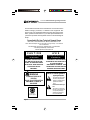
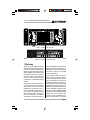
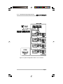
R.S.V.P.
Remote Switching Voltage Provider
120 VAC North
American
Units Only:
© 1998 by Crown International, Inc., P.O. Box 1000, Elkhart, IN
46515-1000 U.S.A. Telephone: 219-294-8000. Fax: 219-294-8329.
Trademark Notice: Crown ® is a registered trademark of Crown
International, Inc. Other trademarks are the property of their
respective owners.
®
Commercial
Audio
E106377
102539-1
2/98
R.S.V.P. Remote Switching Voltage Provider
The information furnished in this manual does not include all of the
details of design, production, or variations of the equipment. Nor
does it cover every possible situation which may arise during installation, operation or maintenance. If you need special assistance beyond the scope of this manual, please contact our Technical Support
Group.
Crown Audio Division Technical Support Group
Plant 2 SW, 1718 W. Mishawaka Rd., Elkhart, Indiana 46515 U.S.A.
Phone: 800-342-6939 (North America, Puerto Rico and Virgin Islands) or 219-294-8200
Fax: 219-294-8301
Fax Back (North America only): 800-294-4094 or 219-293-9200
Fax Back (International): 219-294-8100
Internet: http://www.crownaudio.com
CAUTION
AVIS
RISK OF ELECTRIC SHOCK
DO NOT OPEN
RISQUE DE CHOC ÉLECTRIQUE
N’OUVREZ PAS
TO PREVENT ELECTRIC SHOCK DO
NOT REMOVE TOP OR BOTTOM
COVERS. NO USER SERVICEABLE
PARTS INSIDE. REFER SERVICING
TO QUALIFIED SERVICE
PERSONNEL.
WARNING
TO REDUCE THE RISK OF
ELECTRIC
SHOCK, DO NOT EXPOSE THIS
EQUIPMENT TO RAIN OR
MOISTURE!
Printed on
recycled paper.
Page 2
À PRÉVENIR LE CHOC ÉLECTRIQUE
N’ENLEVEZ PAS LES COUVERCLES. IL
N’Y A PAS DES PARTIES
SERVICEABLE À L’INTÉRIEUR. TOUS
REPARATIONS DOIT ETRE FAIRE PAR
PERSONNEL QUALIFIÉ SEULMENT.
Watch for these symbols:
Lightning Bolt Symbol:
This symbol is used to alert
the user to the presence of
dangerous voltages and the
possible risk of electric
shock.
Exclamation Mark Symbol:
This symbol is used to alert
the user to make special note
of important operating or
maintenance instructions
found in the reference
manual.
R.S.V.P. Remote Switching Voltage Provider
Figure 1.1 R.S.V.P. top view
Figure 1.2 R.S.V.P. left side view
1 Welcome
Thank you for purchasing the Crown
R.S.V.P. (Remote Switching Voltage
Provider) accessory module, designed for use with Crown’s CT-10
series amplifiers. The R.S.V.P. takes
advantage of Crown’s CT-10 series’
soft-start feature, eliminating the
need for expensive sequencing
equipment or complicated startup
routines.
Using Crown’s R.S.V.P. module, you
can control the power-up/powerdown function of your CT-10 series
amplifier from across the room—or
across the stadium. Each R.S.V.P.
unit controls 21 amplifier remote
jacks. That’s enough to control a 6foot (1.83 meter) rack of amplifiers
and still have one jack left over to
chain to another R.S.V.P. Units are individually powered, allowing you to
daisy-chain any number of R.S.V.P.s
for remote control of an unlimited
number of amplifiers.
Power-up/power-down can be controlled using an auxiliary device
(such as an IQ System) via the aux
port, or through the use of a pair of
momentary switches. Remote momentary switches can be connected
in parallel, so your amps can be controlled from various locations: front of
house, backstage, lighting booth,
and so on. With a maximum switching distance of up to 2000 feet (609.6
meters) per unit, the R.S.V.P. can
provide on/off capabilities anywhere—or everywhere—you need it.
Page 3
R.S.V.P. Remote Switching Voltage Provider
Feature Summary
❏ Takes advantage of CT-10 series’ soft-start feature, eliminating the need for expensive sequencing equipment.
❏ Provides remote power-up/power-down of systems via a
simple momentary switch closure.
❏ Optional IQ System control for added security.
❏ Units are individually powered and can be daisy-chained to
control a limitless number of amplifiers.
❏ Each unit directly controls up to 21 amplifiers.
❏ Convenient connection system uses RJ-11 connectors for
quick and easy, cost-effective installation.
Page 4
R.S.V.P. Remote Switching Voltage Provider
Figure 2.1 Left Panel Facilities
2 Facilities
A. Enable Light
Green LED located on the left side
panel that indicates low voltage supply operation.
B. On/Com/Off
On, common, and off barrier block
input located on the left front panel
for connection of remote momentary
switches.
C. Slave/Aux In Port
RJ-11 connector located on the left
side panel that allows control from an
IQ System aux port. Also used for
daisy-chaining R.S.V.P. units together.
D. To Amplifier Remote
RJ-11 connectors located on the left
and right side panels for connecting
to CT-10 series amplifiers or daisychained R.S.V.P. units. (See Figures
3.2 and 3.3) Each R.S.V.P. can control 21 separate CT-10 series amplifiers, or the R.S.V.P. can be
daisy-chained to other R.S.V.P. units
to provide control over an unlimited
number of amplifiers. RJ-11 connectors are available from the Crown
Parts Department (219-294-8200).
E. AC Power Inlet
Standard IEC “three prong” AC connector located on the back panel.
F. Fuse Access Door
Located on the back panel, this allows access to the fuse in the event
that it needs to be changed. Please
refer to section 7.1 on changing the
fuse before trying to access this
area.
Figure 2.2 Rear Panel Facilities
Page 5
R.S.V.P. Remote Switching Voltage Provider
3 Installation
3.3 Wiring for Amplifiers
This section will give the necessary
information for installing the R.S.V.P.
into your equipment rack. It will also
provide ways to incorporate the
R.S.V.P. into your system. Please
read this section thoroughly, as the
R.S.V.P. has special cooling and
mounting requirements.
Convenient RJ-11 connectors link
the R.S.V.P. to the remote CT-10 series amplifiers. Please note that the
RJ-11 jacks are polarity sensitive. Pin
4 must be grounded, and Pin 3 must
be supplied with a positive voltage
pull up (positive with respect to
ground). Refer to Figure 3.1 for RJ
jack pin assignments.* The maximum signal that can be exposed to
the RJ-11 jacks is 35 VDC or 25 VAC.
(RJ-11 connectors are available from
the Crown Parts Department.)
3.1 Cooling
Make sure that the vent holes of
the R.S.V.P. are NOT obstructed.
When mounting the unit in the back
of your rack, avoid blocking air flow
to all of your rack-mounted equipment.
3.2 Mounting
The R.S.V.P. is designed to be
mounted in the REAR of a standard
19-inch (48.3-cm) equipment rack.
Placing it in the back of the rack provides a more tamper-resistant location and allows for easier access to
equipment. Four keyholes on the unit
can accomodate up to a #10 screw.
For a more secure installation, four
0.2- inch (0.5-cm) holes are also
available.
Figure 3.2 shows one possible system configuration using the R.S.V.P.
and a rack of CT-10 series amplifiers.
Runs of less than 30 feet (9.15
meters) between the R.S.V.P. and
the amplifiers are required for the
R.S.V.P. to function properly. Up to
21 CT-10 series amplifiers can be
controlled from a single R.S.V.P.
However, daisy- chaining together
units, as shown in Figure 3.3, can
provide for an unlimited number of
amplifiers in a system.
.
Figure 3.1 RJ-11 connector pin assignments
* The mating connector for the R.S.V.P. RJ-11 jack contains 4 contact pins in a 6-slot
case, as shown. For additional information please contact your local dealer or
Crown Technical Support.
Page 6
R.S.V.P. Remote Switching Voltage Provider
Figure 3.2 System Configuration—R.S.V.P. to CT-10 Series
Page 7
Figure 3.3 System Configuration—multiple R.S.V.P.s wired in a bus configuration
R.S.V.P. Remote Switching Voltage Provider
Page 8
Figure 3.5 System configuration with several R.S.V.P.s in a “star” configuration
Figure 3.4 System configuration with several R.S.V.P.s wired in a bus configuration
R.S.V.P. Remote Switching Voltage Provider
Page 9
R.S.V.P. Remote Switching Voltage Provider
3.4 Daisy-Chaining Multiple
R.S.V.P. Units Together
You’ll need standard cable with RJ11 connectors to daisy-chain multiple R.S.V.P. units together. (Refer to
Section 3.3 for information on the RJ11 connectors.) To slave R.S.V.P.
units, connect one end of the cable
from one of the “To Amplifier Remote” ports on the R.S.V.P. unit
which will be configured as the master unit.* Connect the other end of the
cable to the “Slave/Aux In” port on
the remote unit. This run can be as
long as 2000 feet (609.6 meters), allowing control of several systems
from one location.
See Figure 3.3 for a sample system
configuration when daisy-chaining
multiple R.S.V.P.s. Figure 3.4 shows
several units in a bus configuration,
while Figure 3.5 shows how to set up
a star configuration using several
R.S.V.P.s.
Figure 3.6 Wiring for control from
XLR Aux Connector
3.5 Wiring for Remote
Control via the “Slave/Aux
In” Port
In addition to providing for daisychaining of R.S.V.P. units, the “Slave/
Aux In” port also allows for control of
your system to be provided using an
IQ System via the IQ Aux port (see
Figures 3.6 and 3.7). In fact, the system can be controlled by a variety of
auxiliary units as long as they provide
10-35 VDC or 10-25 VAC output.
Simply connect one end of the cable
to an IQ Aux Out port (or other auxiliary equipment of your choice). Be
sure to refer to your equipment’s reference manual for proper wiring instructions. Then connect the other
end of the cable to the “Slave/Aux In”
port on the R.S.V.P. unit. Runs of less
than 2000 feet (609.6 meters) are
recommended to ensure proper
functioning of the R.S.V.P. unit.
Figure 3.7 Wiring for control from
Removable Barrier Block Aux Connector
* Note: The unit selected to be master will be wired to receive the power-up/powerdown signal from momentary switches via the On/Com/Off connectors, or from an
attached IQ System via the Slave/Aux In port.
Page 10
R.S.V.P. Remote Switching Voltage Provider
3.6 Wiring for Remote Control using Manual Switching
The R.S.V.P. can also be configured to accommodate manual
switching. In order to do this, you
will need two normally-open momentary switches (available at
your local electrical supply store).*
One switch will provide the signal
to turn the unit on, while the other
will provide the signal to turn the
unit off. The momentary switches
can be connected in parallel, allowing your amps to be controlled
from various locations: front of
house, backstage, lighting booth,
etc. The momentary switch connects to the R.S.V.P. via the “On/
Com/Off” barrier block input on the
left panel (See Figure 3.8). Runs of
up to 2,000 feet (609.6 meters) can
be handled for connecting to
manual switches. This gives you
control over your system from just
about anywhere in a typical facility.
*Optionally, you may also choose to use a standard “paddle” switch to
control your R.S.V.P. unit.
Figure 3.8 Wiring for On/Com/Off port switching using momentary or
paddle switches
Page 11
R.S.V.P. Remote Switching Voltage Provider
4 Operation
The R.S.V.P. lets you control the
power-up/power-down function of
your CT-10 series amplifier from
across the room—or across the stadium. Units are individually powered, allowing you to daisy-chain
any number of R.S.V.P.s for remote
control of an unlimited number of
amplifiers. Each R.S.V.P. unit controls 21 amplifier remote jacks.
That’s enough to control a 6-foot
(1.83 meter) rack of amplifiers and
still have a jack left over to daisychain to another R.S.V.P.
Make sure that the vent holes of
the R.S.V.P. are NOT obstructed.
When mounting the unit in the
back of your rack, avoid blocking
air flow to any of your rackmounted equipment.
The R.S.V.P.’s 21 remote amplifier
jacks are protected against
shorted conditions. If a short does
occur, the R.S.V.P. will switch its
output to the off state. To reset the
unit, simply turn it off, wait a few
seconds, and then turn the unit
back on. The R.S.V.P. will not operate correctly if the short is still
present.
Page 12
The power on/off function is controlled by the “Slave/Aux In” port,
or from pairs of normally-open
switches attached to the “On/Com/
Off” barrier block input. To use the
momentary switches, simply press
the on or off switch for the desired
system state.
When using the “Slave/Aux In” port
(such as when using an IQ system), the system will automatically
turn on when the specified voltage
is present at the port. When this
happens, the previous system
state is saved and any momentary
switches that are attached become disabled. This will provide
priority access to the Crown IQ
user, preventing accidental shutdown. If you want off-control via
the IQ System, you will need to
start the IQ System first. If you want
to control the off function via the
momentary switches, you need to
have them turned on prior to turning on the IQ System. When the
voltage at the “Slave/Aux In” port is
removed, the R.S.V.P. resets to
whatever state it was in prior to
voltage being applied at the
“Slave/Aux In” port.
R.S.V.P. Remote Switching Voltage Provider
5 Technical Information
6 Specifications
Since the R.S.V.P. is used with
Crown’s CT-10 series of amplifiers,
it is important to note the safety
features present at turn-on with the
CT-10 amplifiers.
Line Voltage Requirements: Dual
range power supply operates at
100-120/200-240 V, 50/60 Hz.
All CT-10 series amplifiers have a
four-second turn-on delay. This
prevents dangerous turn-on transients. The CT-10 series also has
“soft-start” circuitry, which provides low inrush, and eliminates
the need for power sequencers.
Connectors: R.S.V.P. to Amplifier:
RJ-11 (telephone connector); Remote Switch Closure: barrier block;
Slave/Aux In Port: RJ-11 (telephone connector); Power Inlet: IEC
connector.
Indicator: Enable LED (indicates
low-voltage supply operation).
Recommended Maximum Wire
Lengths: R.S.V.P. to Amplifier: 30
feet (9.15 meters); R.S.V.P. to Remote Switch: 2000 feet (609.6
meters); R.S.V.P. to Slave/Aux In:
2000 feet (609.6 meters); IQ Aux
Port to Slave/Aux In: 2000 feet
(609.6 meters).
Slave/Aux Control: DC: Minimum
Turn-On Voltage: 10VDC; Maximum Rated Input Voltage: 35VDC.
AC: Minimum Turn-On Voltage:
10VAC; Maximum Rated Input Voltage: 25VAC.
Amplifier Remote Signal: 24VDC (is
protected against short circuits).
Weight: 5 lb. 3 oz. (2.4 kg) shipping
weight.
Dimensions: 4 3/16 in. (10.6 cm) x 8
7/8 in. (22.55 cm) x 2.0 in. (5.17
cm).
Page 13
R.S.V.P. Remote Switching Voltage Provider
7 Service
This unit has very sophisticated circuitry which should only be serviced by a fully trained technician.
This is one reason why each unit
bears the following label:
CAUTION: To prevent electric
shock, do not remove covers. No
user serviceable parts inside. Refer servicing to a qualified technician.
7.1 Changing the Fuse
1) Disconnect the IEC power cord
from the wall.
2) Insert a small, flat blade screwdriver into the pry slot. (The pry
slot is located opposite the IEC
power inlet on the power module
(See Figure 7.1). Pry the fuse access door open.
3) Note how the red fuseholder is oriented (See Figure 7.2). For models
operating in the 100-120V range,
the 115V lettering will be on the right
and the letters PRSR will read
across the top. In all other models,
the 230V lettering will appear on the
right. After observing the orientation
of the fuse holder, use your small
screwdriver to pry it out. Be careful,
the fuse may pop out immediately when removing the holder.
4) Remove the fuse from the holder.
5) Replace the fuse with one of the
same rating.
6) Re-insert the red fuseholder, taking
care to properly put it back in the
same orientation it was in step 3.
7) Snap fuse access door closed.
8) Connect IEC power cord.
Figure 7.1 Back Panel - Location of Fuse Panel
Figure 7.2 Back panel with fuse door open
Page 14
R.S.V.P. Remote Switching Voltage Provider
7.2 Worldwide Service
7.3.2 Factory Service
Service may be obtained from an
authorized service center. (Contact
your local Crown/Amcron representative or our office for a list of
authorized service centers.) To obtain service, simply present the bill
of sale as proof of purchase along
with the defective unit to an authorized service center. They will
handle the necessary paperwork
and repair.
To obtain factory service, fill out the
service information page that follows and send it along with your
proof of purchase and the defective unit to the Crown factory. For
warranty service, we will pay for
ground shipping both ways in the
United States after receiving copies of the shipping receipts. Shipments should be sent “UPS
ground.” (If the unit is under warranty, you may send it C.O.D. for
the cost of freight via UPS ground.)
The factory will return it via UPS
ground. Please contact us if other
arrangements are required.
Remember to transport your unit in
the original factory pack.
7.3 North American Service
Service may be obtained in one of
two ways: from an authorized service center or from the factory. You
may choose either. It is important
that you have your copy of the bill
of sale as your proof of purchase.
7.3.1 Service at a North American
Service Center
This method usually saves the most
time and effort. Simply present your
bill of sale along with the defective
unit to an authorized service center
to obtain service. They will handle
the necessary paperwork and reunit
the original
pack.
pair. in
Remember
to factory
transport
the A
list of authorized service centers in
your area can be obtained from our
Technical Support Group.
Factory Service Shipping Instructions:
1. When sending a Crown product to the factory for service,
be sure to fill out the service
information form that follows
and enclose it inside your
unit’s shipping pack. Do not
send the service information
form separately.
2. To ensure the safe transportation of your unit to the factory, ship it in an original
factory packing container. If
you don’t have one, call or
write Crown’s Parts Department. With the exception of
polyurethane or wooden
crates, any other packing
material will not be sufficient
to withstand the stress of
shipping. Do not use loose,
small size packing materials.
Page 15
R.S.V.P. Remote Switching Voltage Provider
3. Do not ship the unit in any
kind of cabinet (wood or
metal). Ignoring this warning may result in extensive
damage to the unit and the
cabinet. Accessories are
not needed—do not send
the instruction manual,
cables and other hardware.
If you have any questions, please call or write the
Crown Technical Support Group.
Crown Audio Division
Technical Support / Factory Service
Plant 2 SW, 1718 W. Mishawaka Rd., Elkhart, Indiana 46517
U.S.A.
Telephone: 219-294-8200
800-342-6939 (North America, Puerto Rico, and Virgin Islands only)
Facsimile: 219-294-8301 (Technical Support)
219-294-8124 (Factory Service)
Fax Back: 219-293-9200 (North America only)
800-294-4094 (North America only)
219-294-8100 (International)
Internet: http://www.crownaudio.com
Page 16
R.S.V.P. Remote Switching Voltage Provider
3
YEAR
NORTH AMERICA
SUMMARY OF WARRANTY
The Crown Audio Division of Crown International, Inc., 1718 West Mishawaka Road, Elkhart,
Indiana 46517-4095 U.S.A. warrants to you, the ORIGINAL PURCHASER and ANY SUBSEQUENT
OWNER of each NEW Crown product, for a period of three (3) years from the date of purchase by
the original purchaser (the “warranty period”) that the new Crown product is free of defects in
materials and workmanship. We further warrant the new Crown product regardless of the reason
for failure, except as excluded in this Warranty.
ITEMS EXCLUDED FROM THIS CROWN WARRANTY
This Crown Warranty is in effect only for failure of a new Crown product which occurred within the
Warranty Period. It does not cover any product which has been damaged because of any
intentional misuse, accident, negligence, or loss which is covered under any of your insurance
contracts. This Crown Warranty also does not extend to the new Crown product if the serial number
has been defaced, altered, or removed.
THREE YEAR
FULL WARRANTY
WHAT THE WARRANTOR WILL DO
We will remedy any defect, regardless of the reason for failure (except as excluded), by repair,
replacement, or refund. We may not elect refund unless you agree, or unless we are unable to
provide replacement, and repair is not practical or cannot be timely made. If a refund is elected,
then you must make the defective or malfunctioning product available to us free and clear of all liens
or other encumbrances. The refund will be equal to the actual purchase price, not including
interest, insurance, closing costs, and other finance charges less a reasonable depreciation on the
product from the date of original purchase. Warranty work can only be performed at our authorized
service centers or at the factory. We will remedy the defect and ship the product from the service
center or our factory within a reasonable time after receipt of the defective product at our authorized
service center or our factory. All expenses in remedying the defect, including surface shipping
costs in the United States, will be borne by us. (You must bear the expense of shipping the product
between any foreign country and the port of entry in the United States and all taxes, duties, and
other customs fees for such foreign shipments.)
HOW TO OBTAIN WARRANTY SERVICE
You must notify us of your need for warranty service not later than ninety (90) days after expiration
of the warranty period. All components must be shipped in a factory pack, which, if needed, may
be obtained from us free of charge. Corrective action will be taken within a reasonable time of the
date of receipt of the defective product by us or our authorized service center. If the repairs made
by us or our authorized service center are not satisfactory, notify us or our authorized service center
immediately.
DISCLAIMER OF CONSEQUENTIAL & INCIDENTAL DAMAGES
YOU ARE NOT ENTITLED TO RECOVER FROM US ANY INCIDENTAL DAMAGES RESULTING
FROM ANY DEFECT IN THE NEW CROWN PRODUCT. THIS INCLUDES ANY DAMAGE TO
ANOTHER PRODUCT OR PRODUCTS RESULTING FROM SUCH A DEFECT. SOME STATES DO
NOT ALLOW THE EXCLUSION OR LIMITATIONS OF INCIDENTAL OR CONSEQUENTIAL
DAMAGES, SO THE ABOVE LIMITATION OR EXCLUSION MAY NOT APPLY TO YOU.
WARRANTY ALTERATIONS
No person has the authority to enlarge, amend, or modify this Crown Warranty. This Crown Warranty
is not extended by the length of time which you are deprived of the use of the new Crown product.
Repairs and replacement parts provided under the terms of this Crown Warranty shall carry only
the unexpired portion of this Crown Warranty.
DESIGN CHANGES
We reserve the right to change the design of any product from time to time without notice and with
no obligation to make corresponding changes in products previously manufactured.
LEGAL REMEDIES OF PURCHASER
THIS CROWN WARRANTY GIVES YOU SPECIFIC LEGAL RIGHTS, YOU MAY ALSO HAVE OTHER
RIGHTS WHICH VARY FROM STATE TO STATE. No action to enforce this Crown Warranty shall be
commenced later than ninety (90) days after expiration of the warranty period.
THIS STATEMENT OF WARRANTY SUPERSEDES ANY OTHERS
CONTAINED IN THIS MANUAL FOR CROWN PRODUCTS.
9/90
Telephone: 219-294-8200. Facsimile: 219-294-8301
Page 17
R.S.V.P. Remote Switching Voltage Provider
3
WORLDWIDE
SUMMARY OF WARRANTY
The Crown Audio Division of Crown International, Inc., 1718 West Mishawaka Road, Elkhart,
Indiana 46517-4095 U.S.A. warrants to you, the ORIGINAL PURCHASER and ANY SUBSEQUENT
OWNER of each NEW Crown1 product, for a period of three (3) years from the date of purchase by
the original purchaser (the “warranty period”) that the new Crown product is free of defects in
materials and workmanship, and we further warrant the new Crown product regardless of the
reason for failure, except as excluded in this Crown Warranty.
YEAR
1
Note: If your unit bears the name “Amcron,” please substitute it for the name “Crown” in this
warranty.
ITEMS EXCLUDED FROM THIS CROWN WARRANTY
This Crown Warranty is in effect only for failure of a new Crown product which occurred within the
Warranty Period. It does not cover any product which has been damaged because of any
intentional misuse, accident, negligence, or loss which is covered under any of your insurance
contracts. This Crown Warranty also does not extend to the new Crown product if the serial number
has been defaced, altered, or removed.
HOW TO OBTAIN WARRANTY SERVICE
You must notify us of your need for warranty service not later than ninety (90) days after expiration
of the warranty period. All components must be shipped in a factory pack. Corrective action will
be taken within a reasonable time of the date of receipt of the defective product by our authorized
service center. If the repairs made by our authorized service center are not satisfactory, notify our
authorized service center immediately.
DISCLAIMER OF CONSEQUENTIAL & INCIDENTAL DAMAGES
YOU ARE NOT ENTITLED TO RECOVER FROM US ANY INCIDENTAL DAMAGES RESULTING
FROM ANY DEFECT IN THE NEW CROWN PRODUCT. THIS INCLUDES ANY DAMAGE TO
ANOTHER PRODUCT OR PRODUCTS RESULTING FROM SUCH A DEFECT.
WARRANTY ALTERATIONS
No person has the authority to enlarge, amend, or modify this Crown Warranty. This Crown Warranty
is not extended by the length of time which you are deprived of the use of the new Crown product.
Repairs and replacement parts provided under the terms of this Crown Warranty shall carry only
the unexpired portion of this Crown Warranty.
DESIGN CHANGES
We reserve the right to change the design of any product from time to time without notice and with
no obligation to make corresponding changes in products previously manufactured.
LEGAL REMEDIES OF PURCHASER
No action to enforce this Crown Warranty shall be commenced later than ninety (90) days after
expiration of the warranty period.
THIS STATEMENT OF WARRANTY SUPERSEDES ANY OTHERS
CONTAINED IN THIS MANUAL FOR CROWN PRODUCTS.
9/90
Telephone: 219-294-8200. Facsimile: 219-294-8301
Page 18
THREE YEAR
FULL WARRANTY
WHAT THE WARRANTOR WILL DO
We will remedy any defect, regardless of the reason for failure (except as excluded), by repair,
replacement, or refund. We may not elect refund unless you agree, or unless we are unable to
provide replacement, and repair is not practical or cannot be timely made. If a refund is elected,
then you must make the defective or malfunctioning product available to us free and clear of all liens
or other encumbrances. The refund will be equal to the actual purchase price, not including interest,
insurance, closing costs, and other finance charges less a reasonable depreciation on the product
from the date of original purchase. Warranty work can only be performed at our authorized service
centers. We will remedy the defect and ship the product from the service center within a reasonable
time after receipt of the defective product at our authorized service center.
R.S.V.P. Remote Switching Voltage Provider
Crown Factory Service Information
Shipping Address: Crown International, Inc., Factory Service,
Plant 2 SW, 1718 W. Mishawaka Rd., Elkhart, IN U.S.A. 46517
Phone: 1-800-342-6939 or 1-219-294-8200 Fax: 1-219-294-8124
Owner’s Name: __________________________________________________________
Shipping Address: _______________________________________________________
Phone Number: _______________________ Fax Number: ___________________
Model: _______________________________ Serial Number: _________________
Purchase Date: __________________________________________________________
NATURE OF PROBLEM
(Be sure to describe the conditions that existed when the
problem occurred and what attempts were made to correct it.)
_______________________________________________________________________
_______________________________________________________________________
_______________________________________________________________________
_______________________________________________________________________
_______________________________________________________________________
Other equipment in your system: __________________________________________
_______________________________________________________________________
_______________________________________________________________________
_______________________________________________________________________
_______________________________________________________________________
If warranty has expired, payment will be:
❏ Cash/Check ❏ VISA ❏ MasterCard
❏ C.O.D.
Card Number:___________________________
Exp. Date: __________
Signature:____________________________
ENCLOSE THIS PORTION WITH THE UNIT.
DO NOT MAIL SEPARATELY.
Page 19