1
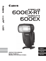
SPEEDLITE
600EX-RT
600EX
SPEED LITE
at
o.
o·
~~
English
INSTRUCTION MANUAL
MODE D’EMPLOI
MANUAL DE INSTRUCCIONES
Français
Español
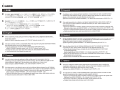
Introduction
The Canon Speedlite 600EX-RT/600EX is a high-output, multi-feature
flash unit for Canon EOS cameras, compat ble with E-TTL II, E-TTL and
TTL autoflash and external flash metering systems. The Speedlite can
be used as an on-camera flash that attaches to the hot shoe of the
camera (normal shooting), and as a master unit or slave unit during
wireless shooting. In addition to these three functions, the Speedlite
also has dust and water resistance equivalent to EOS-1D series
cameras.
Note that the 600EX-RT is equipped with a wireless flash shooting
function that uses either radio transmission or optical transmission. The
600EX is equipped with a wireless flash shooting function that uses
optical transmission only.
Read this instruction manual while also referring to your
camera’s instruction manual.
Before using the Speedlite, read this instruction manual and your
camera’s instruction manual to familiarize yourself with the Speedlite
operations.
Using the Speedlite with a Camera
Using with an EOS digital camera (Type-A camera)
• You can use the Speedlite for easy autoflash shooting in the same
way as a camera’s built-in flash.
Using with an EOS film camera
• When using with an EOS film camera compatible with E-TTL II
and E-TTL autoflash systems (Type-A camera), you can use the
Speedlite for easy autoflash shooting in the same way as a
camera’s built-in flash.
• When using the Speedlite with an EOS film camera compatible
with TTL autoflash system (Type-B camera), see page 116.
* This instruction manual assumes that the Speedlite is used with an
Type-A camera.
2
Chapters
Introduction
1
Getting Started and Basic Operations
2
Advanced Flash Shooting
3
Setting Flash Functions with Camera Operations
4
Wireless Flash Shooting: Radio Transmission
5
Wireless Flash Shooting: Optical Transmission
6
Customizing the Speedlite
7
Reference
2
13
Flash preparations and basic flash shooting
21
Advanced shooting using the flash shooting functions
41
Setting the flash functions from the camera’s menu screen
47
Wireless flash shooting with radio transmission
75
Wireless flash shooting with optical transmission
91
Customizing with Custom Functions and Personal Functions
103
System map, FAQ, use with a type-B camera
When using a Speedlite 600EX, which does not have a radio
transmission function, wireless shooting described in Chapter 4 is not
available. To shoot with wireless flash, see Chapter 5.
3
Contents
Introduction
2
Chapters ...................................................................................................3
Nomenclature............................................................................................6
Conventions Used in this Manual ...........................................................12
1
Getting Started and Basic Operations
13
Installing the Batteries.............................................................................14
Attaching and Detaching the Flash .........................................................15
Turning on the Power..............................................................................16
Fully Automatic Flash Shooting ..............................................................18
Using E-TTL II and E-TTL Autoflash in the Shooting Modes ..................19
2
Advanced Flash Shooting
21
f Flash Exposure Compensation..........................................................22
g FEB ...................................................................................................23
7: FE Lock...........................................................................................24
c High-speed Sync ................................................................................25
r Second-curtain Sync ........................................................................26
Bounce ....................................................................................................27
e: Flash Coverage Setting ..............................................................29
q: Manual Flash.....................................................................................31
?: Stroboscopic Flash....................................................................33
//.: Flash External Metering ...............................................36
Modeling Flash........................................................................................38
Clearing Speedlite Settings.....................................................................38
o Color Filter........................................................................................39
3
Setting Flash Functions with Camera Operations
41
Flash Control from Camera’s Menu Screen............................................42
4
Wireless Flash Shooting: Radio Transmission
47
' Radio Transmission Wireless Flash Shooting....................................48
Wireless Settings ....................................................................................52
a: Fully Automatic Wireless Flash Shooting...................................57
4
Contents
a: Wireless Multiple Flash Shooting with Flash Ratio ................... 61
q: Wireless Multiple Flash Shooting with Manual Flash Output ........... 64
[: Shooting with a Different Flash Mode for Each Group .................... 65
Test Flash and Modeling Flash from a Slave Unit ................................. 67
Remote Release from a Slave Unit ........................................................ 68
Linked Shooting wi h Radio Transmission ............................................. 70
5
Wireless Flash Shooting: Optical Transmission
75
:Optical Transmission Wireless Flash Shooting................................ 76
Wireless Settings ................................................................................... 78
a: Fully Automatic Wireless Flash Shooting.................................. 81
a: Wireless Multiple Flash Shooting with Flash Ratio ................... 85
q: Wireless Multiple Flash Shooting with Manual Flash Output ........... 88
Manual Flash/Stroboscopic Flash Setting on a Slave Unit .................... 89
6
Customizing the Speedlite
91
C / >: Setting Custom and Personal Functions ............................ 92
C: Setting Custom Functions ............................................................ 95
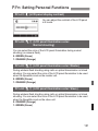
>: Setting Personal Functions ......................................................... 101
7
Reference
103
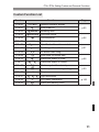
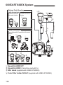
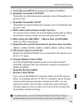
600EX-RT/600EX System.................................................................... 104
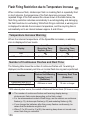
Flash Firing Restriction due to Temperature Increase ......................... 106
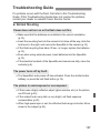
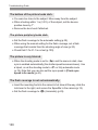
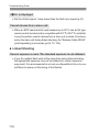
Troubleshooting Guide......................................................................... 107
Specifications ....................................................................................... 112
Using with a Type-B Camera ............................................................... 116
Index .................................................................................................... 120
5
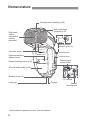
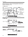
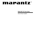
Nomenclature
Catchlight panel (retracted) (p.28)
Built-in wide panel
(retracted) (p 30)
Flash head/
Optical
transmission
wireless
transmitter
Remote release
terminal* (p.68, 70)
Color filter sensor
Terminal cover
Optical transmission
wireless sensor
Terminal cover
External power
source socket
External metering sensor (p 36)
AF-assist beam emitter (p 20)
Mounting foot (p.15)
PC terminal
Locking pin
Contacts
Bracket
mounting hole
* Not provided on Speedlite 600EX. (Do not function.)
6
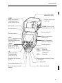
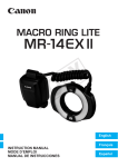
Nomenclature
Color filter holder
attachment (p 39)
<D>
Radio transmission
confirmation lamp*
(p 53, 55, 58, 60, 72)
LCD panel
Function button 2
Bounce angle index
(p.27, 28)
<z > Bounce lock
release button (p 27, 29)
Function button 3
Function button 1
<I >
Wireless button/
Linked shooting button
(p 52, 78/71)
<E >
Flash mode button
(p.18, 31, 33, 36, 37,
58, 64, 65, 82, 88, 89)
<Q >
Flash-ready lamp/
Test flash button
(p.16, 58, 82, 95)
Mounting foot lock lever
(p.15)
Lock-release button (p.15)
Dust- and water-resistant
adapter
Battery compartment
cover (p.14)
Battery compartment
cover lock lever (p.14)
Function button 4
Power switch (p.16)
<K >
: Power on
<a> : Button/dial lock
(Power on)
<J > : Power off
Flash exposure confirmation lamp
(p.18, 58, 82)
<9 > Select Dial
<8 > Select/Set button
7
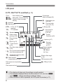
Nomenclature
LCD panel
E-TTL II/E-TTL/TTL autoflash (p.19)
e
N
O
: Zoom display (p.29)
: Wide panel + bounce warning
: Outside of flash coverage
warning
L : Automatic
d : Manual (p 29)
a : E-TTL I /E-TTL
autoflash
b : TTL autoflash
Focal length
(flash coverage/p.29)
c
: High-speed sync
(p 25, 44)
r : Second-curtain
sync (p 26, 44)
0 : Beep (p.99)
j
k
: Standard
S : Auto zoom for
sensor size
(p 20, 98)
: Guide number
priority (p.100)
u : Custom
Functions (p 95)
l
: Even coverage
(p.100)
v : Aperture (p.37)
m:
n:
Bounce (p.27)
o:
Color filter holder attached
(p 39)
l:
Use of commercially-available
color filters warning (p.40)
t
7° down bounce
(p 29)
: Temperature increase (flash
restriction/p.106)
f : Flash exposure
compensation (p 22, 44)
Flash exposure compensation
amount
T : Personal
Functions
(p.101)
Distance indicator
display (p.95)
R : Meters
@ : Feet
Effective flash range
(p.18)
FEB sequence (p.96)
g : FEB (p.23, 44)
Flash exposure level
The display will show only the settings currently applied.
The functions displayed above function buttons 1 to 4, such as <[>
and <@>, change according to settings’ status.
When a button or dial is operated, the LCD panel illuminates (p.17).
8
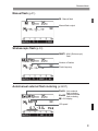
Nomenclature
Manual flash (p.31)
q : Manual flash
Manual flash output
Stroboscopic flash (p.33)
? : Multi (Stroboscopic)
flash
Number of flashes
Flash frequency
Auto/manual external flash metering (p.36/37)
/ : Auto external
flash metering
. : Manual external
flash metering
- : ISO display
ISO speed
9
Nomenclature
Radio transmission wireless shooting/optical transmission
wireless shooting (p.47/75)
Master unit
k : Sync speed warning
M : Master
(radio transmission)
, : Flash ratio
'
Flash mode
[ : Group flash
(radio
transmission)
g: Master flash
d
firing ON
: Master flash
firing OFF
: Radio transmission
wireless shooting
:
: Optical transmission
wireless shooting
: Channel
*
) : Channel automatic
setting (radio
transmission)
Q : Slave flash ready
(radio transmission)
Firing group
Flash ratio
Slave unit
h : Slave icon
x : Slave
:
Individual slave (optical
transmission)
Linked shooting (p.70)
:
Linked shooting
x : Slave
M : Master
10
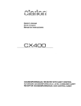
Nomenclature
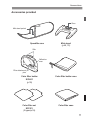
Accessories provided
Shoe
Mini stand pocket
Speedlite case
Mini stand
(p.48, 76)
Slits
Reflection
area
Filter attachment
pins
Color filter holder
SCH-E1
(p.39)
Color filter holder case
Color filter set
SCF-E1
(2 types/p.39)
Color filter case
11
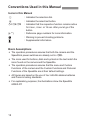
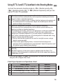
Conventions Used in this Manual
Icons in this Manual
9
: Indicates the selection dial.
8
: Indicates the select/set button.
3/1/2
: Indicates that the respective function remains active
for 4 sec., 6 sec. or 16 sec. after you let go of the
button.
(p.**)
: Reference page numbers for more information.
: Warning to prevent shooting problems.
: Supplemental information.
Basic Assumptions
The operation procedures assume that both the camera and the
Speedlite’s power switches are already set to <K>.
The icons used for buttons, dials and symbols in the text match the
icons found on the camera and the Speedlite.
The operation procedures assume that the menu and Custom
Functions of the camera and the Custom Functions and Personal
Functions of the Speedlite are at their default settings.
All figures are based on the use of four AA/LR6 alkaline batteries
and Canon’s testing standards.
For explanatory purposes, the illustrations show the Speedlite
600EX-RT.
12
1
Getting Started and
Basic Operations
This chapter describes the preparations before starting
flash shooting and the basic shooting operations.
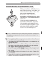
Cautions for firing continuous flashes
To avoid degrading and damaging the flash head
due to overheating, do not fire more than 20
continuous flashes. After 20 continuous flashes,
allow a rest time of at least 10 min.
If you fire more than 20 continuous flashes, and
then fire the flash again repeatedly in short
intervals, the safety function may activate and
restrict flash firing. While flash firing is restricted,
the recycling time is automatically set to an interval
between approx. 8 and 20 sec. If this happens,
allow a rest time of at least 15 min.
For details, see “Flash Firing Restriction due to
Temperature Increase” on page 106.
13
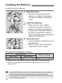
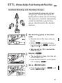
Installing the Batteries
Install four AA/LR6 batteries.
1
Open the cover.
Slide the lock lever to the left as
shown in ", slide the cover down,
and open the battery compartment
cover.
the batteries.
2 Install
Make sure the + and – battery
contacts are correctly oriented as
shown in the battery compartment.
The grooves on the side surfaces of
the battery compartment indicate –.
This is convenient when replacing the
batteries in a dark place.
the cover.
3 Close
Close the battery compartment cover
and slide it up.
X When it clicks in place, the battery
compartment cover is locked.
Recycling Time and Number of Flashes
Recycling Time
Quick Flash
Normal Flash
Approx. 0.1 to 3.3 sec.
Approx. 0.1 to 5.5 sec.
Number of Flashes
Approx. 100 to 700 flashes
Based on new AA/LR6 alkaline batteries and Canon’s testing standards.
The Quick Flash function enables flash shooting before the flash is fully
charged (p.16).
Using AA/LR6 batteries other than the alkaline type may cause improper
battery contact due to the irregular shape of the battery contacts.
If you change the batteries after firing flashes continuously, be aware that
the batteries might be hot.
14
Attaching and Detaching the Flash
When <!> is displayed, replace the batteries with new ones.
Use a new set of four batteries of the same brand. When replacing the
batteries, replace all four at one time.
AA/LR6 rechargeable Ni-MH or lithium batteries can also be used.
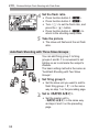
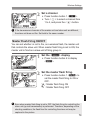
Attaching and Detaching the Flash
1
Attach the Speedlite.
Slip the Speedlite’s mounting foot all
the way into the camera’s hot shoe.
the Speedlite.
2 Secure
On the mounting foot, slide the lock
lever to the right.
X When the lock lever clicks in place, it
will be locked.
the Speedlite.
3 Detach
While pressing the lock-release
button, slide the lock lever to the left
and detach the Speedlite.
Before attaching or detaching the Speedlite, be sure to turn off the
Speedlite.
15
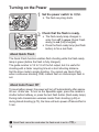
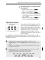
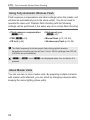
Turning on the Power
1
Set the power switch to <K>.
X The flash recycling starts.
that the flash is ready.
2 Check
The flash-ready lamp changes in
order from off to green (Quick Flash
ready) to red (fully charged).
Press the flash-ready lamp (test flash
button) to fire a test flash.
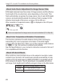
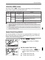
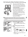
About Quick Flash
The Quick Flash function enables flash shooting while the flash-ready
lamp is green (before the flash is fully charged).
The guide number is 1/2 to 1/6 of the full output, but it is useful for
shooting with a faster recycling time at a short shooting distance.
Set the drive mode to single shooting. You cannot use Quick Flash
when continuous shooting, FEB, manual flash or stroboscopic flash is
set.
About Auto Power Off
To save battery power, the power will turn off automatically after approx.
90 sec. of idle use. To turn on the Speedlite again, press the camera’s
shutter button halfway, or press the test flash button (flash-ready lamp).
During radio transmission wireless master flash shooting (p.59) or
during linked shooting (p.73), the time until auto power off takes effect is
5 min.
Quick Flash cannot be used when the flash mode is set to <b>.
16
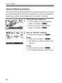
Turning on the Power
About the Lock Function
By setting the power switch to <a>, you can disable flash’s button
and dial operations. Use this to prevent the flash function settings from
being accidentally changed after you set them.
If you operate a button or dial, <LOCKED> is displayed on the LCD
panel (the functions displayed above function buttons 1 to 4, such as
<[> and <@>, are not displayed).
About the LCD Panel Illumination
When a button or dial is operated, the LCD panel illuminates for 12 sec.
When setting a function, the illumination continues until the setting is
complete.
During normal flash shooting, wireless master flash shooting and
master linked shooting, the LCD panel illuminates in green. If the
Speedlite is a slave unit, it illuminates in orange.
You cannot use the test flash while the camera’s 3/1/2 timer is
operating.
The flash settings are stored even when the power is turned off. To retain
the settings when replacing the batteries, replace the batteries within
1 min. of turning off the power switch and removing the batteries.
When the temperature of the flash head has risen due to continuous flash
firing, the time until auto power off takes effect may increase.
You can fire a test flash while the power switch is set to the <a>
position. Also, when a button or dial is operated, the LCD panel
illuminates.
You can set a beep to sound when the Speedlite is fully charged (C.Fn20/p.99).
You can enable the (Quick) flash to fire when the flash-ready lamp is lit
green during continuous shoo ing (C.Fn-06/p.97).
Auto power off can be disabled (C.Fn-01/p.95).
You can change the duration of the LCD panel illumination (C.Fn-22/
p.100).
You can change the color of the LCD panel illumination (P.Fn-02 to 04/
p.101).
17
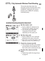
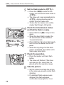
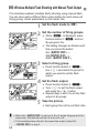
Fully Automatic Flash Shooting
When you set the camera’s shooting mode to <V> (Program AE) or Full
Auto, you can shoot in E-TTL II/E-TTL fully automatic flash mode.
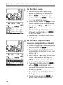
1
Set the flash mode to <a>.
Press the <E> button and set to
<a>.
Check that <M> or
<x> is not displayed.
the subject.
2 Focus
Press the shutter button halfway to
focus.
X The shutter speed and aperture are
displayed in the viewfinder.
Check that <Q> is lit in the viewfinder.
the picture.
3 TakeCheck
that the subject is in the
effective flash range.
When you press the shutter button
completely, the flash will fire and the
picture will be taken.
X If a standard flash exposure was
obtained, the flash exposure
confirmation lamp lights for 3 sec.
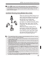
Even when attached to a camera that supports E-TTL II autoflash
system, <a> is displayed on the LCD panel.
If the flash exposure confirmation lamp does not light or if the subject is
dark (underexposed) when you check the image on the camera’s LCD
monitor, move closer to the subject and shoot again. You can also
increase the ISO speed when using a digital camera.
“Full Auto” refers to <A>, <1>, and <C> shooting modes.
18
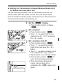
Using E-TTL II and E-TTL Autoflash in the Shooting Modes
Just set the camera’s shooting mode to <X> (Shutter-priority AE),
<W> (Aperture-priority AE), or <q> (Manual exposure) and you can
use E-TTL II/E-TTL autoflash.
Select this mode when you want to set the shutter speed manually.
The camera will then automatically set the aperture matching the shutter
speed to obtain a standard exposure.
X
If the aperture display blinks, it means that the background exposure will
be underexposed or overexposed. Adjust the shutter speed until the
aperture display stops blinking.
Select this mode when you want to set the aperture manually.
The camera will then automatically set the shutter speed matching he
aperture to obtain a standard exposure.
If the background is dark, such as in a night scene, a slow sync speed will
be used to obtain a standard exposure of both the main subject and
background. Standard exposure of he main subject is obtained with the
W flash, while a standard exposure of the background is obtained with a long
exposure using a slow shutter speed.
Since a slow shutter speed will be used for low-light scenes, using a
tripod is recommended.
If the shutter speed display blinks, it means that the background
exposure will be underexposed or overexposed. Adjust the aperture until
the shutter speed display stops blinking.
Select this mode if you want to set both the shutter speed and aperture
manually.
q Standard exposure of the main subject is obtained with the flash. The
exposure of the background is obtained with the shutter speed and aperture
combination you set.
If you use the <Z> or <Y> shooting mode, the result will be the same as
using the <V> (Program AE) mode.
Flash Sync Speeds and Apertures Used
Shutter Speed
Aperture
V
Set automatically (1/X sec. - 1/60 sec.)
Automatic
X
Set manually (1/X sec. - 30 sec.)
Automatic
W
Set automatically (1/X sec. - 30 sec.)
Manual
q
Set manually (1/X sec. - 30 sec., Bulb)
Manual
1/X sec. is the camera’s maximum flash sync speed.
19
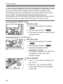
Using E-TTL II and E-TTL Autoflash in the Shooting Modes
About Auto Zoom Adjustment to Image Sensor Size
EOS digital cameras have three sizes of image sensors, and the effective
focal length of the mounted lens varies depending on the model. This
flash automatically recognizes the image sensor size of each EOS digital
camera, and automatically adjusts the optimum flash coverage for the
effective focal length of the lens in a range of 20 to 200 mm.
When mounted on a supported camera, <S> is displayed on the LCD panel.
Auto zoom adjustment for image sensor size can be disabled (C.Fn-09/p 98).
About Color Temperature Information Transmission
This function optimizes the white balance during flash shooting by
transmitting the color temperature information to the EOS digital
camera when the flash fires. When you set the camera’s white balance
to <A> or <Q>, the function is enabled automatically.
See the Specifications in your camera’s instruction manual to find out if
it is compatible with this function.
About AF-Assist Beam
When autofocus cannot achieve focus on the subject in low-light or when
contrast is low, the built-in AF-assist beam activates automatically to help
autofocus.The AF-assist beam in 600EX-RT/600EX is compatible with all
EOS cameras’ AF points. The AF-assist beam is compatible with 28mm
and longer focal lengths and its effective range is shown in the table below.
20
Position
Effective Range (Approx. m/ft.)
Center
0.6 / 2.0 to 10 / 32.8
Periphery
0.6 / 2.0 to 5 / 16.4
2
Advanced Flash
Shooting
This chapter describes advanced shooting operations
using the flash functions.
When the camera’s shooting mode is set to a fully automatic
mode or an Image Zone mode, the operations other than
“Bounce” (p.27, 29), “Wide Panel” (p.30) and “Color Filters”
(p.39) in this chapter are not available. Set the camera’s
shooting mode to V/X/W/q/
5(Creative Zone mode) to
enable all the operations in this chapter.
21
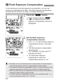
f Flash Exposure Compensation
In the same way as normal exposure compensation, you can set
exposure compensation for flash. The flash exposure compensation
amount can be set up to ±3 stops in 1/3-stop increments.
1
Press the <@> button.
Press function button 2 <@>.
X <f> is displayed and the flash
exposure compensation amount is
highlighted.
the flash exposure
2 Set
compensation amount.
Turn <9> to set the flash exposure
compensation amount, and press
<8>.
X The flash exposure compensation
amount is set.
“0.3” indicates 1/3 stops and “0.7”
indicates 2/3 stops.
To cancel flash exposure
compensation, return the
compensation amount to “±0”.
Generally, set an increased exposure compensation for bright subjects
and set a decreased exposure compensation for dark subjects.
If the camera’s exposure compensation is set to 1/2-stop increments, flash
exposure compensa ion will be up to ±3 stops in 1/2-stop increments.
When the flash exposure compensation is set on both the flash and the
camera, the flash setting is given priority.
The flash exposure compensation amount can be set directly with <9>
without pressing the button (C.Fn-13/p.99).
22
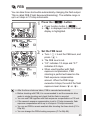
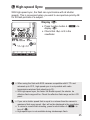
g FEB
You can take three shots while automatically changing the flash output.
This is called FEB (Flash Exposure Bracketing). The settable range is
up to ±3 stops in 1/3-stop increments.
1
Press the <E> button.
Press function button 3 <E>.
X <g> is displayed and the FEB level
display is highlighted.
the FEB level.
2 SetTurn
<9> to set the FEB level, and
press <8>.
X The FEB level is set.
“0.3” indicates 1/3 stops and “0.7”
indicates 2/3 stops.
When used together with flash
exposure compensation, FEB
shooting is performed based on the
flash exposure compensation
amount. When the FEB range
exceeds ±3 stops, the end of the flash
exposure level shows <I> or <J>.
After the three shots are taken, FEB is canceled automatically.
Before shooting with FEB, it is recommended to set the camera’s drive
mode to single shooting and check that the flash is recycled.
You can use FEB together with flash exposure compensation or FE lock.
If the camera’s exposure compensation is set to 1/2-stop increments, flash
exposure compensation will be up to ±3 stops in 1/2-stop increments.
You can set FEB to remain enabled after shooting the three shots (C.Fn03/p.96).
You can change the FEB shooting sequence (C.Fn-04/p 96).
23
7: FE Lock
FE (Flash Exposure) lock locks the correct flash exposure setting for
any part of the scene.
While <a> is displayed on the LCD panel, press the camera’s
<B> button. On cameras without a <B> button, press the <7>
or <P> (AE lock) button.
1
Focus the subject.
the <B> button. (2)
2 Press
Aim the center of the viewfinder over
the subject and press the <B>
button.
X The Speedlite fires a preflash, and
the flash output required for the
subject is retained in the memory.
X “FEL” will be displayed in the
viewfinder for 0.5 sec.
Each time you press the <B>
button, a preflash will be fired and the
new flash output required at that time
is retained in the memory.
If a correct exposure cannot be obtained when FE lock is performed, <Q>
blinks in the viewfinder. Move closer to the subject, open the aperture,
and perform FE lock again. You can also increase the ISO speed and
perform FE lock again when using a digital camera.
If the target subject is too small in the viewfinder, FE lock might not be
very effective.
24
c High-speed Sync
With high-speed sync, the flash can synchronize with all shutter
speeds. This is convenient when you want to use aperture-priority AE
for fill-flash portraits of a subject.
Display <c>.
Press function button 4 <Y> to
display <c>.
Check that <F> is lit in the
viewfinder.
When using the flash with EOS cameras compatible with E-TTL and
released up to 2011, high-speed sync is not possible with radio
transmission wireless flash shooting (p.51).
With high-speed sync, the faster the shutter speed, the shorter he
effective flash range will be. Check the effective flash range on the LCD
panel.
If you set a shutter speed that is equal to or slower than the camera’s
maximum flash sync speed, <F> will not be displayed in the viewfinder.
To return to normal flash shooting, press function button 4 <Y> to
turn off <c>.
High-speed sync is not available during stroboscopic flash.
25
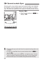
r Second-curtain Sync
Shooting with a slow shutter speed and second-curtain sync captures
the trajectory of moving light sources, such as car lights, in a natural
way. The flash fires right before the exposure finishes (shutter closes).
Display <r>.
Press function button 4 <Y> to
display <r>.
Second-curtain sync works well when the camera’s shooting mode is set
to “buLb”.
To return to normal flash shoo ing, press function button 4 <Y> to
turn off <r>.
When the flash mode is set to <a>, the flash fires twice. This first
flash is a preflash to determine the flash output. It is not a malfunction.
Second-curtain sync is not available during wireless flash shooting.
26
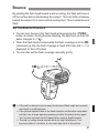
Bounce
By pointing the flash head toward a wall or ceiling, the flash will bounce
off the surface before illuminating the subject. This can soften shadows
behind the subject for a more natural-looking shot. This is called bounce
flash.
Set the Bounce Direction
You can turn (bounce) the flash head while pressing the <z>
button as shown. During bounce shooting, the flash icon on the LCD
panel changes to <m>.
When the flash head is turned while the flash coverage is set to <L>
(automatic) (p.29), the flash coverage is fixed at 50 mm and <---> is
displayed on the LCD panel.
You can also set the flash coverage manually (p.29).
If the wall or ceiling is too far away, the bounced flash might be too weak
and result in underexposure.
If the picture appears dark or the flash exposure confirmation lamp does
not light, use a larger aperture opening (smaller f/number) and try again.
You can also increase the ISO speed when using a digital camera.
The wall or ceiling should be plain white for high reflectance. If he
bounce surface is not white, a color cast may result in the picture.
27
Bounce
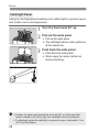
Catchlight Panel
Using the catchlight panel enables you to reflect light in a person’s eyes
and create a more vivid expression.
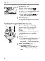
1 Turn the flash head 90° up.
wide panel.
2 PullPulloutupthe
the wide panel.
X The catchlight panel is also pulled up
at the same time.
back the wide panel.
3 Push
Push back the wide panel.
Shoot using the same method as
bounce shooting.
Position the flash head towards the front and 90° up. When the flash
head is rotated to the left or right, the catchlight is not very effective.
To effectively obtain the catchlight in a person’s eyes, shoot within 1.5 m
(4.9 ft.) of the subject.
28
e: Flash Coverage Setting
n Short Distance Flash Shooting
When you position the flash head down
by 7° while pressing the <z>
button, you can shoot subjects at a short
distance in a range of approx. 0.5 to 2 m
(1.6 to 6.6 ft.).
When the flash head is positioned down
by 7°, the flash icon on the LCD panel
changes to <n>.
e: Flash Coverage Setting
“Automatic” and “Manual” settings are available as the flash coverage
settings. In the auto setting, the flash coverage is automatically adjusted
according to the focal length of the shooting lens. With the manual
setting, you can set any flash coverage in a range of 20 to 200 mm.
1
Press the <[> button.
Press function button 1 <[>.
X The flash coverage value is
highlighted.
the flash coverage.
2 SetTurn
<9> to set the flash coverage,
and press <8>.
<L> indicates the automatic setting
and <d> indicates the manual
setting.
29
e: Flash Coverage Setting
When the flash coverage is set to manual, set a flash coverage that is
wider than the angle of view you are shooting, to prevent he periphery of
the picture from being darker.
When a lens wi h a focal length inferior to 20 mm is mounted, the
<O> warning is displayed on the LCD panel. When using a camera
with a smaller image sensor size than full-frame, the <O> warning
is displayed when the actual shooting angle of view is wider than the
angle of view of the 20 mm lens.
When shooting with the camera and Speedlite’s PC terminal connected
by a commercially-available sync cord, set the flash coverage manually.
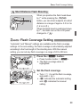
Wide Panel
When you use the flash’s built-in wide panel together, you can perform
flash shooting with ultra-wide angle lenses up to 14 mm.
1
Pull out the wide panel.
Pull out the wide panel.
2 Push back the catchlight panel.
EF15mm f/2.8 Fisheye and EF8-15mm f/4L Fisheye USM angles of view
are not supported.
You cannot set the flash coverage while using the wide panel.
Since underexposure may occur, the <N> warning is displayed on
the LCD panel when using the wide panel wi h bounce shooting.
Pull out the wide panel gently. Using excessive force may detach the
wide panel.
30
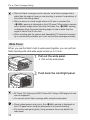
q: Manual Flash
You can set the flash output from 1/128 power to 1/1 full output in 1/3stop increments.
Use a hand-held flash meter to determine the required flash output to
obtain a correct flash exposure. Setting the camera’s shooting mode to
<W> or <q> is recommended.
1
Set the flash mode to <q>.
Press the <E> button and set to
<q>.
the flash output.
2 SetPress
function button 2 <@>.
X The flash output level is highlighted.
Turn <9> to set the flash output,
and press the <8> button.
When you press the camera’s shutter
button halfway, the indication of
shooting distance and the aperture
setting are displayed.
31
q: Manual Flash
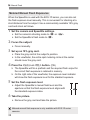
Metered Manual Flash Exposures
When the Speedlite is used with the EOS-1D series, you can also set
the flash exposure level manually. This is convenient for shooting at a
short distance from the subject. Use a commercially available 18% gray
card and shoot as follows.
1
Set the camera and Speedlite settings.
Set the camera’s shooting mode to <q> or <W>.
Set the Speedlite’s flash mode to <q>.
2 Focus the subject.
Focus manually.
3 Set up an 18% gray card.
Place the gray card at the subject’s position.
In the viewfinder, the entire spot metering circle at the center
should cover the gray card.
4 Press the <B> or <7> button. (2)
X The Speedlite will fire a preflash and the required flash output for
the correct flash exposure is retained in memory.
X On the right side of the viewfinder, the exposure level indicator
will show the flash exposure level for the standard exposure.
5 Set the flash exposure level.
Adjust the Speedlite’s manual flash level and the
aperture so that the flash exposure level aligns with
the standard exposure index.
6 Take the picture.
Remove the gray card and take the picture.
Metered manual flash exposure is only available with EOS-1D series
cameras.
32
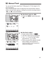
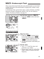
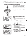
?: Stroboscopic Flash
When using stroboscopic flash with a slow shutter speed, you can shoot
multiple successive movements within a single picture, similar to stopmotion pictures.
In stroboscopic flash, set the flash output, number of flashes, and flash
frequency (number of flashes per second = Hz). For the maximum
number of continuous flashes, see page 35.
1
Set the flash mode to <?>.
Press the <E> button and set to
<?>.
an item.
2 Select
Press the <@> function button
for the flash output, press <Q>
for the number of flashes, and press
<G> for the flash frequency.
X You can set the item of the button you
pressed.
the value.
3 SetTurn
<9> to set the value, and
press the <8> button.
Repeat steps 2 and 3 to set the flash
output, number of flashes and flash
frequency.
33
?: Stroboscopic Flash
Calculating the Shutter Speed
In stroboscopic flash, to ensure that the shutter stays open until the end
of the continuous flashes, set the camera with a shutter speed
calculated with the following equation.
Number of flashes ÷ flash frequency = shutter speed
For example, if the number of flashes is set to 10 (times) and flash
frequency to 5 (Hz), set the shutter speed to 2 sec. or longer.
To avoid degrading and damaging the flash head due to overheating, do
not shoot repeatedly with stroboscopic flash more han 10 times. After
shooting 10 times, allow a rest time of at least 15 min.
If you shoot repeatedly more than 10 times, the safety function may
ac ivate and restrict the flash firing. If this happens, allow a rest time of at
least 15 min.
Stroboscopic flash is most effective when combining a highly reflective
subject with a dark background.
Using a tripod, remote switch and external power source is
recommended.
Stroboscopic flash is not possible with 1/1 power or 1/2 power flash.
Stroboscopic flash is also possible when the camera’s shooting mode is
set to “buLb”.
When the number of flashes is displayed as “---”, flashes are fired
continuously until the shutter closes or he charge runs out. The
maximum number of continuous flashes is shown in the table on he
following page.
34
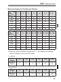
?: Stroboscopic Flash
Maximum Number of Continuous Flashes
Hz
1
2
3
4
5
6-7
8-9
1/4
7
6
5
4
4
3
3
1/8
14
14
12
10
8
6
5
1/16
30
30
30
20
20
20
10
1/32
60
60
60
50
50
40
30
1/64
90
90
90
80
80
70
60
1/128
100
100
100
100
100
90
80
10
11
12 - 14
15 - 19
20 - 50
1/4
2
2
2
2
2
2
2
1/8
4
4
4
4
4
4
4
1/16
8
8
8
8
8
8
8
1/32
20
20
20
18
16
12
10
1/64
50
40
40
35
30
20
15
1/128
70
70
60
50
40
40
30
Flash
Output
Hz
Flash
Output
60 - 199 250 - 500
When the number of flashes is displayed as “---” (bar display), the maximum
number of flashes is as shown in the tables.
1 to 199 Hz
Flash
Output
1/4
1/8
1/16
1/32
1/64
1/128
Number of
Flashes
2
4
8
12
20
40
Flash
Output
1/4
1/8
1/16
1/32
1/64
1/128
Number of
Flashes
2
4
8
10
15
30
250 to 500 Hz
35
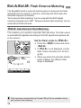
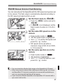
//.: Flash External Metering
The Speedlite’s built-in external metering sensor measures the flash
reflected from the subject in real time, and stops the flash when the
standard exposure is reached.
“Auto external flash metering” can be used with the EOS digital
cameras released since 2007. “Manual external flash metering” can be
used with all EOS cameras.
/: Auto External Flash Metering
This enables you to perform automatic flash shooting. The flash output
is automatically adjusted according to the ISO speed and aperture set
in the camera.
Set the flash mode to </>.
Press the <E> button and set to
</>.
If </> is not displayed, set the
flash Custom Function to C.Fn-05-2
(p.96).
When you press the camera’s shutter
button halfway, the effective flash
range is displayed.
Flash exposure compensation (p.22) and FEB (p.23) are available during
auto external flash metering.
36
//.: Flash External Metering
.: Manual External Flash Metering
You can manually set the Speedlite with the ISO speed and aperture set
in the camera. The flash output is automatically adjusted according to
the ISO speed and aperture that you set.
1
Set the flash mode to <.>.
Press the <E> button and set to
<.>.
If <.> is not displayed, set the
flash Custom Function to C.Fn-05-3
(p.96).
the same ISO speed as on the
2 Set
camera.
Press function button 3 <I>.
X The ISO speed value is highlighted.
Turn <9> to set the ISO speed, and
press the <8> button.
ISO speed can be set within a
maximum range of ISO 25 to 51200,
in 1/3 increments.
the same aperture as on the
3 Set
camera.
Press function button 4 <D>.
X The aperture is highlighted.
Turn <9> to set the aperture, and
press the <8> button.
You can check the effective flash range on the Speedlite’s LCD panel.
When using manual external flash metering and shoo ing with he camera
and Speedlite’s PC terminal connected by a commercially-available sync
cord, you can shoot with the flash off the camera.
If you connect a different Speedlite to the Speedlite’s PC terminal with a
sync cord, it will not fire.
37
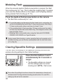
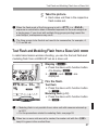
Modeling Flash
When the camera’s depth-of-field preview button is pressed, the flash
fires continuously for 1 sec. This is called the modeling flash. It enables
you to see the shadow effects on the subject, and the lighting balance
during wireless flash shooting (p.47, 75).
Press the depth-of-field preview button on the camera.
X The flash fires continuously for 1 sec.
To avoid degrading and damaging the flash head due to overheating, do
not fire the modeling flash more than 10 times continuously. After firing it
10 times continuously, allow a rest time of at least 10 min.
If the modeling flash is fired more than 10 times continuously, the safety
function may activate and restrict flash firing. If this happens, allow a rest
time of at least 15 min.
Modeling flash is not possible when using the flash with EOS REBEL
2000/QD, EOS 300/QD or a Type-B camera.
During normal flash shooting, or when using the flash as the master unit in
wireless shooting, you can fire the modeling flash with the test flash button
(C.Fn-02/p.95).
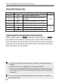
Clearing Speedlite Settings
You can return the settings of the Speedlite shooting functions and
wireless shooting settings to their default settings.
Press function buttons 2 and 3
simultaneously for 2 seconds or
longer.
X The Speedlite settings are cleared
and the settings return to normal
shooting and <a> flash mode.
Even when the settings have been cleared, the transmission channel and
wireless radio ID during wireless shooting as well as the C.Fn and P.Fn
settings (p.92) will not be canceled.
38
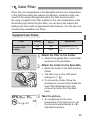
o Color Filter
When the color temperature of the Speedlite and the color temperature
of the light illuminating the subject are different, unnatural colors may
result for the subject background where the flash does not reach.
By using a supplied color filter suitable for the color temperature of the
illuminating light while firing the flash, you can shoot the subject and
background colors with an appropriate white balance. You can also use
commercially-available color filters.
Supplied Color Filters
Filter
Tungsten light
(orange)
Density
Compensation
Effect
Low
Low
High
High
1
Application
Compensates for the
effect of a tungsten light
bulb
Attach the filter to the holder.
Attach the supplied filter to the holder
as shown in the illustration.
the holder to the Speedlite.
2 Attach
Attach the holder to the flash head as
shown.
The flash icon on the LCD panel
changes to <o>.
To remove the holder, follow the
procedure in reverse order. Raise the
lower filter attachment pins and
remove the holder from the flash
head.
the picture.
3 TakeTo compensate
for the color
temperature of the light source, set
the camera’s white balance to <Q>
and take the picture.
39
o Color Filter
With EOS digital cameras released
since 2012, you can also set the white
balance to <A> for shooting.
Check the resulting image, and
perform WB compensation as required.
Commercially-available Color Filters
When using a commercially-available 75 x 75 mm filter (3 in. x 3 in.), disable the
automatic filter detection function (P.Fn-05-1/p.102). If you use a commerciallyavailable color filter with P.Fn-05-0 set, <l> may be displayed. Shoot a
picture with the filter attached in the actual shooting environment and set it for
manual white balance. Take the picture with the white balance set to <c>.
The flash guide number decreases when you use a color filter. When
performing manual flash or stroboscopic flash with one of the supplied
color filters, set flash exposure compensation according to the following
guidelines.
[Low] Orange:+1/3 stop, [High] Orange: +1 stop
When P.Fn-05-0 is set, if you use a commercially-available color filter
whose color is close to the supplied color filters, <l> may not be
displayed.
As shown in step 1 on the preceding page, attach he filter all the way to
the position of he filter attachment pins on the holder. If the filter is not
attached correctly, it may not be detected.
When using a filter, the use of full power or continuous flashes is not
recommended. The filter may deform due to the heat of the flash.
The denser the color of the filter, the more likely it is to deform due to the
heat of the flash.
With cameras that are not compatible with color temperature information
transmission (p.20), set the white balance to <c> and shoot in the
same way as described in “Commercially-available Color Filters”.
When using a commercially-available coloring filter, you do not need to
set the white balance to <c>.
Attaching the holder does not affect the flash coverage.
Even if the filter deforms due to he heat of the flash, it does not affect its
compensation effect.
Filters are consumable parts. When the supplied filters have worn out or
degraded, purchase new genuine filters.
If dirt or dust adheres to a filter, wipe it off with a soft, dry cloth.
If the color filter sensor (p.6) or the holder reflection area (p.11) is dirty or
dusty, clean it with a blower or similar tool.
40
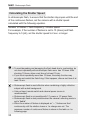
3
Setting Flash Functions
with Camera Operations
This chapter describes how to set the flash functions
from the camera’s menu screen.
When the camera’s shooting mode is set to a fully automatic
mode or an Image Zone mode, the operations in this chapter
are not available. Set the camera’s shooting mode to V/X/
W/q/
5(Creative Zone mode).
41
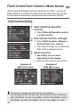
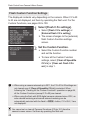
Flash Control from Camera’s Menu Screen
When using EOS digital cameras released since 2007, you can set
flash functions or Custom Functions from the camera’s menu screen.
For the camera operations, see the camera’s instruction manual.
Flash Function Setting
1
Select [External Speedlite
control].
Select [External Speedlite control]
or [Flash control].
[Flash function settings].
2 Select
Select [Flash function settings] or
[External flash func. setting].
X The screen changes to the (external)
flash function settings screen.
the function.
3 SetThe
setting screen varies
depending on the camera.
Select an item and set the function.
Example of
EOS-1D X screen
Example of
EOS 60D screen
The cameras released from 2007 to 2011 are as follows.
EOS-1Ds Mark III, EOS-1D Mark IV/III, EOS 5D Mark II, EOS 7D/60D/50D/
40D, EOS REBEL T3i/600D, EOS REBEL T2i/550D, EOS REBEL T1i/500D,
EOS REBEL XSi/450D, EOS REBEL T3/1100D, EOS REBEL XS/1000D
42
Flash Control from Camera’s Menu Screen
Settings Available in [Flash function settings]
EOS digital cameras released since 2012
When using the flash with cameras such as EOS-1D X, you can set the
functions for “Normal shooting”, “Radio transmission wireless shooting”
or “Optical transmission wireless shooting” in the [Flash function
settings] screen.
EOS digital cameras released from 2007 to 2011
You can set the functions for “Normal shooting” or “Optical transmission
wireless shooting” in the [Flash function setting] screen. To use
“Radio transmission wireless shooting”, set the functions by operating
the flash.
The settable functions are as follows. The available settings vary
depending on the flash mode or wireless function setting.
Function
Flash firing
Enable / Disable
E-TTL II flash metering Evaluative / Average
Flash synchronization speed in Av mode
E-TTL II (autoflash) / Manual flash /
MULTI flash / Auto external flash
Flash mode
metering / Manual external flash
metering / TTL (autoflash)
Shutter
1st curtain / 2nd curtain / Hi-speed
synchronization
Flash exposure compensation
FEB
Zoom (flash coverage)
Wireless functions
Radio transmission wireless /
(setting)
Optical transmission wireless
Clear Speedlite function settings
Reference Page
p.44
p.45
[Flash firing] and [E-TTL II flash metering] are displayed in step 2 or
step 3 on the preceding page (depending on the camera).
When [Flash sync. speed in Av mode] is not displayed, it can be set
with the camera’s Custom Function.
43
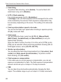
Flash Control from Camera’s Menu Screen
Flash firing
To perform flash shooting, set to [Enable]. To use the flash’s AFassist beam only, set to [Disable].
E-TTL II flash metering
For normal exposures, set it to [Evaluative].
If [Average] is set, the flash exposure will be averaged for the entire
scene metered by the camera. Flash exposure compensation may
be necessary depending on the scene. This setting is for advanced
users.
Flash synchronization speed in Av mode
You can set the flash sync speed when shooting in aperture-priority
AE (Av) mode with flash.
Flash mode
You can select the flash mode from [E-TTL II], [Manual flash],
[MULTI flash], [AutoExtFlash] and [Man.ExtFlash] to suit your
desired flash shooting.
When the flash’s Custom Function C.Fn-05 is set to [1:TTL] (p.96),
[TTL] can be selected. When performing autoflash shooting with an
EOS digital camera, set to [0:E-TTL II/E-TTL].
Shutter synchronization
You can select the flash firing timing/method from [1st curtain], [2nd
curtain] and [High-speed synchronization]. To perform normal
flash shooting, set [1st curtain].
Flash exposure compensation
In the same way as normal exposure compensation, you can set
exposure compensation for flash. The flash exposure compensation
amount can be set up to ±3 stops in 1/3-stop increments.
FEB
You can take three shots while automatically changing the flash
output. The settable range is up to ±3 stops in 1/3-stop increments.
44
Flash Control from Camera’s Menu Screen
Zoom (flash coverage)
You can set the flash coverage for the Speedlite. When [Auto] is
selected, the flash coverage is set automatically according to the
focal length of the lens.
Wireless flash functions (setting)
You can perform wireless flash shooting. Two wireless flash shooting
methods are available; radio transmission and optical transmission.
For details, see Chapter 4 and Chapter 5.
Clear Speedlite (function) settings
You can return the flash settings to their default settings.
When flash exposure compensation is set on the flash, you cannot set flash
exposure compensation in the camera’s menu screen. Note that if both are
set at the same time, the setting on the flash is given priority.
45
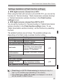
Flash Control from Camera’s Menu Screen
Flash Custom Function Settings
The displayed contents vary depending on the camera. When C.Fn-20
to 23 are not displayed, set them by operating the flash unit. For the
Custom Functions, see pages 95 to 100.
1
Select [Flash C.Fn settings].
Select [Flash C.Fn settings] or
[External flash C.Fn setting].
X The screen changes to the (external)
flash Custom Function settings
screen.
the Custom Function.
2 SetSelect
the Custom Function number
and set the function.
To clear all the Custom Function
settings, select [Clear all Speedlite
C.Fn’s] or [Clear ext. flash C.Fn
set.] in step 1.
When using a camera released up to 2011, the C.Fn-20 to 23 settings are
not cleared even if [Clear all Speedlite C.Fn’s] is selected. When
following the “Clearing All the Custom Functions” operation on page 94,
all the Custom Functions (except C.Fn-00) are cleared.
When using the flash with EOS digital cameras released since 2012, as
auto external metering and manual external metering can be
automatically selected with the flash’s <E> button, C.Fn-05-2, 3 are
not displayed.
You cannot set or clear all Personal Functions (P.Fn/p.101) from the
camera’s menu screen. Set them by operating the flash unit.
46
4
Wireless Flash Shooting:
Radio Transmission
This chapter describes wireless flash shooting using
radio transmission.
For the accessories required for radio transmission
wireless shooting, see the system map (p.104). For
the regions of use, restrictions, and precautions
related to radio transmission, refer to the separate
leaflet.
When using a Speedlite 600EX (without radio
transmission function), the shooting in this chapter is not
available. To shoot with optical transmission wireless
flash, see Chapter 5 (p.75).
When the camera’s shooting mode is set to a fully
automatic mode or an Image Zone mode, the operations
in this chapter are not available. Set the camera’s
shooting mode to V/X/W/q/
5(Creative Zone mode).
The 600EX-RT attached to the camera is called the master
unit, and a 600EX-RT that is wirelessly controlled is called the
slave unit.
You can also wirelessly control the 600EX-RT set as the slave
unit with the Speedlite Transmitter ST-E3-RT (sold
separately). For details on setting the master unit functions,
see the transmitter’s instructions.
47
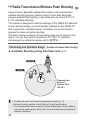
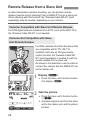
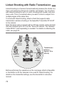
' Radio Transmission Wireless Flash Shooting
Using a Canon Speedlite (master/slave) with a radio transmission
wireless shooting function makes it easy to shoot with advanced
wireless multiple flash lighting, in the same way as normal E-TTL II/
E-TTL autoflash shooting.
The system is designed so that the settings of the 600EX-RT attached
to the camera (master) are automatically reflected on the 600EX-RT
that is wirelessly controlled (slave). Therefore, you do not need to
operate the slave unit while shooting.
The basic relative positions and operating range are as shown in the
figure. You can then perform wireless E-TTL II/E-TTL autoflash
shooting just by setting the master unit to <a>.
Positioning and Operation Range (Example of wireless flash shooting)
Autoflash Shooting Using One Slave Unit (p.57)
M
x
Transmission
distance
Approx. 30 m
(98.4 ft.)
Position the slave unit using the supplied mini stand (p.11).
Before shooting, perform a test flash (p.16) and test shooting.
The transmission distance may be shorter depending on the conditions
such as the positioning of slave units, the surrounding environment and
weather conditions.
48
' Radio Transmission Wireless Flash Shooting
Wireless Multiple Flash Shooting
You can divide the slave units into two or three groups and perform
E-TTL II/E-TTL autoflash shooting while changing the flash ratio
(factor). In addition, you can set and shoot with a different flash mode
for each firing group, for up to 5 groups.
Autoflash Shooting with Two Slave Groups (p.61)
A
B
Autoflash Shooting with Three Slave Groups (p.62)
C
A
B
49
' Radio Transmission Wireless Flash Shooting
Shooting with a Different Flash Mode set for Each Group (p.65)
Auto external
flash metering
Ceiling
E
E-TTL II
A
D
B
C
Manual flash
Manual flash
Manual flash
* The flash mode settings are
indicated only as an example.
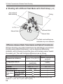
Difference between Radio Transmission and Optical Transmission
Wireless shooting using radio transmission has advantages over wireless
shooting using optical transmission, such as being less affected by
obstacles, and not having to point the slave unit’s wireless sensor toward
the master unit. The main functional differences are as follows.
Function
Transmission distance
Firing group control
Slave unit control
Channel
Wireless radio ID
Operations Test flash firing
from slave
unit
Modeling flash
Radio Transmission
Optical Transmission
Approx. 15 m (49.2 ft.)
Approx. 30 m (98.4 ft.)
(indoors)
Up to 3 groups
Up to 5 groups*1
(A/B/C)
(A/B/C/D/E)
Up to 15 units
No restriction
Auto, Ch. 1 - 15
Ch. 1 - 4
0000 - 9999
–
–
*2
–
–
*3
*1, *2 and *3: Some restrictions apply depending on the camera that you use.
(Refer to *1: p.51, 65; *2: p.67; and *3: p.68.)
50
Release
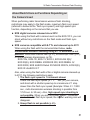
' Radio Transmission Wireless Flash Shooting
About Restrictions on Functions Depending on
the Camera Used
When performing radio transmission wireless flash shooting,
restrictions may apply to the flash mode, maximum flash sync speed
(referred to below as the “flash sync speed”) and high-speed sync
function, depending on the camera that you use.
EOS digital cameras released since 2012
When using the flash with a camera such as the EOS-1D X, you can
shoot without any restrictions on the flash mode and flash sync
speed.
EOS cameras compatible with E-TTL and released up to 2011
When using the flash with the cameras listed below, radio
transmission wireless shooting using E-TTL autoflash is not
possible. Shoot with manual flash (p.31), stroboscopic flash (p.33)
or optical wireless transmission (p.75).
EOS-1Ds, EOS-1D, EOS-1V, EOS-3, EOS ELAN II(E)/
EOS 50(E), EOS REBEL 2000/EOS 300, EOS REBEL G/
EOS 500N, EOS 66/EOS Rebel XS N/EOS 3000 N, EOS IX(E),
EOS IX Lite/EOS IX 7
Also, when using the flash with a film or digital camera released up
to 2011, the following restrictions apply.
1. The flash sync speed is 1 increment slower
Check the flash sync speed (X = 1/*** sec.) of your camera,
and shoot with a shutter speed up to a maximum of 1 stop
slower than the flash sync speed (Example: When X = 1/250
sec., radio transmission wireless shooting is possible from
1/125 sec. to 30 sec.). Also, high-speed sync shooting is
not possible. When you set the shutter speed 1 increment
slower than the flash sync speed, the <k> warning icon will
disappear.
2. Group flash is not possible (p.65).
51
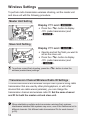
Wireless Settings
To perform radio transmission wireless shooting, set the master unit
and slave unit with the following procedure.
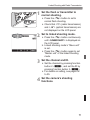
Master Unit Setting
Display <'> and <M>.
Press the <I> button to display
<'> (radio transmission) and
<M>.
Slave Unit Setting
Display <'> and <x>.
Operate and set the flash you want to
set as the slave unit.
Press the <I> button to display
<'> (radio transmission) and
<x>.
To perform normal flash shooting, press the <I> button to clear the
wireless (master/slave) settings.
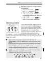
Transmission Channel/Wireless Radio ID Settings
To avoid interference with wireless multiple flash systems using radio
transmission that are used by other photographers, or with other
devices that use radio waves (wireless), you can change the
transmission channel and wireless radio ID. Set the same channel
and ID for both the master unit and slave unit.
When establishing multiple radio transmission wireless flash systems,
interference between flash systems may occur, even if the flashes are set to
different channels. Set different radio transmission IDs for each channel
(p.53).
52
Wireless Settings
Setting the Transmission Channel/Wireless Radio ID of
the Master Unit and Slave Unit
Use the following procedure to set the transmission channels and
wireless radio IDs of the master unit and slave unit. Set the same
channel and ID for both the master unit and slave unit. The procedure is
the same for the master unit and slave unit.
1
Set the <O> display.
Press function button 4 to display
<O>.
a channel.
2 SetPress
function button 1 <C>.
Turn <9> to select “AUTO” or a
channel from Ch. 1 to 15, and press
the <8> button.
a wireless radio ID.
3 SetPress
function button 2 <H>.
Turn <9> to select the position
(digit) to set, and press the <8>
button.
Turn <9> to select a number from 0
to 9, and press the <8> button.
Repeat step 3 to set a 4-digit number.
Press function button 4 <?> to
return to the shooting-ready state.
X When transmission between the
master unit and slave unit is
established, the <D> lamp is lit in
green.
53
Wireless Settings
Scanning the Master Unit Transmission Channels to Set
You can scan the radio reception status and set the master unit’s
transmission channel automatically or manually. When the channel is
set to “AUTO”, the channel with the best reception signal is
automatically set. When setting the channel manually, you can set the
transmission channel again while referring to the scan results.
Scanning while “AUTO” is set
Run the scan.
Press function button 4 to display
<O>.
Press function button 3 <W>.
X The channel is reset to one with a good
reception signal.
Scanning while Ch. 1 to 15 is set
1
Run the scan.
Press function button 4 to display
<O>.
Press function button 3 <W>.
X The radio reception status is
displayed in a graph.
The higher the peak of the channel in
the graph, the better the radio
reception signal.
a channel.
2 SetTurn
<9> to select a channel from
Ch. 1 to 15.
Press the <8> button to set the
channel and return to the shootingready state.
54
Wireless Settings
About the <D> Lamp
The color of the <D> lamp changes depending on the transmission
status of the master unit and the slave unit.
Color
Status
Description
Action
Green
Lit
Transmission
OK
–
Lit
Not connected
Check the channel and ID
Too many units
Master units + slave units =
16 units or less
Red
Blinking
Error
Turn the power off and on again
If the transmission channels of the master unit and slave unit are
different, the slave unit does not fire. Set both to the same number, or set
both to “AUTO”.
If the wireless radio IDs of the master unit and slave unit are different, the
slave unit does not fire.
Master Flash Firing ON/OFF
You can set whether or not to fire, as a wireless flash, the master unit
that controls the slave unit. When master flash firing is set to ON, the
master unit is fired as firing group A.
1
Set the <N> display.
Press function button 4 to display
<N>.
the master flash firing.
2 SetPress
function button 1 <4> to
set the master flash firing to ON or
OFF.
g : Master flash firing ON
d : Master flash firing OFF
55
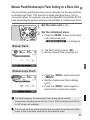
Wireless Settings
About the Memory Function
You can save the wireless settings in the master unit and slave unit, and
recall the settings later. Operate the master unit or slave unit separately
depending on which unit’s settings are to be saved or recalled.
1
Press function button 4.
On the master unit, press function
button 4 to display <P>.
On the slave unit, press function
button 4 to display <O>.
or load the settings.
2 Save
Press function button 3 <L>.
[Save]
Press function button 1 <V>.
X The settings are saved (stored in the
memory).
[Load]
Press function button 2 <J>.
X The settings that were saved are set.
56
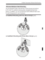
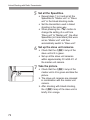
a: Fully Automatic Wireless Flash Shooting
This section describes basic fully
automatic wireless shooting when using
a 600EX-RT attached to the camera
(master) and a 600EX-RT wirelessly
controlled (slave).
Autoflash Shooting Using One Slave Unit
1
Set the master unit.
Set the 600EX-RT attached to the
camera as the master unit (p.52).
You can also use a Speedlite
Transmitter ST-E3-RT (sold
separately) as the master unit.
unit.
2 SetSetthetheslave
600EX-RT to be controlled
wirelessly as the slave unit (p.52).
Set A, B or C as the firing group. The
flash will not fire if it is set to D or E.
the channel and ID.
3 Check
If the channels and IDs of the master
unit and slave unit are different, set
them to the same numbers (p.53, 54).
the camera and the
4 Position
flash.
Position them within the range shown
on page 48.
57
a: Fully Automatic Wireless Flash Shooting
the flash mode to <a>.
5 SetPress
the <E> button on the
master unit and set the flash mode to
<a>.
The slave unit is set automatically to
<a> during shooting via the
control from the master unit.
To also fire the master unit, set the
master flash firing to ON (p.55).
the transmission status
6 Check
and that the flash is ready.
Check that the <D> lamp is lit in
green.
When the slave flash is ready, the
AF-assist beam emitter blinks at
1-second intervals.
Check that the <Q> slave flash-ready
icon is lit on the master unit’s LCD
panel.
When the recycling of all the flash
units is completed, the master unit’s
flash-ready lamp lights.
the operation.
7 Check
Press the master unit’s test flash
button.
X The slave unit flashes. If the slave
unit does not fire, check that it is
placed within the operation range.
picture.
8 TakeSetthe
the camera and take the picture,
in the same way as with normal flash
shooting.
X If a standard flash exposure was
obtained, the flash exposure
confirmation lamp lights for 3 sec.
58
a: Fully Automatic Wireless Flash Shooting
If the <D> lamp is red, radio transmission has not been established.
Check again the transmission channels and wireless radio IDs of the master
unit and slave unit. If you cannot connect with the same settings, turn the
power off and on again.
Autoflash Shooting Using Multiple Slave Units
When you need more flash output or you
want to perform lighting more easily, you
can increase the number of slave units
and fire them as a single flash.
To add slave units, use the same
procedure as “Autoflash Shooting Using
One Slave Unit”. Set A, B or C as the
firing group. The flash will not fire if it is
set to D or E.
When the number of slave units is
increased or master flash firing set to
ON, automatic control is performed to
fire all flashes at the same flash output
and ensure that the total flash output
results in the standard exposure.
The master/slave flash coverage is set automatically to 24 mm. You can
also set he flash coverage manually.
You can press the depth-of-field preview button on the camera to fire the
modeling flash (p.38).
When the Speedlite is set as the master unit, the time until auto power off
takes effect is 5 min.
If the slave unit’s auto power off takes effect, press the master unit’s test
flash button (p.16) to turn on he slave unit. Note that the test flash cannot
be fired while the camera’s metering imer is operating.
The autoflash system (E-TTL II/E-TTL) depends on the camera used and
is set automatically. Note that <a> is displayed on the LCD panel for
both systems.
You can change the time until the slave unit’s auto power off takes effect
(C.Fn-10/p.98).
You can enable a beep to sound when the charge of all the slave units is
complete (C.Fn-20/p.99).
You can set it up so that the AF-assistant beam emitter will not blink when
the slave unit recycling is completed (C.Fn-23/p.100).
59
a: Fully Automatic Wireless Flash Shooting
Using Fully Automatic Wireless Flash
Flash exposure compensation and other settings set on the master unit
will also be automatically set in the slave unit(s). You do not need to
operate the slave unit. Wireless flash shooting with the following
settings can be performed in the same way as in normal flash shooting.
• Flash exposure compensation
(@/p.22)
• High-speed sync
(Y/p.25)
• FEB (E/p.23)
• Manual flash (p.31, 64)
• FE lock (p.24)
• Stroboscopic flash (p.33)
<@>, <Y> and <E> are displayed when func ion button 4 is
pressed.
About Master Units
You can use two or more master units (master units + slave units =
maximum of 16 units). By preparing multiple cameras with master units
attached, you can shoot by changing cameras while keeping the same
lighting (slave units).
Note that when using two or more master units, the color of the <D>
lamp varies depending on the order in which the power was turned on.
The first master (main master) is green and the second and subsequent
masters (sub-masters) are orange.
If he <D> lamp is red, the connection has not been established. After
checking the transmission channel and wireless radio ID, turn the power of
each master unit off, and turn it on.
60
a: Wireless Multiple Flash Shooting with Flash Ratio
Autoflash Shooting with Two Slave Groups
You can divide the slave units into two
firing groups, A and B, and adjust the
lighting balance (flash ratio) for shooting.
The exposure is controlled automatically
so that the total flash output of firing
groups A and B results in the standard
exposure.
B
A
1
Set the firing group of the slave
units.
Operate and set the slave units one
by one.
While <M> is displayed, press
function button 3 <F> and select
<4> or <5>.
Set one unit to <4> and set the
other to <5>.
<N>.
2 Display
The operations in steps 2 to 4 are set
on the master unit.
Press function button 4 on the master
unit to display <N>.
to <%>.
3 SetPress
function button 2 <T> and
set to <%>.
61
a: Wireless Multiple Flash Shooting with Flash Ratio
the flash ratio.
4 SetPress
function button 3 <F>.
Press function button 3 <A>.
Turn <9> to set the flash ratio, and
press the <8> button.
Press function button 4 <?> to
return to the shooting-ready state.
the picture.
5 Take
X The slave unit flashes at the set flash
ratio.
Autoflash Shooting with Three Slave Groups
You can add firing group C to firing
groups A and B. C is convenient to set
lighting so as to eliminate the subject’s
shadow.
The basic setting method is the same as
“Autoflash Shooting with Two Slave
Groups”.
C
B
A
1
Set firing group C.
Set the slave unit you want to add to
flash firing group <6> in the same
way as step 1 on the preceding page.
<^>.
2 SetSetto the
master unit to
<^> in the same way
as steps 2 and 3 on the preceding
page.
62
a: Wireless Multiple Flash Shooting with Flash Ratio
flash exposure compensation
3 Set
as required.
Press function button 3 <F>,
turn <9> and select <6>.
Press function button 3 <B>.
Turn <9> to set the flash exposure
compensation amount, and press the
<8> button.
Press function button 4 <?> to
return to the shooting-ready state.
Slave Group Control
If you need more flash output or wish to
perform more sophisticated lighting, you
can increase the number of slave units.
Simply set an additional slave unit to the
firing group (A, B or C) whose flash
Gr = A Gr = A Gr = A
output you want to increase. You can
increase the number of slave units up to
15 units in total.
For example, if you set a firing group with three slave units to <4>,
the three units are treated and controlled as a single firing group A with
a large flash output.
Firing group A
To fire the three firing groups A, B and C at the same time, set
<^>. With the <%> setting, firing group C does
not fire.
If you shoot with firing group C pointing directly toward the main subject,
overexposure may result.
The flash ratio of 8:1 to 1:1 to 1:8 is equivalent to 3:1 to 1:1 to 1:3 (1/2stop increments) when converted to number of stops.
The details of the flash ratio set ings are as follows.
63
q: Wireless Multiple Flash Shooting with Manual Flash Output
This describes wireless (multiple flash) shooting using manual flash.
You can shoot with a different flash output setting for each slave unit
(firing group). Set all parameters on the master unit.
1 Set the flash mode to <q>.
the number of firing groups.
2 SetWhile
<M> is displayed, press
function button 2 <T> and set
the groups to fire.
The setting changes as follows each
time you press the button:
ALL (_) →
A/B (%) →
A/B/C (]).
a firing group.
3 Select
Press function button 3 <F>,
turn <9> and select the group for
which you want to set the flash
output.
the flash output.
4 SetPress
function button 3 <1>.
Turn <9> to set the flash output,
and press the <8> button.
Repeat steps 3 and 4 to set the flash
output of all groups.
the picture.
5 Take
X Each group fires at the set flash ratio.
When ALL <_> is set, set A, B or C as the firing group for the
slave units. The flash will not fire if it is set to D or E.
To fire multiple slave units wi h the same flash output, select ALL
<_> in step 2.
64
[: Shooting with a Different Flash Mode for Each Group
Ceiling
D
E
C
A
B
When using an EOS digital camera
released since 2012, such as the EOS1D X, you can shoot with a different flash
mode set for each firing group, with up to
5 groups (A/B/C/D/E).
The flash modes that can be set are "
E-TTL II/E-TTL autoflash, # Manual
flash and $ Auto external flash
metering. When the flash mode is " or
$, exposure is controlled to result in
standard exposure for the main subject
as a single group.
This function is for advanced users who
are very knowledgeable and
experienced in lighting.
Wireless flash shooting using the <[> flash mode cannot be performed
with cameras released up to 2011. Shoo ing with up to 3 groups (A/B/C) is
set (p.62).
1
Set the flash mode to <[>.
Press the <E> button on the
master unit and set the flash mode to
<[>.
the firing group of the slave
2 Set
units.
Operate and set the slave units one
by one.
While <M> is displayed, press
function button 3 <F> and select
<4>, <5>, <6>, <!> or
<">.
Set the firing group (A/B/C/D/E) for all
the slave units.
65
[: Shooting with a Different Flash Mode for Each Group
mode.
3 SetSetthetheflash
flash mode of each firing
group by operating the master unit.
While <M> is displayed, press
function button 3 <F> and turn
<9> to select the group.
Press function button 2 <2> and
select the flash mode of the selected
group from <a>, <q> and
</>.
To turn the firing of the selected group
off, press function button 1 <R>
to set it to <OFF>.
Repeat step 3 to set the flash mode
of all groups.
the flash output or flash
4 Set
exposure compensation amount.
While a firing group is selected, press
function button 3 <1>.
Turn <9> to set the flash function
corresponding to the flash mode, and
press <8>.
When using the <q> mode, set the flash
output. When using the <a> or
</> mode, set the flash exposure
compensation amount as required.
If you press function button 2 <@>
when <M> is displayed, flash
exposure compensation can be set for
all the firing groups.
Repeat step 4 to set the flash function
of all groups.
Press function button 4 <?> to
return to the shooting-ready state.
66
Test Flash and Modeling Flash from a Slave Unit
the picture.
5 Take
X Each slave unit fires in the respective
flash modes set.
When the flash mode of the firing group is set to <a> or </>,
exposure is controlled to obtain a standard exposure for the main subject as
a single group. If you shoot with multiple firing groups pointing toward the
main subject, overexposure may result.
The firing groups to be fired do not need to be consecutive; for example, A,
C, E can be set.
Test Flash and Modeling Flash from a Slave Unit
In radio transmission wireless shooting, you can fire the test flash and
modeling flash from a 600EX-RT set as a slave unit.
1
Display <N>.
Press the slave unit’s function button
4 to display <N>.
X <>> and <Z> are
displayed.
the flash.
2 Fire
Test flash
Press the slave unit’s function button
3 <Z>.
Modeling flash (p.38)
Press the slave unit’s function button
2 <>>.
Modeling flash is not possible from a slave unit with cameras released up
to 2011.
For the precautions related to modeling flash, see page 38.
When two or more units are set to master, the master unit with the <D>
lamp lit in green is the one that fires.
67
Remote Release from a Slave Unit
In radio transmission wireless shooting, you can perform remote
release (remote control shooting) from a 600EX-RT set as a slave unit.
When shooting with this function, the “Release Cable SR-N3” (sold
separately) may be needed, depending on your camera.
Cameras Compatible with Slave Unit Remote Release
For EOS digital cameras released since 2012, such as the EOS-1D X,
the “Release Cable SR-N3” is not needed.
Cameras Not Compatible with Slave
Unit Remote Release
For EOS cameras other than the above that
are compatible with E-TTL II/E-TTL
autoflash and have an N3 type remote
control terminal, the “Release Cable SRN3” (sold separately) is needed to perform
remote release from a slave unit.
As shown in the illustration, use the cable to
connect the camera and the 600EX-RT set
as the master unit.
1
Display <N>.
Press the slave unit’s function button
4 to display <N>.
the picture.
2 TakePress
the slave unit’s function button
1 <U>.
X A release signal is sent from the slave
unit to the master unit, and the picture
is taken.
68
Remote Release from a Slave Unit
Connect the release cable while the power of the camera and the
Speedlite is off.
Shooting is not possible when focusing with autofocus fails. Focusing
manually before performing remote release is recommended.
The “Release Cable SR-N3” (sold separately) is for an N3 type remote
control terminal. It cannot be used with cameras equipped with a remote
control terminal other than he N3 type.
Remote release is performed with “Single shooting” regardless of the
camera’s drive mode setting.
When there are two or more master units, remote release is performed
using the master unit with the <D> lamp lit in green.
69
Linked Shooting with Radio Transmission
Linked shooting is a function that automatically releases the shutter of a
slave unit camera by linking it to a master unit camera. You can shoot
with linked shooting for up to 16 units, including both master units and
slave units. This is convenient when you want to shoot a subject from
multiple angles at the same time.
To shoot with linked shooting, attach a flash that supports radio
transmission wireless shooting or the Speedlite Transmitter ST-E3-RT
to the camera.
Note that when using a camera with an N3 type remote control terminal
that was released up to 2011 as the “slave unit camera,” the “Release
Cable SR-N3” (sold separately) is needed. For details on attaching the
cable, see page 68.
Slave unit
camera
Slave unit
camera
Transmission
distance
Approx. 30 m
(98.4 ft.)
Slave unit
camera
Master unit
camera
Slave unit
camera
Before performing the operations on the next page, attach a Speedlite
or transmitter on all the cameras to be used for linked shooting. For
details on the transmitter settings, see the transmitter’s instruction
manual.
70
Linked Shooting with Radio Transmission
1
Set the flash or transmitter to
normal shooting.
Press the <I> button to set to
normal flash shooting.
Check that <'> (radio transmission)
and <:> (optical transmission) are
not displayed on the LCD panel.
to linked shooting mode.
2 SetPress
the <I> button continuously
until <b> is displayed on
the LCD panel.
X Linked shooting mode’s “Slave unit”
is set.
Press the <I> button again to set
“Master unit” of the linked shooting
mode.
and ID.
3 SetSetthethechannel
channel by pressing function
button 2 <C>, and set the ID by
pressing function button 3 <H>.
For details on setting, see pages 52
to 55.
the camera’s shooting
4 Set
functions.
71
Linked Shooting with Radio Transmission
all the Speedlites.
5 SetRepeat
steps 1 to 4 and set all the
Speedlites to “Master unit” or “Slave
unit” in the linked shooting mode.
Set the transmitters used in linked
shooting in the same way.
When pressing the <I> button to
change the setting of a unit from
“Slave unit” to “Master unit”, the other
Speedlites (or transmitters) that were
set as “Master unit” until then
automatically switch to “Slave unit”.
up the slave unit cameras.
6 SetCheck
that the <D> lamp of the
slave unit is lit in green.
Set up all the slave unit cameras
within approximately 30 m/98.4 ft. of
the master unit camera.
the picture.
7 TakeCheck
that the <D> lamp of the
master unit is lit in green and take the
picture.
X The slave unit cameras are released
in coordination with the master unit
camera.
X After shooting with linked shooting,
the <D> lamp of the slave unit is
briefly lit in orange.
72
Linked Shooting with Radio Transmission
Shooting wi h manual focus is recommended for the slave unit cameras.
If focus cannot be achieved with autofocus, linked shooting is not
possible with the corresponding slave unit camera.
There is a short time lag between the release of the slave unit camera
and the release timing of the master unit camera. Perfectly simultaneous
shooting is not possible.
If you fire multiple flash units at the same time during linked shooting, the
appropriate exposure may not be obtained or uneven exposure may
result.
When [Flash firing] in [Flash function settings] is set to [Disabled]
(p.44), linked shooting cannot be performed.
When performing linked shooting in the Live View state with P.Fn-07 set
to 0 (p.102), set [Silent LV shoot.] on the master camera menu to
[Disabled]. If [Mode 1] or [Mode 2] is set, the slave unit cameras will not
be released.
The transmission distance may be shorter depending on the conditions
such as he positioning of slave units, the surrounding environment and
weather conditions.
The linked shooting function is the same function as the linked shooting
featured by the WFT series of wireless file transmitters. However, linked
shooting cannot be performed in combination with the WFT series.
Moreover, the release time lag differs from linked shoo ing performed
using the WFT series.
You can use this function as a master unit remote control for linked
shooting without attaching a Speedlite or transmitter to a camera. When
function button 1 <U> on the master unit is pressed, all the slave unit
cameras are released.
During linked shooting, the time until auto power off takes effect is 5 min.
for both the master and the slave cameras.
During linked shooting, the Speedlites can be fired (P.Fn-07/p.102).
73
5
Wireless Flash Shooting:
Optical Transmission
This chapter describes wireless flash shooting using
optical transmission.
For the accessories required for optical wireless
transmission, see the system map (p.104).
When the camera’s shooting mode is set to a fully automatic
mode or an Image Zone mode, the operations in this chapter
are not available. Set the camera’s shooting mode to V/X/
W/q/
5(Creative Zone mode).
Wireless flash shooting using op ical transmission is available
with both Speedlite 600EX-RT and Speedlite 600EX.
The 600EX-RT/600EX attached to the camera is called the
master unit, and a 600EX-RT/600EX that is wirelessly
controlled is called the slave unit.
You can also wirelessly control the 600EX-RT/600EX set as
the slave unit with an EOS digital camera equipped with a
master function, and with the Speedlite Transmitter ST-E2
(sold separately). For details on setting the master unit
functions, see he instructions of the camera or transmitter.
75
:Optical Transmission Wireless Flash Shooting
Using a Canon Speedlite (master/slave) with an optical transmission
wireless shooting function makes it easy to shoot with advanced
wireless multiple flash lighting, in the same way as normal E-TTL II/ETTL autoflash shooting.
The system is designed so that the settings of the 600EX-RT/600EX
attached to the camera (master) are automatically reflected on the
Speedlite that is wirelessly controlled (slave). Therefore, you do not
need to operate the slave unit while shooting.
The basic preparations for shooting are shown below. You can then
perform wireless E-TTL II/E-TTL autoflash shooting just by setting the
master unit to <a>.
Positioning and Operation Range (Example of wireless flash shooting)
Autoflash Shooting Using One Slave Unit (p.81)
Indoors
x
Approx.
15 m
(49.2 ft.)
Outdoors
M
Transmission distance
Approx.
10 m
(32.8 ft.)
Approx. 80°
Approx. 8 m
(26.2 ft.)
Approx. 12 m
(39.4 ft.)
Position the slave unit using the supplied mini stand (p.11).
Use he horizontal bounce function (p.27) and point the sensor of the
slave unit toward the master unit.
When shoo ing indoors, because he transmission signal is reflected off the
walls, opera ion may be possible even with slightly imprecise positioning.
76
:Optical Transmission Wireless Flash Shooting
Wireless Multiple Flash Shooting
You can divide the slave units into two or three groups and perform
E-TTL II/E-TTL autoflash shooting while changing the flash ratio
(factor).
Autoflash Shooting with Two Slave Groups (p.85)
A
B
Autoflash Shooting with Three Slave Groups (p.86)
C
A
B
Before shooting, perform a test flash (p.16) and test shooting.
To avoid interfering with transmission, do not place any obstacles
between the master unit and slave units.
77
Wireless Settings
To perform optical transmission wireless shooting, set the master unit
and slave unit with the following procedure.
Master Unit Setting
Display <:> and <M>.
Press the <I> button to display
<:> (optical transmission) and
<M>.
Slave Unit Setting
Display <:> and <x>.
Operate and set the flash you want to
set as the slave unit.
Press the <I> button to display
<:> (optical transmission) and
<x>.
To perform normal flash shooting, press the <I> button to clear the
wireless (master/slave) settings.
Transmission Channel Setting
To avoid interference with optical transmission wireless systems used
by other photographers, you can change the transmission channel. Set
the same channel for both the master unit and slave unit.
1
78
Press function button 4.
To set the master unit, press function
button 4 to display <O>.
To set the slave unit, press function
button 4 to display <N>.
Wireless Settings
a channel.
2 SetPress
function button 1 <C>.
Turn <9> to select a channel from
1 to 4, and press the <8> button.
If the transmission channels of the master unit and slave unit are different,
the slave unit does not fire. Set both to the same number.
Master Flash Firing ON/OFF
You can set whether or not to fire, as a wireless flash, the master unit
that controls the slave unit. When master flash firing is set to ON, the
master unit is fired as a slave unit of firing group A.
1
Set the <N> display.
Press function button 4 to display
<N>.
the master flash firing.
2 SetPress
function button 1 <4> to
set the master flash firing to ON or
OFF.
g : Master flash firing ON
d : Master flash firing OFF
Even when master flash firing is set to OFF, the flash firing for controlling the
slave unit (op ical transmission) is performed. Therefore, depending on the
shooting conditions, the flash fired for controlling the slave unit may be
captured in the picture.
79
Wireless Settings
About the Memory Function
You can save the wireless settings in the master unit and slave unit, and
recall the settings later. Operate the master unit or slave unit whose
settings are to be saved or recalled.
1
Press function button 4.
On the master unit, press function
button 4 to display <O>.
On the slave unit, press function
button 4 to display <N>.
or load the settings.
2 Save
Press function button 3 <L>.
[Save]
Press function button 1 <V>.
X The settings are saved (stored in the
memory).
[Load]
Press function button 2 <J>.
X The settings that were saved are set.
80
a: Fully Automatic Wireless Flash Shooting
This section describes basic fully
automatic wireless shooting when using
a 600EX-RT/600EX attached to the
camera (master) and a 600EX-RT/
600EX wirelessly controlled (slave).
Autoflash Shooting Using One Slave Unit
1
Set the master unit.
Set the 600EX-RT/600EX attached to
the camera as the master unit (p.78).
You can also use a camera equipped
with a master function or a Speedlite
Transmitter ST-E2 (sold separately)
as the master unit.
unit.
2 SetSetthetheslave
600EX-RT/600EX to be
controlled wirelessly as the slave unit
(p.78).
You can also use other EX Speedlites
that are equipped with a slave
function.
A, B or C can be set as the firing
group.
81
a: Fully Automatic Wireless Flash Shooting
the transmission channel.
3 Check
If the channels of the master unit and
slave unit are different, set them to
the same number (p.78).
the camera and the flash.
4 Position
Position them within the range shown
on page 76.
the flash mode to <a>.
5 SetPress
the <E> button on the
master unit and set the flash mode to
<a>.
The slave unit is set automatically to
<a> during shooting via the
control from the master unit.
To also fire the master unit, set the
master flash firing to ON (p.79).
that the flash is ready.
6 Check
Check that the master flash-ready
lamp is lit.
When the slave flash is ready, the AFassist beam firing area blinks in
intervals of 1 second.
the operation.
7 Check
Press the master unit’s test flash
button.
X The slave unit flashes. If the slave
unit does not fire, check that it is
placed within the operation range.
picture.
8 TakeSetthe
the camera and take the picture,
in the same way as with normal flash
shooting.
X If a standard flash exposure was
obtained, the flash exposure
confirmation lamp lights for 3 sec.
82
a: Fully Automatic Wireless Flash Shooting
Autoflash Shooting Using Multiple Slave Units
When you need more flash output or you
want to perform lighting more easily, you
can increase the number of slave units
and fire them as a single flash.
To add slave units, use the same
procedure as “Autoflash Shooting Using
One Slave Unit”. Any firing group (A/B/C)
can be set.
When the number of slave units is
increased or master flash firing set to
ON, automatic control is performed to
fire all flashes at the same flash output
and ensure that the total flash output
results in the standard exposure.
If there is a fluorescent light or PC monitor near a slave unit, he presence of
the light source may cause the slave unit to malfunc ion, causing it to fire
inadvertently.
The master/slave flash coverage is set automatically to 24 mm. You can
also set he flash coverage manually.
You can press the depth-of-field preview button on the camera to fire the
modeling flash (p.38).
If the slave unit’s auto power off takes effect, press the master unit’s test
flash button to turn on the slave unit. Note that the test flash cannot be
fired while the camera’s metering timer is operating.
The autoflash system (E-TTL II/E-TTL) depends on the camera used and
is set automatically. Note that <a> is displayed on the LCD panel for
both systems.
You can change the time until the slave unit’s auto power off takes effect
(C.Fn-10/p.98).
You can set it up so that the AF-assistant beam emitter will not blink when
the slave unit recycling is completed (C.Fn-23/p.100).
83
a: Fully Automatic Wireless Flash Shooting
Using Fully Automatic Wireless Flash
Flash exposure compensation and other settings set on the master unit
will also be automatically set in the slave unit(s). You do not need to
operate the slave unit. Wireless flash shooting with the following
settings can be performed in the same way as in normal flash shooting.
• Flash exposure compensation
(@/p.22)
• High-speed sync
(Y/p.25)
• FEB (E/p.23)
• Manual flash (p.31, 88, 89)
• FE lock (p.24)
• Stroboscopic flash (p.33, 89)
The flash frequency for stroboscopic flash during optical wireless
transmission shooting can be set from 1 Hz to 199 Hz (settings from 250 Hz
to 500 Hz are not available).
<@>, <Y> and <E> are displayed when func ion button 4 is
pressed.
About Master Units
You can use two or more master units. By preparing multiple cameras
with master units attached, you can shoot by changing cameras while
keeping the same lighting (slave units).
84
a: Wireless Multiple Flash Shooting with Flash Ratio
Autoflash Shooting with Two Slave Groups
You can divide the slave units into two
firing groups, A and B, and adjust the
lighting balance (flash ratio) for shooting.
The exposure is controlled automatically
so that the total flash output of firing
groups A and B results in the standard
exposure.
B
A
1
Set the firing group of the slave
units.
Operate and set the slave units one
by one.
While <M> is displayed, press
function button 3 <F> and select
<4> or <5>.
Set one unit to <4> and set the
other to <5>.
<N> display.
2 SetThetheoperations
in steps 2 to 4 are set
on the master unit.
Press function button 4 on the master
unit to display <N>.
to <%>.
3 SetPress
function button 2 <T> and
set to <%>.
85
a: Wireless Multiple Flash Shooting with Flash Ratio
the flash ratio.
4 SetPress
function button 3 <F>.
Press function button 3 <A>.
Turn <9> to set the flash ratio, and
press the <8> button.
Press function button 4 <?> to
return to the shooting-ready state.
the picture.
5 Take
X The slave unit flashes at the set flash
ratio.
Autoflash Shooting with Three Slave Groups
C
You can add firing group C to firing
groups A and B. C is convenient for
lighting that eliminates a subject’s
shadow.
The basic setting method is the same as
“Autoflash Shooting with Two Slave
Groups”.
B
A
1
Set slave C.
Set the slave unit you want to add to
flash firing group <6> in the same
way as step 1 on the preceding page.
<^>.
2 SetSetto the
master unit to
<^> in the same way
as steps 2 and 3 on the preceding
page.
86
a: Wireless Multiple Flash Shooting with Flash Ratio
flash exposure compensation
3 Set
as required.
Press function button 3 <F>,
turn <9> and select <6>.
Press function button 3 <B>.
Turn <9> to set the flash exposure
compensation amount, and press the
<8> button.
Press function button 4 <?> to
return to the shooting-ready state.
Slave Group Control
If you need more flash output or wish to
perform more sophisticated lighting, you
can increase the number of slave units.
Simply set an additional slave unit to the
firing group (A, B or C) whose flash
Gr = A Gr = A
Gr = A
output you want to increase. There is no
restriction on the number of units.
For example, if you set a firing group with three slave units to <4>,
the three units are treated and controlled as a single firing group A with
a large flash output.
Firing group A
To fire the three firing groups A, B and C at the same time, set
<^>. With the <%> setting, firing group C does
not fire.
If you shoot with firing group C pointing directly toward the main subject,
overexposure may result.
In some EOS film cameras that support E-TTL autoflash, you cannot
perform multiple flash wireless shooting with a flash ratio set ing.
The flash ratio of 8:1 to 1:1 to 1:8 is equivalent to 3:1 to 1:1 to 1:3 (1/2stop increment) when converted to number of stops.
The details of the flash ratio set ings are as follows.
87
q: Wireless Multiple Flash Shooting with Manual Flash Output
This describes wireless (multiple flash) shooting using manual flash.
You can shoot with a different flash output setting for each slave unit
(firing group). Set all parameters on the master unit.
1 Set the flash mode to <q>.
the number of firing groups.
2 SetWhile
<M> is displayed, press
function button 2 <T> and set
the groups to fire.
The setting changes as follows each
time you press the button:
ALL (_) →
A/B (%) →
A/B/C (]).
a firing group.
3 Select
Press function button 3 <F>,
turn <9> and select the group for
which you want to set the flash
output.
the flash output.
4 SetPress
function button 3 <1>.
Turn <9> to set the flash output,
and press the <8> button.
Repeat steps 3 and 4 to set the flash
output of all groups.
the picture.
5 Take
X Each group fires at the set flash ratio.
When ALL <_> is set, set A, B or C as the firing group for the
slave units.
To fire multiple slave units wi h the same flash output, select ALL
<_> in step 2.
88
Manual Flash/Stroboscopic Flash Setting on a Slave Unit
You can directly operate the slave unit to manually set the manual flash
or stroboscopic flash. This function is called individual slave. This is
convenient when, for example, you use the Speedlite Transmitter ST-E2
(sold separately) to perform wireless manual flash or stroboscopic flash.
1 Set the slave unit (p.78).
the individual slave.
2 SetPress
the <E> button on the slave
unit continuously until
<(> is displayed.
Manual Flash
X The flash mode is set to <q>.
Set the manual flash output (p.31).
Stroboscopic Flash
Press the <E> button and set to
<?>.
Set the stroboscopic flash settings
(p.33).
Press the <E> button again to
return to the normal slave status.
The flash frequency for stroboscopic flash during optical wireless
transmission shooting can be set from 1 Hz to 199 Hz (settings from 250 Hz
to 500 Hz are not available).
A slave unit set as an individual slave does not reflect the master unit’s flash
mode. It fires in the flash mode set on the individual slave.
89
6
Customizing
the Speedlite
This chapter describes how to customize the Speedlite
with the Custom Functions (C.Fn) and Personal
Functions (P.Fn).
When the camera’s shooting mode is set to a fully automatic
mode or an Image Zone mode, the operations in this chapter
are not available. Set the camera’s shooting mode to V/X/
W/q/
5(Creative Zone mode).
91
C / >: Setting Custom and Personal Functions
You can customize the Speedlite features to suit your shooting
preferences with Custom Functions and Personal Functions. Note that
the Personal Functions are customizable functions unique to the
600EX-RT/600EX.
C: Custom Functions
1
Display the Custom Functions screen.
Press function button 1 <[>
continuously until the screen is displayed.
X The Custom Functions screen is
displayed.
an item to set.
2 Select
Turn <9> to select an item
(number) to set.
the setting.
3 Change
Press the <8> button.
X The setting is displayed.
Turn <9> to select the setting that you
want, and press the <8> button.
Press func ion button 4 <?> to return
to the shooting-ready state.
>: Personal Functions
1
Display the Personal Functions screen.
After performing step 1 in the Custom
Functions procedure, press function
button 1 <<>.
X The Personal Functions screen is
displayed.
2 SetSetthethefunction.
Personal Function in the
same way as steps 2 and 3 for the
Custom Function.
92
C / >: Setting Custom and Personal Functions
Custom Function List
Number
Function
C.Fn-00
"
C.Fn-01
#
Auto power off
C.Fn-02
$
Modeling flash
C.Fn-03
( FEB auto cancel
Page
Distance indicator display
C.Fn-04
)
C.Fn-05
*
C.Fn-06
+
Quickflash with continuous shot
C.Fn-07
,
Test firing with autoflash
C.Fn-08
-
C.Fn-09
.
Auto zoom for sensor size
C.Fn-10
/
Slave auto power off timer
C.Fn-11
0
C.Fn-12
3
Flash recycle with external power
C.Fn-13
6
Flash exposure metering setting
C.Fn-20
7
C.Fn-21
;
C.Fn-22
<
LCD panel illumination
C.Fn-23
?
Slave flash battery check
FEB sequence
p.95
p.96
Flash metering mode
p.97
AF-assist beam firing
p.98
Slave auto power off cancel
p.99
Beep
Light distribution
p.100
93
C / >: Setting Custom and Personal Functions
Personal Function List
Number
Function
P.Fn-01
@
P.Fn-02
A
LCD panel illumination color: Normal
shooting
P.Fn-03
B
LCD panel illumination color: Master
P.Fn-04
C
LCD panel illumination color: Slave
P.Fn-05
D
Color filter auto detection
P.Fn-06
H
Wireless button toggle sequence
P.Fn-07
I
Flash firing during linked shoo ing
Page
LCD panel display contrast
p.101
p.102
Clearing All the Custom/Personal Functions
When function button 2 <3> and then function button 1 <;>
are pressed on the Custom Function screen, the Custom Functions
which have been set are cleared. Similarly, when the same operations
are performed on the personal function screen, the personal functions
which have been set are cleared.
C.Fn-00 is not cleared even when all he Custom Functions have been
cleared.
P.Fn-06 and 07 are not displayed on the Speedlite 600EX.
When you set the Speedlite Custom Functions from the camera’s menu
screen and C.Fn-20 to 23 are not displayed, set them with the operation
on page 92.
You can set and clear all Speedlite Custom Functions from he camera’s
menu screen (p.46).
94
C: Setting Custom Functions
C.Fn-00: " (Distance indicator display)
You can select the distance indicator display for the LCD panel from meters
and feet.
0: m (Meters (m))
1: ft (Feet (ft))
When the effective flash distance exceeds 18 m/60 ft., the right end of the
effective flash range on the LCD panel changes to <i>.
C.Fn-01: # (Auto power off)
When the Speedlite is not operated for approx. 90 seconds, the power turns
off automatically to save energy. You can disable this function.
0: ON (Enabled)
1: OFF (Disabled)
When the temperature of the flash head rises due to continuous flash firing,
the time un il auto power off takes effect may increase.
C.Fn-02: $ (Modeling flash)
0: % (Enabled (Depth-of-field preview button))
Press the camera’s depth-of-field preview button to fire the modeling
flash.
1: & (Enabled (Test firing button))
Press the Speedlite’s test flash button to fire the modeling flash.
2: ' (Enabled (with both buttons))
Press the camera’s depth-of-field preview button or the Speedlite’s test
flash button to fire the modeling flash.
3: OFF (Disabled)
Disables the modeling flash.
95
C: Setting Custom Functions
C.Fn-03: ( (FEB auto cancel)
You can set whether or not to cancel FEB automatically after shooting three
shots with FEB.
0: ON (Enabled)
1: OFF (Disabled)
C.Fn-04: ) (FEB sequence)
You can change the order of the FEB sequence: 0: Standard exposure, –:
Decreased exposure (darker) and +: Increased exposure (brighter).
0: 0 – +
1: – 0 +
C.Fn-05: * (Flash metering mode)
You can change the automatic flash metering mode for flash shooting.
0: E-TTL II
1: TTL
2: Ext.A (External metering: Auto)
3: Ext.M (External metering: Manual)
When using an EOS digital camera or EOS REBEL T2/EOS 300X, do not
set to 1. Depending on the model, the flash metering may not be controlled
correctly; for example, the flash may not fire, or it may always fire at full
power. Also, wireless flash shooting can no longer be performed.
1 is the setting for Type-B EOS film cameras.
When using a Type-B camera, you cannot perform E-TTL II/E-TTL
autoflash shoo ing even when 0 is set.
96
C: Setting Custom Functions
C.Fn-06: + (Quickflash with continuous shot)
You can set whether or not to fire the flash in continuous shooting while the
flash-ready lamp is lit green (before the flash is fully charged).
0: OFF (Disabled)
1: ON (Enabled)
When Quick Flash is fired during continuous shooting, underexposure may
occur since the effective flash range becomes shorter. Setting 1 is
recommended only when you want to shorten the effective flash range
during short distance shooting.
C.Fn-07: , (Test firing with autoflash)
You can change the flash output when firing the test flash in E-TTL II/
E-TTL/TTL autoflash mode.
0: 1/32 (1/32)
1: 1/1 (Full output)
C.Fn-08: - (AF-assist beam firing)
0: ON (Enabled)
1: OFF (Disabled)
The AF-assist beam is not fired from the Speedlite.
97
C: Setting Custom Functions
C.Fn-09: . (Auto zoom for sensor size)
0: ON (Enabled)
When the flash coverage is set to “Automatic <L>”, it is automatically
adjusted to match the image sensor size of the EOS digital camera being
used. When mounted on a supported camera, <S> is displayed on the
LCD panel.
1: OFF (Disabled)
The flash coverage is not automatically adjusted to match the image
sensor size.
C.Fn-10: / (Slave auto power off timer)
You can change the time until the slave unit’s auto power off takes effect.
Note that when the slave unit’s auto power off takes effect, </> is
displayed on the LCD panel. Set this function on each slave unit.
0: 60min (60 minutes)
1: 10min (10 minutes)
C.Fn-11: 0 (Slave auto power off cancel)
When you press the test flash button of master unit, you can turn on the
power of slave units in the auto power off status. You can change the time
within which slave units in the auto power off status accept this function.
0: 8h (Within 8 hours)
1: 1h (Within 1 hour)
98
C: Setting Custom Functions
C.Fn-12: 3 (Flash recycle with external power)
0: 1 (External & internal power)
Charges in parallel using both internal power and external power.
1: 2 (External power only)
Internal power is needed to control the Speedlite. By using only external
power for charging, you can minimize the depletion of the internal power.
C.Fn-13: 6 (Flash exposure metering setting)
0: 4 (Speedlite button and dial)
1: 5 (Speedlite dial only)
You can perform flash exposure compensation by directly turning <9>,
without pressing the <@> button.
C.Fn-20: 7 (Beep)
You can enable a beep to sound when the Speedlite is fully charged, or
when a slave unit is fully charged during radio wireless transmission flash
shooting.
Note that when set to 1, a beep will sound as a warning when the flash
firing restriction is activated due to a temperature increase in the flash
head.
0: OFF (Disabled)
1: ON (Enabled)
99
C: Setting Custom Functions
C.Fn-21: ; (Light distribution)
You can change the light distr bution (flash coverage) of the Speedlite in
relation to the shooting angle of view when the flash coverage is set to
“Automatic (L)”.
0: 8 (Standard)
The optimum flash coverage for the shooting angle of view is set
automatically.
1: 9 (Guide number priority)
Although the periphery of the picture is slightly darker than the 0 setting,
this is convenient when you want to give priority to the flash output. The
flash coverage is set automatically to a slightly more telephoto position
than the actual shooting angle of view. The flash icon on the LCD panel
changes to <k>.
2: : (Even coverage)
Although the shooting distance is slightly shorter than the 0 setting, this
is convenient when you want to minimize light fall off at the periphery of
the picture. The flash coverage is set automatically to a slightly wider
position than the actual shooting angle of view. The flash icon on the
LCD panel changes to <l>.
C.Fn-22: < (LCD panel illumination)
When a button or dial is operated, the LCD panel illuminates. You can
change this illumination setting.
0: 12sec (On for 12 sec.)
1: OFF (Disable panel illumination)
2: ON (Illumination always on)
C.Fn-23: ? (Slave flash battery check)
When the slave unit is fully charged during wireless flash shooting, the AFassist beam emitter of the slave unit blinks. You can disable this operation.
Set this function on each slave unit.
0: = (AF-assist beam, Q lamp)
1: > (Q lamp)
100
>: Setting Personal Functions
P.Fn-01: @ (LCD panel display contrast)
You can adjust the contrast of the LCD panel
in 5 levels.
P.Fn-02: A (LCD panel illumination color:
Normal shooting)
You can select the color of the LCD panel illumination during normal
shooting (on-camera flash).
0: GREEN (Green)
1: ORANGE (Orange)
P.Fn-03: B (LCD panel illumination color: Master)
During wireless flash shooting using radio or optical transmission or linked
shooting: You can select the color of the LCD panel illumination to be used
when the Speedlite is set as the master unit.
0: GREEN (Green)
1: ORANGE (Orange)
P.Fn-04: C (LCD panel illumination color: Slave)
During wireless flash shooting using radio or optical transmission or linked
shooting: You can select the color of the LCD panel illumination to be used
when the Speedlite is set as the slave unit.
0: ORANGE (Orange)
1: GREEN (Green)
101
>: Setting Personal Functions
P.Fn-05: D (Color filter auto detection)
0: AUTO (Auto)
Set this option when the supplied color filters are used. They are
automatically detected.
1: OFF (Disable)
Set this option when you use commercially-available filters. The color
filter will not be automatically detected.
P.Fn-06: H (Wireless button toggle sequence)
You can change the settings that can be selected when the wireless button
is pressed. P.Fn-06 is not displayed on the Speedlite 600EX.
0: E (Normal → Radio → Optical)
The setting changes in the order: Normal shooting →
Radio transmission: Master → Radio transmission: Slave →
Optical transmission: Master → Optical transmission: Slave.
1: F (Normal ↔ Radio)
The setting changes in the order: Normal shooting →
Radio transmission: Master → Radio transmission: Slave.
2: G (Normal ↔ Optical)
The setting changes in the order: Normal shooting →
Optical transmission: Master → Optical transmission: Slave.
P.Fn-07: I (Flash firing during linked shooting)
When shooting with the linked shooting function (p.70), you can set
whether or not to fire the flash mounted on the camera. Set it for each flash
to be used in linked shooting. P.Fn-07 is not displayed on the Speedlite
600EX.
0: OFF (Disabled)
The flash does not fire during linked shooting.
1: ON (Enabled)
The flash fires during linked shooting.
If you fire multiple flash units at he same time during the linked shooting,
the appropriate exposure may not be obtained or uneven exposure may
result.
102
7
Reference
This chapter includes a system map, FAQ, and a
description on using the Speedlite with a Type-B
camera.
103
600EX-RT/600EX System
Wireless Flash Shooting
Radio transmission
Speedlite/Transmitter
with master function
"#
%
Speedlite with slave
function
"
"
&
'
$
0
Optical transmission
Camera/Speedlite/Transmitter with master
function
)
"
#
.
(
+
*
/
Speedlite with slave function
"
#
,
,
,
$
"
#
$
%
Speedlite 600EX-RT
Speedlite 600EX (Cannot be used with 0)
Mini stand (supplied with 600EX-RT/600EX)
Color filter holder SCH-E1 (supplied with 600EX-RT/600EX)
104
600EX-RT/600EX System
& Color filter set SCF-E1 (supplied with 600EX-RT/600EX)
' Speedlite Transmitter ST-E3-RT
Transmitter for radio transmission wireless control of Speedlites set
as slave units.
( Speedlite Transmitter ST-E2
Transmitter for optical transmission wireless control of Speedlites set
as slave units.
) EOS camera with wireless master function
You can set as the master unit an EOS digital camera with an optical
transmission wireless master function using the built-in flash.
* Macro Ring Lite MR-14EX / + Macro Twin Lite MT-24EX
Flash for macro photography.
, Speedlite with optical transmission wireless slave function
580EX II, 580EX, 550EX, 430EX II, 430EX, 420EX, 320EX, 270EX II
- Off-Camera Shoe Cord OC-E3
Enables the 600EX-RT/600EX to be connected to the camera up to
60 cm / 2 ft. away.
. Compact Battery Pack CP-E4
A small and lightweight external power source with excellent
portability. Equipped with dust and water resistance equivalent to
600EX-RT/600EX.
/ Speedlite Bracket SB-E2
0 Release Cable SR-N3
If you connect the 600EX-RT using this cable to an EOS camera
which is compatible with E-TTL II/E-TTL autoflash, has an N3 type
remote control terminal and was released up to 2011, you can
release the shutter from the slave unit (p.68) or perform linked
shooting using the unit as a slave unit camera (p.70) during radio
transmission wireless shooting.
For external power, use the . Compact Battery Pack CP-E4. Using an
external power source other than Canon may result in a malfunction.
105
Flash Firing Restriction due to Temperature Increase
When continuous flash, stroboscopic flash or modeling flash is repeatedly fired
in short intervals, the temperature of the flash head may increase. When
repeated firings of the flash exceed the values shown in the table below, the
flash firing restriction activates automatically to avoid degrading and damaging
the flash head due to overheating. While flash firing is restricted, a warning icon
is displayed to indicate the increase in temperature, and the recycling time is
automatically set to an interval between approx. 8 and 20 sec.
Temperature Increase Warning
When the internal temperature of the Speedlite increases, a warning
icon is displayed in two levels.
Display
Level 1
(Recycling Time:
Approx. 8 sec.)
Level 2
(Recycling Time:
Approx. 20 sec.)
Icon
e
f
LCD panel illumination
Red (turned on)
Red (blinking)
Number of Continuous Flashes and Rest Time
The following table shows the number of continuous flashes until he warning is
displayed, and the necessary rest time un il normal flash shoo ing can be performed.
Function
Number of Continuous
Flashes Until Warning
Display (Level 1)
(Guideline)
Necessary Rest Time
(Guideline)
Continuous flash (p.13)
48 times or more
10 min. or longer
Modeling flash (p.38)
* At full flash output with flash coverage of 14 mm/20 mm
* With external power source, the number of flashes will be two thirds (32 times or more)
The number of continuous flashes until warning display during
stroboscopic flash varies depending on the flash output.
For he recommended number of flash firings, see the sections on continuous
flashes (p.13), stroboscopic flashes (p.33) and modeling flashes (p 38).
If you change the batteries after firing many flashes continuously, be
aware that the batteries might be hot.
When C.Fn-20 is set to 0 (p.99), the warning beep does not sound even
when flash firing is restricted.
106
Troubleshooting Guide
If a problem occurs with the flash, first refer to this Troubleshooting
Guide. If this Troubleshooting Guide does not resolve the problem,
contact your dealer or nearest Canon Service Center.
Normal Shooting
Power does not turn on or the flash does not fire.
Make sure that the batteries are installed in the correct orientation
(p.14).
Insert the mounting foot into the camera’s hot shoe all the way, slide the
lock lever to the right, and secure the Speedlite to the camera (p.15).
If the flash recycling time takes 30 sec. or longer, replace the batteries
(p.14).
Even when using external power, insert batteries into the Speedlite
(p.14).
If the electrical contacts of the Speedlite and camera are dirty, clean the
contacts (p.6).
The power turns off by itself.
The Speedlite’s auto power off has activated. Press the shutter button
halfway, or press the test flash button (p.16).
The picture is underexposed or overexposed.
If there was a highly reflective object (glass window, etc.) in the picture,
use FE lock (p.24).
If the subject looks very dark or very bright, set flash exposure
compensation (p.22).
When high-speed sync is set, the effective flash range is shorter. Move
closer to the subject (p.25).
107
Troubleshooting Guide
The bottom of the picture looks dark.
You were too close to the subject. Move away from the subject.
When shooting within 1 m (3.3 ft.) of the subject, set the bounce
position down by 7°.
Remove the lens hood if attached.
The picture periphery looks dark.
Set the flash coverage to the automatic setting (p.29).
When using the manual setting for the flash coverage, set a flash
coverage that is wider than the shooting angle of view (p.30).
Check that C.Fn-21-1 is not set (p.100).
The picture is very blurred.
When the shooting mode is set to <W> and the scene is dark, slow
sync is enabled automatically (the shutter speed becomes slower). Use
a tripod, or set the shooting mode to <V> or fully automatic mode
(p.19). Note that you can also set the sync speed in [Flash sync.
speed in Av mode] (p.44).
The flash coverage is not set automatically.
Insert the mounting foot into the camera’s hot shoe all the way, slide the
lock lever to the right, and secure the Speedlite to the camera (p.15).
Set the flash coverage to <L> (Automatic) (p.29).
108
Troubleshooting Guide
Radio Transmission Wireless Shooting
Wireless shooting does not work.
When using a Speedlite 600EX (without radio transmission function),
wireless shooting using radio transmission is not available. Use optical
transmission wireless shooting.
The slave unit does not fire.
Set the master unit to <'> <M> and set the slave unit to <'>
<x> (p.52).
Set the transmission channels and wireless radio IDs of the master unit
and slave unit to the same numbers (p.52 - 54).
Check that the slave unit is within the transmission range of the master
unit (p.48).
The camera’s built-in flash cannot be used as the master unit in radio
transmission wireless shooting.
The slave unit does not fire or unexpectedly fires at full output.
Run the channel scan and set the channel with the best radio reception
signal (p.54).
Position the slave unit in clear view of the master unit, without obstacles
between them.
Face the slave unit’s front toward the master unit.
Pictures are overexposed.
When using autoflash shooting with three firing groups A, B and C, do
not fire with firing group C pointed toward the main subject (p.63).
When shooting with a different flash mode setting for each firing group,
do not fire with multiple firing groups set to <a> or </>
pointed toward the main subject (p.67).
109
Troubleshooting Guide
<k> is displayed.
Set the shutter speed 1 stop slower than the flash sync speed (p.51).
Cannot release from a slave unit.
When an EOS camera which was released up to 2011, has an N3 type
remote control terminal and is compatible with E-TTL II/E-TTL autoflash
is used to perform remote release from a slave unit or when it has been
set as the slave unit during linked shooting, the “Release Cable SR-N3”
(sold separately) is necessary (p.68, 70, 104).
Linked Shooting
Uneven exposure occurs./The standard exposure is not obtained.
If you fire multiple flash units at the same time during linked shooting,
the appropriate exposure may not be obtained or uneven exposure
may result. It is recommended to set only one Speedlite to fire or to use
self-timer to space out the timing of the flashes.
110
Troubleshooting Guide
Optical Transmission Wireless Shooting
The slave unit does not fire.
Set the master unit to <:> <M> and set the slave unit to
<:> <x> (p.78).
Set the transmission channels of the master unit and slave unit to the
same numbers (p.78).
Check that the slave unit is within the transmission range of the master
unit (p.76).
Point the wireless sensor on the slave unit toward the master unit
(p.76).
If the master unit and slave unit are too close, the transmission may not
operate properly.
When using the camera’s built-in flash as the master unit, raise the
camera’s built-in flash, and set the wireless function in [Built-in flash
func. setting] on the camera’s menu screen.
The master unit’s flash fires.
Even when master flash firing is set to OFF <d>, the master flash fires
a small flash to control the slave unit with optical transmission (p.79).
Pictures are overexposed.
When using autoflash shooting with three firing groups A, B and C, do
not fire with firing group C pointed toward the main subject (p.87).
111
Specifications
Type
Type:
Compatible cameras:
On-camera,
E-TTL II/E-TTL/TTL autoflash Speedlite
Type-A EOS cameras (E-TTL II/E-TTL autoflash)
Type-B EOS cameras (TTL autoflash)
Flash Head
Guide No.:
Approx. 60/197 (at 200 mm flash coverage, ISO 100 in
meters/feet)
Flash coverage:
20 - 200 mm (14 mm when using wide panel)
• Automatic setting
(Automatically sets the flash coverage depending on the
shooting angle of view and the image sensor size.)
• Manual setting
Bounce:
90° up, 7° down, 180° left/right
Flash time:
Normal flash: 1.8 ms or less, Quick Flash: 2 3 ms or less
Color temperature
Flash color temperature information transmitted to camera
information transmission: when flash is fired
Color filter:
Can be used
Exposure Control
Exposure control system: E-TTL II/E-TTL/TTL autoflash, auto/manual external flash
metering, manual flash, stroboscopic flash
Normal flash: approx. 0.5 - 30 m (1.6 - 98.4 ft.)
Effective flash range:
Quick Flash: min.: approx. 0.5 - 12 m (1.6 - 39.4 ft.)
(With EF50 mm
max.: approx. 0.5 - 21 m (1.6 - 68 9 ft.)
f/1.4 lens at ISO 100)
High-speed sync: approx. 0.5 - 15 m (1.6 - 49 2 ft.)
(at 1/250 sec.)
Flash exposure compensation: ±3 stops in 1/3- or 1/2-stop increments
FEB:
±3 stops in 1/3- or 1/2-stop increments (when used with flash
exposure compensation)
FE lock:
Press the camera’s <B>, <7> or <P> button
High-speed sync:
Provided
* During radio transmission wireless shooting, high-speed
sync is possible only with EOS digital cameras released
since 2012.
Manual flash:
1/128 - 1/1 power (1/3-stop increments)
Stroboscopic flash:
Provided (1 - 500 Hz)
* 1 Hz to 199 Hz during optical transmission wireless
shooting
Flash exposure confirmation: Flash exposure confirmation lamp lights
Modeling flash:
Fired with camera’s depth-of-field preview button
112
Specifications
Flash Recycling
Recycling time:
Normal flash: approx. 0.1 - 5.5 sec.,
Quick Flash: approx. 0.1 - 3.3 sec.
* When using AA/LR6 alkaline batteries
Flash-ready lamp display: Lit in red: normal flash available
Lit in green: Quick Flash available
AF-assist Beam
Compatible AF system:
Effective range:
1 - 61 AF points (28 mm or longer focal length)
* During viewfinder shooting, and Quick Mode during Live
View shooting or movie shooting supported
At center: approx. 0.6 - 10 m / 2 0 - 32.8 ft., periphery:
approx. 0.6 - 5 m / 2 0 - 16.4 ft.
Radio Transmission Wireless Function (600EX-RT only)
Frequency:
Modulation system:
Wireless settings:
Channel:
Wireless radio ID:
Slave unit control:
Transmission distance:
2405 - 2475 MHz
Primary modulation: OQPSK, secondary modulation: DS-SS
Master/slave
Auto, Ch. 1 - 15
0000 - 9999
Up to 5 groups (A/B/C/D/E), up to 15 units
Approx. 30 m / 98.4 ft.
* When there are no obstacles or obstructions between the
master unit and slave unit, and no radio interference with
other devices
* The transmission distance may be shorter depending on
the relative positions of the units, surrounding environment
and weather conditions
Flash ratio control:
1:8 - 1:1 - 8:1, power 1/2-stop increments
Slave flash battery check: <Q> icon lights on the master unit’s LCD panel, slave unit’s
AF-assist beam emitter blinks, flash-ready lamp lights
Linked shooting:
Provided
Optical Transmission Wireless Function
Connection method:
Wireless settings:
Channel:
Slave unit control:
Transmission distance:
Optical pulse
Master/slave
Ch. 1 - 4
Up to 3 groups (A/B/C)
Indoors: approx. 0.7 - 15 m / 2.3 - 49.2 ft.,
outdoors: approx. 0.7 - 10 m / 2.3 - 32.8 ft. (at the front)
±40° horizontally and ±30° vertically, facing the master unit
Flash ratio control:
1:8 - 1:1 - 8:1, power 1/2-stop increments
Slave flash battery display: Slave unit’s AF-assist beam emitter blinks, flash-ready lamp
lights
113
Specifications
Customizable Functions
Custom Functions:
Personal Functions:
18
600EX-RT: 7 / 600EX: 5
Power Source
Speedlite power source:
4 AA/LR6 alkaline batteries
* AA/LR6 Ni-MH and lithium batteries also usable
Battery life (Flash count): Approx. 100 - 700 flashes
* When using AA/LR6 alkaline batteries
Radio transmission
Approx. 9 continuous hours
wireless shooting time:
* When Master flash firing OFF, using AA/LR6 alkaline
batteries
Optical transmission
Approx. 1500 times
wireless shooting count: * When Master flash firing OFF, using AA/LR6 alkaline
batteries
Power saving:
Power off after approx. 90 sec. of idle operation
* When set as slave unit: 60 min.
* When set as radio transmission wireless master unit and
linked shooting: 5 min.
External power:
Compact Battery Pack CP-E4 can be used
Dimensions and Weight
Dimensions:
Weight:
Approx. 79.7 (W) x 142.9 (H) x 125.4 (D) mm / 3.1 x 5.6 x 4 9
in. (excluding the dust- and water-resistant adapter)
Approx. 425 g / 15.0 oz.
* Speedlite only, excluding batteries.
All specifications above are based on Canon’s testing standards.
Product specifications and external appearance are subject to change without
notice.
114
Specifications
Guide Number (ISO 100 in meters/feet)
Normal Flash (Full Output)/Quick Flash
Flash Coverage (mm)
14
20
24
28
35
50
Normal Flash (Full Output) 15/49 2 26/85.3 28/91.9 30/98.4 36/118.1 42/137.8
Quick Flash
Same as 1/2 to 1/6 of manual flash
Flash Coverage (mm)
70
80
105
135
200
Normal Flash (Full Output) 50/164 53/173.9 58/190 3 59/193 6 60/196.9
Quick Flash
Same as 1/2 to 1/6 of manual flash
Manual Flash
Flash Output
1/1
Flash Coverage (mm)
14
20
24
28
35
50
15/49 2
26/85.3
28/91.9
30/98.4
36/118.1
42/137.8
1/2
10 6/34.8 18.4/60.4
19 8/65
1/4
7.5/24 6
13/42.7
14/45.9
1/8
5.3/17.4
9 2/30.2
9.9/32.5
1/16
3.8/12 5
6 5/21.3
7/23
7.5/24 6
9/29.5
10.5/34.4
1/32
2.7/8.9
4 6/15.1
4.9/16.1
5.3/17.4
6.4/21
7.4/24.3
1/64
1 9/6.2
3 3/10.8
3 5/11 5
3.8/12 5
4 5/14.8
5 3/17.4
1/128
1 3/4.3
2.3/7 5
2.5/8.2
2.7/8.9
3 2/10.5
3.7/12.1
1/2
1/4
1/8
15/49.2
18/59.1
21/68.9
10.6/34.8 12.7/41.7 14.8/48 6
Flash Coverage (mm)
Flash Output
1/1
21.2/69.6 25.5/83.7 29.7/97.4
70
80
105
135
200
50/164
53/173.9
58/190 3
59/193.6
60/196.9
35.4/116.1 37.5/123
25/82
26.5/86.9
41/134 5 41.7/136.8 42.4/139.1
29/95.1
29.5/96.8
30/98.4
17.7/58.1 18.7/61.4 20.5/67 3 20.9/68.6 21.2/69.6
1/16
12.5/41
13.3/43.6 14.5/47 6 14.8/48.6
1/32
8.8/28 9
9.4/30.8
1/64
6.3/20.7
6 6/21.7
7.3/24
7.4/24 3
7 5/24.6
1/128
4.4/14.4
4.7/15.4
5.1/16.7
5.2/17.1
5 3/17.4
15/49 2
10.3/33 8 10.4/34.1 10.6/34.8
115
Using with a Type-B Camera
This section describes the available and unavailable functions when
using the Speedlite 600EX-RT/600EX with a Type-B camera (EOS film
camera supporting TTL autoflash).
When the Speedlite 600EX-RT/600EX is used with autoflash with a
Type-B camera, <b> is displayed on the Speedlite’s LCD panel.
Functions available with Type-B cameras
TTL autoflash
Speedlite flash exposure compensation
FEB
Manual flash
Stroboscopic flash
Second-curtain sync
Manual external flash metering
Wireless flash shooting with optical transmission
• Manual flash
• Stroboscopic flash
Functions not available with Type-B cameras
E-TTL II/E-TTL autoflash
FE lock
High-speed sync
Auto external flash metering
Wireless flash shooting with radio transmission
Wireless flash shooting with optical transmission
• Autoflash shooting
• Flash ratio control
Modeling flash
116
The apparatus shall not be exposed to dripping or splashing.
Batteries shall not be exposed to excessive heat such as sunshine, fire or the
like.
Dry batteries shall not be subjected to charging.
European Union (and EEA) only.
This symbol indicates that this product is not to be disposed of with
your household waste, according to the WEEE Directive (2002/96/
EC) and your national law. This product should be handed over to a
designated collection point, e.g., on an authorized one-for-one
basis when you buy a new similar product or to an authorized
collection site for recycling waste electrical and electronic
equipment (EEE). Improper handling of this type of waste could
have a possible negative impact on the environment and human
heal h due to potentially hazardous substances that are generally
associated with EEE. At the same time, your cooperation in the
correct disposal of this product will contribute to the effective usage
of natural resources. For more informa ion about where you can
drop off your waste equipment for recycling, please contact your
local city office, waste authority, approved WEEE scheme or your
household waste disposal service. Your cooperation in the correct
disposal of this product will contribute to the effective usage of
natural resources and will avoid incurring administrative sanctions
according to art. 50 and following of Italian legislative decree 22/97.
For more information regarding return and recycling of WEEE
products, please visit www.canon-europe.com/environment.
(EEA: Norway, Iceland and Liechtenstein)
117
MEMO
118
MEMO
----------------- 1
-------1
119
Index
4 sec., 6 sec., 16 sec. timer .........12
Flash exposure confirmation lamp
................................................ 7, 18
Flash exposure level ......... 8, 22, 32
Flash firing restriction ................ 106
Flash frequency ........................... 33
Flash function settings ................ 41
Flash metering mode .................. 96
Flash mode ............. 8, 9, 10, 43, 44
Flash operation range ........... 48, 76
Flash output .............. 31, 33, 64, 88
Flash posi ions ...................... 48, 76
Flash ratio
Three groups (A:B C) ......... 62, 86
Two groups (A:B) ............... 61, 85
Flash recycling ............................ 16
Flash sync. speed ....................... 44
Flash sync. speed in Av mode .... 44
Fully automatic flash shooting ..... 18
Function settings ......................... 41
A
AF-assist beam ............................20
Auto external flash metering ........36
Auto power off ........................16, 95
Auto zoom support for image sensor
size ........................................20, 98
Av (aperture-priority AE) ..............19
B
Batteries .......................................14
Beep ............................................99
Bounce .........................................27
C
C.Fn .......................................92, 95
Clear All .......................................46
Clearing Speedlite settings ....38, 43
Color filter ....................................39
Color filter holder ...........11, 39, 104
Color temperature information
transmission .................................20
Custom functions (C.Fn) ........92, 95
D
G
Guide No. .................................. 115
H
High-speed sync ......................... 25
Hot shoe ........................................ 2
Distance indicator display ............95
E
Effective flash range
...............................8, 18, 25, 36, 37
E-TTL II (flash metering) ..............44
E-TTL II/E-TTL autoflash .............19
Ext.A (Auto external flash metering)
.....................................................36
Ext.M (Manual external flash
metering) ......................................37
External power .....................99, 105
F
FE lock .........................................24
FEB ..............................................23
Firing group
.................61, 62, 64, 65, 85, 86, 88
Flash control ................................42
Flash coverage ............................29
Flash exposure compensation .....22
120
I
INDIVIDUAL SLAVE ............. 10, 89
Individual slave ............................ 89
ISO speed ................................... 37
L
LCD panel ..................................... 8
Density ............................. 39, 101
Illumination ....................... 17, 100
Illumination color .................... 101
Light distribution ........................ 100
LINK .................................. 7, 55, 58
Linked shooting ..................... 10, 70
LOCK .......................................... 17
Lock function ............................... 17
M
M (manual exposure) .................. 19
Manual external flash metering ... 37
Manual flash ................................ 31
Index
Master flash firing ON/OFF ... 55, 79
Master unit setting ................. 52, 78
Maximum number of continuous
flashes ......................................... 35
Memory function ................... 56, 80
Metered manual flash ................. 32
Modeling flash ............................. 38
MULTI ......................................... 33
N
Normal flash ................................ 14
Number of flashes ....................... 14
O
Optical transmission wireless
shooting ...................................... 75
Fully automatic one slave unit
................................................. 81
Fully automatic three groups
(A:B C) ..................................... 86
Fully automatic two groups (A:B)
................................................. 85
Manual flash ............................. 88
P
P (Program AE) ........................... 18
P.Fn .................................... 92, 101
Personal functions (P.Fn) ... 92, 101
Q
Quick Flash ................................. 16
R
Radio transmission wireless
shooting ...................................... 47
Fully automatic one slave unit
................................................. 57
Fully automatic three groups
(A:B C) ..................................... 62
Fully automatic two groups (A:B)
................................................. 61
Group firing .............................. 65
Manual flash ............................. 64
Recycling time ............................. 14
Remote release ........................... 68
Second-curtain sync .................... 26
Short distance flash shooting ...... 29
Shutter speed .............................. 19
Shutter sync. ............................... 44
Slave group control ............... 63, 87
Slave unit ......................... 10, 47, 75
Battery check .......................... 100
Slave unit setting ................ 52, 78
Stroboscopic flash ....................... 33
T
Temperature increase ............... 106
Test flash ............. 16, 50, 58, 67, 82
Transmission channel
.................................. 52, 53, 54, 78
Transmitter .................... 47, 75, 104
TTL autoflash ............................ 116
Tv (Shutter-priority AE) ................ 19
Type-A camera .............................. 2
Type-B camera .......................... 116
W
Warning icon ............................. 106
Wide panel .................................. 30
Wireless button .......... 7, 52, 78, 102
Wireless multiple flash shooting
.............................................. 49, 77
Wireless radio ID ................... 52, 53
Wireless settings ................... 52, 78
Z
Zoom ........................................... 29
Auto setting ............................... 29
Manual setting .......................... 29
S
Scan ............................................ 54
121
canon
The cameras and accessories referred to in this Instructions booklet are current as
of January 2012. For information on compatibility with he cameras and
accessories marketed after this date, contact your nearest Canon Service Center.
CANON INC. 30-2, Shimomaruko 3-chome, Ohta-ku, Tokyo 146-8501, Japan
U.S.A.
CANON U.S.A. INC.
One Canon Plaza, Lake Success, NY 11042-1198, U.S.A.
For all inquires concerning this product, call toll free in the U.S.
1-800-OK-CANON
CANADA
CANON CANADA INC. HEADQUARTERS
6390 Dixie Road, Mississauga, Ontario L5T 1P7, Canada
CANON CANADA INC. MONTREAL BRANCH
5990, Côte-de-Liesse, Montréal Québec H4T 1V7, Canada
CANON CANADA INC. CALGARY OFFICE
2828, 16th Street, N.E. Calgary, Alberta T2E 7K7, Canada
For all inquiries concerning this product, call toll free in Canada
1-800-OK-CANON
EUROPE,
AFRICA &
MIDDLE EAST
CANON EUROPA N.V.
Bovenkerkerweg 59-61, 1185 XB Amstelveen, The Netherlands
CANON FRANCE S.A.S.
17, Quai du Président Paul Doumer, 92414 Courbevoie Cedex, France
CANON UK LTD.
Woodhatch Reigate,Surrey RH2 8BF, United Kingdom
CANON DEUTSCHLAND GmbH
Europark Fichtenhain A10, 47807 Krefeld, Germany
CANON ITALIA S.p.A.
Via Milano 8, 20097 San Donato Milanese, (MI), Italy
CANON Schweiz A.G.
Industriestrasse 12, 8305 Dietlikon, Switzerland
Canon GmbH
Zetschegasse 11, A-1230 Vienna, Austria
CANON España,S.A.
Av. De Europa,6 Alcobendas 28108 Madrid, Spain
CANON Portugal S.A.
Rua Alfredo da Silva,14 Alfragide 2610-016 Amadora, Portugal
CENTRAL &
SOUTH AMERICA
CANON LATIN AMERICA, INC.
703 Waterford Way, Suite 400 Miami, FL 33126,U.S.A.
ASIA
CANON (China) Co., LTD.
15F Jinbao Building No.89 Jinbao Street, Dongcheng District, Beijing 100005, China
CANON HONGKONG CO., LTD.
19/F., The Metropolis Tower, 10 Metropolis Drive, Hunghom, Kowloon, Hong Kong
CANON SINGAPORE PTE. LTD.
1 HarbourFront Avenue, #04-01 Keppel Bay Tower, Singapore 098632
CANON KOREA CONSUMER IMAGING INC.
Canon BS Tower 5F, #168-12 Samseong-dong, Gangnam-gu, Seoul, Korea
OCEANIA
CANON AUSTRALIA PTY. LTD.
1 Thomas Holt Drive, North Ryde, Sydney N.S.W. 2113, Australia
CANON NEW ZEALAND LTD.
Akoranga Business Park, Akoranga Drive, Northcote, Auckland, New Zealand
JAPAN
CANON MARKETING JAPAN INC.
16-6, Kohnan 2-chome, Minato-ku, Tokyo 108-8011, Japan
CPA-L004-003
© CANON INC. 2012
Canon
[§] Espanol
U
i5J LJ~rJTI;::~~O)~;m®f/5'7-1'-t? 1/.:::z~n:.;.:::z -:r L~m~9.@ct'lct, ~Ja:-8:r-v::.;.+Jvi;::~9:;(E G
:r-v::.;.+Jvccl;::~tcJ:.@~;m®f/510 ~~lEG
fse.ffi8ltSJ3~ • p.53, ST-E3-RT fse.ffi8)tSJ3~ • p.2 l)
-cG ll:"t>i£Bf/59.@C:::c1J'i5-8Tc~,
(600EX-RT/6 00EX
[i]
-c <tC:cG '0
~;m®f/5'7-1' -t' 1/.:::z.:::z r-om'J~&~~if,¥1;::, .:::z v- ::~"1J'§"£:76Gta:G lct't->~~tt9'1;::7 Jv§"£:769-8ct'
let, J;Jl'O)~J/t~~=r :J -c <TccG Ia
• 7- -v /.:f.Jv~.:::Z:f--v::.; G""C~i&l:tJ;;!i~O)§!L, 17--v /.:f.J[;I;::~9:/E9.@
U
AI establecer varios sistemas de flash inalambrico con transmisi6n por radio, se pueden producir
interferencias entre sistemas de flash , aunque los flashes esten ajustados en diferentes canales.
Ajuste un ID de transmisi6n por radio diferente para cada canal.
(Manual de instrucciones de 600EX-RT/600EX: p. 53, Manual de instrucciones de ST-E3-RT: p. 21)
[i]
Si Ia unidad secundaria no se dispara o se dispara inesperadamente a plena potencia cuando se
utilice el disparo de flash inalambrico mediante transmisi6n por radio , real ice cualquiera de las
operaciones siguientes.
• Ejecute Ia exploraci6n de canales y ajuste el canal que tenga Ia mejor recepci6n de seiial de radio .
(Manual de instrucciones de 600EX-RT/600EX: p. 54, Manual de instrucciones de ST-E3-RT: p. 22)
• Coloque Ia unidad secundaria claramente a Ia vista de Ia unidad principal sin obstaculos entre elias.
• Oriente Ia parte frontal de Ia unidad secundaria hacia Ia unidad principal.
(600EX-RT /600EX fse.ffi8ltSJ3~ • p.54, ST-E3-RT fse.ffi8ltSJ3~ • p 22)
• -::z.:::z 9-b'S ct'.@tcl:t.5%® GO)B!G ~~rJT I ;::.:::z 1/• .:::Z 1/- ::l'is:1:¢:0).iHEill555J'~""'<.:::Z 9-l;::ioJI:t.@
U
[i]
U
[iJ
::~·~~9:1i'9.@
When establishing multiple radio transmission wireless flash systems, interference between flash
systems may occur, even if the flashes are set to different channels. Set different radio transmission
IDs for each channel.
(600EX-RT/600EX Instruction manual: p.53, ST-E3-RT Instruction manual: p.21)
If the slave unit does not fire or unexpectedly fires at full output when using radio transmission wireless
flash shooting, perform any of the operations below.
• Run the channel scan and set the channel with the best radio reception signal.
(600EX-RT/600EX Instruction manual: p.54, ST-E3-RT Instruction manual: p.22)
• Position the slave unit in clear view of the master unit, without obstacles between them.
• Face the slave unit's front toward the master unit.
Lors de Ia mise en place de systemes de flash multiple sans fil par transmission radio, des
interferences entre les systemes de flash peuvent avoir lieu, meme si les flashs sont regles sur des
canaux differents. Reglez des 10 de transmission radio differentes pour chaque canal.
(Mode d'emploi du 600EX-RT/600EX: p.53, mode d'emploi du ST-E3-RT: p.21)
Si le flash asservi ne se declenche pas ou est emis subitement a pleine puissance tors de I' utilisation
de Ia prise de vue avec flash sans fil par transmission radio , executez l'une des operations ci-dessous .
• Procedez au balayage de canaux et reglez le canal avec le meilleur signal de reception radio.
(Mode d'emploi du 600EX-RT/600EX: p.54, mode d'emploi du ST-E3-RT : p.22)
• Placez le flash asservi dans une vue degagee par rapport au flash maitre, sans obstacle entre eux.
• Placez le devant du flash asservi en face du flash maitre.
[Q] Deutsch
U
Bei der Aufstellung mehrerer drahtloser Funk-Biitzsteuerungssysteme kann es zu Storungen zwischen
den Blitzsystemen kommen, auch wenn die Blitzgerate auf verschiedene Kanale eingestellt sind.
Stellen Sie fUr jeden Kana! eine eigene Geratekennung ein.
(Bedienungsanleitung 600EX-RT/600EX: S. 53, Bedienungsanleitung ST-E3-RT: S. 21)
[il
Wenn die Slave-Einheit bei der drahtlosen Blitzsteuerung Ober Funk entweder gar nicht oder
unerwartet mit voller Leistung auslost, fOhren Sie eine der folgenden Aktionen aus.
• FOhren Sie die Kanalsuche aus, und stellen Sie den Obertragungskanal mit dem besten
Funkempfangssignal ein.
(Bedienungsanleitung 600EX-RT/600EX: S. 54, Bedienungsanleitung ST-E3-RT: S. 22)
• Stellen Sie die Slave-Einheit so auf, dass eine unverstellte Siehl zwischen Slave- und MasterEinheit besteht (ohne Hindernisse).
• Richten Sie die Vorderseite der Slave-Einheit auf die Master-Einheit aus.
U
Quando si configurano sistemi di flash multipli senza fili a trasmissione radio, e possibile che
si verifichino interferenze tra i sistemi di flash, anche se i flash sono impostati su canali diversi.
lmpostare 10 di trasmissione radio diversi per ciascun canale.
(Manuale d'uso 600EX-RT/600EX: p. 53, manuale d'uso ST-E3-RT: p. 21)
[i]
Se l'unita slave non scatta o scatta inaspettatamente a piena potenza durante lo scatto con flash
senza fili a trasmissione radio, eseguire una delle seguenti operazioni.
• Eseguire Ia scansione dei canali e impostare il canale con Ia migliore ricezione del segnale radio.
(Manuale d'uso 600EX-RT/600EX: p. 54, manuale d'uso ST-E3-RT: p. 22)
• Posizionare l'unita slave in vista dell'unita master, senza ostacoli fra di esse.
• Puntare illata anteriore dell'unita slave verso l'unita master.
[QJ Nederlands
0
riJ
Bij het opzetten van meerdere draadloze flitssystemen met radiotransmissie kan er interferentie
optreden tussen de flitssystemen, zelfs als de flitsers zijn ingesteld op verschillende kanalen. Stel voor
elk kanaal verschillende radiotransmissie-ID's in.
(lnstructiehandleiding 600EX-RT/600EX: p. 53, lnstructiehandleiding ST-E3-RT: p. 21)
Voer een van de volgende handelingen uit als de slave-unit niet flitst of onverwacht met volledig
vermogen flitst bij draadloze flitsfotografie met radiotransmissie:
• Voer de kanaalscan uit en stel het kanaal in waarop de radiosignalen het best worden ontvangen.
(lnstructiehandleiding 600EX-RT/600EX: p. 54, lnstructiehandleiding ST-E3-RT: p. 22)
• Plaats de slave-unit in direct zicht van de masterunit, zonder obstakels ertussen.
• Richt de voorkant van de slave-unit naar de masterunit.
0
m~••~•mru ••~~~-~-~. ~~-~·~~~~~ ~•m. oom~~~~ili~~*•~
T-tfo
J\j'f ~~ !J.jjili~~/f'lfiJfEJftl.ili! 'lll:fili J!IDo
(600EX-RT/600EX{~ffl;\Q H)j:;!-f , $53~. ST-E3-RT~ fllii}lRJH~ :
5#2J }'f)
ri] ~*~••:lG~~m••m•l!••ooft~•~&~~ft•~•**~~•~ oo ft. MMff~~~~
rj:l[i<Jfl fiJf--Jj)j o
• Mff~~~-. ~~ M MfElft·~-&~~~~-illo
( 600EX-RT/600EX1tffl;mafj:;~t , ~54\'L ST-E3-RTf~ ffl~~HJl:;!-f : m z z~ )
· •~•~:lGMtr~~m~Wft~~¥7GfEl*~ · ~~~~~~w ••o
• • .f[Jti fll. J(;I'Jry rr llD fH[- t f"~¥ i t; o
[R] PyccKl'llil
0
rii
0
B cny4ae opraH~>t3a41>11>1 HeCKOnbKI>IX CI'ICTeM BCnbtWeK C paAI-!OynpasneH~>teM CI'ICTeMbl BCnbtWeK
MOryT C03AaBaTb B3aliiMHbl8 nOM8XI>I, Aa)l(e ecn~-1 OHI>!I>!CnOnb3YIOT pa3Hbte KaHanbt. YcTaHOBI!ITe
0Tnl-14al01.41!1eC5l 1-!AeHTiilcp~>tKaTOpbt An5J K8)1(AOro KaHana.
(li1HCTPYK4HS'I no 3KcnnyaTa4HH 600EX-RT/600EX: CTp. 53, li1HCTPYK4HS'I no 3KCnnyaTa41>11>1
ST-E3-RT: CTP- 21)
Ecn~-1 npl-1 CbeMKe CO BCnbtWKOi-1 C paA~>tOynpasneHHeM B8AOMOe ycTpoi.1CTBO He cpa6aTbtBaeT Hnl'l
H80)1(1-!AaHHO cpa6aTbtBaeT Ha nonHOi-1 MOL4HOCTI>I, BbtnOnHI>!Te n1060e H3 Oni>!CaHHbiX Hl-1)1(8 A8i.1CTB!-!C1.
e 3anyCTI>!Te CKaH~>tpOBaHHe KaHanOB H ycTaHOBI>!Te KaHan C Ha1>1nY4WI>IM npHeMOM P8AI>IOCI>IrHanoB.
(li1HCTPYK4HS'I no 3KCnnyaTa4HH 600EX-RT/600EX: CTp. 54, li1HCTPYK4HS'I no 3KCnnyaTa4HH
ST-E3-RT: CTp. 22)
• YCTaHOBI'!Te BeAOMOe ycTpOC1CTBO B nps:tMOi-1 BHAI!IMOCTH OT BeAyll.lero ycTpOC1CTBa TaK, 4T06bt
Me)I(Ay ycTpOC1CTBaMH He 6btnO npens:tTCTBHi-1.
• HanpaBbTe nepeAHIOIO 4aCTb BeAOMOro ycTpOC1CTBa Ha BeAyll.lee yCTpOC1CTBO.
~-~£tl~ #-~tl~~ ~ft~ ~~ . ~~~ ftn& ~ ~~~-~.ili~ft±R~ ~ ft~ ~~~~
~ ~~iJ!il!i&~ l'fiiJ ~ 7Ctli:FI:\1~'1it:i iD o
H ;JL
(600EX-RT/ 600EXf'f:ffl iJI.RJli'S:
ri]
~53J).f ,
ST- E3- fn{fffli.ii.AJ}I) : Sfl2JJ).f)
~~fflXtl~~-7Ctl~ft~WH . ~~ Ma•ft+~ft-W*~~- ~ ~ft.~ff~~ffft-~·
f'F
0
• *ff.ii!B M fr&~R#M~7Ctl ~g & ~~~~ilio
( 600EX-RT/600EXf~JfliJi.UJH-5: ~54 ].!, ST-E3-RT{~ffli.ii. RJH~ :
. m~MM~~~§~X~ ~~·~~~~EM •
• i~ M.Jm .i~.J(;R'J~Ir rfli WJ JliJ 1J2iJ.'L:lGo
.
$22l)U
&~-~- 0
CANON INC.
30-2, Shimomaruko 3-chome, Ohta-ku, Tokyo 146-8501 , Japan
CANON EUROPA N.V.
Bovenkerkerweg 59-61, 1185 XB Amstelveen, The Netherlands
CIY-M004-000
2012.01
© CANON INC. 2012
PRINTED IN JAPAN
IMPRIME AU JAPON
IMPRESO EN JAPON
Canon
~j~A.-1 'Y7-~A.t1icC:~~~)fu~A.t1icC:~IL:, rJJW31~iJJ1'F(t=~ fJ,
tz:YiJ- (LED) tJ' ~~~~190<:C:1J'®fJ*9a
1J5-7 -1 JlJ:$7-
~English
When you turn on the flash or install the batteries, the flash may reset and the color filter sensor
(LED) may flash briefly.
[EJ Fran~ais
u
Lorsque vous allumez le flash ou installez les piles, il se peut que le flash se reinitialise et que
le capteur du filtre couleur (LED) ctignote brievement.
[SJ Espanol
Cuando encienda el flash o instale las pi las, es posible que el flash se reinicie y el sensor del
filtro color (LED) parpadee brevemente.
~Deutsch
Wenn Sie den Blitz einschalten oder die Batterien einlegen, kann es vorkommen, dass der Blitz
zuruckgesetzt wird und die Farbfiltersensor-LED kurz blinkt.
[I] Italiano
Quando si accende it flash o si installano le batterie, il flash potrebbe ripristinarsi e il sensore
filtro colorate (LED) potrebbe lampeggiare brevemente.
[QJ Nederlands
Wanneer u de flitser inschakelt of de batterijen plaatst, kan de flitser worden gereset en kan de
kleurfiltersensor (LED) kart flitsen.
[BJ PyccKliiM
.
npl-1 8Knf049Hlt1L1 BCnbiWK&rt &rtlll-1 ycraHOBKe 3lleMeHTOB n&rtT8Hlt1s:l MO>K9T npOl430171TL1 C6pOC
BCnbiWKI/1 t.1 MO>KeT KpaTKOBpeMeHHO aaropeTbCR A8T4t.1K
CANON INC.
~BeTHOrO
cPIIlllbTpa (CBeTOAfllOA).
CANON EUROPA N.V.
30-2, Shimomaruko 3-chome, Ohta-ku, Tokyo
Bovenkerkerweg 59-61, 1185 XB Amstelveen,
146-8501, Japan
The Netherlands
CIZ-M004-000
2012.02
©CANON INC. 2012
PRINTED IN JAPAN
IMPRIME AU JAPON
IMPRESO EN JAPON
Canon
• 600EX-RT/600EXuemmBf.l~ : 51 ~-Y
a~
:
EOS-1 Os, EOS-1 0, EOS-1 V, EOS 55, EOS Kiss Ill L, EOS Kiss Ill, New EOS Kiss,
EOS IX E, EOS IX 50
lE : EOS-1 Os, EOS-1 0, EOS-1 V, EOS-3, EOS 55, EOS Kiss Ill L, EOS Kiss Ill, New EOS
Kiss, EOS IX E, EOS IX 50
[g) English
• 600EX-RT/600EX INSTRUCTION MANUAL: Page 51
Error:
EOS-1 Os, EOS-1 0, EOS-1V, EOS ELAN II(E)/EOS SO(E), EOS REBEL 2000/EOS 300,
EOS REBEL G/EOS SOON, EOS 66/EOS Rebel XS N/EOS 3000 N, EOS IX(E), EOS IX Lite/EOS IX 7
Correct:
EOS-10s, EOS-10, EOS-1V, EOS-3, EOS ELAN II(E)/EOS SO(E), EOS REBEL 2000/EOS 300,
EOS REBEL G/EOS SOON, EOS 66/EOS Rebel XS N/EOS 3000 N, EOS IX(E), EOS IX Lite/EOS IX 7
[f] Fran~ais
• 600EX-RT/600EX MODE D'EMPLOI : Page 51
Erreur :
EOS-1 Os, EOS-1 0, EOS-1 V, EOS ELAN II(E)/EOS SO( E), EOS REBEL 2000/EOS 300,
EOS REBEL G/EOS SOON, EOS 66/EOS Rebel XS N/EOS 3000 N, EOS IX(E), EOS IX Lite/EOS IX 7
Correct:
EOS-1 Os, EOS-1 0, EOS-1V, EOS-3, EOS ELAN II(E)/EOS SO(E), EOS REBEL 2000/EOS 300,
EOS REBEL G/EOS SOON, EOS 66/EOS Rebel XS N/EOS 3000 N, EOS IX(E), EOS IX Lite/EOS IX 7
~ Espanol
• 600EX-RT/600EX MANUAL DE INSTRUCCIONES: Pagina 51
Error:
EOS-10s, EOS-10, EOS-1V, EOS ELAN II(E)/EOS SO(E), EOS REBEL 2000/EOS 300,
EOS REBEL G/EOS SOON, EOS 66/EOS Rebel XS N/EOS 3000 N, EOS IX(E), EOS IX Lite/EOS IX 7
Correcto:
EOS-1 Os, EOS-1 0, EOS-1V, EOS-3, EOS ELAN II(E)/EOS SO(E), EOS REBEL 2000/EOS 300,
EOS REBEL G/EOS SOON, EOS 66/EOS Rebel XS N/EOS 3000 N, EOS IX(E), EOS IX Lite/EOS IX 7
~Deutsch
• 600EX-RT/600EX BEDIENUNGSANLEITUNG: Seite 51
Falsch:
EOS-1 Os, EOS-1 0, EOS-1V, EOS ELAN II(E)/EOS SO(E), EOS REBEL 2000/EOS 300,
EOS REBEL G/EOS SOON, EOS 66/EOS Rebel XS N/EOS 3000 N, EOS IX(E), EOS IX Lite/EOS IX 7
Richtig:
EOS-1 Os, EOS-1 0, EOS-1V, EOS-3, EOS ELAN II(E)/EOS SO(E), EOS REBEL 2000/EOS 300,
EOS REBEL G/EOS SOON, EOS 66/EOS Rebel XS N/EOS 3000 N, EOS IX(E), EOS IX Lite/EOS IX 7
ITJ Italiano
• 600EX-RT/600EX MANUALE D'USO: Pagina 51
Errata:
EOS-10s, EOS-10, EOS-1V, EOS ELAN II(E)/EOS SO(E), EOS REBEL 2000/EOS 300,
EOS REBEL G/EOS SOON, EOS 66/EOS Rebel XS N/EOS 3000 N, EOS IX(E), EOS IX Lite/EOS IX 7
Carretta:
EOS-1 Os, EOS-1 0, EOS-1V, EOS-3, EOS ELAN II(E)/EOS SO(E), EOS REBEL 2000/EOS 300,
EOS REBEL G/EOS SOON, EOS 66/EOS Rebel XS N/EOS 3000 N, EOS IX(E), EOS IX Lite/EOS IX 7
[Q] Nederlands
• 600EX-RT/600EX INSTRUCTIEHANDLEIDING: Pagina 51
Fout:
EOS-1 Ds, EOS-1 D, EOS-1 V, EOS ELAN II(E)/EOS SO(E), EOS REBEL 2000/EOS 300,
EOS REBEL G/EOS SOON, EOS 66/EOS Rebel XS N/EOS 3000 N, EOS IX(E), EOS IX Lite/EOS IX 7
Correct:
EOS-1 Ds, EOS-1 D, EOS-1V, EOS-3, EOS ELAN II(E)/EOS SO(E), EOS REBEL 2000/EOS 300,
EOS REBEL G/EOS SOON, EOS 66/EOS Rebel XS N/EOS 3000 N, EOS IX(E), EOS IX Lite/EOS IX 7
[R] PyccKHM
• sooEX-RT/600EX IIIHCTPYKUIIIfl no aKcnllYATAUIIIIII: cTp. 51
Owlt16Ka:
EOS-1 Ds, EOS-1 D, EOS-1V, EOS ELAN II(E)/EOS SO(E), EOS REBEL 2000/EOS 300,
EOS REBEL G/EOS SOON, EOS 66/EOS Rebel XS N/EOS 3000 N, EOS IX(E), EOS IX Lite/EOS IX 7
npasl-1nbHO: EOS-1 Ds, EOS-1 D, EOS-1 V, EOS-3, EOS ELAN II(E)/EOS 50( E), EOS REBEL 2000/EOS 300,
EOS REBEL G/EOS SOON, EOS 66/EOS Rebel XS N/EOS 3000 N, EOS IX(E), EOS IX Lite/EOS IX 7
•
600EX-RT/600EX 1fffli5t~~~: ~51}f.!
EOS - IDs~ EOS-10~ EOS - IV~ EOS ELAN II(E) / EOS 50(E)~ EOS REBEL 2000/ EOS 300~
EOS REBEL G/ EOS SOON ~ EOS 66/ EOS Rebel XS N/EOS 3000 N ~ EOS IX(E)~ EOS TX Litc/ EOS IX 7
EOS-1 Ds ~ EOS-1 D~ EOS- 1V~ EOS-3 ~ EOS ELAN I I (E) / EOS 50 (E) ~ EOS REBEL ~WOO / EOS 300 ~
EOS REBEL G/EOS SOON, EOS 66/EOS Rebel XS N/EOS 3000 N~ EOS IX(E)~ EOS lX Lite/EOS IX 7
1~ -~~:
1[ ~~:
•
600EX-RT/600EX 1fffl~ft~~~: ~51 W:
~~:
jf ~:
•
EOS-1Ds~ EOS - 10~ EOS-IV~ EOS ELAN II(E) / EOS 50(E)~ EOS REBEL 2000/ EOS 300,
EOS REBEL G/EOS SOON~ EOS 66/EOS Rebel XS N/EOS 3000 N, EOS lX(E), EOS IX Lite/EOS IX 7
EOS-1 Ds ~ EOS-1 D~ EOS- 1V~ EOS-3 ~ EOS ELAN II (E) /EOS 50 (E) ~ EOS REBEL 2000/ EOS 300 ~
EOS REBEL G/ EOS SOON ~ EOS 66/ EOS Rebel XS N/ EOS 3000 N~ EOS JX(E)~ EOS lX Lite/ EOS IX 7
89~-:1/Page 89/Page 89/Pagina 89/Seite 89/Pagina 89/Pagina 89/cTp. 89/~89}f.!/~89W:
(;)zoom
24mm
K
1
(h.
------•1 /4 •• 1/2 •• •1i1
•
Zoom
~.,---·
24mm
1Hz
K
Ch. 1
; Z.\MII!iOW!QMWcWW
·1i12B • • "1164 • • 1/32
•
CANON INC.
CANON EUROPA N.V.
30-2, Shimomaruko 3-chome, Ohta-ku, Tokyo
Bovenkerkerweg 59-61, 1185 XB Amstelveen,
146-8501, Japan
The Netherlands
CIP-M004-000
2012.01
©CANON INC. 2012
PRINTED IN JAPAN
IMPRIME AU JAPON
IMPRESO EN JAP6N
[g) English
• Regions of Use and Restrictions for the 600EX-RT/ST-E3-RT
• The Speedlite 600EX-RT/ST-E3-RT complies with local radio wave regulations in the following areas.
Please do not use this product in areas it was not designed for.
Brunei, Sri Lanka, China, Taiwan, Hong Kong, India, Japan, Macao, Philippines, Singapore, Vietnam,
Canada, United States, Cayman Islands, Colombia, Costa Rica, Ecuador, El Salvador, Guatemala,
Panama, Peru, Austria, Belgium, Bulgaria, Cyprus, Czech Republic, Denmark, Estonia, Finland, France,
Germany, Greece, Hungary, Iceland, Ireland, Italy, Latvia, Liechtenstein, Lithuania, Luxembourg, Malta, the
Netherlands, Norway, Poland, Portugal, Romania, Russia, Slovakia, Slovenia, Spain, Sweden, Switzerland,
United Kingdom, Australia, New Zealand, Lebanon, Saudi Arabia, Turkey
• The following actions may be punishable under law. Disassembling or modifying the transmitter, or removing
the certification label on it.
• Do not use the transmitter near other devices that emit radio waves, such as medical equipment or
electronic devices. The transmitter may interfere with operation of these devices.
Complies with
IDA Standards
0800671
FCC/IC NOTICE
This device complies with Part 15 of the FCC Rules and RSS-Gen of IC Rules.
Operation is subject to the following two conditions;
(1) this device may not cause harmful interference, and
(2) this device must accept any interference received, including interference that may cause undesired
operation of this device.
Note: This equipment has been tested and found to comply with the limits for class B digital device,
pursuant to Part 15 of the FCC Rules.
These limits are designed to provide reasonable protection against harmful interference in a residential
installation. This equipment generates, uses and can radiate radio frequency energy and, if not installed
and used in accordance with the instructions, may cause harmful interference to radio communications.
However, there is no guarantee that interference will not occur in a particular installation. If this equipment
does cause harmful interference to radio or television reception, which can be determined by turning
the equipment off and on, the user is encouraged to try to correct the interference by one or more of the
following measures:
•
•
•
•
Reorient or relocate the receiving antenna.
Increase the separation between the equipment and receiver.
Connect the equipment into an outlet on a circuit different from that to which the receiver is connected.
Consult the dealer or an experienced radio/TV technician for help.
This transmitter must not be co-located or operated in conjunction with any other antenna or transmitter
except Canon accessories supplied or designated for this product.
Do not make any changes or modifications to the equipment unless otherwise specified in the manual. If
such changes or modifications should be made, you could be required to stop operation of the equipment.
This equipment complies with FCC/IC radiation exposure limits set forth for an uncontrolled environment
and meets the FCC radio frequency (RF) Exposure Guidelines in Supplement C to OET65 and RSS-1 02
of the IC radio frequency (RF) Exposure rules. This equipment has very low levels of RF energy that are
deemed to comply without testing of specific absorption ratio (SAR).
Canadian Radio Interference Regulations
The Class B digital apparatus complies with Canadian ICES-003.
Cann.n
V
CANON' EOS D1gital Camera'M and Accessories Limited WarrantyFor U.S.A. & Canada Only
The lim ked warranty set forth below is given b y Carron U.S.A., Inc_(Canon U.S.A .) in the Un ited States or Canon Canada Inc. (Canon Canada) in Canada with respect to the Canon brartd
EOS Dig~al Camera. as w&ll as with respect to the ae<:essofies packaged with this limited wananty (collectively 1tle "Products")", when purchased and uS&d tn the United States or Canada
TheProductsaretheonlyProductstowhichth lsllmlted warrantyapplies
Your ProdUC1s. when delivered to you in new COfldi~on in its original container. are w;manted against defects in ma teriafs or worl<.manship as follows: tor a period of one (1) year from the
date of anginal purchase. defective parts or defective ProdlJCIS returned to Canon U.S.A. or Canon Canada, or their authorized Products service providers. as applicable. and proven to be
dele<:live upon inspec~on. will be repaired with new or comparable rebuik pans Of exchanged lor refurbished Prod>.JCts. as determ ined by Canon U.S.A. or Canon Canada, or the authorized
Products service provider
THIS WARRANTY DOES NOT COVER ANY ACCESSORIES NOT MENTIONED ABOVE. This limited warranty shall only apply if the Produclll are used in conjunction with compatible
computer equipment and compatible sottware. as to wtlich Items Canon U.S.A. or Cai'\On Canada shall have no responsibility
Non-canorr brand equipmerrt and sonware that m ay be distributed with the Products are sold ~as Is'' and without warranty ol any kind by Canon U.S.A. Of CanOf'l Canada,
irrcludlrrg any implied warranty regarding merchantability or l ltneu lor a pertlcular purpose, and allauch warranties are disc laimed. The sole - rranty, II any , with 11\e respact
to such non·C..non brand Items is given b y the m anulscturer or producer thereof.
This limitedwarrantycoversalldelectseocounteredinnormaluseol theProdi.ICts, anddoesnotappty inthefollowingcases
(a)
(b)
(c)
Loss ol or damage to the Products due to abuse, mishandling, improper packaging by you, aheration, accident, electrical current fluctuations, failure to lollow oper<~ting , maintenance
or environmental instructions prescribed in Canon U.S.A.'s or Canon Canada's use(s manual or services p erformed by someooe o ther than canon U.S.A. or Canon Canada, or an
authorized Products service provider. Without limiting the foregoing, water damage, sar.d/corrosioo damage. battery ~akage. droppi ng the camera. scratche-s , abrasions or damage
to the body, lenses or LCD display or damage to any ol tile Acoossor>es mentioned In the lirst paragraph above will be presumed to have resuhed lrom misuse, abuse or lailure to
operatetheProdi.ICtsassetl011h intheoperatinginstructioos
Use ol parts m supplies (other tha n those sold by Canon U.S.A. or Canon Canada) that cause damage to the Products or cause abnormally frequent service calls or service
problems.
lltheProductshadhadtne<rseriatnumberordatingalteredor rernoved .
NO IMPLIED WA RR ANTY. INCLUDING ANY IMPLIED WARRANTY OF MERCHANTABILITY OR FITNESS FOR A PARTICULAR PURPOSE, APPLI ES TO T HE PRODUCTS AFTER
THE APPLICABLE PERIOD OF THE EXPRESS LIMITED WARRANTY STAT ED ABOVE. A ND NO OTHER EXPRESS WARRANT Y OR GUARANTY, EXCEPT AS MENTIONED ABOVE .
GIVEN BY ANY PERSON OR ENTITY WITH RESPECT TO THE PRODUCTS SHALL BIND CANON U.S.A. OR CANON CANADA. (SOME STATES AND PROVINCES DO NOT ALLOW
LI M ITATIONS ON HOW LONG AN IMPLIED WARRANTY LAST S, SO THE ABOVE LIMITATION MAY NOT APPLY TO YOU.) CA NON U.S.A. OR CANON CANADA SHALL NOT BE
LIABLE FOR LOSS OF REVEN UES OR PROFITS , INCONVENIENCE. EXPENSE FOR SUBSTITUTE EQUI PMENT OR SERVICE. STORAGE CHARGES, LOSS OR CORRUPTION OF
DATA. OR ANY OTHER SPECIAL. INCIDENTAL OR CONSEQUENTIAL D AMAGES CAUSED BY THE USE OR MISUSE OF, OR INABILITY TO USE. THE PRODUCTS, REGARDLESS
OF T HE LEGAL THEdRY ON WHICH THE CLAIM IS BASED. AND EVEN IF CANON U.S.A. OR CANON CANADA HAS BEEN ADVISED OF TH E POSSIBILITY OF SUCH DAMAGES
IN NO EVENT SHALL RECOVERY OF ANY KINO AGAINST CANON U.S.A. OR CANON CANADA BE GREATER IN AMOUNT THAN TH E PURC HASE PRICE OF THE PRODUCTS
SOLD BY CANON U.S.A. OR CANON CANADA AND CAUSING THE ALLEG ED DAMAGE. WITHOUT LIMITING THE FOREGOI NG, YOU ASSUME ALL RISK AN D LIABILITY FOR
LOSS, DAMAGE OR INJURY TO YOU AND YOUR PROPERTY AND TO O THERS AND THEIR PROPERTY ARISING OUT OF USE OR M ISUSE OF, OR INABILITY TO USE. THE
PRODUCTS NOT CAUSED DIRECTLY BY THE NEGLIGENCE OF CANON U.S.A. OR CANON CAN ADA. (SOME STATES AND PROVINCES DO NOT ALLOW THE EXCLUSION OR
LIMITATION OF INCIDENTAL OR CONSEQUENTIAL DAMAGES. SO THE ABOVE EXCLUSION OR LIMITATION MAY NOT APPLY TO YOU .) TH IS LIMITED WARRANTY SHALL NOT
EXTEND TO ANYONE OTHER THAN THE ORIGINAL PU RCHASER OF THE PRODUCTS. OR THE PERSON FOR W HOM IT WAS PURCHASED AS A GIFT, AND STATES YOUR
EXCLUSIVE REMEDY.
Canon U.S.A.
Youmayobtain technical suppor1for yoorProductsastollows
•Internet StJpport at www.u sa.canon.com/s upport (E-mail suppo rt also available)
• Telephone assistance from a Canon U.S.A. Customer Care repre-sentatl~e tr ee of charge during regular business hours at1-80Q-OK..CANON (Hioo-&52-2666)
Canon Canada
Youmayobta intechnicalsupportforyourProductsaslollows :
• Internet support for Engl ish at www.canon.c a/errgllshlcs (E-mail suppor1 also a~ailable)
•Internet support for French at www .canon .calfrancalslcs (E·mail support also available)
• Telephone assistance from a Canon Canada Cust0111er Care representative free of cnarge during regular business hours att-800-0K-CANON (1-800-652·2666)
When you call. have your Products serial numbers and your dale of purchase available to expedite service. A Canon Customer care representative will attempt to diagnose the nature of
the problem and correct i1 o~er the telephone. I! the protllem cannot be corrected o~er the telephone. you will be asked to fo llow the applicable procedures for MAIL-IN SERVICE
Note that a dated prool of purdlasa is required at the time of service. T his requirement will be satisfied by provid ing a copy of your dated bill of sale
Technical suppor1programtermsaresubjecttochangewithout notice
MAIL-IN SERVICE
MAIL-IN SERVICE is a program under which your Products are repaired by a Canon U.S.A. or a Canoo Canada authotlZed Products service provider. You will be given the name. address
and phone number of an author1zed Products service provider. by COI1tacting 1·BOO.OK·CANON (I· Boo-652·2666) (Canon U.S.A. Customer care representative I Canon Canada Customer
Care rapre-sentati~a) . It is your responsibil ity to property package and send the defective Products, together with a copy of your datod prool ol pu rchase, a complete explanation o f the
problem and a reru m address to the authorized Products service provider at your expense. Do not include any othe r items with the defective Products. The detective Products cove red by
this limited warranty will be repaired and returned to you without charge by the authorized Products service provider. Any Products recei~ed by the authorized Products service pro~ider that
are not covered by the limited warranty will be returned unrepaired. or at the discretion of the authorized Products service provider. you may receive a written estimate of repair at such cost
as the service p ro~ ider may establish from time to time
This li mited warranty gives you specific le<JBI rights. and you may also have other rights, which vary f<om state to state (Or province to province in Canada)
•ThebatterypackpackagedwiththeProductscarriesaseparateninety(90)aaylimitedwarranty.
Canon U.S.A., Inc.
Canon Canada, Inc.
C 200CI Canon U.S.A , Inc. Canon is a registered trademark and EOS is a trademark of Canon Inc
All brand or product names are registered trademarks or trademarks o f their respective owners.
Canon
CANON LIMITED WARRANTY
NAME
NOM
ADDRESS
ADRESSE
CITY
VI LLE
POSTAL CODE
CODE POSTAL
PROVINCE
THESE ARE NOT REGISTRATION CARDS
MODEL
MODELE
- Retain for your Records
CES CARTES NE SONT PAS GELLES POUR L'ENREGISTREMENT.
- Les conserver comme reference.
SPEEOLITE 600EX-RT
BODY NO.
BOITIERNO-
DEALER·s NAME & ADDRESS
MARCHAND NOM & ADA ESSE
PURCHASE DATE
DATE D'ACHAT
I
CT5· 7163·004
OOOONiO.O
1111111111111111111111111111111111
C anvn
Dealer Record of Canon Purchase
Fiche d 'Achat pour Concessionnaire Canon
Printed in JAPAN
lmprime au JAPON
USA CT S-7163
A
I
Sl!rd
.mo
PRESENT OWNERSHIP AND PRODUCTS INTERESTED IN
Articles d9ja en possession ou juges dignes d'int9rAt
OWNS
INTERESTED IN
En possession Interesse par
~~~;~~~S --------,(~c=
a m=e=,a~)--------"(L~en=s'l__________
-PHOTO
(Appareil)
(Objectif)
(Camera)
(lens)
(Appareil)
(Objectil)
INTERCHANGEABLE LENS
Objectif interchangeable
OWNS
INTERESTED IN
En possession Interesse par
.,.w -
OTHER ACCESSOAIES ,,,n
Autres accessoires
.d'\i'
·::;!\.
MODEL
Modele
SPEEDLITE 600EX-RT
.,
"''" ·
S~RiP.LNO.
··h···
NO:"de serie
..
~--~
0
En,
'::: i. ·~ ~ \
I~TERE§TED IN
lnte re s~ par '
n
..
CUSTOMER
CJjffit
NAME
ADDRESS
Nom - - - - - - - - - - - - - - - - - - - - - - - Adresse - - - - - - - - - - - - - - - - - - - - - - - - - - - - - - - - - - - - - - - - - CITY/STATE
ZIP
PHONE
Ville/Province - - - - - - - - - - - - - - - - - - - - - - - - - - - Code postal - - - - - - - - - - - Telephone-------------
Canon
Garantre lrm1tee des appare1ts photo numenques EOS OIQIIal Camera"' et des accesso>res de CANON'Pour les Etats-Ums etle Canada seulement
La presente garantie lirnitee est foumie par Canon U.S.A.. Inc. (Caooo U.S.A.) aux Etats-U~rs ou Canon Canada Inc. (Canon Canada) au Canaoa a regard de l'apparetl pt>oto n~;menque EOS de marque
canon, des acoessoires livr~s avoc ce"e 99ranti91im~ee (ool leclivementles v produ~s »)",lorsqu·us sont achet9s et utilis9s aux !:tats-Unis ou au Canada. Les produ~s sontles seuls au•quels cette gara ntie
trmrtees'appliqoo
Tout pro<luit , ~vre a l'l!tat neul dans son emballage d'origine, est garanti contra tout vice de mati~re et de tabrication comma suit . pendant una p6rlode de un (1) an$. oompter de Ia date de rachat lnltial, les
pikes ou les produits d~toctueux qui seront retourl'llis il Caron U.S.A. ou Canon Cana(la, ou ~ teurs toumlsseur!l de serviee ag~ de produits, selon te cas, et oont l'lnspeetion eol'lflrme une t!Gfoetuosrt~ sef'l)nt
r ~pauis avec de ~lies pi6ee~~ ou des pieces remises il neuf oomparables. oo 6chang~s tontre des produi\8 RJmis a neuf, tel qoo determrne par CaJIOil U.S.A. oo CaJIOO Canada. oo 1e fournrsseur de servrce
agrMdeproduits
CETTE GARANTIE NE COUVRE PAS LES ACCESSOIRES QU I NE SONT PAS MENTIONNES CI·DESSUS. La pr~sente 911rtr ntie lim it9e s'applique seulement si las produits soot util~s coojointement avec
uo eQuipemem inlormatique compatible at des logiciels compatiDies. pour lesquels Canon U.S.A. oo Canon Canada n·assoora aucune responsabilit8
L'&qulpement at In loglclels de marques au1res qua Canon qui peuvent itre diiJir lbutis avee 1et1 produlh eont vendus • tets quets • , sans garantle d 'aueune aorta par Canon U.S.A. ou Canon
Canada, y comprls toute garanlla lmptlclte i !'tigard de Ill quet!M marctwmda ou de I''Pf~Wde i une lin p.,·ucutt..-a. Lfr aault !ii'JI1Inlla, 81 geranUa II y a, liM i un artlclt d'ul\a merqua autre qua
Canon,elt donnff l)frle labricantoute pr~leur decetarticle.
Laprtosent&98ra ntie timitEoecouvretoutes les defectuositbconstat"spendant l'utiisation normale du prodoit, etnes'appliquepasauxeassuivants ·
(at
La pene oo rendommagement des prOdUrts causes par l'usage abuslf. Ia manipulation OOgOgente. l'emballage inadequatlalt par \IOUS, les modilicatiOOS. les accidents, les variations de courant !!lectrique,
!'omission d'ObSetVer les directives i l'f!gard du mooe d'ulil isatioo. des coro::litioos d'entretien et du milieu ambiam ~norx:ees dans 1e manuel d'uti'isation de Caooo U.S.A ou Caoon Caoada, ou de
remretren elfectue allleurs que chez Canon U.S.A. ou Canon canada , ou un loumisseu r de seMCe agrM de produits. Sans voos t rm~er a oo qur proklioe, tes dommages causes par reau . te sable et(oo)
Ia corr0$ion, les luites de p;te, Ia chute de l'appareil, les (\gratignures. l ' ~brasion ou 1es dommages
boltier, ~u~ objectits. l'afficheu r cristau• hquides ou 1es dommages causes chacun des
accessolres ment ionn~s au premrer paragraphe ci·deSSU$ , dommages qo;e r on pl\\sume d6<::o\.ller de l'usage impropre, de I' usage abusff ou de l ' impossibi!~~ d\ rtiliser les produ its. tel qu' indiqOO dans les
au
a
a
a
d ir eeti ~dc l ooctionrrcmcnt ;
(b)
L ' ut il isat i ondepi&ces ou de lou rni tures ( autresqutrctrll esvellduespar Ca rron U . S . A . oo Can onCanada)ayantpour effelc:fe ndommager les produ its oud'entrainaruoe f rriq ~eanormate d ' appels
(c)
La modrfication oo le retrait du num9ro de sririe ou de datatron des produrts
d'e nue~ enoudepro~temes~ssJtantlerecoursa u serv icad·entret lenet apr lls-~ enta
AUCUNE GARANTIE IMPLICITE, YCOMPR IS TOUTE GAAAN TIE IMPLIC ITE A L'~GARD DE LA OUALIT~ MARCHANDE DUDE L'APT ITUDE AUNE FIN PARTICULIERE. NE S'APPLIOUE AUX
PROOUITS APRES lA PERIQDE PRESCAI TE DE LA GARAN TI E EXPRESSE LIMITEE SUSMENTI<;INN~E ET. A L'EXCEPTION DE LADITE GARANTIE EXPRESSE LIMIT~ E. AUCUNE AUTRE GARANTIE
EXPRESSE Nt AUCUNE AUTRE GARANTIE ACCORDEE PAR TOUTE PERSONNE OU ENTtTE A L'EGARD DES PRODUITS N'AURA POUR EFFET DE LIER CANON U.S.A. OU CANON CANADA A
TOUTE OBliGATION, OUELLE OU'ELLE SOIT. (CERTAINS ETATS ET CERTAINES PROVINCES N'AUTOR ISENT AUCUNE RESTRICTION SUA LA DUREE D'UNE GARANTIE IMPLICITE ; AINSI, IL EST
POSSIBLE OUE LA RESTRICTION ENONCEE CI ·DESS US NE S'A.PPLIOUE PAS DANS VOTt;IE CAS.) CANON USA OU CANON CANADA N'A~SU M E AUCUNE FIESPONSABILITE A L'EGARD DE LA
PEATE DE PAODUITS D'EXPLOI TATION OU DE PROFITS, Nl A L'EGARD DES INCONVENIENT$ ET DES FRAtS ENGAGES POUR DE L'EQUIPEMENT DE REMPLACHtENT. DES SERVICES
D'ENTRETI EN ET APRE'S.VENTE, POUR L'ENTREPOSAGE. LA PEATE OU LA CORR UPTION DE DONNEES, Nl A L'EGARD DE TOUT DOMMAGE SPECIAL, INDIRECT OU ACCESSOIRE ot:COULANT
DE L' USAGE OU DE L'USAGE IMPROPRE, OU DE L'IMPOSSIBIU Tt: D"UTILISER LES PFIODUITS, OUELLE OUE SOIT L'ARGUMENTATION JURIDIOUE SUR LAOUELLE S'APPUIE LA DEMANDE, ET
MEME Sl CANON U.S.A. OU CANON _CANADA A ETt: INFOAMEE DE LA POSSIBI LITE DE TELS OOMMAGES. AUCUN AECOUVAEMENT . QUELLE 0\.J'EN SOil LA FORME, CONTRE CANON U.S.A.
OU CANON CANADA NE SERA SUPERIEUR AU MONT ANT DU PRIX D'ACHAT DES PROOU ITS VENOUS PAR CANON U.S.A OU CANON CANADA ET A L'ORIG INE DES OOMMAGES PRESUMES
SANS VOUS LIMITER ACE OUt PRECEDE, VOUS ASSUMEZ TOUS LES AISOUES ET TOUTE LA AESPONSABILITE A L'EGARD DES PEATE$, DES DOMMAGES MATERIELS ET DES BLESSUAES
CORPORE LLES SUBIS PAR VOUS, VOTRE PROPRIETE OU D'AUTRES Pt:RSONNES OU LEUR PROPRIETE EN RAISON DE L'USAGE. DE L'USAGE IMPROPRE. OU DE L'IMPOSSI BI LITE D'UTILISER
LES PRODUITS A MOINS QUE LESDITS DOMMAGES MATERIELS. PERTES ET BLESSUAES CORPORELLES N'AIENT ETE CAUSES PAR LA NEGLIGENCE DE CANON U.S.A. OU CANON CANADA
!CERTAINS ETATS ET CERTAINES PROVINCES N'AUTORISENT AUCUNE EXCLUSION Nl RESTRICTION DES DOMMAGES ACCESSOIRES OU tNDIRECTS: AINSI , IL EST POSSIBLE QUE LA
RESTRICTION OU L'EXCLUSION ENONCEE CI·DESSUS NE S'APPLIOUE PAS DANS VOTRE CAS .) LA PRESENTE GARANTIE LIMITEE N'EST PAS ACCORDEE A O"AUTRES PERSONNES QUE
L'ACHETEUA INITIAL DE TOUT PAODUIT. OU LA PEA SONNE OUt A AE<;:U LESDITS PRODUITS EN CADEAU. ET CONSTITUE VOTRE RECOURS EXCLUSIF
Desservicesdesoutientechniquepour vosproduitssontoffertscommesLJil
• Sou! ten In tame! aLJ moyer> du site Web : www.uu .canon.c omleupport (Soutien par oour rier Erlectronique aussi disponibfe)
• Soutien tot\lot\phonique aupres d'un representant du Centre de renseignements cllentllle de Canon U.S.A .. sans t.als. pendant las heures normales d'ouverture au 1-800-0K-CA NON
(1·800-652·2666).
Canon c an ada
DesservicesdasouHeolechniquepourvosproduitssontotlertscommesuit :
• Soutien In ternet en anglais au moyen du stte We~ : www.canon.ca/engllshlce (Sootien par oourrier Blectronique aussi disponiblel
• Soutien ln lemel en franr;ais au moyen du site Web : w- .canon.cal1r anc aialc s (Soutien par courrier ot\lectroniqLJe aussi disponibie)
• Sout ien t81ot\p/1onique aLJpr8s d'une representame ou d'un representant du Centre de re!lseigoements clientele de Caoon Canada, saos frais,
d'ouvertLJre au 1-800--QK-CANON (1-800-652-2666)
pcnd~mtles
heLJres oormales
Lorsdel'appel, assurez·vousd 'a.voir Ia oumero de serieoes produits at Ia datecleson achat a portllede Ia mainafln d'accelererleservice. Una representant& ou un repr&sentantdu
Centre de reoseigflemeots cltentil~ de Canoo tentera de dO!ermrner Ia source du problema et de r8soudre ca lui·ci par t810phone. S'il est impossible de r8soLJdre le probl8me par t&tephooe ,
on vous priera de su ivre les directives appropritres pour le SERVICE POSTAL Veuillez noter qu 'une preuve d"achat da tee est requise tors du servtce d'entretieo el apres-venle. II suffil de
!oumir unecopiedevotreact9devem9dat9
Lesconditionsduprog rammedesoutientechnique sontmod ifiable ssans preavis
SERVICE POSTAL
Le SERVICE POSTAL est uo programme seloo lequelles reparations de vos produits soot effectu8es par un foumisseur de service agrM des produ its de Canon U.S.A . ou Canon Canada
Vous obhendrez le nom. l'adresse etle numero de h~lot\phone d'uo foumisseur de service agree des produ~s. en commuotquant avec 1·800-0K·CANON (t·80().652·2666) (represeolant de
service clie~t81e Canon U.S.A/representant de service clientele Canon Carrada) . II vous incombe d'emba lle r adot\quatement vos produi ts dot\fectueux et de lo fairo parvonir, a vos lrais,
accompagM d' uoecopiedevotrepreuved'achatdatee. d'uneexplk:ationdetallleeduprobl8meetde l'adressederetourau!ournisseurdeserviceagrriedesproduits. Vousoedevez
lncture aucun autre article avec las produ~s defoctueux . Les produttscouverts parlapresentegarantie limit8a seronl r9par8selvous serorrt retoum 8s sanstrais par leloumisseurda
serviceagr99deproduits . Lesprodu its noncouvertsparlapresentegarantielimitr:ie~usparle fournisseurdeserviceagr8ot\deproduitsserontretoumessansavoirE!te r8paresou. il la
~~~~on du fournisseur de service agree
de produils. vou s poLJrrez recevoir une estima tion OCrite des fra is de reparatioo au oolrt tel qu'il est rltabli a !'occasion par le foumisseur de
Lapr8sente garantie limitEre vousaccordedesdroits particuliers teconnus pat Ia loi et ll se peut que vous disposiezd'autres droitsqui peuvent varierd'un Eta! a un autre (oud'uoe
provlnceauneautreauCanada) .
" Lebloc-batterielivr8avec tesproduitscomporteunegaranl ie limitees8par8ed'unedur8er:lequatre-vingt-dix(90)jours
Canon U.S.A., Inc.
Canon Canada Inc.
Cl Canon U.S.A .. Inc.. 2000. Caoon est uoe marque d!!posrle et EOS est uoe marque de commerce de Canoo Inc
Tous las autres noms de marques ou de produits sont des marques dot\posees ou des marques de commerce de leurs proprirltaires 1espectits.
REMARKS
REMARKS