1
management and
configuration guide
hp procurve
wireless access point 420
www.hp.com/go/hpprocurve
HP ProCurve
Wireless Access Point 420
May 2005
Management and Configuration Guide
© Copyright 2005 Hewlett-Packard Development Company, L.P.
The information contained herein is subject to change without
notice.
This document contains proprietary information, which is
protected by copyright. No part of this document may be
photocopied, reproduced, or translated into another
language without the prior written consent of HewlettPackard.
HEWLETT-PACKARD COMPANY MAKES NO WARRANTY
OF ANY KIND WITH REGARD TO THIS MATERIAL,
INCLUDING, BUT NOT LIMITED TO, THE IMPLIED
WARRANTIES OF MERCHANTABILITY AND FITNESS
FOR A PARTICULAR PURPOSE. Hewlett-Packard shall not
be liable for errors contained herein or for incidental or
consequential damages in connection with the furnishing,
performance, or use of this material.
The only warranties for HP products and services are set
forth in the express warranty statements accompanying
such products and services. Nothing herein should be
construed as constituting an additional warranty. HP shall
not be liable for technical or editorial errors or omissions
contained herein.
Publication Number
5990-6006
May 2005
Edition 4
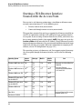
Applicable Products
HP ProCurve Wireless Access Point 420 na
HP ProCurve Wireless Access Point 420 ww
Disclaimer
(J8130A)
(J8131A)
Hewlett-Packard assumes no responsibility for the use or
reliability of its software on equipment that is not furnished
by Hewlett-Packard.
Warranty
Trademark Credits
Windows NT®, Windows®, and MS Windows® are US
registered trademarks of Microsoft Corporation.
See the Customer Support/Warranty booklet included with
the product.
A copy of the specific warranty terms applicable to your
Hewlett-Packard products and replacement parts can be
obtained from your HP Sales and Service Office or
authorized dealer.
Contents
1 Getting Started
Contents . . . . . . . . . . . . . . . . . . . . . . . . . . . . . . . . . . . . . . . . . . . . . . . . . . . . . . . 1-1
Introduction . . . . . . . . . . . . . . . . . . . . . . . . . . . . . . . . . . . . . . . . . . . . . . . . . . . 1-2
Conventions . . . . . . . . . . . . . . . . . . . . . . . . . . . . . . . . . . . . . . . . . . . . . . . . . . . 1-2
Command Syntax Statements . . . . . . . . . . . . . . . . . . . . . . . . . . . . . . . . . 1-2
Command Prompts . . . . . . . . . . . . . . . . . . . . . . . . . . . . . . . . . . . . . . . . . . 1-3
Screen Simulations . . . . . . . . . . . . . . . . . . . . . . . . . . . . . . . . . . . . . . . . . . 1-3
Related Publications . . . . . . . . . . . . . . . . . . . . . . . . . . . . . . . . . . . . . . . . . . . . 1-4
Getting Documentation From the Web . . . . . . . . . . . . . . . . . . . . . . . . . . . . . 1-5
Sources for More Information . . . . . . . . . . . . . . . . . . . . . . . . . . . . . . . . . . . . 1-6
Need Only a Quick Start? . . . . . . . . . . . . . . . . . . . . . . . . . . . . . . . . . . . . . . . . 1-6
To Set Up and Install the Access Point in Your Network . . . . . . . . . . 1-6
2 Selecting a Management Interface
Contents . . . . . . . . . . . . . . . . . . . . . . . . . . . . . . . . . . . . . . . . . . . . . . . . . . . . . . . 2-1
Overview . . . . . . . . . . . . . . . . . . . . . . . . . . . . . . . . . . . . . . . . . . . . . . . . . . . . . . 2-2
Understanding Management Interfaces . . . . . . . . . . . . . . . . . . . . . . . . . . . . . 2-2
Advantages of Using the CLI . . . . . . . . . . . . . . . . . . . . . . . . . . . . . . . . . . . . . . 2-3
Advantages of Using the HP Web Browser Interface . . . . . . . . . . . . . . . . . 2-4
3 Using the Command Line Interface (CLI)
Contents . . . . . . . . . . . . . . . . . . . . . . . . . . . . . . . . . . . . . . . . . . . . . . . . . . . . . . . 3-1
Overview . . . . . . . . . . . . . . . . . . . . . . . . . . . . . . . . . . . . . . . . . . . . . . . . . . . . . . 3-2
Accessing the CLI . . . . . . . . . . . . . . . . . . . . . . . . . . . . . . . . . . . . . . . . . . . . . . . 3-2
Direct Console Access . . . . . . . . . . . . . . . . . . . . . . . . . . . . . . . . . . . . . . . 3-2
Telnet Access . . . . . . . . . . . . . . . . . . . . . . . . . . . . . . . . . . . . . . . . . . . . . . . 3-3
Secure Shell Access . . . . . . . . . . . . . . . . . . . . . . . . . . . . . . . . . . . . . . . . . 3-3
iii
Using the CLI . . . . . . . . . . . . . . . . . . . . . . . . . . . . . . . . . . . . . . . . . . . . . . . . . . . 3-4
Command Level at Logon . . . . . . . . . . . . . . . . . . . . . . . . . . . . . . . . . . . . . 3-4
Command Level Operation . . . . . . . . . . . . . . . . . . . . . . . . . . . . . . . . . . . 3-6
Operator Privileges . . . . . . . . . . . . . . . . . . . . . . . . . . . . . . . . . . . . . . 3-6
Manager Privileges . . . . . . . . . . . . . . . . . . . . . . . . . . . . . . . . . . . . . . . 3-6
How To Move Between Levels . . . . . . . . . . . . . . . . . . . . . . . . . . . . . . . . 3-8
Listing Commands and Command Options . . . . . . . . . . . . . . . . . . . . . . 3-9
Listing Commands Available at Any Command Level . . . . . . . . . . 3-9
Command Option Displays . . . . . . . . . . . . . . . . . . . . . . . . . . . . . . . 3-11
Configuration Commands and the Context Configuration Modes . . 3-12
CLI Control and Editing . . . . . . . . . . . . . . . . . . . . . . . . . . . . . . . . . . . . . . . . . 3-16
4 Using the HP Web Browser Interface
Contents . . . . . . . . . . . . . . . . . . . . . . . . . . . . . . . . . . . . . . . . . . . . . . . . . . . . . . . 4-1
Overview . . . . . . . . . . . . . . . . . . . . . . . . . . . . . . . . . . . . . . . . . . . . . . . . . . . . . . 4-2
General Features . . . . . . . . . . . . . . . . . . . . . . . . . . . . . . . . . . . . . . . . . . . . . . . 4-3
Starting a Web Browser Interface Session with the Access Point . . . . . . . 4-4
Description of Browser Interface . . . . . . . . . . . . . . . . . . . . . . . . . . . . . . . . . . 4-5
The Home Page . . . . . . . . . . . . . . . . . . . . . . . . . . . . . . . . . . . . . . . . . . . . . 4-5
Support URL . . . . . . . . . . . . . . . . . . . . . . . . . . . . . . . . . . . . . . . . . . . . . . . 4-6
Online Help for the HP Web Browser Interface . . . . . . . . . . . . . . . . . . 4-7
Web Browser Interface Logout . . . . . . . . . . . . . . . . . . . . . . . . . . . . . . . . 4-7
Tasks for Your First HP Web Browser Interface Session . . . . . . . . . . . . . . 4-8
Changing the Manager User Name and Password in the Browser Interface . . . . . . . . . . . . . . . . . . . . . . . . . . . . . . . . . . . . . . . . . . . . . . . . . . . 4-8
If You Lose the User Name or Password . . . . . . . . . . . . . . . . . . . 4-10
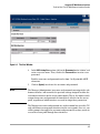
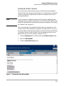
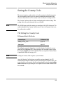
Setting SNMP Community Names . . . . . . . . . . . . . . . . . . . . . . . . . . . . . 4-10
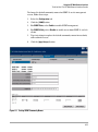
Setting the Primary SSID . . . . . . . . . . . . . . . . . . . . . . . . . . . . . . . . . . . . 4-12
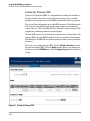
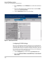
Setting the Radio Channel . . . . . . . . . . . . . . . . . . . . . . . . . . . . . . . . . . . 4-13
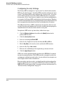
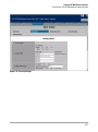
Configuring TCP/IP Settings . . . . . . . . . . . . . . . . . . . . . . . . . . . . . . . . . 4-14
Configuring Security Settings . . . . . . . . . . . . . . . . . . . . . . . . . . . . . . . . 4-16
Status Reporting Features . . . . . . . . . . . . . . . . . . . . . . . . . . . . . . . . . . . . . . . 4-18
The AP Status Window . . . . . . . . . . . . . . . . . . . . . . . . . . . . . . . . . . . . . . 4-18
Station Status . . . . . . . . . . . . . . . . . . . . . . . . . . . . . . . . . . . . . . . . . . . . . . 4-21
Event Log . . . . . . . . . . . . . . . . . . . . . . . . . . . . . . . . . . . . . . . . . . . . . . . . . 4-23
iv
The Status Bar . . . . . . . . . . . . . . . . . . . . . . . . . . . . . . . . . . . . . . . . . . . . . 4-24
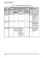
Neighbor AP Detection . . . . . . . . . . . . . . . . . . . . . . . . . . . . . . . . . . . . . .
Web: Configuring AP Detection . . . . . . . . . . . . . . . . . . . . . . . . . . .
Web: Viewing Detected Neighbor APs . . . . . . . . . . . . . . . . . . . . .
CLI: Configuring AP Detection . . . . . . . . . . . . . . . . . . . . . . . . . . . .
4-24
4-25
4-27
4-28
5 General System Configuration
Contents . . . . . . . . . . . . . . . . . . . . . . . . . . . . . . . . . . . . . . . . . . . . . . . . . . . . . . . 5-1
Overview . . . . . . . . . . . . . . . . . . . . . . . . . . . . . . . . . . . . . . . . . . . . . . . . . . . . . . 5-2
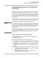
Modifying Management User Names and Passwords . . . . . . . . . . . . . . . . . 5-3
Web: Setting User Names and Passwords . . . . . . . . . . . . . . . . . . . . . . . 5-3
CLI: Setting User Names and Passwords . . . . . . . . . . . . . . . . . . . . . . . . 5-5
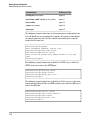
Setting Management Access Controls . . . . . . . . . . . . . . . . . . . . . . . . . . . . . . 5-7
Web: Configuring Management Controls . . . . . . . . . . . . . . . . . . . . . . . . 5-8
CLI: Configuring Management Controls . . . . . . . . . . . . . . . . . . . . . . . . . 5-9
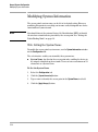
Modifying System Information . . . . . . . . . . . . . . . . . . . . . . . . . . . . . . . . . . . 5-12
Web: Setting the System Name . . . . . . . . . . . . . . . . . . . . . . . . . . . . . . . 5-12
CLI: Setting the System Name . . . . . . . . . . . . . . . . . . . . . . . . . . . . . . . . 5-13
Configuring IP Settings . . . . . . . . . . . . . . . . . . . . . . . . . . . . . . . . . . . . . . . . . 5-15
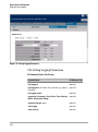
Web: Configuring IP Settings Statically or via DHCP . . . . . . . . . . . . . 5-15
CLI: Configuring IP Settings Statically or via DHCP . . . . . . . . . . . . . . 5-17
Configuring SNMP . . . . . . . . . . . . . . . . . . . . . . . . . . . . . . . . . . . . . . . . . . . . . 5-19
Web: Setting Basic SNMP Parameters . . . . . . . . . . . . . . . . . . . . . . . . . 5-19
CLI: Setting Basic SNMP Parameters . . . . . . . . . . . . . . . . . . . . . . . . . . 5-21
Web: Configuring SNMP v3 Users . . . . . . . . . . . . . . . . . . . . . . . . . . . . . 5-24
CLI: Configuring SNMP v3 Users . . . . . . . . . . . . . . . . . . . . . . . . . . . . . 5-26
Web: Configuring SNMP v3 Trap Targets and filters . . . . . . . . . . . . . 5-27
CLI: Configuring SNMP v3 Trap Targets and Filters . . . . . . . . . . . . . 5-32
Web: Configuring SNMP v1 and v2c Trap Destinations . . . . . . . . . . . 5-33
CLI: Configuring SNMP v1 and v2c Trap Destinations . . . . . . . . . . . . 5-37
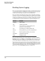
Enabling System Logging . . . . . . . . . . . . . . . . . . . . . . . . . . . . . . . . . . . . . . . 5-40
Web: Setting Logging Parameters . . . . . . . . . . . . . . . . . . . . . . . . . . . . . 5-41
CLI: Setting Logging Parameters . . . . . . . . . . . . . . . . . . . . . . . . . . . . . . 5-42
v
Configuring SNTP . . . . . . . . . . . . . . . . . . . . . . . . . . . . . . . . . . . . . . . . . . . . . . 5-45
Web: Setting SNTP Parameters . . . . . . . . . . . . . . . . . . . . . . . . . . . . . . . 5-45
CLI: Setting SNTP Parameters . . . . . . . . . . . . . . . . . . . . . . . . . . . . . . . . 5-47
Configuring Ethernet Interface Parameters . . . . . . . . . . . . . . . . . . . . . . . . 5-49
Web: Setting Ethernet Interface Parameters . . . . . . . . . . . . . . . . . . . . 5-49
CLI: Setting Ethernet Interface Parameters . . . . . . . . . . . . . . . . . . . . . 5-50
Configuring RADIUS Accounting . . . . . . . . . . . . . . . . . . . . . . . . . . . . . . . . . 5-52
Web: Setting RADIUS Accounting Server Parameters . . . . . . . . . . . . 5-53
CLI: Setting RADIUS Accounting Server Parameters . . . . . . . . . . . . . 5-55
Setting up Filter Control . . . . . . . . . . . . . . . . . . . . . . . . . . . . . . . . . . . . . . . . 5-58
Web: Setting Traffic Filters . . . . . . . . . . . . . . . . . . . . . . . . . . . . . . . . . . 5-58
CLI: Setting Traffic Filters . . . . . . . . . . . . . . . . . . . . . . . . . . . . . . . . . . . 5-60
Configuring VLAN Support . . . . . . . . . . . . . . . . . . . . . . . . . . . . . . . . . . . . . . 5-62
Web: Enabling VLAN Support . . . . . . . . . . . . . . . . . . . . . . . . . . . . . . . . 5-63
CLI: Enabling VLAN Support . . . . . . . . . . . . . . . . . . . . . . . . . . . . . . . . . 5-65
6 Wireless Interface Configuration
Contents . . . . . . . . . . . . . . . . . . . . . . . . . . . . . . . . . . . . . . . . . . . . . . . . . . . . . . . 6-1
Overview . . . . . . . . . . . . . . . . . . . . . . . . . . . . . . . . . . . . . . . . . . . . . . . . . . . . . . 6-2
Setting the Country Code . . . . . . . . . . . . . . . . . . . . . . . . . . . . . . . . . . . . . . . . 6-3
CLI: Setting the Country Code . . . . . . . . . . . . . . . . . . . . . . . . . . . . . . . . . 6-3
Setting the Radio Working Mode . . . . . . . . . . . . . . . . . . . . . . . . . . . . . . . . . . 6-6
Web: Setting the Radio Working Mode . . . . . . . . . . . . . . . . . . . . . . . . . . 6-7
CLI: Setting the Radio Working Mode . . . . . . . . . . . . . . . . . . . . . . . . . . 6-8
Configuring Radio Settings . . . . . . . . . . . . . . . . . . . . . . . . . . . . . . . . . . . . . . 6-10
Web: Configuring Radio Settings . . . . . . . . . . . . . . . . . . . . . . . . . . . . . . 6-10
CLI: Configuring Radio Settings . . . . . . . . . . . . . . . . . . . . . . . . . . . . . . 6-13
Modifying Antenna Settings . . . . . . . . . . . . . . . . . . . . . . . . . . . . . . . . . . . . . 6-16
Web: Setting the Antenna Mode and Transmit Power Control Limits . . . . . . . . . . . . . . . . . . . . . . . . . . . . . . . . . . . . . . . . . . . . . . . . . . . . 6-18
CLI: Setting the Antenna Mode and Transmit Power Control Limits 6-19
Managing Multiple SSID Interfaces . . . . . . . . . . . . . . . . . . . . . . . . . . . . . . . 6-22
Web: Creating an SSID Interface . . . . . . . . . . . . . . . . . . . . . . . . . . . . . . 6-22
vi
CLI: Creating an SSID Interface . . . . . . . . . . . . . . . . . . . . . . . . . . . . . . 6-24
Web: Modifying SSID Interface Settings . . . . . . . . . . . . . . . . . . . . . . . 6-25
CLI: Modifying SSID Interface Settings . . . . . . . . . . . . . . . . . . . . . . . . 6-27
7 Wireless Security Configuration
Contents . . . . . . . . . . . . . . . . . . . . . . . . . . . . . . . . . . . . . . . . . . . . . . . . . . . . . . . 7-1
Overview . . . . . . . . . . . . . . . . . . . . . . . . . . . . . . . . . . . . . . . . . . . . . . . . . . . . . . 7-2
Wireless Security Overview . . . . . . . . . . . . . . . . . . . . . . . . . . . . . . . . . . . . . . 7-3
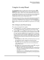
Using the Security Wizard . . . . . . . . . . . . . . . . . . . . . . . . . . . . . . . . . . . . . . . 7-11
Web: Setting Security Wizard Options . . . . . . . . . . . . . . . . . . . . . . . . . 7-11
CLI: Configuring Security Settings . . . . . . . . . . . . . . . . . . . . . . . . . . . . 7-19
Configuring RADIUS Client Authentication . . . . . . . . . . . . . . . . . . . . . . . . 7-25
Web: Setting RADIUS Server Parameters . . . . . . . . . . . . . . . . . . . . . . 7-26
CLI: Setting RADIUS Server Parameters . . . . . . . . . . . . . . . . . . . . . . . 7-28
Configuring MAC Address Authentication . . . . . . . . . . . . . . . . . . . . . . . . . 7-31
Web: Configuring MAC Address Authentication . . . . . . . . . . . . . . . . . 7-32
CLI: Configuring MAC Address Authentication . . . . . . . . . . . . . . . . . 7-34
8 Command Line Reference
Contents . . . . . . . . . . . . . . . . . . . . . . . . . . . . . . . . . . . . . . . . . . . . . . . . . . . . . . . 8-1
Overview . . . . . . . . . . . . . . . . . . . . . . . . . . . . . . . . . . . . . . . . . . . . . . . . . . . . . . 8-2
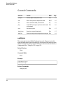
General Commands . . . . . . . . . . . . . . . . . . . . . . . . . . . . . . . . . . . . . . . . . . . . . 8-4
configure . . . . . . . . . . . . . . . . . . . . . . . . . . . . . . . . . . . . . . . . . . . . . . . . . . . 8-4
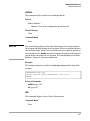
end . . . . . . . . . . . . . . . . . . . . . . . . . . . . . . . . . . . . . . . . . . . . . . . . . . . . . . . . 8-5
exit . . . . . . . . . . . . . . . . . . . . . . . . . . . . . . . . . . . . . . . . . . . . . . . . . . . . . . . . 8-5
ping . . . . . . . . . . . . . . . . . . . . . . . . . . . . . . . . . . . . . . . . . . . . . . . . . . . . . . . 8-6
reset . . . . . . . . . . . . . . . . . . . . . . . . . . . . . . . . . . . . . . . . . . . . . . . . . . . . . . . 8-7
show history . . . . . . . . . . . . . . . . . . . . . . . . . . . . . . . . . . . . . . . . . . . . . . . . 8-7
show line . . . . . . . . . . . . . . . . . . . . . . . . . . . . . . . . . . . . . . . . . . . . . . . . . . 8-8
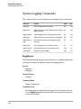
System Management Commands . . . . . . . . . . . . . . . . . . . . . . . . . . . . . . . . . . 8-9
country . . . . . . . . . . . . . . . . . . . . . . . . . . . . . . . . . . . . . . . . . . . . . . . . . . . 8-10
prompt . . . . . . . . . . . . . . . . . . . . . . . . . . . . . . . . . . . . . . . . . . . . . . . . . . . 8-12
system name . . . . . . . . . . . . . . . . . . . . . . . . . . . . . . . . . . . . . . . . . . . . . . 8-13
vii
management . . . . . . . . . . . . . . . . . . . . . . . . . . . . . . . . . . . . . . . . . . . . . . . 8-13
username-admin . . . . . . . . . . . . . . . . . . . . . . . . . . . . . . . . . . . . . . . . . . . 8-14
password-admin . . . . . . . . . . . . . . . . . . . . . . . . . . . . . . . . . . . . . . . . . . . 8-14
user add . . . . . . . . . . . . . . . . . . . . . . . . . . . . . . . . . . . . . . . . . . . . . . . . . . 8-15
user del . . . . . . . . . . . . . . . . . . . . . . . . . . . . . . . . . . . . . . . . . . . . . . . . . . . 8-16
user pwd . . . . . . . . . . . . . . . . . . . . . . . . . . . . . . . . . . . . . . . . . . . . . . . . . . 8-16
cli serial . . . . . . . . . . . . . . . . . . . . . . . . . . . . . . . . . . . . . . . . . . . . . . . . . . 8-17
cli telnet . . . . . . . . . . . . . . . . . . . . . . . . . . . . . . . . . . . . . . . . . . . . . . . . . . 8-17
ssh enable . . . . . . . . . . . . . . . . . . . . . . . . . . . . . . . . . . . . . . . . . . . . . . . . . 8-18
ssh port . . . . . . . . . . . . . . . . . . . . . . . . . . . . . . . . . . . . . . . . . . . . . . . . . . . 8-19
snmpv3 . . . . . . . . . . . . . . . . . . . . . . . . . . . . . . . . . . . . . . . . . . . . . . . . . . . 8-19
reset-button enable . . . . . . . . . . . . . . . . . . . . . . . . . . . . . . . . . . . . . . . . . 8-20
show users . . . . . . . . . . . . . . . . . . . . . . . . . . . . . . . . . . . . . . . . . . . . . . . . 8-21
http port . . . . . . . . . . . . . . . . . . . . . . . . . . . . . . . . . . . . . . . . . . . . . . . . . . 8-21
http server . . . . . . . . . . . . . . . . . . . . . . . . . . . . . . . . . . . . . . . . . . . . . . . . 8-22
https port . . . . . . . . . . . . . . . . . . . . . . . . . . . . . . . . . . . . . . . . . . . . . . . . . 8-23
https server . . . . . . . . . . . . . . . . . . . . . . . . . . . . . . . . . . . . . . . . . . . . . . . 8-23
svp . . . . . . . . . . . . . . . . . . . . . . . . . . . . . . . . . . . . . . . . . . . . . . . . . . . . . . . 8-24
show svp . . . . . . . . . . . . . . . . . . . . . . . . . . . . . . . . . . . . . . . . . . . . . . . . . . 8-25
show system . . . . . . . . . . . . . . . . . . . . . . . . . . . . . . . . . . . . . . . . . . . . . . . 8-25
show version . . . . . . . . . . . . . . . . . . . . . . . . . . . . . . . . . . . . . . . . . . . . . . 8-26
show hardware . . . . . . . . . . . . . . . . . . . . . . . . . . . . . . . . . . . . . . . . . . . . 8-27
System Logging Commands . . . . . . . . . . . . . . . . . . . . . . . . . . . . . . . . . . . . . 8-28
logging on . . . . . . . . . . . . . . . . . . . . . . . . . . . . . . . . . . . . . . . . . . . . . . . . . 8-28
logging host . . . . . . . . . . . . . . . . . . . . . . . . . . . . . . . . . . . . . . . . . . . . . . . 8-29
logging console . . . . . . . . . . . . . . . . . . . . . . . . . . . . . . . . . . . . . . . . . . . . 8-29
logging level . . . . . . . . . . . . . . . . . . . . . . . . . . . . . . . . . . . . . . . . . . . . . . . 8-30
logging facility-type . . . . . . . . . . . . . . . . . . . . . . . . . . . . . . . . . . . . . . . . . 8-31
logging clear . . . . . . . . . . . . . . . . . . . . . . . . . . . . . . . . . . . . . . . . . . . . . . . 8-31
show event-log . . . . . . . . . . . . . . . . . . . . . . . . . . . . . . . . . . . . . . . . . . . . . 8-32
show logging . . . . . . . . . . . . . . . . . . . . . . . . . . . . . . . . . . . . . . . . . . . . . . 8-32
System Clock Commands . . . . . . . . . . . . . . . . . . . . . . . . . . . . . . . . . . . . . . . 8-34
sntp-server ip . . . . . . . . . . . . . . . . . . . . . . . . . . . . . . . . . . . . . . . . . . . . . . 8-34
sntp-server enable . . . . . . . . . . . . . . . . . . . . . . . . . . . . . . . . . . . . . . . . . . 8-35
sntp-server date-time . . . . . . . . . . . . . . . . . . . . . . . . . . . . . . . . . . . . . . . 8-36
viii
sntp-server daylight-saving . . . . . . . . . . . . . . . . . . . . . . . . . . . . . . . . . . 8-36
sntp-server timezone . . . . . . . . . . . . . . . . . . . . . . . . . . . . . . . . . . . . . . . . 8-37
show sntp . . . . . . . . . . . . . . . . . . . . . . . . . . . . . . . . . . . . . . . . . . . . . . . . . 8-38
SNMP Commands . . . . . . . . . . . . . . . . . . . . . . . . . . . . . . . . . . . . . . . . . . . . . . 8-39
snmp-server community . . . . . . . . . . . . . . . . . . . . . . . . . . . . . . . . . . . . . 8-40
snmp-server contact . . . . . . . . . . . . . . . . . . . . . . . . . . . . . . . . . . . . . . . . 8-41
snmp-server enable server . . . . . . . . . . . . . . . . . . . . . . . . . . . . . . . . . . . 8-41
snmp-server host . . . . . . . . . . . . . . . . . . . . . . . . . . . . . . . . . . . . . . . . . . 8-42
snmp-server trap . . . . . . . . . . . . . . . . . . . . . . . . . . . . . . . . . . . . . . . . . . . 8-43
snmp-server location . . . . . . . . . . . . . . . . . . . . . . . . . . . . . . . . . . . . . . . 8-46
snmpv3 engine-id . . . . . . . . . . . . . . . . . . . . . . . . . . . . . . . . . . . . . . . . . . . 8-46
snmpv3 user . . . . . . . . . . . . . . . . . . . . . . . . . . . . . . . . . . . . . . . . . . . . . . . 8-47
snmpv3 targets . . . . . . . . . . . . . . . . . . . . . . . . . . . . . . . . . . . . . . . . . . . . . 8-49
snmpv3 filter . . . . . . . . . . . . . . . . . . . . . . . . . . . . . . . . . . . . . . . . . . . . . . 8-50
snmpv3 filter-assignments . . . . . . . . . . . . . . . . . . . . . . . . . . . . . . . . . . . 8-51
show snmpv3 . . . . . . . . . . . . . . . . . . . . . . . . . . . . . . . . . . . . . . . . . . . . . . 8-52
show snmp-server . . . . . . . . . . . . . . . . . . . . . . . . . . . . . . . . . . . . . . . . . . 8-53
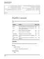
Flash/File Commands . . . . . . . . . . . . . . . . . . . . . . . . . . . . . . . . . . . . . . . . . . 8-54
bootfile . . . . . . . . . . . . . . . . . . . . . . . . . . . . . . . . . . . . . . . . . . . . . . . . . . . 8-54
copy
. . . . . . . . . . . . . . . . . . . . . . . . . . . . . . . . . . . . . . . . . . . . . . . . . . . . 8-55
delete . . . . . . . . . . . . . . . . . . . . . . . . . . . . . . . . . . . . . . . . . . . . . . . . . . . . . 8-57
dir . . . . . . . . . . . . . . . . . . . . . . . . . . . . . . . . . . . . . . . . . . . . . . . . . . . . . . . 8-57
show bootfile . . . . . . . . . . . . . . . . . . . . . . . . . . . . . . . . . . . . . . . . . . . . . . 8-58
show text-config-file . . . . . . . . . . . . . . . . . . . . . . . . . . . . . . . . . . . . . . . . 8-59
show text-config-error . . . . . . . . . . . . . . . . . . . . . . . . . . . . . . . . . . . . . . 8-60
RADIUS Authentication . . . . . . . . . . . . . . . . . . . . . . . . . . . . . . . . . . . . . . . . . 8-61
radius-authentication-server address . . . . . . . . . . . . . . . . . . . . . . . . . . 8-61
radius-authentication-server port . . . . . . . . . . . . . . . . . . . . . . . . . . . . . 8-62
radius-authentication-server key . . . . . . . . . . . . . . . . . . . . . . . . . . . . . . 8-62
radius-authentication-server retransmit . . . . . . . . . . . . . . . . . . . . . . . . 8-63
radius-authentication-server timeout . . . . . . . . . . . . . . . . . . . . . . . . . . 8-64
radius-authentication-server mac-format . . . . . . . . . . . . . . . . . . . . . . . 8-64
radius-authentication-server vlan-format . . . . . . . . . . . . . . . . . . . . . . . 8-65
show radius . . . . . . . . . . . . . . . . . . . . . . . . . . . . . . . . . . . . . . . . . . . . . . . 8-65
ix
RADIUS Accounting . . . . . . . . . . . . . . . . . . . . . . . . . . . . . . . . . . . . . . . . . . . . 8-67
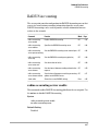
radius-accounting-server enable . . . . . . . . . . . . . . . . . . . . . . . . . . . . . . 8-67
radius-accounting-server address . . . . . . . . . . . . . . . . . . . . . . . . . . . . . 8-68
radius-accounting-server port-accounting . . . . . . . . . . . . . . . . . . . . . . 8-68
radius-accounting-server key . . . . . . . . . . . . . . . . . . . . . . . . . . . . . . . . . 8-69
radius-accounting-server retransmit . . . . . . . . . . . . . . . . . . . . . . . . . . . 8-69
radius-accounting-server timeout . . . . . . . . . . . . . . . . . . . . . . . . . . . . . 8-70
radius-accounting-server timeout-interim . . . . . . . . . . . . . . . . . . . . . . 8-71
802.1X Authentication . . . . . . . . . . . . . . . . . . . . . . . . . . . . . . . . . . . . . . . . . . 8-72
802.1x broadcast-key-refresh-rate . . . . . . . . . . . . . . . . . . . . . . . . . . . . . 8-72
802.1x session-key-refresh-rate . . . . . . . . . . . . . . . . . . . . . . . . . . . . . . . 8-73
802.1x session-timeout . . . . . . . . . . . . . . . . . . . . . . . . . . . . . . . . . . . . . . 8-74
802.1x supplicant user . . . . . . . . . . . . . . . . . . . . . . . . . . . . . . . . . . . . . . 8-74
802.1x supplicant . . . . . . . . . . . . . . . . . . . . . . . . . . . . . . . . . . . . . . . . . . . 8-75
show authentication . . . . . . . . . . . . . . . . . . . . . . . . . . . . . . . . . . . . . . . . 8-76
MAC Address Authentication . . . . . . . . . . . . . . . . . . . . . . . . . . . . . . . . . . . . 8-78
mac-access permission . . . . . . . . . . . . . . . . . . . . . . . . . . . . . . . . . . . . . . 8-78
mac-access entry . . . . . . . . . . . . . . . . . . . . . . . . . . . . . . . . . . . . . . . . . . . 8-79
mac-authentication server . . . . . . . . . . . . . . . . . . . . . . . . . . . . . . . . . . . 8-80
mac-authentication session-timeout . . . . . . . . . . . . . . . . . . . . . . . . . . . 8-81
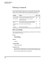
Filtering Commands . . . . . . . . . . . . . . . . . . . . . . . . . . . . . . . . . . . . . . . . . . . . 8-82
filter local-bridge . . . . . . . . . . . . . . . . . . . . . . . . . . . . . . . . . . . . . . . . . . . 8-82
filter ap-manage . . . . . . . . . . . . . . . . . . . . . . . . . . . . . . . . . . . . . . . . . . . . 8-83
filter ethernet-type enable . . . . . . . . . . . . . . . . . . . . . . . . . . . . . . . . . . . 8-83
filter ethernet-type protocol . . . . . . . . . . . . . . . . . . . . . . . . . . . . . . . . . . 8-84
show filters . . . . . . . . . . . . . . . . . . . . . . . . . . . . . . . . . . . . . . . . . . . . . . . . 8-85
Ethernet Interface Commands . . . . . . . . . . . . . . . . . . . . . . . . . . . . . . . . . . . 8-86
interface ethernet . . . . . . . . . . . . . . . . . . . . . . . . . . . . . . . . . . . . . . . . . . 8-86
dns server . . . . . . . . . . . . . . . . . . . . . . . . . . . . . . . . . . . . . . . . . . . . . . . . . 8-87
ip address . . . . . . . . . . . . . . . . . . . . . . . . . . . . . . . . . . . . . . . . . . . . . . . . 8-88
ip dhcp . . . . . . . . . . . . . . . . . . . . . . . . . . . . . . . . . . . . . . . . . . . . . . . . . . . 8-89
shutdown . . . . . . . . . . . . . . . . . . . . . . . . . . . . . . . . . . . . . . . . . . . . . . . . . 8-90
speed-duplex . . . . . . . . . . . . . . . . . . . . . . . . . . . . . . . . . . . . . . . . . . . . . . 8-90
show interface ethernet . . . . . . . . . . . . . . . . . . . . . . . . . . . . . . . . . . . . . 8-91
Wireless Interface Commands . . . . . . . . . . . . . . . . . . . . . . . . . . . . . . . . . . . 8-93
interface wireless g . . . . . . . . . . . . . . . . . . . . . . . . . . . . . . . . . . . . . . . . . 8-94
ssid add . . . . . . . . . . . . . . . . . . . . . . . . . . . . . . . . . . . . . . . . . . . . . . . . . . . 8-95
ssid . . . . . . . . . . . . . . . . . . . . . . . . . . . . . . . . . . . . . . . . . . . . . . . . . . . . . . 8-96
ssid-name . . . . . . . . . . . . . . . . . . . . . . . . . . . . . . . . . . . . . . . . . . . . . . . . . 8-96
primary . . . . . . . . . . . . . . . . . . . . . . . . . . . . . . . . . . . . . . . . . . . . . . . . . . . 8-97
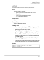
description . . . . . . . . . . . . . . . . . . . . . . . . . . . . . . . . . . . . . . . . . . . . . . . . 8-97
closed-system . . . . . . . . . . . . . . . . . . . . . . . . . . . . . . . . . . . . . . . . . . . . . . 8-98
radio-mode . . . . . . . . . . . . . . . . . . . . . . . . . . . . . . . . . . . . . . . . . . . . . . . . 8-99
antenna-mode . . . . . . . . . . . . . . . . . . . . . . . . . . . . . . . . . . . . . . . . . . . . . 8-99
speed . . . . . . . . . . . . . . . . . . . . . . . . . . . . . . . . . . . . . . . . . . . . . . . . . . . . 8-100
multicast-data-rate . . . . . . . . . . . . . . . . . . . . . . . . . . . . . . . . . . . . . . . . 8-101
channel . . . . . . . . . . . . . . . . . . . . . . . . . . . . . . . . . . . . . . . . . . . . . . . . . . 8-101
beacon-interval . . . . . . . . . . . . . . . . . . . . . . . . . . . . . . . . . . . . . . . . . . . 8-102
dtim-period . . . . . . . . . . . . . . . . . . . . . . . . . . . . . . . . . . . . . . . . . . . . . . . 8-103
fragmentation-length . . . . . . . . . . . . . . . . . . . . . . . . . . . . . . . . . . . . . . . 8-104
rts-threshold . . . . . . . . . . . . . . . . . . . . . . . . . . . . . . . . . . . . . . . . . . . . . . 8-105
slot-time . . . . . . . . . . . . . . . . . . . . . . . . . . . . . . . . . . . . . . . . . . . . . . . . . 8-106
preamble . . . . . . . . . . . . . . . . . . . . . . . . . . . . . . . . . . . . . . . . . . . . . . . . . 8-107
transmit-limits . . . . . . . . . . . . . . . . . . . . . . . . . . . . . . . . . . . . . . . . . . . . 8-107
transmit-power . . . . . . . . . . . . . . . . . . . . . . . . . . . . . . . . . . . . . . . . . . . 8-108
max-association . . . . . . . . . . . . . . . . . . . . . . . . . . . . . . . . . . . . . . . . . . . 8-109
shutdown . . . . . . . . . . . . . . . . . . . . . . . . . . . . . . . . . . . . . . . . . . . . . . . . 8-110
enable . . . . . . . . . . . . . . . . . . . . . . . . . . . . . . . . . . . . . . . . . . . . . . . . . . . 8-110
show interface wireless g . . . . . . . . . . . . . . . . . . . . . . . . . . . . . . . . . . . 8-111
show ssid . . . . . . . . . . . . . . . . . . . . . . . . . . . . . . . . . . . . . . . . . . . . . . . . 8-112
show ssid-list . . . . . . . . . . . . . . . . . . . . . . . . . . . . . . . . . . . . . . . . . . . . . 8-113
show station . . . . . . . . . . . . . . . . . . . . . . . . . . . . . . . . . . . . . . . . . . . . . . 8-114
Wireless Security Commands . . . . . . . . . . . . . . . . . . . . . . . . . . . . . . . . . . . 8-115
transmit-key-wep . . . . . . . . . . . . . . . . . . . . . . . . . . . . . . . . . . . . . . . . . . 8-115
security-suite . . . . . . . . . . . . . . . . . . . . . . . . . . . . . . . . . . . . . . . . . . . . . 8-117
wpa-preshared-key . . . . . . . . . . . . . . . . . . . . . . . . . . . . . . . . . . . . . . . . 8-120
pre-authentication enable . . . . . . . . . . . . . . . . . . . . . . . . . . . . . . . . . . 8-121
pmksa-lifetime . . . . . . . . . . . . . . . . . . . . . . . . . . . . . . . . . . . . . . . . . . . . 8-122
show wep-key . . . . . . . . . . . . . . . . . . . . . . . . . . . . . . . . . . . . . . . . . . . . 8-123
xi
Neighbor AP Detection Commands . . . . . . . . . . . . . . . . . . . . . . . . . . . . . . 8-124
ap-detection . . . . . . . . . . . . . . . . . . . . . . . . . . . . . . . . . . . . . . . . . . . . . . 8-124
ap-detection duration . . . . . . . . . . . . . . . . . . . . . . . . . . . . . . . . . . . . . . 8-125
ap-detection interval . . . . . . . . . . . . . . . . . . . . . . . . . . . . . . . . . . . . . . . 8-126
ap-detection first-scan . . . . . . . . . . . . . . . . . . . . . . . . . . . . . . . . . . . . . 8-126
ap-detection instant-scan . . . . . . . . . . . . . . . . . . . . . . . . . . . . . . . . . . . 8-127
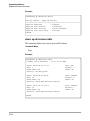
show ap-detection config . . . . . . . . . . . . . . . . . . . . . . . . . . . . . . . . . . . 8-127
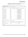
show ap-detection table . . . . . . . . . . . . . . . . . . . . . . . . . . . . . . . . . . . . 8-128
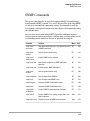
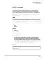
IAPP Command . . . . . . . . . . . . . . . . . . . . . . . . . . . . . . . . . . . . . . . . . . . . . . . 8-129
iapp . . . . . . . . . . . . . . . . . . . . . . . . . . . . . . . . . . . . . . . . . . . . . . . . . . . . . 8-129
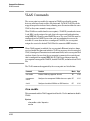
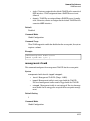
VLAN Commands . . . . . . . . . . . . . . . . . . . . . . . . . . . . . . . . . . . . . . . . . . . . . 8-130
vlan enable . . . . . . . . . . . . . . . . . . . . . . . . . . . . . . . . . . . . . . . . . . . . . . . 8-130
management-vlanid . . . . . . . . . . . . . . . . . . . . . . . . . . . . . . . . . . . . . . . . 8-131
vlan-id . . . . . . . . . . . . . . . . . . . . . . . . . . . . . . . . . . . . . . . . . . . . . . . . . . . 8-132
A File Transfers
Contents . . . . . . . . . . . . . . . . . . . . . . . . . . . . . . . . . . . . . . . . . . . . . . . . . . . . . . A-1
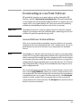
Overview . . . . . . . . . . . . . . . . . . . . . . . . . . . . . . . . . . . . . . . . . . . . . . . . . . . . . A-2
Downloading Access Point Software . . . . . . . . . . . . . . . . . . . . . . . . . . . . . . A-3
General Software Download Rules . . . . . . . . . . . . . . . . . . . . . . . . . . . . A-3
Using TFTP or FTP To Download Software from a Server . . . . . . . . A-4
Web: TFTP/FTP Software Download to the Access Point . . . . . A-4
CLI: TFTP/FTP Software Download to the Access Point . . . . . . A-6
Using the Web Interface To Download Software From the Local
Computer . . . . . . . . . . . . . . . . . . . . . . . . . . . . . . . . . . . . . . . . . . . . . . . . . A-8
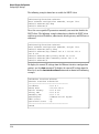
Upgrade Procedure for v2.1.x Software . . . . . . . . . . . . . . . . . . . . . . . . . . A-10
CLI: Version 2.1.x Software Upgrade using TFTP/FTP . . . . . . . A-11
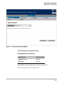
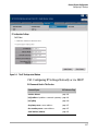
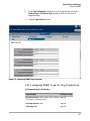
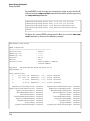
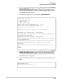
Transferring Configuration Files . . . . . . . . . . . . . . . . . . . . . . . . . . . . . . . . A-14
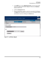
Web: Configuration File Upload and Download . . . . . . . . . . . . . . . . A-14
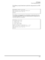
CLI: Configuration File Upload and Download . . . . . . . . . . . . . . . . . A-16
xii
1
Getting Started
Contents
Introduction . . . . . . . . . . . . . . . . . . . . . . . . . . . . . . . . . . . . . . . . . . . . . . . . . . . 1-2
Conventions . . . . . . . . . . . . . . . . . . . . . . . . . . . . . . . . . . . . . . . . . . . . . . . . . . . 1-2
Command Syntax Statements . . . . . . . . . . . . . . . . . . . . . . . . . . . . . . . . . 1-2
Command Prompts . . . . . . . . . . . . . . . . . . . . . . . . . . . . . . . . . . . . . . . . . . 1-3
Screen Simulations . . . . . . . . . . . . . . . . . . . . . . . . . . . . . . . . . . . . . . . . . . 1-3
Related Publications . . . . . . . . . . . . . . . . . . . . . . . . . . . . . . . . . . . . . . . . . . . . 1-4
Getting Documentation From the Web . . . . . . . . . . . . . . . . . . . . . . . . . . . . . 1-5
Sources for More Information . . . . . . . . . . . . . . . . . . . . . . . . . . . . . . . . . . . . 1-6
Need Only a Quick Start? . . . . . . . . . . . . . . . . . . . . . . . . . . . . . . . . . . . . . . . . 1-6
To Set Up and Install the Access Point in Your Network . . . . . . . . . . 1-6
1-1
Getting Started
Introduction
Introduction
This Management and Configuration Guide is intended to support the
following access points:
■
HP ProCurve Wireless Access Point 420 na
■
HP ProCurve Wireless Access Point 420 ww
This guide describes how to use the command line interface (CLI) and web
browser interface to configure, manage, and monitor access point operation.
A troubleshooting chapter is also included.
For information on other product documentation for this access point, refer
to “Related Publications” on page 1-4.
The Product Documentation CD-ROM shipped with the access point includes
a copy of this guide. You can also download a copy from the HP ProCurve
website, http://www.hp.com/go/hpprocurve. (See “Getting Documentation From
the Web” on page 1-5.)
Conventions
This guide uses the following conventions for command syntax and displayed
information.
Command Syntax Statements
Syntax: radius-server address [secondary] <host_ip_address | host_name>
■
Vertical bars ( | ) separate alternative, mutually exclusive elements.
■
Square brackets ( [ ] ) indicate optional elements.
■
Braces ( < > ) enclose required elements.
■
Braces within square brackets ( [ < > ] ) indicate a required element
within an optional choice.
■
Boldface indicates use of a CLI command, part of a CLI command
syntax, or other displayed element in general text. For example:
“Use the copy tftp command to download the key from a TFTP server.”
1-2
Getting Started
Conventions
■
Italics indicate variables for which you must supply a value when
executing the command. For example, in this command syntax,
<host_ip_address | host_name > indicates that you must provide an IP
address or a host name:
Syntax: radius-accounting-server [secondary] address <host_ip_address |
host_name>
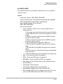
Command Prompts
In the default configuration, your access point displays the following CLI
prompt:
HP ProCurve Access Point 420#
To simplify recognition, this guide uses HP420 to represent command
prompt. For example:
HP420#
(You can use the prompt command to change the text in the CLI prompt.)
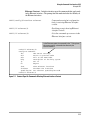
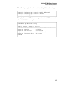
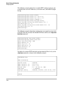
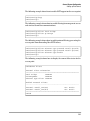
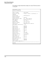
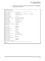
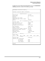
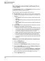
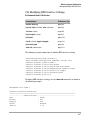
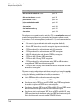
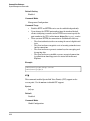
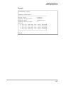
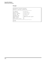
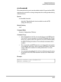
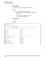
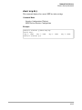
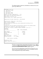
Screen Simulations
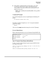
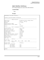
Figures containing simulated screen text and command output look like this:
HP420#show version
Software Version
: v2.1.0.0B12
Boot Rom Version
: v3.0.6
Hardware version
: R02
HP420#
Figure 1-1. Example of a Figure Showing a Simulated Screen
In some cases, brief command-output sequences appear outside of a num
bered figure. For example:
HP420(if-ethernet)#ip address 192.168.1.2 255.255.255.0 192.168.1.253
HP420(if-ethernet)#dns primary-server 192.168.1.55
1-3
Getting Started
Related Publications
Related Publications
Installation and Getting Started Guide. Use the Installation and Getting Started Guide shipped with your access point to prepare for and perform
the physical installation. This guide also steps you through connecting the
access point to your network and assigning IP addressing, as well as describ
ing the LED indications for correct operation and trouble analysis.
HP provides a PDF version of this guide on the Product Documentation
CD-ROM shipped with the access point. You can also download a copy from
the HP ProCurve website. (See “Getting Documentation From the Web” on
page 1-5.)
Release Notes. Release notes are posted on the HP ProCurve website and
provide information on new software updates:
■
New features and how to configure and use them
■
Software management, including downloading software to the access
point
■
Software fixes addressed in current and previous releases
To view and download a copy of the latest release notes for your access point,
see “Getting Documentation From the Web” on page 1-5.
1-4
Getting Started
Getting Documentation From the Web
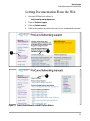
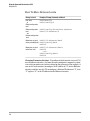
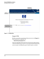
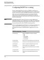
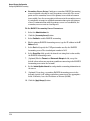
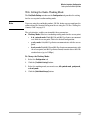
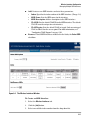
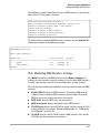
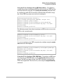
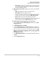
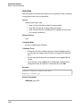
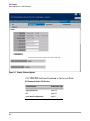
Getting Documentation From the Web
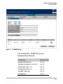
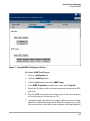
1.
Go to the HP ProCurve website at
http://www.hp.com/go/hpprocurve
2.
Click on Technical support.
3.
Click on Product manuals.
4.
Click on the product for which you want to view or download a manual.
3
2
4
Figure 1-2. Finding Product Manuals on the HP ProCurve Website
1-5
Getting Started
Sources for More Information
Sources for More Information
■
If you need information on specific features in the HP Web Browser
Interface (hereafter referred to as the “web browser interface”), use
the online help available for the web browser interface. For more
information on web browser Help options, refer to “Online Help for
the HP Web Browser Interface” on page 4-7.
■
If you need further information on Hewlett-Packard access point
technology, visit the HP ProCurve website at:
http://www.hp.com/go/hpprocurve
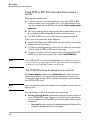
Need Only a Quick Start?
IP Addressing. If you just want to give the access point an IP address so that
it can communicate on your network, HP recommends that you use the CLI
to quickly configure IP addressing. To do so, do one of the following:
■
Enter config at the CLI Exec level prompt.
HP420#config
■
Enter interface ethernet at the CLI Configuration level prompt.
HP420(config)#interface ethernet
■
Enter the IP address, subnet mask, and gateway at the CLI Interface
Configuration level prompt.
HP420(if-ethernet)#ip address <address>
<subnet_mask> <gateway>
For more on using the CLI, see Chapter 8, “Using the Command Line Interface
(CLI)”.
To Set Up and Install the Access Point in Your Network
Important!
1-6
Use the Installation and Getting Started Guide shipped with your access
point for the following:
■
Notes, cautions, and warnings related to installing and using the
access point
■
Instructions for physically installing the access point in your network
Getting Started
Need Only a Quick Start?
■
Quickly assigning an IP address, subnet mask, and gateway, set a
Manager password, and (optionally) configure other basic features.
■
Interpreting LED behavior.
For the latest version of the Installation and Getting Started Guide and other
documentation for your access point, visit to the HP ProCurve website. (Refer
to “Getting Documentation From the Web” on page 1-5.)
1-7
— This page is intentionally unused. —
2
Selecting a Management Interface
Contents
Overview . . . . . . . . . . . . . . . . . . . . . . . . . . . . . . . . . . . . . . . . . . . . . . . . . . . . . . 2-2
Understanding Management Interfaces . . . . . . . . . . . . . . . . . . . . . . . . . . . . . 2-2
Advantages of Using the CLI . . . . . . . . . . . . . . . . . . . . . . . . . . . . . . . . . . . . . . 2-3
Advantages of Using the HP Web Browser Interface . . . . . . . . . . . . . . . . . 2-4
2-1
Selecting a Management Interface
Overview
Overview
This chapter describes the following:
■
Access Point management interfaces
■
Advantages of using each interface type
Understanding Management Interfaces
Management interfaces enable you to reconfigure the access point and to
monitor its status and performance. Interface types include:
■
CLI—a command line interface offering the full set of access point
commands through the VT-100/ANSI console built into the access point—
page 2-3
■
Web browser interface—an access point interface offering status infor
mation and a subset of access point commands through a standard web
browser (such as Netscape Navigator or Microsoft Internet Explorer)—
page 2-4
■
SNMP—a network management application such as HP ProCurve Man
ager to manage the access point via the Simple Network Management
Protocol (SNMP) from a network management station.
This manual describes how to use the CLI (chapters 3, 5 and 8), the web
browser interface (chapters 4 and 5), and how to use these interfaces to
configure and monitor the access point.
For information on how to access the web browser interface Help, refer to
“Online Help for the HP Web Browser Interface” on page 4-7.
2-2
Selecting a Management Interface
Advantages of Using the CLI
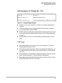
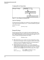
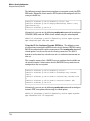
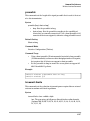
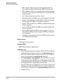
Advantages of Using the CLI
HP420#
Exec Level
HP420(config)#
Global Configuration Level
HP420(<context>)#
Context Configuration Levels (Ethernet, wireless)
Figure 2-1. Command Prompt Examples
■
Provides access to the complete set of the access point configuration
features.
■
Offers out-of-band access, through the RS-232 connection, or in-band
access using Telnet or Secure Shell.
■
Enables quick, detailed system configuration and management access to
system operators and administrators experienced in command prompt
interfaces.
■
Provides help at each level for determining available options and vari
ables.
CLI Usage
■
For information on how to use the CLI, refer to chapter 3, “Using the
Command Line Interface (CLI).”
■
To perform specific procedures (such as configuring IP addressing), use
the Contents listing at the front of the manual to locate the information
you need.
■
For monitoring and analyzing access point operation, refer to the appro
priate section in chapter 5, “General System Configuration.”
■
For information on individual CLI commands, refer to the Index or to the
online Help provided in the CLI interface.
2-3
Selecting a Management Interface
Advantages of Using the HP Web Browser Interface
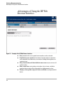
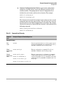
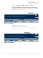
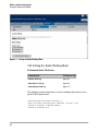
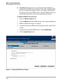
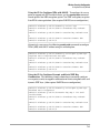
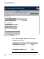
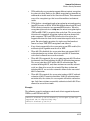
Advantages of Using the HP Web
Browser Interface
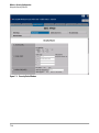
Figure 2-2. Example of the HP Web Browser Interface
2-4
■
Easy access to the access point from anywhere on the network
■
Familiar browser interface--locations of window objects consistent
with commonly used browsers, uses mouse clicking for navigation, no
terminal setup
■
Many features have all their fields in one screen so you can view all
values at once
■
More visual cues, using colors, status bars, device icons, and other
graphical objects instead of relying solely on alphanumeric values
■
Display of acceptable ranges of values available in configuration list
boxes
3
Using the Command Line Interface (CLI)
Contents
Overview . . . . . . . . . . . . . . . . . . . . . . . . . . . . . . . . . . . . . . . . . . . . . . . . . . . . . . 3-2
Accessing the CLI . . . . . . . . . . . . . . . . . . . . . . . . . . . . . . . . . . . . . . . . . . . . . . . 3-2
Direct Console Access . . . . . . . . . . . . . . . . . . . . . . . . . . . . . . . . . . . . . . . 3-2
Telnet Access . . . . . . . . . . . . . . . . . . . . . . . . . . . . . . . . . . . . . . . . . . . . . . . 3-3
Secure Shell Access . . . . . . . . . . . . . . . . . . . . . . . . . . . . . . . . . . . . . . . . . 3-3
Using the CLI . . . . . . . . . . . . . . . . . . . . . . . . . . . . . . . . . . . . . . . . . . . . . . . . . . . 3-4
Command Level at Logon . . . . . . . . . . . . . . . . . . . . . . . . . . . . . . . . . . . . . 3-4
Command Level Operation . . . . . . . . . . . . . . . . . . . . . . . . . . . . . . . . . . . 3-6
Operator Privileges . . . . . . . . . . . . . . . . . . . . . . . . . . . . . . . . . . . . . . 3-6
Manager Privileges . . . . . . . . . . . . . . . . . . . . . . . . . . . . . . . . . . . . . . . 3-6
How To Move Between Levels . . . . . . . . . . . . . . . . . . . . . . . . . . . . . . . . 3-8
Listing Commands and Command Options . . . . . . . . . . . . . . . . . . . . . . 3-9
Listing Commands Available at Any Command Level . . . . . . . . . . 3-9
Command Option Displays . . . . . . . . . . . . . . . . . . . . . . . . . . . . . . . 3-11
Configuration Commands and the Context Configuration Modes . . 3-12
3-1
Using the Command Line Interface (CLI)
Overview
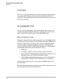
Overview
The CLI is a text-based command interface for configuring and monitoring the
access point. The CLI gives you access to the access point’s full set of
commands while providing the same password protection that is used in the
web browser interface.
Accessing the CLI
The CLI is accessed through the access point console. You can access the
console out-of-band by directly connecting a terminal device to the access
point, or in-band by using Telnet or a Secure Shell (SSH) client.
Direct Console Access
To connect a console directly to the access point, use a null-modem cable or
an HP serial cable, part number 5184-1894 (shipped with many HP ProCurve
switches). Connect the serial cable between a PC or VT-100 terminal to be
used as a console and the access point’s Console port. Configure the PC
terminal emulator as a DEC VT-100 (ANSI) terminal or use a VT-100 terminal,
and configure either one to operate with these settings:
•
9600 baud
•
8 data bits, 1 stop bit, no parity, and flow control set to None
•
For the Windows Terminal program, also disable (uncheck) the “Use
Function, Arrow, and Ctrl Keys for Windows” option
•
For the Hilgraeve HyperTerminal program, select the “Terminal keys”
option for the “Function, arrow, and ctrl keys act as” parameter
When correctly connected to the access point, press [Enter] to initiate the
console session.
For more information on connecting to the access point’s Console port, refer
to the Installation and Getting Started Guide.
3-2
Using the Command Line Interface (CLI)
Accessing the CLI
Telnet Access
To access the console through a Telnet session, first make sure the access
point is configured with an IP address and that it is reachable from the PC that
is running the Telnet session (for example, use a ping command to the access
point’s IP address).
Start the Telnet program on the PC using the access point’s IP address (or DNS
name).
telnet 10.11.12.195 [Enter]
Example of an IP address.
telnet HP420 [Enter]
Example of a DNS-type name.
Secure Shell Access
To access the console through an SSH session, SSH v2.0 client software must
be installed on the management station PC. The access point must also be
configured with an IP address and be reachable from the management station
PC (for example, use a ping command to the access point’s IP address).
Start the SSH program on the PC using the access point’s IP address (or DNS
name).
Note
ssh 10.11.12.195 [Enter]
Example of an IP address.
ssh HP420 [Enter]
Example of a DNS-type name.
The access point supports only SSH version 2.0.
After boot up, the SSH server needs about two minutes to generate host
encryption keys. The SSH server is disabled while the keys are being gener
ated.
For more information on the Secure Shell, see “Setting Management Access
Controls” on page 5-7.
3-3
Using the Command Line Interface (CLI)
Using the CLI
Using the CLI
The CLI commands are organized into the following levels:
Note
1.
Exec
2.
Global Configuration
3.
Context Configuration
CLI commands are not case-sensitive.
The access point supports two user account types, Manager and Operator.
When a CLI session is opened with an Operator user account, only a limited
number of commands are available. An Operator account can only view
system information from the Exec level, it cannot access CLI configuration
levels or make any changes to the access point configuration. Only a Manager
user account has access to all CLI commands at all levels and can make
changes to the system configuration.
When you use the CLI to make a configuration change, the access point
immediately saves the change to non-volatile memory. Whenever you reboot
the access point, all changes made since the last reboot are retained.
Command Level at Logon
By default, the access point provides a Manager user name for CLI access with
no password. There is no Operator account configured. To secure manage
ment access to the access point, you must set the Manager password. Without
a Manager password configured, anyone having serial port or Telnet access
to the access point can reach all CLI command modes.
Caution
HP strongly recommends that you configure a Manager password. If a Man
ager password is not configured, the access point is not password-protected,
and anyone having in-band or out-of-band access to the access point may be
able to compromise access point and network security.
For additional security, it is also possible to disable CLI management access
through the serial port or Telnet. For more information, see “Setting Manage
ment Access Controls” on page 5-7.
3-4
Using the Command Line Interface (CLI)
Using the CLI
When you log onto the access point CLI, you will be prompted to enter an
account user name and password. For example:
Ready
Username: admin
Password:
Password Prompt
Figure 3-1. Example of CLI Log-On Screen with Password
When you log onto the CLI using a Manager account, you see the following
command prompt:
HP420#_
When you log on using an Operator account, you see the following command
prompt:
HP420>_
Note
There is no CLI command to move directly from Operator privileges to
Manager privileges. You must log out of the CLI and use a Manager account
user name to log-on.
3-5
Using the Command Line Interface (CLI)
Using the CLI
Command Level Operation
Manager Privileges
1. Exec Level
2. Global Configuration Level
3. Context Configuration Level
Figure 3-2. Access Sequence for Command Levels
Operator Privileges
Operator privileges only allow you to examine the current configuration and
verify connectivity from the Exec level. A ">" character delimits the Operator
prompt. For example:
HP420>_
Operator prompt.
Manager Privileges
Manager privileges allow you to examine the current configuration, make
system configuration changes, and move between the three levels of access:
Exec, Global Configuration, and Context Configuration. (See figure 3-2.) A "#"
character delimits the Manager prompt. For example:
HP420#_
■
Exec level: Allows you to examine the current configuration, perform
basic system-level actions, reset the access point, and move to the config
uration access levels. The prompt for the Exec level contains only the
system name and the "#" delimiter, as shown above.
■
Global Configuration level: Enables you to make configuration
changes to the access point’s software features. The prompt for the Global
Configuration level includes the system name and "(config)". To select
this level, enter the config command at the Exec prompt. For example:
HP420# _
HP420(config)#_
3-6
Manager prompt.
Enter config at the Manager prompt.
The Global Config prompt.
Using the Command Line Interface (CLI)
Using the CLI
■
Context Configuration level: Enables you to make configuration
changes in a specific context, such as the Ethernet interface or the
wireless interface. The prompt for the Context Configuration level
includes the system name and the selected context. For example:
HP420(if-ethernet)#
HP420(if-wireless-g)#
The Context level is useful, for example, if you want to execute several
commands directed at the same interface. To select this level, enter the
specific context at the Global Configuration level prompt. For example,
to select the context level for the Ethernet interface, you would enter the
following command:
HP420(config)#interface ethernet
HP420(if-ethernet)#
Table 3-1.
Command
Level
Command Level Hierarchy
Example of Prompt and Permitted Operations
Manager Privileges
Exec
Level
HP420#
Perform system-level actions such as system control,
monitoring, and diagnostic commands. For a list of
available commands, enter ? at the prompt.
Global
HP420(config)#
Configuration
Level
Execute configuration commands. For a list of
available commands, enter ? at the prompt.
Context
HP420(config-mgmt)
Configuration
HP420(if-ethernet)#
Level
Execute context-specific configuration commands,
such as a particular access point interface. This is
useful for entering a series of commands for the same
context. For a list of available commands, enter ? at
the prompt.
HP420(if-wireless-g)#
HP420(if-wireless-g-ssid-1)#
3-7
Using the Command Line Interface (CLI)
Using the CLI
How To Move Between Levels
Change in Levels
Example of Prompt, Command, and Result
Exec level
to
Global configuration
level
HP420#config
HP420(config)#
Global configuration HP420(config)#interface ethernet
level
HP420(if-ethernet)#
to a
Context configuration
level
Move from any level HP420(if-ethernet)#end
to the preceding level HP420(config)#end
HP420#
Move from any level
to the Exec level
HP420(if-ethernet)#exit
HP420#
—or—
HP420(config)#exit
HP420#
Changing Parameter Settings. Regardless of which interface is used (CLI,
or web browser interface), the most recently configured version of a param
eter setting overrides any earlier settings for that parameter. For example, if
you use the web interface to configure an IP address of “X” for the Ethernet
interface and later use the CLI to configure a different IP address of “Y”, then
“Y” replaces “X” as the IP address for the Ethernet interface.
3-8
Using the Command Line Interface (CLI)
Using the CLI
Listing Commands and Command Options
At any command level you can:
■
List all of the commands available at that level
■
List the options for a specific command
Listing Commands Available at Any Command Level
At a given command level you can list and execute the commands that level
offers. For example, at the Exec level, you can list and execute only the Exec
level commands; and at the Configuration level, you can list and execute the
commands available only to Configuration levels.
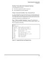
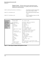
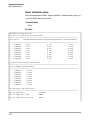
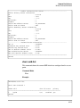
Type "?" To List Available Commands. Typing the ? symbol lists the
commands you can execute at the current level. For example, typing ? at the
Exec level produces this listing:
HP420#?
Exec commands:
bootfile
Specify Application Bootfile
configure Enter configuration mode
copy
Copy from one file to another
country
Set the country code
delete
Delete a file
dir
List files on a file system
exit
Exit from the EXEC
help
Description of the help system
ping
Send echo messages
reset
Reset this system
show
Show information
HP420#
Figure 3-3. Example of the Exec Level Command Listing
3-9
Using the Command Line Interface (CLI)
Using the CLI
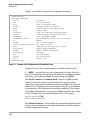
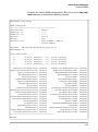
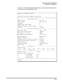
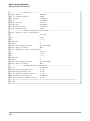
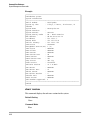
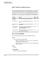
Typing ? at the Global Configuration level produces this listing:
HP420(config)#?
Configure commands:
802.1x
end
exit
filter
help
iapp
interface
logging
management
management-vlanid
no
prompt
radius-accounting-server
show
snmp-server
snmpv3
sntp-server
svp
system
vlan
HP420(config)#
Set 802.1x
End config mode
Exit to previous mode
Bridge protocol filtering
Description of the help system
Enable IAPP
Into the interface configure mode
Modify message logging facilities
Enter management mode
Set Management VLAN ID for AP <1-4094>
Negate
Set system's prompt
Set
radius server
Show general configuration status
Modify SNMP parameters
Modify SNMPv3 parameters
Set SNTP
Set SVP Enable
Set system name
Enable Vlan
Figure 3-4. Example of the Configuration-Level Command Listing
Typing? at the the Context Configuration level produces similar results.
If - - MORE - - appears, there are more commands in the listing. To list the
next set of commands, press the Space bar. To list the remaining commands
one-by-one, repeatedly press [Enter]. To stop the listing, type [Ctrl] [C].
Use [Tab] To Complete a Command Word. You can use [Tab] to quickly
complete the current word in a command. To do so, type one or more
consecutive characters for a command and then press [Tab] (with no spaces
allowed). The CLI completes the current word (if you have typed enough of
the word for the CLI to distinguish it from other possibilities). For example,
at the Global Configuration level, if you press [Tab] immediately after typing
"f", the CLI displays the command that begins with "f". For example:
HP420(config)#f[Tab]
HP420(config)#filter
Use Shorthand Entries. You can abbreviate commands and options as long
as they contain enough letters to be distinguished from any other currently
available commands or options.
3-10
Using the Command Line Interface (CLI)
Using the CLI
Command Option Displays
Conventions for Command Option Displays. When you use the CLI to
list options for a particular command, you will see one or more of the following
conventions to help you interpret the command data:
■
Braces (< >) indicate a required choice.
■
Square brackets ([]) indicate optional elements.
■
Vertical bars (|) separate alternative, mutually exclusive options in a
command.
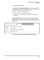
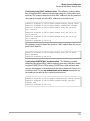
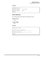
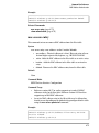
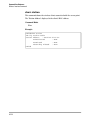
Listing Command Options. You can use the CLI to remind you of the
options available for a command by entering command keywords followed
by?. For example, suppose you want to see the command options for config
uring SNMP:
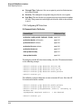
This example displays the command options
for configuring SNMP on the access point.
HP420(config)#snmp-server ?
community Set SNMP community string
contact
Set text for mib sysContact
enable
Enable Server
host
Specify hosts to receive SNMP
location
Text for mib object sysLocation
trap
Enable SNMP traps
HP420(config)#snmp-server
Figure 3-5. Example of How To List the Options for a Specific Command
3-11
Using the Command Line Interface (CLI)
Using the CLI
Configuration Commands and the Context
Configuration Modes
You can execute basic configuration commands in the global configuration
mode. However, you must use a context mode to execute context-specific
commands.
The configuration options include management and interface (ethernet or
wireless) context modes:
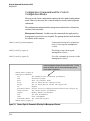
Management Context . Includes specific commands that apply only to
management access to the access point. The prompt for this mode includes
the identity of the context:
HP420(config)#management
Command executed at configuration
level for entering the management
context.
HP420(config-mgmt)#
Resulting prompt showing the
management context.
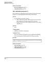
HP420(config-mgmt)#?
Lists the commands you can use in the
management context.
In the management context, the commands in the "?" listing
show the context-specific commands that apply only to
access point management.
HP420(config-mgmt)#?
Configure commands:
cli
Set Command Line Interface parameters
end
End config mode
exit
Exit to previous mode
http
Set IP HTTP server configuration
https
Set IP HTTP secure server configuration
no
Negate
password-admin Assign the privileged password myself(max length:16)
reset-button
Set reset button parameters
snmpv3
Modify SNMPv3 parameters
ssh
Set SSH Parameters
user
User management
username-admin Set username myself
HP420(config-mgmt)#
Figure 3-6. Context-Specific Commands Affecting the Management Context
3-12
Using the Command Line Interface (CLI)
Using the CLI
Ethernet Context . Includes interface-specific commands that apply only
to the Ethernet interface. The prompt for this mode includes the identity of
the Ethernet interface:
HP420(config)#interface ethernet
Command executed at configuration
level for entering Ethernet interface
context.
HP420(if-ethernet)#
Resulting prompt showing Ethernet
interface context.
HP420(if-ethernet)#?
Lists the commands you can use in the
Ethernet interface context.
In the Ethernet context, the commands in the "?" listing show
the context-specific commands that affect only the
Ethernet interface.
HP420(if-ethernet)#?
Configure commands:
dns
DNS Server settings
end
Return to previous mode
exit
Exit to the EXEC mode
help
Description of the help system
ip
Set IP
no
Negate
show
Show Ethernet interface
shutdown
Shutdown the interface
speed-duplex Set ethernet speed/duplex mode
HP420(if-ethernet)#
Figure 3-7. Context-Specific Commands Affecting Ethernet Interface Context
3-13
Using the Command Line Interface (CLI)
Using the CLI
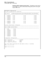
Wireless Context . Includes wireless-specific commands that apply
globally to the wireless interface. The prompt for this mode includes the
identity of the wireless interface:
HP420(config)#interface wireless g
Command executed at configuration
level to enter wireless context.
HP420(if-wireless-g)#
Resulting prompt showing wireless
context.
HP420(if-wireless-g)#?
Lists commands you can use in the
wireless context.
In the wireless
context, the
commands in
the "?" listing
show the
commands that
affect only the
wireless
interface.
HP420(if-wireless-g)#?
antenna-mode
ap-detection
beacon-interval
channel
description
dtim-period
end
exit
fragmentation-length
help
max-association
multicast-data-rate
no
preamble
radio-mode
rts-threshold
show
shutdown
slot-time
speed
ssid
transmit-limits
transmit-power
HP420(if-wireless-g)#
Set antenna mode
Configure rogue ap parameters
Set beacon interval
Set channel
Set description
Set DTIM
End config mode
Exit to previous mode
Set fragment length
Description of the help system
Maximum association munber
Set multicast data rate
Negate
Preamble length
Set 802.11g mode
Rts threshold
Show wireless interface
Stop radio
Fix the slot time
Speed
Create and go to a particular SSID
Set detachable antenna gain attenuation
Transmit power
Figure 3-8. Context-Specific Commands Affecting Wireless Context
3-14
Using the Command Line Interface (CLI)
Using the CLI
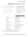
Wireless SSID Context . Includes specific commands that apply only to
the SSID wireless interface. The prompt for this mode includes the identity of
the wireless interface:
HP420(config)#interface wireless g
Command executed at configuration
level to enter wireless context.
HP420(if-wireless-g)#ssid index 1
Command executed at wireless
context level to enter SSID wireless
context.
HP420(if-wireless-g-ssid-1)#?
Resulting prompt showing the SSID
wireless context.
HP420(if-wireless-g-ssid-1)#?
Lists commands you can use in the
SSID wireless context.
In the wireless context, the commands in the "?"
listing show the commands that affect only the
wireless interface.
HP420(if-wireless-g-ssid-1)#?
802.1x closed-system
enable end exit help mac-access mac-authentication
no pmksa-lifetime
pre-authentication
primary radius-authentication-server
security-suite
show ssid-name transmit-key-wep
vlan-ID wpa-preshared-key
HP420(if-wireless-g-ssid-1)#
Set 802.1x
Set Closed System
Enable intreface
End config mode
Exit to previous mode
Description of the help system
Local MAC filtering
Set RADIUS MAC Authentication
Negate
Set pmksa-lifetime
Set WPA2.0 Pre-authentication status
Set this SSID as primary
Set
radius authentication server
security setting
Show wireless interface
Configure SSID name
Set wep-key
Set default vlan ID
WPA enter Pre-shared key
Figure 3-9. Context-Specific Commands Affecting the SSID Wireless Context
3-15
Using the Command Line Interface (CLI)
CLI Control and Editing
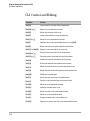
CLI Control and Editing
3-16
Keystrokes
Function
[Ctrl] [A]
Jumps to the first character of the command line.
[Ctrl] [B] or [<]
Moves the cursor back one character.
[Ctrl] [D]
Deletes the character at the cursor.
[Ctrl] [E]
Jumps to the end of the current command line.
[Ctrl] [F] or [>]
Moves the cursor forward one character.
[Ctrl] [I]
Completes the current command word (same as using [Tab]).
[Ctrl] [K]
Deletes from the cursor to the end of the command line.
[Ctrl] [L], or [Ctrl] [R]
Repeats current command line on a new line.
[Ctrl] [N] or [v]
Enters the next command line in the history buffer.
[Ctrl] [P] or [^]
Enters the previous command line in the history buffer.
[Ctrl] [Q]
Enables the output of command text on the console.
[Ctrl] [S]
Disables the output of command text on the console.
[Ctrl] [T]
Moves the character at the cursor one position to the left.
[Ctrl] [U]
Deletes from the cursor to the beginning of the command line.
[Ctrl] [W]
Deletes the last word typed.
[Ctrl] [Y]
Recalls the most recent entry in the delete buffer.
[Ctrl] [Z]
Exits the current command level to the previous level.
[Esc] [B] *
Moves the cursor backward one word.
[Esc] [C] *
Capitalizes the word at the cursor.
[Esc] [D] *
Deletes from the cursor to the end of the word.
[Esc] [F] *
Moves the cursor forward one word.
[Esc] [L] *
Changes the word at the cursor to lowercase.
[Esc] [U] *
Capitalizes characters from the cursor to the end of the word
Using the Command Line Interface (CLI)
CLI Control and Editing
Keystrokes
Function
[Esc] [Y] *
Recalls the next buffer entry in the delete buffer.
[Ctrl] [H], [Delete], or Deletes the first character to the left of the cursor in the command
line.
[Backspace]
* Multiple keystrokes using the ESc key require it to be released before each keystroke.
3-17
Using the Command Line Interface (CLI)
CLI Control and Editing
— This page is intentionally unused. —
3-18
4
Using the HP Web Browser Interface
Contents
Overview . . . . . . . . . . . . . . . . . . . . . . . . . . . . . . . . . . . . . . . . . . . . . . . . . . . . . . 4-2
General Features . . . . . . . . . . . . . . . . . . . . . . . . . . . . . . . . . . . . . . . . . . . . . . . 4-3
Starting a Web Browser Interface Session with the Access Point . . . . . . . 4-4
Description of Browser Interface . . . . . . . . . . . . . . . . . . . . . . . . . . . . . . . . . . 4-5
The Home Page . . . . . . . . . . . . . . . . . . . . . . . . . . . . . . . . . . . . . . . . . . . . . 4-5
Support URL . . . . . . . . . . . . . . . . . . . . . . . . . . . . . . . . . . . . . . . . . . . . . . . 4-6
Online Help for the HP Web Browser Interface . . . . . . . . . . . . . . . . . . 4-7
Web Browser Interface Logout . . . . . . . . . . . . . . . . . . . . . . . . . . . . . . . . 4-7
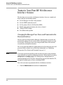
Tasks for Your First HP Web Browser Interface Session . . . . . . . . . . . . . . 4-8
Changing the Manager User Name and Password in the Browser Interface . . . . . . . . . . . . . . . . . . . . . . . . . . . . . . . . . . . . . . . . . . . . . . . . . . . 4-8
If You Lose the User Name or Password . . . . . . . . . . . . . . . . . . . 4-10
Setting SNMP Community Names . . . . . . . . . . . . . . . . . . . . . . . . . . . . . 4-10
Setting the Primary SSID . . . . . . . . . . . . . . . . . . . . . . . . . . . . . . . . . . . . 4-12
Setting the Radio Channel . . . . . . . . . . . . . . . . . . . . . . . . . . . . . . . . . . . 4-13
Configuring TCP/IP Settings . . . . . . . . . . . . . . . . . . . . . . . . . . . . . . . . . 4-14
Configuring Security Settings . . . . . . . . . . . . . . . . . . . . . . . . . . . . . . . . 4-16
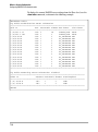
Status Reporting Features . . . . . . . . . . . . . . . . . . . . . . . . . . . . . . . . . . . . . . . 4-18
The AP Status Window . . . . . . . . . . . . . . . . . . . . . . . . . . . . . . . . . . . . . . 4-18
Station Status . . . . . . . . . . . . . . . . . . . . . . . . . . . . . . . . . . . . . . . . . . . . . . 4-21
Event Log . . . . . . . . . . . . . . . . . . . . . . . . . . . . . . . . . . . . . . . . . . . . . . . . . 4-23
The Status Bar . . . . . . . . . . . . . . . . . . . . . . . . . . . . . . . . . . . . . . . . . . . . . 4-24
Neighbor AP Detection . . . . . . . . . . . . . . . . . . . . . . . . . . . . . . . . . . . . . .
Web: Configuring AP Detection . . . . . . . . . . . . . . . . . . . . . . . . . . .
Web: Viewing Detected Neighbor APs . . . . . . . . . . . . . . . . . . . . .
CLI: Configuring AP Detection . . . . . . . . . . . . . . . . . . . . . . . . . . . .
4-24
4-25
4-27
4-28
4-1
Using the HP Web Browser Interface
Overview
Overview
The HP web browser interface built into the access point lets you easily access
the access point from a browser-based PC on your network. This lets you do
the following:
■
Make configuration changes to the access point
■
Control access to the management interface by configuring a user name
and password
■
Maintain access security for wireless clients using WPA or WEP shared
keys
■
Encrypt data communications between clients and access points using
various algorithms, including WEP, TKIP, or AES
■
Optimize your network uptime by using the System Log
This chapter covers the following:
■
General features (page 4-3)
■
Starting a web browser interface session (page 4-4)
■
Tasks for your first web browser interface session (page 4-8)
■
■
4-2
•
Configuring a user name and password for management access in the
web browser interface (page 4-8)
•
Set the SNMP community names (page 4-10)
•
Set the primary Service Set Identifier (page 4-12)
•
Enable radio communications and select a channel (page 4-13)
•
Changing IP settings (page 4-14)
•
Setting wireless network security (page 4-16)
•
Getting access to online help for the web browser interface (page 4-7)
Description of the web browser interface
•
The Home Page (page 4-5)
•
The Support URL (page 4-6)
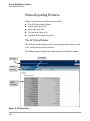
•
The Help button (page 4-7)
•
The Logout button (page 4-7)
Status Reporting Features
•
The AP Status window (page 4-18)
•
Station status (page 4-21)
•
Event logs (page 4-23)
•
The Status bar (page 4-24)
Using the HP Web Browser Interface
General Features
•
Neighbor access point detection (page 4-24)
General Features
The access point includes these web browser interface features:
Access Point Configuration:
•
System identification
•
IP settings via manual configuration or DHCP
•
RADIUS accounting server identification
•
Filter control between wireless clients, between wireless clients and
the management interface, or for specified protocol types
•
SNMP community strings, trap managers, and SNMPv3 settings
•
Usernames and passwords
•
Firmware upgrade and system reset
•
System log server and log message levels
•
SNTP client and manual clock configuration
•
Neighbor access point detection
Access Point Radio Interface:
•
Radio signal parameters
•
Up to eight service set identifier (SSID) interfaces
•
RADIUS client identification
•
Wireless client authentication via IEEE 802.1X
•
Wireless client security, including WEP, WPA, and WPA2
Access Point status
•
System configuration
•
Wireless configuration
•
S
tation status
•
Event logs
4-3
Using the HP Web Browser Interface
Starting a Web Browser Interface Session with the Access Point
Starting a Web Browser Interface
Session with the Access Point
You can start a web browser session using a standalone web browser on a
network connection from a PC in the following ways:
•
Directly connected to your network
•
Connected through remote access to your network
This procedure assumes that you have a supported web browser installed on
your PC or workstation, and that an IP address has been configured on the
access point. If you are using a Domain Name Server (DNS), your device may
have a name associated with it (for example, hp420) that you can type in the
Location or Address field instead of the IP address. Using DNS names typically
improves browser performance. See your network administrator for any name
associated with the access point. (For more information on assigning an IP
address, refer to “IP Configuration” on page 4-15.)
The operating systems, web browsers, and Java support required to manage
the access point through the browser interface are listed in the following
table::
Operating System
Internet
Explorer
Windows 2000 Professional 5.01
Windows 2000 Professional 5.0
SP4
1, 2
Netscape
Mozilla
Mozilla
Firefox
7.02
7.12
1.7.32
1.0PR2
7.02
2
2
2
1.7.3
1.0PR
7.1
Windows 2000 Server SP4
5.01, 2
7.02
7.12
Windows XP Professional
version 2002 SP1
6.01, 2
7.02
7.12
1.7.32
1.0PR2
Windows XP Professional
version 2002 SP2
6.01, 2
7.02
7.12
1.7.32
1.0PR2
Windows 2003 Server
6.01, 2
7.02
7.12
1.7.32
1.0PR2
Mac OS 9.2
Linux kernal 2.4.18.44
4-4
Java
1 Microsoft Java Virtual Machine
2
5.00.3810.
Sun Java 2 Runtime
Environment Standard Edition
v1.4.1 and v1.4.2
1.0PR2
7.0
1.0.1
Sun Java 2 Runtime Environment
Standard Edition v1.4.2
Using the HP Web Browser Interface
Description of Browser Interface
Note:
Access point management can be limited to access from the Ethernet inter
face. For more on this feature, see “Setting up Filter Control” on page 5-58.
Type the IP address (or DNS name) of the access point in the browser Location
or Address field and press [Enter]. (It is not necessary to include http://.)
10.11.12.195 [Enter]
Example of an IP address.
HP420 [Enter]
Example of a DNS-type name.
Alternatively, the access point also supports a secure Web (HTTPS) browser
connection. In this case, type https:// followed by the IP address (or DNS name)
in the browser Location or Address field and press [Enter].
Note
https://10.11.12.195 [Enter]
Example of an IP address.
https://HP420 [Enter]
Example of a DNS-type name.
To ensure proper screen refresh when using Internet Explorer with Windows
XP, be sure that the browser options are configured as follows: Under the
menu “Tools / Internet Options / Temporary Internet Files / Settings,” the
setting for item “Check for newer versions of stored pages” should be set to
“Automatically.”
Description of Browser Interface
Browser elements covered in this section include:
■
The Home Page (below)
■
The Support URL (page 4-6)
■
The Help button (page 4-7)
■
The Logout button (page 4-7)
The Home Page
The home page is the entry point for the web browser interface.The following
figure identifies the various parts of the screen.
4-5
Using the HP Web Browser Interface
Description of Browser Interface
Active Tab
Tab Bar
World Wide Web site for
Hewlett-Packard’s
networking products
Figure 4-1. The Home Page
Support URL
The home page for the access point’s web browser interface is the Support tab.
This page provides the following URL:
http://www.hp.com/go/hpprocurve
which is the World Wide Web site for Hewlett-Packard’s networking products.
Click on the link on this page and you can get to support information regarding
your access point, including white papers, firmware updates, and more.
4-6
Using the HP Web Browser Interface
Description of Browser Interface
Online Help for the HP Web Browser Interface
Online Help is available for the web browser interface. You can use it by
clicking on the question mark button in the upper-right corner of any of the
web browser interface screens.
The Help Button
Figure 4-2. The Help Button
Web Browser Interface Logout
To finish any web browser interface session, click the [Logout] button in the
upper-right corner of any of the web browser interface screens.
The Logout Button
Figure 4-3. The Logout Button
4-7
Using the HP Web Browser Interface
Tasks for Your First HP Web Browser Interface Session
Tasks for Your First HP Web Browser
Interface Session
The first time you access the web browser interface, there are a number of
basic tasks that you should perform:
■
Set the Manager user name and password
■
Set the SNMP community names
■
Set the primary Service Set Identifier (SSID)
■
Enable radio communications and select a channel
■
Change TCP/IP settings
■
Set radio security options
Changing the Manager User Name and Password in the
Browser Interface
You may want to change both the Manager (Administrator) user name and
password to enhance access security for the management interface on your
access point. The Manager user name and password allows full read/write
access to the web browser interface.
The access point also allows the configuration of an Operator user name and
password with read-only access. For more information, see “Modifying
Management User Names and Passwords” on page 5-3.
Note
If you want security beyond that achieved with user names and passwords,
you can disable access to the web browser interface. This is done by executing
no http server and no https server at the Management Configuration level
command prompt in the CLI. Then, management access is only from the CLI,
through the console port or Telnet, or through SNMP.
To set the user name or password with the web browser interface:
1.
4-8
Click the Administration tab and then the [User] button.
Using the HP Web Browser Interface
Tasks for Your First HP Web Browser Interface Session
Figure 4-4. The User Window
2. In the Edit Existing User section, click in the Username box for “admin” and
enter a new user name. Then, click in the Password box to enter a new
password.
Both the user name and password can be from 3 to 16 printable ASCII
characters.
3.
Note
Click on [Update] to activate the user name and password.
The Manager (Administrator) user name and password you assign in the web
browser interface will overwrite the previous settings assigned in either the
web browser interface or the access point console. That is, the most recently
assigned user name and password are immediately effective for the access
point, regardless of which interface was used to assign these parameters.
The Manager user name and password are used to control access to the CLI
and web browser management interfaces for the access point. Once set, you
will be prompted to supply the user name and password every time you try to
access the access point through these interfaces.
4-9
Using the HP Web Browser Interface
Tasks for Your First HP Web Browser Interface Session
If You Lose the User Name or Password
If you lose the Manager user name or password, you can clear them by pressing
the Reset button on the back of the access point for at least five seconds. This
action deletes the password and resets the user name to the factory default
settings for all of the access point’s interfaces. All configuration information
is reset to the factory default values, including:
Caution
■
User names and passwords
■
Console event log (cleared)
■
Network counters (reset to zero)
■
Configured IP address
■
SNMP Configuration
The Reset button is provided for your convenience, but if you are concerned
with the security of the access point configuration and operation, you should
disable it. See “Setting Management Access Controls” on page 5-7.
Setting SNMP Community Names
You can manage the access point form a network management station running
a Simple Network Management Protocol (SNMP) management application
such as HP ProCurve Manager.
The access point SNMP agent supports SNMP versions 1, 2c, and 3. Manage
ment access from SNMP v1 or v2c stations is controlled by community names.
To communicate with the access point, an SNMP v1 or v2c management
station must first submit a valid community name for authentication. The
default community names are “public” for read-only access and “private” for
read/write access. If you intend to support SNMP v1 or v2c managers, it is
recommended that you change the default community names to prevent
unauthorized access.
If you intend to support SNMP v3 managers, you need to configure user names,
set specific security levels, and assigned them to a group. For more informa
tion, see “Web: Configuring SNMP v3 Users” on page 5-24.
Note
4-10
For secure SNMP access to the access point, you can enable the SNMPv3 Only
feature that prevents access from SNMP v1 and v2c clients. For more infor
mation, see “Configuring SNMP” on page 5-19.
Using the HP Web Browser Interface
Tasks for Your First HP Web Browser Interface Session
To change the default community names for SNMP v1 or v2c management
access, follow these steps:
1. Select the Configuration tab.
2. Click the [SNMP] button.
3. For SNMP State, select Enable to enable SNMP management.
4. For SNMPv3 Only, select Disable to enable access from SNMP v1 and v2c
clients.
5. Type text strings to replace the default community names for read-only
and read/write access.
6. Click the [Apply Changes] button.
Figure 4-5. Setting SNMP Community Names
4-11
Using the HP Web Browser Interface
Tasks for Your First HP Web Browser Interface Session
Setting the Primary SSID
A Service Set IDentifier (SSID) is a recognizable text string that identifies a
wireless network. All wireless clients that want to connect to a network
through an access point must set their SSIDs to match that of the access point.
The Access Point 420 supports up to eight SSID interfaces. This allows traffic
to be separated for different user groups using a single access point that
services one area. For each SSID interface, different security settings, VLAN
assignments, and other parameters can be applied.
The first SSID interface created on the access point is set as the primary. The
primary SSID is the only SSID broadcast in the access point’s beacon frames.
You should set the SSID for the primary interface before creating secondary
interfaces.
To set the access point’s primary SSID, click the Wireless Interfaces tab and
then for the primary SSID, click the [Modify] button. Enter a text string up to
32 characters in the SSID Name box. Click the [Apply Changes] button to save the
setting.
Figure 4-6. Setting the Primary SSID
4-12
Using the HP Web Browser Interface
Tasks for Your First HP Web Browser Interface Session
Setting the Radio Channel
The access point’s radio channel settings are limited by local regulations,
which determine the number of channels that are available. You can manually
set the access point’s radio channel or allow it to automatically select an
unoccupied channel.
Note
If you are using the worldwide product, J8131A, before configuring radio
settings on the access point, you must first use the CLI to set the Country Code
so that the radio channels used conform to your local regulations. See “Setting
the Country Code” on page 6-3.
The access point uses the configured radio channel to communicate with
wireless clients. When multiple access points are deployed in the same area,
be sure to choose a channel separated by at least five channels to avoid having
the channels interfere with each other. You can deploy up to three access
points in the same area (for example, channels 1, 6, 11).
1.
Click the Configuration tab, and then click the [Port/Radio Settings] button.
2.
Select the Working Mode.
3.
Click the [Radio Mode Change] button.
Figure 4-7. Changing the Radio Working Mode
4-13
Using the HP Web Browser Interface
Tasks for Your First HP Web Browser Interface Session
4. For the Radio Status, clear the Shutdown box to enable radio communica
tions.
5. Select the radio channel from the scroll-down box, or mark the Enable
radio button for Auto Channel Select.
6. Click the [Apply Changes] button to save the settings.
Figure 4-8. Radio Channel Selection
Configuring TCP/IP Settings
You can use the web browser interface to manage the access point only if it
already has an IP address that is reachable through your network. You can set
an initial IP address for the access point by using the CLI interface. After you
have network access to the access point, you can then use the web browser
interface to modify the initial IP configuration.
1. Click the Configuration tab, and then click the [IP Configuration] button.
2. Select either Obtain the IP Address from the DHCP Server or Use the Static IP
Address below.
4-14
Using the HP Web Browser Interface
Tasks for Your First HP Web Browser Interface Session
3. If you select to use a static IP address, you must manually enter the IP
address and subnet mask.
4. If a management station exists on another network segment, enter the IP
address of a gateway that can route traffic between these segments.
5. Enter the IP address for the primary and secondary DNS servers to be
used for host-name to IP address resolution.
6. Click the [Apply Changes] button.
Note
If you change the IP address using the web interface, you must log in again
using the new address.
Figure 4-9. IP Configuration
4-15
Using the HP Web Browser Interface
Tasks for Your First HP Web Browser Interface Session
Configuring Security Settings
The Primary SSID is configured as “open system” by default and secondary
SSIDs are all “closed system.” Secondary SSIDs cannot be configured as “open
system.” The Primary SSID can be configured as “closed system,” if the user
wants. Wireless clients can read the Primary SSID from the access point’s
beacon frame. If the “closed system” option is selected when configuring the
access point, the Primary SSID is not broadcast in the beacon frame. For more
secure data transmissions, the access point provides client authentication and
data encryption based on shared keys that are distributed to all stations.
Wired Equivalent Privacy (WEP) is implemented to provide a basic level of
security, preventing unauthorized access to the network and encrypting data
transmitted between wireless clients and the access point.
To implement WEP and set up shared keys, follow these steps:
1. Click the Wireless Interfaces tab and then the [Modify] button for the
primary SSID interface.
2. Click the [Security Suite] button.
3. Select the wizard option Static WEP.
4. Select the key length to be used by all clients, 64, 128, or 152 bit.
5. For the Key Index, select one key to be used for the SSID interface.
6. Select the Key Type, Hex or Ascii.
7. Enter one key conforming to the length and type already selected.
8. Click the [Apply Changes] button.
WEP is the security protocol initially specified in the IEEE 802.11 standard
for wireless communications. While WEP provides a margin of security for
environments with light network traffic, it is not sufficient for enterprise use
where highly-sensitive data is transmitted.
For more robust wireless security, you should consider implementing other
features supported by the access point. Wi-Fi Protected Access (WPA) and
IEEE 802.1X provide improved data encryption and user authentication. See
“Wireless Security Configuration” on page 7-1.
4-16
Using the HP Web Browser Interface
Tasks for Your First HP Web Browser Interface Session
Figure 4-10. Security Settings
4-17
Using the HP Web Browser Interface
Status Reporting Features
Status Reporting Features
Browser elements covered in this section include:
■
The AP Status window (below)
■
Station status (page 4-21)
■
Event logs (page 4-23)
■
The Status bar (page 4-24)
■
Neighbor AP Detection (page 4-24)
The AP Status Window
The AP Status window displays basic system configuration settings, as well
as the settings for the wireless interface.
The following figure identifies the various parts of the AP Status window.
Status Bar
Tab Bar
Button Bar
Current
Status
Information
Figure 4-11. AP System Status
4-18
Active Tab
Using the HP Web Browser Interface
Status Reporting Features
AP System Configuration. The AP System Configuration table displays the
basic system configuration settings:
■
System Up Time: Length of time the access point has been up.
■
MAC Address: The physical layer address for the Ethernet port interface.
■
System Name: Name assigned to this system.
■
System Contact: Administrator responsible for the system.
■
DHCP Status: Shows if IP configuration is via a DHCP server.
■
IP Address: IP address of the management interface for this device.
■
IP Default Gateway: IP address of the gateway router between this
device and management stations that exist on other network segments.
■
HTTP Server: Shows if management access via HTTP is enabled.
■
HTTP Server Port: Shows the TCP port used by the HTTP interface.
■
HTTP Secure Server: Shows if management access via secure HTTP is
enabled.
■
HTTP Secure Server Port: Shows the TCP port used by the secure HTTP
interface.
■
Secure Shell Server: Shows if management access via Secure Shell
(SSH) is enabled.
■
Secure Shell Port: Shows the TCP port used by the SSH server.
■
Telnet Server: Shows if management access via Telnet is enabled.
■
Country: Indicates the access point’s current Country Code setting.
■
Version: Shows the version number for the runtime software.
4-19
Using the HP Web Browser Interface
Status Reporting Features
Figure 4-12. AP Wireless and Ethernet Interface Status
AP Wireless Configuration. The AP Wireless Configuration table displays
the following wireless settings for each SSID interface:
4-20
■
No.: The index number of a configured SSID interface.
■
SSID: The service set identifier that identifies this SSID interface.
■
Radio: Indicates if the access point is operating in 802.11b, 802.11g, or
mixed (b &g) mode.
■
Status: Indicates if the access point radio is enabled or disabled.
■
Auto Channel: Indicates if the access point automatically selects an
unoccupied radio channel.
■
Channel: The radio channel through which the access point communi
cates with wireless clients.
■
Encryption: Shows if data encryption is enabled or disabled.
■
Auth. Type: Shows if open system or shared key authentication is used.
■
802.1x: Shows if IEEE 802.1X access control for wireless clients is
enabled.
Using the HP Web Browser Interface
Status Reporting Features
AP Ethernet Configuration. The AP Ethernet Configuration table displays
the following ethernet interface settings:
■
IP Subnet Mask: The mask that identifies the host address bits used for
routing to specific subnets.
■
Primary DNS Server: The IP address of the primary Domain Name
Server on the network.
■
Secondary DNS Server: The IP address of the secondary Domain Name
Server on the network.
■
Speed-Duplex: The operating speed and duplex mode of the access
point’s RJ-45 Ethernet interface.
Station Status
The Station Status window shows the wireless clients currently associated
with the access point.
Figure 4-13. The Station Status Window
The Station Configuration table displays the following information:
■
Station Address: The MAC address of the wireless client.
■
Authenticated: Shows if the station has been authenticated. The two
basic methods of authentication supported for 802.11 wireless networks
are “open system” and “shared key.” Open-system authentication accepts
4-21
Using the HP Web Browser Interface
Status Reporting Features
any client attempting to connect to the access point without verifying its
identity. The shared-key approach uses Wired Equivalent Privacy (WEP)
to verify client identity by distributing a shared key to stations before
attempting authentication.
4-22
■
Associated: Shows if the station has been successfully associated with
the access point. Once authentication is completed, stations can associate
with the current access point, or reassociate with a new access point. The
association procedure allows the wireless system to track the location of
each mobile client, and ensures that frames destined for each client are
forwarded to the appropriate access point.
■
Forwarding Allowed: If 802.1X is being used shows if the station has
passed 802.1X authentication and is now allowed to forward traffic to the
access point. If authentication is not required this value is TRUE for all
clients.
■
Key Type: Displays one of the following:
•
none: The client is not using encryption keys.
•
static-wep: The client is using static WEP keys for encryption.
•
dynamic-wep: The client is using 802.1X authentication with
dynamic WEP keys.
•
wpa-psk-tkip: The client is using Wi-Fi Protected Access (pre-shared
key mode) with PSK keys. TKIP is used for the unicast and multicast
cipher.
•
wpa-psk-aes: The client is using Wi-Fi Protected Access (pre-shared
key mode) with PSK keys. AES is used for the unicast and multicast
cipher.
•
wpa-psk-tkip-wep: The client is using Wi-Fi Protected Access (preshared key mode) with PSK keys. TKIP is used for the unicast cipher
and WEP is used for the multicast cipher.
•
wpa-psk-aes-tkip: The client is using Wi-Fi Protected Access (preshared key mode) with PSK keys. AES is used for the unicast cipher
and TKIP is used for the multicast cipher.
•
wpa-tkip: The client is using Wi-Fi Protected Access (dynamic mode)
with TKIP keys. TKIP is used for the unicast and multicast cipher.
•
wpa-aes: The client is using Wi-Fi Protected Access (dynamic mode)
with AES keys. AES is used for the unicast and multicast cipher.
•
wpa-aes-tkip: The client is using Wi-Fi Protected Access (dynamic
mode). AES is used for the unicast cipher and TKIP is used for the
multicast cipher.
•
wpa-tkip-wep: The client is using Wi-Fi Protected Access (dynamic
mode). TKIP is used for the unicast cipher and WEP is used for the
multicast cipher.
Using the HP Web Browser Interface
Status Reporting Features
Note
The Key Type may appear as “static-wep” for dynamic types and some of the
pre-shared types until Forwarding Allowed is changed to “TRUE.” This is a
transient state.
•
VLAN ID: Displays the VLAN ID assigned to the client when VLAN
support is enabled.
Event Log
The Event Log window shows the log messages generated by the access point
and stored in memory.
Figure 4-14. The Event Log Window
The Event Log table displays the following information:
■
Log Time: The time the log message was generated.
■
Event Level: The logging level associated with this message. For a
description of the various levels, see “Enabling System Logging” on
page 5-40.
■
Event Message: The content of the log message.
4-23
Using the HP Web Browser Interface
Status Reporting Features
The Status Bar
The Status Bar is displayed in the upper left corner of the web browser
interface screen. Figure 4-15 shows an expanded view of the status bar.
Status Indicator
Status Description
Product Name
Figure 4-15. Example of the Status Bar
The Status bar consists of three objects:
■
Status Indicator. Indicates, by icon, the radio status of the access point.
•
Green: Indicates the radio is active.
•
Red: Indicates the radio is inactive.
■
Status Description. A text description of the radio status; active or
inactive.
■
Product Name. The product name of the access point to which you are
connected in the current web browser interface session.
Neighbor AP Detection
The access point can be configured to scan all 2.4 GHz radio channels and find
other access points within its neighborhood. A database of detected access
points and their radio settings is maintained where any unauthorized access
points can be identified.
Neighbor access points may not be authorized to participate in the wireless
network, or may not have the correct security configuration. These access
points can potentially allow unauthorized users access to the network. Alter
natively, client stations may mistakenly associate to an unauthorized access
point and be prevented from accessing network resouces. Unauthorized
access points may also cause radio interference and degrade the wireless LAN
performance.
After each scan, Syslog and optionally SNMP trap messages can be sent for
each scan. An optional SNMP trap can also be sent for Ad-Hoc network
detection. (See “Enabling System Logging” on page 5-40 and “Configuring
SNMP” on page 5-19.)
4-24
Using the HP Web Browser Interface
Status Reporting Features
The table of neighbor APs can be viewed from the AP List window on the AP
Detection tab.
Web: Configuring AP Detection
To configure access point detection, use the Settings window on the AP
Detection tab.
The web interface enables you to modify these parameters:
■
Disable: There are no AP detection scans, either dedicated, periodic, or
instant. (This is the default setting.)
■
Dedicated: The access point continuously scans all channels to find
details of neighbor access points. In this mode, no clients can asscociate
with the access point.
■
Periodic: The access point performs periodic scanning for other access
points based on the following configured parameters:
■
Note
•
Scan Interval: Sets the time between each AP detection scan.
(Range: 15 -10080 minutes; Default: 720 minutes)
•
Scan Duration: Sets the length of time for each AP detection scan.
A long scan duration time will detect more access points in the area,
but causes more disruption to client access. (Range: 50 -1000 millisec
onds; Default: 350 milliseconds)
•
Time Until First Scan: The time delay from enabling AP detection
or a reboot before scanning starts. (Range: 0 -10080 minutes; Default:
0 minutes)
•
Time Since Last Scan: The elapsed time since the previous AP
detection scan.
Instant Scan: Click the [Start] button to perform an immediate AP scan
on the radio interface. Note that Instant Scan does not work when AP
Detection is disabled.
While the access point scans a channel for neighbor APs, wireless clients will
not be able to connect to the access point. Therefore, frequent scanning or
scans of a long duration will degrade the access point’s performance. If more
extensive scanning is required, use the dedicated scanning mode.
To Configure Periodic AP Detection:
1. Select the AP Detection tab.
2. Click the [Settings] button.
3. Select Periodic and specify the required scan interval and duration.
4-25
Using the HP Web Browser Interface
Status Reporting Features
4.
If needed, specify a time delay before scanning starts.
5.
Click the [Apply Changes] button.
Figure 4-16. The AP Detection Settings Window
4-26
Using the HP Web Browser Interface
Status Reporting Features
Web: Viewing Detected Neighbor APs
After AP detection scanning, use the AP List window on the AP Detection tab
to view the table of detected neighbor access points.
Figure 4-17. The AP Detection List Window
The neighbor AP table displays the following information:
■
BSSID: The Basic Service Set Identifier (wireless MAC address) of the
detected access point.
■
SSID: The configured Service Set Identifier. Listed SSIDs that have the
same BSSID indicates multiple SSIDs configured on one access point.
■
Channel: The wireless channel being used.
■
RSSI: The Receive Signal Strength Indicator, which is a measure of the
strength of the signal received from the detected access point. The higher
the value, the stronger the signal. An RSSI value of 30 or more indicates
a strong signal from a nearby access point that may cause significant
interference problems. An RSSI value of 15 or less indicates a weak signal
from a distant access point, which should not impact wireless network
performance.
■
Radio Mode: The operating mode of the access point; 802.11b or 802.11g.
4-27
Using the HP Web Browser Interface
Status Reporting Features
■
Network Type: Indicates if the access point is part of an Infrastructure
or Ad Hoc network.
■
Security: The configured encryption being used by the access point.
■
Life Time: The time that the access point entry has existed in the neighbor
AP table. This parameter is only displayed when the dedicated scan mode
is used.
CLI: Configuring AP Detection
CLI Commands Used in This Section
Command Syntax
CLI Reference Page
ap-detection <enable <periodic | dedicated> | disable> page 8-124
ap-detection duration <milliseconds>
page 8-125
ap-detection interval <minutes>
page 8-126
ap-detection first-scan <minutes>
page 8-126
ap-detection instant-scan
page 8-127
show ap-detection config
page 8-127
show ap-detection table
page 8-128
To configure periodic AP detection scanning, enter the CLI commands shown
in the following example.
HP420(if-wireless-g)#ap-detection
HP420(if-wireless-g)#ap-detection
HP420(if-wireless-g)#ap-detection
HP420(if-wireless-g)#ap-detection
HP420(if-wireless-g)#
duration 200
interval 120
first-scan 10
enable periodic
The following example shows how to start an instant AP scan. Note that AP
Detection must first be enabled.
HP420(if-wireless-g)#ap-detection enable periodic
HP420(if-wireless-g)#ap-detection instant-scan
HP420(if-wireless-g)#rogueAPDetect (Radio G): refreshing ap database now
rogueApDetect Completed (Radio G) : 3 APs detected
HP420(if-wireless g)#
4-28
Using the HP Web Browser Interface
Status Reporting Features
The following example shows how to start and stop dedicated scanning.
HP420(if-wireless-g)#ap-detection enable dedicated
HP420(if-wireless-g)#ap-detection disable
HP420(if-wireless-g)#
To display the current AP detection configuration, enter the CLI command
shown in the following example.
HP420#show ap-detection config
802.11g Channel : Rogue AP Setting
============================================================
Rogue AP Detection
: Disabled
Rogue AP Scan Interval
: 720 minutes
Rogue AP Scan Duration
: 350 milliseconds
Rogue AP First Scan Delay : 0 minutes
HP420#
4-29
Using the HP Web Browser Interface
Status Reporting Features
To display the current database of detected neighbor APs, enter the CLI
command shown in the following example.
HP420#show ap-detection table
5 Number of APs detected : 16:22, 05/10/2005
BSSID: 00-04-e2-2a-37-3d
RSSI: 7
Radio-mode: 11b
Security: No Encryption
SSID: ANY
Channel: 7
Adhoc: No
Life-time:900
BSSID: 00-04-e2-2a-37-3e
RSSI: 12
Radio-mode: 11b
Security: Static WEP
SSID: tps19
Channel: 11
Adhoc: No
Life-time:900
BSSID: 00-30-f1-be-69-77
RSSI: 47
Radio-mode: 11g
Security: mCast:WEP-104/uCast:TKIP/psk 1x
SSID: Spiderman
Channel: 10
Adhoc: No
Life-time:820
BSSID: 00-0d-9d-c6-d8-8b
RSSI: 18
Radio-mode: 11g
Security: mCast:WEP-104/uCast:TKIP/1x
SSID: WLAN1AP
Channel: 6
Adhoc: No
Life-time:900
BSSID: 00-11-85-ff-62-cd
RSSI: 15
Radio-mode: 11g
Security: mCast:WEP-104/uCast:TKIP/1x
SSID: WLAN1AP
Channel: 1
Adhoc: No
Life-time:840
HP420#
4-30
5
General System Configuration
Contents
Overview . . . . . . . . . . . . . . . . . . . . . . . . . . . . . . . . . . . . . . . . . . . . . . . . . . . . . . 5-2
Modifying Management User Names and Passwords . . . . . . . . . . . . . . . . . 5-3
Web: Setting User Names and Passwords . . . . . . . . . . . . . . . . . . . . . . . 5-3
CLI: Setting User Names and Passwords . . . . . . . . . . . . . . . . . . . . . . . . 5-5
Setting Management Access Controls . . . . . . . . . . . . . . . . . . . . . . . . . . . . . . 5-7
Web: Configuring Management Controls . . . . . . . . . . . . . . . . . . . . . . . . 5-8
CLI: Configuring Management Controls . . . . . . . . . . . . . . . . . . . . . . . . . 5-9
Modifying System Information . . . . . . . . . . . . . . . . . . . . . . . . . . . . . . . . . . . 5-12
Web: Setting the System Name . . . . . . . . . . . . . . . . . . . . . . . . . . . . . . . 5-12
CLI: Setting the System Name . . . . . . . . . . . . . . . . . . . . . . . . . . . . . . . . 5-13
Configuring IP Settings . . . . . . . . . . . . . . . . . . . . . . . . . . . . . . . . . . . . . . . . . 5-15
Web: Configuring IP Settings Statically or via DHCP . . . . . . . . . . . . . 5-15
CLI: Configuring IP Settings Statically or via DHCP . . . . . . . . . . . . . . 5-17
Configuring SNMP . . . . . . . . . . . . . . . . . . . . . . . . . . . . . . . . . . . . . . . . . . . . . 5-19
Web: Setting Basic SNMP Parameters . . . . . . . . . . . . . . . . . . . . . . . . . 5-19
CLI: Setting Basic SNMP Parameters . . . . . . . . . . . . . . . . . . . . . . . . . . 5-21
Web: Configuring SNMP v3 Users . . . . . . . . . . . . . . . . . . . . . . . . . . . . . 5-24
CLI: Configuring SNMP v3 Users . . . . . . . . . . . . . . . . . . . . . . . . . . . . . 5-26
Web: Configuring SNMP v3 Trap Targets and filters . . . . . . . . . . . . . 5-27
CLI: Configuring SNMP v3 Trap Targets and Filters . . . . . . . . . . . . . 5-32
Web: Configuring SNMP v1 and v2c Trap Destinations . . . . . . . . . . . 5-33
CLI: Configuring SNMP v1 and v2c Trap Destinations . . . . . . . . . . . . 5-37
Enabling System Logging . . . . . . . . . . . . . . . . . . . . . . . . . . . . . . . . . . . . . . . 5-40
Web: Setting Logging Parameters . . . . . . . . . . . . . . . . . . . . . . . . . . . . . 5-41
CLI: Setting Logging Parameters . . . . . . . . . . . . . . . . . . . . . . . . . . . . . . 5-42
Configuring SNTP . . . . . . . . . . . . . . . . . . . . . . . . . . . . . . . . . . . . . . . . . . . . . . 5-45
Web: Setting SNTP Parameters . . . . . . . . . . . . . . . . . . . . . . . . . . . . . . . 5-45
CLI: Setting SNTP Parameters . . . . . . . . . . . . . . . . . . . . . . . . . . . . . . . . 5-47
Configuring Ethernet Interface Parameters . . . . . . . . . . . . . . . . . . . . . . . . 5-49
5-1
General System Configuration
Overview
Web: Setting Ethernet Interface Parameters . . . . . . . . . . . . . . . . . . . . 5-49
CLI: Setting Ethernet Interface Parameters . . . . . . . . . . . . . . . . . . . . . 5-50
Configuring RADIUS Accounting . . . . . . . . . . . . . . . . . . . . . . . . . . . . . . . . . 5-52
Web: Setting RADIUS Accounting Server Parameters . . . . . . . . . . . . 5-53
CLI: Setting RADIUS Accounting Server Parameters . . . . . . . . . . . . . 5-55
Setting up Filter Control . . . . . . . . . . . . . . . . . . . . . . . . . . . . . . . . . . . . . . . . 5-58
Web: Setting Traffic Filters . . . . . . . . . . . . . . . . . . . . . . . . . . . . . . . . . . 5-58
CLI: Setting Traffic Filters . . . . . . . . . . . . . . . . . . . . . . . . . . . . . . . . . . . 5-60
Configuring VLAN Support . . . . . . . . . . . . . . . . . . . . . . . . . . . . . . . . . . . . . . 5-62
Web: Enabling VLAN Support . . . . . . . . . . . . . . . . . . . . . . . . . . . . . . . . 5-63
CLI: Enabling VLAN Support . . . . . . . . . . . . . . . . . . . . . . . . . . . . . . . . . 5-65
Overview
This Chapter describes how to:
5-2
■
Modify system management user names and passwords
■
Set management access controls
■
View and modify access point system information
■
Configure IP settings
■
Configure SNMP settings
■
Configure system logging
■
Configure SNTP client and manual clock
■
Set up RADIUS Accounting
■
Set up filter control between wireless clients, between wireless clients
and the management interface, or for specified protocol types
■
Configure Ethernet port parameters
■
Enable VLAN support and configure a management VLAN
General System Configuration
Modifying Management User Names and Passwords
Modifying Management User Names and
Passwords
Management access to the access point’s Web and CLI interface is controlled
through user names and passwords. A Manager user name and password
allows full read/write privileges for the Web and CLI. An Operator user name
and password can also be configured. The Operator is restricted to read-only
access. A maximum of only two users can be configured, one Manager and
one Operator.
Additional in-band access security can also be gained by setting management
access controls (see “Setting Management Access Controls” on page 5-7) and
using traffic filters (see “Setting up Filter Control” on page 5-58).
Caution
HP strongly recommends that you configure a new Manager password and
not use the default. If a Manager password is not configured, then the access
point is not password-protected, and anyone having in-band or out-of-band
access to the access point may be able to compromise access point and
network security.
Pressing the Reset button on the back of the access point for more than five
seconds removes password protection. For this reason, it is recommended
that you disable the Reset button (see “Setting Management Access Controls”
on page 5-7).
Web: Setting User Names and Passwords
The Create New User window enables the access point’s management user
names and passwords to be set.
The web interface enables you to modify these parameters:
■
Username: The name of the user. The default Manager (Administrator)
name is “admin.” (Length: 3-16 printable ASCII characters, case sensitive.)
■
Password: The password for management access. (Length: 3-16 printable
ASCII characters, case sensitive) There is no default password for the
Manager.
■
Class: Specifies the management interfaces that an Operator can access:
•
CLI Operator: Allows the user CLI access only. CLI access includes
the serial console, Telnet, and SSH.
•
WEB Operator: Allows the user Web access only. Web access
includes both HTTP and secure HTTPS.
5-3
General System Configuration
Modifying Management User Names and Passwords
•
■
WEB & CLI Operator: Allows the user Web and CLI access.
Action: Use the [Create] button to add an Operator user name and pass
word. Use the [Update] button to change details for an existing user. The
[Remove] button can delete a configured Operator. Note that the Manager
(Administrator) account cannot be deleted form the system.
To Create a New Operator User Name and Password:
1. Select the Administration tab.
2. Click the [User] button.
3. Under Create New User, type a new user name in the Username text field.
4. Type a password in the Password text field.
5. From the Class drop-down menu, select the management interfaces that
the user can access.
6. Type the password again in the Confirm New Password text field.
7. Click the [Create] button.
To Edit the Manager User Name and Password:
1. Select the Administration tab.
2. Click the [User] button.
3. Under Edit Existing User, locate the entry with the Class displayed as
Administrator.
4. Change the user name and password in the Password and Username text
fields.
5. Click the [Update] button for the Administrator entry.
5-4
General System Configuration
Modifying Management User Names and Passwords
Figure 5-1. The User Window
CLI: Setting User Names and Passwords
CLI Commands Used in This Section
Command Syntax
CLI Reference Page
management
page 8-13
username-admin <name>
page 8-14
[no] password-admin <password>
page 8-14
user add <cli | web | cli+web> <privilege> page 8-15
<name> <password>
user del <name>
page 8-16
user pwd <name> <password>
page 8-16
show users
page 8-21
5-5
General System Configuration
Modifying Management User Names and Passwords
This example shows how to create a new Operator name and password.
HP420(config)#management
Enter management commands, one per line.
HP420(config-mgmt)#user add web operator chris chrispass
HP420(config-mgmt)#
The following example shows how to change the Manager (Administrator)
user name and password.
HP420(config)#management
Enter management commands, one per line.
HP420(config-mgmt)#username-admin steve
HP420(config-mgmt)#password-admin hp420ap
HP420(config-mgmt)#
The following example shows how to change the password for any existing
user.
HP420(config-mgmt)#user pwd chris chrisnewpwd
HP420(config-mgmt)#
To display the current configured users, use the show users command from
the Exec level.
HP420#show users
Username
Password userStat
---------- ---------- -------steve
********** Enabled
chris
********** Enabled
HP420#
5-6
userClass userPrivilege
--------- ------------WEB+CLI
Administrator
WEB+CLI
Operator
General System Configuration
Setting Management Access Controls
Setting Management Access Controls
To provide more security for the access point, management interfaces that are
not required can be disabled. This includes the Web, Telnet, and Secure Shell
(SSH), as well as the serial console port and Reset button.
Note
The access point’s serial port and Reset button cannot be disabled at the same
time. When the Reset button is disabled, it is not possible to disable the serial
port.
HTTP and HTTPS. The access point supports both a Web (HTTP) and
secure Web (HTTPS) browser interface. The secure hypertext transfer
protocol (HTTPS) over the Secure Socket Layer (SSL) provides a secure
encrypted connection to the access point’s Web interface. Both the HTTP and
HTTPS service can be enabled independently, but you cannot configure the
HTTP and HTTPS servers to use the same TCP port.
If you change the HTTPS port number from the standard default, clients
attempting to connect to the HTTPS server must specify the port number in
the URL, in this format: https://device:port_number
Secure Shell (SSH). Telnet is a remote management tool that can be used
to configure the access point from anywhere in the network. However, Telnet
is not secure from hostile attacks. SSH can act as a secure replacement for
Telnet. The SSH protocol uses generated public keys to encrypt all data
transfers passing between the access point and SSH-enabled management
station clients and ensures that data traveling over the network arrives unal
tered. Clients can then securely use the local user name and password for
access authentication.
Note that SSH client software needs to be installed on the management station
to access the access point for management via the SSH protocol.
Note
The access point supports only SSH version 2.0.
After boot up, the SSH server needs about two minutes to generate host
encryption keys. The SSH server is disabled while the keys are being gener
ated.
5-7
General System Configuration
Setting Management Access Controls
Web: Configuring Management Controls
The Management window on the Administration tab enables management
access controls to be configured.
The web interface enables you to modify these parameters:
■
Reset Button: Enables or disables the access point’s Reset button.
■
Serial: Enables or disables management access through the access
point’s serial console port.
■
HTTP: Enables or disables management access through a Web browser
interface.
■
HTTP Port Number: Specifies the TCP port number used by the Web
browser interface.
■
HTTPS: Enables or disables management access through a secure Web
browser interface.
■
HTTPS Port Number: Specifies the TCP port number used by the secure
Web browser interface.
■
Telnet Server: Enables or disables management access through Telnet.
■
SSH Server: Enables or disables management access through a Secure
Shell version 2.0 client.
■
SSH Port Number: Specifies the TCP port number used by the SSH
server.
To Configure Management Control Settings:
1. Click the [Management] button on the Administration tab.
2. As required, enable or disable the Reset button or serial port. To prevent
resetting the access point to factory defaults, set Reset Button to Disable.
When the Reset button is disabled, the serial port cannot be disabled.
3. As required, enable or disable the HTTP and HTTPS web servers. Note
that if you are using HTTP to configure the access point, your connection
will be lost when you disable the HTTP server.
4. As required, enable or disable the Telnet or SSH servers. If using SSH for
secure access to the CLI over a network connection, you may want to
disable the Telnet server.
5. Click the [Apply Changes] button.
5-8
General System Configuration
Setting Management Access Controls
Figure 5-2. Configuring Management Controls
CLI: Configuring Management Controls
CLI Commands Used in This Section
Command Syntax
CLI Reference Page
management
page 8-13
[no] reset-button enable
page 8-20
[no] cli serial enable
page 8-17
[no] http server
page 8-22
[no] http port <port-number>
page 8-21
[no] https server
page 8-23
5-9
General System Configuration
Setting Management Access Controls
Command Syntax
CLI Reference Page
[no] https port <port-number>
page 8-23
[no] cli telnet <enable | session session_number>
page 8-17
[no] ssh enable
page 8-18
ssh port <port-number>
page 8-19
show system
page 8-25
The following example shows how to enter management configuration con
text and disable the access point’s Reset button. An attempt to also disable
the console port fails, since the Reset button and console port cannot be
disabled at the same time.
HP420(config)#management
Enter management commands, one per line.
HP420(config-mgmt)#no reset-button
HP420(config-mgmt)#no cli serial
Reset Button and Console Port CANNOT disable at the same time!
HP420(config-mgmt)#
The following example shows how to disable the HTTP server, enable the
HTTPS web server and set the HTTPS port .
HP420(config-mgmt)#no http server
HP420(config-mgmt)#https server
HP420(config-mgmt)#https port 1224
HP420(config-mgmt)#
The following example shows how to disable the Telnet server, set the maxi
mum number of allowed Telnet and SSH sessions, then enable the SSH server
and set the SSH port .
HP420(config-mgmt)#no cli telnet
HP420(config-mgmt)#cli telnet session 1
HP420(config-mgmt)#ssh enable
HP420(config-mgmt)#ssh port 1124
HP420(config-mgmt)#
5-10
General System Configuration
Setting Management Access Controls
To display the current status for management access controls, use the show
system command from the Exec level.
HP420#show system
System Information
===========================================================
Serial Number
: TW347QB099
System Up time
: 0 days, 6 hours, 10 minutes, 25 seconds
System Name
: Enterprise AP
System Location
:
System Contact
: Contact
System Country Code
: NA - North America
MAC Address
: 00-0D-9D-C6-98-7E
IP Address
: 192.168.1.1
Subnet Mask
: 255.255.255.0
Default Gateway
: 192.168.1.254
VLAN State
: ENABLED(Static VLAN ID)
Management VLAN ID(AP): 9 (T)
IAPP State
: ENABLED
DHCP Client
: ENABLED
HTTP Server
: DISABLED
HTTP Server Port
: 80
HTTPS Server
: ENABLED
HTTPS Server Port
: 1224
Slot Status
: 802.11g
Radio Status
: Disabled
Software Version
: v2.1.0.0B12
SSH Server
: ENABLED
SSH Server Port
: 1124
Telnet Server
: DISABLED
Max Telnet Session
: 1
Console Port
: ENABLED
Reset Button
: DISABLED
SSID Number Supported : 8
===========================================================
HP420#
5-11
General System Configuration
Modifying System Information
Modifying System Information
The access point’s system name can be left at its default setting. However,
modifying this parameter can help you to more easily distinguish one device
from another in your network.
Note
You should also set the primary Service Set Identification (SSID) to identify
the wireless network service provided by the access point. See “Setting the
Radio Working Mode” on page 6-6.
Web: Setting the System Name
To modify the access point’s system name, use the System Information window
on the Configuration tab.
The web interface enables you to modify these parameters:
■
System Name: An alias for the access point only, enabling the device to
be uniquely identified on the network. Users can enter a maximum of 32
characters as a System Name.
To Set the System Name:
1. Select the Configuration tab.
2. Click the [System Information] button.
3. Type a name to identify the access point in the System Name text field.
4. Click the [Apply Changes] button.
5-12
General System Configuration
Modifying System Information
Figure 5-3. The System Information Window
CLI: Setting the System Name
CLI Commands Used in This Section
Command Syntax
CLI Reference Page
system name <name>
page 8-13
show system
page 8-25
The following example shows how to set the system name.
HP420(config)#system name AP420
5-13
General System Configuration
Modifying System Information
To display the configured system name, use the show system command, as
shown in the following example.
HP420#show system
System Information
============================================================
Serial Number
: TW347QB099
System Up time
: 0 days, 6 hours, 45 minutes, 21 seconds
System Name
: AP420
System Location
:
System Contact
: Contact
System Country Code
: NA - North America
MAC Address
: 00-0D-9D-C6-98-7E
IP Address
: 192.168.1.1
Subnet Mask
: 255.255.255.0
Default Gateway
: 192.168.1.254
VLAN State
: DISABLED
Management VLAN ID(AP): 1 (U)
IAPP State
: ENABLED
DHCP Client
: DISABLED
HTTP Server
: ENABLED
HTTP Server Port
: 80
HTTPS Server
: ENABLED
HTTPS Server Port
: 443
Slot Status
: 802.11g
Radio Status
: Disabled
Software Version
: v2.1.0.0B07
SSH Server
: ENABLED
SSH Server Port
: 22
Telnet Server
: ENABLED
Max Telnet Session
: 4
Console Port
: ENABLED
Reset Button
: ENABLED
SSID Number Supported : 8
============================================================
HP420#
5-14
General System Configuration
Configuring IP Settings
Configuring IP Settings
Configuring the access point with an IP address expands your ability to
manage the access point and use its features. A number of access point
features depend on IP addressing to operate.
Note
You can use the web browser interface to access IP addressing only if the
access point already has an IP address that is reachable through your network.
By default, the access point is configured to automatically receive IP
addressing from a Dynamic Host Configuration Protocol (DHCP) server.
However, if you are not using a DHCP server to configure IP addressing, use
the CLI to manually configure the initial IP values. After you have network
access to the access point, you can use the web browser interface to modify
the initial IP configuration, if needed.
Note
If there is no DHCP server on your network, or DHCP fails, the access point
will automatically start up with a default IP address of 192.168.1.1.
Web: Configuring IP Settings Statically or via DHCP
The IP Configuration window on the Configuration tab enables the DHCP client
to be enabled or the Transmission Control Protocol/Internet Protocol (TCP/
IP) settings to be manually specified.
The web interface enables you to modify these parameters:
■
Obtain the IP Address from the DHCP Server: The DHCP client is
enabled. The IP address, subnet mask, default gateway, and Domain Name
Server (DNS) address are dynamically assigned to the access point by the
network DHCP server.
■
Use the Static IP Address Below: The DHCP client is disabled. The IP
address settings are configured manually.
•
IP Address: The IP address of the access point. Valid IP addresses
consist of four decimal numbers, 0 to 255, separated by periods.
•
Subnet Mask: The mask that identifies the host address bits used for
routing to specific subnets.
•
Default Gateway: The default gateway is the IP address of the nexthop gateway router for the access point, which is used if the requested
destination address is not on the local subnet.
5-15
General System Configuration
Configuring IP Settings
•
Primary and Secondary DNS Address: The IP address of Domain
Name Servers on the network. A DNS maps numerical IP addresses
to domain names and can be used to identify network hosts by familiar
names instead of the IP addresses.
To Enable the DHCP Client:
1. Select the Configuration tab.
2. Click the [IP Configuration] button.
3. Select Obtain the IP Address from the DHCP Server.
4. Click the [Apply Changes] button.
To Configure IP Settings Manually:
1. Select the Configuration tab.
2. Click the [IP Configuration] button.
3. Select Use the Static IP Address below.
4. Type the IP address and the subnet mask in the text fields provided.
5. (Optional) If you have management stations, DNS, Radius, or other
network servers located on another subnet, type the IP address of the
default gateway router in the text field provided. Otherwise, leave the
address as all zeros (0.0.0.0).
6. (Optional) If you have one or more DNS servers located on the local
network, type the IP addresses in the text fields provided. Otherwise,
leave the addresses as all zeros (0.0.0.0).
7. Click the [Apply Changes] button.
5-16
General System Configuration
Configuring IP Settings
Figure 5-4. The IP Configuration Window
CLI: Configuring IP Settings Statically or via DHCP
CLI Commands Used in This Section
Command Syntax
CLI Reference Page
interface ethernet
page 8-86
[no] ip address <ip-address> <netmask> <gateway> page 8-88
[no] ip dhcp
page 8-89
dns primary-server <server-address>
page 8-87
dns secondary-server <server-address>
page 8-87
show interface [ethernet]
page 8-91
5-17
General System Configuration
Configuring IP Settings
The following example shows how to enable the DHCP client.
HP420(config)#interface ethernet
Enter Ethernet configuration commands, one per line.
HP420(if-ethernet)#ip dhcp
HP420(if-ethernet)#
To set the access point’s IP parameters manually, you must first disable the
DHCP client. The following example shows how to disable the DHCP client
and then specify an IP address, subnet mask, default gateway, and DNS server
addresses.
HP420(config)#interface ethernet
Enter Ethernet configuration commands, one per line.
HP420(if-ethernet)#no ip dhcp
HP420(if-ethernet)#ip address 10.1.0.1 255.255.255.0 10.1.0.254
HP420(if-ethernet)#dns primary-server 10.1.0.55
HP420(if-ethernet)#dns secondary-server 10.1.2.19
HP420(if-ethernet)#
To display the current IP settings from the Ethernet interface configuration
context, use the show command. To display the current IP settings from the
Exec level, use the show interface ethernet command as shown in the following
example.
HP420#show interface ethernet
Ethernet Interface Information
========================================
IP Address
: 10.1.0.1
Subnet Mask
: 255.255.255.0
Default Gateway
: 10.1.0.254
Primary DNS
: 10.1.0.55
Secondary DNS
: 10.1.2.19
Speed-duplex
: 100Base-TX Full Duplex
Admin status
: Up
Operational status : Up
========================================
HP420#
5-18
General System Configuration
Configuring SNMP
Configuring SNMP
You can use a network management application such as HP ProCurve Manager
to manage the access point via the Simple Network Management Protocol
(SNMP) from a network management station. To implement SNMP manage
ment, the access point must have an IP address and subnet mask, configured
either manually or dynamically.
You can configure the access point to respond to SNMP requests and generate
SNMP traps. When SNMP management stations send requests to the access
point (either to return information or to set a parameter), it provides the
requested data or sets the specified parameter. The access point can also be
configured to send information to SNMP managers through trap messages,
which inform the manager that certain events have occurred.
The access point SNMP agent supports SNMP versions 1, 2c, and 3. Manage
ment access from SNMP v1 or v2c stations is controlled by community names.
To communicate with the access point, an SNMP v1 or v2c management
station must first submit a valid community name for authentication. If you
intend to support SNMP v1 or v2c managers, you need to assign community
names and set the access level.
Management access from SNMP v3 stations provides additional security
features that cover message integrity, authentication, and encryption. To
support access from SNMP v3 management stations, you need to define users,
assign them to a group, and set the authentication and encryption security
level. The access point can also send trap messages to SNMP v3 managers by
specifying the “target” management station and user.
Note
The access point supports the following Management Information Bases
(MIBs): HP proprietary MIB, SNMPv2 MIB, 802.11 MIB and MIB II.
Web: Setting Basic SNMP Parameters
The SNMP window on the Configuration tab controls management access to
the access point from management stations using SNMP.
The web interface enables you to modify these parameters:
■
SNMP State: Enables or disables SNMP management access and also
enables the access point to send SNMP traps (notifications). SNMP
management is enabled by default.
5-19
General System Configuration
Configuring SNMP
■
SNMPv3: Enables access for SNMPv3 clients. Access for SNMPv3 clients
is enabled by default.
■
SNMPv3 Only: Allows access for SNMPv3 clients only. Access for SNMP
v1 and v2c clients is disabled.
■
Location: A text string that describes the system location.
(Maximum length: 255 characters)
■
Contact: A text string that describes the system contact.
(Maximum length: 255 characters)
■
Community Name (Read/Write): Defines the SNMP community access
string that has read/write access. Authorized management stations are
able to both retrieve and modify MIB objects. (Maximum length: 32
characters, case sensitive; Default: private)
■
Community Name (Read Only): Defines the SNMP community access
string that has read-only access. Authorized management stations are only
able to retrieve MIB objects. (Maximum length: 32 characters, case sensi
tive; Default: public)
To Enable SNMP and Set Parameters:
1. Select the Configuration tab.
2. Click the [SNMP] button.
3. Select Enable for SNMP State to enable SNMP management.
4. For SNMPv3 Only, select Disable to enable access from SNMP v1 and v2c
clients.
5. Type text strings to replace the default community names for read-only
and read/write access. (Recommended for security.)
6. (Optional) Type a text string to identify the location of the access point in
the Location text field.
7. (Optional) Type a text string or name to identify a system administration
contact in the Contact text field.
8. Click the [Apply Changes] button.
5-20
General System Configuration
Configuring SNMP
Figure 5-5. The SNMP Window
CLI: Setting Basic SNMP Parameters
CLI Commands Used in This Section
Command Syntax
CLI Reference Page
[no] snmp-server enable server
page 8-41
[no] snmp-server community <string> [ro | rw]
page 8-40
[no] snmp-server contact <string>
page 8-41
[no] snmp-server location <text>
page 8-46
[no] snmpv3 <enable | only>
page 8-19
show snmp-server
page 8-53
5-21
General System Configuration
Configuring SNMP
SNMP management on the access point is enabled by default. To disable SNMP
management, type the following command:
HP420(config)#no snmp-server enable server
The following example shows how to enable SNMP, configure the community
strings, and set the location and contact parameters.
HP420(config)#snmp-server enable server
HP420(config)#snmp-server community alpha rw
HP420(config)#snmp-server community beta ro
HP420(config)#snmp-server location 2F-R19
HP420(config)#snmp-server contact Paul
HP420(config)#management
HP420(config-mgmt)#no snmpv3 enable
HP420(config-mgmt)#
5-22
General System Configuration
Configuring SNMP
To display the current SNMP settings from the Exec level, use the show snmpserver command, as shown in the following example.
HP420#show snmp-server
SNMP Information
==============================================
Service State
: Enable
Community (ro)
: *****
Community (rw)
: *****
Location
: 2F-R19
Contact
: Paul
Version Filter
: Enable SNMPv1, SNMPv2c
: Disable SNMPv3
EngineId
:00:00:00:0b:00:00:00:0d:9d:c6:98:7e
EngineBoots:12
Trap Destinations:
1:
0.0.0.0,
2:
0.0.0.0,
3:
0.0.0.0,
4:
0.0.0.0,
Community:
Community:
Community:
Community:
*****,
*****,
*****,
*****,
State:
State:
State:
State:
Disabled
Disabled
Disabled
Disabled
hpdot11StationAssociation Enabled
hpdot11StationReAssociation
hpdot11StationAuthentication Enabled
hpdot11StationRequestFail
hpdot11InterfaceFail Enabled
dot1xMacAddrAuthSuccess
dot1xMacAddrAuthFail Enabled
dot1xAuthNotInitiated
dot1xAuthSuccess Enabled
dot1xAuthFail
localMacAddrAuthSuccess Enabled
localMacAddrAuthFail
iappStationRoamedFrom Enabled
iappStationRoamedTo
iappContextDataSent Enabled
sntpServerFail
sysSystemUp Enabled
sysSystemDown
sysRadiusServerChanged Enabled
sysConfigFileVersionChanged
dot1xSupplicantAuthenticated Enabled
wirelessExternalAntenna
possibleRogueApDetected Enabled
httpEnableStatusSet
httpsEnableStatusSet Enabled
cliSerialPortEnableStatusSet
cliTelnetPortEnableStatusSet Enabled
snmpVersionFilterSet
resetButtonEnableStatusSet Enabled
vlanEnableStatusSet
vlanUntaggedSet Enabled
mgntVlanIdSet
ssidPrimarySet Enabled
apScanDoneAndNewApDetected
apScanEnableStatusSet Enabled
apScanNow
adHocDetected Enabled
hpdot11BeaconTransmissionFail
hpdot11BeaconTransmissionOk Enabled
sshEnableStatusSet
radiusAcctEnableStatusSet Enabled
qosSvpEnableStatusSet
=============================================
HP420#
Enabled
Enabled
Enabled
Enabled
Enabled
Enabled
Enabled
Enabled
Enabled
Enabled
Enabled
Enabled
Enabled
Enabled
Enabled
Enabled
Enabled
Enabled
Enabled
Enabled
Enabled
5-23
General System Configuration
Configuring SNMP
Web: Configuring SNMP v3 Users
The SNMP window on the Configuration tab also enables the configuration of
SNMP v3 users and the engine ID.
An SNMP v3 engine is an independent SNMP agent that resides on the access
point and is identified by an ID number. This engine protects against message
replay, delay, and redirection. The engine ID is also used in combination with
user passwords to generate the security keys for authenticating and
encrypting SNMP v3 packets.
The web interface enables you to modify these parameters:
5-24
■
Engine ID: An engine ID is automatically generated that is unique to the
access point. This is referred to as the default engine ID. If the engine ID
is deleted or changed, all SNMP users will be cleared. You will need to
reconfigure all existing users. Therefore, if you want to change the default
engine ID, it must be changed first before configuring other SNMP v3
parameters.
■
SNMP Users: Each SNMP v3 user is defined by a unique name. Users
must be configured with a specific security level and assigned to a group.
The access point allows up to 10 SNMP v3 users to be configured.
•
Group: Users must be assigned to one of three pre-defined groups.
Other groups cannot be defined. The available groups are:
– RO - A read-only group using no authentication and no data
encryption. Users in this group use no security, either authenti
cation or encryption, in SNMP messages they send to the agent.
This is the same as SNMP v1 or SNMP v2c.
– RWAuth - A read/write group using authentication, but no data
encryption. Users in this group send SNMP messages that use an
MD5 password for authentication, but not a DES key for encryp
tion.
– RWPriv - A read/write group using authentication and data
encryption. Users in this group send SNMP messages that use an
MD5 password for authentication and a DES key for encryption.
Both the MD5 password and DES key must be defined.
•
Auth Type: The authentication type used for the SNMP user; either
MD5 or none. When MD5 is selected, a password must be entered in
the following Passphrase field.
•
Priv Type: The data encryption type used for the SNMP user; either
DES or none. When DES is selected, a key must be entered in the
following Passphrase field.
General System Configuration
Configuring SNMP
Note
SNMPv3 Users must be assigned to groups that have the same security levels.
If a user who has “AuthPriv” security (uses authentication and encryption) is
assigned to a read-only (RO) group, the user will not be able to access the
database. An AuthPriv user must be assigned to the RWPriv group with the
AuthPriv security level. See “snmpv3 user” on page 8-47 for more information.
To Configure SNMP v3 Users:
1. Select the Configuration tab.
2. Click the [SNMP] button.
3. (Optional) If you want to change the default engine ID, enter the new ID
and click the [Apply Changes] button first before making other configuration
changes.
4. Under SNMP Users, type a name in the New User field. User names are case
sensitive and can be up to 32 characters maximum.
5. Assign the user to a group by selecting RO, RWAuth, or RWPriv from the
Group drop-down list.
a. If the user is assigned to the RWAuth or RWPriv group, select MD5 from
the Auth Type drop-down list and enter a password. The password
must be between 8 and 32 ASCII characters and can include spaces.
b. If the user is assigned to the RWPriv group, also select DES from the
Priv Type drop-down list and enter a key. The key must be between 8
and 32 ASCII characters and can include spaces.
6.
Click the [Add] button to add the new user to the User List.
5-25
General System Configuration
Configuring SNMP
Figure 5-6. Configuring SNMPv3 Users
CLI: Configuring SNMP v3 Users
CLI Commands Used in This Section
5-26
Command Syntax
CLI Reference Page
[no] snmpv3 engine-id <engine- id>
page 8-46
[no] snmpv3 user [<user-name>]
page 8-47
show snmpv3
page 8-52
General System Configuration
Configuring SNMP
Using the CLI to Set an Engine ID. A new engine ID can be specified by
entering 5 to 32 hexadecimal characters using the format xx:xx:xx:xx (for
example, 1a:2b:3c:4d:00:ff). To set a new engine ID, type the following
command:
HP420(config)#snmp-server engine-id 1a:2b:3c:4d:5e:6f:70
Using the CLI to Configure SNMP v3 Users. The following example
shows how to create an SNMP v3 user, assign the user to the RWPriv group,
and set authentication and encryption parameters.
HP420(config)#snmpv3 user
User Name<1-32>
:chris
Group Name<1-32>
:RWPriv
Authtype(md5,<cr>none):md5
Passphrase<8-32>:a good secret
Privacy(des,<cr>none) :des
Passphrase<8-32>:a very good secret
HP420(config)#
Note
The group names, authentication and privacy types are case sensitive. For
example, RWPriv cannot be entered as “rwpriv” and md5 cannot be entered as
“MD5.”
Web: Configuring SNMP v3 Trap Targets and filters
The SNMP Trap window on the Configuration tab enables SNMP v3 users to be
configured to receive notification messages (traps) from the access point. An
SNMP Target ID is created that specifies the SNMP v3 user, IP address, and
UDP port. By default, all trap messages are enabled and sent to configured
Target IDs. User-defined trap filters can be created and assigned to Target IDs
so that only specified traps are sent.
The access point allows up to 10 Target IDs and 10 trap filters to be created.
Each filter can be defined by up to 20 MIB subtree ID entries.
The web interface enables you to modify these parameters:
■
SNMP Targets: Configures SNMP v3 trap targets.
•
Target ID – A user-defined name that identifies a receiver of traps.
(Maximum length: 32 characters)
•
IP Address – Specifies the IP address of the receiving management
station.
5-27
General System Configuration
Configuring SNMP
■
5-28
•
UDP Port – The UDP port that is used on the receiving management
station for trap messages.
•
SNMP User – The defined SNMP v3 user that is to receive trap
messages. (Note that SNMP v3 users must first be defined.)
•
Assigned Filter – The name of a user-defined trap filter that is
applied to the target. If no filter is assigned to the target, all traps are
sent.
SNMP Trap Filters: Configures SNMP v3 trap filters.
•
Filter ID – A user-defined name that identifies the filter. (Maximum
length: 32 characters)
•
Subtree OID – Specifies the MIB subtree to be filtered. The OID can
specify one trap or include all the traps under the OID subtree. The
MIB subtree must be defined in the form “.1.3.6.1” and always start
with a “.”. A full list of supported traps and OIDs are provided on page
5-33. The [Edit] button can be used to add up to 20 OID subtrees to the
same filter.
•
Filter Type – Indicates if the MIB subtree traps specified by the
Subtree OID are to be sent to the receiving target.
– Include: The MIB subtree traps are to be sent to the assigned
receiving target.
– Exclude: The MIB subtree traps are not to be sent to the assigned
receiving target.
General System Configuration
Configuring SNMP
Figure 5-7. Creating SNMP v3 Trap Targets and Filters
To Create SNMP Trap Targets:
1. Select the Configuration tab.
2. Click the [SNMP Trap] button.
3. Click the [New] button under under SNMP Targets.
4. In the SNMP Target Address window, type a name for the Target ID.
5. Specify the IP address of the receiving management station and the UDP
port used.
6. Type the SNMP v3 user name of the trap receiver. (User names must first
be created using the web interface or CLI.)
7. (Optional) Assign a trap filter by selecting the filter name from the dropdown list. If a filter is not assigned to the Target ID, all traps are sent. (Trap
filter must first be created for the name to appear in the drop-down list.)
5-29
General System Configuration
Configuring SNMP
8. Click the [Apply Changes] button to return to the SNMP Trap window where
the new target ID appears in the SNMP Targets list.
Figure 5-8. Creating SNMP Trap Targets
To Create SNMP Trap Filters:
1.
Select the Configuration tab.
2.
Click the [SNMP Trap] button.
3. Click on the [New] button under SNMP Trap Filters.
5-30
General System Configuration
Configuring SNMP
Figure 5-9. Creating SNMP Trap Filters
4. In the SNMP Notification New Filter window, type a name for the filter.
5. Specify a MIB subtree OID to filter.
6. Select the filter type, either Exclude or Include. MIB objects in the filter set
to Include are sent to the receiving target and objects set to Exclude are
not sent. By default, all traps are sent to configured targets.
7. Click the [Apply Changes] button to return to the SNMP Trap window.
8. (Optional) Add other MIB subtree OIDs to the filter by selecting the filter
ID and clicking the [Edit] button. You can specify multiple Exclude or Include
OID subtrees to define a filter. The filter entries are applied in the defined
sequence.
5-31
General System Configuration
Configuring SNMP
Figure 5-10. Adding SNMP Trap Filter Objects
CLI: Configuring SNMP v3 Trap Targets and Filters
CLI Commands Used in This Section
Command Syntax
CLI Reference Page
[no] snmpv3 filter <filter-id> <include | exclude> <subtree>
page 8-50
[no] snmpv3 filter-assignments <target-id> <filter-id>
page 8-51
[no] snmpv3 targets <target-id> <ip-addr> <sec-name> [version page 8-49
{3}] [udp-port {port-number}] [notification-type {TRAP}]
show snmpv3
page 8-52
Creating SNMP v3 Trap Filters. To create a notification filter, use the
snmp-server filter command from the CLI configuration mode. Use the
command more than once with the same filter ID to build a filter that specifies
multiple MIB objects. To view the current SNMP filters, use the show snmpv3
command from the CLI Exec mode.
5-32
General System Configuration
Configuring SNMP
The following example creates a filter ID “trapfilter” that sends only
dot11StationAssociation and dot11StationReAssociation traps to the assigned
receiving target. By default all traps are sent, so you must first “exclude” all
trap objects. You can then “include” the required trap objects to send to the
target. Note that the filter entries are applied in the sequence that they are
defined.
HP420(config)#snmpv3 filter trapfilter exclude .1
HP420(config)#snmpv3 filter trapfilter include .1.3.6.1.4.1.11.2.14.11.6.4.1.1.7.4.2.1
HP420(config)#snmpv3 filter trapfilter include .1.3.6.1.4.1.11.2.14.11.6.4.1.1.7.4.2.2
HP420(config)#
Creating SNMP v3 Trap Targets and Assigning Filters. To create a trap
target, use the snmp-server targets command from the CLI configuration mode.
If no filter is assigned to a target, all traps are sent. To assign a filter to a target,
use the snmp-server filter-assignments command. (Note that the filter must first
be configured.) To view the current SNMP targets and filter assignments, use
the show snmpv3 command from the CLI Exec mode.
HP420(config)#snmpv3 targets mytraps 192.168.1.33 chris
HP420(config)#snmpv3 filter-assignments mytraps trapfilter
HP420(config)#
Web: Configuring SNMP v1 and v2c Trap Destinations
The SNMP Trap window on the Configuration tab provides configuration for
SNMP v1 and v2c trap notifications that can be sent to specified management
stations.
The web interface enables you to modify these parameters:
■
Trap Destination (1 to 4): Enables recipients (up to four) of SNMP
notifications. For each destination, enter the IP address or the host name,
and the community name.
■
Trap Destination IP Address: Specifies the IP address or the host name
(from 1 to 20 characters) for the recipient of SNMP notifications.
■
Trap Destination Community Name: The community string sent with
the notification operation. (Maximum length: 32 characters)
■
Trap Configuration: Allows selection of specific SNMP notifications to
send (includes traps for SNMP v1 and v2c hosts and v3 targets). The
following are available:
5-33
General System Configuration
Configuring SNMP
5-34
•
sysSystemUp – The access point is up and running. (Object ID: 1.3.6.1.4.1.11.2.14.11.6.4.1.1.7.4.2.17)
•
sysSystemDown – The access point is about to shutdown and reboot. (Object ID: 1.3.6.1.4.1.11.2.14.11.6.4.1.1.7.4.2.18)
•
sysRadiusServerChanged – The access point has changed from the
primary RADIUS server to the secondary, or from the secondary to
the primary. (Object ID: 1.3.6.1.4.1.11.2.14.11.6.4.1.1.7.4.2.19)
•
sysConfigFileVersionChanged – The access point’s software file
has been changed. (Object ID: 1.3.6.1.4.1.11.2.14.11.6.4.1.1.7.4.2.20)
•
hpdot11StationAssociation – A client station has successfully
associated with the access point.
(Object ID: 1.3.6.1.4.1.11.2.14.11.6.4.1.1.7.4.2.1)
•
hpdot11StationReAssociation – A client station has successfully
re-associated with the access point. (Object ID: 1.3.6.1.4.1.11.2.14.11.6.4.1.1.7.4.2.2)
•
hpdot11StationAuthentication – A client station has been
successfully authenticated.
(Object ID: 1.3.6.1.4.1.11.2.14.11.6.4.1.1.7.4.2.3)
•
hpdot11StationRequestFail – A client station has failed associa
tion, re-association, or authentication. (Object ID: 1.3.6.1.4.1.11.2.14.11.6.4.1.1.7.4.2.4)
•
hpdot11InterfaceFail – The 802.11g interface has failed.
(Object ID: 1.3.6.1.4.1.11.2.14.11.6.4.1.1.7.4.2.5)
•
dot1xMacAddrAuthSuccess – A client station has successfully
authenticated its MAC address with the RADIUS server.
(Object ID: 1.3.6.1.4.1.11.2.14.11.6.4.1.1.7.4.2.6)
•
dot1xMacAddrAuthFail – A client station has failed MAC address authentication with the RADIUS server. (Object ID: 1.3.6.1.4.1.11.2.14.11.6.4.1.1.7.4.2.7)
•
dot1xAuthNotInitiated – A client station did not initiate 802.1X
authentication. (Object ID: 1.3.6.1.4.1.11.2.14.11.6.4.1.1.7.4.2.8)
•
dot1xAuthSuccess – A 802.1X client station has been successfully
authenticated by the RADIUS server.
(Object ID: 1.3.6.1.4.1.11.2.14.11.6.4.1.1.7.4.2.9)
•
dot1xAuthFail – A 802.1X client station has failed RADIUS authen
tication. (Object ID: 1.3.6.1.4.1.11.2.14.11.6.4.1.1.7.4.2.10)
•
localMacAddrAuthSuccess – A client station has successfully authenticated its MAC address witht the local database on the access point. (Object ID: 1.3.6.1.4.1.11.2.14.11.6.4.1.1.7.4.2.11)
General System Configuration
Configuring SNMP
•
localMacAddrAuthFail – A client station has failed authentication
with the local MAC address database on the access point.
(Object ID: 1.3.6.1.4.1.11.2.14.11.6.4.1.1.7.4.2.12)
•
iappStationRoamedFrom – A client station has roamed from
another access point (identified by its IP address).
(Object ID: 1.3.6.1.4.1.11.2.14.11.6.4.1.1.7.4.2.13)
•
iappStationRoamedTo – A client station has roamed to another
access point (identified by its IP address).
(Object ID: 1.3.6.1.4.1.11.2.14.11.6.4.1.1.7.4.2.14)
•
iappContextDataSent – A client station’s Context Data has been
sent to another access point with which the station has associated.
(Object ID: 1.3.6.1.4.1.11.2.14.11.6.4.1.1.7.4.2.15)
•
sntpServerFail – The access point has failed to set the time from the
configured SNTP server.
(Object ID: 1.3.6.1.4.1.11.2.14.11.6.4.1.1.7.4.2.16)
•
dot1xSuppAuthenticated – The access point has been successfully
authenticated with the RADIUS server.
(Object ID: 1.3.6.1.4.1.11.2.14.11.6.4.1.1.7.4.2.21)
•
wirelessExternalAntenna – An external antenna has been attached
or detached from the access point.
(Object ID: 1.3.6.1.4.1.11.2.14.11.6.4.1.1.7.4.2.22)
•
possibleRogueApDetected – An access point has been detected
during a neighbor detection scan.
(Object ID: 1.3.6.1.4.1.11.2.14.11.6.4.1.1.7.4.2.23)
•
httpEnableStatusSet – The access point’s web server has been
enabled or disabled. (Object ID: 1.3.6.1.4.1.11.2.14.11.6.4.1.1.7.4.2.24)
•
httpsEnableStatusSet – The access point’s secure web server has
been enabled or disabled.
(Object ID: 1.3.6.1.4.1.11.2.14.11.6.4.1.1.7.4.2.25)
•
cliSerialPortEnableStatusSet – Management access through the
serial port has been enabled or disabled.
(Object ID: 1.3.6.1.4.1.11.2.14.11.6.4.1.1.7.4.2.26)
•
cliTelnetPortEnableStatusSet – Management access through
Telnet has been enabled or disabled.
(Object ID: 1.3.6.1.4.1.11.2.14.11.6.4.1.1.7.4.2.27)
•
snmpVersionFilterSet – The filter for SNMPv3 or SNMP v1/v2
management access has been changed.
(Object ID: 1.3.6.1.4.1.11.2.14.11.6.4.1.1.7.4.2.28)
•
resetButtonEnableStatusSet – The access point’s reset button has
been enabled or disabled.
(Object ID: 1.3.6.1.4.1.11.2.14.11.6.4.1.1.7.4.2.29)
5-35
General System Configuration
Configuring SNMP
•
vlanEnableStatusSet – VLAN support on the access point has been
enabled or disabled. (Object ID: 1.3.6.1.4.1.11.2.14.11.6.4.1.1.7.4.2.30)
•
vlanUntaggedSet – VLAN support on the access point has been set
to untagged. (Object ID: 1.3.6.1.4.1.11.2.14.11.6.4.1.1.7.4.2.31)
•
mgntVlanIdSet – The access point’s management VLAN ID has been
changed. (Object ID: 1.3.6.1.4.1.11.2.14.11.6.4.1.1.7.4.2.32)
•
adHocDetected – An adhoc wireless network has been detected
during a neighbor AP scan.
(Object ID: 1.3.6.1.4.1.11.2.14.11.6.4.1.1.7.4.2.38)
•
ssidPrimarySet – The access point’s primary SSID has been
changed. (Object ID: 1.3.6.1.4.1.11.2.14.11.6.4.1.1.7.4.2.34)
•
apScanDoneAndNewApDetected – A periodic AP scan has
completed or dedicated AP scanning has detected new neighbor APs.
(Object ID: 1.3.6.1.4.1.11.2.14.11.6.4.1.1.7.4.2.35)
•
apScanEnableStatusSet – Neighbor AP detection has been enabled
or disabled. (Object ID: 1.3.6.1.4.1.11.2.14.11.6.4.1.1.7.4.2.36)
•
apScanNow – An instant neighbor AP scan has been requested.
(Object ID: 1.3.6.1.4.1.11.2.14.11.6.4.1.1.7.4.2.37)
•
hpdot11BeaconTransmissionOk – The access point has resumed
transmitting beacon frames after an RF pollution condition has
cleared. (Object ID: 1.3.6.1.4.1.11.2.14.11.6.4.1.1.7.4.2.38)
•
hpdot11BeaconTransmissionFail – The access point cannot
transmit beacon frames due to RF pollution on the radio channel.
(Object ID: 1.3.6.1.4.1.11.2.14.11.6.4.1.1.7.4.2.39)
•
sshEnableStatusSet – The access point’s SSH server has been
enabled or disabled. (Object ID: 1.3.6.1.4.1.11.2.14.11.6.4.1.1.7.4.2.40)
•
radiusAcctEnableStatusSet – RADIUS Accounting on the access
point has been enabled or disabled.
(Object ID: 1.3.6.1.4.1.11.2.14.11.6.4.1.1.7.4.2.41)
•
qosSvpEnableStatusSet – SpectraLink Voice Priority support has
been enabled or disabled.
(Object ID: 1.3.6.1.4.1.11.2.14.11.6.4.1.1.7.4.2.42)
To Configure SNMP Trap Destinations:
1. Select the Configuration tab.
2. Click the [SNMP Trap] button.
3. Type the IP address in the Trap Destination IP Address field and specify one
of the configured community names in the Trap Destination Community
Name field.
5-36
General System Configuration
Configuring SNMP
4. Under Trap Configuration, check or clear the required traps, or use the
[Enable All Traps] or [Disable All Traps] buttons to select or unselect all
supported traps.
5. Click the [Apply Changes] button.
Figure 5-11. Configuring SNMP Trap Destinations
CLI: Configuring SNMP v1 and v2c Trap Destinations
CLI Commands Used in This Section
Command Syntax
CLI Reference Page
[no] snmp-server host <server_index> <host_ip_address page 8-42
| host_name> <community-string>
[no] snmp-server trap <trap>
page 8-43
show snmp-server
page 8-53
5-37
General System Configuration
Configuring SNMP
To send SNMP v1 and v2c traps to a management station, specify the host IP
address using the snmp-server host command and enable specific traps using
the snmp-server trap command.
HP420(config)#snmp-server
HP420(config)#snmp-server
HP420(config)#snmp-server
HP420(config)#snmp-server
HP420#
host
host
trap
trap
1 192.168.1.10 private
2 192.168.1.19 private
dot11stationassociation
dot11stationauthentication
To display the current SNMP settings from the Exec level, use the show snmpserver command, as shown in the following example.
HP420#show snmp-server
SNMP Information
==============================================
Service State
: Enable
Community (ro)
: *****
Community (rw)
: *****
Location
: WC-19
Contact
: Paul
Version Filter
: Enable SNMPv1, SNMPv2c
: Disable SNMPv3
EngineId
:00:00:00:0b:00:00:00:0d:9d:c6:98:7e
EngineBoots:13
Trap Destinations:
1:
192.168.1.10,
2:
192.168.1.19,
3:
0.0.0.0,
4:
0.0.0.0,
Community:
Community:
Community:
Community:
hpdot11StationAssociation
hpdot11StationAuthentication
hpdot11InterfaceFail
dot1xMacAddrAuthFail
dot1xAuthSuccess
localMacAddrAuthSuccess
iappStationRoamedFrom
iappContextDataSent
sysSystemUp
sysRadiusServerChanged
5-38
*****,
*****,
*****,
*****,
Enabled
Enabled
Enabled
Enabled
Enabled
Enabled
Enabled
Enabled
Enabled
Enabled
State:
State:
State:
State:
Enabled
Enabled
Disabled
Disabled
hpdot11StationReAssociation
hpdot11StationRequestFail
dot1xMacAddrAuthSuccess
dot1xAuthNotInitiated
dot1xAuthFail
localMacAddrAuthFail
iappStationRoamedTo
sntpServerFail
sysSystemDown
sysConfigFileVersionChanged
Enabled
Enabled
Enabled
Enabled
Enabled
Enabled
Enabled
Enabled
Enabled
Enabled
General System Configuration
Configuring SNMP
dot1xSupplicantAuthenticated
possibleRogueApDetected
httpsEnableStatusSet
cliTelnetPortEnableStatusSet
resetButtonEnableStatusSet
vlanUntaggedSet
ssidPrimarySet
apScanEnableStatusSet
adHocDetected
hpdot11BeaconTransmissionOk
radiusAcctEnableStatusSet
Enabled
Enabled
Enabled
Enabled
Enabled
Enabled
Enabled
Enabled
Enabled
Enabled
Enabled
wirelessExternalAntenna
httpEnableStatusSet
cliSerialPortEnableStatusSet
snmpVersionFilterSet
vlanEnableStatusSet
mgntVlanIdSet
apScanDoneAndNewApDetected
apScanNow
hpdot11BeaconTransmissionFail
sshEnableStatusSet
qosSvpEnableStatusSet
Enabled
Enabled
Enabled
Enabled
Enabled
Enabled
Enabled
Enabled
Enabled
Enabled
Enabled
=============================================
HP420#
5-39
General System Configuration
Enabling System Logging
Enabling System Logging
The access point supports a logging process that can control error messages
saved to memory or sent to a Syslog server. The logged messages serve as a
valuable tool for isolating access point and network problems.
The system allows you to limit the messages that are logged by specifying a
minimum severity level. The following table lists the error message levels from
the most severe (Emergency) to least severe (Debug). The message levels that
are logged include the specified minimum level up to the Emergency level.
Error Level
Description
Emergency
System unusable
Alert
Immediate action needed
Critical
Critical conditions (e.g., memory allocation, or free
memory error - resource exhausted)
Error
Error conditions (e.g., invalid input, default used)
Warning
Warning conditions (e.g., return false, unexpected return)
Notice
Normal but significant condition, such as cold start
Informational
Informational messages only
Debug
Debugging messages
The access point error log can be viewed using the web interface from the
Event Logs window on the Status tab. The Event Logs window displays the last
128 messages logged in chronological order, from the newest to the oldest.
Log messages are only generated since the last reboot. Rebooting the access
point erases all previous log messages. Consider configuring the access point
to log messages to a Syslog server (see “Web: Setting Logging Parameters” on
page 5-41 or “CLI: Setting Logging Parameters” on page 5-42).
5-40
General System Configuration
Enabling System Logging
Web: Setting Logging Parameters
The System Servers window on the Administration tab enables system logs and
Syslog server details to be configured for the access point.
The web interface enables you to modify these parameters:
Note
■
System Log Setup: Enables the logging of error messages.
■
Server (1 to 4): Enables the sending of log messages to Syslog server
hosts. Up to four Syslog servers are supported on the access point.
■
Name/IP: The IP address or name of a Syslog server.
■
UDP Port: The UDP port used by a Syslog server.
■
Logging Console: Enables the logging of error messages to the console.
■
Logging Level: Sets the minimum severity level for event logging
To view log messages generated by the access point, click the [Event Log] button
on the Status tab. See “Event Log” on page 4-23.
To Enable Logging:
1. Select the Administration tab.
2. Click the [System Servers] button.
3. For System Log Setup, select Enable.
4. For Logging Level, select the minimum severity level to be logged.
5. (Optional) If you want to send log messages to a Syslog server, perform
these steps:
a. Set one of the Server parameters to Enable.
b. In the Name/IP field, type the IP address or name of the Syslog server.
c. Set the UDP port used by the Syslog server.
6. (Optional) If you want to send log messages to the console, set Logging
Console to Enable.
7. Click the [Apply Changes] button.
5-41
General System Configuration
Enabling System Logging
Figure 5-12. Setting Logging Parameters
CLI: Setting Logging Parameters
CLI Commands Used in This Section
Command Syntax
CLI Reference Page
[no] logging on
page 8-28
[no] logging host <1 | 2 | 3 | 4> <host_name | host_ip_address> page 8-29
[udp_port]
5-42
[no] logging console
page 8-29
logging level <Emergency | Alert | Critical | Error | Warning |
Notice | Informational | Debug>
page 8-30
logging facility-type <type>
page 8-31
show logging
page 8-32
show event-log
page 8-32
General System Configuration
Enabling System Logging
The following example shows how to enable logging, set the minimum severity
level of messages to be logged, and send messages to the console.
HP420(config)#logging on
HP420(config)#logging level critical
HP420(config)#logging console
HP420(config)#
The following example shows how to configure the access point to send
logging messages to a Syslog server. The CLI also provides a command to
specify the facility type tag sent in Syslog messages. (See RFC 3164.) This type
has no effect on the kind of messages reported by the access point. However,
it may be used by the Syslog server to sort messages or to store messages in
the corresponding database.
HP420(config)#logging host 1 10.1.0.3
HP420(config)#logging facility-type 19
HP420(config)#
To display the current logging settings from the Exec level, use the show
logging command, as shown in the following example.
HP420#show logging
Logging Information
=============================================
Syslog State
: Enabled
Logging Console State
: Enabled
Logging Level
: Critical
Logging Facility Type
: 19
Servers
1: 10.1.0.3, UDP Port: 514, State: Enabled
2: 0.0.0.0, UDP Port: 514, State: Disabled
3: 0.0.0.0, UDP Port: 514, State: Disabled
4: 0.0.0.0, UDP Port: 514, State: Disabled
=============================================
HP420#
5-43
General System Configuration
Enabling System Logging
To display logging messages stored in access point memory, use the show
event-log command, as shown in the following example.
HP420#show event-log
Mar 29 15:13:45 Notice: 802.11g:SSID 1 ::Station Authenticated: 00-09-5b-a3-c6-98
Mar 29 15:13:21 Information: 802.11g:SSID 8 ::Interface Enabled
Mar 29 15:13:21 Information: 802.11g:SSID 7 ::Interface Enabled
Mar 29 15:13:21 Information: 802.11g:SSID 6 ::Interface Enabled
Mar 29 15:13:21 Information: 802.11g:SSID 5 ::Interface Enabled
Mar 29 15:13:21 Information: 802.11g:SSID 4 ::Interface Enabled
Mar 29 15:13:21 Notice: Auto Channel Scan selected 2412 MHz, channel 1
Mar 29 15:13:12 Information: 802.11g:SSID 1 ::Interface Enabled
Mar 29 15:13:12 Information: 802.11g:Radio has been started
Mar 29 15:09:04 Information: 802.11g:SSID 1 :: Open System updated to 1
Mar 29 15:09:04 Information: 802.11g:SSID 1 ::Description updated to Guest Access
Mar 29 15:09:04 Information: 802.11g: SSID 1 :: VlanId set to 2
Mar 29 15:07:24 Information: 802.11g:Transmit Power set to 20 percent
Mar 29 15:07:24 Information: 802.11g:SSID 8 ::Interface Enabled
Mar 29 15:07:24 Information: 802.11g:SSID 7 ::Interface Enabled
Mar 29 15:07:24 Information: 802.11g:SSID 6 ::Interface Enabled
Mar 29 15:07:24 Information: 802.11g:SSID 5 ::Interface Enabled
Mar 29 15:07:24 Information: 802.11g:SSID 4 ::Interface Enabled
Mar 29 15:07:24 Notice: Auto Channel Scan selected 2412 MHz, channel 1
Mar 29 15:07:14 Information: 802.11g:SSID 1 ::Interface Enabled
Press <n> next. <p> previous. <a> abort. <y> continue to end :
5-44
General System Configuration
Configuring SNTP
Configuring SNTP
Simple Network Time Protocol (SNTP) allows the access point to set its
internal clock based on periodic updates from a time server (SNTP or NTP).
Maintaining an accurate time on the access point enables the system log to
record meaningful dates and times for event entries. If the clock is not set, the
access point will only record the time from the factory default set at the last
bootup.
The access point acts as an SNTP client in unicast mode, periodically sending
time synchronization requests to specific time servers. You can configure up
to two time server IP addresses. The access point will attempt to poll each
server in the configured sequence.
SNTP is enabled by default. The access point also allows you to disable SNTP
and set the system clock manually.
Setting the Time Zone. SNTP uses Coordinated Universal Time (or UTC,
formerly Greenwich Mean Time, or GMT) based on the time at the Earth’s
prime meridian, zero degrees longitude. To display a time corresponding to
your local time, you must indicate the number of hours and minutes your time
zone is east or west of UTC.
Web: Setting SNTP Parameters
The System Servers window on the Administration tab enables SNTP server and
time zone details to be configured for the access point.
The web interface enables you to modify these parameters:
■
■
SNTP Server: Configures the access point to operate as an SNTP unicast
client. When enabled, at least one time server IP address must be speci
fied.
•
Primary Server: The IP address of an SNTP or NTP time server that
the access point attempts to poll for a time update.
•
Secondary Server: The IP address of a secondary SNTP or NTP time
server. The access point first attempts to update the time from the
primary server, if this fails it attempts an update from the secondary
server.
Set Time Zone: Selects the time zone that specifies the number of hours
before (east) or after (west) UTC.
5-45
General System Configuration
Configuring SNTP
■
Enable Daylight Saving: The access point provides a way to automati
cally adjust the system clock for Daylight Saving Time (DST) changes. To
use this feature you define the month and date to begin and to end the
change from standard time. During this period the system clock is set back
by one hour.
To Set SNTP Parameters:
1. Select the Administration tab.
2. Click the [System Servers] button.
3. For SNTP Server, select Enable.
4. For the primary time server, type the IP address in the Primary Server field.
5. For the secondary time server, type the IP address in the Secondary Server
field.
6. From the Enter Time Zone drop-down menu, select the time appropriate for
your region.
7. (Optional) If your region uses Daylight Saving Time, check the Enable
Daylight Saving check box and then select the dates to implement this
feature.
8. Click the [Apply Changes] button.
5-46
General System Configuration
Configuring SNTP
Figure 5-13. Setting SNTP Parameters
CLI: Setting SNTP Parameters
CLI Commands Used in This Section
Command Syntax
CLI Reference Page
[no] sntp-server enable
page 8-35
sntp-server ip <1 | 2> <ip>
page 8-34
sntp-server date-time
page 8-36
[no] sntp-server daylight-saving
page 8-36
sntp-server timezone <hours>
page 8-37
show sntp
page 8-38
5-47
General System Configuration
Configuring SNTP
The following example shows how to enable SNTP, configure primary and
secondary time server IP addresses, set the time zone, and enable Daylight
Saving.
HP420(config)#sntp-server enable
HP420(config)#sntp-server ip 1 10.1.0.19
HP420(config)#sntp-server ip 2 10.1.2.233
HP420(config)#sntp-server timezone -8
HP420(config)#sntp-server daylight-saving
Enter Daylight saving from which month<1-12>: 3
and which day<1-31>: 31
Enter Daylight saving end to which month<1-12>: 10
and which day<1-31>: 31
HP420(config)#
The following example shows how configure the access point’s system clock
manually. Note that you must first disable SNTP to be able use the sntp-server
date-time command.
HP420(config)#no sntp-server enable
HP420(config)#sntp-server date-time
Enter Year<1970-2100>: 2005
Enter Month<1-12>: 3
Enter Day<1-31>: 29
Enter Hour<0-23>: 15
Enter Min<0-59>: 25
HP420(config)#
To display the current SNTP and clock settings from the Exec level, use the
show sntp command, as shown in the following example.
HP420#show sntp
SNTP Information
===========================================================
Service State
: Enabled
SNTP (server 1) IP
: 10.1.0.19
SNTP (server 2) IP
: 10.1.2.233
Current Time
: 16 : 08, Mar 29, 2005
Time Zone
: -8 (PACIFIC)
Daylight Saving
: Enabled, from Mar, 31th to Oct, 31th
===========================================================
HP420#
5-48
General System Configuration
Configuring Ethernet Interface Parameters
Configuring Ethernet Interface
Parameters
The access point’s Ethernet interface can be configured to use auto-negotiation to set the operating speed and duplex mode. When auto-negotiation is
disabled, the operating speed and duplex mode must be manually set to match
that of the connected device. Auto-negotiation is enabled by default.
Note
When using auto-negotiation, be sure that the attached device supports
IEEE 802.3u standard auto-negotiation and is not set to a forced speed and
duplex mode.
Web: Setting Ethernet Interface Parameters
The Port/Radio Settings window on the Configuration tab enables the access
point’s Ethernet interface settings to be configured.
The web interface enables you to modify these parameters:
■
Auto: The Ethernet interface automatically sets the operating speed and
duplex mode to match that of the attached device.
■
100BaseTX Full Duplex: The Ethernet interface is set to operate at
100 Mbps full duplex.
■
100BaseTX Half Duplex: The Ethernet interface is set to operate at
100 Mbps half duplex.
■
10BaseT Full Duplex: The Ethernet interface is set to operate at
10 Mbps full duplex.
■
10BaseT Half Duplex: The Ethernet interface is set to operate at
10 Mbps half duplex.
To Configure Ethernet Interface Settings:
1. Select the Configuration tab.
2. Click the [Port/Radio Settings] button.
3. Under Port Settings, select the setting to match that of the connected
device; either Auto or one of the forced speed and duplex mode options.
4. Click the [Apply Changes] button.
To display the current operating status for the Ethernet interface, use the AP
Status window on the Status tab. See “The AP Status Window” on page 4-18.
5-49
General System Configuration
Configuring Ethernet Interface Parameters
Figure 5-14. Setting Ethernet Interface Parameters
CLI: Setting Ethernet Interface Parameters
CLI Commands Used in This Section
Command Syntax
CLI Reference Page
interface ethernet
page 8-86
[no] shutdown
page 8-90
speed-duplex <auto | 10MH | 10MF | 100MF | 100MH>
page 8-90
show interface [ethernet]
page 8-91
The following example shows how to disable the Ethernet interface, force the
setting to 100 Mbps full duplex, and then re-enable it.
HP420(config)#interface ethernet
Enter Ethernet configuration commands, one per line.
HP420(if-ethernet)#shutdown
HP420(if-ethernet)#speed-duplex 100mf
HP420(if-ethernet)#no shutdown
HP420(if-ethernet)#
5-50
General System Configuration
Configuring Ethernet Interface Parameters
To display the current Ethernet interface status from the Exec level, use the
show interface ethernet command, as shown in the following example.
HP420#show interface ethernet
Ethernet Interface Information
===========================================================
IP Address
: 10.1.0.1
Subnet Mask
: 255.255.255.0
Default Gateway
: 0.0.0.0
Primary DNS
: 0.0.0.0
Secondary DNS
: 0.0.0.0
Speed-duplex
: 100Base-TX Full Duplex
Admin status
: Up
Operational status : Up
===========================================================
HP420#
5-51
General System Configuration
Configuring RADIUS Accounting
Configuring RADIUS Accounting
Remote Authentication Dial-in User Service (RADIUS) Accounting is an
extension to the RADIUS authentication protocol that uses a central server to
log user activity on the network. A RADIUS Accounting server runs software
that receives user-session information from the access point. The data
collected by the server not only provides the information for billing and
auditing, but also allows network administrators to monitor usage trends and
plan for network growth.
Note
This configuration guide assumes that you have already configured the
RADIUS Accounting server(s) to support the access point. The configuration
of RADIUS Accounting software is beyond the scope of this guide, refer to the
documentation provided with the RADIUS Accounting software.
The user-session information provided by the access point is sent to the server
using standard RADIUS Accounting attributes (refer to RFC 2866). The
following table describes the RADIUS attributes supported by the access
point.
5-52
RADIUS Accounting Attribute
Description
Acct-Status-Type
Contains the RADIUS Accounting message type:
• Start
• Stop
• Interim-Update
• Accounting-On
• Accounting-Off
Acct-Input-Octets
Contains the cumulative input byte count for the session
Acct-Output-Octets
Contains the cumulative output byte count for the session
Acct-Session-Id
Contains a unique Accounting ID for a given session
Acct-Authentic
Idicates how the user was authenticated
Acct-Session-Time
Contains the time in seconds that the user has received
service
Acct-Input-Packets
Contains the cumulative input packet count for the session
Acct-Output-Packets
Contains the cumulative output packet count for the
session
General System Configuration
Configuring RADIUS Accounting
RADIUS Accounting Attribute
Description
Acct-Terminate-Cause
Specifies how the session was terminated
User-Name
Contains the user’s identity
Class
Sent by the server to the client in an Access-Accept
message
NAS Identifier
Hard coded identifier of the RADIUS Accounting client
Acct-Interim-Interval
Indicates the number of seconds between each interim
update in seconds for the given session
Web: Setting RADIUS Accounting Server Parameters
The Accounting Servers window on the Administration tab provides the primary
and secondary RADIUS Accounting server setup parameters.
The web interface enables you to modify these parameters to use RADIUS
Accounting on the access point:
■
Enabled/Disabled: Enables or disables RADIUS Accounting on the
access point. (Default: Disabled)
■
Primary Server Setup: Configure the following settings to send usersession information from the access point to a RADIUS Accounting server.
•
IP Address: Specifies the IP address of the RADIUS Accounting
server.
•
Port: The User Datagram Protocol (UDP) port number used by the
RADIUS Accounting server for accounting messages. Setting the port
number to zero disables RADIUS Accounting. (Range: 0 or 1024
65535; Default: 1813)
•
Secret Key: A shared text string used to encrypt messages between
the access point and the RADIUS Accounting server. Be sure that the
same text string is specified on the RADIUS Accounting server. Do
not use blank spaces in the string. (Maximum length: 20 characters)
•
Timeout: Number of seconds the access point waits for a reply from
the RADIUS Accounting server before resending a request. The
default is 5 seconds. (Range: 1-60 seconds)
•
Retransmit Attempts: The number of times the access point tries
to resend a request to the RADIUS server before authentication fails.
(Range: 1 - 30; Default: 3)
•
Interim Update Interval: Sets the interval between transmitting
accounting updates to the RADIUS Accounting server.
(Range: 60-86400 seconds; Default: 3600 seconds)
5-53
General System Configuration
Configuring RADIUS Accounting
■
Secondary Server Setup: Configure a secondary RADIUS Accounting
server to provide a backup in case the primary server fails. The access
point uses the secondary server if the primary server fails or becomes
inaccessible. Once the access point switches over to the secondary server,
it periodically attempts to establish communication again with primary
server. If communication with the primary server is re-established, the
secondary server reverts to a backup role.
To Set RADIUS Accounting Server Parameters:
1. Select the Administration tab.
2. Click the [Accounting Servers] button.
3. Select Enabled to enable RADIUS accounting.
4. For the primary RADIUS Accounting server, type the IP address in the IP
Address field.
5. In the Port field, specify the UDP port number used by the RADIUS
Accounting server. The standard port number is 1813.
6. In the Secret Key field, specify the shared text string that is also used by
the RADIUS Accounting server.
7. (Optional) For the Timeout and Retransmit Attempts fields, accept the
default values unless you experience problems connecting to the RADIUS
Accounting server over the network.
8. Set the Interim Update Interval to send periodic accounting information to
the server.
9. (Optional) If you have a secondary RADIUS Accounting server in the
network, specify its IP address and other parameters in the appropriate
fields. Otherwise, leave the IP address as all zeros (0.0.0.0).
10. Click the [Apply Changes] button.
5-54
General System Configuration
Configuring RADIUS Accounting
Figure 5-15. The Accounting Servers Window
CLI: Setting RADIUS Accounting Server Parameters
CLI Commands Used in This Section
Command Syntax
CLI Reference Page
[no] radius-accounting-server enable
page 8-67
radius-accounting-server [secondary] address <host_ip_address |
host_name>
page 8-68
radius-accounting-server [secondary] port-accounting
<port_number>
page 8-68
radius-accounting-server [secondary] key <key_string>
page 8-69
5-55
General System Configuration
Configuring RADIUS Accounting
Command Syntax
CLI Reference Page
radius-accounting-server [secondary] retransmit
<number_of_retries>
page 8-69
radius-accounting-server [secondary] timeout
<number_of_seconds>
page 8-70
radius-accounting-server [secondary] timeout-interim
<number_of_seconds>
page 8-71
show radius
page 8-65
The following example shows how to configure the primary RADIUS Account
ing server parameters, including the IP address, UDP port number, secret key,
timeout, retransmit attempts, and the interim update interval.
HP420(config)#radius-accounting-server
HP420(config)#radius-accounting-server
HP420(config)#radius-accounting-server
HP420(config)#radius-accounting-server
HP420(config)#radius-accounting-server
HP420(config)#radius-accounting-server
HP420(config)#radius-accounting-server
HP420(config)#
address 192.168.1.25
port-accounting 1813
key green
timeout 10
retransmit 5
timeout-interim 7200
enable
The following example shows how to configure the secondary RADIUS
Accounting server IP address and secret key.
HP420(config)#radius-server secondary address 192.168.1.13
HP420(config)#radius-server secondary key blue
HP420(config)#
5-56
General System Configuration
Configuring RADIUS Accounting
To display the current RADIUS server settings from the Exec level, use the
show radius command, as shown in the following example.
HP420#show radius
11g Radius Authentication Server Information
============================================================================
ssid IP
Port Retransmit Timeout Mac-format
Vlan-format
============================================================================
1 (P)0.0.0.0
1812 3
5
NO_DELIMITER HEX
1 (S)0.0.0.0
1812 3
5
NO_DELIMITER HEX
2 (P)0.0.0.0
1812 3
5
NO_DELIMITER HEX
2 (S)0.0.0.0
1812 3
5
NO_DELIMITER HEX
3 (P)0.0.0.0
1812 3
5
NO_DELIMITER HEX
3 (S)0.0.0.0
1812 3
5
NO_DELIMITER HEX
4 (P)0.0.0.0
1812 3
5
NO_DELIMITER HEX
4 (S)0.0.0.0
1812 3
5
NO_DELIMITER HEX
5 (P)0.0.0.0
1812 3
5
NO_DELIMITER HEX
5 (S)0.0.0.0
1812 3
5
NO_DELIMITER HEX
6 (P)0.0.0.0
1812 3
5
NO_DELIMITER HEX
6 (S)0.0.0.0
1812 3
5
NO_DELIMITER HEX
7 (P)0.0.0.0
1812 3
5
NO_DELIMITER HEX
7 (S)0.0.0.0
1812 3
5
NO_DELIMITER HEX
8 (P)0.0.0.0
1812 3
5
NO_DELIMITER HEX
8 (S)0.0.0.0
1812 3
5
NO_DELIMITER HEX
============================================================================
11g Radius Accounting Server Information
============================================================================
index IP
AcctPort Retransmit Timeout InterimUpdate
============================================================================
1 (P) 192.168.1.25
1813
5
10
7200
2 (S) 192.168.1.13
1813
3
5
3600
============================================================================
HP420#
5-57
General System Configuration
Setting up Filter Control
Setting up Filter Control
The access point can employ network traffic frame filtering to control access
to network resources and increase security.
You can prevent communications between wireless clients associated to the
access point, only allowing traffic between clients and the wired network. You
can also prevent any wireless client from performing any access point config
uration through any of its management interfaces, including web, Telnet, or
SNMP access. Frame filtering can also be enabled to control specific Ethernet
protocol traffic that is forwarded to or from wireless clients.
Web: Setting Traffic Filters
The Filter Control window on the Configuration tab to configure frame filtering
on the access point’s wireless and Ethernet interfaces.
The web interface enables you to modify these parameters:
■
IAPP: Enables Inter Access Point Protocol (IAPP) signaling required to
ensure the successful handover of wireless clients roaming between
different IEEE 802.11f-compliant access points. The IEEE 802.11f
protocol can ensure successful roaming between access points in a multivendor environment.
■
Local Bridge Filter: Controls wireless-to-wireless communications
between clients through the access point. However, it does not affect
communications between wireless clients and the wired network.
■
■
•
Disable: Allows wireless-to-wireless communications between
clients through the access point.
•
Enable: Blocks wireless-to-wireless communications between
clients through the access point.
AP Management Filter: Controls management access to the access
point from wireless clients. Management interfaces include the web,
Telnet, or SNMP.
•
Disable: Allows management access from wireless clients.
•
Enable: Blocks management access from wireless clients.
Ethernet Type Filter: Controls checks on the Ethernet type of all
incoming and outgoing packets against the protocol filtering table.
•
5-58
Disable: Access point does not filter Ethernet protocol types.
General System Configuration
Setting up Filter Control
•
Enable: Access point filters Ethernet protocol types based on the
configuration of protocol types in the filter table. If a protocol has its
status set to “ON,” the protocol is not forwarded by the access point.
To Set Local and Management Filters:
1. Select the Configuration tab.
2. Click the [Filter Control] button.
3. To enable IAPP support, set IAPP to enable.
4. To prevent wireless-to-wireless client communication, set Local Bridge
Filter to enable.
5. To prevent access point management from wireless clients, set AP
Management Filter to enable.
6. To implement specific Ethernet protocol filters, set Ethernet Type Filter to
enable.
a. From the list of protocol types, select ON for those protocols that you
want to filter from the access point.
7. Click the [Apply Changes] button.
5-59
General System Configuration
Setting up Filter Control
Figure 5-16. The Filter Control Window
CLI: Setting Traffic Filters
CLI Commands Used in This Section
5-60
Command Syntax
CLI Reference Page
[no] iapp
page 8-129
[no] filter local-bridge
page 8-82
[no] filter ap-manage
page 8-83
[no] filter ethernet-type enable
page 8-83
[no] filter ethernet-type protocol <protocol>
page 8-84
show filters
page 8-85
General System Configuration
Setting up Filter Control
The following example shows how to enable IAPP support on the access point.
HP420(config)#iapp
HP420(config)#
The following example shows how to enable filtering for management access
and wireless-to-wireless communications.
HP420(config)#filter local-bridge
HP420(config)#filter ap-manage
HP420(config)#
The following example shows how to enable protocol filtering, preventing the
access point from forwarding Novell IPX frames.
HP420(config)#filter ethernet-type protocol novell-ipx(old)
HP420(config)#filter ethernet-type protocol novell-ipx(new)
HP420(config)#filter ethernet-type enable
HP420(config)#
The following example shows how to display the current filter status for the
access point.
HP420#show filters
Protocol Filter Information
===========================================================
Local Bridge
:ENABLED
AP Management
:ENABLED
Ethernet Type Filter :ENABLED
Enabled Protocol Filters
----------------------------------------------------------Protocol: Novell_IPX(new)
ISO: 0x8138
Protocol: Novell_IPX(old)
ISO: 0x8137
===========================================================
HP420#
5-61
General System Configuration
Configuring VLAN Support
Configuring VLAN Support
A VLAN is a group of network nodes that can be located anywhere in the
network, but communicate as though they belong to the same physical
segment. In large networks, VLANs are used to organize network nodes to
reflect departmental (such as Marketing or R&D) or usage groups (such as
guests). The VLANs are defined by software in switches and other devices
across the enterprise network. VLANs help to simplify network management
by allowing nodes to be moved to a new VLAN without having to change any
physical connections.
VLANs confine broadcast traffic to the originating group, which helps prevent
broadcast storms and provides a cleaner and more secure network environ
ment. VLANs inherently provide a high level of network security since traffic
must pass through a configured Layer 3 link to reach a different VLAN.
The access point can enable the support of VLAN-tagged traffic passing
between wireless clients and the wired network. This VLAN tagging extends
the wired network’s VLANs to wireless clients. Associated clients are assigned
to a VLAN and can only send and receive traffic within that VLAN. This enables
the access point to provide secure support for different wireless users with
various levels of network access and permissions.
Client VLAN Assignment. The access point supports both “static” and
“dynamic” VLAN assignment for wireless clients. Dynamic VLAN assignment
enables up to 64 VLAN IDs to be mapped to specific wireless clients after
successful 802.1X authentication. If clients are not assigned to a specific
VLAN, they are assigned to the default VLAN of the associated SSID interface.
Static VLAN assignment always assigns clients to the default VLAN of the
associated SSID interface.
Management VLAN. A management VLAN can be configured for secure
management access to the access point. The management VLAN is for
managing the access point through remote management tools, such as the web
interface, SSH, Telnet, or SNMP. The access point only accepts management
traffic that is tagged with the specified management VLAN ID.
Tagged and Untagged VLANs. When VLAN support is enabled on the
access point, traffic passed to the wired network is tagged with the appro
priate VLAN ID, either an assigned client VLAN ID, a default VLAN ID, or the
management VLAN ID. The access point also allows one untagged VLAN,
5-62
General System Configuration
Configuring VLAN Support
which can be the management VLAN or the default VLAN of any configured
SSID interface. Traffic passed to the wired network from the untagged VLAN
does not include a VLAN tag.
Similarly, traffic received from the wired network must be tagged with a
known VLAN ID, either an assigned client VLAN ID, a default VLAN ID, or the
management VLAN ID. Received traffic that has no tag is passed to the access
point’s untagged VLAN, if configured, otherwise it is dropped. Received traffic
that has an unknown VLAN ID or is tagged with the VLAN ID of the configured
untagged VLAN is dropped.
When VLAN support is disabled, the access point does not tag traffic passed
to the wired network and ignores VLAN tags on any received frames.
Before enabling VLAN tagging on the access point, be sure to configure the
attached network switch port to support IEEE 802.1Q tagged VLAN frames
from the access point’s management VLAN ID, default VLAN IDs, and other
client VLAN IDs. Otherwise, connectivity to the access point will be lost when
you enable the VLAN support.
Note
Enabling or disabling VLAN support using the Web or CLI requires a system
reboot.
Web: Enabling VLAN Support
The Management window on the Administration tab to configure VLAN support
and set a management VLAN ID.
The web interface enables you to modify these parameters:
■
■
VLAN Enable: Sets the VLAN tagging support on the access point.
Changing the VLAN support forces a reboot.
•
Disable: The access point does not tag traffic passing to the wired
network and ignores the VLAN tags on any received frames.
•
Static: Enables VLAN tagging. Clients are assigned to the default
VLAN ID of the associated SSID interface. VLAN assignment from a
RADIUS server is not allowed.
•
Dynamic: Enables VLAN tagging. VLAN IDs are assigned from a
RADIUS server, if configured. Otherwise, clients are assigned to the
default VLAN ID of the associated SSID interface.
Management VLAN ID: The VLAN ID that traffic must have to be able
to manage the access point. (Range 1-4094; Default: 1)
5-63
General System Configuration
Configuring VLAN Support
■
Management VLAN Tagging: Specifies if the management VLAN is a
tagged or untagged VLAN.
•
Tagged: Management traffic is sent tagged with the VLAN ID.
Received management traffic must be tagged with the VLAN ID.
•
Untagged: Management traffic is sent untagged. Received manage
ment traffic that is untagged is accepted for access point manage
ment. Note that if the management VLAN is set to untagged, other
SSID interface default VLANs must be set to tagged.
To Enable VLAN Support:
1. Click the [Management] button on the Administration tab.
2. Type a number between 1 and 4094 in the Management VLAN ID text field.
3. Select Tagged or Untagged for the management VLAN traffic.
4. Set VLAN Enable to Static or Dynamic.
5. Click the [Apply Changes] button.
6. Reboot the access point.
Figure 5-17. Configuring VLAN Support
5-64
General System Configuration
Configuring VLAN Support
CLI: Enabling VLAN Support
CLI Commands Used in This Section
Command Syntax
CLI Reference Page
[no] vlan enable <static | dynamic>
page 8-130
management-vlanid <vlan_id> <tagged | untagged>
page 8-132
show system
page 8-25
The following example shows how to set the management VLAN ID and enable
VLAN support. Note that to enable or disable VLAN support, you must reboot
the access point.
HP420(config)#management-vlanid 9 tagged
HP420(config)#vlan enable static
Reboot system now? <y/n>: 5-65
General System Configuration
Configuring VLAN Support
The following example shows how to display the current VLAN status for the
access point.
HP420#show system
System Information
===========================================================
Serial Number
: TW347QB099
System Up time
: 0 days, 6 hours, 10 minutes, 25
seconds
System Name
: Enterprise AP
System Location
:
System Contact
: Contact
System Country Code
: NA - North America
MAC Address
: 00-0D-9D-C6-98-7E
IP Address
: 192.168.1.1
Subnet Mask
: 255.255.255.0
Default Gateway
: 192.168.1.254
VLAN State
: ENABLED(Static VLAN ID)
Management VLAN ID(AP): 9 (T)
IAPP State
: ENABLED
DHCP Client
: ENABLED
HTTP Server
: ENABLED
HTTP Server Port
: 80
HTTPS Server
: ENABLED
HTTPS Server Port
: 443
Slot Status
: 802.11g
Radio Status
: Disabled
Software Version
: v2.1.0.0B07
SSH Server
: ENABLED
SSH Server Port
: 22
Telnet Server
: ENABLED
Max Telnet Session
: 4
Console Port
: ENABLED
Reset Button
: ENABLED
SSID Number Supported : 8
===========================================================
HP420#
5-66
6
Wireless Interface Configuration
Contents
Overview . . . . . . . . . . . . . . . . . . . . . . . . . . . . . . . . . . . . . . . . . . . . . . . . . . . . . . 6-2
Setting the Country Code . . . . . . . . . . . . . . . . . . . . . . . . . . . . . . . . . . . . . . . . 6-3
CLI: Setting the Country Code . . . . . . . . . . . . . . . . . . . . . . . . . . . . . . . . . 6-3
Setting the Radio Working Mode . . . . . . . . . . . . . . . . . . . . . . . . . . . . . . . . . . 6-6
Web: Setting the Radio Working Mode . . . . . . . . . . . . . . . . . . . . . . . . . . 6-7
CLI: Setting the Radio Working Mode . . . . . . . . . . . . . . . . . . . . . . . . . . 6-8
Configuring Radio Settings . . . . . . . . . . . . . . . . . . . . . . . . . . . . . . . . . . . . . . 6-10
Web: Configuring Radio Settings . . . . . . . . . . . . . . . . . . . . . . . . . . . . . . 6-10
CLI: Configuring Radio Settings . . . . . . . . . . . . . . . . . . . . . . . . . . . . . . 6-13
Modifying Antenna Settings . . . . . . . . . . . . . . . . . . . . . . . . . . . . . . . . . . . . . 6-16
Web: Setting the Antenna Mode and Transmit Power Control Limits . . . . . . . . . . . . . . . . . . . . . . . . . . . . . . . . . . . . . . . . . . . . . . . . . . . . 6-18
CLI: Setting the Antenna Mode and Transmit Power Control Limits 6-19
Managing Multiple SSID Interfaces . . . . . . . . . . . . . . . . . . . . . . . . . . . . . . . 6-22
Web: Creating an SSID Interface . . . . . . . . . . . . . . . . . . . . . . . . . . . . . . 6-22
CLI: Creating an SSID Interface . . . . . . . . . . . . . . . . . . . . . . . . . . . . . . 6-24
Web: Modifying SSID Interface Settings . . . . . . . . . . . . . . . . . . . . . . . 6-25
CLI: Modifying SSID Interface Settings . . . . . . . . . . . . . . . . . . . . . . . . 6-27
6-1
Wireless Interface Configuration
Overview
Overview
The Access Point 420 supports up to eight Service Set IDentifier (SSID)
interfaces per physical radio interface. Most radio parameters apply globally
to all configured SSID interfaces. For each SSID interface, different security
settings, VLAN assignments, and other parameters can be applied.
This Chapter describes how to:
6-2
■
Set the access point country code
■
Configure the radio working mode
■
Modify global radio parameters
■
Set the antenna mode and transmit power limits
■
Create and configure SSID interfaces
Wireless Interface Configuration
Setting the Country Code
Setting the Country Code
The correct country code must be set for the country in which you operate
the access point so that it uses the correct authorized radio channels for
wireless network devices. The country code can only be set using the CLI.
The Country Code must be set before configuring other radio settings. This
setting affects the radio channels that are available.
Note
The J8130A comes with the country pre-configured; the J8131A does not. The
radio is disabled if the Country Code is not set. Once the Country Code is set,
the radio can be enabled.
CLI: Setting the Country Code
CLI Commands Used in This Section
Command Syntax
CLI Reference Page
country <country_code>
page 8-10
show system
page 8-25
The following example shows how to set the Country Code for the access
point to United Kingdom (GB). You can display the available country codes
by using the country ? command. A full list of the access point’s Country Codes
is provided in Table 8-1 on page 8-11.
Note
Setting the Country Code requires a system reboot.
Once the Country Code has been set and the system rebooted, the CLI
command is no longer available. If you need to change the Country Code, you
must reload the access point default configuration by using the reset configuration command, or by pressing the access point’s Reset button for more than
five seconds.
6-3
Wireless Interface Configuration
Setting the Country Code
HP420#country ?
WORD Country code: AL-ALBANIA, DZ-ALGERIA, AR-ARGENTINA, AM-ARMENIA,
AU-AUSTRALIA, AT-AUSTRIA, AZ-AZERBAIJAN, BH-BAHRAIN, BY-BELARUS,
BE-BELGIUM, BZ-BELIZE, BO-BOLVIA, BR-BRAZIL, BN-BRUNEI_DARUSSALAM,
BG-BULGARIA, CA-CANADA, CL-CHILE, CN-CHINA, CO-COLOMBIA, CR-COSTA_RICA,
HR-CROATIA, CY-CYPRUS, CZ-CZECH_REPUBLIC, DK-DENMARK,
DO-DOMINICAN_REPUBLIC, EC-ECUADOR, EG-EGYPT, EE-ESTONIA, FI-FINLAND,
FR-FRANCE, GE-GEORGIA, DE-GERMANY, GR-GREECE, GT-GUATEMALA,
HK-HONG_KONG, HU-HUNGARY, IS-ICELAND, IN-INDIA, ID-INDONESIA, IR-IRAN,
IE-IRELAND, IL-ISRAEL, IT-ITALY, JP-JAPAN, JO-JORDAN, KZ-KAZAKHSTAN,
KP-NORTH KOREA, KR-KOREA_REPUBLIC, KW-KUWAIT, LV-LATVIA, LB-LEBANON,
LI-LIECHTENSTEIN, LT-LITHUANIA, LU-LUXEMBOURG, MO-MACAU, MK-MACEDONIA,
MY-MALAYSIA, MX-MEXICO, MC-MONACO, MA-MOROCCO, NA-NORTH_AMERICA,
NL-NETHERLANDS, NZ-NEW_ZEALAND, NO-NORWAY, OM-OMAN, PK-PAKISTAN,
PA-PANAMA, PE-PERU, PH-PHILIPPINES, PL-POLAND, PT-PORTUGAL,
PR-PUERTO_RICO, QA-QATAR, RO-ROMANIA, RU-RUSSIA, SA-SAUDI_ARABIA,
SG-SINGAPORE, SK-SLOVAK_REPUBLIC, SI-SLOVENIA, ZA-SOUTH_AFRICA,
ES-SPAIN, SE-SWEDEN, CH-SWITZERLAND, SY-SYRIA, TW-TAIWAN, TH-THAILAND,
TR-TURKEY, UA-UKRAINE, AE-UNITED_ARAB_EMIRATES, GB-UNITED_KINGDOM,
US-UNITED_STATES, UY-URUGUAY, VE-VENEZUELA, VN-VIETNAM
HP420#country gb
Reboot system now to make the country code change effective? <y/n>: y
Reboot system...
6-4
Wireless Interface Configuration
Setting the Country Code
To display the access point’s current country code setting, use the show system
command from the Exec level.
HP420#show system
System Information
===========================================================
Serial Number
: TW347QB099
System Up time
: 0 days, 6 hours, 10 minutes, 25 seconds
System Name
: Enterprise AP
System Location
:
System Contact
: Contact
System Country Code
: GB - UNITED KINGDOM
MAC Address
: 00-0D-9D-C6-98-7E
IP Address
: 192.168.1.1
Subnet Mask
: 255.255.255.0
Default Gateway
: 192.168.1.254
VLAN State
: DISABLED
Management VLAN ID(AP): 1 (U)
IAPP State
: ENABLED
DHCP Client
: ENABLED
HTTP Server
: ENABLED
HTTP Server Port
: 80
HTTPS Server
: ENABLED
HTTPS Server Port
: 443
Slot Status
: 802.11g
Radio Status
: Disabled
Software Version
: v2.1.0.0B12
SSH Server
: Generating Keys...
SSH Server Port
: 0
Telnet Server
: ENABLED
Max Telnet Session
: 4
Console Port
: ENABLED
Reset Button
: ENABLED
SSID Number Supported : 8
===========================================================
HP420#
6-5
Wireless Interface Configuration
Setting the Radio Working Mode
Setting the Radio Working Mode
The access point can operate in three standard modes, IEEE 802.11b only,
802.11g only, or a mixed 802.11b/802.11g mode.
Note
Both the IEEE 802.11g and 802.11b standards operate within the 2.4 GHz band.
In a wireless LAN environment there can often be interference from other
2.4 GHz devices, such as cordless phones. If you experience poor wireless
LAN performance, try to limit any possible sources of radio interference
within the service area.
The IEEE 802.11g standard is an extension of the IEEE 802.11b standard and
enables client stations with 802.11b wireless network cards to associate to an
802.11g access point. However, the 802.11b standard uses Complementary
Code Keying (CCK) modulation technology to achieve a communication rate
of up to 11 Mbps, whereas 802.11g uses Orthogonal Frequency Division
Multiplexing (OFDM) to reach rates of up to 54 Mbps. (Note that the 802.11g
standard is backward-compatible with 802.11b and therefore includes the
ability to use OFDM or CCK modulation.) To support both 802.11g and 802.11b
clients, the access point has to first communicate with all clients using CCK
and only switch to OFDM for data transfers between 802.11g-compatible
clients. This mechanism has the effect of reducing the maximum throughput
for 802.11g clients in the network.
Working in its mixed “b/g” mode, the access point will experience reduced
data throughput, even if there are no 802.11b clients active in the network. To
achieve a higher throughput, you can set the access point to operate in 802.11gonly mode, which ignores all 802.11b clients in the service area.
Note
6-6
Both the IEEE 802.11g and 802.11b standards operate within the 2.4 GHz band.
If you are operating in “802.11g-only” mode, any 802.11b devices in the service
area will contribute to the radio frequency noise and affect network perfor
mance.
Wireless Interface Configuration
Setting the Radio Working Mode
Web: Setting the Radio Working Mode
The Port/Radio Settings window on the Configuration tab provides the setting
for the access point’s radio working mode.
Note
If you are using the worldwide product, J8131A, before you can configure the
radio settings the Country Setting must be set using the CLI. See “Setting the
Country Code” on page 6-3.
The web interface enables you to modify these parameters:
■
Working Mode: Selects a standard operating mode for the access point.
•
b & g mixed mode: Both 802.11b and 802.11g clients can communi
cate with the access point. This is the default configuration.
•
g only mode: Only 802.11g clients can communicate with the access
point.
•
b only mode: Both 802.11b and 802.11g clients can communicate with
the access point, but 802.11g clients can only transfer data at 802.11b
standard rates (up to 11 Mbps).
To Change the Working Mode:
1. Select the Configuration tab.
2. Click the [Port/Radio Settings] button.
3. Select the working mode you want to use, b & g mixed mode, g only mode,
or b only mode.
4. Click the [Radio Mode Change] button.
6-7
Wireless Interface Configuration
Setting the Radio Working Mode
Figure 6-1. Setting the Radio Working Mode
CLI: Setting the Radio Working Mode
CLI Commands Used in This Section
Command Syntax
CLI Reference Page
interface wireless g
page 8-94
radio-mode <b | g | b+g>
page 8-99
show interface wireless g
page 8-111
The following example shows how to set the working mode for the access
point to 802.11g-only mode.
HP420(config)#interface wireless g
Enter Wireless configuration commands, one per line.
HP420(if-wireless g)#radio-mode g
HP420(if-wireless g)#
6-8
Wireless Interface Configuration
Setting the Radio Working Mode
To display the current radio mode setting from the Exec level, use the show
interface wireless g command, as shown in the following example.
HP420#show interface wireless g
Wireless Interface Common Information
============================================================
----------------Identification------------------------------
Description
: Guest Access
Radio mode
: 802.11g only
Channel
: 1 (AUTO)
Supported SSID number
: 8
Supported Total Client number
: 128
Status
: Disabled
----------------802.11 Parameters---------------------------
Transmit Power
: 20% (6 dBm)
Max Station Data Rate
: 54Mbps
Multicast Data Rate
: 5.5Mbps
Fragmentation Threshold
: 2346 bytes
RTS Threshold
: 2347 bytes
Beacon Interval
: 100 TUs
Authentication Timeout Interval : 60 Mins
Association Timeout Interval
: 30 Mins
DTIM Interval
: 1 beacon
Preamble Length
: AUTO
Slot time
: AUTO
----------------Security------------------------------------
Static Keys :
Key 1: OPEN
Key 2: OPEN
Key 3: OPEN
Key 4: OPEN
----------------Antenna-------------------------------------
Antenna mode
: Diversity
Antenna gain attenuation
Low channel
: 100%
Mid channel
: 100%
High channel
: 100%
============================================================
HP420#
6-9
Wireless Interface Configuration
Configuring Radio Settings
Configuring Radio Settings
The access point’s radio channel settings are limited by local regulations,
which determine the number of channels that are available. You can manually
set the access point’s radio channel or allow it to automatically select an
unoccupied channel.
The access point uses the configured radio channel to communicate with
wireless clients. When multiple access points are deployed in the same area,
be sure to choose a channel separated by at least five channels to avoid having
the channels interfere with each other. You can deploy up to three access
points in the same area (for example, channels 1, 6, 11).
Note
If you are using the worldwide product, J8131A, before you can configure the
radio settings the Country Setting must be set using the CLI. See “Setting the
Country Code” on page 6-3.
Web: Configuring Radio Settings
The Port/Radio Settings window on the Configuration tab provides the basic
settings for the access point’s radio operation.
The web interface enables you to modify these parameters:
6-10
■
Radio Channel: The radio channel that the access point uses to commu
nicate with wireless clients. When multiple access points are deployed in
the same area, be sure to choose a channel separated by at least five
channels to avoid having the channels interfere with each other. You can
deploy up to three access points in the same area (for example, channels
1, 6, 11).
■
Auto Channel Select: Enables the access point to automatically select
an unoccupied radio channel.
■
Description: Adds a description to the radio interface.
■
Radio Status: Enables radio communications on the access point.
■
Transmit Power: Adjusts the power of the radio signals transmitted from
the access point. The higher the transmission power, the farther the
transmission range.
■
Maximum Station Data Rate: The maximum data rate at which a client
can connect to the access point. The maximum transmission distance is
affected by the data rate. The lower the data rate, the longer the transmis
sion distance.
Wireless Interface Configuration
Configuring Radio Settings
■
Multicast Data Rate: The maximum data rate at which the access point
transmits multicast and broadcast traffic.
■
Beacon Interval: The rate at which beacon frames are transmitted from
the access point. The beacon frames allow wireless clients to maintain
contact with the access point. They may also carry power-management
information.
■
Data Beacon Rate: The rate at which stations in sleep mode must wake
up to receive broadcast/multicast transmissions.
Known also as the Delivery Traffic Indication Map (DTIM) interval, it
indicates how often the MAC layer forwards broadcast/multicast traffic,
which is necessary to wake up stations that are using Power Save mode.
The default value of 2 indicates that the access point will save all broadcast/multicast frames for the Basic Service Set (BSS) and forward them
after every second beacon. Using smaller DTIM intervals delivers broadcast/multicast frames in a more timely manner, causing stations in Power
Save mode to wake up more often and drain power faster. Using higher
DTIM values reduces the power used by stations in Power Save mode, but
delays the transmission of broadcast/multicast frames.
■
Fragmentation Threshold: Configures the minimum packet size that
can be fragmented when passing through the access point. Fragmentation
of the PDUs (Package Data Unit) can increase the reliability of transmis
sions because it increases the probability of a successful transmission due
to smaller frame size. If there is significant interference present, or
collisions due to high network utilization, try setting the fragment size to
send smaller fragments. This will speed up the retransmission of smaller
frames. However, it is more efficient to set the fragment size larger if very
little or no interference is present because it requires overhead to send
multiple frames.
■
RTS Threshold: Sets the packet size threshold at which a Request to Send
(RTS) signal must be sent to a receiving station prior to the sending station
starting communications. The access point sends RTS frames to a
receiving station to negotiate the sending of a data frame. After receiving
an RTS frame, the station sends a CTS (clear to send) frame to notify the
sending station that it can start sending data.
If the RTS threshold is set to 0, the access point always sends RTS signals.
If set to 2347, the access point never sends RTS signals. If set to any other
value, and the packet size equals or exceeds the RTS threshold, the RTS/
CTS (Request to Send / Clear to Send) mechanism will be enabled.
■
Maximum Associations: Sets the maximum number of clients that can
be associated with the access point at the same time. The maximum
number of associated clients is the total for all SSID interfaces on the
6-11
Wireless Interface Configuration
Configuring Radio Settings
access point. Individual SSID interfaces do not have a limit. Therefore, if
one interface has the maximum number of clients associated, other SSID
interfaces will not be able to associate any clients.
■
■
Slot Time: Sets the basic unit of time the access point uses for calculating
waiting times before data is transmitted.
•
Short: Sets the slot time to short (9 microseconds). A short slot time
can increase data throughput on the access point, but requires that
all clients can support a short slot time (that is, 802.11g-compliant
clients must support a short slot time).
•
Long: Sets the slot time to long (20 microseconds). A long slot time
is required if the access point has to support 802.11b clients.
•
Auto: Sets the slot time according to the capability of clients that are
currently asscociated. When the Working Mode is set to g only mode
or b & g mixed mode the access point initially uses a short slot time,
but if an 802.11b client attempts association, it automatically changes
to using a long slot time. When the Working Mode is set to b only mode,
the access point always uses a long slot time.
Preamble: Sets the length of the signal preamble that is used at the start
of a data transmission. Using a short preamble (96 microseconds) instead
of a long preamble (192 microseconds) can increase data throughput on
the access point, but requires that all clients can support a short preamble.
•
Long: Sets the preamble to long. Using a long preamble ensures the
access point can support all 802.11b and 802.11g clients.
•
Short or Long: Sets the preamble according to the capability of
clients that are currently asscociated. Uses a short preamble if all
associated clients can support it, otherwise a long preamble is used.
To Modify Radio Settings:
1. Select the Configuration tab.
2. Click the [Port/Radio Settings] button.
3. To enable the radio, check the Enable check box next to Radio.
4. Select Enable for Auto Channel Select, or select a specific number for the
Radio Channel. If you are deploying access points in the same area, be sure
to select channel numbers that are at least five apart (for example,
channels 1, 6, 11).
5. Modify other radio parameters, if appropriate.
6. Click the [Apply Changes] button.
6-12
Wireless Interface Configuration
Configuring Radio Settings
Figure 6-2. Configuring Radio Settings
CLI: Configuring Radio Settings
CLI Commands Used in This Section
Command Syntax
CLI Reference Page
interface wireless g
page 8-94
[no] description <string>
page 8-97
speed <speed>
page 8-100
multicast-data-rate <speed>
page 8-101
channel <channel | auto>
page 8-101
beacon-interval <interval>
page 8-102
dtim-period <interval>
page 8-103
fragmentation-length <length>
page 8-104
6-13
Wireless Interface Configuration
Configuring Radio Settings
Note
Command Syntax
CLI Reference Page
rts-threshold <threshold>
page 8-105
slot-time [short | long | auto]
page 8-106
preamble [long | shortorlong]
page 8-107
transmit-power <signal-strength>
page 8-108
max-association <count>
page 8-109
[no] shutdown
page 8-110
show interface wireless g
page 8-111
You must set the Country Code and radio mode before configuring other radio
settings. These basic settings affect the radio channels and values that are
available for other parameters.
The following example shows how to enable and disable the radio, as well as
configure other radio parameters.
HP420(config)#interface wireless g
Enter Wireless configuration commands, one per line.
HP420(if-wireless-g)#shutdown
HP420(if-wireless-g)#description RD-AP#3
HP420(if-wireless-g)#speed 24
HP420(if-wireless-g)#channel 9
HP420(if-wireless-g)#beacon-interval 60
HP420(if-wireless-g)#dtim-period 2
HP420(if-wireless-g)#fragmentation-length 1024
HP420(if-wireless-g)#rts-threshold 2000
HP420(if-wireless-g)#slot-time short
HP420(if-wireless-g)#preamble short-or-long
HP420(if-wireless-g)#transmit-power 50%
HP420(if-wireless-g)#max-association 64
HP420(if-wireless-g)#no shutdown
6-14
Wireless Interface Configuration
Configuring Radio Settings
To display the current radio settings from the Exec level, use the show interface
wireless g command, as shown in the following example.
HP420#show interface wireless g
Wireless Interface Common Information
============================================================
----------------Identification------------------------------
Description
: RD-AP#3
Radio mode
: 802.11g only
Channel
: 9
Supported SSID number
: 8
Supported Total Client number
: 64
Status
: Enabled
----------------802.11 Parameters---------------------------
Transmit Power
: 50% (6 dBm)
Max Station Data Rate
: 24Mbps
Multicast Data Rate
: 2Mbps
Fragmentation Threshold
: 2024 bytes
RTS Threshold
: 2000 bytes
Beacon Interval
: 60 TUs
Authentication Timeout Interval : 60 Mins
Association Timeout Interval
: 30 Mins
DTIM Interval
: 2 beacon
Preamble Length
: SHORT-OR-LONG
Slot time
: SHORT
----------------Security------------------------------------
Static Keys :
Key 1: OPEN
Key 2: OPEN
Key 3: OPEN
Key 4: OPEN
----------------Antenna-------------------------------------
Antenna mode
: Diversity
Antenna gain attenuation
Low channel
: 100%
Mid channel
: 100%
High channel
: 100%
============================================================
HP420#
6-15
Wireless Interface Configuration
Modifying Antenna Settings
Modifying Antenna Settings
When using an external antenna with the access point, you must configure the
radio for the type of external antenna that is attached; either diversity or single.
Also, the access point’s transmit power must be limited to conform to local
regulations. Use the regional settings for each optional antenna and radio
mode as provided in the Transmit Power Control tables below.
When using the access point’s included diversity antennas, the default antenna
settings should be used. The default antenna mode is Diversity and the default
transmit power limits are 100%.
For more information on using an external antenna with the access point, refer
to the Installation and Getting Started Guide.
Caution
An improper combination of transmit power and antenna gain may result in
an EIRP power level in excess of the legally imposed limit. The transmit power
reduction required for each antenna in each radio mode is listed in the
following tables. Failure to adhere to these guidelines may violate the radio
laws for your region.
802.11b Transmit Power Control (TPC) Settings (%)
External Antenna
FCC/IC
EU/ETSI
Japan
Taiwan
L
M
H
L
M
H
L
M
H
L
M
H
2 dBi Indoor Diversity, J8442A
100
100
100
100
100
100
100
100
100
100
100
100
5 dBi Indoor/Outdoor Omni, J8441A
100
100
100
63
63
63
63
63
63
100
100
100
6.5 dBi Indoor/Outdoor Directional
Diversity, J8445A
79
79
79
32
32
32
100
100
63
79
79
79
7 dBi Indoor/Outdoor Directional,
J8443A
79
79
79
32
32
32
100
100
80
79
79
79
8 dBi Outdoor Omni, J8444A
—
—
—
32
32
32
50
50
50
79
79
79
11 dBi Indoor/Outdoor wide angle
directional, J8446A*
—
—
—
13
13
20
50
50
25
40
79
40
* Use of this antenna in the EU/ETSI region requires an additional insertion loss of 4 dB for this radio mode.
Insertion loss is made up of added cable, connectors, and lightening arrestors.
6-16
Wireless Interface Configuration
Modifying Antenna Settings
802.11g Transmit Power Control (TPC) Settings (%)
External Antenna
FCC/IC
EU/ETSI
Japan
Taiwan
L
M
H
L
M
H
L
M
H
L
M
H
2 dBi Indoor Diversity, J8442A
100
100
100
100
100
100
100
100
100
100
100
100
5 dBi Indoor/Outdoor Omni, J8441A
71
100
71
79
79
79
100
100
100
71
100
71
6.5 dBi Indoor/Outdoor Directional
Diversity, J8445A
40
100
40
50
50
50
100
100
100
40
100
40
7 dBi Indoor/Outdoor Directional,
J8443A
40
100
40
40
40
40
100
100
100
40
100
40
8 dBi Outdoor Omni, J8444A
—
—
—
40
40
40
100
100
100
32
100
32
11 dBi Indoor/Outdoor wide angle
directional, J8446A*
—
—
—
20
20
20
100
100
100
18
79
22
* Use of this antenna in the EU/ETSI region or Taiwan requires an additional insertion loss of 2 dB for this radio mode.
Insertion loss is made up of added cable, connectors, and lightening arrestors.
802.11b/g (Dual Mode) Transmit Power Control (TPC) Settings (%)
External Antenna
FCC/IC
EU/ETSI
Japan
Taiwan
L
M
H
L
M
H
L
M
H
L
M
H
2 dBi Indoor Diversity, J8442A
100
100
100
100
100
100
100
100
100
100
100
100
5 dBi Indoor/Outdoor Omni, J8441A
71
100
71
63
63
63
63
63
63
71
100
71
6.5 dBi Indoor/Outdoor Directional
Diversity, J8445A
40
79
40
32
32
32
100
100
63
40
79
40
7 dBi Indoor/Outdoor Directional,
J8443A
40
79
40
32
32
32
100
100
80
40
79
40
8 dBi Outdoor Omni, J8444A
—
—
—
32
32
32
50
50
50
32
79
32
11 dBi Indoor/Outdoor wide angle
directional, J8446A*
—
—
—
13
13
20
50
50
25
18
79
22
* Use of this antenna in the EU/ETSI region requires an additional insertion loss of 4 dB for this radio mode.
Use of this antenna in Taiwan requires an additional insertion loss of 2 dB for this radio mode.
Insertion loss is made up of added cable, connectors, and lightening arrestors.
6-17
Wireless Interface Configuration
Modifying Antenna Settings
Web: Setting the Antenna Mode and Transmit Power
Control Limits
The Port/Radio Settings window on the Configuration tab provides access to the
configuration settings for external antennas.
The web interface enables you to modify these parameters:
■
■
Transmit Limits: Sets the reduction in transmit power required for the
external antenna to conform with local regulations. (Default: 100% for all
channels)
•
Low Channel: The percentage of full power allowed for low radio
channels.
•
Mid Channel: The percentage of full power allowed for middle radio
channels.
•
High Channel: The percentage of full power allowed for high radio
channels.
Antenna Mode: Sets the operation mode for the antenna type currently
attached to the access point. (Default: Diversity)
•
Diversity: A diversity antenna system includes two identical antenna
elements that are both used to transmit and receive radio signals. The
access point’s antennas are diversity antennas. External diversity
antennas have two pigtail connections to the access point.
•
Single: Non-diversity antennas with one antenna element that have
only a single pigtail cable connection to the access point. These
antennas attach to the access point’s right antenna connector. The
access point’s right antenna is the one on the side closest to the LED
indicators.
To Modify the Antenna Mode and Transmit Power Control Settings:
1. Select the Configuration tab.
2. Click the [Port/Radio Settings] button.
3. Scroll down to the External Antennas section at the bottom of the page.
4. From the Antenna Mode drop-down menu, select Diversity or Single for the
type of antenna attached to the access point.
5. From the drop-down menu for Low Channel, Mid Channel, and High Channel,
select the settings as given for the antenna and region in the Transmit
Power Control Settings table for that radio mode (b; g; b and g).
6. Click the [Apply Changes] button.
6-18
Wireless Interface Configuration
Modifying Antenna Settings
Figure 6-3. Antenna Mode and Port/Radio Settings Window
CLI: Setting the Antenna Mode and Transmit Power
Control Limits
CLI Commands Used in This Section
Command Syntax
CLI Reference Page
interface wireless g
page 8-94
antenna-mode <diversity | single>
page 8-99
transmit-limits <low> <middle> <high>
page 8-107
show interface wireless g
page 8-111
Using the CLI to Set the Antenna Mode. The following example shows
how to set the antenna mode for the access point when using a non-diversity
antenna.
HP420(config)#interface wireless g
Enter Wireless configuration commands, one per line.
HP420(if-wireless-g)#antenna-mode single
HP420(if-wireless-g)#
6-19
Wireless Interface Configuration
Modifying Antenna Settings
Using the CLI to Set the Transmit Power Control Limits. The follow
ing example shows how to set the transmit power control limits when using
an external antenna with the access point.
If using the 6.5 dBi Indoor/Outdoor Directional Diversity antenna (J8445A) in
North America with the access point set to dual (b and g) mode, the TPC
settings table for dual mode (see page 6-17) indicates the following settings
are required: 40% for the low channel, 79% for the middle channel, and 40% for
the high channel.
HP420(config)#interface wireless g
Enter Wireless configuration commands, one per line.
HP420(if-wireless-g)#transmit-limits 40 79 40
HP420(if-wireless-g)#
6-20
Wireless Interface Configuration
Modifying Antenna Settings
You can use the show command to display the current radio settings from the
wireless interface configuration level.
HP420(if-wireless-g)#show
Wireless Interface Common Information
============================================================
----------------Identification------------------------------
Description
: RD-AP#3
Radio mode
: 802.11g only
Channel
: 9
Supported SSID number
: 8
Supported Total Client number
: 64
Status
: Enabled
----------------802.11 Parameters---------------------------
Transmit Power
: 50% (6 dBm)
Max Station Data Rate
: 24Mbps
Multicast Data Rate
: 2Mbps
Fragmentation Threshold
: 2024 bytes
RTS Threshold
: 2000 bytes
Beacon Interval
: 60 TUs
Authentication Timeout Interval : 60 Mins
Association Timeout Interval
: 30 Mins
DTIM Interval
: 2 beacon
Preamble Length
: SHORT-OR-LONG
Slot time
: SHORT
----------------Security------------------------------------
Static Keys :
Key 1: OPEN
Key 2: OPEN
Key 3: OPEN
Key 4: OPEN
-----------------Antenna------------------------------------
Antenna mode
: Single
Antenna gain attenuation
Low channel
: 40%
Mid channel
: 79%
High channel
: 40%
===========================================================
HP420#
6-21
Wireless Interface Configuration
Managing Multiple SSID Interfaces
Managing Multiple SSID Interfaces
A Service Set IDentifier (SSID) is a recognizable text string that identifies a
wireless network. Wireless clients that want to connect to a network through
an access point must set their SSIDs to match that of the access point.
Multiple SSID interfaces enable wireless traffic to be separated for different
user groups using a single access point that services one area. For each SSID
interface, different security settings, VLAN assignments, and other parameters
can be applied. Wireless clients within the service area to associate with what
appears to be different access points. All the SSID interfaces are supported
using a single radio channel, enabling efficient use of a limited number of
available radio channels.
The access point supports up to eight SSID interfaces per physical radio
interface. One SSID interface on the access point is set as the primary. The
primary SSID is the only SSID broadcast in the access point’s beacon frames.
Other created SSID interfaces are set as secondary. Secondary SSIDs are all
"hidden," only being advertised in probe responses.
Web: Creating an SSID Interface
The Wireless Interfaces tab provides access to global settings for SSID inter
faces and for creating and deleting SSID interfaces.
The web interface enables you to modify these parameters:
Note
■
Primary SSID: Selects the primary SSID interface for the access point.
Only the primary SSID is broadcast in the access point’s beacon frames.
■
Spectralink Voice Priority: Enables SpectraLink Voice Priority (SVP)
support on the access point. SVP is a mechanism for priortizing Voice over
Internet Protocol (VoIP) traffic in wireless LANs. When SVP is enabled,
the access point identifies SVP voice traffic and gives it a higher priority
so that it can be transmitted before other data traffic. This mechanism
ensures a timely delivery of voice traffic and good audio quality for VoIP
telephony.
When using SVP on the access point, set the radio fragmentation threshold to
584 or higher. See “Configuring Radio Settings” on page 6-10.
■
6-22
SSIDs: Lists the access point’s current SSID interfaces with their basic
settings. The [Modify] button enables the SSID settings to be changed.
Wireless Interface Configuration
Managing Multiple SSID Interfaces
■
■
Add: Creates a new SSID interface and sets these parameters:
•
Index: Specifies the index number of the SSID interface. (Range: 1-8)
•
SSID Name: Sets the SSID name for the interface.
•
SSID Description: Adds a description to the SSID interface.
•
VLAN ID: Sets the default VLAN ID for the SSID interface. The default
VLAN ID must be unique for each interface.
•
VLAN Tagging: Sets the default VLAN as tagged. Only one untagged
VLAN is allowed on the access point. For more information, see
“Configuring VLAN Support” on page 5-62.
Remove: Deletes SSID interfaces indicated in the list by the Select SSID
checkbox.
Figure 6-4. The Wireless Interfaces Window
To Create an SSID Interface:
1.
Select the Wireless Interfaces tab.
2. Click the [Add] button.
3. Select an available index number form the drop-down list.
6-23
Wireless Interface Configuration
Managing Multiple SSID Interfaces
4.
Enter a unique name for the SSID interface.
5.
Add a description for the SSID interface.
6.
Assign a default VLAN ID and indicate if is a tagged or untagged VLAN.
7.
Click the [Apply Changes] button.
Figure 6-5. Creating an SSID Interface
CLI: Creating an SSID Interface
CLI Commands Used in This Section
6-24
Command Syntax
CLI Reference Page
interface wireless g
page 8-94
ssid add <ssid-index> <ssid-name>
page 8-95
[no] ssid <index ssid- index | name ssid-name>
page 8-96
primary
page 8-97
show ssid <index | name>
page 8-112
show ssid-list
page 8-113
Wireless Interface Configuration
Managing Multiple SSID Interfaces
The following example shows how to create an SSID interface, add a descrip
tion, and set it as the primary interface.
HP420(config)#interface wireless g
Enter Wireless configuration commands, one per line.
HP420(if-wireless-g)#ssid add 2 user-access
Create new SSID success
HP420(if-wireless g)#ssid index 2
HP420(if-wireless-g-ssid-2)#primary
HP420(if-wireless-g-ssid-2)#
To display a list of configured SSID interface settings, use the show ssid-list
command, as shown in the following example.
HP420#show ssid-list
Total SSID created: 2
Index ssid
vlan-id status
primary
=================================================================
1
hp420
2(T)
enabled yes
2
user-access
3(T)
enabled no
HP420#
Web: Modifying SSID Interface Settings
The [Modify] button for each SSID interface on the Wireless Interfaces tab
provides access to interface-specific settings. As well as basic SSID interface
settings, each interface can have its own independent security settings.
The web interface enables you to modify these basic parameters for each SSID
interface:
■
Enable SSID: Enables the SSID interface. The primary SSID must be
enabled before secondary SSID interfaces can be enabled. By default,
SSID interfaces are enabled when they are created.
■
SSID Name: Sets the SSID name for the interface.
■
SSID Description: Adds a description to the SSID interface.
■
VLAN Tagging: Sets the default VLAN as tagged. Only one untagged VLAN
is allowed on the access point. For more information, see “Configuring
VLAN Support” on page 5-62.
■
VLAN ID: Sets the default VLAN ID for the SSID interface. The default
VLAN ID must be unique for each interface.
6-25
Wireless Interface Configuration
Managing Multiple SSID Interfaces
■
Closed System: Prevents the access point does from including the
primary interface SSID in beacon frames. Clients with a configured SSID
of "any" are not able to associate with the access point. Closed system
only applies to the primary SSID interface. Secondary SSID interfaces are
always closed, since they are never advertised in beacon frames.
To Modify SSID Interface Settings:
1. Select the Wireless Interfaces tab.
2. Click the [Modify] button for the SSID interface that requires modification.
3. Enable or disable the interface as required.
4. As required, change the SSID name or description and the default VLAN
settings.
5. If required for the primary SSID interface, enable Closed System.
6. Click the [Apply Changes] button.
Figure 6-6. Configuring SSID Interface Settings
6-26
Wireless Interface Configuration
Managing Multiple SSID Interfaces
CLI: Modifying SSID Interface Settings
CLI Commands Used in This Section
Command Syntax
CLI Reference Page
interface wireless g
page 8-94
[no] ssid <index ssid- index | name ssid-name>
page 8-96
ssid-name <string>
page 8-96
[no] description <string>
page 8-97
[no] enable
page 8-110
vlan-id <vlan-id> <tagged | untagged>
page 8-132
[no] closed-system
page 8-98
show ssid <index | name>
page 8-112
The following example shows how to modify SSID interface settings.
HP420(config)#interface wireless g
Enter Wireless configuration commands, one per line.
HP420(if-wireless g)#ssid index 2
HP420(if-wireless-g-ssid-2)#no enable
HP420(if-wireless-g-ssid-2)#ssid-name open-access
HP420(if-wireless-g-ssid-2)#description unsecure access
HP420(if-wireless-g-ssid-2)#vlan-id 9 tagged
HP420(if-wireless-g-ssid-2)#closed-system
HP420(if-wireless-g-ssid-2)#
To display SSID interface settings, use the show ssid command, as shown in
the following example.
HP420#show ssid index 2
Wireless Interface Information
=========================================================================
----------------Identification-------------------------------------------
SSID
: HP420
Primary
: Yes
Tagging
: Yes
Status
: Enabled
VLAN ID
: 2 (T)
6-27
Wireless Interface Configuration
Managing Multiple SSID Interfaces
----------------Security-------------------------------------------------
Closed System
: ENABLED
802.11 Authentication
: OPEN
WPA clients
: DISABLED
802.1x
: DISABLED
PMKSA Lifetime
: 720 min
Encryption
: DISABLED
Pre-Authentication
: Disabled
Authentication Type
: OPEN
----------------Radius Authentication Server-----------------------------
Radius Primary Server Information
IP
: 0.0.0.0
Port
: 1812
Key
: *****
Retransmit
: 3
Timeout
: 5
Radius MAC Address Format
: NO_DELIMITER
Radius VLAN ID Format
: HEX
Radius Secondary Server Information
IP
: 0.0.0.0
Port
: 1812
Key
: *****
Retransmit
: 3
Timeout
: 5
Radius MAC Address Format
: NO_DELIMITER
Radius VLAN ID Format
: HEX
----------------Authentication Information-------------------------------
802.1x
: DISABLED
Broadcast Key Refresh Rate
: 0 min
Session Key Refresh Rate
: 0 min
802.1x Session Timeout Value
: 0 secs
MAC Authentication Server
: DISABLED
MAC Auth Session Timeout Value : 0 sec
=========================================================================
HP420#
6-28
7
Wireless Security Configuration
Contents
Overview . . . . . . . . . . . . . . . . . . . . . . . . . . . . . . . . . . . . . . . . . . . . . . . . . . . . . . 7-2
Wireless Security Overview . . . . . . . . . . . . . . . . . . . . . . . . . . . . . . . . . . . . . . 7-3
Using the Security Wizard . . . . . . . . . . . . . . . . . . . . . . . . . . . . . . . . . . . . . . . 7-11
Web: Setting Security Wizard Options . . . . . . . . . . . . . . . . . . . . . . . . . 7-11
CLI: Configuring Security Settings . . . . . . . . . . . . . . . . . . . . . . . . . . . . 7-19
Configuring RADIUS Client Authentication . . . . . . . . . . . . . . . . . . . . . . . . 7-25
Web: Setting RADIUS Server Parameters . . . . . . . . . . . . . . . . . . . . . . 7-26
CLI: Setting RADIUS Server Parameters . . . . . . . . . . . . . . . . . . . . . . . 7-28
Configuring MAC Address Authentication . . . . . . . . . . . . . . . . . . . . . . . . . 7-31
Web: Configuring MAC Address Authentication . . . . . . . . . . . . . . . . . 7-32
CLI: Configuring MAC Address Authentication . . . . . . . . . . . . . . . . . 7-34
7-1
Wireless Security Configuration
Overview
Overview
This Chapter describes how to:
7-2
■
Configure wireless security using the Security Wizard
■
Configure RADIUS client authentication
■
Configure MAC address authentication
Wireless Security Configuration
Wireless Security Overview
Wireless Security Overview
The access point is configured by default as an “open system,” which broad
casts a beacon frame including the configured primary SSID. If a wireless
client has a configured SSID of “any,” it can read the SSID from the beacon
and use it to allow immediate connection to the access point.
To improve wireless network security, you have to implement two main
functions:
■
Authentication: It must be verified that clients attempting to connect to
the network are authorized users.
■
Data Encryption: Data passing between the access point and clients
must be protected from interception and eavesdropping.
For a more secure network, the access point can implement one or a combi
nation of the following security mechanisms:
■
Wired Equivalent Privacy (WEP)
■
IEEE 802.1X
■
Wireless MAC address filtering
■
Wi-Fi Protected Access (WPA) or WPA2
The security mechanisms that may be employed depend on the level of
security required, the network and management resources available, and the
software support provided on wireless clients.
Wired Equivalent Privacy (WEP). WEP provides a basic level of security,
preventing unauthorized access to the network and encrypting data trans
mitted between wireless clients and the access point. WEP uses static shared
keys (fixed-length hexadecimal or alphanumeric strings) that are manually
distributed to all clients that want to use the network.
WEP is the security protocol initially specified in the IEEE 802.11 standard
for wireless communications. Unfortunately, WEP has been found to be
seriously flawed and cannot be recommended for a high level of network
security. For more robust wireless security, the access point provides Wi-Fi
Protected Access (WPA) for improved data encryption and user authentica
tion.
IEEE 802.1X Network Access Control. IEEE 802.1X is a standard frame
work for network access control that uses a central RADIUS server for user
authentication. This control feature prevents unauthorized access to the
7-3
Wireless Security Configuration
Wireless Security Overview
network by requiring an 802.1X client application to submit user credentials
for authentication. The 802.1X standard uses the Extensible Authentication
Protocol (EAP) to pass user credentials (either digital certificates, usernames
and passwords, or other) from the client to the RADIUS server. Client authen
tication is then verified on the RADIUS server before the access point grants
client access to the network.
The 802.1X EAP packets are also used to pass dynamic unicast session keys
and static broadcast keys to wireless clients. Session keys are unique to each
client and are used to encrypt and correlate traffic passing between a specific
client and the access point. You can also enable broadcast key rotation, so the
access point provides a dynamic broadcast key and changes it at a specified
interval.
MAC Address Filtering. Using MAC address filtering, you can configure
the access point with a list of the MAC addresses of wireless clients that are
authorized to access the network. This provides a basic level of authentication
for wireless clients attempting to gain access to the network. A database of
authorized MAC addresses can be stored locally on the access point or
remotely on a central RADIUS server.
Wi-Fi Protected Access (WPA). WPA employs a combination of several
technologies to provide an enhanced security solution for 802.11 wireless
networks. The access point supports the following WPA components and
features:
■
Note
Implementing WPA on wireless clients requires a WPA-enabled network card
driver and 802.1X client software that supports the EAP authentication type
that you want to use. Windows XP provides native WPA support, other systems
require additional software.
■
7-4
IEEE 802.1X (802.1X) and the Extensible Authentication Protocol
(EAP): WPA employs 802.1X as its basic framework for user authentica
tion and dynamic key management. The 802.1X client and RADIUS server
should use an appropriate EAP type—such as EAP-TLS (Transport Layer
Security), EAP-TTLS (Tunneled TLS), or PEAP (Protected EAP)—for
strongest authentication. Working together, these protocols provide
“mutual authentication” between a client, the access point, and a RADIUS
server that prevents users from accidentally joining a rogue network. Only
when a RADIUS server has authenticated a user’s credentials will encryp
tion keys be sent to the access point and client.
Temporal Key Integrity Protocol (TKIP): WPA specifies TKIP as the
data encryption method to replace WEP. TKIP avoids the problems of
WEP static keys by dynamically changing data encryption keys. TKIP
Wireless Security Configuration
Wireless Security Overview
starts with a master (temporal) key for each user session and then
mathematically generates other keys to encrypt each data packet. TKIP
provides further data encryption enhancements by including a message
integrity check for each packet and a re-keying mechanism, which peri
odically changes the master key.
■
WPA Pre-Shared Key (PSK) Mode: For enterprise deployment, WPA
requires a RADIUS authentication server to be configured on the wired
network. However, for small office networks that may not have the
resources to configure and maintain a RADIUS server, WPA provides a
simple operating mode that uses just a pre-shared password for network
access. The Pre-Shared Key mode uses a common password for user
authentication that is manually entered on the access point and all wire
less clients. The PSK mode uses the same TKIP packet encryption and key
management as WPA in the enterprise, so it provides a robust and manage
able alternative for small networks.
■
Mixed WPA and WEP Client Support: WPA enables the access point
to indicate its supported encryption and authentication mechanisms to
clients using its beacon frame. WPA-compatible clients can likewise
respond to indicate their WPA support. This enables the access point to
determine which clients are using WPA security and which are using
legacy WEP. The access point uses TKIP unicast data encryption keys for
WPA clients and WEP unicast keys for WEP clients. The global encryption
key for multicast and broadcast traffic must be the same for all clients,
therefore it restricts encryption to a WEP key.
WPA2. WPA was introduced as an interim solution for the vulnerability of
WEP pending the ratification of the IEEE 802.11i wireless security standard.
In effect, the WPA security features are a subset of the 802.11i standard. WPA2
includes the now ratified 802.11i standard, but also offers backward compat
ibility with WPA. Therefore, WPA2 includes the same 802.1X and PSK modes
of operation and support for TKIP encryption. The main differences and
enhancements in WPA2 can be summarized as follows:
■
Advanced Encryption Standard (AES): WPA2 uses AES CounterMode encryption with Cipher Block Chaining Message Authentication
Code (CBC-MAC) for message integrity. The AES Counter-Mode/CBCMAC Protocol (AES-CCMP) provides extremely robust data confidenti
ality using a 128-bit key. The AES-CCMP encryption cipher is specified as
a standard requirement for WPA2. However, the computationally inten
sive operations of AES-CCMP requires hardware support on client
devices. Therefore to implement WPA2 in the network, wireless clients
must be upgraded to WPA2-compliant hardware.
7-5
Wireless Security Configuration
Wireless Security Overview
Table 7-1.
■
WPA2 Mixed-Mode: WPA2 defines a transitional mode of operation for
networks moving from WPA security to WPA2. WPA2 Mixed Mode allows
both WPA and WPA2 clients to associate to a common SSID interface. In
mixed mode, the unicast encryption cipher (TKIP or AES-CCMP) is
negotiated for each client. The access point advertises it’s supported
encryption ciphers in beacon frames and probe responses. WPA and
WPA2 clients select the cipher they support and return the choice in the
association request to the access point. For mixed-mode operation, the
cipher used for broadcast frames is always TKIP. WEP encryption is not
allowed.
■
Key Caching: WPA2 provides fast roaming for authenticated clients by
retaining keys and other security information in a cache, so that if a client
roams away from an access point and then returns reauthentication is not
required. When a WPA2 client is first authenticated, it receives a Pairwise
Master Key (PMK) that is used to generate other keys for unicast data
encryption. This key and other client information form a Security Associ
ation that the access point names and holds in a cache.
■
Preauthentication: Each time a client roams to another access point it
has to be fully re-authenticated. This authentication process is time
consuming and can disrupt applications running over the network. WPA2
includes a mechanism, known as preauthentication, that allows clients to
roam to a new access point and be quickly associated. The first time a
client is authenticated to a wireless network it has to be fully authenti
cated. When the client is about to roam to another access point in the
network, the access point sends preauthentcation messages to the new
access point that include the client’s security association information.
Then when the client sends an association request to the new access point
the client is known to be already authenticated, so it proceeds directly to
key exchange and association.
Summary of Wireless Security
Security Mechanism
Client Support
Implementation Considerations
Static WEP Keys
Built-in support on all 802.11b and
802.11g devices
• Provides only weak security
• Requires manual key management
Dynamic WEP Keys with Requires 802.1X client support in
802.1X
system or by add-in software
(support provided in Windows 2000
SP3 or later and Windows XP)
7-6
• Provides dynamic key rotation for improved WEP
security
• Requires configured RADIUS server
• 802.1X EAP type may require management of digital
certificates for clients and server
Wireless Security Configuration
Wireless Security Overview
Security Mechanism
Client Support
Implementation Considerations
MAC Address Filtering
Uses the MAC address of client
network card
• Provides only weak user authentication
• Management of authorized MAC addresses
• Can be combined with other methods for improved
security
• Optional configured RADIUS server
WPA with 802.1X
Requires WPA-enabled system and
network card driver
(native support provided in
Windows XP)
• Provides robust security in WPA-only mode
• Offers support for legacy WEP clients, but with
increased security risk
• Requires configured RADIUS server
• 802.1X EAP type may require management of digital
certificates for clients and server
WPA PSK Mode
Requires WPA-enabled system and
network card driver
(native support provided in
Windows XP)
• Provides good security in small networks
• Requires manual management of pre-shared key
WPA2 with 802.1X
Requires WPA-enabled system and
network card driver
(native support provided in
Windows XP)
• Provides the strongest security in WPA2-only mode
• Provides robust security in mixed mode for WPA and
WPA2 clients
• Offers fast roaming for time-sensitive client
applications
• Requires configured RADIUS server
• 802.1X EAP type may require management of digital
certificates for clients and server
• Clients may require harware upgrade to be WPA2
compliant
WPA2 PSK Mode
Requires WPA-enabled system and
network card driver
(native support provided in
Windows XP)
• Provides robust security in small networks
• Requires manual management of pre-shared key
• Clients may require harware upgrade to be WPA2
compliant
When you have decided which security mechanisms to implement in your
network, refer to the following tables for a summary of the access point
configuration procedures.
For more details on security configurations that are possible using the CLI,
see “CLI: Configuring Security Settings” on page 7-19.
7-7
Wireless Security Configuration
Wireless Security Overview
Table 7-1.
Summary of Wireless Security Configuration
Configuring Encryption in the HP ProCurve Wireless Access Point 420
Encryption Methods and
Process
SSID Interface Level Commands***
Additional
Requirements
Notes
No Security
security-suite 1
1. Configure Security Suite
wizard option 1
WPA with 802.1X ONLY
1. Define MAC
authentication method
2. Configure RADIUS
server*
3. Configure Security Suite
wizard option 6 (AES
cipher), 7 (TKIP cipher),
or 9 (TKIP and AES
ciphers)
mac-authentication server local
OR
no mac-authentication server
radius-authentication-server address <RADIUS
server IP address>
radius-authentication-server key <RADIUS server
shared secret>
security-suite <6 | 7 | 9> <WPA | WPA2 | WPAWPA2>
RADIUS server
required.
802.1X supplicant required.
WPA supported
client required.
WPA Pre-shared Key ONLY
1. Define MAC
authentication method
2. Configure Security Suite
wizard option 3 (AES
cipher), 4 (TKIP cipher),
or 8 (TKIP and AES
ciphers)
3. Configure key
mac-authentication server local
OR
no mac-authentication server
security-suite <3 | 4 | 8> <WPA | WPA2 | WPAWPA2>
wpa-preshared-key <ASCII | HEX> <preshared
key>
WPA supported
client required.
WEP Dynamic ONLY
1. Define MAC
authentication method
2. Configure RADIUS
server*
3. Configure Security Suite
wizard option 5
mac-authentication server local
OR
no mac-authentication server
radius-authentication-server address <RADIUS
server IP address>
radius-authentication-server key <RADIUS server
shared secret>
security-suite 5
RADIUS server
required.
802.1X supplicant required.
WEP supported
client required.
7-8
Requires manual
key management.
Wireless Security Configuration
Wireless Security Overview
Configuring Encryption in the HP ProCurve Wireless Access Point 420
Encryption Methods and
Process
SSID Interface Level Commands***
Additional
Requirements
Notes
WEP Static ONLY
1. Define MAC
authentication method
2. Configure Security Suite
wizard option 2
(encryption only) or as
shared-key (includes
authentication)
3. Configure key
mac-authentication server remote**
OR
mac-authentication server local
OR
no mac-authentication server
security-suite 2
OR
security-suite shared-key
transmit-key-wep <1 | 2 | 3 | 4> <64 | 128 | 152>
<ASCII | HEX> <key>
WEP supported
client required.
Requires manual
key management.
Encryption index,
length and type
configured in the
access point must
match those configured in the clients.
* The AP 420 supports the following Extensible Authentication Protocol (EAP) methods: MD5, TLS, TTLS and PEAP
** Please refer to the table “Configuring MAC Authentication in the HP ProCurve Wireless Access Point 420"
*** To start, the access point is in the factory default configuration.
Conventions used:
Vertical bars separate alternative, mutually exclusive elements ( | ).
Braces enclose required elements ( < > ).
Italics indicate variables for which the user must supply a value when executing the command.
7-9
Wireless Security Configuration
Wireless Security Overview
Table 7-2.
Summary of MAC Authentication Configuration
Configuring MAC Authentication in the HP ProCurve Wireless Access Point 420
MAC
MAC
Local MAC
MAC Authentication Table
Authentication Authentication Authentication
MAC Address
Permission
Mode
MAC Table
Permission
RADIUS Comments
Active Inactive
Local MAC
Local MAC
authentication
Deny
xx-xx-xx-xx-xx-xx
*
Not
All MAC addresses
needed allowed unless entry
set to active in the
MAC Authentication
Table. Can be
combined with other
methods for improved
security.
Local MAC
Local MAC
authentication
Allow
xx-xx-xx-xx-xx-xx
*
Not
All MAC addresses
needed denied unless entry
set to active in MAC
Authentication Table.
Can be combined
with other methods
for improved security.
Remote MAC Radius MAC
authentication
MAC address
permission
policy based on
RADIUS server
configuration.
RADIUS Server
Use PAP authentication and enter
MAC address as
specified by the
Radius MAC
Address Format.
User and password
on the RADIUS
server must be the
same.
7-10
MUST
Works with static and
dynamic WEP keys.
Does not work with
WPA with 802.1X or
WPA-PSK.
Wireless Security Configuration
Using the Security Wizard
Using the Security Wizard
The Security Suite window is available from the Wireless Interfaces SSID
Configuration window and provides wireless security configuration for the
SSID interface using a “wizard.” The security wizard offers a choice of ten
options. Eight of the options cover the most common security configurations
possible for the interface, one is for no security, and one is for manual
configuration of other security settings using the CLI.
Basic parameters required for a security option configuration are provided in
the window, all other access point settings are made automatically. Four
options require a RADIUS server to be configured. A link to the Authentication
Servers window is provided where RADIUS server parameters can be config
ured.
Web: Setting Security Wizard Options
The security wizard provides these options:
■
1. No Security: The access point is configured as an open system with
no user authentication or data encryption. This is the default setting.
■
2. Static WEP: Use static IEEE 802.11 Wired Equivalent Privacy (WEP)
shared keys for user authentication and data encryption. Only one WEP
key can be applied to an SSID interface, and only then if a key index is
open. If there is no key index available, the SSID interface cannot use WEP
security until a key index is released by another SSID interface. Note that
the WEP shared key must be the same for each client associated to the
SSID interface.
•
Key Length: Select 64 Bit, 128 Bit, or 152 Bit. Note that the same size
of encryption key must be supported on all wireless clients.
•
Key Index: Selects the key number to use for encryption of trans
mitted data. The selected index must not be already allocated to
another SSID interface.
•
Key Type: Select the preferred method of entering WEP encryption
keys on the access point and enter up to four keys:
– Hex: Enter keys as 10 hexadecimal digits (0 to 9 and A to F) for
64 bit keys, 26 hexadecimal digits for 128 bit keys, or 32 hexadec
imal digits for 152 bit keys.
– Ascii: Enter keys as 5 alphanumeric characters for 64 bit keys,
13 alphanumeric characters for 128 bit keys, or 16 alphanumeric
characters for 152 bit keys.
7-11
Wireless Security Configuration
Using the Security Wizard
Note
WEP has been found to be seriously flawed and cannot be recommended for
a high level of network security. For more robust wireless security, the access
point provides Wi-Fi Protected Access (WPA) for improved data encryption
and user authentication.
Caution
When one SSID interface is configured to use TKIP encryption and another
SSID interface is configured for static WEP encryption using Key index 1, MIC
failure may occur.
■
■
■
7-12
3. WPA-PSK (AES): Configures WPA Pre-Shared Key mode for security
using AES encryption for multicast and broadcast traffic. (Note that AES
encryption must be supported by all wireless clients.) Requires the key
type to be specified and a key value entered. All wireless clients must be
configured with the same key to communicate with the access point.
•
Hex: Enter a key as a string of 64 hexadecimal numbers.
•
Ascii: Enter a key as an easy-to-remember form of letters and
numbers. The string must be from 8 to 63 characters, which can
include spaces.
•
WPA Support: Specifies support for WPA or WPA2 clients.
– WPA: Clients using WPA only are supported.
– WPA2: Clients using WPA2 only are supported.
– WPA-WPA2: Clients using WPA or WPA2 are supported.
4. WPA-PSK (TKIP): Configures WPA Pre-Shared Key mode for security
using TKIP encryption for multicast and broadcast traffic. Requires the
key type to be specified and a key value entered. All wireless clients must
be configured with the same key to communicate with the access point.
•
Hex: Enter a key as a string of 64 hexadecimal numbers.
•
Ascii: Enter a key as an easy-to-remember form of letters and
numbers. The string must be from 8 to 63 characters, which can
include spaces.
•
WPA Support: Specifies support for WPA or WPA2 clients.
– WPA: Clients using WPA only are supported.
– WPA2: Clients using WPA2 only are supported.
– WPA-WPA2: Clients using WPA or WPA2 are supported.
5. Dynamic WEP (802.1x): Use 802.1X for user authentication and to
pass dynamic WEP unicast session keys and static broadcast keys to
wireless clients. Requires a RADIUS server to be configured and available
in the wired network. You can also configure 802.1X parameters for
reauthentication and key rotation, so the access point changes the
dynamic keys at a specified intervals.
Wireless Security Configuration
Using the Security Wizard
■
6. WPA (AES-802.1x): Use WPA with 802.1X for user authentication and
to dynamically distribute encryption keys to clients. Sets the multicast
encryption cipher as AES, which must be supported on all wireless clients.
Requires a RADIUS server to be configured and available in the wired
network. The 802.1X parameters for reauthentication and key refresh can
also be configured.
•
■
7. WPA (TKIP-802.1x): Use WPA with 802.1X for user authentication
and to dynamically distribute encryption keys to clients. Sets the multicast
encryption cipher as TKIP, which must be supported on all wireless
clients. Requires a RADIUS server to be configured and available in the
wired network. The 802.1X parameters for reauthentication and key
refresh can also be configured.
•
■
■
WPA Support: Specifies support for WPA or WPA2 clients.
– WPA: Clients using WPA only are supported.
– WPA2: Clients using WPA2 only are supported.
– WPA-WPA2: Clients using WPA or WPA2 are supported.
WPA Support: Specifies support for WPA or WPA2 clients.
– WPA: Clients using WPA only are supported.
– WPA2: Clients using WPA2 only are supported.
– WPA-WPA2: Clients using WPA or WPA2 are supported.
8. WPA-PSK (TKIP-AES): Configures WPA Pre-Shared Key mode for
security using WPA2 negotiation to set the unicast encryption cipher
(TKIP or AES). TKIP encryption is used for multicast and broadcast
traffic. Requires the key type to be specified and a key value entered. All
wireless clients must be configured with the same key to communicate
with the access point.
•
Hex: Enter a key as a string of 64 hexadecimal numbers.
•
Ascii: Enter a key as an easy-to-remember form of letters and
numbers. The string must be from 8 to 63 characters, which can
include spaces.
•
WPA Support: Specifies support for WPA or WPA2 clients.
– WPA: Clients using WPA only are supported.
– WPA2: Clients using WPA2 only are supported.
– WPA-WPA2: Clients using WPA or WPA2 are supported.
9. WPA (TKIP-AES-802.1x): Use WPA with 802.1X for user authentica
tion and to dynamically distribute encryption keys to clients. Uses WPA2
negotiation to set the unicast encryption cipher (TKIP or AES) with TKIP
encryption used for the multicast cipher. Requires a RADIUS server to be
configured and available in the wired network. The 802.1X parameters
for reauthentication and key refresh can also be configured.
•
WPA Support: Specifies support for WPA or WPA2 clients.
– WPA: Clients using WPA only are supported.
7-13
Wireless Security Configuration
Using the Security Wizard
–
–
■
7-14
WPA2: Clients using WPA2 only are supported.
WPA-WPA2: Clients using WPA or WPA2 are supported.
Manual Configuration (CLI): Use the CLI to manually configure a
specific security setting other than those provided by the wizard. The
current configuration of security parameters is displayed in the Web
interface window.
•
Authentication: Indicates the basic 802.11 authentication setting for
the access point; either “open” or using shared keys.
– Open: Accepts network access attempts from any client without
authentication using a static shared WEP key. This setting is
required if you plan to use WPA or 802.1X as a security mecha
nism. If no other security mechanism is configured, the network
has no protection and is open to all users.
– Shared Key: The access point is using static WEP shared keys
for the authentication of clients. This setting requires that at least
one WEP key is configured on the access point and all clients.
•
WPA Mode: Indicates if WPA support is required by clients that are
attempting access to the network.
– wpa-disabled: WPA is disabled. Clients do not use WPA to gain
access to the network.
– wpa-required: Only WPA-enabled clients can gain access to the
network.
– wpa-supported: Supports clients with or without WPA. Clients
only capable of supporting WEP can also access the network.
•
802.1x: Indicates if 802.1X is used for the authentication of clients.
– None: The access point does not use 802.1X authentication for
any wireless client. After successful wireless association with the
access point, each client is allowed to access the network.
– Supported: The access point supports 802.1X authentication
only for clients initiating the 802.1X authentication process (the
access point does not initiate 802.1X authentication). For clients
initiating 802.1X, only those successfully authenticated are
allowed to access the network. For those clients not initiating
802.1X, access to the network is allowed after successful wireless
association with the access point.
– Required: The access point enforces 802.1X authentication for
all associated wireless clients. If 802.1X authentication is not
initiated by a client, the access point will initiate authentication.
Only those clients successfully authenticated with 802.1X are
allowed to access the network.
Wireless Security Configuration
Using the Security Wizard
•
Cipher: Indicates the encryption method used for multicast (and
broadcast) and unicast traffic.
– tkip-tkip: Using TKIP keys for both multicast and unicast
encryption.
– aes-aes: Using AES keys for both multicast and unicast encryp
tion.
– tkip-aes: WPA and WPA2 clients negotiate the use of either TKIP
or AES keys for unicast encryption. TKIP keys are used for
multicast encryption.
For security wizard options that require a RADIUS server, parameters can be
configured on the Authentication Servers window. See “Web: Setting RADIUS
Server Parameters” on page 7-26 for more details. The Advanced Settings
window provides the following parameters when using dynamic WEP or WPA
security:
■
Broadcast Key Refresh Rate: Sets the interval at which the broadcast
keys are refreshed for stations using 802.1X dynamic keying. (Range: 0
1440 minutes; Default: 0 = disabled)
■
Session Key Refresh Rate: The interval at which the access point
refreshes unicast session keys for associated clients. (Range: 0 - 1440
minutes; Default: 0 = disabled)
■
802.1x Reauthentication Refresh Rate: The time period after which a
connected client must be re-authenticated. During the re-authentication
process of verifying the client credentials on the RADIUS server, the client
remains connected the network. Only if re-authentication fails is network
access blocked. (Range: 0-65535 seconds; Default: 0 = Disabled)
■
PMKSA Lifetime: WPA2 provides fast roaming for authenticated clients
by retaining keys and other security information in a cache, so that if a
client roams away from an access point and then returns reauthentication
is not required. This parameter sets the time for aging out cached WPA2
Pairwise Master Key Security Association (PMKSA) information. When
the lifetime expires, client security association and keys are deleted from
the cache. If a client returns to the access point, it requires full reauthen
tication.
■
Pre-Authentication: Enables WPA2 preauthentication for fast secure
roaming. To support preauthentication, both clients and access points in
the network must be WPA2 enabled. Preauthentication also requires all
access points in the network to be on the same IP subnet.
7-15
Wireless Security Configuration
Using the Security Wizard
To Configure Static WEP Shared Keys:
Note
The four WEP keys are common to all SSID interfaces. Only one key index
can be assigned to an SSID interface, so there can be a maximum of only four
SSID interfaces using static WEP shared keys.
1. From the Wireless Interfaces SSID Configuration window, click the [Security
Suite] button.
2. Select wizard option 2. Static WEP.
3. Select the key length to be used by all clients, 64, 128, or 152 bit.
4. Select the Key Type, Hex or Ascii.
5. For the Key Index, select an open key to be used for encryption for the
SSID interface.
6. Enter the key value conforming the length and type already selected.
7. Click the [Apply Changes] button.
To Configure Dynamic WEP Keys:
1. From the Wireless Interfaces SSID Configuration window, click the [Security
Suite] button.
2. Select wizard option 5. Dynamic WEP (802.1x).
3. Click the [Apply Changes] button.
4. Click the Radius Server link.
5. Configure parameters for the primary RADIUS server and, optionally, a
secondary RADIUS server. See “Web: Setting RADIUS Server Parameters”
on page 7-26 for more details.
6. Click the [Advanced Settings] button.
7. For the Broadcast Key Refresh Rate, enter a time period between 0
(disabled) and 1440 minutes.
8. For the Session Key Refresh Rate, enter a time period between 0 (disabled)
and 1440 minutes.
9. For the 802.1x Re-Authentication Refresh Rate, enter a time period between
0 (disabled) and 65535 seconds.
10. Click the [Apply Changes] button.
To Configure WPA with 802.1X:
7-16
Wireless Security Configuration
Using the Security Wizard
1. From the Wireless Interfaces SSID Configuration window, click the [Security
Suite] button.
2. Select wizard option 6. WPA (AES-802.1x), 7. WPA (TKIP-802.1x), or 9. WPA
(TKIP-AES-802.1x), as required.
3. Select WPA, WPA2, or WPA-WPA2 support, as required.
4. Click the [Apply Changes] button.
5. Click the Radius Server link.
6. Configure parameters for the primary RADIUS server and, optionally, a
secondary RADIUS server. See “Web: Setting RADIUS Server Parameters”
on page 7-26 for more details.
7. Click the [Advanced Settings] button.
8. Configure time interval periods for 802.1X reauthentication and key
refresh rates.
9. Click the [Apply Changes] button.
To Configure WPA in Pre-shared Key Mode:
1. From the Wireless Interfaces SSID Configuration window, click the [Security
Suite] button.
2. Select wizard option 3. WPA-PSK (AES), 4. WPA-PSK (TKIP), or 8. WPA-PSK
(TKIP-AES), as required.
3. Select the key type, Hex or Ascii.
4. For the WPA Pre-Shared Key, enter exactly 64 hexadecimal digits or
between 8 and 63 alphanumeric characters. (Be sure that all wireless
clients use the same pre-shared key.)
5. Select WPA, WPA2, or WPA-WPA2 support, as required.
6. Click the [Apply Changes] button.
7-17
Wireless Security Configuration
Using the Security Wizard
Figure 7-1. Security Suite Window
7-18
Wireless Security Configuration
Using the Security Wizard
Figure 7-2. The Advanced Settings Window
CLI: Configuring Security Settings
CLI Commands Used in This Section
Command Syntax
CLI Reference Page
interface wireless g
page 8-94
[no] ssid <index ssid- index | name ssid-name>
page 8-96
transmit-key-wep <index> <size> <type> <value>
page 8-115
security-suite <wizard | open-system | shared-key>
page 8-117
<wpa-disabled | wpa-required | wpa-supported>
<802.1x-disabled | 802.1x-required | 802.1x-supported
| psk> <wep | wep-tkip | tkip-tkip | aes-aes | tkip-aes>
<WPA | WPA2 | WPA-WPA2>
wpa-preshared-key <type> <value>
page 8-120
802.1x broadcast-key-refresh-rate <rate>
page 8-72
7-19
Wireless Security Configuration
Using the Security Wizard
Command Syntax
CLI Reference Page
802.1x session-key-refresh-rate <rate>
page 8-73
802.1x session-timeout <seconds>
page 8-74
pmksa-lifetime <minutes>
page 8-122
[no] pre-authentication enable
page 8-121
show wep-key
page 8-123
show interface wireless g
page 8-111
show station
page 8-114
To configure access point security using the CLI, the security-suite command
provides wizard options to set parameters for the most common security
mechanisms. These wizard options (numbered 1 to 9) can be summarized as
follows:
■
1 - No security (open authentication with encryption disabled).
■
2 - Static WEP shared keys used for encryption (open authentication).
■
3 - WPA pre-shared key authentication and AES encryption.
■
4 - WPA pre-shared key authentication and TKIP encryption.
■
5 - 802.1X authentication and dynamic WEP key encryption.
■
6 - WPA with 802.1X using AES encryption.
■
7 - WPA with 802.1X using TKIP encryption.
■
8 - WPA pre-shared key authentication using TKIP or AES for unicast
encryption and TKIP for multicast encryption.
■
9 - WPA with 802.1X using TKIP or AES for unicast encryption and TKIP
for multicast encryption.
The same security configurations and others can also be set using the securitysuite command without using the wizard options. This offers the possibility of
setting the following combination of security mechanisms:
7-20
■
Static WEP shared-key authentication and encryption.
■
A combination of Static and dynamic WEP.
■
Mixed mode static WEP keys and WPA-PSK, using WEP encryption for
the multicast cipher and TKIP for the unicast cipher.
■
Mixed mode dynamic WEP keys and WPA with 802.1X, using WEP encryp
tion for the multicast cipher and TKIP for the unicast cipher.
■
Mixed mode static and dynamic WEP keys and WPA with 802.1X, using
WEP encryption for the multicast cipher and TKIP for the unicast cipher.
(Note that this mode does not support WPA-PSK clients.)
Wireless Security Configuration
Using the Security Wizard
Using the CLI to Configure Static WEP Shared Keys. The following
example shows how to configure an SSID interface to use static WEP keys for
authentication and encryption. The security-suite shared-key command must
be used first to enable 802.11 shared-key authentication and enable encryp
tion. Other WEP key parameters can then be configured.
HP420(config)#interface wireless g
Enter Wireless configuration commands, one per line.
HP420(if-wireless-g)#ssid index 1
HP420(if-wireless-g-ssid-1)#security-suite shared-key
HP420(if-wireless-g-ssid-1)#transmit-key-wep 2 128 ascii 1234512345abc
HP420(if-wireless-g-ssid-1)#
The following example shows how to configure an SSID interface to use static
WEP keys for encryption only.
HP420(if-wireless-g-ssid-1)#security-suite 2
HP420(if-wireless-g-ssid-1)#transmit-key-wep 2 128 ascii 1234512345abc
HP420(if-wireless-g-ssid-1)#
Or, you can configure static WEP encryption keys without using the securitysuite command wizard option.
HP420(if-wireless-g-ssid-1)#security-suite open-system wpa-
disabled 802.1x-disabled
HP420(if-wireless-g-ssid-1)#transmit-key-wep 2 128 ascii 1234512345abc
HP420(if-wireless-g-ssid-1)#
Using the CLI to Configure WPA-PSK Mode. To configure an SSID inter
face to operate in WPA-PSK mode, use the security-suite command wizard
option 3 for AES encryption, option 4 for TKIP encryption, or option 8 for
WPA2 auto-negotiation. Then set the key value using the wpa-preshared-key
command.
7-21
Wireless Security Configuration
Using the Security Wizard
The following example shows how to configure access point security for WPA
PSK mode. Supported clients must be WPA-enabled and configured with the
same pre-shared key.
HP420(if-wireless-g-ssid-1)#security-suite 3 wpa
HP420(if-wireless-g-ssid-1)#wpa-preshared-key ASCII a very good secret key
HP420(if-wireless-g-ssid-1)#
Alternatively, you can use the following security-suite command to configure
WPA-PSK (AES) mode for WPA2 clients without using the wizard option:
HP420(if-wireless-g-ssid-1)#security-suite open-system wpa-required psk aes-aes wpa2
Using the CLI to Configure Dynamic WEP Keys. The following exam
ple shows how to configure an SSID interface to use dynamic WEP keys using
802.1X for authentication and key management. The security-suite command
wizard option 5 can be used to set the security parameters. The 802.1X
broadcast and session key refresh rates and a re-authentication timeout are
also set.
This example assumes that a RADIUS server is configured and available on
the wired network, it also assumes that the RADIUS server parameters are
configured on the access point.
HP420(if-wireless-g-ssid-1)#security-suite 5
HP420(if-wireless-g-ssid-1)#802.1x broadcast-key-refresh-
rate 5
HP420(if-wireless-g-ssid-1)#802.1x session-key-refresh-rate 5
HP420(if-wireless-g-ssid-1)#802.1x session-timeout 600
HP420(if-wireless-g-ssid-1)#
Alternatively, you can use the following security-suite command to configure
dynamic WEP encryption without using the wizard option:
HP420(if-wireless-g-ssid-1)#security-suite open-system wpa-disabled 802.1x-required
7-22
Wireless Security Configuration
Using the Security Wizard
Using the CLI to Configure WPA with 802.1X. To configure the access
point to support only WPA-enabled clients, use the security-suite command
wizard option 6 for AES encryption, option 7 for TKIP encryption, or option
9 for WPA2 auto-negotiation. (Also requires RADIUS server configuration.)
HP420(if-wireless-g-ssid-1)#security-suite 6 wpa
HP420(if-wireless-g-ssid-1)#802.1x broadcast-key-refresh-
rate 5
HP420(if-wireless-g-ssid-1)#802.1x session-key-refresh-rate 5
HP420(if-wireless-g-ssid-1)#802.1x session-timeout 600
HP420(if-wireless-g-ssid-1)#
Alternatively, you can use the following security-suite command to configure
WPA2 (AES) with 802.1X without using the wizard option:
HP420(if-wireless-g-ssid-1)#security-suite open-system wpa-
required 802.1x-required aes-aes wpa2
HP420(if-wireless-g-ssid-1)#802.1x broadcast-key-refresh-
rate 5
HP420(if-wireless-g-ssid-1)#802.1x session-key-refresh-rate 5
HP420(if-wireless-g-ssid-1)#802.1x session-timeout 600
HP420(if-wireless-g-ssid-1)#
Using the CLI to Configure Dynamic and Static WEP Key
Combination. The following example shows how to manually configure
access point security to support a combination of clients using both static and
dynamic WEP keys. (Also requires RADIUS server configuration.)
HP420(if-wireless-g-ssid-1)#security-suite open-system wpa-
disabled 802.1x-supported
HP420(if-wireless-g-ssid-1)#transmit-key-wep 2 128 ascii 1234512345abc
HP420(if-wireless-g-ssid-1)#802.1x broadcast-key-refresh-
rate 5
HP420(if-wireless-g-ssid-1)#802.1x session-key-refresh-rate 5
HP420(if-wireless-g-ssid-1)#802.1x session-timeout 600
HP420(if-wireless-g-ssid-1)#
7-23
Wireless Security Configuration
Using the Security Wizard
Using the CLI to Configure Mixed Mode Static WEP Keys and WPAPSK. The following example shows how to manually configure access point
security to support static WEP users as well as WPA-PSK clients.
HP420(if-wireless-g-ssid-1)#security-suite open-system wpa-
supported 802.1x-disabled wep-tkip
HP420(if-wireless-g-ssid-1)#transmit-key-wep 2 128 ascii 1234512345abc
HP420(if-wireless-g-ssid-1)#wpa-preshared-key ASCII a very good secret key
HP420(if-wireless-g-ssid-1)#
Using the CLI to Configure Mixed Mode Dynamic WEP Keys and WPA
with 802.1X. The following example shows how to manually configure
access point security to support WPA users as well as clients that only use
dynamic WEP keys. (Also requires RADIUS server configuration.)
HP420(if-wireless-g-ssid-1)#security-suite open-system wpa-
supported 802.1x-required wep-tkip
HP420(if-wireless-g-ssid-1)#802.1x broadcast-key-refresh-
rate 5
HP420(if-wireless-g-ssid-1)#802.1x session-key-refresh-rate 5
HP420(if-wireless-g-ssid-1)#802.1x session-timeout 600
HP420(if-wireless-g-ssid-1)#
Using the CLI to Configure Mixed Mode Static and Dynamic WEP Keys
and WPA with 802.1X. The following example shows how to manually
configure access point security to support clients using static or dynamic WEP
keys and those using dynamic WPA. (Also requires RADIUS server configura
tion.)
HP420(if-wireless-g-ssid-1)#security-suite open-system wpa-
supported 802.1x-supported wep-tkip
HP420(if-wireless-g-ssid-1)#transmit-key-wep 2 128 ascii 1234512345abc
HP420(if-wireless-g-ssid-1)#802.1x broadcast-key-refresh-
rate 5
HP420(if-wireless-g-ssid-1)#802.1x session-key-refresh-rate 5
HP420(if-wireless-g-ssid-1)#802.1x session-timeout 600
HP420(if-wireless-g-ssid-1)#
7-24
Wireless Security Configuration
Configuring RADIUS Client Authentication
Configuring RADIUS Client
Authentication
Remote Authentication Dial-in User Service (RADIUS) is an authentication
protocol that uses software running on a central server to control access to
RADIUS-aware devices on the network. An authentication server contains a
database of user credentials for each user that requires access to the network.
A primary RADIUS server must be specified for the access point to implement
IEEE 802.1X (802.1X) network access control and Wi-Fi Protected Access
(WPA) wireless security. A secondary RADIUS server may also be specified
as a backup should the primary server fail or become inaccessible.
A RADIUS server can also be configured to provide MAC address authentica
tion of wireless clients. If required, the access point can support both MAC
address and 802.1X authentication using a RADIUS server. However, config
uring RADIUS MAC address authentication with WPA security is not
supported. For more information, see “Web: Configuring MAC Address
Authentication” on page 7-32.
Note
This configuration guide assumes that you have already configured the
RADIUS server(s) to support the access point. The configuration of RADIUS
server software is beyond the scope of this guide, refer to the documentation
provided with the RADIUS server software.
Dynamic VLAN Assignment. A VLAN ID (a number between 1 and 4094)
can be assigned to each client after successful authentication using
IEEE 802.1X and a central RADIUS server. The user VLAN IDs must be
configured on the RADIUS server for each user authorized to access the
network. If a user does not have a configured VLAN ID, the access point
assigns the user to the default VLAN ID of the associated SSID interface. For
more information on the access point’s VLAN support, see “Configuring VLAN
Support” on page 5-62.
7-25
Wireless Security Configuration
Configuring RADIUS Client Authentication
When setting up VLAN IDs for each user on the RADIUS server, be sure to use
the RADIUS attributes and values as indicated in the following table.
Note
Number
RADIUS Attribute
Value
64
Tunnel-Type
VLAN (13)
65
Tunnel-Medium-Type
802
81
Tunnel-Private-Group-ID
VLANID (1 to 4094 as hexadecimal
or an ASCII string)
VLAN IDs on the RADIUS server can be entered as a hexadecimal number or
an ASCII string, as set by the VLAN ID Format (see page 7-27).
When dynamic VLAN support is enabled, the access point must be using a
security configuration that enables 802.1X authentication (see page 7-11) and
have a RADIUS server configured (see page 7-25). Wireless clients must also
support 802.1X client software to be assigned to a specific VLAN.
Web: Setting RADIUS Server Parameters
The Authentication Servers window on the Wireless Interfaces SSID Configuration
window provides the primary and secondary RADIUS server setup parame
ters.
The web interface enables you to modify these parameters to use RADIUS
authentication on the access point:
■
7-26
Primary Radius Server Setup: Configure the following settings to use
RADIUS authentication on the access point.
•
IP Address: Specifies the IP address or host name of the RADIUS
server.
•
Port: The User Datagram Protocol (UDP) port number used by the
RADIUS server for authentication messages. (Range: 1024-65535;
Default: 1812)
•
Secret Key: A shared text string used to encrypt messages between
the access point and the RADIUS server. Be sure that the same text
string is specified on the RADIUS server. Do not use blank spaces in
the string. (Maximum length: 20 characters)
•
Timeout: Number of seconds the access point waits for a reply from
the RADIUS server before resending a request. The default is 5
seconds. (Range: 1-60 seconds)
Wireless Security Configuration
Configuring RADIUS Client Authentication
•
Retransmit Attempts: The number of times the access point tries
to resend a request to the RADIUS server before authentication fails.
(Range: 1 - 30)
■
Secondary Radius Server Setup: Configure a secondary RADIUS
server to provide a backup in case the primary server fails. The access
point uses the secondary server if the primary server fails or becomes
inaccessible. Once the access point switches over to the secondary server,
it periodically attempts to establish communication again with primary
server. If communication with the primary server is re-established, the
secondary server reverts to a backup role.
■
MAC Address Format: Sets the format for specifying MAC addresses
on the RADIUS server.
■
•
Multi Colon - Enter MAC addresses in the form xx:xx:xx:xx:xx:xx.
•
Multi Dash - Enter MAC addresses in the form xx-xx-xx-xx-xx-xx.
•
No Delimiter - Enter MAC addresses in the form xxxxxxxxxxxx.
•
Single Dash - Enter MAC addresses in the form xxxxxx-xxxxxx.
VLAN ID Format: Sets the format for specifying VLAN IDs on the
RADIUS server.
•
Ascii - Enter VLAN IDs as an ASCII string.
•
Hex - Enter VLAN IDs as a hexadecimal number.
To Set RADIUS Server Parameters:
1. From the Wireless Interfaces SSID Configuration window, click the [Authentication Servers] button.
2. For the primary RADIUS server, type the IP address in the IP Address field.
3. In the Port field, specify the UDP port number used by the RADIUS server
for authentication. The default and recommended port number is 1812.
4. In the Secret Key field, specify the shared text string that is also used by
the RADIUS server.
5. (Optional) For the Timeout and Retransmit Attempts fields, accept the
default values unless you experience problems connecting to the RADIUS
server over the network.
6. (Optional) If you have a secondary RADIUS server in the network, specify
its IP address and other parameters in the appropriate fields. Otherwise,
leave the IP address setting as all zeros (0.0.0.0).
7. Set the MAC Address Format and VLAN ID Format as required.
8. Click the [Apply Changes] button.
7-27
Wireless Security Configuration
Configuring RADIUS Client Authentication
Figure 7-3. The Authentication Servers Window
CLI: Setting RADIUS Server Parameters
CLI Commands Used in This Section
Command Syntax
CLI Reference Page
radius-authentication-server [secondary] address <host_ip_address page 8-61
| host_name>
7-28
radius-authentication-server [secondary] port <port_number>
page 8-62
radius-authentication-server [secondary] key <key_string>
page 8-62
radius-authentication-server [secondary] retransmit
<number_of_retries>
page 8-63
radius-authentication-server [secondary] timeout
<number_of_seconds>
page 8-64
Wireless Security Configuration
Configuring RADIUS Client Authentication
Command Syntax
CLI Reference Page
radius-authentication-server mac-format <multi-colon | multi-dash | page 8-64
no-delimiter | single-dash>
radius-authentication-server vlan-format <hex | ascii>
page 8-65
show radius
page 8-65
The following example shows how to configure the primary RADIUS server
parameters, including the IP address, UDP port number, secret key, timeout,
retransmit attempts, and the MAC address and VLAN ID formats.
HP420(if-wireless-g-ssid-1)#radius-authentication-server
HP420(if-wireless-g-ssid-1)#radius-authentication-server
HP420(if-wireless-g-ssid-1)#radius-authentication-server
HP420(if-wireless-g-ssid-1)#radius-authentication-server
HP420(if-wireless-g-ssid-1)#radius-authentication-server
HP420(if-wireless-g-ssid-1)#radius-authentication-server
dash
HP420(if-wireless-g-ssid-1)#radius-authentication-server
HP420(if-wireless-g-ssid-1)#
address 10.1.2.25
port 1812
key green
timeout 10
retransmit 5
mac-format single-
vlan-format ascii
The following example shows how to configure the secondary RADIUS server
IP address and secret key.
HP420(if-wireless-g-ssid-1)#radius-authentication-server secondary address 10.1.1.103
HP420(if-wireless-g-ssid-1)#radius-authentication-server secondary key blue
HP420(if-wireless-g-ssid-1)#
7-29
Wireless Security Configuration
Configuring RADIUS Client Authentication
To display the current RADIUS server settings from the Exec level, use the
show radius command, as shown in the following example.
HP420#show radius
11g Radius Authentication Server Information
============================================================================
ssid IP
Port Retransmit Timeout Mac-format
Vlan-format
============================================================================
1 (P)10.1.2.25
1812 5
10
SINGLE_DASH ASCII
1 (S)10.1.1.103
1812 3
5
SINGLE_DASH ASCII
2 (P)0.0.0.0
1812 3
5
NO_DELIMITER HEX
2 (S)0.0.0.0
1812 3
5
NO_DELIMITER HEX
3 (P)0.0.0.0
1812 3
5
NO_DELIMITER HEX
3 (S)0.0.0.0
1812 3
5
NO_DELIMITER HEX
4 (P)0.0.0.0
1812 3
5
NO_DELIMITER HEX
4 (S)0.0.0.0
1812 3
5
NO_DELIMITER HEX
5 (P)0.0.0.0
1812 3
5
NO_DELIMITER HEX
5 (S)0.0.0.0
1812 3
5
NO_DELIMITER HEX
6 (P)0.0.0.0
1812 3
5
NO_DELIMITER HEX
6 (S)0.0.0.0
1812 3
5
NO_DELIMITER HEX
7 (P)0.0.0.0
1812 3
5
NO_DELIMITER HEX
7 (S)0.0.0.0
1812 3
5
NO_DELIMITER HEX
8 (P)0.0.0.0
1812 3
5
NO_DELIMITER HEX
8 (S)0.0.0.0
1812 3
5
NO_DELIMITER HEX
============================================================================
11g Radius Accounting Server Information: Disabled
============================================================================
index IP
AcctPort Retransmit Timeout InterimUpdate
============================================================================
1 (P) 0.0.0.0
1813
3
5
3600
2 (S) 0.0.0.0
1813
3
5
3600
============================================================================
HP420#
7-30
Wireless Security Configuration
Configuring MAC Address Authentication
Configuring MAC Address
Authentication
The access point can be configured to authenticate client MAC addresses
against a database stored locally on the access point or remotely on a RADIUS
server. Client MAC addresses in the local database can be specified as allowed
or denied access to the network. This enables the access point to control
which devices can associate with the access point.
Note
If a RADIUS authentication server is used for MAC authentication, the server
must first be configured in the Authentication Servers window.
Client station MAC authentication occurs prior to any IEEE 802.1X authenti
cation configured for the access point. However, a client’s MAC address
provides relatively weak user authentication, since MAC addresses can be
easily captured and used by another station to break into the network. Using
802.1X provides more robust user authentication using user names and pass
words or digital certificates. So, although you can configure the access point
to use MAC address and 802.1X authentication together, it is better to choose
one or the other, as appropriate. Consider the following guidelines:
Note
■
Use MAC address authentication for a small network with a limited
number of users. MAC addresses can be manually configured on the
access point itself without the need to set up a RADIUS server. The access
point supports up to 1024 MAC addresses in its filtering table, but
managing a large number of MAC addresses across more than one access
point quickly becomes very cumbersome.
■
Use IEEE 802.1X authentication for networks with a larger number of
users and where security is the most important issue. A RADIUS server is
required in the wired network to control the user credentials (digital
certificates, smart cards, passwords, or other) of wireless clients. The
802.1X authentication approach provides a standards-based, flexible, and
scalable solution that can be centrally managed.
Software version 2.0.37 or earlier supports up to only 256 MAC addresses in
the local database. Software version 2.0.38 or later supports up to 1024 MAC
addresses.
7-31
Wireless Security Configuration
Configuring MAC Address Authentication
If you choose to configure RADIUS MAC authentication and 802.1X together,
the RADIUS MAC address authentication occurs before 802.1X authentica
tion. If the RADIUS MAC authentication is successful, 802.1X authentication
is performed. When RADIUS MAC authentication fails, 802.1X authentication
is not performed.
Note
The access point does not support a security combination of RADIUS MAC
authentication and WPA with 802.1X or WPA pre-shared key.
Web: Configuring MAC Address Authentication
The MAC Authentication window on the Wireless Interfaces SSID Configuration
window enables the SSID interface to be configured to use MAC address
authentication.
The web interface enables you to modify these parameters:
■
MAC Authentication: The type of authentication method the system
employs when authenticating a wireless client’s MAC address.
•
Local MAC: The MAC address of the associating station is compared
against the local database stored on the access point. The Local MAC
Authentication section enables the local database to be set up. The
access point supports up to 1024 MAC addresses.
•
Radius MAC: The MAC address of the associating station is sent to
a configured RADIUS server for authentication.
•
Disable: No checks are performed on an associating station’s MAC
address.
■
MAC Authentication Refresh Rate: Sets the interval (in seconds) at
which associated clients will be reauthenticated with the RADIUS server
authentication database. Setting a value of zero seconds disables reau
thentication.
■
Local MAC Authentication: Configures the local MAC authentication
database. The MAC database provides a mechanism to take certain
actions based on a wireless client’s MAC address. The MAC list can be
configured to allow or deny network access to specific clients.
•
7-32
MAC Table Permission: Specifies the action for MAC addresses
listed in the local MAC database table.
– Deny: Blocks access for all MAC addresses listed in the local
database that are set to Active. All other client MAC addresses are
permitted access.
– Allow: Permits access only for MAC addresses listed in the local
database that are set to Active. All other client MAC addresses are
blocked.
Wireless Security Configuration
Configuring MAC Address Authentication
•
■
MAC Address: Adds the specified MAC addresses into the local MAC
database. Enter six pairs of hexadecimal digits separated by hyphens,
for example, 00-90-D1-12-AB-89.
MAC Authentication Table: Displays current entries in the local MAC
database.
•
I ndex: The number of the entry in the database table.
•
MAC Address: Physical address of a client.
•
A
ctive: When selected, the MAC address will be denied or allowed
network access based on the setting of the MAC Table Permission.
•
I nactive: When selected, the MAC address is not filtered.
•
Delete: When selected, the specified MAC address entry is removed
from the database when the [Apply Changes] button is clicked.
To Configure MAC Authentication Using a Local Database:
1. From the Wireless Interfaces SSID Configuration window, click the [MAC
Authentication] button.
2. Set MAC Authentication to Local MAC.
3. Under Local MAC authentication, set MAC Table Permission to Allow. This
blocks all unknown MAC addresses from gaining access to the network.
4. For each authorized wireless client, enter the MAC address in the MAC
Address text field and click the [Add] button. The new entries appear in the
MAC Authentication Table.
5. In the MAC Authentication Table, set all authorized client MAC addresses
to Active.
6. Click the [Apply Changes] button.
7-33
Wireless Security Configuration
Configuring MAC Address Authentication
Figure 7-4. Local MAC Authentication
CLI: Configuring MAC Address Authentication
CLI Commands Used in This Section
Command Syntax
CLI Reference Page
mac-authentication server [local | remote]
page 8-80
mac-access permission <allowed | denied>
page 8-78
mac-access entry <mac-address> <active | inactive | deleted> page 8-79
7-34
mac-authentication session-timeout <seconds>
page 8-81
show authentication
page 8-76
Wireless Security Configuration
Configuring MAC Address Authentication
Configuring Local MAC Authentication. The following example shows
how to configure MAC address authentication using the access point’s local
database. The example shows three client MAC addresses that are permitted
to access the network. All other MAC addresses are denied access.
HP420(if-wireless-g-ssid-1)#mac-authentication server local
HP420(if-wireless-g-ssid-1)#mac-access permission allowed
HP420(if-wireless-g-ssid-1)#mac-access entry 00-70-50-cc-
99-1a active
HP420(if-wireless-g-ssid-1)#mac-access entry 00-70-23-7a-
1c-bb active
HP420(if-wireless-g-ssid-1)#mac-access entry 00-70-51-49-
d3-26 active
HP420(if-wireless-g-ssid-1)#
The following example shows how to delete a MAC address from the access
point’s local database.
HP420(if-wireless-g-ssid-1)#mac-access entry 00-70-50-cc-
99-1a deleted
HP420(if-wireless-g-ssid-1)#
Configuring RADIUS MAC Authentication. The following example
shows how to configure MAC address authentication using a database config
ured on a RADIUS server. When using a RADIUS server for authentication,
you can also configure a timeout interval that forces associated clients to be
reauthenticated. Use the mac-authentication session-timeout command to set
the number of seconds for the reauthentication interval.
HP420(if-wireless-g-ssid-1)#mac-authentication server remote
HP420(if-wireless-g-ssid-1)#mac-authentication session-
timeout 300
HP420(if-wireless-g-ssid-1)#
7-35
Wireless Security Configuration
Configuring MAC Address Authentication
Displaying MAC Authentication Settings. The following example shows
how to display the current authentication configuration on the access point
from the Exec level.
HP420#show authentication
11g 802.1x Authentication Information
============================================================================
ssid 802.1x
BroadcastKeyRefreshRate SessionKeyRefreshRate SessionTimeout
============================================================================
1
DISABLED
0 min
0 min
0 secs
2
DISABLED
0 min
0 min
0 secs
3
DISABLED
0 min
0 min
0 secs
4
DISABLED
0 min
0 min
0 secs
5
DISABLED
0 min
0 min
0 secs
6
DISABLED
0 min
0 min
0 secs
7
DISABLED
0 min
0 min
0 secs
8
DISABLED
0 min
0 min
0 secs
11g MAC Authentication Information
============================================================================
ssid AuthMode SessionTimeout
============================================================================
1
LOCAL
0 secs
2
DISABLED
0 secs
3
DISABLED
0 secs
4
DISABLED
0 secs
5
DISABLED
0 secs
6
DISABLED
0 secs
7
DISABLED
0 secs
8
DISABLED
0 secs
AP Supplicant configuration:
============================================================================
802.1x supplicant
: DISABLED
802.1x supplicant user
: EMPTY
802.1x supplicant password
: EMPTY
MAC filter default permision for each SSID(A: Allow, D: Disallow)
SSID: 1 2 3 4 5 6 7 8
--------------------PERM: A A A A A A A A
7-36
Wireless Security Configuration
Configuring MAC Address Authentication
Active MAC Address Filter List in each SSID
Index
MAC Address
12345678
===== ================= ========
1 00-08-3a-15-6c-32 A
2 00-12-34-56-78-9a A
HP420#
7-37
Wireless Security Configuration
Configuring MAC Address Authentication
— This page is intentionally unused. —
7-38
8
Command Line Reference
Contents
Overview . . . . . . . . . . . . . . . . . . . . . . . . . . . . . . . . . . . . . . . . . . . . . . . . . . . . . . 8-2
General Commands . . . . . . . . . . . . . . . . . . . . . . . . . . . . . . . . . . . . . . . . . . . . . 8-4
System Management Commands . . . . . . . . . . . . . . . . . . . . . . . . . . . . . . . . . . 8-9
System Logging Commands . . . . . . . . . . . . . . . . . . . . . . . . . . . . . . . . . . . . . 8-28
System Clock Commands . . . . . . . . . . . . . . . . . . . . . . . . . . . . . . . . . . . . . . . 8-34
SNMP Commands . . . . . . . . . . . . . . . . . . . . . . . . . . . . . . . . . . . . . . . . . . . . . . 8-39
Flash/File Commands . . . . . . . . . . . . . . . . . . . . . . . . . . . . . . . . . . . . . . . . . . 8-54
RADIUS Authentication . . . . . . . . . . . . . . . . . . . . . . . . . . . . . . . . . . . . . . . . . 8-61
RADIUS Accounting . . . . . . . . . . . . . . . . . . . . . . . . . . . . . . . . . . . . . . . . . . . . 8-67
802.1X Authentication . . . . . . . . . . . . . . . . . . . . . . . . . . . . . . . . . . . . . . . . . . 8-72
MAC Address Authentication . . . . . . . . . . . . . . . . . . . . . . . . . . . . . . . . . . . . 8-78
Filtering Commands . . . . . . . . . . . . . . . . . . . . . . . . . . . . . . . . . . . . . . . . . . . . 8-82
Ethernet Interface Commands . . . . . . . . . . . . . . . . . . . . . . . . . . . . . . . . . . . 8-86
Wireless Interface Commands . . . . . . . . . . . . . . . . . . . . . . . . . . . . . . . . . . . 8-93
Wireless Security Commands . . . . . . . . . . . . . . . . . . . . . . . . . . . . . . . . . . . 8-115
Neighbor AP Detection Commands . . . . . . . . . . . . . . . . . . . . . . . . . . . . . . 8-124
IAPP Command . . . . . . . . . . . . . . . . . . . . . . . . . . . . . . . . . . . . . . . . . . . . . . . 8-129
VLAN Commands . . . . . . . . . . . . . . . . . . . . . . . . . . . . . . . . . . . . . . . . . . . . . 8-130
8-1
Command Line Reference
Overview
Overview
This chapter describes the commands provided by the CLI.
The CLI commands can be broken down into the functional groups shown
below.
Command Group
Description
General
Basic commands for entering configuration mode, restarting
the system, or quitting the CLI
System Management Controls user name, password, browser management
options, and a variety of other system information
8-2
Page
8-4
8-9
System Logging
Configures system logging parameters
8-28
System Clock
Configures SNTP and system clock settings
8-34
SNMP
Configures community access strings and trap managers
8-39
Flash/File
Manages code image or access point configuration files
8-54
RADIUS
Athentication
Configures the RADIUS client used with 802.1X
authentication
8-61
RADIUS Accounting
Configures RADIUS accounting
8-67
802.1X
Authentication
Configures 802.1X authentication
8-72
MAC Address
Authentication
Configures MAC address authentication
8-78
Filtering
Filters communications between wireless clients, controls
access to the management interface from wireless clients,
and filters traffic using specific Ethernet protocol types
8-82
Ethernet Interface
Configures connection parameters for the Ethernet
interface
8-86
Wireless Interface
Configures radio interface settings
8-93
Wireless Security
Configures wireless security and encryption settings
8-115
Neighbor AP
Detection
Configures settings for the detection of neighbor access
points
8-124
IAPP
Enables roaming between multi-vendor access points
8-129
VLANs
Configures VLAN membership
8-130
Command Line Reference
Overview
The access mode shown in the following tables is indicated by these abbrevi
ations: GC (Global Configuration), IC-E (Ethernet Interface Configuration),
IC-W (Wireless Interface Configuration), and IC-W-S (SSID Wireless Inter
face Configuration).
8-3
Command Line Reference
General Commands
General Commands
Command
Function
Mode
Page
configure
Activates global configuration mode
Exec
8-4
end
Returns to the previous configuration mode
GC, IC
8-5
exit
Returns to the Exec mode, or exits the CLI
any
8-5
ping
Sends ICMP echo request packets to another node Exec
on the network
8-6
reset
Restarts the system
Exec
8-7
show history
Shows the command history buffer
Exec
8-7
show line
Shows the configuration settings for the console port Exec
8-8
configure
This command activates Global Configuration mode. You must enter this
mode to modify most of the settings on the access point. You must also enter
Global Configuration mode prior to enabling the context modes for Interface
Configuration. See “Using the CLI” on page 3-4.
Default Setting
None
Command Mode
Exec
Example
HP420#configure
HP420(config)#
Related Commands
end (page 8-5)
8-4
Command Line Reference
General Commands
end
This command returns to the previous configuration mode.
Default Setting
None
Command Mode
Global Configuration, Interface Configuration
Example
This example shows how to return to the Configuration mode from the
Ethernet Interface Configuration mode:
HP420(if-ethernet)#end
HP420(config)#
exit
This command returns to the Exec mode or exits the configuration program.
Default Setting
None
Command Mode
Any
Example
This example shows how to return to the Exec mode from the Interface
Configuration mode, and then quit the CLI session:
HP420(if-ethernet)#exit
HP420#exit
CLI session with the Access Point is now closed
Username:
8-5
Command Line Reference
General Commands
ping
This command sends ICMP echo request packets to another node on the
network.
Syntax
ping <host_name | ip_address>
•
host_name - Alias of the host.
•
ip_address - IP address of the host.
Default Setting
None
Command Mode
Exec
Command Usage
•
Use the ping command to see if another site on the network can be
reached.
•
The following are some results of the ping command:
– Normal response - The normal response occurs in one to ten
seconds, depending on network traffic.
– Destination does not respond - If the host does not respond, a
“timeout” appears in ten seconds.
– Destination unreachable - The gateway for this destination indi
cates that the destination is unreachable.
– Network or host unreachable - The gateway found no corre
sponding entry in the route table.
•
Press [Esc] to stop pinging.
Example
HP420#ping 10.1.0.9
10.1.0.9 is alive
HP420#
8-6
Command Line Reference
General Commands
reset
This command restarts the system or restores the factory default settings.
Syntax
reset <board | configuration>
•
board - Reboots the system.
•
configuration - Resets the configuration settings to the factory
defaults, and then reboots the system.
Default Setting
None
Command Mode
Exec
Command Usage
When the system is restarted, it will always run the Power-On Self-Test.
Example
This example shows how to reset the system:
HP420#reset board
Reboot system now? <y/n>: y
show history
This command shows the contents of the command history buffer.
Default Setting
None
Command Mode
Exec
Command Usage
•
The history buffer size is fixed at 10 commands.
•
Use the up or down arrow keys to scroll through the commands in
the history buffer.
8-7
Command Line Reference
General Commands
Example
In this example, the show history command lists the contents of the command
history buffer:
HP420#show history
config
exit
show history
HP420#
show line
This command displays the console port’s configuration settings.
Command Mode
Exec
Example
The console port settings are fixed at the values shown below.
HP420#show line
Console Line Information
======================================================
databits
: 8
parity
: none
speed
: 9600
stop bits : 1
======================================================
HP420#
8-8
Command Line Reference
System Management Commands
System Management Commands
These commands are used to configure the user name, password, system logs,
browser management options, clock settings, and a variety of other system
information.
Command
Function
Mode
Page
Sets the access point country code
Exec
8-10
prompt
Customizes the command line prompt
GC
8-12
system name
Specifies the host name for the access point
GC
8-13
management
Enters management configuration mode
GC
8-13
username-admin
Configures the administrator user name for
management access
MC
8-14
password-admin
Specifies the administrator password for
management access
MC
8-14
user add
Adds an operator user name and password for CLI
or Web management access
MC
8-15
user del
Removes an operator user name
MC
8-16
user pwd
Changes the password for an existing user
MC
8-16
cli serial
Enables the access point to be managed through the MC
serial console port
8-17
cli telnet
Enables the access point to be managed through a MC
Telnet connection
8-17
ssh enable
Enables the Secure Shell server
MC
8-18
ssh port
Sets the Secure Shell port
MC
8-19
snmpv3
Enables management access for SNMPv3 and
SNMP v1/v2 clients
MC
8-19
reset-button
enable
Enables the access point to be reset by pressing its MC
reset button
8-20
show users
Displays current configured users
8-21
Country Setting
country
Device Designation
Management Access
Exec
8-9
Command Line Reference
System Management Commands
Command
Function
Mode
Page
http port
Specifies the port to be used by the Web browser
interface
MC
8-21
http server
Allows the access point to be monitored or
configured from a browser
MC
8-22
https port
Specifies the port number used for a secure HTTP
connection to the access point’s Web interface
MC
8-23
https server
Enables the secure HTTP server on the access point MC
8-23
svp
Enables Spectralink Voice Priority (SVP) support
MC
8-24
show svp
Displays the current SVP setting
Exec
8-25
show system
Displays system information
Exec
8-25
show version
Displays version information for the system
Exec
8-26
show hardware
Displays hardware version of the system
Exec
8-27
Web Server
SVP Support
System Status
country
This command configures the access point’s Country Code, which identifies
the country of operation and sets the correct authorized radio channels.
This command is available only if you are using the worldwide product,
J8131A.
Syntax
country <country_code>
country_code - A two character code that identifies the country of
operation. See Table 8-1 on page 8-11 for a full list of the available
codes.
8-10
Command Line Reference
System Management Commands
Table 8-1.
Access Point Country Codes
Country
Code
Country
Code
Country
Code
Country
Code
Albania
AL
Dominican Repulic
DO
Kuwait
KW
Qatar
QA
Algeria
DZ
Ecuador
EC
Latvia
LV
Romania
RO
Argentina
AR
Egypt
EG
Lebanon
LB
Russia
RU
Armenia
AM
Estonia
EE
Liechtenstein
LI
Saudia Arabia
SA
Australia
AU
Finland
FI
Lithuania
LT
Singapore
SG
Austria
AT
France
FR
Luxembourg
LU
Slovak Republic
SK
Azerbaijan
AZ
Georgia
GE
Macau
MO
Slovenia
SI
Bahrain
BH
Germany
DE
Macedonia
MK
South Africa
ZA
Belarus
BY
Greece
GR
Malaysia
MY
Spain
ES
Belgium
BE
Guatemala
GT
Mexico
MX
Sweden
SE
Belize
BZ
Hong Kong
HK
Monaco
MC
Switzerland
CH
Bolivia
BO
Hungary
HU
Morocco
MA
Syria
SY
Brazil
BR
Iceland
IS
North America
NA
Taiwan
TW
Brunei Darussalam
BN
India
IN
Netherlands
NL
Thailand
TH
Bulgaria
BG
Indonesia
ID
New Zealand
NZ
Turkey
TR
Canada
CA
Iran
IR
Norway
NO
Ukraine
UA
Chile
CL
Ireland
IE
Oman
OM
United Arab Emirates AE
China
CN
Israel
IL
Pakistan
PK
United Kingdom
GB
Colombia
CO
Italy
IT
Panama
PA
United States
US
Costa Rica
CR
Japan
JP
Peru
PE
Uruguay
UY
Croatia
HR
Jordan
JO
Philippines
PH
Venezuela
VE
Cyprus
CY
Kazakhstan
KZ
Poland
PL
Vietnam
VN
Czech Republic
CZ
North Korea
KP
Portugal
PT
Denmark
DK
Korea Republic
KR
Puerto Rico
PR
Default Setting
99 (no country set)
8-11
Command Line Reference
System Management Commands
Command Mode
Exec
Command Usage
•
The access point’s Country Code must be set before the radio can be
enabled.
•
The available Country Code settings can be displayed by using the
country ? command.
•
The Country Codes US (United States) and CA (Canada) are effec
tively the same setting and are both implemented as NA (North
America).
•
Setting the Country Code requires a system reboot.
•
After a Country Code has been set and the system rebooted, the
country command is no longer available from the CLI. If you need to
change the Country Code, the access point configuration must be
reset to its default values by using the reset configuration command,
or by pressing the reset button for more than five seconds.
Example
HP420#country gb
Reboot system now to make the country code change effective? <y/n>: y
Reboot system...
prompt
This command customizes the CLI prompt. Use the no form to restore the
default prompt.
Syntax
prompt <string>
no prompt
string - Any alphanumeric string to use for the CLI prompt.
(Maximum length: 255 characters)
Default Setting
HP ProCurve Access Point 420
8-12
Command Line Reference
System Management Commands
Command Mode
Global Configuration
Example
HP420(config)#prompt RD2
RD2(config)#
system name
This command specifies or modifies the system name for this device.
Syntax
system name <name>
name - The name of this host. (Maximum length: 32 characters)
Default Setting
Enterprise AP
Command Mode
Global Configuration
Example
HP420(config)#system name HP420 Access Point
HP420(config)#
management
This command enters Management Configuration mode. You must enter this
mode to modify management access settings.
Default Setting
None
Command Mode
Global Configuration
8-13
Command Line Reference
System Management Commands
Example
HP420#configure
HP420(config)#management
HP420(config-mgmt)#
username-admin
This command configures the Manager (administrator) user name for manage
ment access.
Syntax
username-admin <name>
name - The name of the administrator.
(Length: 3-16 characters, case sensitive.)
Default Setting
admin
Command Mode
Management Configuration
Example
HP420(config-mgmt)#username-admin bob
HP420(config-mgmt)#
password-admin
This command configures the Manager (administrator) password for manage
ment access. Use the no form to reset the default password.
Syntax
password-admin <password>
no password-admin
password - Password for administrator access.
(Length: 3-16 characters, case sensitive)
Default Setting
None
8-14
Command Line Reference
System Management Commands
Command Mode
Management Configuration
Example
HP420(config-mgmt)#password-admin hp420ap
HP420(config-mgmt)#
user add
This command configures a user name account for management access.
Syntax
user add <cli | web | cli+web> <privilege> <name> <password>
•
cli - Allows the user CLI access only.
•
web - Allows the user Web access only.
•
cli+web - Allows the user CLI and Web access.
•
privilege - The privilege level of the user.
– operator - Allows the user only read access.
•
name - The name of the user. (Length: 3-16 characters, case sensitive.)
•
password - The password of the user. (Length: 0-16 characters, case sensitive.)
Default Setting
none
Command Mode
Management Configuration
Command Usage
•
The access point currently allows only one operator name and pass
word to be configured. An operator has read-only access to the
specified management interface.
•
A maximum of only two users can be configured on the access point,
one Manager and one Operator.
•
CLI access includes the serial console, Telnet, and SSH.
•
Web access includes both HTTP and secure HTTPS.
8-15
Command Line Reference
System Management Commands
Example
HP420(config-mgmt)#user add web operator david davepass
HP420(config-mgmt)#
user del
This command removes a user account from the access point.
Syntax
user del <name>
name - The name of the user to remove.
(Length: 3-16 characters, case sensitive.)
Default Setting
none
Command Mode
Management Configuration
Example
HP420(config-mgmt)#user del david
HP420(config-mgmt)#
user pwd
This command changes the password for an existing user.
Syntax
user pwd <name> <password>
•
name - The name of the user.
(Length: 3-16 characters, case sensitive.)
•
password - The new password for the user.
(Length: 3-16 characters, case sensitive)
Default Setting
None
Command Mode
Management Configuration
8-16
Command Line Reference
System Management Commands
Example
HP420(config-mgmt)#user pwd david davenewpwd
HP420(config-mgmt)#
cli serial
This command configures management access through the serial console
port. Use the no form to disable management access through the console port.
Syntax
cli serial enable
no cli serial
Default Setting
Enabled
Command Mode
Management Configuration
Command Usage
The access point’s serial port and reset button cannot be disabled at the
same time. When the reset button is disabled, it is not possible to disable
the serial port using this command.
Example
HP420(config-mgmt)#no cli serial
HP420(config-mgmt)#
cli telnet
This command configures management access through a Telnet connection.
Use the no form to disable management through Telnet.
Syntax
cli telnet <enable | session session_number>
no cli telnet
•
enable - Enables management access through Telnet.
•
session session_number - Sets the maximum number of simulta
neous Telnet and SSH sessions allowed.
8-17
Command Line Reference
System Management Commands
Default Setting
Status: Enabled
Maximum Sessions: 4
Command Mode
Management Configuration
Example
HP420(config-mgmt)#cli telnet session 2
HP420(config-mgmt)#cli telnet enable
HP420(config-mgmt)#
ssh enable
This command enables the Secure Shell server. Use the no form to disable the
server.
Syntax
ssh enable
no ssh
Default Setting
Enabled
Command Mode
Management Configuration
Command Usage
8-18
•
The access point supports Secure Shell version 2.0 only.
•
After boot up, the SSH server needs about two minutes to generate
host encryption keys. The SSH server is disabled while the keys are
being generated. The show system command displays the status of the
SSH server.
Command Line Reference
System Management Commands
Example
HP420(config-mgmt)#ssh enable
HP420(config-mgmt)#
ssh port
This command sets the Secure Shell server port.
Syntax
ssh port <port-number>
port-number - The TCP port used by the SSH server. (Range: 1-65535)
Default Setting
22
Command Mode
Management Configuration
Example
HP420(config-mgmt)#ssh port 1124
HP420(config-mgmt)#
snmpv3
This command enables management access for SNMPv3 and SNMP v1/v2
clients. Use the no form to disable access for SNMPv3 or SNMP v1/v2 clients
Syntax
snmpv3 <enable | only>
no snmpv3 <enable | only>
•
enable - Enables access for SNMPv3 clients.
•
only - Allows access for SNMPv3 clients only. Access for SNMP v1
and v2c clients is disabled.
Default Setting
Enabled
8-19
Command Line Reference
System Management Commands
Command Mode
Management Configuration
Command Usage
•
U
se the snmpv3 only command to disable access for SNMP v1 and v2c
clients.
•
U
se the no snmpv3 only command to enable access for SNMP v1 and
v2c clients.
•
U
se the snmpv3 enable command to enable access for SNMP v3 clients.
•
U
se the no snmpv3 enable command to disable access for SNMP v3
clients.
Example
HP420(config-mgmt)#snmpv3 only
HP420(config-mgmt)#
reset-button enable
This command enables the access point’s reset button. Use the no form to
disable the reset button.
Syntax
reset-button enable
no reset-button
Default Setting
Enabled
Command Mode
Management Configuration
Command Usage
The access point’s reset button and serial port cannot be disabled at the
same time. When the serial port is disabled, it is not possible to disable
the reset button using this command.
8-20
Command Line Reference
System Management Commands
Example
HP420(config-mgmt)#reset-button enable
HP420(config-mgmt)#
show users
This command displays the current configured users for the system.
Default Setting
None
Command Mode
Exec
Example
HP420#show users
Username
Password userStat
---------- ---------- -------admin
********** Enabled
chris
********** Enabled
HP420#
userClass userPrivilege
--------- ------------WEB+CLI
Administrator
WEB+CLI
Operator
http port
This command specifies the TCP port number used by the Web browser
interface. Use the no form to use the default port.
Syntax
http port <port-number>
no http port
port-number - The TCP port to be used by the browser interface.
(Range: 1024-65535)
Default Setting
80
Command Mode
Management Configuration
8-21
Command Line Reference
System Management Commands
Command Usage
To avoid using common reserved TCP port numbers below 1024, the
configurable range is restricted to between 1024 and 65535. However, the
default port number is 80. To reset the default port number, use the no ip
http port command.
Example
HP420(config-mgmt)#http port 49153
HP420(config-mgmt)#
Related Commands
http server (page 8-22)
http server
This command allows this device to be monitored or configured from a
browser. Use the no form to disable this function.
Syntax
http server
no http server
Default Setting
Enabled
Command Mode
Management Configuration
Example
HP420(config-mgmt)#http server
HP420(config-mgmt)#
Related Commands
http port (page 8-21)
8-22
Command Line Reference
System Management Commands
https port
Use this command to specify the TCP port number used for HTTPS/SSL
connection to the access point’s Web interface. Use the no form to restore the
default port.
Syntax
ip https port <port_number>
no ip https port
port_number – The TCP port used for HTTPS/SSL.
(Range: 443, 1024-65535)
Default Setting
443
Command Mode
Management Configuration
Command Usage
•
You cannot configure the HTTP and HTTPS servers to use the same
port.
•
To avoid using common reserved TCP port numbers below 1024, the
configurable range is restricted to 443 and between 1024 and 65535.
•
If you change the HTTPS port number from the standard default,
clients attempting to connect to the HTTPS server must specify the
port number in the URL, in this format: https://device:port_number
Example
HP420(config-mgmt)#https port 1234
HP420(config-mgmt)#
https server
Use this command to enable the secure hypertext transfer protocol (HTTPS)
over the Secure Socket Layer (SSL), providing secure access (i.e., an
encrypted connection) to the access point’s Web interface. Use the no form to
disable this function.
Syntax
https server
no https server
8-23
Command Line Reference
System Management Commands
Default Setting
Enabled
Command Mode
Management Configuration
Command Usage
•
Both the HTTP and HTTPS service can be enabled independently.
•
If you change the HTTPS port number from the standard default,
clients attempting to connect to the HTTPS server must specify the
port number in the URL, in this format: https://device:port_number
•
When you start HTTPS, the connection is established in this way:
– The client authenticates the server using the server’s digital certif
icate.
– The client and server negotiate a set of security protocols to use
for the connection.
– The client and server generate session keys for encrypting and
decrypting data.
– The client and server establish a secure encrypted connection.
A padlock icon should appear in the status bar for Internet
Explorer.
Example
HP420(config-mgmt)#https server
HP420(config-mgmt)#
svp
This command enables SpectraLink Voice Priority (SVP) support on the
access point. Use the no form to disable SVP support.
Syntax
[no] svp
Default
Disabled
Command Mode
Global Configuration
8-24
Command Line Reference
System Management Commands
Command Usage
•
When enabled, the access point identifies voice traffic by the Spec
traLink Radio Protocol identifier in the IP header of the frame. The
system requires support of SVP-enabled VoIP wireless phones and a
SpectraLink NetLink SVP Server on the wired network.
•
The number of SVP-enabled wireless phones that can be supported
simultaneously by a single access point has a theoretical limit of
seven. However, the practical limited is five, which still allows some
bandwidth for other data traffic.
•
When using SVP on the access point, set the radio fragmentation
threshold to 584 or higher. See “fragmentation-length” on page 8-104.
Example
HP420(config-mgmt)#svp
HP420(config-mgmt)#
show svp
This command displays the current SVP setting.
Command Mode
Exec
Example
HP420#show svp
SVP:
Disabled
HP420#
show system
This command displays basic system configuration settings.
Default Setting
None
Command Mode
Exec
8-25
Command Line Reference
System Management Commands
Example
HP420#show system
System Information
===========================================================
Serial Number
: TW347QB099
System Up time
: 0 days, 6 hours, 10 minutes, 25
seconds
System Name
: Enterprise AP
System Location
:
System Contact
: Contact
System Country Code
: NA - North America
MAC Address
: 00-0D-9D-C6-98-7E
IP Address
: 192.168.1.1
Subnet Mask
: 255.255.255.0
Default Gateway
: 192.168.1.254
VLAN State
: DISABLED
Management VLAN ID(AP): 1 (U)
IAPP State
: ENABLED
DHCP Client
: ENABLED
HTTP Server
: ENABLED
HTTP Server Port
: 80
HTTPS Server
: ENABLED
HTTPS Server Port
: 443
Slot Status
: 802.11g
Radio Status
: Disabled
Software Version
: v2.1.0.0B07
SSH Server
: ENABLED
SSH Server Port
: 22
Telnet Server
: ENABLED
Max Telnet Session
: 4
Console Port
: ENABLED
Reset Button
: ENABLED
SSID Number Supported : 8
===========================================================
HP420#
show version
This command displays the software version for the system.
Default Setting
None
Command Mode
Exec
8-26
Command Line Reference
System Management Commands
Example
HP420#show version
Software Version
Boot Rom Version
Hardware version
HP420#
: v2.1.0.0B12
: v3.0.6
: R02
show hardware
This command displays the hardware version for the system.
Default Setting
None
Command Mode
Exec
Example
HP420#show hardware
Hardware Version Information
===========================================
Hardware version R02
===========================================
HP420#
8-27
Command Line Reference
System Logging Commands
System Logging Commands
These commands are used to configure system logging on the access point.
Command
Function
Mode
Page
logging on
Controls logging of error messages
GC
8-28
logging host
Adds a syslog server host IP address that will receive
logging messages
GC
8-29
logging console
Initiates logging of error messages to the console
GC
8-29
logging level
Defines the minimum severity level for event logging
GC
8-30
logging facilitytype
Sets the facility type for remote logging of syslog
messages
GC
8-31
logging clear
Clears all log entries in access point memory
GC
8-31
show event-log
Displays all log entries in access point memory
Exec
8-32
show logging
Displays the state of logging
Exec
8-32
logging on
This command controls logging of error messages, i.e., sending debug or error
messages to memory. The no form disables the logging process.
Syntax
logging on
no logging
Default Setting
Disabled
Command Mode
Global Configuration
Command Usage
The logging process controls error messages saved to memory. You can
use the logging level command to control the type of error messages that
are stored in memory.
8-28
Command Line Reference
System Logging Commands
Example
HP420(config)#logging on
HP420(config)#
logging host
This command specifies Syslog server hosts that will receive logging
messages. Use the no form to remove a Syslog server host.
Syntax
logging host <1 | 2 | 3 | 4> <host_name | host_ip_address> [udp_port]
no logging host <1 | 2 | 3 | 4>
•
1 - First syslog server.
•
2 - Second syslog server.
•
3 - Third syslog server.
•
4 - Fourth syslog server.
•
host_name - The name of a syslog server. (Range: 1-20 characters)
•
host_ip_address - The IP address of a syslog server.
•
udp_port - The UDP port used by the syslog server. (Range: 514 and
1024-65535; Default: 514)
Default Setting
None
Command Mode
Global Configuration
Example
HP420(config)#logging host 1 10.1.0.3
HP420(config)#
logging console
This command initiates logging of error messages to the console. Use the no
form to disable logging to the console.
Syntax
logging console
no logging console
8-29
Command Line Reference
System Logging Commands
Default Setting
Disabled
Command Mode
Global Configuration
Example
HP420(config)#logging console
HP420(config)#
logging level
This command sets the minimum severity level for event logging.
Syntax
logging level <Emergency | Alert | Critical | Error | Warning | Notice | Informational
| Debug>
Default Setting
Informational
Command Mode
Global Configuration
Command Usage
Messages sent include the selected level down to the Emergency level.
8-30
Level Argument
Description
Emergency
System unusable
Alert
Immediate action needed
Critical
Critical conditions (for example, memory allocation, or free memory
error - resource exhausted)
Error
Error conditions (for example, invalid input, default used)
Warning
Warning conditions (for example, return false, unexpected return)
Notice
Normal but significant condition, such as cold start
Informational
Informational messages only
Debug
Debugging messages
Command Line Reference
System Logging Commands
Example
HP420(config)#logging level alert
HP420(config)#
logging facility-type
This command sets the facility type for remote logging of Syslog messages.
Syntax
logging facility-type <type>
type - A number that indicates the facility used by the Syslog server to
dispatch log messages to an appropriate service. (Range: 16-23)
Default Setting
16
Command Mode
Global Configuration
Command Usage
The command specifies the facility type tag sent in Syslog messages. (See
RFC 3164.) This type has no effect on the kind of messages reported by
the access point. However, it may be used by the Syslog server to sort
messages or to store messages in the corresponding database.
Example
HP420(config)#logging facility 19
HP420(config)#
logging clear
This command clears all log messages stored in the access point’s memory.
Syntax
logging clear
Command Mode
Global Configuration
8-31
Command Line Reference
System Logging Commands
Example
HP420(config)#logging clear
HP420(config)#
show event-log
This command displays log messages stored in the access point’s memory.
Syntax
show event-log
Command Mode
Exec
Example
HP420#show event-log
Mar 09 12:09:45 Information:
percent
Mar 09 12:09:45 Information:
Mar 09 12:09:45 Information:
Mar 09 12:09:45 Information:
Mar 09 12:09:45 Information:
Mar 09 12:09:45 Information:
Mar 09 12:09:45 Information:
Mar 09 12:09:45 Information:
Mar 09 12:09:45 Notice: Auto
channel 1
Mar 09 12:09:36 Information:
Mar 09 12:09:36 Information:
Mar 09 12:08:07 Information:
Press <n> next. <p> previous.
HP420#
802.11g:Transmit Power set to 32 802.11g:SSID
802.11g:SSID
802.11g:SSID
802.11g:SSID
802.11g:SSID
802.11g:SSID
802.11g:SSID
Channel Scan
8 ::Interface
7 ::Interface
6 ::Interface
5 ::Interface
4 ::Interface
3 ::Interface
2 ::Interface
selected 2412
802.11g:SSID 1 ::Interface Enabled
802.11g:Radio has been started
802.11g:SSID 8 ::Interface Enabled
<a> abort. <y> continue to end :
show logging
This command displays the logging configuration.
Syntax
show logging
Command Mode
Exec
8-32
Enabled
Enabled
Enabled
Enabled
Enabled
Enabled
Enabled
MHz, Command Line Reference
System Logging Commands
Example
HP420#show logging
Logging Information
============================================
Syslog State
: Disabled
Logging Console State
: Disabled
Logging Level
: Informational
Logging Facility Type
: 16
Servers
1: 0.0.0.0, UDP Port: 514, State: Disabled
2: 0.0.0.0, UDP Port: 514, State: Disabled
3: 0.0.0.0, UDP Port: 514, State: Disabled
4: 0.0.0.0, UDP Port: 514, State: Disabled
=============================================
HP420#
8-33
Command Line Reference
System Clock Commands
System Clock Commands
These commands are used to configure SNTP and system clock settings on
the access point.
Command
Function
Mode
sntp-server ip
Specifies one or more time servers
GC
8-34
sntp-server
enable
Accepts time from the specified time servers
GC
8-35
sntp-server
date-time
Manually sets the system date and time
GC
8-36
sntp-server
daylight-saving
Sets the start and end dates for daylight savings time
GC
8-36
sntp-server
timezone
Sets the time zone for the access point’s internal clock GC
8-37
show sntp
Shows current SNTP configuration settings
8-38
Exec
Page
sntp-server ip
This command sets the IP address of the servers to which SNTP time requests
are issued. Use this command with no arguments to clear all time servers from
the current list.
Syntax
sntp-server ip <1 | 2> <ip_address>
•
1 - First time server.
•
2 - Second time server.
•
ip_address - IP address of a time server (NTP or SNTP).
Default Setting
137.92.140.80
192.43.244.18
Command Mode
Global Configuration
8-34
Command Line Reference
System Clock Commands
Command Usage
When SNTP client mode is enabled using the sntp-server enable command,
the sntp-server ip command specifies the time servers from which the
access point polls for time updates. The access point will poll the time
servers in the order specified until a response is received.
Example
HP420(config)#sntp-server ip 1 10.1.0.19
HP420(config)#
Related Commands
sntp-server enable (page 8-35)
show sntp (page 8-38)
sntp-server enable
This command enables SNTP client requests for time synchronization with
NTP or SNTP time servers specified by the sntp-server ip command. Use the
no form to disable SNTP client requests.
Syntax
sntp-server enable
no sntp-server enable
Default Setting
Enabled
Command Mode
Global Configuration
Command Usage
The time acquired from time servers is used to record accurate dates and
times for log events. Without SNTP, the access point only records the time
starting from the factory default set at the last bootup (i.e., 00:14:00,
January 1, 1970).
Example
HP420(config)#sntp-server enable
HP420(config)#
8-35
Command Line Reference
System Clock Commands
Related Commands
sntp-server ip (page 8-34)
show sntp (page 8-38)
sntp-server date-time
This command sets the system clock.
Default Setting
00:14:00, January 1, 1970
Command Mode
Global Configuration
Example
This example sets the system clock to 17:37 June 19, 2003.
HP420#sntp-server date-time
Enter Year<1970-2100>: 2003
Enter Month<1-12>: 6
Enter Day<1-31>: 19
Enter Hour<0-23>: 17
Enter Min<0-59>: 37
HP420#
Related Commands
sntp-server enable (page 8-35)
sntp-server daylight-saving
This command sets the start and end dates for daylight savings time. Use the
no form to disable daylight savings time.
Syntax
sntp-server daylight-saving no sntp-server daylight-saving Default Setting
Disabled
8-36
Command Line Reference
System Clock Commands
Command Mode
Global Configuration
Command Usage
The command sets the system clock back one hour during the specifiedperiod.
Example
This sets daylight savings time to be used from March 31st to October 31st.
HP420(config)#sntp-server daylight-saving
Enter Daylight saving from which month<1-12>: 3
and which day<1-31>: 31
Enter Daylight saving end to which month<1-12>: 10
and which day<1-31>: 31
HP420(config)#
sntp-server timezone
This command sets the time zone for the access point’s internal clock.
Syntax
sntp-server timezone <hours>
hours - Number of hours before/after UTC. (Range: -12 to +12 hours)
Default Setting
-5 (BOGOTA, EASTERN, INDIANA)
Command Mode
Global Configuration
Command Usage
This command sets the local time zone relative to the Coordinated
Universal Time (UTC, formerly Greenwich Mean Time or GMT), based on
the earth’s prime meridian, zero degrees longitude. To display a time
corresponding to your local time, you must indicate the number of hours
and minutes your time zone is east (before) or west (after) of UTC.
8-37
Command Line Reference
System Clock Commands
Example
HP420(config)#sntp-server timezone +8
HP420(config)#
show sntp
This command displays the current time and configuration settings for the
SNTP client.
Command Mode
Exec
Example
HP420#show sntp
SNTP Information
=========================================================
Service State
: Enabled
SNTP (server 1) IP
: 137.92.140.80
SNTP (server 2) IP
: 192.43.244.18
Current Time
: 08 : 04, Jun 20th, 2003
Time Zone
: +8 (TAIPEI, BEIJING)
Daylight Saving
: Enabled, from Jun, 1st to Sep, 1st
=========================================================
HP420#
8-38
Command Line Reference
SNMP Commands
SNMP Commands
The access point includes an agent that supports Simple Network Manage
ment Protocol (SNMP) versions 1, 2c, and 3. Access to the agent using SNMP
v1 and v2c is controlled by community strings. To communicate with the
access point, a management station must first submit a valid community string
for authentication.
Access to the access point using SNMP v3 provides additional security
features that cover message integrity, authentication, and encryption; as well
as controlling notifications that are sent to specified user targets.
Command
Function
Mode
Page
snmp-server
community
Sets up the community access string to permit access GC
to SNMP commands
8-40
snmp-server
contact
Sets the system contact string
GC
8-41
snmp-server
enable server
Enables SNMP service and traps
GC
8-41
snmp-server host
Specifies the recipient of an SNMP notification
operation
GC
8-42
snmp-server trap
Enables specific SNMP notifications
GC
8-43
snmp-server
location
Sets the system location string
GC
8-46
snmpv3 engine id
Sets the engine ID for SNMP v3
GC
8-46
snmpv3 user
Sets the name of the SNMP v3 user
GC
8-47
snmpv3 targets
Configures SNMP v3 notification targets
GC
8-49
snmpv3 filter
Configures SNMP v3 notification filters
GC
8-50
snmpv3 filterassignments
Assigns SNMP v3 notification filters to targets
GC
8-51
show snmpv3
Displays SNMP v3 user settings, targets, filters, and
filter assignments
Exec
8-52
show snmp-server
Displays the status of SNMP communications
Exec
8-53
8-39
Command Line Reference
SNMP Commands
snmp-server community
This command defines the community access string for the Simple Network
Management Protocol. Use the no form to remove the specified community
string.
Syntax
snmp-server community <string> [ro | rw]
no snmp-server community <string>
•
string - Community string that acts like a password and permits
access to the SNMP protocol. (Maximum length: 32 characters, case
sensitive)
•
ro - Specifies read-only access. Authorized management stations are
only able to retrieve MIB objects.
•
rw - Specifies read/write access. Authorized management stations
are able to both retrieve and modify MIB objects.
Default Setting
•
public - Read-only access. Authorized management stations are only
able to retrieve MIB objects.
•
private - Read/write access. Authorized management stations are able
to both retrieve and modify MIB objects.
Command Mode
Global Configuration
Command Usage
If you enter a community string without the ro or rw option, the default is
read only.
Example
HP420(config)#snmp-server community alpha rw
HP420(config)#
8-40
Command Line Reference
SNMP Commands
snmp-server contact
This command sets the system contact string. Use the no form to remove the
system contact information.
Syntax
snmp-server contact <string>
no snmp-server contact
string - String that describes the system contact.
(Maximum length: 255 characters)
Default Setting
Contact
Command Mode
Global Configuration
Example
HP420(config)#snmp-server contact Paul
HP420(config)#
Related Commands
snmp-server location (page 8-46)
snmp-server enable server
This command enables SNMP management access and also enables this
device to send SNMP traps (i.e., notifications). Use the no form to disable
SNMP service and trap messages.
Syntax
snmp-server enable server
no snmp-server enable server
Default Setting
Enabled
Command Mode
Global Configuration
8-41
Command Line Reference
SNMP Commands
Command Usage
•
This command enables both authentication failure notifications and
link up-down notifications.
•
T
he snmp-server host command specifies the host device that will
receive SNMP notifications.
Example
HP420(config)#snmp-server enable server
HP420(config)#
Related Commands
snmp-server host (page 8-42)
snmp-server host
This command specifies the recipient of an SNMP notification. Use the no form
to remove the specified host.
Syntax
snmp-server host <server_index><host_ip_address | host_name> <community-
string>
no snmp-server host <server_index>
•
server_index - The index number of the host. (Range: 1-4)
•
host_ip_address - IP of the host (the targeted recipient).
•
host_name - Name of the host. (Range: 1-20 characters)
•
community-string - Password-like community string sent with the
notification operation. Although you can set this string using the
snmp-server host command by itself, we recommend that you define
this string using the snmp-server community command prior to using
the snmp-server host command. (Maximum length: 32 characters)
Default Setting
Host Address: None
Community String: public
Command Mode
Global Configuration
8-42
Command Line Reference
SNMP Commands
Command Usage
The snmp-server host command is used in conjunction with the snmp-server
enable server command to enable SNMP notifications.
Example
HP420(config)#snmp-server host 1 10.1.19.23 batman
HP420(config)#
Related Commands
snmp-server enable server (page 8-41)
snmp-server trap
This command enables the access point to send specific SNMP traps (i.e.,
notifications) to SNMP v1 and v2c hosts and v3 targets. Use the no form to
disable specific trap messages.
Syntax
snmp-server trap <trap>
no snmp-server trap <trap>
trap - One of the following SNMP trap messages:
– adHocDetected - An adhoc wireless network has been detected
during a neighbor AP scan.
– apScanDoneAndNewApDetected - A periodic AP scan has
completed or dedicated AP scanning has detected new
neighbor APs.
– apScanEnableStatusSet - Neighbor AP detection has been
enabled or disabled.
– apScanNow - An instant neighbor AP scan has been requested.
– cliSerialPortEnableStatusSet - Management access through the
serial port has been enabled or disabled.
– cliTelnetPortEnableStatusSet - Management access through
Telnet has been enabled or disabled.
– hpdot11InterfaceFail - The 802.11g interface has failed.
– hpdot11StationAssociation - A client station has successfully
associated with the access point.
– hpdot11StationAuthentication - A client station has been success
fully authenticated.
– hpdot11StationReAssociation - A client station has successfully
re-associated with the access point.
8-43
Command Line Reference
SNMP Commands
–
–
–
–
–
–
–
–
–
–
–
–
–
–
–
–
–
–
–
–
–
8-44
hpdot11StationRequestFail - A client station has failed associa
tion, re-association, or authentication.
dot1xAuthFail - A 802.1X client station has failed RADIUS authen
tication.
dot1xAuthNotInitiated - A client station did not initiate 802.1X
authentication.
dot1xAuthSuccess - An 802.1X client station has been success
fully authenticated by the RADIUS server.
dot1xMacAddrAuthFail - A client station has failed MAC address
authentication with the RADIUS server.
dot1xMacAddrAuthSuccess - A client station has successfully
authenticated its MAC address with the RADIUS server.
dot1xSuppAuthenticated - The access point has been successfully
authenticated with the RADIUS server.
httpEnableStatusSet - The access point’s web server has been
enabled or disabled.
httpsEnableStatusSet -The access point’s secure web server has
been enabled or disabled.
iappContextDataSent - A client station’s Context Data has been
sent to another access point with which the station has associ
ated.
iappStationRoamedFrom - A client station has roamed from
another access point (identified by its IP address).
iappStationRoamedTo - A client station has roamed to another
access point (identified by its IP address).
localMacAddrAuthFail - A client station has failed authentication
with the local MAC address database on the access point.
localMacAddrAuthSuccess - A client station has successfully
authenticated its MAC address witht the local database on the
access point.
mgntVlanIdSet - The access point’s management VLAN ID has
been changed.
possibleRogueApDetected - An access point has been detected
during a neighbor detection scan.
resetButtonEnableStatusSet - The access point’s reset button has
been enabled or disabled.
snmpVersionFilterSet - The filter for SNMPv3 or SNMP v1/v2
management access has been changed.
sntpServerFail - The access point has failed to set the time from
the configured SNTP server.
ssidPrimarySet - The access point’s primary SSID has been
changed.
sysConfigFileVersionChanged - The access point’s software file
has been changed.
Command Line Reference
SNMP Commands
–
–
–
–
–
–
–
–
–
–
–
sysRadiusServerChanged - The access point has changed from
the primary RADIUS server to the secondary, or from the
secondary to the primary.
sysSystemDown - The access point is about to shutdown and
reboot.
sysSystemUp - The access point is up and running.
vlanEnableStatusSet - VLAN support on the access point has
been enabled or disabled.
vlanUntaggedSet - VLAN support on the access point has been
set to untagged.
wirelessExternalAntenna - An external antenna has been
attached or detached from the access point.
hpdot11BeaconTransmissionOk – The access point has resumed
transmitting beacon frames after an RF pollution condition has
cleared.
hpdot11BeaconTransmissionFail – The access point cannot
transmit beacon frames due to RF pollution on the radio
channel.
sshEnableStatusSet – The access point’s SSH server has been
enabled or disabled.
radiusAcctEnableStatusSet – RADIUS Accounting on the access
point has been enabled or disabled.
qosSvpEnableStatusSet – SpectraLink Voice Priority support has
been enabled or disabled.
Default Setting
All traps enabled
Command Mode
Global Configuration
Command Usage
This command is used in conjunction with the snmp-server host and snmpserver enable server commands to enable SNMP notifications.
Example
HP420(config)#snmp-server trap hpdot11StationAssociation
HP420(config)#
8-45
Command Line Reference
SNMP Commands
snmp-server location
This command sets the system location string. Use the no form to remove the
location string.
Syntax
snmp-server location <text>
no snmp-server location
text - String that describes the system location.
(Maximum length: 255 characters)
Default Setting
None
Command Mode
Global Configuration
Example
HP420(config)#snmp-server location WC-19
HP420(config)#
Related Commands
snmp-server contact (page 8-41)
snmpv3 engine-id
This command is used for SNMP v3. It is used to uniquely identify the access
point among all access points in the network. Use the no form to restore the
default engine ID.
Syntax
snmpv3 engine-id <engine-id>
no snmpv3 engine-id
engine-id - The engine ID in hexadecimal (5 -32 characters).
Default Setting
A unique engine ID is automatically generated by the access point.
Command Mode
Global Configuration
8-46
Command Line Reference
SNMP Commands
Command Usage
•
This command is used in conjuction with the snmpv3 user command.
•
Entering this command invalidates the engine ID that is currently
configured.
•
If the engine ID is deleted or changed, all SNMP users will be cleared.
You will need to reconfigure all existing users.
Example
HP420(config)#snmpv3 engine-id 1a:2b:3c:4d:00:ff
HP420(config)#
snmpv3 user
This command configures the SNMP v3 users that are allowed to manage the
access point. Use the no form to delete an SNMP v3 user.
Syntax
snmpv3 user
no snmpv3 user <user-name>
user-name - A user-defined string for the SNMP user. (32 characters
maximum)
Default Setting
None
Command Mode
Global Configuration
Command Usage
•
Up to 10 SNMP v3 users can be configured on the access point.
•
The SNMP engine ID is used to compute the authentication/privacy
digests from the pass phrase. You should therefore configure the
engine ID with the snmpv3 engine-id command before using this
configuration command.
8-47
Command Line Reference
SNMP Commands
8-48
•
The access point enables SNMP v3 users to be assigned to three pre
defined groups. Other groups cannot be defined. The available groups
are:
– RO - A read-only group using no authentication and no data
encryption. Users in this group use no security, either authenti
cation or encryption, in SNMP messages they send to the agent.
This is the same as SNMP v1 or SNMP v2c.
– RWAuth - A read/write group using authentication, but no data
encryption. Users in this group send SNMP messages that use an
MD5 password for authentication, but not a DES key for encryp
tion.
– RWPriv - A read/write group using authentication and data
encryption. Users in this group send SNMP messages that use an
MD5 password for authentication and a DES key for encryption.
Both the MD5 password and DES key must be defined.
•
The command prompts for the following information to configure an
SNMP v3 user:
– User Name - A user-defined string for the SNMP user. (32 charac
ters maximum, case sensitive)
– Group Name - The name of the SNMP group to which the user is
assigned (32 characters maximum, case sensitive). There are
three pre-defined groups: RO, RWAuth, or RWPriv.
– Authtype - The authentication type used for user authentication:
md5 or none.
– Passphrase - The user password required when authentication is
used (8 – 32 ASCII characters).
– Privacy - The encryption type used for SNMP data encryption: des
or none.
– Passphrase - The user key required when data encryption is used
(8 – 32 ASCII characters).
•
Users must be assigned to groups that have the same security levels.
If a user who has “AuthPriv” security (uses authentication and encryp
tion) is assigned to a read-only (RO) group, the user will not be able
to access the database. An AuthPriv user must be assigned to the
RWPriv group with the AuthPriv security level.
•
To configure a user for the RWAuth group, you must select the
Authtype and an MD5 password.
•
To configure a user for the RWPriv group, you must select the Authtype
as well as the Privacy type, and configure an MD5 password and a DES
key.
Command Line Reference
SNMP Commands
Example
HP420(config)#snmpv3 user
User Name<1-32>
:chris
Group Name<1-32>
:RWPriv
Authtype(md5,<cr>none):md5
Passphrase<8-32>:a good secret
Privacy(des,<cr>none) :des
Passphrase<8-32>:a very good secret
HP420(config)#
snmpv3 targets
This command configures SNMP v3 notification targets. Use the no form to
delete an SNMP v3 target.
Syntax
snmpv3 targets <target-id> <ip-addr> <sec-name> [version {3}] [udp-port {port-
number}] [notification-type {TRAP}]
no snmpv3 targets <target-id> •
target-id - A user-defined name that identifies a receiver of SNMP
notifications. (Maximum length: 32 characters)
•
ip-addr - Specifies the IP address of the management station to
receive notifications.
•
sec-name - The defined SNMP v3 user name that is to receive
notifications.
•
version - The SNMP version of notifications. Currently only version
3 is supported in this command.
•
udp-port - The UDP port that is used on the receiving management
station for notifications.
•
notification-type - The type of notification that is sent. Currently only
TRAP is supported.
Default Setting
None
Command Mode
Global Configuration
Command Usage
•
The access point supports up to 10 SNMP v3 target IDs.
8-49
Command Line Reference
SNMP Commands
•
The SNMP v3 user name that is specfied in the target must first be
configured using the snmpv3 user command.
Example
HP420(config)#snmpv3 targets mytraps 192.168.1.33 chris
HP420(config)#
snmpv3 filter
This command configures SNMP v3 notification filters. Use the no form to
delete an SNMP v3 filter or remove a subtree from a filter.
Syntax
snmpv3 filter <filter-id> <include | exclude> <subtree>
no snmpv3 filter <filter-id> [subtree]
•
filter-id - A user-defined name that identifies an SNMP v3 notification
filter. (Maximum length: 32 characters)
•
include - Indicates objects in the MIB subtree to be sent to the
assigned receiving target.
•
exclude - Indicates objects in the MIB subtree not to be sent to the
assigned receiving target.
•
subtree - The part of the MIB subtree that is to be included in the
filter.
Default Setting
None
Command Mode
Global Configuration
Command Usage
8-50
•
By default, all trap messages are enabled and sent to configured
Target IDs. To disable a trap, use the no snmp-server trap command.
•
The access point allows up to 10 notification filters to be created.
Each filter can be defined by up to 20 MIB subtree ID entries.
•
Use the command more than once with the same filter ID to build a
filter that includes or exculdes multiple MIB objects.
•
The MIB subtree must be defined in the form “.1.3.6.1” and always
start with a “.”.
Command Line Reference
SNMP Commands
Example
This example creates a filter "trapfilter" that will send only the
hpdot11StationAssociation trap to the assigned receiving target.
HP420(config)#snmpv3 filter trapfilter exclude .1
HP420(config)#snmpv3 filter trapfilter include .1.3.6.1.4.1.11.2.14.11.6.4.1.1.7.4.2.1
HP420(config)#
snmpv3 filter-assignments
This command assigns SNMP v3 notification filters to targets. Use the no form
to remove an SNMP v3 filter assignment.
Syntax
snmpv3 filter-assignments <target-id> <filter-id>
no snmpv3 filter-assignments <target-id>
•
target-id - A user-defined name that identifies a receiver of SNMP
notifications. (Maximum length: 32 characters)
•
filter-id - A user-defined name that identifies an SNMP v3 notification
filter. (Maximum length: 32 characters)
Default Setting
None
Command Mode
Global Configuration
Command Usage
By default, all trap messages are enabled and sent to configured Target
IDs. If no filter is assigned to a target, all enabled traps are sent. To disable
a trap, use the no snmp-server trap command.
Example
HP420(config)#snmpv3 filter-assignments mytraps trapfilter
HP420(config)#
8-51
Command Line Reference
SNMP Commands
show snmpv3
This command displays the SNMP v3 users, trap targets, filter assignments
and settings.
Command Mode
Exec
Example
HP420#show snmpv3
EngineId
:00:00:00:0b:00:00:00:30:f1:81:83:12
EngineBoots:4
SNMP Users
=============================================
UserName
:chris
GroupName
:RWPriv
AuthType
:MD5
Passphrase:****************
PrivType
:DES
Passphrase:****************
--------------------------------------------=============================================
SNMP Filters
=============================================
Filter: trapfilter1
Type: exclude
Subtree: iso.3.6.1.4.1.11.2.14.11.6.4.1.1.7.4.2.20
Mask: None
--------------------------------------------=============================================
SNMP Filter Assignment
=============================================
HostID
FilterID
--------------------------------------------mytraps
trapfilter1
=============================================
SNMP Targets
=============================================
Host ID
: mytraps
User
: chris
IP Address
: 192.168.1.10
UDP Port
: 162
--------------------------------------------=============================================
HP420#HP420#
8-52
Command Line Reference
SNMP Commands
show snmp-server
This command displays the SNMP configuration settings.
Command Mode
Exec
Example
HP420#show snmp-server
SNMP Information
==============================================
Service State
: Enable
Community (ro)
: *****
Community (rw)
: *****
Location
: WC-19
Contact
: Paul
Version Filter
: Enable SNMPv1, SNMPv2c
: Disable SNMPv3
EngineId
:00:00:00:0b:00:00:00:0d:9d:c6:98:7e
EngineBoots:13
Trap Destinations:
1:
192.168.1.10,
2:
192.168.1.19,
3:
0.0.0.0,
4:
0.0.0.0,
Community:
Community:
Community:
Community:
hpdot11StationAssociation
hpdot11StationAuthentication
hpdot11InterfaceFail
dot1xMacAddrAuthFail
dot1xAuthSuccess
localMacAddrAuthSuccess
iappStationRoamedFrom
iappContextDataSent
sysSystemUp
sysRadiusServerChanged
dot1xSupplicantAuthenticated
possibleRogueApDetected
httpsEnableStatusSet
cliTelnetPortEnableStatusSet
resetButtonEnableStatusSet
vlanUntaggedSet
*****,
*****,
*****,
*****,
Enabled
Enabled
Enabled
Enabled
Enabled
Enabled
Enabled
Enabled
Enabled
Enabled
Enabled
Enabled
Enabled
Enabled
Enabled
Enabled
State:
State:
State:
State:
Enabled
Enabled
Disabled
Disabled
hpdot11StationReAssociation
hpdot11StationRequestFail
dot1xMacAddrAuthSuccess
dot1xAuthNotInitiated
dot1xAuthFail
localMacAddrAuthFail
iappStationRoamedTo
sntpServerFail
sysSystemDown
sysConfigFileVersionChanged
wirelessExternalAntenna
httpEnableStatusSet
cliSerialPortEnableStatusSet
snmpVersionFilterSet
vlanEnableStatusSet
mgntVlanIdSet
Enabled
Enabled
Enabled
Enabled
Enabled
Enabled
Enabled
Enabled
Enabled
Enabled
Enabled
Enabled
Enabled
Enabled
Enabled
Enabled
8-53
Command Line Reference
Flash/File Commands
ssidPrimarySet
apScanEnableStatusSet
adHocDetected
hpdot11BeaconTransmissionOk
radiusAcctEnableStatusSet
Enabled
Enabled
Enabled
Enabled
Enabled
apScanDoneAndNewApDetected
apScanNow
hpdot11BeaconTransmissionFail
sshEnableStatusSet
qosSvpEnableStatusSet
Enabled
Enabled
Enabled
Enabled
Enabled
=============================================
HP420#
Flash/File Commands
These commands are used to manage the system software or configuration
files.
Command
Function
Mode
bootfile
Specifies the software file used to start up the system Exec
8-54
copy
Copies a software or configuration file between flash
memory and a FTP/TFTP server
Exec
8-55
delete
Deletes a software or configuration file
Exec
8-57
dir
Displays a list of files in flash memory
Exec
8-57
show bootfile
Displays the version of the current boot file
Exec
8-58
show text-configfile
Displays the current configuration file in a readable text Exec
format
8-59
show text-configerror
Displays any error from the last text configuration file
download
8-60
Exec
bootfile
This command specifies the software file used to start up the system.
Syntax
bootfile <filename>
filename - Name of the software file.
Default Setting
None
8-54
Page
Command Line Reference
Flash/File Commands
Command Mode
Exec
Command Usage
Use the dir command to see the eligible file names.
Example
HP420#bootfile hp420-2.bin
HP420#
copy
This command copies a boot file or software file between an FTP/TFTP server
and the access point’s flash memory. It also allows you to upload a copy of the
configuration file from the access point’s flash memory to an FTP/TFTP server.
When you save the configuration settings to a file on an FTP/TFTP server, that
file can later be downloaded to the access point to restore system operation.
The success of the file transfer depends on the accessibility of the FTP/TFTP
server and the quality of the network connection.
Syntax
copy <ftp | tftp> file
copy config <ftp | tftp> <binary | text>
•
ftp - Keyword that allows you to copy from an FTP server.
•
tftp - Keyword that allows you to copy from a TFTP server.
•
file - Keyword that allows you to copy a boot, software, or configu
ration file to flash memory.
•
config - Keyword that allows you to upload the configuration file
from flash memory.
•
binary - Uploads a configuration file in binary format to a FTP or
TFTP server.
•
text - Uploads a configuration file in a readable text format to a FTP
or TFTP server.
Default Setting
None
Command Mode
Exec
8-55
Command Line Reference
Flash/File Commands
Command Usage
•
The system prompts for data required to complete the copy
command.
•
Only a configuration file can be uploaded to an FTP/TFTP server, but
every type of file can be downloaded to the access point.
•
HP recommends not changing the name of a software file when
downloading a new software. This name helps to quickly identify the
software revision that the file contains.
•
Due to the size limit of the flash memory, the access point supports
only two software files.
•
The configuration file name extension also needs to be specified. To
avoid overwriting files on the server, it is recommended to add the
“.txt” extension to the file name for readable text configuration files
and the “.bin” extension for binary files.
Example
The following example shows how to upload the configuration settings to a
file on the TFTP server:
HP420#copy config tftp text
TFTP Source file name:hp420-config.txt
TFTP Server IP:192.168.1.19
HP420#
The following example shows how to download a configuration file:
HP420#copy tftp file
1. Application image
2. Config file
3. Boot block image
4. Text Config file
Select the type of download<1-4>: [1]:4
TFTP Source file name:hp420-config.txt
TFTP Server IP:192.168.1.19
HP420#
8-56
Command Line Reference
Flash/File Commands
delete
This command deletes a software or configuration file.
Syntax
delete <filename>
filename - Name of the configuration or software file.
Default Setting
None
Command Mode
Exec
Caution
Beware of deleting software files from flash memory. At least one software
file is required in order to boot the access point. If there are multiple software
files in flash memory, and the one used to boot the access point is deleted, be
sure you first use the bootfile command to update the software file booted at
startup before you reboot the access point. See“Downloading Access Point
Software” on page A-3 for more information.
Example
This example shows how to delete the test.cfg configuration file from flash
memory.
HP420#delete test.cfg
Are you sure you wish to delete this file? <y/n>:
HP420#
Related Commands
bootfile (page 8-54)
dir (page 8-57)
dir
This command displays a list of files in flash memory.
Command Mode
Exec
8-57
Command Line Reference
Flash/File Commands
Command Usage
File information is shown below:
Column Heading
Description
File Name
The name of the file.
Type
(2) Software and (5) Configuration file
File Size
The length of the file in bytes.
Example
The following example shows how to display all file information:
HP420#dir
File Name
Type
----------------------------dflt-img.bin
2
hp420-2100B07.bin
2
syscfg
5
syscfg_bak
5
Boot Rom Version
: v3.0.2
Software Version
: v2.1.0.0B07
File Size(Bytes)
---------------1198048
1698558
46586
46586
131072 byte(s) available
HP420#
show bootfile
This command displays the software version of the current boot file.
Default Setting
None
Command Mode
Exec
8-58
Command Line Reference
Flash/File Commands
Example
HP420#show bootfile
Bootfile Information
===================================
Bootfile : hp420-2100B12.bin
===================================
HP420#
show text-config-file
This command displays the current configuration file in a readable text format.
Default Setting
None
Command Mode
Exec
Example
HP420#show text-config-file
## This file is generated automatically by hp Access Point 420.
[system]
country=US
system-name=Enterprise AP
user0-name=admin
user0-password=
user0-class=admin
[ethernet]
speed-duplex=auto
ether-interface-status=Up
ether-admin-status=Up
dhcp=false
address=192.168.1.1
netmask=255.255.255.0
gateway=192.168.1.254
primary-dns-address=0.0.0.0
secondary-dns-address=0.0.0.0
8-59
Command Line Reference
Flash/File Commands
[management]
cli-prompt=hp420
vlan-enable=false
management-vlan-id=1
management-vlan-tagging=false
iapp-enable=true
svp-supported=false
reset-button=true
serial-console=true
.
.
.
.
HP420#
show text-config-error
This command displays any error messages from the last text format config
uration file download.
Default Setting
None
Command Mode
Exec
Example
HP420#show text-config-error
No text file error message!
HP420#
8-60
Command Line Reference
RADIUS Authentication
RADIUS Authentication
Remote Authentication Dial-in User Service (RADIUS) is a logon authentica
tion protocol that uses software running on a central server to control access
for RADIUS-aware devices to the network. An authentication server contains
a database of user credentials for each wireless client that requires access to
the network. RADIUS client configuration is required for each SSID wireless
interface to support MAC authentication and IEEE 802.1X.
Command
Function
Mode
radius-authenticationserver address
Specifies the RADIUS server
IC-W-S
8-61
radius-authenticationserver port
Sets the RADIUS server network port
IC-W-S
8-62
radius-authenticationserver key
Sets the RADIUS encryption key
IC-W-S
8-62
radius-authenticationserver retransmit
Sets the number of retries
IC-W-S
8-63
radius-authenticationserver timeout
Sets the interval between sending authentication IC-W-S
requests
8-64
radius-authenticationserver mac-format
Sets the format for MAC addresses on the RADIUS IC-W-S
server
8-64
radius-authenticationserver vlan-format
Sets the format for VLAN IDs on the RADIUS server IC-W-S
8-65
show radius
Shows the current RADIUS settings
8-65
Exec
Page
radius-authentication-server address
This command specifies the primary and secondary RADIUS servers.
Syntax
radius-authentication-server [secondary] address <host_ip_address |
host_name>
•
secondary - Secondary server.
•
host_ip_address - IP address of server.
•
host_name - Host name of server. (Range: 1-20 characters)
8-61
Command Line Reference
RADIUS Authentication
Default Setting
None
Command Mode
SSID Wireless Interface Configuration
Example
HP420(if-wireless-g-ssid-1)#radius-authentication-server address 192.168.1.25
HP420(if-wireless-g-ssid-1)#
radius-authentication-server port
This command sets the RADIUS server network port.
Syntax
radius-authentication-server [secondary] port <port_number>
•
secondary - Secondary server.
•
port_number - RADIUS server UDP port used for authentication
messages. (Range: 1024-65535)
Default Setting
1812
Command Mode
SSID Wireless Interface Configuration
Example
HP420(if-wireless-g-ssid-1)#radius-authentication-server port 49153
HP420(if-wireless-g-ssid-1)#
radius-authentication-server key
This command sets the RADIUS encryption key.
Syntax
radius-authentication-server [secondary] key <key_string>
•
8-62
secondary - Secondary server.
Command Line Reference
RADIUS Authentication
•
key_string - Encryption key used to authenticate logon access for
client. Do not use blank spaces in the string. (Maximum length: 20
characters)
Default Setting
DEFAULT
Command Mode
SSID Wireless Interface Configuration
Example
HP420(if-wireless-g-ssid-1)#radius-authentication-server key green
HP420(if-wireless-g-ssid-1)#
radius-authentication-server retransmit
This command sets the number of retries.
Syntax
radius-authentication-server [secondary] retransmit <number_of_retries>
•
secondary - Secondary server.
•
number_of_retries - Number of times the access point will try to
authenticate logon access via the RADIUS server. (Range: 1 - 30)
Default Setting
3
Command Mode
SSID Wireless Interface Configuration
Example
HP420(if-wireless-g-ssid-1)#radius-authentication-server retransmit 5
HP420(if-wireless-g-ssid-1)#
8-63
Command Line Reference
RADIUS Authentication
radius-authentication-server timeout
This command sets the interval between transmitting authentication requests
to the RADIUS server.
Syntax
radius-authentication-server [secondary] timeout <number_of_seconds>
•
secondary - Secondary server.
•
number_of_seconds - Number of seconds the access point waits for
a reply before resending a request. (Range: 1-60)
Default Setting
5
Command Mode
SSID Wireless Interface Configuration
Example
HP420(if-wireless-g-ssid-1)#radius-authentication-server timeout 10
HP420(if-wireless-g-ssid-1)#
radius-authentication-server mac-format
This command sets the format for specifying MAC addresses on the RADIUS
server.
Syntax
radius-authentication-server mac-format <multi-colon | multi-dash | no-delimiter
| single-dash>
•
multi-colon - Enter MAC addresses in the form xx:xx:xx:xx:xx:xx.
•
multi-dash - Enter MAC addresses in the form xx-xx-xx-xx-xx-xx.
•
no-delimiter - Enter MAC addresses in the form xxxxxxxxxxxx.
•
single-dash - Enter MAC addresses in the form xxxxxx-xxxxxx.
Default Setting
No delimiter
Command Mode
SSID Wireless Interface Configuration
8-64
Command Line Reference
RADIUS Authentication
Example
HP420(if-wireless-g-ssid-1)#radius-authentication-server mac-format multi-colon
HP420(if-wireless-g-ssid-1)#
radius-authentication-server vlan-format
This command sets the format for specifying VLAN IDs on the RADIUS server.
Syntax
radius-authentication-server vlan-format <hex | ascii>
•
hex - Enter VLAN IDs as a hexadecimal number.
•
ascii - Enter VLAN IDs as an ASCII string.
Default Setting
Hex
Command Mode
SSID Wireless Interface Configuration
Example
HP420(if-wireless-g-ssid-1)#radius-authentication-server vlan-format ascii
HP420(if-wireless-g-ssid-1)#
show radius
This command displays the current settings for RADIUS servers.
Default Setting
None
Command Mode
Exec
8-65
Command Line Reference
RADIUS Authentication
Example
HP420#show radius
11g Radius Authentication Server Information
============================================================================
ssid IP
Port Retransmit Timeout Mac-format
Vlan-format
============================================================================
1 (P)192.168.1.10
1812 3
5
MULTI_DASH
ASCII
1 (S)192.168.1.19
1812 3
5
MULTI_DASH
ASCII
2 (P)0.0.0.0
1812 3
5
NO_DELIMITER HEX
2 (S)0.0.0.0
1812 3
5
NO_DELIMITER HEX
3 (P)0.0.0.0
1812 3
5
NO_DELIMITER HEX
3 (S)0.0.0.0
1812 3
5
NO_DELIMITER HEX
4 (P)0.0.0.0
1812 3
5
NO_DELIMITER HEX
4 (S)0.0.0.0
1812 3
5
NO_DELIMITER HEX
5 (P)0.0.0.0
1812 3
5
NO_DELIMITER HEX
5 (S)0.0.0.0
1812 3
5
NO_DELIMITER HEX
6 (P)0.0.0.0
1812 3
5
NO_DELIMITER HEX
6 (S)0.0.0.0
1812 3
5
NO_DELIMITER HEX
7 (P)0.0.0.0
1812 3
5
NO_DELIMITER HEX
7 (S)0.0.0.0
1812 3
5
NO_DELIMITER HEX
8 (P)0.0.0.0
1812 3
5
NO_DELIMITER HEX
8 (S)0.0.0.0
1812 3
5
NO_DELIMITER HEX
============================================================================
11g Radius Accounting Server Information: Disabled
============================================================================
index IP
AcctPort Retransmit Timeout InterimUpdate
============================================================================
1 (P) 0.0.0.0
1813
3
5
3600
2 (S) 0.0.0.0
1813
3
5
3600
============================================================================
HP420#
8-66
Command Line Reference
RADIUS Accounting
RADIUS Accounting
The access point provides configuration for RADIUS Accounting servers that
can receive user-session accounting information from the access point.
RADIUS Accounting can be used to provide valuable information on user
activity in the network.
Command
Function
Mode
radius-accountingserver enable
Enables RADIUS Accounting
GC
8-67
radius-accountingserver address
Specifies the RADIUS Accounting server
GC
8-68
radius-accountingSets the RADIUS Accounting server network port GC
server port-accounting
8-68
radius-accountingserver key
Sets the RADIUS Accounting encryption key
GC
8-69
radius-accountingserver retransmit
Sets the number of retries
GC
8-69
radius-accountingserver timeout
Sets the interval between sending authentication GC
requests
8-70
radius-accountingserver timeout-interim
Sets the interval between transmitting accounting GC
updates to the RADIUS server
8-71
show radius
Shows the current RADIUS settings
8-65
Exec
Page
radius-accounting-server enable
This command enables RADIUS Accounting globally on the access point. Use
the no form to disable RADIUS Accounting.
Syntax
radius-accounting-server enable
no radius-accounting-server
Default Setting
Disabled
8-67
Command Line Reference
RADIUS Accounting
Command Mode
Global Configuration
Example
HP420(config)#radius-accounting-server enable
HP420(config)#
radius-accounting-server address
This command specifies the primary and secondary RADIUS Accounting
servers.
Syntax
radius-accounting-server [secondary] address <host_ip_address | host_name>
•
secondary - Secondary server.
•
host_ip_address - IP address of server.
•
host_name - Host name of server. (Range: 1-20 characters)
Default Setting
None
Command Mode
Global Configuration
Example
HP420(config)#radius-accounting-server address 192.168.1.25
HP420(config)#
radius-accounting-server port-accounting
This command sets the RADIUS Accounting server network port.
Syntax
radius-accounting-server [secondary] port-accounting <port_number>
8-68
Command Line Reference
RADIUS Accounting
•
secondary - Secondary server.
•
port_number - RADIUS server UDP port used for authentication
messages. (Range: 0 or 1024-65535)
Default Setting
1813
Command Mode
Global Configuration
Example
HP420(config)#radius-accounting-server port-accounting 49153
HP420(config)#
radius-accounting-server key
This command sets the RADIUS Accounting server encryption key.
Syntax
radius-accounting-server [secondary] key <key_string>
•
secondary - Secondary server.
•
key_string - Encryption key used to authenticate logon access for
client. Do not use blank spaces in the string. (Maximum length: 20
characters)
Default Setting
DEFAULT
Command Mode
Global Configuration
Example
HP420(config)#radius-accounting-server key blue
HP420(config)#
radius-accounting-server retransmit
This command sets the number of retries.
8-69
Command Line Reference
RADIUS Accounting
Syntax
radius-accounting-server [secondary] retransmit <number_of_retries>
•
secondary - Secondary server.
•
number_of_retries - Number of times the access point will try to
authenticate logon access via the RADIUS server. (Range: 1 - 30)
Default Setting
3
Command Mode
Global Configuration
Example
HP420(config)#radius-accounting-server retransmit 5
HP420(config)#
radius-accounting-server timeout
This command sets the interval between transmitting authentication requests
to the RADIUS server.
Syntax
radius-accounting-server [secondary] timeout <number_of_seconds>
•
secondary - Secondary server.
•
number_of_seconds - Number of seconds the access point waits for
a reply before resending a request. (Range: 1-60)
Default Setting
5
Command Mode
Global Configuration
Example
HP420(config)#radius-accounting-server timeout 10
HP420(config)#
8-70
Command Line Reference
RADIUS Accounting
radius-accounting-server timeout-interim
This command sets the interval between transmitting accounting updates to
the RADIUS Accounting server.
Syntax
radius-accounting-server [secondary] timeout-interim <number_of_seconds>
•
secondary - Secondary server.
•
number_of_seconds - Number of seconds the access point waits
between transmitting accounting updates. (Range: 60-86400)
Default Setting
3600
Command Mode
Global Configuration
Command Usage
The access point sends periodic accounting updates after every interim
period until the user logs off and a “stop” message is sent.
Example
HP420(config)#radius-accounting-server timeout-interim 500
HP420(config)#
8-71
Command Line Reference
802.1X Authentication
802.1X Authentication
The access point supports IEEE 802.1X (802.1X) access control for wireless
clients. This control feature prevents unauthorized access to the network by
requiring an 802.1X client application to submit user credentials for authenti
cation. Client authentication is then verified by a RADIUS server using EAP
(Extensible Authentication Protocol) before the access point grants client
access to the network. The 802.1X EAP packets are also used to pass dynamic
unicast session keys and static broadcast keys to wireless clients.
Command
Function
Mode
Page
802.1x broadcastkey-refresh-rate
Sets the interval at which the primary broadcast keys IC-W-S
are refreshed for stations using 802.1X dynamic keying
8-72
802.1x sessionkey-refresh-rate
Sets the interval at which unicast session keys are
refreshed for associated stations using dynamic
keying
IC-W-S
8-73
802.1x sessiontimeout
Sets the timeout after which a connected client must IC-W-S
be re-authenticated
8-74
802.1x supplicant
user
Sets the supplicant user name and password for the
access point
GC
8-74
802.1x supplicant
Enables the access point to operate as a 802.1x
supplicant
GC
8-75
show
authentication
Shows all 802.1X authentication settings, as well as
the address filter table
Exec
8-76
802.1x broadcast-key-refresh-rate
This command sets the interval at which the broadcast keys are refreshed for
stations using 802.1X dynamic keying.
Syntax
802.1x broadcast-key-refresh-rate <rate>
rate - The interval at which the access point rotates broadcast keys.
(Range: 0 - 1440 minutes)
Default Setting
0 (Disabled)
8-72
Command Line Reference
802.1X Authentication
Command Mode
SSID Wireless Interface Configuration
Command Usage
•
The access point uses EAPOL (Extensible Authentication Protocol
Over LANs) packets to pass dynamic unicast session and broadcast
keys to wireless clients. The 802.1x broadcast-key-refresh-rate
command specifies the interval after which the broadcast keys are
changed. The 802.1x session-key-refresh-rate command specifies the
interval after which unicast session keys are changed.
•
Dynamic broadcast key rotation allows the access point to generate
a random group key and periodically update all key-management
capable wireless clients.
Example
HP420(if-wireless-g-ssid-1)#802.1x broadcast-key-refresh-
rate 5
HP420(if-wireless-g-ssid-1)#
802.1x session-key-refresh-rate
This command sets the interval at which unicast session keys are refreshed
for associated stations using dynamic keying.
Syntax
802.1x session-key-refresh-rate <rate>
rate - The interval at which the access point refreshes a session key.
(Range: 0 - 1440 minutes)
Default Setting
0 (Disabled)
Command Mode
SSID Wireless Interface Configuration
Command Usage
Session keys are unique to each client, and are used to authenticate a
client connection, and correlate traffic passing between a specific client
and the access point.
8-73
Command Line Reference
802.1X Authentication
Example
HP420(if-wireless-g-ssid-1)#802.1x session-key-refresh-rate 5
HP420(if-wireless-g-ssid-1)#
802.1x session-timeout
This command sets the time period after which a connected client must be reauthenticated.
Syntax
802.1x session-timeout <seconds>
seconds - The number of seconds. (Range: 0-65535)
Default
0 (Disabled)
Command Mode
SSID Wireless Interface Configuration
Example
HP420(if-wireless-g-ssid-1)#802.1x session-timeout 300
HP420(if-wireless-g-ssid-1)#
802.1x supplicant user
This command sets the user name and password used for authentication of
the access point when operating as a 802.1X supplicant. Use the no form to
clear the supplicant user name and password.
Syntax
802.1x supplicant user <username> <password>
no 802.1x supplicant user
8-74
•
username - The access point name used for authentication to the
network. (Range: 1-32 alphanumeric characters)
•
password - The MD5 password used for access point authentication.
(Range: 1-32 alphanumeric characters)
Command Line Reference
802.1X Authentication
Default
None
Command Mode
Global Configuration
Command Usage
The access point currently only supports EAP-MD5 CHAP for 802.1X
supplicant authentication.
Example
HP420(config)#802.1x supplicant user AP420 dot1xpass
HP420(config)#
802.1x supplicant
This command enables the access point to operate as an 802.1X supplicant for
authentication. Use the no form to disable 802.1X authentication of the access
point.
Syntax
802.1x supplicant
no 802.1x supplicant
Default
Disabled
Command Mode
Global Configuration
Command Usage
A user name and password must be configured first before the 802.1X
supplicant feature can be enabled.
Example
HP420(config)#802.1x supplicant
HP420(config)#
8-75
Command Line Reference
802.1X Authentication
show authentication
This command shows all MAC address and 802.1X authentication settings, as
well as the MAC address filter table.
Command Mode
Exec
Example
HP420#show authentication
11g 802.1x Authentication Information
============================================================================
ssid 802.1x
BroadcastKeyRefreshRate SessionKeyRefreshRate SessionTimeout
============================================================================
1
DISABLED
0 min
0 min
0 secs
2
DISABLED
0 min
0 min
0 secs
3
DISABLED
0 min
0 min
0 secs
4
DISABLED
0 min
0 min
0 secs
5
DISABLED
0 min
0 min
0 secs
6
DISABLED
0 min
0 min
0 secs
7
DISABLED
0 min
0 min
0 secs
8
DISABLED
0 min
0 min
0 secs
11g MAC Authentication Information
============================================================================
ssid AuthMode SessionTimeout
============================================================================
1
DISABLED
0 secs
2
DISABLED
0 secs
3
DISABLED
0 secs
4
DISABLED
0 secs
5
DISABLED
0 secs
6
DISABLED
0 secs
7
DISABLED
0 secs
8
DISABLED
0 secs
AP Supplicant configuration:
============================================================================
802.1x supplicant
: DISABLED
802.1x supplicant user
: EMPTY
802.1x supplicant password
: EMPTY
8-76
Command Line Reference
802.1X Authentication
MAC filter default permision for each SSID(A: Allow, D: Disallow)
1 2 3 4 5 6 7 8
--------------A A A A A A A A
Active MAC Address Filter List in each SSID
Index
MAC Address
12345678
===== ================= ========
HP420#
8-77
Command Line Reference
MAC Address Authentication
MAC Address Authentication
Use these commands to define MAC authentication on the access point. For
local MAC authentication, first define the default filtering policy using the
address filter default command. Then enter the MAC addresses to be filtered,
indicating if they are active or inactive. For RADIUS MAC authentication, the
MAC addresses and filtering policy must be configured on the RADIUS server.
Command
Function
Mode
mac-access
permission
Sets filtering to allow or deny listed addresses
IC-W-S
8-78
mac-access entry
Enters or removes MAC addresses from the filter
table
IC-W-S
8-79
mac-authentication
server
Sets address filtering to be performed with local or IC-W-S
remote options
8-80
mac-authentication
session-timeout
Sets the interval at which associated clients will be IC-W-S
re-authenticated with the RADIUS server
authentication database
8-81
show authentication
Shows the MAC address filter table, as well as all
802.1X authentication settings
8-76
Exec
Page
mac-access permission
This command sets filtering to allow or deny listed MAC addresses.
Syntax
mac-access permission <allowed | denied>
•
allowed - Only MAC addresses entered as “active” in the address
filtering table are permitted access.
•
denied - MAC addresses entered as “active” in the address filtering
table are blocked.
Default
Denied
Command Mode
SSID Wireless Interface Configuration
8-78
Command Line Reference
MAC Address Authentication
Example
HP420(if-wireless-g-ssid-1)#mac-access permission denied
HP420(if-wireless-g-ssid-1)#
Related Commands
mac-access entry (page 8-79)
show authentication (page 8-76)
mac-access entry
This command enters or removes MAC address from the filter table.
Syntax
mac-access entry <mac-address> <active | inactive | deleted>
mac-address - Physical address of a client. Enter six pairs of hexa
decimal digits separated by hyphens, e.g., 00-90-D1-12-AB-89.
•
•
active - Adds the MAC address to the filter table as an active entry.
•
inactive - Adds the MAC address to the filter table as an inactive
entry.
•
deleted - Removes the MAC address entry from the filter table.
Default
None
Command Mode
SSID Wireless Interface Configuration
Command Usage
•
Software version 2.0.37 or earlier supports up to only 256 MAC
addresses in the local filter table. Software version 2.0.38 or later
supports up to 1024 MAC addresses.
•
An active MAC address entry in the filter table may be allowed or
denied access depending on the global setting configured for the table
using the mac-access permission command.
Example
HP420(if-wireless-g-ssid-1)#address filter entry 00-70-50-
cc-99-1a allowed
HP420(if-wireless-g-ssid-1)#
8-79
Command Line Reference
MAC Address Authentication
Related Commands
mac-access permission (page 8-78)
show authentication (page 8-76)
mac-authentication server
This command sets address filtering to be performed with local or remote
options. Use the no form to disable MAC address authentication.
Syntax
mac-authentication server [local | remote]
•
local - Authenticate the MAC address of wireless clients with the
local authentication database during 802.11 association.
•
remote - Authenticate the MAC address of wireless clients with the
RADIUS server.
Default
local
Command Mode
SSID Wireless Interface Configuration
Command Usage
The access point does not support a security combination of RADIUS
MAC authentication and WPA with 802.1X or WPA pre-shared key.
Example
HP420(if-wireless-g-ssid-1)#mac-authentication server remote
HP420(if-wireless-g-ssid-1)#
Related Commands
mac-access entry (page 8-79)
radius-server address (page 8-61)
show authentication (page 8-76)
8-80
Command Line Reference
MAC Address Authentication
mac-authentication session-timeout
This command sets the interval at which associated clients will be reauthen
ticated with the RADIUS server authentication database. Use the no form to
disable reauthentication.
Syntax
mac-authentication session-timeout <seconds>
seconds - Re-authentication interval. (Range: 0-65535)
Default
0 (disabled)
Command Mode
SSID Wireless Interface Configuration
Example
HP420(if-wireless-g-ssid-1)#mac-authentication session-
timeout 300
HP420(if-wireless-g-ssid-1)#
8-81
Command Line Reference
Filtering Commands
Filtering Commands
The commands described in this section are used to filter communications
between wireless clients, control access to the management interface from
wireless clients, and filter traffic using specific Ethernet protocol types.
Command
Function
Mode
filter local-bridge
Disables communication between wireless clients
GC
8-82
filter ap-manage
Prevents wireless clients from accessing the
management interface
GC
8-83
filter ethernet-type Checks the Ethernet type for all incoming and outgoing GC
enable
Ethernet packets against the protocol filtering table
8-83
filter ethernet-type Sets a filter for a specific Ethernet type
protocol
GC
8-84
show filters
Exec
8-85
Shows the filter configuration
Page
filter local-bridge
This command disables communication between wireless clients. Use the no
form to disable this filtering.
Syntax
filter local-bridge
no filter local-bridge
Default
Disabled
Command Mode
Global Configuration
Command Usage
This command can disable wireless-to-wireless communications between
clients via the access point. However, it does not affect communications
between wireless clients and the wired network.
8-82
Command Line Reference
Filtering Commands
Example
HP420(config)#filter local-bridge
HP420(config)#
filter ap-manage
This command prevents wireless clients from accessing the management
interface on the access point. Use the no form to disable this filtering.
Syntax
filter ap-manage
no filter ap-manage
Default
Disabled
Command Mode
Global Configuration
Example
HP420(config)#filter ap-manage
HP420(config)#
filter ethernet-type enable
This command checks the Ethernet type on all incoming and outgoing
Ethernet packets against the protocol filtering table. Use the no form to disable
this feature.
Syntax
filter ethernet-type enable
no filter ethernet-type enable
Default
Disabled
Command Mode
Global Configuration
8-83
Command Usage
This command is used in conjunction with the filter ethernet-type protocol
command to determine which Ethernet protocol types are to be filtered.
Example
HP420(config)#filter ethernet-type enable
HP420(config)#
Related Commands
filter ethernet-type protocol (page 8-84)
filter ethernet-type protocol
This command sets a filter for a specific Ethernet type. Use the no form to
disable filtering for a specific Ethernet type.
Syntax
filter ethernet-type protocol <protocol>
no filter ethernet-type protocol <protocol>
protocol - An Ethernet protocol type.
– Aironet-DDP
– Appletalk-ARP
– ARP
– Banyan
– Berkeley-Trailer-Neg
– CDP
– DEC-LAT
– DEC-MOP
– DEC-MOP-Dump-Load
– DEC-XNS
– EAPOL
– Enet-Config-Test
– Ethertalk
– IP
– LAN-Test
– NetBEUI
– Novell-IPX(new)
– Novell-IPX(old)
– RARP
– Telxon-TXP
– X25-Level-3
Command Line Reference
Filtering Commands
Default
None
Command Mode
Global Configuration
Command Usage
Use the filter ethernet-type enable command to enable filtering for Ethernet
types specified in the filtering table, or the no filter ethernet-type enable
command to disable all filtering based on the filtering table.
Example
HP420(config)#filter ethernet-type protocol ARP
HP420(config)#
Related Commands
filter ethernet-type enable (page 8-83)
show filters
This command shows the filter options and protocol entries in the filter table.
Command Mode
Exec
Example
The example below shows ARP frames filtered indicating its Ethernet
protocol ID (0x0806).
HP420#show filters
Protocol Filter Information
=========================================================
Local Bridge
:ENABLED
AP Management
:ENABLED
Ethernet Type Filter :ENABLED
Enabled Protocol Filters
--------------------------------------------------------Protocol: ARP
ISO: 0x0806
=========================================================
HP420#
8-85
Command Line Reference
Ethernet Interface Commands
Ethernet Interface Commands
The commands described in this section configure connection parameters for
the Ethernet interface.
Command
Function
Mode
Page
interface ethernet
Enters Ethernet interface configuration mode
GC
8-86
dns primary-server
Specifies the primary name server
IC-E
8-87
dns secondary-server
Specifies the secondary name server
IC-E
8-87
ip address
Sets the IP address for the Ethernet interface IC-E
8-88
ip dhcp
Submits a DHCP request for an IP address
IC-E
8-89
shutdown
Disables the Ethernet interface
IC-E
8-90
speed-duplex
Configures speed and duplex operation
IC-E
8-90
show interface ethernet
Shows the status for the Ethernet interface
Exec
8-91
interface ethernet
This command enters Ethernet interface configuration mode for configuring
connection parameters for wired network.
Syntax
interface ethernet
Default Setting
None
Command Mode
Global Configuration
Example
To specify the 10/100Base-TX network interface, enter the following
command:
HP420(config)#interface ethernet
HP420(if-ethernet)#
8-86
Command Line Reference
Ethernet Interface Commands
dns server
This command specifies the address for the primary or secondary domain
name server to be used for name-to-address resolution.
Syntax
dns primary-server <server-address>
dns secondary-server <server-address>
•
primary-server - Primary server used for name resolution.
•
secondary-server - Secondary server used for name resolution.
•
server-address - IP address of domain-name server.
Default Setting
None
Command Mode
Global Configuration
Command Usage
The primary and secondary name servers are queried in sequence.
Example
This example specifies two domain-name servers.
HP420(if-ethernet)#dns primary-server 192.168.1.55
HP420(if-ethernet)#dns secondary-server 10.1.0.55
HP420(if-ethernet)#
Related Commands
show interface ethernet (page 8-91)
8-87
Command Line Reference
Ethernet Interface Commands
ip address
This command sets the IP address for the (10/100Base-TX) Ethernet interface.
Use the no form to restore the default IP address.
Syntax
ip address <ip-address> <netmask> <gateway>
no ip address
•
ip-address - IP address
•
netmask - Network mask for the associated IP subnet. This mask
identifies the host address bits used for routing to specific subnets.
•
gateway - IP address of the default gateway
Default Setting
IP address: 192.168.1.1
Netmask: 255.255.255.0
Command Mode
Interface Configuration (Ethernet)
Command Usage
•
DHCP is enabled by default. To manually configure a new IP address,
you must first disable the DHCP client with the no ip dhcp command.
•
You must assign an IP address to this device to gain management
access over the network or to connect to existing IP subnets. You can
manually configure a specific IP address using this command, or
direct the device to obtain an address from a DHCP server using the
ip dhcp command. Valid IP addresses consist of four numbers, 0 to
255, separated by periods. Anything other than this format will not be
accepted by the configuration program.
Example
HP420(config)#interface ethernet
Enter Ethernet configuration commands, one per line.
HP420(if-ethernet)#ip address 192.168.1.2 255.255.255.0
192.168.1.253
HP420(if-ethernet)#
Related Commands
ip dhcp (page 8-89)
8-88
Command Line Reference
Ethernet Interface Commands
ip dhcp
This command enables the DHCP client for the access point. Use the no form
to disable the DHCP client.
Syntax
ip dhcp
no ip dhcp
Default Setting
Enabled
Command Mode
Interface Configuration (Ethernet)
Command Usage
•
You must assign an IP address to this device to gain management
access over the network or to connect to existing IP subnets. You can
manually configure a specific IP address using the ip address
command, or direct the device to obtain an address from a DHCP
server using this command.
•
When you use this command, the access point will begin broadcasting
DHCP client requests. The current IP address (i.e., default or manually
configured address) will continue to be effective until a DHCP reply
is received. Requests will be broadcast periodically by this device in
an effort to learn its IP address. (DHCP values can include the IP
address, subnet mask, and default gateway.)
Example
HP420(config)#interface ethernet
Enter Ethernet configuration commands, one per line.
HP420(if-ethernet)#ip dhcp
HP420(if-ethernet)#
Related Commands
ip address (page 8-88)
8-89
Command Line Reference
Ethernet Interface Commands
shutdown
This command disables the Ethernet interface. To restart a disabled interface,
use the no form.
Syntax
shutdown
no shutdown
Default Setting
Interface enabled
Command Mode
Interface Configuration (Ethernet)
Command Usage
This command allows you to disable the Ethernet interface due to
abnormal behavior (e.g., excessive collisions), and re-enable it after the
problem has been resolved. You may also want to disable the Ethernet
interface for security reasons.
Example
The following example disables the Ethernet interface.
HP420(if-ethernet)#shutdown
HP420(if-ethernet)#
speed-duplex
This command configures the speed and duplex mode of the Ethernet inter
face when auto-negotiation is disabled. Use the no form to restore the default.
Syntax
speed-duplex <auto | 10MH | 10MF | 100MH | 100MF>
8-90
•
auto - autonegotiate the speed and duplex mode
•
10MH - Forces 10 Mbps, half-duplex operation
•
10MF - Forces 10 Mbps, full-duplex operation
•
100MH - Forces 100 Mbps, half-duplex operation
•
100MF - Forces 100 Mbps, full-duplex operation
Command Line Reference
Ethernet Interface Commands
Default Setting
Auto-negotiation
Command Mode
Interface Configuration (Ethernet)
Command Usage
If auto-negotiation is disabled, the speed and duplex mode must be
configured to match the setting of the attached device.
Example
The following example configures the Ethernet interface to 100 Mbps, halfduplex operation.
HP420(if-ethernet)#speed-duplex 100mh
HP420(if-ethernet)#
show interface ethernet
This command displays the status for the Ethernet interface.
Syntax
show interface [ethernet]
Default Setting
Ethernet interface
Command Mode
Exec
8-91
Command Line Reference
Ethernet Interface Commands
Example
HP420#show interface ethernet
Ethernet Interface Information
========================================
IP Address
: 192.168.1.1
Subnet Mask
: 255.255.255.0
Default Gateway
: 192.168.1.253
Primary DNS
: 192.168.1.55
Secondary DNS
: 10.1.0.55
Speed-duplex
: 100Base-TX Half Duplex
Admin status
: Up
Operational status : Up
========================================
HP420#
8-92
Command Line Reference
Wireless Interface Commands
Wireless Interface Commands
The commands described in this section configure global parameters for the
wireless interface.
Command
Function
Mode
Page
interface wireless g
Enters wireless interface configuration mode
GC
8-94
ssid add
Adds an SSID interface
IC-W
8-95
ssid
Enters SSID wireless interface configuration
mode
IC-W
8-96
ssid-name
Configures the service set identifier
IC-W-S
8-96
primary
Sets the SSID interface as the primary
IC-W-S
8-97
description
Adds a description to the wireless interface
IC-W
8-97
closed-system
Closes access to clients without a preconfigured SSID
IC-W-S
8-98
radio-mode
Sets the radio working mode
IC-W
8-99
antenna-mode
Sets the access point’s antenna mode
IC-W
8-99
speed
Configures the maximum data rate at which a IC-W
station can connect to the access point
8-100
multicast-data-rate
Configures the maximum data rate at which the IC-W
access point can transmit multicast traffic
8-101
channel
Configures the radio channel
IC-W
8-101
beacon-interval
Configures the rate at which beacon frames
are transmitted from the access point
IC-W
8-102
dtim-period
Configures the rate at which stations in sleep IC-W
mode must wake up to receive broadcast/
multicast transmissions
8-103
fragmentation-length
Configures the minimum packet size that can
be fragmented
IC-W
8-104
rts-threshold
Sets the packet size threshold at which an RTS IC-W
must be sent to the receiving station prior to the
sending station starting communications
8-105
slot-time
Sets the basic unit of time the access point
IC-W
uses for calculating transmission waiting times
8-106
8-93
Command Line Reference
Wireless Interface Commands
Command
Function
Mode
Page
preamble
Sets the length of the signal preamble at the
start of a data transmission
IC-W
8-107
transmit-limits
Sets the reduction in transmit power required IC-W
for an external antenna to conform with local
regulations
8-107
transmit-power
Adjusts the power of the radio signals
transmitted from the access point
IC-W
8-108
max-association
Configures the maximum number of clients that IC-W
can be associated with the access point at the
same time
8-109
shutdown
Disables the wireless interface
IC-W
8-110
enable
Enables the SSID wireless interface
IC-W-S
8-110
show interface wireless g Shows the status for the wireless interface
Exec
8-111
show ssid
Displays parameters for the specified SSID
interface
Exec
8-112
show ssid-list
Displays a list of current SSID interfaces
Exec
8-113
show station
Shows the wireless clients associated with the Exec
access point
8-114
interface wireless g
This command enters wireless interface configuration mode for configuring
parameters for the radio interface.
Syntax
interface wireless g
Default Setting
None
Command Mode
Global Configuration
Example
HP420(config)#interface wireless g
HP420(if-wireless g)#
8-94
Command Line Reference
Wireless Interface Commands
ssid add
This command adds an Service Set Identifier (SSID) interface.
Syntax
ssid add <ssid-index> <ssid-name>
•
index - Specifies the index number of the SSID interface.
(Range: 1-8)
•
name - Specifies the SSID of the interface. (1 - 32 alphanumeric characters)
Default Setting
None
Command Mode
Interface Configuration (Wireless)
Command Usage
•
The maximum number of supported SSID interfaces is 8. Any index
number in the range 1 to 8 can be selected for an SSID interface.
•
Each SSID interface name must be unique.
•
The first SSID interface created is automatically set as the primary
and is enabled. Other created SSID interfaces are set as secondary.
The primary SSID is the only SSID broadcast in beacon frames.
Secondary SSIDs are all "hidden," only being advertised in probe
responses. Any SSID interface can be selected as the primary using
the primary command.
•
The primary SSID interface must be enabled before enabling any
other secondary SSID interfaces.
•
Clients that want to connect to the network via the access point must
set their SSIDs to match one of the access point’s SSID interfaces.
Example
HP420(if-wireless-g)#ssid add 2 user-access
HP420(if-wireless-g)#
8-95
Command Line Reference
Wireless Interface Commands
ssid
This command enters SSID interface configuration mode for configuring
parameters for an SSID interface. Use the no form to remove an SSID interface.
Syntax
[no] ssid <index ssid-index | name ssid-name>
•
index - Specifies the index number of the SSID interface.
(Range: 1-8)
•
name - Specifies the SSID of the interface.
(1 - 32 alphanumeric characters)
Default Setting
None
Command Mode
Interface Configuration (Wireless)
Command Usage
•
When entering an SSID interface configuration mode using the index
number, the number is displayed in the CLI prompt. When using the
SSID name, the name is displayed in the CLI prompt.
•
The primary SSID interface can only be deleted when it is the only
remaining interface defined.
Example
HP420(config)#interface wireless g
HP420(if-wireless-g)#ssid index 1
HP420(if-wireless-g-ssid-1)#
ssid-name
This command modifies the SSID for the interface.
Syntax
ssid-name <string>
string - The name of a basic service set supported by the access point.
(Range: 1 - 32 characters)
8-96
Command Line Reference
Wireless Interface Commands
Default Setting
Enterprise Wireless AP
Command Mode
SSID Wireless Interface Configuration
Command Usage
Each SSID interface name on the access point must be unique.
Example
HP420(if-wireless-g-ssid-RD-AP#3)#ssid RD-AP#4
HP420(if-wireless-g-ssid-RD-AP#4)#
primary
This command sets the SSID interface as the primary.
Command Mode
SSID Wireless Interface Configuration
Command Usage
Only one SSID interface on the access point can be the primary. When this
command is used, the previous primary SSID interface is automatically
set as secondary.
Example
HP420(if-wireless-g-ssid-1)#primary
HP420(if-wireless-g-ssid-1)#
description
This command adds a description to the radio interface. Use the no form to
remove the description. The radio interface description is displayed when
using the show interface wireless g command from the Exec level.
Syntax
description <string>
no description
8-97
Command Line Reference
Wireless Interface Commands
string - Comment or a description for this interface.
(Range: 1-80 characters)
Default Setting
Enterprise 802.11g Access Point
Command Mode
Interface Configuration (Wireless)
Example
HP420(if-wireless-g)#description RD-AP#3
HP420(if-wireless-g)#
closed-system
This command closes access to clients without a pre-configured SSID. Use the
no form to disable this feature.
Syntax
closed-system
no closed-system
Default Setting
Disabled
Command Mode
SSID Wireless Interface Configuration
Command Usage
•
When closed system is enabled, the access point does not include the
primary interface SSID in beacon frames. Clients with a configured
SSID of "any" are not able to associate with the access point.
•
Closed system only applies to the primary SSID interface. Secondary
SSID interfaces are always closed, since they are never advertised in
beacon frames.
Example
HP420(if-wireless-g-ssid-1)#closed-system
HP420(if-wireless-g-ssid-1)#
8-98
Command Line Reference
Wireless Interface Commands
radio-mode
This command sets the working mode for the wireless interface.
Syntax
radio-mode <b | g | b+g>
•
b - b-only mode: Both 802.11b and 802.11g clients can communicate
with the access point, but 802.11g clients can only transfer data at
802.11b standard rates (up to 11 Mbps).
•
g - g-only mode: Only 802.11g clients can communicate with the
access point.
•
b+g - b & g mixed mode: Both 802.11b and 802.11g clients can
communicate with the access point.
Default Setting
b & g mixed mode
Command Mode
Interface Configuration (Wireless)
Example
HP420(if-wireless g)#radio-mode g
HP420(if-wireless g)#
antenna-mode
This command sets the antenna mode for the access point.
Syntax
antenna-mode <diversity | single>
•
diversity - A diversity antenna system includes two identical antenna
elements that are both used to transmit and receive radio signals.
The access point’s antennas are diversity antennas. External diver
sity antennas have two pigtail connections to the access point.
•
single - Non-diversity antennas with one antenna element that have
only a single pigtail cable connection to the access point. These
antennas attach to the access point’s right antenna connector. The
access point’s right antenna is the one on the side closest to the LED
indicators.
8-99
Command Line Reference
Wireless Interface Commands
Default Setting
Diversity
Command Mode
Interface Configuration (Wireless)
Example
HP420(if-wireless g)#antenna-mode single
HP420(if-wireless g)#
speed
This command configures the maximum data rate at which a station can
connect to the access point.
Syntax
speed <speed>
speed - Maximum access speed allowed for wireless clients.
(Options: 1, 2, 5.5, 6, 9, 11, 12, 18, 24, 36, 48, 54 Mbps)
Default Setting
54 Mbps
Command Mode
Interface Configuration (Wireless)
Command Usage
The access point supports automatic rate adjustment, which dynamically
changes the data rate to maintain optimum connectivity with clients. You
can set a maximum data rate for all clients, however individual clients will
fall back to lower rates depending on their connection conditions. Clients
farther away from the access point will use a lower data rate than clients
close to the access point.
Example
HP420(if-wireless g)#speed 6
HP420(if-wireless g)#
8-100
Command Line Reference
Wireless Interface Commands
multicast-data-rate
This command configures the maximum data rate at which the access point
transmits multicast and broadcast traffic.
Syntax
multicast-data-rate <speed>
speed - Maximum rate allowed for multicast data. (Options: 1, 2, 5.5,
11 Mbps for b-only and b+g modes; 1, 2, 5.5, 6, 11, 12, 24 Mbps for
g-only mode)
Default Setting
1 Mbps for b-only and b+g modes
6 Mbps for g-only mode
Command Mode
Interface Configuration (Wireless)
Example
HP420(if-wireless g)#multicast-data-rate 2
HP420(if-wireless g)#
channel
This command configures the radio channel through which the access point
communicates with wireless clients.
Syntax
channel <channel | auto>
•
channel - Manually sets the radio channel used for communications
with wireless clients.
– J8130A: The range is channels 1 to 11
– J8131A: The range is channels 1 to 14 depending on the country
setting
•
auto - Automatically selects an unoccupied channel (if available).
Otherwise, the lowest channel is selected.
Default Setting
Automatic channel selection
Command Mode
8-101
Command Line Reference
Wireless Interface Commands
Interface Configuration (Wireless)
Command Usage
•
The available channel settings are limited by local regulations, which
determine the number of channels that are available.
•
When multiple access points are deployed in the same area, be sure
to choose a channel separated by at least five channels to avoid having
the channels interfere with each other. You can deploy up to three
access points in the same area (e.g., channels 1, 6, 11).
•
For most wireless adapters, the channel for wireless clients is auto
matically set to the same as that used by the access point to which it
is linked.
Example
HP420(if-wireless g)#channel 1
HP420(if-wireless g)#
beacon-interval
This command configures the rate at which beacon frames are transmitted
from the access point.
Syntax
beacon-interval <interval>
interval - The rate for transmitting beacon frames.
(Range: 20-1000 milliseconds)
Default Setting
100
Command Mode
Interface Configuration (Wireless)
Command Usage
The beacon frames allow wireless clients to maintain contact with the
access point. They may also carry power-management information.
Example
HP420(if-wireless g)#beacon-interval 150
HP420(if-wireless g)#
8-102
Command Line Reference
Wireless Interface Commands
dtim-period
This command configures the rate at which stations in sleep mode must wake
up to receive broadcast/multicast transmissions.
Syntax
dtim-period <interval>
interval - Interval between the beacon frames that transmit broadcast
or multicast traffic. (Range: 1-255 beacon frames)
Default Setting
1
Command Mode
Interface Configuration (Wireless)
Command Usage
•
The Delivery Traffic Indication Map (DTIM) packet interval value
indicates how often the MAC layer forwards broadcast/multicast
traffic. This parameter is necessary to wake up stations that are using
Power Save mode.
•
The DTIM is the interval between two synchronous frames with
broadcast/multicast information. The default value of 2 indicates that
the access point will save all broadcast/multicast frames for the Basic
Service Set (BSS) and forward them after every second beacon.
•
Using smaller DTIM intervals delivers broadcast/multicast frames in
a more timely manner, causing stations in Power Save mode to wake
up more often and drain power faster. Using higher DTIM values
reduces the power used by stations in Power Save mode, but delays
the transmission of broadcast/multicast frames.
Example
HP420(if-wireless g)#dtim-period 100
HP420(if-wireless g)#
8-103
Command Line Reference
Wireless Interface Commands
fragmentation-length
This command configures the minimum packet size that can be fragmented
when passing through the access point.
Syntax
fragmentation-length <length>
length - Minimum packet size for which fragmentation is allowed.
(Range: 256-2346 bytes)
Default Setting
2346
Command Mode
Interface Configuration (Wireless)
Command Usage
•
If the packet size is smaller than the preset fragment size, the packet
will not be fragmented.
•
Fragmentation of the PDUs (Package Data Unit) can increase the
reliability of transmissions because it increases the probability of a
successful transmission due to smaller frame size. If there is signifi
cant interference present, or collisions due to high network utiliza
tion, try setting the fragment size to send smaller fragments. This will
speed up the retransmission of smaller frames. However, it is more
efficient to set the fragment size larger if very little or no interference
is present because it requires overhead to send multiple frames.
Example
HP420(if-wireless g)#fragmentation-length 512
HP420(if-wireless g)#
8-104
Command Line Reference
Wireless Interface Commands
rts-threshold
This command sets the packet size threshold at which a Request to Send (RTS)
signal must be sent to the receiving station prior to the sending station starting
communications.
Syntax
rts-threshold <threshold>
threshold - Threshold packet size for which to send an RTS.
(Range: 0-2347 bytes)
Default Setting
2347
Command Mode
Interface Configuration (Wireless)
Command Usage
•
If the threshold is set to 0, the access point always sends RTS signals.
If set to 2347, the access point never sends RTS signals. If set to any
other value, and the packet size equals or exceeds the RTS threshold,
the RTS/CTS (Request to Send / Clear to Send) mechanism will be
enabled.
•
The access point sends RTS frames to a receiving station to negotiate
the sending of a data frame. After receiving an RTS frame, the station
sends a CTS frame to notify the sending station that it can start
sending data.
•
Access points contending for the wireless medium may not be aware
of each other. The RTS/CTS mechanism can solve this “Hidden Node”
problem.
Example
HP420(if-wireless g)#rts-threshold 256
HP420(if-wireless g)#
8-105
Command Line Reference
Wireless Interface Commands
slot-time
This command sets the basic unit of time the access point uses for calculating
waiting times before data is transmitted.
Syntax
slot-time [short | long | auto]
•
short - Sets the slot time to short (9 microseconds).
•
long - Sets the slot time to long (20 microseconds).
•
auto - Sets the slot time according to the capability of clients that
are currently associated.
Default Setting
Auto
Command Mode
Interface Configuration (Wireless)
Command Usage
•
Setting the slot time to short can increase data throughput on the
access point, but requires that all clients can support the short slot
time.
•
Set the slot time to long if the access point has to support 802.11b
clients.
•
If the slot time is set to short and the radio mode (working mode)
changed to b-only, the slot time is automatically set to auto.
Example
HP420(if-wireless g)#slot-time short
HP420(if-wireless g)#
Related Commands
radio-mode (page 8-99)
8-106
Command Line Reference
Wireless Interface Commands
preamble
This command sets the length of the signal preamble that is used at the start
of a data transmission.
Syntax
preamble [long | short-or-long]
•
long - Sets the preamble to long.
•
short-or-long - Sets the preamble according to the capability of
clients that are currently asscociated. Uses a short preamble if all
associated clients can support it, otherwise a long preamble is used.
Default Setting
Short-or-long
Command Mode
Interface Configuration (Wireless)
Command Usage
•
Using a short preamble (96 microseconds) instead of a long preamble
(192 microseconds) can increase data throughput on the access point,
but requires that all clients can support a short preamble.
•
Set the preamble to long to ensure the access point can support all
802.11b and 802.11g clients.
Example
HP420(if-wireless g)#preamble short-or-long
HP420(if-wireless g)#
transmit-limits
This command sets the reduction in transmit power required for an external
antenna to conform with local regulations.
Syntax
transmit-limits <low> <middle> <high>
low - The percentage of full power allowed for low radio channels.
(Options: 100, 90, 80, 70, 63, 56, 50, 45, 40, 35, 32, 28, 25, 22, 20, 18, 16,
14, 13, 11, 10)
8-107
Command Line Reference
Wireless Interface Commands
middle - The percentage of full power allowed for middle radio chan
nels. (Options: 100, 90, 80, 70, 63, 56, 50, 45, 40, 35, 32, 28, 25, 22, 20,
18, 16, 14, 13, 11, 10)
high - The percentage of full power allowed for high radio channels.
(Options: 100, 90, 80, 70, 63, 56, 50, 45, 40, 35, 32, 28, 25, 22, 20, 18, 16,
14, 13, 11, 10)
Default Setting
100% for all channels
Command Mode
Interface Configuration (Wireless)
Command Usage
Configure the transmit limit settings for the specific external antenna and
region as given in the Transmit Power Control Settings tables (see page
6-16) for that radio mode (b; g; b and g).
Example
HP420(if-wireless g)#transmit-limits 80 63 70
HP420(if-wireless g)#
transmit-power
This command adjusts the power of the radio signals transmitted from the
access point.
Syntax
transmit-power <signal-strength>
signal-strength - Signal strength transmitted from the access point.
(Options: full, 90%, 80%, 70%, 63%, 56%, 50%, 45%, 40%, 35%, 32%, 28%,
25%, 22%, 20%, 18%, 16%, 14%, 13%, 11%, 10%, min)
Default Setting
full
Command Mode
Interface Configuration (Wireless)
8-108
Command Line Reference
Wireless Interface Commands
Command Usage
•
T
he min keyword indicates minimum power.
•
The longer the transmission distance, the higher the transmission
power required.
Example
HP420(if-wireless g)#transmit-power 50%
HP420(if-wireless g)#
max-association
This command configures the maximum number of clients that can be asso
ciated with the access point at the same time.
Syntax
max-association <count>
count - Maximum number of associated stations. (Range: 0-128)
Default Setting
128
Command Mode
Interface Configuration (Wireless)
Command Usage
The maximum number of associated clients is the total for all SSID
interfaces on the access point. Individual SSID interfaces do not have a
limit. Therefore, if one interface has the maximum number of clients
associated, other SSID interfaces will not be able to associate any clients.
Example
HP420(if-wireless g)#max-association 32
HP420(if-wireless g)#
8-109
Command Line Reference
Wireless Interface Commands
shutdown
This command disables the radio interface. Use the no form to enable the
interface.
Syntax
shutdown
no shutdown
Default Setting
v2.0.37 software or earlier: Interface enabled
v2.0.38 software or later: Interface disabled
Command Mode
Interface Configuration (Wireless)
Example
HP420(if-wireless g)#shutdown
HP420(if-wireless g)#
enable
This command enables an SSID interface. Use the no form to disable the
interface.
Syntax
enable
no enable
Default Setting
Enabled
Command Mode
SSID Wireless Interface Configuration
Example
HP420(if-wireless-g-ssid-1)#enable
HP420(if-wireless-g-ssid-1)#
8-110
Command Line Reference
Wireless Interface Commands
show interface wireless g
This command displays the status for the wireless interface.
Command Mode
Exec
Example
HP420#show interface wireless g
Wireless Interface Common Information
=========================================================================
----------------Identification-------------------------------------------
Description
: Enterprise 802.11g Access Point
Radio mode
: 802.11b + 802.11g
Channel
: 11 (AUTO)
Supported SSID number
: 8
Supported Total Client number
: 128
Status
: Disabled
----------------802.11 Parameters----------------------------------------
Transmit Power
: 32% (8 dBm)
Max Station Data Rate
: 54Mbps
Multicast Data Rate
: 5.5Mbps
Fragmentation Threshold
: 2346 bytes
RTS Threshold
: 2347 bytes
Beacon Interval
: 100 TUs
Authentication Timeout Interval : 60 Mins
Association Timeout Interval
: 30 Mins
DTIM Interval
: 1 beacon
Preamble Length
: AUTO
Slot time
: AUTO
----------------Security-------------------------------------------------
Static Keys :
Key 1: OPEN
Key 2: OPEN
Key 3: OPEN
Key 4: OPEN
----------------Antenna--------------------------------------------------
Antenna mode
: Diversity
Antenna gain attenuation
Low channel
: 100%
Mid channel
: 100%
High channel
: 100%
=========================================================================
HP420#
8-111
Command Line Reference
Wireless Interface Commands
show ssid
This command displays the status for an SSID interface.
Syntax
show ssid <index ssid-index | name ssid-name>
•
index - Specifies the index number of the SSID interface.
(Range: 1-8)
•
name - Specifies the SSID of the interface.
(1 - 32 alphanumeric characters)
Command Mode
Exec
Example
HP420#show ssid index 1
Wireless Interface Information
=========================================================================
----------------Identification-------------------------------------------
Description
: Guest Access
SSID
: hp420
Primary
: Yes
Tagging
: Yes
Status
: Enabled
VLAN ID
: 2 (T)
----------------Security-------------------------------------------------
Closed System
: ENABLED
802.11 Authentication
: OPEN
WPA clients
: DISABLED
802.1x
: DISABLED
PMKSA Lifetime
: 720 min
Encryption
: DISABLED
Pre-Authentication
: Disabled
Pre-Authentication
: Disabled
8-112
Command Line Reference
Wireless Interface Commands
----------------Radius Authentication Server-----------------------------
Radius Primary Server Information
IP
: 0.0.0.0
Port
: 1812
Key
: *****
Retransmit
: 3
Timeout
: 5
Radius MAC Address Format
: NO_DELIMITER
Radius VLAN ID Format
: HEX
Radius Secondary Server Information
IP
: 0.0.0.0
Port
: 1812
Key
: *****
Retransmit
: 3
Timeout
: 5
Radius MAC Address Format
: NO_DELIMITER
Radius VLAN ID Format
: HEX
----------------Authentication Information-------------------------------
802.1x
: DISABLED
Broadcast Key Refresh Rate
: 0 min
Session Key Refresh Rate
: 0 min
802.1x Session Timeout Value
: 0 secs
MAC Authentication Server
: DISABLED
MAC Auth Session Timeout Value : 0 sec
=========================================================================
HP420#
show ssid-list
This command shows the current SSID interfaces configured on the access
point.
Command Mode
Exec
Example
HP420#show ssid-list
Total SSID created: 1
Index ssid
vlan-id status
primary
=================================================================
1
hp420
2(T)
enabled yes
HP420#
8-113
Command Line Reference
Wireless Interface Commands
show station
This command shows the wireless clients associated with the access point.
The "Station Address" displayed is the client’s MAC address.
Command Mode
Exec
Example
HP420#show station
802.11g Station Table
Station Address
: 00-04-E2-41-C2-9D
Authenticated
: TRUE
Associated
: TRUE
Forwarding Allowed
: TRUE
HP420#
8-114
Command Line Reference
Wireless Security Commands
Wireless Security Commands
The commands described in this section configure parameters for wireless
security on SSID interfaces.
Command
Function
Mode
Page
transmit-key-wep
Configures a WEP key to be used for data
encryption on an SSID interface
IC-W-S 8-115
security-suite
Defines wireless security for the access point IC-W-S 8-117
wpa-preshared-key
Sets a WPA pre-shared key value
IC-W-S 8-120
pre-authentication enable
Enables support for WPA2 preauthentication
IC-W-S 8-121
pmksa-lifetime
Sets the time for aging out WPA2 security
association names for fast roaming
IC-W-S 8-122
show wep-key
Displays the current WEP key allocations
IC-W
8-123
transmit-key-wep
This command defines a Wired Equivalent Privacy (WEP) key to be used for
data encryption on an SSID interface. Use the no form to release the key index
for use by other SSID interfaces.
Syntax
transmit-key-wep <index> <size> <type> <value>
•
index - Key index. (Range: 1-4)
•
size - Defines the bit length of the key.
– 64 - Set the WEP key length as 64 bits.
– 128 - Set the WEP key length as 128 bits.
– 152 - Set the WEP key length as 152 bits.
•
type - The input format for the key.
– ASCII - Input the key as an ASCII string.
– HEX - Input the key as hexadecimal digits.
•
value - The key value.
– For 64-bit keys, use 5 alphanumeric characters or 10 hexadec
imal digits.
– For 128-bit keys, use 13 alphanumeric characters or 26 hexa
decimal digits.
8-115
Command Line Reference
Wireless Security Commands
–
For 152-bit keys, use 16 alphanumeric characters or 32 hexa
decimal digits.
Default Setting
No WEP keys defined.
Command Mode
SSID Wireless Interface Configuration
Command Usage
•
Up to four WEP keys can be defined on the access point, each
identified by a key index number.
•
Only one WEP key can be applied to an SSID interface, and only then
if a key index is open. If there is no key index available, the SSID
interface cannot use WEP security until a key index is released by
another SSID interface. To display the current WEP key index alloca
tions, use the show wep-list command.
•
To enable WEP encryption, first use the security-suite command
before configuring a WEP key with this command.
•
When WEP is enabled, all wireless clients must be configured with
the same shared key to communicate with the access point’s SSID
interface.
•
When using IEEE 802.1X, the access point uses a dynamic WEP keys
to encrypt data sent to 802.1X-enabled clients. However, because the
access point sends the WEP keys during the 802.1X authentication
process, these keys do not have to appear in the client’s WEP key list.
Example
HP420(if-wireless-g-ssid-1)#transmit-key-wep 1 64 ascii
abcde
HP420(if-wireless-g-ssid-1)#
8-116
Command Line Reference
Wireless Security Commands
security-suite
This command defines the mechanisms employed by the access point for
wireless security.
Syntax
security-suite <wizard > <WPA | WPA2 | WPA-WPA2>
security-suite open-system <wpa-disabled | wpa-required | wpa-supported>
<802.1x-disabled | 802.1x-required | 802.1x-supported | psk> <wep | wep-tkip | tkip-tkip | aes-aes | tkip-aes> <WPA | WPA2 | WPA-WPA2>
security-suite shared-key
•
wizard - Provides a choice of seven security options that are
automatically set.
– 1 - No security (open authentication with encryption disabled).
– 2 - Static WEP shared keys used for encryption (open authen
tication).
– 3 - WPA pre-shared key authentication and AES encryption
used for the multicast cipher.
– 4 - WPA pre-shared key authentication and TKIP encryption
used for the multicast cipher.
– 5 - 802.1X authentication and dynamic WEP keys.
– 6 - WPA with 802.1X using AES encryption for the multicast
cipher.
– 7 - WPA with 802.1X using TKIP encryption for the multicast
cipher.
– 8 - WPA pre-shared key authentication using auto-negotiation
fo the cipher suite.
– 9 - WPA with 802.1X using auto-negotiation fo the cipher suite.
•
WPA - Clients using WPA only are supported.
•
WPA2 - Clients using WPA2 only are supported.
•
WPA-WPA2 - Clients using WPA or WPA2 are supported.
•
open-system - Accepts clients without verifying identities using a
shared WEP key.
•
wpa-disabled - WPA is disabled.
•
wpa-required - Supports only clients using WPA.
•
wpa-supported - Support clients with or without WPA.
•
802.1x-disabled - 802.1X is not used for authentication. The access
point uses WPA-PSK and/or static WEP keys for security.
8-117
Command Line Reference
Wireless Security Commands
•
802.1x-required - 802.1X is always used for authentication. The
access point uses WPA and/or dynamic WEP keys for security.
•
802.1x-supported - 802.1X can be used by clients initiating authenti
cation. The access point uses WPA and/or static or dynamic WEP
keys for security.
•
psk - WPA pre-shared key is used for security.
•
wep - Static or dynamic WEP keys are used for multicast encryption.
•
wep-tkip - WPA with 802.1X or WPA-PSK uses WEP keys for multi
cast encryption and TKIP keys for unicast encryption.
•
tkip-tkip - WPA with 802.1X uses TKIP keys for both multicast and
unicast encryption.
•
aes-aes - WPA with 802.1X uses AES keys for both multicast and
unicast encryption.
•
tkip-aes - Enables WPA and WPA2 clients to negotiate the use of
either TKIP or AES for unicast encryption. TKIP is used for multi
cast encryption.
•
shared-key - Authentication is based on a WEP shared key that has
been distributed to all stations.
Default Setting
Wizard option 1 (no security)
Command Mode
SSID Wireless Interface Configuration
Command Usage
8-118
•
When using this command to configure WPA or 802.1X for authenti
cation and dynamic keying, you must use the open-system argument.
•
Shared key authentication can only be used when a static WEP key
has been defined with the transmit-key-wep command.
•
When wpa-required or wpa-supported is selected, clients are authenti
cated using 802.1X via a RADIUS server. Each client has to be WPAenabled or support 802.1X client software. A RADIUS server must also
be configured and be available in the wired network.
•
When the WPA mode is set to psk, the key must first be generated and
distributed to all wireless clients before they can successfully asso
ciate with the access point. Use the wpa-preshared-key command to
configure the key.
Command Line Reference
Wireless Security Commands
•
WPA enables the access point to support different unicast encryption
keys for each client. However, the global encryption key for multicast
and broadcast traffic must be the same for all clients. This command
can set the encryption type that is used for multicast and unicast
traffic.
•
WPA2 defines a transitional mode of operation for networks moving
from WPA security to WPA2. WPA2 Mixed Mode allows both WPA and
WPA2 clients to associate to a common SSID interface. When the
encryption cipher suite is set to tkip-aes, the unicast encryption cipher
(TKIP or AES-CCMP) is negotiated for each client. The access point
advertises it’s supported encryption ciphers in beacon frames and
probe responses. WPA and WPA2 clients select the cipher they
support and return the choice in the association request to the access
point. For mixed-mode operation, the cipher used for broadcast
frames is always TKIP. WEP encryption is not allowed.
•
If any clients supported by the access point are not WPA enabled, the
multicast-cipher algorithm must be set to WEP.
•
When 802.1X is disabled, the access point does not support 802.1X
authentication for any station. After successful 802.11 association,
each client is allowed to access the network.
•
When 802.1X is supported, the access point supports 802.1X authen
tication only for clients initiating the 802.1X authentication process.
The access point does NOT initiate 802.1X authentication. For
stations initiating 802.1X, only those stations successfully authenti
cated are allowed to access the network. For those stations not
initiating 802.1X, access to the network is allowed after successful
802.11 association.
•
When 802.1X is required, the access point enforces 802.1X authenti
cation for all 802.11 associated stations. If 802.1X authentication is
not initiated by the station, the access point will initiate authentica
tion. Only those stations successfully authenticated with 802.1X are
allowed to access the network.
Example
The following example configures mixed mode client support for dynamic
WEP keys and WPA with 802.1X.
HP420(if-wireless-g-ssid-1)#security-suite open-system wpa-
supported 802.1x-required wep-tkip
HP420(if-wireless-g-ssid-1)#
8-119
Command Line Reference
Wireless Security Commands
wpa-preshared-key
This command defines a Wi-Fi Protected Access (WPA) pre-shared key.
Syntax
wpa-preshared-key <type> <value>
•
type - Input format. (Options: ASCII, HEX)
•
value - The key string.
– F
or ASCII input, type a string between 8 and 63 alphanumeric
characters.
– F
or HEX input, type exactly 64 hexadecimal digits.
Default Setting
No key defined
Command Mode
SSID Wireless Interface Configuration
Command Usage
•
To support Wi-Fi Protected Access (WPA) for client authentication,
use the security-suite command to specify that WPA pre-shared key
mode is required and use this command to configure one static key.
•
If WPA is used in pre-shared key mode, all wireless clients must be
configured with the same pre-shared key to communicate with the
access point.
Example
HP420(if-wireless-g-ssid-1)#wpa-preshared-key ASCII agoodsecret
HP420(if-wireless-g-ssid-1)#
Related Commands
security-suite (page 8-117)
8-120
Command Line Reference
Wireless Security Commands
pre-authentication enable
This command enables WPA2 preauthentication for fast secure roaming. Use
the no form to disable preauthentication.
Syntax
pre-authentication enable
no pre-authentication
Default Setting
Disabled
Command Mode
SSID Wireless Interface Configuration
Command Usage
•
Each time a client roams to another access point it has to be fully reauthenticated. This authentication process is time consuming and can
disrupt applications running over the network. WPA2 includes a
mechanism, known as preauthentication, that allows clients to roam
to a new access point and be quickly associated. The first time a client
is authenticated to a wireless network it has to be fully authenticated.
When the client is about to roam to another access point in the
network, the access point sends preauthentcation messages to the
new access point that include the client’s security association infor
mation. Then when the client sends an association request to the new
access point the client is known to be already authenticated, so it
proceeds directly to key exchange and association.
•
To support preauthentication, both clients and access points in the
network must be WPA2 enabled.
•
Preauthentication requires all access points in the network to be on
the same IP subnet.
Example
HP420(if-wireless-g-ssid-1)#pre-authentication enable
HP420(if-wireless-g-ssid-1)#
8-121
Command Line Reference
Wireless Security Commands
pmksa-lifetime
This command sets the time for aging out cached WPA2 Pairwise Master Key
Security Association (PMKSA) information for fast roaming.
Syntax
pmksa-lifetime <minutes>
minutes - The time for aging out PMKSA information.
(Range: 0 - 14400 minutes)
Default Setting
720 minutes
Command Mode
SSID Wireless Interface Configuration
Command Usage
•
WPA2 provides fast roaming for authenticated clients by retaining
keys and other security information in a cache, so that if a client roams
away from an access point and then returns reauthentication is not
required.
•
When a WPA2 client is first authenticated, it receives a Pairwise
Master Key (PMK) that is used to generate other keys for unicast data
encryption. This key and other client information form a Security
Association that the access point names and holds in a cache. The
lifetime of this security association can be configured with this
command. When the lifetime expires, the client security association
and keys are deleted from the cache. If the client returns to the access
point, it requires full reauthentication.
•
The access point can store up to 256 entries in the PMKSA cache.
Example
HP420(if-wireless g)#pmksa-lifetime 300
HP420(if-wireless g)#
8-122
Command Line Reference
Wireless Security Commands
show wep-key
This command displays the cuurent WEP key index settings.
Command Mode
Interface Configuration (Wireless)
SSID Wireless Interface Configuration
Example
HP420(if-wireless g)#show wep-key
Static Keys :
Key 1: OPEN
Key 2: OPEN
Key 3: OPEN
HP420(if-wireless g)#
Key 4: OPEN
8-123
Command Line Reference
Neighbor AP Detection Commands
Neighbor AP Detection Commands
The access point can be configured to periodically scan all radio channels and
find other access points within range. Alternatively, the access point can scan
continuously in a dedicated mode with no clients supported. A database of
nearby access points is maintained where detected APs can be identified.
Command
Function
Mode
Page
ap-detection
Enables the periodic or dedicated detection of nearby GC
access points
8-124
ap-detection
duration
Sets the duration that all channels are scanned
GC
8-125
ap-detection
interval
Sets the time between each scan
GC
8-126
ap-detection firstscan
Sets the time delay before scanning starts
GC
8-126
ap-detection
instant-scan
Forces an immediate scan of all radio channels
GC
8-127
show ap-detection Shows the current configuration for AP detection
config
Exec
8-127
show ap-detection Shows the current database of detected access
table
points
Exec
8-128
ap-detection
This command enables the periodic detection of nearby access points.
Syntax
ap-detection <enable <periodic | dedicated> | disable>
•
enable - Enables AP detection scanning.
– periodic - Specifies periodic AP detection scanning.
– dedicated - Specifies dedicated AP detection scanning.
•
disable - Disables AP detection scanning.
Default Setting
Disabled
8-124
Command Line Reference
Neighbor AP Detection Commands
Command Mode
Interface Configuration (Wireless)
Command Usage
•
First set the scan duration and interval before enabling scanning.
•
While the access point scans a channel for neighbor APs, wireless
clients will not be able to connect to the access point. Therefore,
frequent scanning or scans of a long duration will degrade the access
point’s performance. If more extensive scanning is required, use the
dedicated scanning mode.
•
The detected AP database can be viewed using the show ap-detection
table command.
•
When enabled, the access point sends Syslog and SNMP trap
messages for AP detection scanning.
Example
HP420(if-wireless g)#ap-detection enable periodic
configure either syslog or trap or both to receive the rogue APs detected.
HP420(if-wireless g)#
ap-detection duration
This command sets the length of time for each AP scan.
Syntax
ap-detection duration <milliseconds>
milliseconds - The time taken for an AP scan. (Range: 50 -1000 milliseconds)
Default Setting
350 milliseconds
Command Mode
Interface Configuration (Wireless)
Command Usage
•
During a scan, client access may be disrupted and new clients may
not be able to associate to the access point. If clients experience
severe disruption, reduce the scan duration time.
8-125
Command Line Reference
Neighbor AP Detection Commands
•
A long scan duration time will detect more access points in the area,
but causes more disruption to client access.
Example
HP420(if-wireless g)#ap-detection duration 200
HP420(if-wireless g)#
ap-detection interval
This command sets the time between each AP detection scan.
Syntax
ap-detection interval <minutes>
minutes - The time between each AP detection scan.
(Range: 15 -10080 minutes)
Default Setting
720 minutes
Command Mode
Interface Configuration (Wireless)
Example
HP420(if-wireless g)#ap-detection interval 120
HP420(if-wireless g)#
ap-detection first-scan
This command sets the time delay from enabling AP detection or a reboot
before scanning starts.
Syntax
ap-detection first-scan <minutes>
minutes - The time between each AP detection scan.
(Range: 0 -10080 minutes)
Default Setting
0 minutes
8-126
Command Line Reference
Neighbor AP Detection Commands
Command Mode
Interface Configuration (Wireless)
Example
HP420(if-wireless g)#ap-detection first-scan 30
HP420(if-wireless g)#
ap-detection instant-scan
This command starts an immediate AP detection scan on the radio interface.
Default Setting
Disabled
Command Mode
Interface Configuration (Wireless)
Command Usage
Note that ap-detection instant-scan does not work when AP Detection is
disabled.
Example
HP420(if-wireless g)#ap-detection instant-scan
HP420(if-wireless g)#rogueAPDetect (Radio G): refreshing ap database now
rogueApDetect Completed (Radio G) : 3 APs detected
HP420(if-wireless g)#
show ap-detection config
This command displays the current AP detection configuration.
Command Mode
Exec
8-127
Command Line Reference
Neighbor AP Detection Commands
Example
HP420#show ap-detection config
802.11g Channel : Rogue AP Setting
============================================================
Rogue AP Detection
: Disabled
Rogue AP Scan Interval
: 720 minutes
Rogue AP Scan Duration
: 350 milliseconds
Rogue AP First Scan Delay : 0 minutes
HP420#
show ap-detection table
This command displays the current detected AP database.
Command Mode
Exec
Example
HP420#show ap-detection table
3 Number of APs detected : 14:42, 03/28/2005
BSSID: 00-04-e2-2a-37-3d
RSSI: 7
Radio-mode: 11b
Security: No Encryption
SSID: ANY
Channel: 7
Adhoc: No
BSSID: 00-0d-9d-c6-d8-8b
RSSI: 28
Radio-mode: 11g
Security: mCast:WEP-104/uCast:TKIP/1x
SSID: WLAN1AP
Channel: 6
Adhoc: No
BSSID: 00-11-85-ff-62-cd
RSSI: 25
Radio-mode: 11g
Security: mCast:WEP-104/uCast:TKIP/1x
SSID: WLAN1AP
Channel: 1
Adhoc: No
HP420#
8-128
Command Line Reference
IAPP Command
IAPP Command
The command described in this section enables the protocol signaling
required to ensure the successful handover of wireless clients roaming
between different IEEE 802.11f-compliant access points. The IEEE 802.11f
protocol can ensure successful roaming between access points in a multivendor environment.
iapp
This command enables the protocol signaling required to hand over wireless
clients roaming between different 802.11f-compliant access points. Use the no
form to disable 802.11f signaling.
Syntax
iapp
no iapp
Default
Enabled
Command Mode
Global Configuration
Command Usage
The current 802.11 standard does not specify the signaling required
between access points in order to support clients roaming from one
access point to another. In particular, this can create a problem for clients
roaming between access points from different vendors. This command is
used to enable or disable 802.11f handover signaling between different
access points, especially in a multi-vendor environment.
Example
HP420(config)#iapp
HP420(config)#
8-129
Command Line Reference
VLAN Commands
VLAN Commands
The access point can enable the support of VLAN-tagged traffic passing
between wireless clients and the wired network. Up to 64 VLAN IDs can be
mapped to specific wireless clients, allowing users to remain within the same
VLAN as they move around a campus site.
When VLANs are enabled on the access point, a VLAN ID (a number between
1 and 4094) can be assigned to each client after successful authentication
using IEEE 802.1X and a central RADIUS server. The user VLAN IDs must be
configured on the RADIUS server for each user authorized to access the
network. If a user does not have a configured VLAN ID, the access point
assigns the user to the default VLAN ID of the associated SSID interface.
Note
When VLAN support is enabled, the access point’s Ethernet interface drops
received traffic that does not include a VLAN tag or passes it to the untagged
VLAN, if configured. To maintain network connectivity to the access point and
wireless clients, be sure that the access point is connected to a switch port
that is configured to support IEEE 802.1Q VLAN tagged frames from the
access point’s management VLAN ID, default VLAN IDs, and other client VLAN
IDs.
The VLAN commands supported by the access point are listed below.
Command
Function
Mode
Page
vlan enable
Enables VLAN-tag support for all traffic
GC
8-130
managementvlanid
Configures the management VLAN for the access point GC
8-131
vlanid
Configures the default VLAN for an SSID interface
8-132
GC
vlan enable
This command enables VLAN support for all traffic. Use the no form to disable
VLANs.
Syntax
vlan enable <static | dynamic>
no vlan
8-130
Command Line Reference
VLAN Commands
•
static - Clients are assigned to the default VLAN ID of the associated
SSID interface. VLAN assignment from a RADIUS server is not
allowed.
•
dynamic - VLAN IDs are assigned from a RADIUS server, if config
ured. Otherwise, clients are assigned to the default VLAN ID of the
associated SSID interface.
Default
Disabled
Command Mode
Global Configuration
Command Usage
When VLAN support is enabled or disabled on the access point, the system
requires a reboot.
Example
HP420(config)#vlan enable static
Reboot system now? <y/n>: y
management-vlanid
This command configures the management VLAN ID for the access point.
Syntax
management-vlanid <vlan-id> <tagged | untagged>
•
vlan-id - Management VLAN ID. (Range: 1-4094)
•
tagged - Management traffic is sent tagged with the VLAN ID.
Received management traffic must be tagged with the VLAN ID.
•
untagged - Management traffic is sent untagged. Received manage
ment traffic that is untagged is accepted for access point manage
ment.
Default Setting
1
Command Mode
Global Configuration
8-131
Command Line Reference
VLAN Commands
Command Usage
•
The management VLAN is for managing the access point through
remote management tools, such as the web interface, SNMP, SSH, or
Telnet. The access point only accepts management traffic that is
tagged with the specified management VLAN ID.
•
Before enabling VLAN tagging on the access point, be sure to
configure the attached network switch port to support tagged VLAN
frames from the access point’s management VLAN ID, otherwise
connectivity to the access point will be lost.
•
The access point supports only one untagged VLAN. If the manage
ment VLAN is set to untagged, other SSID interface default VLANs
must be set to tagged.
Example
HP420(config)#management-vlanid 3 tagged
HP420(config)#
vlan-id
This command configures the default VLAN ID for an SSID interface.
Syntax
vlan-id <vlan-id> <tagged | untagged>
•
vlan-id - Default VLAN ID. (Range: 1-4094)
•
tagged - Client traffic is sent tagged with the VLAN ID. Received
client traffic must be tagged with the VLAN ID.
•
untagged - Client traffic is sent untagged. Received untagged traffic
is passed to the SSID interface.
Default Setting
A created SSID interface is assigned the next available VLAN ID incre
mented from 1.
Command Mode
SSID Wireless Interface Configuration
Command Usage
•
8-132
When dynamic VLANs are enabled on the access point, a VLAN ID (a
number between 1 and 4094) can be assigned to each client after
successful authentication using IEEE 802.1X and a central RADIUS
Command Line Reference
VLAN Commands
server. If a user does not have a configured VLAN ID, the access point
assigns the user to the default VLAN ID (a number between 1 and
4094) of the associated SSID interface.
•
The default VLAN for each SSID interface must be unique.
•
The access point supports only one untagged VLAN. If the SSID
interface default VLAN is set to untagged, other SSID interface default
VLANs and the management VLAN must be set to tagged.
•
Received traffic that has no tag is passed to the access point’s
untagged VLAN, if configured, otherwise it is dropped. Received
traffic that has an unknown VLAN ID or is tagged with the VLAN ID
of the configured untagged VLAN is dropped.
Example
HP420(if-wireless-g-ssid-1)#vlan-id 3 tagged
HP420(if-wireless-g-ssid-1)#
8-133
Command Line Reference
VLAN Commands
— This page is intentionally unused. —
8-134
A
File Transfers
Contents
Overview . . . . . . . . . . . . . . . . . . . . . . . . . . . . . . . . . . . . . . . . . . . . . . . . . . . . . A-2
Downloading Access Point Software . . . . . . . . . . . . . . . . . . . . . . . . . . . . . . A-3
General Software Download Rules . . . . . . . . . . . . . . . . . . . . . . . . . . . . A-3
Using TFTP or FTP To Download Software from a Server . . . . . . . . A-4
Web: TFTP/FTP Software Download to the Access Point . . . . . A-4
CLI: TFTP/FTP Software Download to the Access Point . . . . . . A-6
Using the Web Interface To Download Software From the Local
Computer . . . . . . . . . . . . . . . . . . . . . . . . . . . . . . . . . . . . . . . . . . . . . . . . . A-8
Upgrade Procedure for v2.1.x Software . . . . . . . . . . . . . . . . . . . . . . . . . . A-10
CLI: Version 2.1.x Software Upgrade using TFTP/FTP . . . . . . . A-11
Transferring Configuration Files . . . . . . . . . . . . . . . . . . . . . . . . . . . . . . . . A-14
Web: Configuration File Upload and Download . . . . . . . . . . . . . . . . A-14
CLI: Configuration File Upload and Download . . . . . . . . . . . . . . . . . A-16
A-1
File Transfers
Overview
Overview
You can download new access point software and upload or download con
figuration files. These features are useful for acquiring periodic access point
software upgrades and for storing or retrieving a switch configuration.
This appendix includes the following information:
A-2
■
Downloading access point software (page A-3)
■
Procedure for upgrading software from v2.0.x to v 2.1.x (page A-10)
■
Transferring access point configurations (page A-14)
File Transfers
Downloading Access Point Software
Downloading Access Point Software
HP periodically provides access point software updates through the HP
ProCurve website (http://www.hp.com/go/hpprocurve). For more information,
see the support and warranty booklet shipped with the access point. After you
acquire a new access point software file, you can use one of the following
methods for downloading the software code to the access point.
Important!
Upgrading to version 2.1.x software from previous 2.0.x software versions
requires a special procedure that is different from a normal upgrade. Be sure
to follow the procedure provided on page A-10.
General Software Download Rules
After an access point software download, you must reboot the access point
to implement the newly downloaded code. Until a reboot occurs, the access
point continues to run on the software it was using before the download
started.
Note
Downloading new software does not change the current access point config
uration. The access point configuration is contained in a separate file that can
also be transferred, for example, for archive purposes or to be used in another
access point of the same model. HP recommends that you save a copy of the
configuration file before upgrading your access point software. See “Transfer
ring Configuration Files” on page A-14 for information on saving the access
point’s configuration file.
The access point stores two software files in its flash memory. One has a file
name such as hp420-2100B12.bin, which is the current version of software the
access point runs. The current software file is overwritten when new software
is downloaded to the access point. The other software file, called dflt-img.bin,
contains a default version of the access point software that is used if the
current software file is deleted or fails. The dflt-img.bin file cannot be deleted
from the system or overwritten.
A-3
File Transfers
Downloading Access Point Software
Using TFTP or FTP To Download Software from a
Server
This procedure assumes that:
■
A software file for the access point has been stored on a TFTP or FTP
server accessible to the access point. (The access point software file is
typically available from the HP ProCurve website at http://www.hp.com/go/
hpprocurve.)
■
The access point is properly connected to your network and has already
been configured with a compatible IP address and subnet mask.
■
The TFTP or FTP server is accessible to the access point through IP.
Before you use the procedure, do the following:
Note
■
Obtain the IP address of the TFTP or FTP server on which the access point
software file has been stored.
■
If VLANs are configured on the access point, determine the name of the
VLAN in which the TFTP or FTP server is operating.
■
Determine the name of the access point software file stored in the TFTP
or FTP server for the access point (for example, hp420-2100B12.bin).
If your TFTP or FTP server is a Unix workstation, ensure that the case (upper
or lower) that you specify for the filename is the same case as the characters
in the access point software filenames on the server.
Web: TFTP/FTP Software Download to the Access Point
The Software Upgrade window on the Administration tab enables the access
point’s system software to be upgraded by downloading a new file to the
access point’s flash memory. The new software file must be stored remotely
on an FTP or TFTP server.
Note
Due to the size limit of the flash memory, the access point can store only two
software files.
The web interface enables you to modify these parameters:
■
Software Upgrade Remote: Downloads a software file from a specified
remote FTP or TFTP server. The success of the file transfer depends on
the accessibility of the FTP or TFTP server and the quality of the network
connection.
•
A-4
Direction: Specifies an upload or download operation. Software files
can only be downloaded to the access point.
File Transfers
Downloading Access Point Software
•
File Type: Specifies the the file type to upload or download:
– Application: A software code file.
– Config: An access point configuration file in binary format.
– Text Config: An access point configuration file in a readable text
format.
•
Server Type: Specifies an FTP or TFTP server.
•
Server IP: The IP address or host name of the FTP or TFTP server.
•
File Name: Specifies the name of the software file on the server.
The new software file name should not contain slashes (\ or /), the
leading letter of the file name should not be a period (.), and the
maximum length for file names on the FTP/TFTP server is 255 char
acters or 32 characters for files on the access point. (Valid characters:
A-Z, a-z, 0-9, “.”, “-”, “_”)
•
Username: The user ID used for login on an FTP server.
•
Password: The password used for login on an FTP server.
■
Reset to Factory Defaults: Click the [Reset] button to reset the access
point’s configuration settings to the factory defaults and reboot the
system.
■
Reboot Access Point: Click the [Reboot] button to reboot the system.
To Download New Software Using FTP or TFTP:
1. Select the Administration tab.
2. Click the [Software Upgrade] button.
3. Under Remote, select Download for the Direction.
4. Select Application for the File Type.
5. For the Server Type, select FTP or TFTP for the server you are using.
6. In the File Name text field, specify the name of the software file on the FTP
or TFTP server.
7. In the Server IP text field, specify the IP address of the FTP or TFTP server.
8. If using an FTP server, specify the user name and password, if required.
9. Click the [Start Upgrade] button.
10. When the download is complete, restart the access point by clicking on
the [Reboot] button. Alternatively, you can reset the access point defaults
and reboot the system by clicking on the [Reset] button. Resetting the
access point is highly recommended.
A-5
File Transfers
Downloading Access Point Software
Figure A-1. Remote Software Upgrade
CLI: TFTP/FTP Software Download to the Access Point
CLI Commands Used in This Section
A-6
Command Syntax
CLI Reference Page
copy <ftp | tftp> file
page 8-55
dir
page 8-57
reset <board | configuration>
page 8-7
File Transfers
Downloading Access Point Software
The following example shows how to download new software to the access
point using a TFTP server.
HP420#copy tftp file
1. Application image
2. Config file
3. Boot block image
4. Text Config file
Select the type of download<1-4>: [1]:1
TFTP Source file name:hp420-2100B14.bin
TFTP Server IP:192.168.1.10
Updating Boot Line in NVRAM, please wait!
Removing old runtime! Please wait a few minutes!
Creating file! Please wait a few minutes!
TFTP transfer succeeded!
Warning! Updating firmware may cause configuration settings to be incompatible.
(Suggestion:Using new default configuration settings lets system be more
efficient,but system will lose current settings.)
Do you want to reset to FACTORY DEFAULT SETTINGS? <y/n> [n]: n
HP420#dir
File Name
Type
File Size(Bytes)
-------------------------------------------dflt-img.bin
2
1109542
hp420-2100B14.bin
2
1713706
syscfg
5
46638
syscfg_bak
5
46638
Boot Rom Version
: v3.0.6
Software Version
: v2.1.0.0B12
131072 byte(s) available
HP420#reset board
Reboot system now? <y/n>: y
When the access point finishes downloading the file from the server, a number
a messages are displayed as the software is installed before a prompt “Do you
want to reset to FACTORY DEFAULT SETTINGS? <y/n> [n]:” appears.
Type “y” to reset the configuration to default values and reboot the access
point to activate the downloaded software. Type “n” to continue to use the
current configuration settings without rebooting.
A-7
File Transfers
Downloading Access Point Software
If you typed “n” to continue using the current configuration settings, you must
type reset board to reboot the access point and activate the downloaded
software.
Using the Web Interface To Download Software From
the Local Computer
This procedure assumes that:
■
A software file for the access point has been stored on the local computer.
(The access point software file is typically available from the HP ProCurve
website at http://www.hp.com/go/hpprocurve.)
■
The access point is properly connected to your network and has already
been configured with a compatible IP address and subnet mask.
Before you use the procedure, do the following:
■
Store or locate the access point software file on the local computer (for
example, hp420-2100B12.bin).
The Software Upgrade window on the Administration tab enables the access
point’s system software to be upgraded by downloading a new file to the
access point’s flash memory. The new software file must be stored locally on
a management station using the access point’s web interface.
The web interface enables you to modify these parameters:
■
Software Upgrade HTTP: Downloads a software file from the web
management station to the access point using HTTP. Use the [Browse]
button to locate the file locally on the management station and click the
[Start Upgrade] button to proceed.
The new software file name should not contain slashes (\ or /), the leading
letter of the file name should not be a period (.), and the maximum length
for files on the access point is 32 characters. (Valid characters: A-Z, a-z,
0-9, “.”, “-”, “_”)
■
Reset to Factory Defaults: Click the [Reset] button to reset the access
point’s configuration settings to the factory defaults and reboot the
system.
■
Reboot Access Point: Click the [Reboot] button to reboot the system.
To Download New Code:
1. Select the Administration tab.
2. Click the [Software Upgrade] button.
A-8
File Transfers
Downloading Access Point Software
3. Under HTTP, in the text field New Firmware File, specify the path and file
name of the software on the local computer. You can use the [Browse]
button to find the file.
4. Click the [Start Upgrade] button.
5. When the download is complete, restart the access point by clicking on
the [Reboot] button. Alternatively, you can reset the access point defaults
and reboot the system by clicking on the [Reset] button.
Figure A-2. Local Software Upgrade
A-9
File Transfers
Upgrade Procedure for v2.1.x Software
Upgrade Procedure for v2.1.x Software
To upgrade the access point software from v2.0.x to v2.1.x requires a special
procedure that is different from a normal upgrade. It is important to follow
the exact procedure provided in this section to successfully download and run
the v2.1.x software.
Due to the increased size of the v2.1.x runtime software file, the access point
requires an upgrade of both the boot code file and the default software (dfltimg.bin) file. Because the v2.0.x software does not allow software files of
greater than 1.5 Mbytes to be downloaded or the default software file to be
overwritten, a temporary software file must first be downloaded to facilitate
the upgrade.
Note
This upgrade procedure is only for access points running software version
v2.0.x. Access points already running software version v2.1.x or later do not
require this procedure.
All the files required for the v2.1.x software upgrade are available from the HP
ProCurve website (http://www.hp.com/go/hpprocurve). The following table
describes the files used in the upgrade procedure.
Upgrade File
A-10
Description
hp420-tempimg.bin
The temporary software that is required to allow the access point
to download software files larger than 1.5 Mbytes and upgrade the
default software file.
bootrom306.bin
The upgrade boot code that is required for software image files
larger than 1.5 Mbytes to load and run on the access point.
dflt-img.bin
The upgrade default software that allows the access point to
download software files larger than 1.5 Mbytes.
hp420-2100Bxx.bin
The upgrade v2.1.x software.
File Transfers
Upgrade Procedure for v2.1.x Software
CLI: Version 2.1.x Software Upgrade using TFTP/FTP
The v2.1.x software upgrade can only be performed using the CLI, either
through a direct console connection or Telnet, or using SNMP. The upgrading
of the boot code cannot be performed using the web interface.
Note the following points before starting the upgrade procedure:
■
Make sure the access point is running a v2.0.x software version.
■
Place all the v2.1.x upgrade files into the root directory of the TFTP/FTP
server.
■
Be sure there is a stable network connection to the access point. If the
power to the access point or the network connection is lost, the upgrade
may fail and the access point be unable to boot.
■
Where possible, use a 100 Mbps connection to the access point’s Ethernet
port.
To Upgrade the Access Point to v2.1.x Software:
1. Download the temporary software file, hp420-tempimg.bin.
HP420#copy tftp file
1. Application image
2. Config file
3. Boot block image
Select the type of download<1,2,3>: [1]:1
TFTP Source file name:hp420-tempimg.bin
TFTP Server IP:192.168.1.10
Removing old runtime! Please wait a few minutes!
Creating file! Please wait a few minutes!
Firmware version of system is v2.0.38.0B037 and Updating Run-Time code v02.00.40 NOW!
Updating Boot Line in NVRAM, please wait!
Warning! Updating firmware may cause configuration settings to be incompatible.
(Suggestion:Using new default configuration settings lets system be more efficient,but system will lose current settings.)
Do you want to use NEW CONFIG SETTINGS? <y/n> [n]:n
HP420#
A-11
File Transfers
Upgrade Procedure for v2.1.x Software
2. After a successful download, the prompt “Do you want to use NEW CONFIG
SETTINGS? <y/n> [n]:” appears. Type “n” to retain the current access point
configuration. (Typing “y” restores factory default settings and reboots
the access point.)
3. Reboot the access point.
HP420#reset board
Reboot system now? <y/n>: y
4.
Download the upgrade boot code file, bootrom306.bin.
HP420#copy tftp file
1. Application image
2. Config file
3. Boot block image
Select the type of download<1,2,3>: [1]:3
TFTP Source file name:bootrom306.bin
TFTP Server IP:192.168.1.10
Updating Boot code v03.00.06 NOW!
HP420#
5.
Download the upgrade default software file, dflt-img.bin.
HP420#copy tftp file
1. Application image
2. Config file
3. Boot block image
Select the type of download<1,2,3>: [1]:1
TFTP Source file name:dflt-img.bin
TFTP Server IP:192.168.1.10
Firmware version of system is v2.0.40-temp and Updating Run-
Time code v02.01.00 NOW!
Creating file! Please wait a few minutes!
Warning! Updating firmware may cause configuration settings to be incompatible.
(Suggestion:Using new default configuration settings lets system be more efficient,but system will lose current settings.)
Do you want to reset to FACTORY DEFAULT SETTINGS? <y/n>
[n]:n
HP420#
A-12
File Transfers
Upgrade Procedure for v2.1.x Software
6. After a successful download, the prompt “Do you want to reset to FACTORY
DEFAULT SETTINGS? <y/n> [n]:” appears. Type “n” to retain the current
access point configuration. (Typing “y” restores factory default settings
and reboots the access point.)
7. Download the upgrade v2.1.x software file, hp420-2100Bxx.bin.
HP420#copy tftp file
1. Application image
2. Config file
3. Boot block image
Select the type of download<1,2,3>: [1]:1
TFTP Source file name:hp420-2100B11.bin
TFTP Server IP:192.168.1.10
Removing old runtime! Please wait a few minutes!
Creating file! Please wait a few minutes!
Firmware version of system is v2.0.40-temp and Updating Run-
Time code v02.01.00 NOW!
Updating Boot Line in NVRAM, please wait!
Warning! Updating firmware may cause configuration settings to be incompatible.
(Suggestion:Using new default configuration settings lets system be more efficient,but system will lose current settings.)
Do you want to reset to FACTORY DEFAULT SETTINGS? <y/n>
[n]:n
HP420#
8. After a successful download, the prompt “Do you want to reset to FACTORY
DEFAULT SETTINGS? <y/n> [n]:” appears. Type “n” to retain the current
access point configuration. (Typing “y” restores factory default settings
and reboots the access point.)
9. After all code files have been successfully downloaded, reboot the access
point.
HP420#reset board
Reboot system now? <y/n>: y
A-13
File Transfers
Transferring Configuration Files
Transferring Configuration Files
Using the Web user interface and CLI commands described in this section, you
can copy access point configuration files to and from an FTP or TFTP server.
The configuration files can be saved in a binary or readable text format.
When you copy the access point configuration file to an FTP/TFTP server, that
file can later be downloaded to the access point to restore the system config
uration. The success of the file transfer depends on the accessibility of the
FTP/TFTP server and the quality of the network connection.
Web: Configuration File Upload and Download
The Software Upgrade window on the Administration tab enables the access
point’s configuration to be saved to a file on a remote FTP or TFTP server.
The web interface enables you to modify these parameters:
■
Remote: Uploads or downloads a files from a specified remote FTP or
TFTP server.
•
Direction: Specifies an upload or download operation.
•
File Type: Specifies the the file type to upload or download:
– Application: A software code file.
– Config: An access point configuration file in binary format.
– Text Config: An access point configuration file in a readable text
format.
•
Server Type: Specifies an FTP or TFTP server.
•
Server IP: The IP address or host name of the FTP or TFTP server.
•
File Name: Specifies the name of the configuration file on the server.
The file name should not contain slashes (\ or /), the leading letter of
the file name should not be a period (.), and the maximum length for
file names on the FTP/TFTP server is 255 characters or 32 characters
for files on the access point. (Valid characters: A-Z, a-z, 0-9, “.”, “-”, “_”)
The file name extension also needs to be specified. To avoid over
writing files on the server, it is recommended to add the “.txt” exten
sion to the file name for readable text configuration files and the “.bin”
extension for binary files.
A-14
•
Username: The user ID used for login on an FTP server.
•
Password: The password used for login on an FTP server.
File Transfers
Transferring Configuration Files
■
Reboot Access Point: Click the [Reboot] button to reboot the system.
To Upload a Configuration File to a FTP or TFTP Server:
1. Click the [Software Upgrade] button on the Administration tab.
2. Under Remote, select Upload for the Direction.
3. Select Config or Text Config for the File Type.
4. For the Server Type, select FTP or TFTP for the server you are using.
5. In the File Name text field, specify the file name for the configuration on
the FTP or TFTP server.
6. In the Server IP text field, specify the IP address of the FTP or TFTP server.
7. If using an FTP server, specify the user name and password, if required.
8. Click the [Start Upgrade] button.
A-15
File Transfers
Transferring Configuration Files
Figure A-3. Configuration File Upload
CLI: Configuration File Upload and Download
CLI Commands Used in This Section
A-16
Command Syntax
CLI Reference Page
copy config <ftp | tftp> <binary | text>
page 8-55
copy <ftp | tftp> file
page 8-55
dir
page 8-57
reset <board | configuration>
page 8-7
File Transfers
Transferring Configuration Files
The following example shows how to upload the configuration file to a TFTP
server.
HP420#copy config tftp text
TFTP Source file name:hp420-config.txt
TFTP Server IP:192.168.1.19
HP420#
The following example shows how to download a configuration file to the
access point using a TFTP server. After downloading the configuration file,
you must reboot the access point.
HP420#copy tftp file
1. Application image
2. Config file
3. Boot block image
4. Text Config file
Select the type of download<1-4>: [1]:4
TFTP Source file name:hp420-config.txt
TFTP Server IP:192.168.1.19
HP420#
A-17
File Transfers
Transferring Configuration Files
— This page is intentionally unused. —
A-18
Index
Numerics
H
802.1x authentication … 7-3, 8-72, 8-78
hardware version, displaying … 8-26
HP web browser interface … 2-4
HTTP, secure server … 8-23
HTTPS … 5-7, 8-23
A
accounting, RADIUS … 8-67
address filtering … 7-4
Advanced Encryption Standard … 7-5
AES … 7-5
antenna mode, setting … 6-18, 8-99
authentication using MAC addresses … 7-32
B
beacon interval … 6-11
C
closed system … 8-98
community string … 8-40
Complementary Code Keying … 6-6
configuration
download … A-3
configuration settings, saving or restoring … 8-55
console port enable … 8-17
Country Code, setting … 6-3
I
IAPP … 8-129
IEEE 802.11f … 8-129
IEEE 802.1x … 8-72, 8-78
IP
DHCP … 5-15
using for web browser interface … 4-5
IP address
DHCP … 8-88, 8-89
setting … 8-88, 8-89
L
logging
to syslog servers … 8-29
logon authentication
RADIUS client … 8-61
RADIUS server … 8-61
lost password … 4-10
D
M
DHCP … 5-17, 8-88, 8-89
DNS name … 3-3, 4-5
Domain Name Server … 4-4
download, TFTP … A-4
downloading software … 8-55
DTIM … 6-11
management
interfaces described … 2-2
management filter … 8-82
manager password … 4-9
F
network access control … 7-3
firmware
displaying version … 8-26
upgrading … 8-55
frame filtering … 5-58
N
O
Open System … 7-14
operator password … 4-9
operator user names … 8-15
Orthogonal Frequency Division Multiplexing … 6-6
Index – 1
OS download
using TFTP … A-4
quick start … 1-6
serial port
configuring … 8-9, 8-28, 8-34
serial port enable … 8-17
Service Set Identification … 5-12
setup screen … 1-6
Simple Network Time Protocol … 5-45
SNMP … 8-39
community string … 8-40
enabling traps … 8-41
trap manager … 8-42
SNMPv3 enable … 8-19
SNTP … 5-45
software
displaying version … 8-26
downloading … 8-55
SSID … 5-12
SSL … 5-7, 8-23
startup files
creating … 8-55
setting … 8-54
status, port … 4-19
switch software
See OS.
Syslog logging … 5-40
system software, downloading from server … 8-55
R
T
radio channel selection … 6-10
RADIUS accounting … 8-67
RADIUS server setup … 5-53, 7-26
RADIUS, logon authentication … 8-61
Reset button … 4-10
restarting the system … 8-7
roaming … 8-129
RTS threshold … 6-11
TFTP
OS download … A-4
time zone, setting … 5-45
TKIP encryption … 7-4
transmit power … 6-10
trap manager … 8-42
S
upgrading software … 8-55
user name, using for browser or console
access … 4-8
user password … 8-14
utilization, port … 4-20, 4-21
P
password … 4-9
administrator setting … 8-14
creating … 4-8
delete … 4-10
if you lose the password … 4-10
lost … 4-10
operator setting … 8-15
setting … 4-8
port
status … 4-19
utilization … 4-20, 4-21
port authentication … 8-72, 8-78
ports
duplex mode … 8-90
speed … 8-90
pre-shared key, WPA … 7-5
Q
Secure Socket Layer See SSL
security
802.1x … 7-3
MAC filtering … 7-4
of access point … 4-10
WEP … 7-3
wireless … 7-3
WPA … 7-4, 7-5
2 – Index
U
V
VLAN
OS download … A-4
VLAN tag support … 8-130
W
web agent enabled … 4-8
web agent,
advantages … 2-4
web browser interface
access parameters … 4-8
disable access … 4-8
enabling … 4-4
features … 2-4
first-time tasks … 4-8
main screen … 4-5, 4-18, 4-21, 4-23
overview … 4-5, 4-18, 4-21, 4-23
Overview window … 4-5, 4-18, 4-21, 4-23
password lost … 4-10
password, setting … 4-8
screen elements … 4-5
security … 4-8
standalone … 4-4
status bar … 4-24
system requirements … 4-4
WEP … 7-3
Wi-Fi Protected Access … 7-4, 7-5
Wired Equivalent Privacy … 7-3
working mode, setting … 6-7, 8-99
Index – 3
Technical information in this document
is subject to change without notice.
©Copyright 2005
Hewlett-Packard Development Company, L.P.
Reproduction, adaptation, or translation
without prior written permission is prohibited
except as allowed under the copyright laws.
Printed in Taiwan
May 2005
Manual Part Number
5990-6006
*5990-6006*