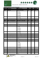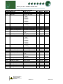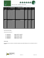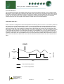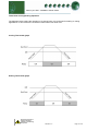
1
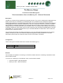
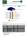
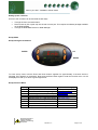
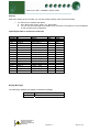
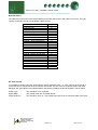
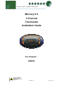
Mercury 6-5 Stat – Installation & User Guide
Mercury 6-5
5 Channel
Thermostat
Installation Guide
For Product: PR0091
Ensure that all power is
switched off before
installing or maintaining
this product
Revision 1.2
Page 1 of 21
Mercury 6-5 Stat – Installation & User Guide
Table of Contents:
THE MERCURY RANGE .................................................................................................................................... 3
Description ......................................................................................................................................................... 3
Configuration ..................................................................................................................................................... 3
Network............................................................................................................................................................... 3
Connections ....................................................................................................................................................... 4
Input/Output Allocation Tables ........................................................................................................................ 4
Setting up the controller ................................................................................................................................... 5
Set-up Mode..................................................................................................................................................... 5
Set-up through front buttons ............................................................................................................................ 5
Set-up Function Menu...................................................................................................................................... 5
Recommended set-up method ......................................................................................................................... 6
rtc. Real time clock (This will automatically synchronise on network systems)............................................... 6
type. view controller type ................................................................................................................................. 6
PArA. Set/view parameters (This can be achieved at the network front end) ................................................. 6
Parameter Tables:.............................................................................................................................................. 7
Parameter table for 5 Channel Thermostat ..................................................................................................... 7
Units and Probe Type........................................................................................................................................ 9
Probe Fault....................................................................................................................................................... 9
Network Configuration.................................................................................................................................... 10
IP Futura module............................................................................................................................................ 10
IP-L ............................................................................................................................................................. 10
IP-r.............................................................................................................................................................. 10
Over-ride Operation......................................................................................................................................... 11
Thermostat Over-ride: - .............................................................................................................................. 11
Normal Operation ............................................................................................................................................ 12
Frost Detect.................................................................................................................................................... 12
Invert .............................................................................................................................................................. 12
Network .......................................................................................................................................................... 12
Probe Offset ................................................................................................................................................... 12
Channel Off .................................................................................................................................................... 12
Channel Timer................................................................................................................................................ 12
Thermostat Cooling/Heating Operation ........................................................................................................ 13
Cooling Thermostat graph ............................................................................................................................. 13
Heating Thermostat graph ............................................................................................................................. 13
Viewing ............................................................................................................................................................. 14
Input/Output table for 5 Channel Thermostat ................................................................................................ 14
Display Messages............................................................................................................................................ 14
Network Alarms ............................................................................................................................................... 15
GP Timer Set-up............................................................................................................................................... 15
Specification .................................................................................................................................................... 16
General .......................................................................................................................................................... 16
Power requirements:...................................................................................................................................... 16
Relays ............................................................................................................................................................ 16
Warning:......................................................................................................................................................... 16
Inputs: ............................................................................................................................................................ 17
Installation:....................................................................................................................................................... 18
Fixing:............................................................................................................................................................. 18
Clearances: .................................................................................................................................................... 18
Wiring: .............................................................................................................................................................. 19
Over-ride input Resistors: .............................................................................................................................. 19
Fuse: ................................................................................................................................................................. 20
Cleaning: .......................................................................................................................................................... 20
Revision History .............................................................................................................................................. 21
Ensure that all power is
switched off before
installing or maintaining
this product
Revision 1.2
Page 2 of 21
Mercury 6-5 Stat – Installation & User Guide
The Mercury Range
From Resource Data Management
This documentation refers to the Mercury 6-5 - 5 Channel Thermostat
Description
The Mercury 5 Channel Thermostat has 5 thermostat functions. They can be configured for independent use,
where each function is controlled by an individual probe or the controller can be configured to operate
selected thermostats from one temperature probe. Each channel can be individually configured for heating or
cooling applications with a selection of parameters. There is a 7-day timer with two on and off’s. Included in
the controller is a frost detect parameter. This over-rides the timer function, when the timer is off, to begin
heating should the channel probe reach the frost detect value. The controller has the ability to use any of the
channels to operate as a timer. Each input can also accept over-ride commands as detailed later in the user
guide. Note:- the over-ride commands work only on channels selected as a thermostat, it has no effect if a
channel is set to operate as a timer.
The 5 Channel Thermostat can operate stand-alone or it can be networked through either an "IP" network
module or a Mercury IP Hub. The 5 Channel Thermostat supports PT1000 or NTC2000 or NTC2k25
temperature probes (note all 6 inputs are either PT1000 or NTC2000 or NTC2k25)
Configuration
There is one type of controller within the 5 Channel Thermostat (Type 1)
Display value
1
Type M
5 Channel Thermostat
Network
The controllers are capable of connecting to a TCP/IP local area network or controlling in standalone mode
with no network output.
To connect to a network you must add the correct communications module.
•
•
IP Futura module - (Part No PR0016)
Mercury IP Hub - (Part No PR0018)
Ensure that all power is
switched off before
installing or maintaining
this product
Revision 1.2
Page 3 of 21
Mercury 6-5 Stat – Installation & User Guide
Connections
All connections are made to the back of the controller. The diagram below shows the connection detail. Inputs
and outputs are assigned according to the chosen configuration. See Specification for further details on
connections.
!
Do not connect an earth.
Input/Output Allocation Tables
An over-ride can be achieved by switching in a fixed value resistor in parallel with the probe inputs as shown
in the table below.
5 Ch Thermostat
Description
Alarm Action
(Switched Resistor)*
Input 1
Input 2
Input 3
Input 4
Input 5
Relay 1
Relay 2
Relay 3
Relay 4
Relay 5
Probe 1 and Over-ride 1
Probe 2 and Over-ride 2
Probe 3 and Over-ride 3
Probe 4 and Over-ride 4
Probe 5 and Over-ride 5
Thermostat Channel 1
Thermostat Channel 2
Thermostat Channel 3
Thermostat Channel 4
Thermostat Channel 5
Yes
Yes
Yes
Yes
Yes
N/A
N/A
N/A
N/A
N/A
Over-ride signal 1
Over-ride signal 2
Over-ride signal 3
Over-ride signal 4
Over-ride signal 5
* For PT1000 probes use 820 Ohm
For NTC2000 and NTC2k25 probes use 590 Ohm
Ensure that all power is
switched off before
installing or maintaining
this product
Revision 1.2
Page 4 of 21
Mercury 6-5 Stat – Installation & User Guide
Setting up the controller
Access to the controller can be achieved several ways
•
•
•
Through the front mounted buttons
Direct access by PC or palm top into the rear comms port. This requires a software package available
on the RDM website
Through the RDM Data Director or Data Manager.
Set-up Mode
Set-up through front buttons
ENTER
UP
DOWN
To enter set-up mode, hold the Enter and Down buttons together for approximately 3 seconds until the
message “Ent” appears on the display. Now press the Enter button again to enter the function menu. IO will
be displayed. Scroll up or down to go through the list.
Set-up Function Menu
Display
IO
PArA
Unit
TyPE
rtc
nEt
SoFt
OFSt
ESC
Option
View Input/Output States
Set/view Parameters
Set Probe type and units ( oC or oF)
Set/View Controller Type
Set/view Clock (rtc = Real Time Clock)
Set/view network configuration
View software version
Probe offset
Escape back to normal operation
Ensure that all power is
switched off before
installing or maintaining
this product
Revision 1.2
Explained in Paragraph
View Input/Output States
Set/view parameters
Set/view units
Set/view product type
Real Time Clock
Network Configuration
Probe Offset
Page 5 of 21
Mercury 6-5 Stat – Installation & User Guide
Recommended set-up method
If you are not connecting to a network and want to set up the controller through the buttons we recommend
you use the following order from the function menu.
rtc. Real time clock (This will automatically synchronise on network systems)
a.
b.
c.
d.
e.
f.
g.
h.
i.
j.
Use the up or down buttons to scroll through the display until the display reads “rtc”
Press enter. The display will show “t-1”. press enter again
Scroll hours up or down (0 – 23) press enter
Use up button to select “t-2”, press enter
Scroll minutes up or down (0 – 59) press enter
Repeat for t-3
(seconds 0 – 59)
Repeat for t -4
(Days up to 31)
Repeat for t -5
(months up to 12)
Repeat for t -6
(Year up to 99)
Use up button to display “ESC”, press enter to display “rtc”
Time clock is now set
type. view controller type
The controller Type is preset at the factory and cannot be changed.
a.
b.
c.
d.
e.
From the function menu scroll to select type, press enter
View the type number 1
Press enter.
Scroll to select “ESC”
Press enter
PArA. Set/view parameters (This can be achieved at the network front end)
a. From the function menu scroll to select PArA
b. Pressing Enter while PArA is displayed will enter the parameter menu. The first parameter option
will be displayed as P-01. Pressing the Up or Down button will present the other parameter
options P-02, P-03 etc. See the parameter list below to find what parameter number corresponds
to which actual parameter. Pressing the Enter button will show the current value of the selected
parameter. Press Up or Down to modify the value and press Enter again to save the value. The
parameter list number will be displayed again. Two other options are present in the parameter
menu – dFLt and ESC. Selecting ESC will exit setup mode. Selecting dFLt will reset all
parameters back to the default values for the current type of controller.
Ensure that all power is
switched off before
installing or maintaining
this product
Revision 1.2
Page 6 of 21
Mercury 6-5 Stat – Installation & User Guide
Parameter Tables:
Parameter table for 5 Channel Thermostat
Number Parameter
Range oC ( oF )
P-01
Stat1 Temp Cut-In
-49 to 30oC (-56.2 to 86)
P-02
Stat1 Diff
0 to 10oC (32 to 50)
P-03
Stat1 Select
0 = Off
1 = Timer
2 = Probe 1
3 = Probe 2
4 = Probe 3
5 = Probe 4
6 = Probe 5
P-04
Stat1 Type
0 = Cooling
1 = Heating
P-06
Stat1 Frost Detect
-42 to 128oC (-43 to 262)
P-07
Stat1 High Temp Alarm
-42 to 128oC (-43 to 262)
P-08
Stat1 Low Temp Alarm
-42 to 128oC (-43 to 262)
P-09
Stat1 Alm Delay
00:00 to 99:00
P-10
Stat1 Rly Inv
0 = Off
1 = On
P-11
Stat2 Temp Cut-In
-49 to 30oC (-56.2 to 86)
P-12
Stat2 Diff
0 to 10oC (32 to 50)
P-13
Stat2 Select
0 = Off
1 = Timer
2 = Probe 1
3 = Probe 2
4 = Probe 3
5 = Probe 4
6 = Probe 5
P-14
Stat2 Type
0 = Cooling
1 = Heating
P-16
Stat2 Frost Detect
-42 to 128oC (-43 to 262)
P-17
Stat2 High Temp Alarm
-42 to 128oC (-43 to 262)
P-18
Stat2 Low Temp Alarm
-42 to 128oC (-43 to 262)
P-19
Stat2 Alm Delay
00:00 to 99:00
P-20
Stat2 Rly Inv
0 = Off
1 = On
P-21
Stat3 Temp Cut-In
-49 to 30oC (-56.2 to 86)
P-22
Stat3 Diff
0 to 10oC (32 to 50)
P-23
Stat3 Select
0 = Off
1 = Timer
2 = Probe 1
3 = Probe 2
4 = Probe 3
5 = Probe 4
6 = Probe 5
P-24
Stat3 Type
0 = Cooling
1 = Heating
P-26
Stat3 Frost Detect
-42 to 128oC (-43 to 262)
P-27
Stat3 High Temp Alarm
-42 to 128oC (-43 to 262)
P-28
Stat3 Low Temp Alarm
-42 to 128oC (-43 to 262)
P-29
Stat3 Alm Delay
00:00 to 99:00
P-30
Stat3 Rly Inv
0 = Off
1 = On
Ensure that all power is
switched off before
installing or maintaining
this product
Revision 1.2
Step
0.1
0.1
1
Units
Deg
Deg
1
Default
15.0
5.0
2
1
0.1
0.1
0.1
01:00
1
Deg
Deg
Deg
mm:ss
0.0
25.0
0.0
20:00
0
0.1
0.1
1
Deg
Deg
15.0
5.0
3
1
1
0.1
0.1
0.1
01:00
1
Deg
Deg
Deg
mm:ss
0.0
25.0
0.0
20:00
0
0.1
0.1
1
Deg
Deg
15.0
5.0
4
1
0.1
0.1
0.1
01:00
1
1
Deg
Deg
Deg
mm:ss
0.0
25.0
0.0
20:00
0
Page 7 of 21
Mercury 6-5 Stat – Installation & User Guide
Parameter table for 5 Channel Thermostat Continued.......
Number Parameter
Range oC ( oF )
P-31
Stat4 Temp Cut-In
-49 to 30oC (-56.2 to 86)
P-32
Stat4 Diff
0 to 10oC (32 to 50)
P-33
Stat4 Select
0 = Off
1 = Timer
2 = Probe 1
3 = Probe 2
4 = Probe 3
5 = Probe 4
6 = Probe 5
P-34
Stat4 Type
0 = Cooling
1 = Heating
P-36
Stat4 Frost Detect
-42 to 128oC (-43 to 262)
P-37
Stat4 High Temp Alarm
-42 to 128oC (-43 to 262)
P-38
Stat4 Low Temp Alarm
-42 to 128oC (-43 to 262)
P-39
Stat4 Alm Delay
00:00 to 99:00
P-40
Stat4 Rly Inv
0 = Off
1 = On
P-41
Stat5 Temp Cut-In
-49 to 30oC (-56.2 to 86)
P-42
Stat5 Diff
0 to 10oC (32 to 50)
P-43
Stat5 Select
0 = Off
1 = Timer
2 = Probe 1
3 = Probe 2
4 = Probe 3
5 = Probe 4
6 = Probe 5
P-44
Stat5 Type
0 = Cooling
1 = Heating
P-46
Stat5 Frost Detect
-42 to 128oC (-43 to 262)
P-47
Stat5 High Temp Alarm
-42 to 128oC (-43 to 262)
P-48
Stat5 Low Temp Alarm
-42 to 128oC (-43 to 262)
P-49
Stat5 Alm Delay
00:00 to 99:00
P-50
Stat5 Rly Inv
0 = Off
1 = On
P-70
Timer Mode
0 = Local
1 = Remote
P71
Sunday On Time 1
00:00 to 23:59
P72
Sunday Off Time 1
00:00 to 23:59
P73
Sunday On Time 2
00:00 to 23:59
P74
Sunday Off Time 2
00:00 to 23:59
P75
Monday On Time 1
00:00 to 23:59
P76
Monday Off Time 1
00:00 to 23:59
P77
Monday On Time 2
00:00 to 23:59
P78
Monday Off Time 2
00:00 to 23:59
Ensure that all power is
switched off before
installing or maintaining
this product
Revision 1.2
Step
0.1
0.1
1
Units
Deg
Deg
1
Default
15.0
5.0
5
1
0.1
0.1
0.1
01:00
1
Deg
Deg
Deg
mm:ss
0.0
25.0
0.0
20:00
0
0.1
0.1
1
Deg
Deg
15.0
5.0
1
1
0.1
0.1
0.1
01:00
1
1
Deg
Deg
Deg
mm:ss
1
00:01
00:01
00:01
00:01
00:01
00:01
00:01
00:01
0.0
25.0
0.0
20:00
0
0
hh:mm
hh:mm
hh:mm
hh:mm
hh:mm
hh:mm
hh:mm
hh:mm
08:00
20:00
08:00
20:00
08:00
20:00
08:00
20:00
Page 8 of 21
Mercury 6-5 Stat – Installation & User Guide
Parameter table for 5 Channel Thermostat Continued.......
Number Parameter
Range
P79
Tuesday On Time 1
00:00 to 23:59
P80
Tuesday Off Time 1
00:00 to 23:59
P81
Tuesday On Time 2
00:00 to 23:59
P82
Tuesday Off Time 2
00:00 to 23:59
P83
Wednesday On Time 1 00:00 to 23:59
P84
Wednesday Off Time 1 00:00 to 23:59
P85
Wednesday On Time 2 00:00 to 23:59
P86
Wednesday Off Time 2 00:00 to 23:59
P87
Thursday On Time 1
00:00 to 23:59
P88
Thursday Off Time 1
00:00 to 23:59
P89
Thursday On Time 2
00:00 to 23:59
P90
Thursday Off Time 2
00:00 to 23:59
P91
Friday On Time 1
00:00 to 23:59
P92
Friday Off Time 1
00:00 to 23:59
P93
Friday On Time 2
00:00 to 23:59
P94
Friday Off Time 2
00:00 to 23:59
P95
Saturday On Time 1
00:00 to 23:59
P96
Saturday Off Time 1
00:00 to 23:59
P97
Saturday On Time 2
00:00 to 23:59
P98
Saturday Off Time 2
00:00 to 23:59
dFLt
Factory Defaults
Step
00:01
00:01
00:01
00:01
00:01
00:01
00:01
00:01
00:01
00:01
00:01
00:01
00:01
00:01
00:01
00:01
00:01
00:01
00:01
00:01
Units
hh:mm
hh:mm
hh:mm
hh:mm
hh:mm
hh:mm
hh:mm
hh:mm
hh:mm
hh:mm
hh:mm
hh:mm
hh:mm
hh:mm
hh:mm
hh:mm
hh:mm
hh:mm
hh:mm
hh:mm
Default
08:00
20:00
08:00
20:00
08:00
20:00
08:00
20:00
08:00
20:00
08:00
20:00
08:00
20:00
08:00
20:00
08:00
20:00
08:00
20:00
Units and Probe Type
Change the probe type to: -
0=
1=
2=
3=
4=
5=
PTC1000 oC
PTC1000 oF
NTC2000 oC
NTC2000 oF
NTC2k25 oC
NTC2k25 oF
Range -42 oC to +128 oC
Range -43 oF to +262 oF
Range -37 oC to +54 oC
Range -34oF to +129 oF
Range -37 oC to +54 oC
Range -34oF to +129 oF
Probe Fault
If a probe fault occurs then the controller will pulse its associated relay(s) on for 5 minutes then off for 5
minutes.
Ensure that all power is
switched off before
installing or maintaining
this product
Revision 1.2
Page 9 of 21
Mercury 6-5 Stat – Installation & User Guide
Network Configuration
The final section to set-up is the network address. In all instances, this must be done before the controller is
plugged into the site network. The controllers have an auto-initialise function, which will automatically log the
device onto the site network. If the wrong address has been entered onto the network, you will have to reset
the controller address by setting the address to 00-0, and then re-enter the correct address. (You may have to
deregister the wrong address from the home system as well).
To set the controller onto a network you must first connect the controller to a communications module. This is
either a: • IP Futura or
• Mercury Hub
IP Futura module
In an IP system there are two options
• IP-L
• IP-r
IP-L allows you to fix an IP address into the controller, which you would use when you are connecting the
controllers onto a customer’s local area network. This would allow the customer to view each controller using
Internet Explorer
IP-r allows you to give each controller on the system a unique number. This number is then allocated a
dynamic IP address by the system DHCP server (such as the RDM Data Director)
IP-L
To configure the communication module for IP-L, set all three rotary switches to zero. The module should
then be connected to the controller.
1. nEt. From the function menu you can now select nEt
• Press enter and the display will show “IP-L”, press enter
• You can now set the address using the table below
Display
IP-1
IP-2
IP-3
IP-4
nL
gt-1
gt-2
gt-3
gt-4
ESC
Option
IP Address byte 1
IP Address byte 2
IP Address byte 3
IP Address byte 4
Network Mask Length
Gateway Address byte 1
Gateway Address byte 2
Gateway Address byte 3
Gateway Address byte 4
Exit network menu. N.B. this option must be selected
to save any changes made in this menu
IP-r
To configure the communication module for IP-r, set the three rotary switches to give each controller a unique
identifier. The module should then be connected to the controller and the network.
The green network LED on the controller will flash until it has been logged on to the network. The Green
network LED will remain permanently on while it is on-line.
Please refer to the Mercury Hub user guide, which can be obtained from the RDM website, for information
regarding connecting a controller to a network.
Ensure that all power is
switched off before
installing or maintaining
this product
Revision 1.2
Page 10 of 21
Mercury 6-5 Stat – Installation & User Guide
Over-ride Operation
The 5 Channel Thermostat can operate either from its internal channel time settings or from a network Data
Manager GP Timer channel (P70 sets the mode either local or remote). If the 5 Channel Thermostat is set up
to use the remote timing channels it reverts to local mode if network communications are lost for more than 5
minutes. An over-ride occurs when a resistor is switched in across the input which has to be overridden,
however when the over-ride signal is removed the channel returns too normal operation.
Thermostat Over-ride: -
When a channel is configured for thermostat operation the following will occur when an over-ride is present on
the channel input. In the example below channel 1 is set as a thermostat in a heating application, the relay
inverse feature is disabled, the controller timer is set to local operation and is off. When the timer is in the off
period the channel will not be enabled for heating and the thermostat relay remains off, providing the probe
temperature is not below the frost detect set point. As shown in the diagram an over-ride is applied to channel
1, this will enable the channel. The thermostat relay does not immediately turn on, it only does so when the
temperature drops below the cut-in set point. The controller will continue normal temperature control until the
over-ride is removed or the next scheduled off occurs in the local timer schedule. When the timer is in the on
period, the over-ride has no effect. Note:- An over-ride should be removed as soon as it is not required on an
input.
Over-ride
Activated
Cut-in Set
Point
On
Off
Frost
Detect
Relay State
Temperature
Diff
Time
Thermostat Relay Status
Ch 1 Probe Temperature
Ensure that all power is
switched off before
installing or maintaining
this product
Revision 1.2
Page 11 of 21
Mercury 6-5 Stat – Installation & User Guide
Normal Operation
During normal operation, the controller will display "on". If the 5 Channel Thermostat is on a network and online, the green network LED will be on. If any alarms are generated the red LED will light. The yellow LED has
no function and will not light.
Frost Detect
The frost detect parameter is used to provide heating in an instance where the timer status is off. Each
thermostat channel has its own frost detect value that can be configured. Once the temperature drops below
the frost detect value the controller channel will heat to the frost detect value plus the channels diff parameter.
For example the 5 Channel Thermostat is used to heat a room, the channel configured has a diff of 5oC, a
frost detect value of 0oC and the timer is off. The channel will switch its associated relay on when the
temperature drops below 0oC. The room will begin to heat and the relay is on, it will stay on until the
temperature rises above 5oC. At this point the relay will be turned off. The relay will be turned on again if the
room temperature drops below 0oC.
Invert
The 5 Channel Thermostat has a channel setting to invert the output, if this option is used, the output is off
when the timer is on and the output is on when the timer is off.
Network
The Network green LED flashes if the controller goes off-line.
Probe Offset
Each probe can be offset by up to ±10 oC to compensate for long cable runs.
Channel Off
It is possible to turn channels off if they are not in use.
Channel Timer
It is possible to use each channel as a timer. The channel will follow the controller’s internal timer schedule or
a remote GP timer for on and off times.
Ensure that all power is
switched off before
installing or maintaining
this product
Revision 1.2
Page 12 of 21
Mercury 6-5 Stat – Installation & User Guide
Thermostat Cooling/Heating Operation
The diagrams below outline the operation of a channel when it is configured for heating or cooling
applications. In this instance the 5 Channel Thermostat’s local timer is on.
Cooling Thermostat graph
Heating Thermostat graph
Ensure that all power is
switched off before
installing or maintaining
this product
Revision 1.2
Page 13 of 21
Mercury 6-5 Stat – Installation & User Guide
Viewing
Apart from setting up the controller, you can also view the status of the inputs and outputs.
1. IO. View Inputs / Outputs and States
a. From the function menu, select “IO”, press enter
b. You can now scroll through the IO tables as set out below. The tables you view will depend
on the controller type configuration.
Input/Output table for 5 Channel Thermostat
Number
I-01
I-02
I-03
I-04
I-05
I-06
I-07
I-08
I-09
I-10
O-01
O-02
O-03
O-04
O-05
O-06
IO
Probe 1
Probe 2
Probe 3
Probe 4
Probe 5
Over-ride 1
Over-ride 2
Over-ride 3
Over-ride 4
Over-ride 5
Relay 1
Relay 2
Relay 3
Relay 4
Relay 5
Timer
Range
-42 to 128 oC
-42 to 128 oC
-42 to 128 oC
-42 to 128 oC
-42 to 128 oC
0 (Off), 1 (On)
0 (Off), 1 (On)
0 (Off), 1 (On)
0 (Off), 1 (On)
0 (Off), 1 (On)
0 (Off), 1 (On)
0 (Off), 1 (On)
0 (Off), 1 (On)
0 (Off), 1 (On)
0 (Off), 1 (On)
0 (Off), 1 (On)
Step
0.1
0.1
0.1
0.1
0.1
Units
Deg
Deg
Deg
Deg
Deg
Display Messages
The following messages can appear on the Mercury display.
Display
on
Ensure that all power is
switched off before
installing or maintaining
this product
System status
Controller On
Revision 1.2
Page 14 of 21
Mercury 6-5 Stat – Installation & User Guide
Network Alarms
The table below shows the text and associated type number that is sent to the system "front end". The type
number is normally used to provide different alarm actions.
Alarm text
Probe 1 Faulty
Probe 2 Faulty
Probe 3 Faulty
Probe 4 Faulty
Probe 5 Faulty
Type
6
6
6
6
6
Channel 1 Over Temperature
Channel 2 Over Temperature
Channel 3 Over Temperature
Channel 4 Over Temperature
Channel 5 Over Temperature
4
4
4
4
4
Channel 1 Under Temperature
Channel 2 Under Temperature
Channel 3 Under Temperature
Channel 4 Under Temperature
Channel 5 Under Temperature
5
5
5
5
5
Channel 1 Over-ride
Channel 2 Over-ride
Channel 3 Over-ride
Channel 4 Over-ride
Channel 5 Over-ride
16
16
16
16
16
GP Timer Set-up
It is possible to set the 5 Channel Thermostat for remote operation (P70 = 1). A GP Timer must be set up to
control the timer on/off periods of the 5 Channel Thermostat. For GP Timer set up please refer to the Data
Manager user guide found on the RDM website. The following settings should be followed in the GP setup.
Output Type
–
Output Mask
–
Output Channel –
This should be set to “General”.
This should match the “Controller Name”.
This should be set to “5”. This will allow the GP Timer to control the state of the timer.
Ensure that all power is
switched off before
installing or maintaining
this product
Revision 1.2
Page 15 of 21
Mercury 6-5 Stat – Installation & User Guide
Specification
General
Power requirements:
Supply Voltage Range:
Supply Frequency:
Maximum supply current:
Typical supply current:
Operating temperature range:
Operating Humidity:
Storage temperature range:
Environmental:
Size:
Weight:
Safety:
EMC:
Ventilation:
Class 2 Insulation:
100 - 240 Vac ±10%
50 - 60 Hz ±10%
<1 Amp (With no relay loads)
<0.5 Amp
+50C to +500C
80% maximum
-200C to +650C
Indoor use at altitudes up to 2000m, Pollution Degree 1,
Installation Category II.
Voltage fluctuations not to exceed ±10% of nominal voltage
110mm (W) x 60mm (H) x 100mm (D)
150 Grams
EN61010
EN61326; 1997 +Amdt. A1; 1998
There is no requirement for forced cooling ventilation
No protective Earth is required and none should be fitted.
The host equipment must provide a suitable external over-current protection device such as: Fuse:
6.3A 240 Vac Antisurge (T) HRC conforming to IEC 60127
Or MCB:
8A, 240 VAC Type C conforming to BS EN 60898
The host equipment must provide adequate protection against contact to hazardous live parts.
Relays
Max current relay 1:
Max Voltage relay 1:
Exclusive common
6A (non inductive)
260Vac (external supply)
Max current relay 2:
Max Voltage relay 2:
Shared common with relay 3
4A (non inductive)
260Vac (external supply)
Max current relay 3:
Max Voltage relay 3:
Shared common with relay 2
4A (non inductive)
260Vac (external supply)
Max current relay 4:
Max Voltage relay 4:
Common connected to Input "live"
3A (non inductive)
260Vac (Internal supply)
Max current relay 5:
Max Voltage relay 5:
Common connected to Input "live"
3A (non inductive)
260Vac (Internal supply)
Relays 2 and 3 share a common
supply line and the loads can
have a combined total of 8A.
Relay 2 or 3 can switch a maximum
of 6A provided the other is at 2A or.
lower.
For compliance with the LVD, relays 2 and 3 common must be at the same potential as the supply voltage.
!
Warning:
Relays 4 and 5 outputs have hazardous voltages (Supply input voltage potential).
Ensure that all power is
switched off before
installing or maintaining
this product
Revision 1.2
Page 16 of 21
Mercury 6-5 Stat – Installation & User Guide
Inputs:
Input resistance:
Input type
3.01K Ohms (for PTC or NTC type probes)
PT1000
NTC2000
NTC2k25
Comms:
RS232 with flow control
Ensure that all power is
switched off before
installing or maintaining
this product
Revision 1.2
Page 17 of 21
Mercury 6-5 Stat – Installation & User Guide
Installation:
Panel Cut-out:
72mm
17mm
34mm
93mm
2 holes: 3.5mm dia.
Fixing:
The controller can be fixed either by 2 X M3 screws from the rear or by the plastic retaining device (PR0329),
obtainable from RDM.
Clearances:
The controller must have 5mm clearance above the top and below bottom, and 25mm clearance from the
sides. Clearance at the rear is dependant on the wiring.
There is no requirement for forced cooling ventilation
Ensure that all power is
switched off before
installing or maintaining
this product
Revision 1.2
Page 18 of 21
Mercury 6-5 Stat – Installation & User Guide
Wiring:
!
Relay 4 and 5 N/O are fed from the supply input
Note:
Suitable mechanical restraints on the wiring to the controller may be required; dependant on cable types, to
prevent undue stress or distortion on the controller connectors.
Over-ride input Resistors:
Supply Neutral
Not Used
Supply Live, Relay 4&5 Common
Example of 820-Ohm resistor fitted on Input 2
Relay 5 N/O
Relay 4 N/O
Relay 2&3 Common
Relay 3 N/O
Relay 2 N/O
Relay 1 Common
Relay 1 N/O
Connect to remote switch
Ensure that all power is
switched off before
installing or maintaining
this product
Revision 1.2
Page 19 of 21
Mercury 6-5 Stat – Installation & User Guide
Fuse:
The host equipment must provide a suitable external over-current protection device such as: Fuse:
Or MCB:
6.3A, 240 Vac Antisurge (T) HRC conforming to IEC 60127 (Relay 4 & 5 fully loaded)
8A, 240 Vac Type C conforming to BS EN 60898 (Relay 4 & 5 fully loaded)
Cleaning:
Do not wet the controller when cleaning. Clean the front by wiping with slightly damped lint free cloth.
Please note: The specifications of the product detailed on this set up guide may change without
notice. RDM Ltd shall not be liable for errors or for incidental or consequential damages, directly or
indirectly, in connection with the furnishing, performance or misuse of this product or document.
Ensure that all power is
switched off before
installing or maintaining
this product
Revision 1.2
Page 20 of 21
Mercury 6-5 Stat – Installation & User Guide
Revision History
Revision
Date
Changes
1.0
1.1
1.2
27/10/2006
01/03/2007
05/03/2007
First Issue
General Tidy Up
Removal of over-ride description (for when a channel is configured as a
timer).
Ensure that all power is
switched off before
installing or maintaining
this product
Revision 1.2
Page 21 of 21