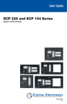
1
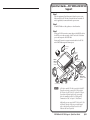
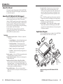
User’s Manual RCP 2000 with ISS 506 Support Extron USA - West Headquarters +800.633.9876 Inside USA / Canada Only +1.714.491.1500 +1.714.491.1517 FAX Extron USA - East Extron Europe Extron Asia Extron Japan Extron China Extron Dubai +800.633.9876 +800.3987.6673 +800.7339.8766 +81.3.3511.7655 +81.3.3511.7656 FAX +400.883.1568 +971.4.2991800 +971.4.2991880 FAX +1.919.863.1794 +1.919.863.1797 FAX +31.33.453.4040 +31.33.453.4050 FAX +65.6383.4400 +65.6383.4664 FAX Inside USA / Canada Only Inside Europe Only Inside Asia Only © 2008 Extron Electronics. All rights reserved. Inside China Only +86.21.3760.1568 +86.21.3760.1566 FAX Remote Control Panel 68-1609-01 Rev. A 08 08 Precautions Safety Instructions • English This symbol is intended to alert the user of important operating and maintenance (servicing) instructions in the literature provided with the equipment. This symbol is intended to alert the user of the presence of uninsulated dangerous voltage within the product’s enclosure that may present a risk of electric shock. Caution Read Instructions • Read and understand all safety and operating instructions before using the equipment. Retain Instructions • The safety instructions should be kept for future reference. Follow Warnings • Follow all warnings and instructions marked on the equipment or in the user information. Avoid Attachments • Do not use tools or attachments that are not recommended by the equipment manufacturer because they may be hazardous. Consignes de Sécurité • Français Ce symbole sert à avertir l’utilisateur que la documentation fournie avec le matériel contient des instructions importantes concernant l’exploitation et la maintenance (réparation). Ce symbole sert à avertir l’utilisateur de la présence dans le boîtier de l’appareil de tensions dangereuses non isolées posant des risques d’électrocution. Attention Lire les instructions• Prendre connaissance de toutes les consignes de sécurité et d’exploitation avant d’utiliser le matériel. Conserver les instructions• Ranger les consignes de sécurité afin de pouvoir les consulter à l’avenir. Respecter les avertissements • Observer tous les avertissements et consignes marqués sur le matériel ou présentés dans la documentation utilisateur. Eviter les pièces de fixation • Ne pas utiliser de pièces de fixation ni d’outils non recommandés par le fabricant du matériel car cela risquerait de poser certains dangers. Sicherheitsanleitungen • Deutsch Dieses Symbol soll dem Benutzer in der im Lieferumfang enthaltenen Dokumentation besonders wichtige Hinweise zur Bedienung und Wartung (Instandhaltung) geben. Dieses Symbol soll den Benutzer darauf aufmerksam machen, daß im Inneren des Gehäuses dieses Produktes gefährliche Spannungen, die nicht isoliert sind und die einen elektrischen Schock verursachen können, herrschen. Achtung Lesen der Anleitungen • Bevor Sie das Gerät zum ersten Mal verwenden, sollten Sie alle Sicherheits-und Bedienungsanleitungen genau durchlesen und verstehen. Aufbewahren der Anleitungen • Die Hinweise zur elektrischen Sicherheit des Produktes sollten Sie aufbewahren, damit Sie im Bedarfsfall darauf zurückgreifen können. Befolgen der Warnhinweise • Befolgen Sie alle Warnhinweise und Anleitungen auf dem Gerät oder in der Benutzerdokumentation. Keine Zusatzgeräte • Verwenden Sie keine Werkzeuge oder Zusatzgeräte, die nicht ausdrücklich vom Hersteller empfohlen wurden, da diese eine Gefahrenquelle darstellen können. Instrucciones de seguridad • Español Este símbolo se utiliza para advertir al usuario sobre instrucciones importantes de operación y mantenimiento (o cambio de partes) que se desean destacar en el contenido de la documentación suministrada con los equipos. Este símbolo se utiliza para advertir al usuario sobre la presencia de elementos con voltaje peligroso sin protección aislante, que puedan encontrarse dentro de la caja o alojamiento del producto, y que puedan representar riesgo de electrocución. Precaucion Leer las instrucciones • Leer y analizar todas las instrucciones de operación y seguridad, antes de usar el equipo. Conservar las instrucciones • Conservar las instrucciones de seguridad para futura consulta. Obedecer las advertencias • Todas las advertencias e instrucciones marcadas en el equipo o en la documentación del usuario, deben ser obedecidas. Evitar el uso de accesorios • No usar herramientas o accesorios que no sean especificamente recomendados por el fabricante, ya que podrian implicar riesgos. Extron’s Warranty Warning Power sources • This equipment should be operated only from the power source indicated on the product. This equipment is intended to be used with a main power system with a grounded (neutral) conductor. The third (grounding) pin is a safety feature, do not attempt to bypass or disable it. Power disconnection • To remove power from the equipment safely, remove all power cords from the rear of the equipment, or the desktop power module (if detachable), or from the power source receptacle (wall plug). Power cord protection • Power cords should be routed so that they are not likely to be stepped on or pinched by items placed upon or against them. Servicing • Refer all servicing to qualified service personnel. There are no userserviceable parts inside. To prevent the risk of shock, do not attempt to service this equipment yourself because opening or removing covers may expose you to dangerous voltage or other hazards. Slots and openings • If the equipment has slots or holes in the enclosure, these are provided to prevent overheating of sensitive components inside. These openings must never be blocked by other objects. Lithium battery • There is a danger of explosion if battery is incorrectly replaced. Replace it only with the same or equivalent type recommended by the manufacturer. Dispose of used batteries according to the manufacturer’s instructions. Avertissement Alimentations• Ne faire fonctionner ce matériel qu’avec la source d’alimentation indiquée sur l’appareil. Ce matériel doit être utilisé avec une alimentation principale comportant un fil de terre (neutre). Le troisième contact (de mise à la terre) constitue un dispositif de sécurité : n’essayez pas de la contourner ni de la désactiver. Déconnexion de l’alimentation• Pour mettre le matériel hors tension sans danger, déconnectez tous les cordons d’alimentation de l’arrière de l’appareil ou du module d’alimentation de bureau (s’il est amovible) ou encore de la prise secteur. Protection du cordon d’alimentation • Acheminer les cordons d’alimentation de manière à ce que personne ne risque de marcher dessus et à ce qu’ils ne soient pas écrasés ou pincés par des objets. Réparation-maintenance • Faire exécuter toutes les interventions de réparationmaintenance par un technicien qualifié. Aucun des éléments internes ne peut être réparé par l’utilisateur. Afin d’éviter tout danger d’électrocution, l’utilisateur ne doit pas essayer de procéder lui-même à ces opérations car l’ouverture ou le retrait des couvercles risquent de l’exposer à de hautes tensions et autres dangers. Fentes et orifices • Si le boîtier de l’appareil comporte des fentes ou des orifices, ceux-ci servent à empêcher les composants internes sensibles de surchauffer. Ces ouvertures ne doivent jamais être bloquées par des objets. Lithium Batterie • Il a danger d’explosion s’ll y a remplacment incorrect de la batterie. Remplacer uniquement avec une batterie du meme type ou d’un ype equivalent recommande par le constructeur. Mettre au reut les batteries usagees conformement aux instructions du fabricant. Vorsicht Stromquellen • Dieses Gerät sollte nur über die auf dem Produkt angegebene Stromquelle betrieben werden. Dieses Gerät wurde für eine Verwendung mit einer Hauptstromleitung mit einem geerdeten (neutralen) Leiter konzipiert. Der dritte Kontakt ist für einen Erdanschluß, und stellt eine Sicherheitsfunktion dar. Diese sollte nicht umgangen oder außer Betrieb gesetzt werden. Stromunterbrechung • Um das Gerät auf sichere Weise vom Netz zu trennen, sollten Sie alle Netzkabel aus der Rückseite des Gerätes, aus der externen Stomversorgung (falls dies möglich ist) oder aus der Wandsteckdose ziehen. Schutz des Netzkabels • Netzkabel sollten stets so verlegt werden, daß sie nicht im Weg liegen und niemand darauf treten kann oder Objekte darauf- oder unmittelbar dagegengestellt werden können. Wartung • Alle Wartungsmaßnahmen sollten nur von qualifiziertem Servicepersonal durchgeführt werden. Die internen Komponenten des Gerätes sind wartungsfrei. Zur Vermeidung eines elektrischen Schocks versuchen Sie in keinem Fall, dieses Gerät selbst öffnen, da beim Entfernen der Abdeckungen die Gefahr eines elektrischen Schlags und/oder andere Gefahren bestehen. Schlitze und Öffnungen • Wenn das Gerät Schlitze oder Löcher im Gehäuse aufweist, dienen diese zur Vermeidung einer Überhitzung der empfindlichen Teile im Inneren. Diese Öffnungen dürfen niemals von anderen Objekten blockiert werden. Litium-Batterie • Explosionsgefahr, falls die Batterie nicht richtig ersetzt wird. Ersetzen Sie verbrauchte Batterien nur durch den gleichen oder einen vergleichbaren Batterietyp, der auch vom Hersteller empfohlen wird. Entsorgen Sie verbrauchte Batterien bitte gemäß den Herstelleranweisungen. Advertencia Alimentación eléctrica • Este equipo debe conectarse únicamente a la fuente/tipo de alimentación eléctrica indicada en el mismo. La alimentación eléctrica de este equipo debe provenir de un sistema de distribución general con conductor neutro a tierra. La tercera pata (puesta a tierra) es una medida de seguridad, no puentearia ni eliminaria. Desconexión de alimentación eléctrica • Para desconectar con seguridad la acometida de alimentación eléctrica al equipo, desenchufar todos los cables de alimentación en el panel trasero del equipo, o desenchufar el módulo de alimentación (si fuera independiente), o desenchufar el cable del receptáculo de la pared. Protección del cables de alimentación • Los cables de alimentación eléctrica se deben instalar en lugares donde no sean pisados ni apretados por objetos que se puedan apoyar sobre ellos. Reparaciones/mantenimiento • Solicitar siempre los servicios técnicos de personal calificado. En el interior no hay partes a las que el usuario deba acceder. Para evitar riesgo de electrocución, no intentar personalmente la reparación/mantenimiento de este equipo, ya que al abrir o extraer las tapas puede quedar expuesto a voltajes peligrosos u otros riesgos. Ranuras y aberturas • Si el equipo posee ranuras o orificios en su caja/alojamiento, es para evitar el sobrecalientamiento de componentes internos sensibles. Estas aberturas nunca se deben obstruir con otros objetos. Batería de litio • Existe riesgo de explosión si esta batería se coloca en la posición incorrecta. Cambiar esta batería únicamente con el mismo tipo (o su equivalente) recomendado por el fabricante. Desachar las baterías usadas siguiendo las instrucciones del fabricante. Extron Electronics warrants this product against defects in materials and workmanship for a period of three years from the date of purchase. In the event of malfunction during the warranty period attributable directly to faulty workmanship and/or materials, Extron Electronics will, at its option, repair or replace said products or components, to whatever extent it shall deem necessary to restore said product to proper operating condition, provided that it is returned within the warranty period, with proof of purchase and description of malfunction to: USA, Canada, South America, and Central America: Extron Electronics 1001 East Ball Road Anaheim, CA 92805, USA Asia: Extron Electronics, Asia 135 Joo Seng Road, #04-01 PM Industrial Bldg. Singapore 368363 Europe, Africa, and the Middle East: Extron Electronics, Europe Beeldschermweg 6C 3821 AH Amersfoort The Netherlands Japan: Extron Electronics, Japan Kyodo Building 16 Ichibancho Chiyoda-ku, Tokyo 102-0082 Japan This Limited Warranty does not apply if the fault has been caused by misuse, improper handling care, electrical or mechanical abuse, abnormal operating conditions or nonExtron authorized modification to the product. If it has been determined that the product is defective, please call Extron and ask for an Applications Engineer at (714) 491-1500 (USA), 31.33.453.4040 (Europe), 65.6383.4400 (Asia), or 81.3.3511.7655 (Japan) to receive an RA# (Return Authorization number). This will begin the repair process as quickly as possible. Units must be returned insured, with shipping charges prepaid. If not insured, you assume the risk of loss or damage during shipment. Returned units must include the serial number and a description of the problem, as well as the name of the person to contact in case there are any questions. Extron Electronics makes no further warranties either expressed or implied with respect to the product and its quality, performance, merchantability, or fitness for any particular use. In no event will Extron Electronics be liable for direct, indirect, or consequential damages resulting from any defect in this product even if Extron Electronics has been advised of such damage. Please note that laws vary from state to state and country to country, and that some provisions of this warranty may not apply to you. 安全须知 • 中文 警告 这个符号提示用户该设备用户手册中 有重要的操作和维护说明。 电源 • 该 设 备 只 能 使 用 产 品 上 标 明 的 电 源 。 设 备 必须使用有地线的供电系统供电。 第三条线 (地线)是安全设施,不能不用或跳过。 这个符号警告用户该设备机壳内有暴 拔掉电源 • 为安全地从设备拔掉电源,请拔掉所有设备后 或桌面电源的电源线,或任何接到市电系统的电源线。 露的危险电压,有触电危险。 电源线保护 • 妥善布线, 避免被踩踏,或重物挤压。 注意 阅读说明书 • 用 户 使 用 该 设 备 前 必 须 阅 读 并 理 解所有安全和使用说明。 保存说明书 • 用户应保存安全说明书以备将来使 用。 遵守警告 • 用户应遵守产品和用户指南上的所有安 全和操作说明。 维护 • 所有维修必须由认证的维修人员进行。 设备内部没 有用户可以更换的零件。为避免出现触电危险不要自己 试图打开设备盖子维修该设备。 通风孔 • 有些设备机壳上有通风槽或孔,它们是用来防止 机内敏感元件过热。 不要用任何东西挡住通风孔。 锂电池 • 不正确的更换电池会有爆炸的危险。 必须使用与 厂家推荐的相同或相近型号的电池。 按照生产厂的建 议处理废弃电池。 避免追加 • 不要使用该产品厂商没有推荐的工具或 追加设备,以避免危险。 FCC Class A Notice This equipment has been tested and found to comply with the limits for a Class A digital device, pursuant to part 15 of the FCC Rules. Operation is subject to the following two conditions: (1) this device may not cause harmful interference, and (2) this device must accept any interference received, including interference that may cause undesired operation. The Class A limits are designed to provide reasonable protection against harmful interference when the equipment is operated in a commercial environment. This equipment generates, uses, and can radiate radio frequency energy and, if not installed and used in accordance with the instruction manual, may cause harmful interference to radio communications. Operation of this equipment in a residential area is likely to cause harmful interference, in which case the user will be required to correct the interference at his own expense. N This unit was tested with shielded cables on the peripheral devices. Shielded cables must be used with the unit to ensure compliance with FCC emissions limits. Quick Start Guide — RCP 2000 with ISS 506 Support Step 1 Turn the equipment off and disconnect it from the power source. Make sure that the ISS 506 and all attached devices are turned off and, if applicable, disconnected from the power source. Step 2 Set the RCP 2000 on a table, podium, or other flat surface. Step 3 If using an RS-232 connection, connect the provided RS-232 cable to the RS-232 port on the rear panel of the ISS and to the To Switcher port on the rear panel of the RCP 2000. If using an IP connection, connect a network cable to the ISS 506 and the RCP 2000 rear panel Ethernet ports. LCD Display (preview) LCD Display (program) Projector PUT Y OUT TED VER VID Extron ISS 506 N CON SCA C / B-Y B Y/ G Control System with RS-232 / R-Y R RS2 VIEWB-Y PRE , Y, /R-Y RGB , Y, /R-Y RGB M GRA B/ B-Y PRO G /Y Seamless Switcher V VID /Y 5 HV/V G/Y VID V R/ R-Y I N P U T S 2 L HV/V 1 V -240 0 Hz 100 50/6MAX 2A L B/C B-Y G/Y VID R/ R-Y L 2 3 VIEW R L BLE VARIA R R L FIXED R-Y L 4 L 22 PRE V M H GRA PRO 32/4 ET RES V HV/V B/C B-Y G/Y VID 4 6 B-Y /C B/C B-Y G/Y VID R/ R-Y 3 HV/V B/C B-Y O U T P U YC T S S R R-Y SDI VID LAN B-Y 5 H L 6 R DETA CUT ME RA OG PR R CK 3 2 1 4 M 5 BLA 2 EZE CK 1 6 3 10 DVD/VCR 4 5 9 7 6 11 8 LVE 12 9 10 DISSO 11 12 IEW EV PR COM TV Tuner PC 7 8 ION ICAT MUNTx Rx BLA EZE FRE Codec E FAD ER FRE Document Camera WIPE IL SIZE CENT R DIM 1 HT BRIG TUR PIC R R R R/ R-Y L R COLO TINT OLS NTR CONT E CO R Sound System Extron RCP 2000 Remote Control Panel Camera N A 12’ male-to-male RS-232 cable is provided with the RCP. This cable can be used to connect the ISS 506 switcher’s RS-232 port to the RCP 2000’s To Switcher (RS-232) port. If you require a different length of cable, you can make your own communication cable (see “Making an RCP Communication Cable,” in chapter 2, “Installation”). Additionally, you can connect the RCP 2000 to the ISS 506 via Ethernet, through a LAN, using a straight-through cable, or directly, using an Ethernet cross-over cable. (Ethernet cables are not provided.) RCP 2000 with ISS 506 Support • Quick Start Guide QS-1 Quick Start Guide — RCP 2000 with ISS 506 Support, cont’d Step 4 Complete the procedure for installing the ISS 506. (Refer to the ISS 506 User’s Manual for installation procedures.) Chapter One • Introduction..................................................... 1-1 About this Manual..................................................................... 1-2 About the RCP 2000 with ISS 506 Support........................ 1-2 Features................................................................................... 1-2 Step 5 Attach power cords to the ISS 506, the input devices, and the output devices, and plug them into grounded AC sources. Attach an IEC power cord to the RCP 2000, and plug it into a grounded AC power source. Step 6 Check the default cycle screens in the LCD window. If a screen with the words “ISS 506 Linked” does not appear in the rotation, do the following: • Ensure that all devices are plugged in and receiving power. • Check the cabling and make adjustments as needed. • Check the RCP and ISS communication settings. Step 7 If needed, set up the IP information for the RCP to ISS connection. To begin the setup process, press the Color/Tint, Cont/Bright, Size, and Center buttons simultaneously and hold them until the Cut button lights. See “Setting Up IP Communication,” in chapter 3, “Operation,” for the complete setup procedure. Press and hold first four buttons. H PICTURE CONTROLS COLOR TINT Table of Contents CONT BRIGHT SIZE CENTER DETAIL V Application Diagram................................................................. 1-3 Chapter Two • Installation....................................................... 2-1 Installation Overview. .............................................................. 2-2 Back Panel Features and Connections................................. 2-2 Making an RCP Communication Cable................................ 2-3 RS-232 link............................................................................... 2-3 Ethernet link............................................................................ 2-4 Chapter 3 • Operation ................................................................ 3-1 Top Panel Controls..................................................................... 3-2 Setting Up IP Communication................................................ 3-5 Setting Up RS-232 Communication...................................... 3-7 Setting the Display Mode........................................................ 3-8 Default cycle............................................................................ 3-8 Mode menu options............................................................... 3-9 Wipe mode...............................................................................3-9 PIP (picture-in-picture) mode................................................3-10 Title mode..............................................................................3-10 Dissolve mode....................................................................... 3-11 Using a Cut................................................................................. 3-12 Transition Sub-effects............................................................. 3-12 Sub-effects available in wipe and PIP modes..................... 3-12 Standard wipes......................................................................3-13 Curtain wipes.........................................................................3-13 Plus wipes..............................................................................3-14 Square wipes.........................................................................3-14 Dissolve (PIP mode only).......................................................3-15 Setting a transition sub-effect............................................. 3-15 Selecting a wipe sub-effect..................................................3-15 Selecting a PIP sub-effect......................................................3-15 Switching with a transition sub-effect................................ 3-16 Using the Picture Controls..................................................... 3-16 Adjusting color and tint....................................................... 3-16 Adjusting contrast and brightness...................................... 3-17 QS-2 RCP 2000 with ISS 506 Support • Quick Start Guide RCP 2000 with ISS 506 Support • Table of Contents i Table of Contents, cont’d Sizing an image..................................................................... 3-17 Resizing in PIP mode ............................................................3-17 Centering an image.............................................................. 3-17 Centering in PIP mode ..........................................................3-17 Adjusting the detail (sharpness).......................................... 3-18 Resetting..................................................................................... 3-18 Chapter 4 • Ethernet Control ................................................ 4-1 Establishing a Connection....................................................... 4-2 Logging On and Viewing System Status............................ 4-2 Using the Configuration Screens.......................................... 4-3 System Settings screen........................................................... 4-3 Entering IP and date/time settings .....................................4-4 Configuring the ISS 506 switcher...........................................4-5 Updating the firmware........................................................... 4-6 Managing Files............................................................................ 4-7 Uploading files........................................................................ 4-7 Adding a directory.................................................................. 4-8 Other file management activities.......................................... 4-9 Appendix A • Specifications and Part Numbers.......A-1 Specifications — RCP 2000 with ISS 506 Support............A-2 Part Numbers...............................................................................A-3 RCP 2000 with ISS 506 Support 1 Chapter One Introduction About this Manual About the RCP 2000 with ISS 506 Support Application Diagram All trademarks mentioned in this manual are the properties of their respective owners. 68-1609-01 Rev. A 08 08 ii RCP 2000 with ISS 506 Support • Table of Contents Introduction About this Manual User preset recall — User presets save color, tint, contrast, brightness, detail, sizing, and centering settings on the ISS 506. Up to three presets can be saved on each input. You can recall a preset that was saved to an input button on the ISS by pressing the equivalent Preview input button on the RCP. Logos — The RCP can enable logos that have been created and assigned on the ISS 506 to be displayed on the output screen. Auto Image — Auto Image automatically sizes and centers the selected preview input to fill the screen. Gooseneck lamp — The provided Littlite® flexible gooseneck lamp can be connected to the XLR lamp socket on the RCP top panel for low-intensity illumination of the control panel in low-light environments. This manual contains information about the Extron RCP 2000 Remote Control Panel with ISS 506 Support, and describes how to connect and operate it. About the RCP 2000 with ISS 506 Support The Extron RCP 2000 remote control panel with ISS 506 support provides complete remote control of the ISS 506 seamless switcher. The RCP controls the input selection, transition effect (cut, dissolve, wipe, PIP [picture-in-picture], or title), transition duration (automatic or T-bar manual control), and picture controls (color, tint, contrast, brightness, sizing, and centering) that are available on the ISS 506 switcher. The RCP 2000 offers bi-directional Ethernet and RS-232 communication with the ISS 506. It allows full control from either the RCP or the seamless switcher. Application Diagram The following diagram shows an example of how the RCP 2000 can be connected to the ISS 506 in an A/V system. Features Comprehensive picture controls — Enable you to adjust the following: LCD Display (preview) • Contrast/Brightness — Adjusts the light intensity and the range of dark and light values of the output. LCD Display (program) • Centering and sizing — Allow the output to be centered on the screen or sized, both horizontally and vertically, including a PIP window and image. • Detail — Adjusts the level of picture sharpness. • Color/Tint — Adjusts the intensity and appearance of the picture colors. Remote operation — Allows an ISS 506 to be operated remotely via Ethernet (Internet or intranet) or RS-232. Program and preview inputs — Allow you to select inputs for the upcoming switch. Transition controls (Cut, Dissolve, Wipe, PIP, and Title) — Control the type of switch that occurs between the preview and program outputs. See “Selecting the Display Mode” and “Transition Effects” in chapter 3, “Operation,” for descriptions of the transitions controlled by these buttons. Freeze and Black buttons — Allow you to freeze or blank (display a black screen for) any input on either the program or the preview. 1-2 RCP 2000 with ISS 506 Support • Introduction Projector T TPU D OU RTE VID Extron ISS 506 Y / B-Y B NVE N CO SCA C Y/ G Control System with RS-232 / R-Y R RS2 W VIE B-Y PRE , Y, /R-Y RGB , Y, /R-Y RGB M GRA B/ B-Y PRO G /Y Seamless Switcher VID V VID /Y 5 B-Y /C 1 V -240 0 Hz X 100 50/6MA 2A I N P U T S 2 G/Y VID 4 R/ R-Y V L V HV/ L B/C B-Y G/Y VID L 2 3 R L M H GRA PRO L D L VIE PRE V BLE VARIA R R FIXE R-Y H L 6 R LS RO NT L 4 O U T P U T S 22 V V HV/ B/C B-Y HV/ B/C B-Y G/Y VID R/ R-Y 6 YC V HV/ B/C B-Y G/Y VID R/ R-Y 3 V 32/4 ET RES W S R R-Y SDI LAN B-Y 5 RE R M ME RA OG PR R CK 3 2 1 4 5 BLA 2 EZE CK 1 TV Tuner PC DVD/VCR Sound System 6 3 7 4 8 10 5 9 7 6 11 8 12 9 11 10 E OLVE DISS 12 IEW EV PR ION ICAT MUNTx Rx BLA EZE FRE Codec E WIP FAD R FRE Document Camera OR COL TINT CUT R DIM 1 T CON HT BRIG IL DETA SIZE TER CEN R/ R-Y L CO TU PIC R R COM Extron RCP 2000 Remote Control Panel Camera Application diagram for RCP 2000 with ISS 506 support RCP 2000 with ISS 506 Support • Introduction 1-3 Introduction, cont’d RCP 2000 with ISS 506 Support 2 Chapter Two Installation Installation Overview Back Panel Features and Connections Making an RCP Communication Cable 1-4 RCP 2000 with ISS 506 Support • Introduction Installation Installation Overview a Follow these steps to set up and install the RCP 2000 with ISS 506 support: 1 Turn all of the equipment off. Make sure that the ISS 506 b and all attached devices are turned off and, if applicable, disconnected from the power source. 2 Set the RCP 2000 on a table, podium, or other flat surface. c 3 Connect the RS-232 cable provided with the RCP 2000 to the RS-232 port on the rear panel of the ISS and to the To Switcher port on the rear panel of the RCP 2000; or attach a network cable to the ISS and RCP 2000 Ethernet ports. 4 Attach power cords to the ISS 506 switcher, the input d e devices, and the output devices, and plug them into grounded AC power sources. 5 Attach the power cord to the RCP 2000 and plug it into a grounded AC power source. 6 Check the default cycle screens in the LCD window. If a screen with the words “ISS 506 Linked” does not appear in the rotation, do the following: • Ensure that all devices are plugged in and receiving power. • Check the cabling and make adjustments as needed. • Check the communication settings of the RCP and ISS. 7 If using a network connection, set up communication with the ISS 506 switcher via IP. See “Setting Up IP Communications,” in chapter 3, “Operation.” AC power connector — Plug a standard IEC power cord from a 100 to 240 VAC, 50/60 Hz power source into this connector. To Switcher port — This 9-pin female D connector provides for two-way RS-232 serial communications with the ISS switcher. If using a serial connection, connect an RS-232 cable from this port to the switcher’s RS-232 port. RS-232 port — This 9-pin female D connector provides for twoway RS-232 serial communication with the computer to control the RCP 2000. RJ-45 connector — If using an Ethernet connection, connect the RCP 2000 to an ISS 506, directly with a crossover cable or over a LAN with a patch, using this female RJ-45 connector. Reset button — Use an Extron Tweeker or other small screwdriver to press this recessed button to reset the RCP 2000 unit. See “Resetting the Unit” in chapter 3, “Operation,” for additional information. Making an RCP Communication Cable Communication between the RCP 2000 and the ISS 506 is via RS-232 or Ethernet. You are provided with a 12' RS-232 cable. If you need a communication cable of a different length, use the following guidelines to make your own cable. RS-232 link Both ends of the RS-232 cable must be terminated with a 9-pin male D connector. See the table below for RS-232 pin assignments. Pin 1 2 3 4 5 6 7 8 9 Back Panel Features and Connections Extron Anaheim, CA. RS-232 — TX RX — Gnd — — — — Function Not used Transmit data Receive data Not used Signal ground Not used Not used Not used Not used 1 5 6 9 Male RCP 2000 RS-232 pinout ® LISTED US 1T23 I.T.E. 120-240 VAC ETHERNET 3.0A MAX. TO SWITCHER RS-232 RESET ACT 2 1 3 LINK 4 5 RCP 2000 rear panel 2-2 RCP 2000 with ISS 506 Support • Installation RCP 2000 with ISS 506 Support • Installation 2-3 Installation, cont’d Ethernet link • The RCP 2000 can also communicate with the ISS 506 via an Ethernet link, using the RJ-45 connectors on the RCP and the ISS. The RJ-45 connector is illustrated at right. The RCP 2000 can be connected to the ISS either directly, or indirectly through a LAN. • Pins: 12345678 RJ-45 Ethernet Patch Cable When connecting the RCP 2000 Side View directly (no intermediate device Insert present, such as a network hub) twisted to the ISS 506, you must use a pair wires. crossover cable. See the table below for RJ-45 crossover cable connections (T568A and T568B are the wiring standards). RJ-45 Ethernet Crossover Cable RCP 2000 end (T568B) Pin 2-4 Wire color Signal When connecting the RCP 2000 indirectly (through an intermediate device, such as a network hub) to the ISS 506, you must use a patch (straight-through) cable. See the table below for RJ-45 patch cable connections (T568B is the wiring standard). ISS 506 end (T568A) Signal Pin Wire color 1 White-orange Transmit + 1 White-green Receive + 2 Orange Transmit – 2 Green Receive – 3 White-green Receive + 3 White-orange Transmit + 4 Blue N/A 4 Blue N/A 5 White-blue N/A 5 White-blue N/A 6 Green Receive – 6 Orange Transmit – 7 White-brown N/A 7 White-brown N/A 8 Brown N/A 8 Brown N/A RCP 2000 with ISS 506 Support • Installation RCP 2000 end (T568B) Signal Pin Wire color 1 White-orange Transmit + Pin Hub, etc., end (T568B) Signal Wire color 1 White-orange Receive + 2 Orange Transmit – 2 Orange Receive – 3 White-green Receive + 3 White-green Transmit + 4 Blue N/A 4 Blue N/A 5 White-blue N/A 5 White-blue N/A 6 Green Receive – 6 Green Transmit – 7 White-brown N/A 7 White-brown N/A 8 Brown N/A 8 Brown N/A RCP 2000 with ISS 506 Support • Installation 2-5 Installation, cont’d RCP 2000 with ISS 506 Support 3 Chapter 3 Operation Top Panel Controls Setting Up IP Communication Setting Up RS-232 Communication Setting the Display Mode Using a Cut Transition Sub-effects Using the Picture Controls Resetting 2-6 RCP 2000 with ISS 506 Support • Installation Operation Top Panel Controls The top panel contains the buttons, knobs, and the T-handle that are used to set up and control the RCP 2000 with the ISS 506. 1 LAMP Black — Causes a black screen to be displayed. You can switch the black screen by applying a cut or another effect. • 1 through 8 — Select the corresponding input (1–6) to be displayed. Normally, you do not use these buttons during a show. If a program input selection button is pressed, the resulting switch is not seamless. (Input buttons 7 and 8 are reserved for future use.) • Logo 1/Black and Logo 2/Black — Display a logo on the output screen if one has been assigned on the ISS 506. 10 11 13 • Wipe and PIP Sub-effects 01 = Dissolve (PIP only) 10 = Soft Square In H PICTURE CONTROLS 02 = Soft Right DIMMER 2 COLOR TINT CONT BRIGHT SIZE CENTER DETAIL V 12 = Soft Plus In 20 = Hard Curtain In 13 = Soft Plus Out 21 = Hard Curtain Out 05 = Soft Down 14 = Hard Right 22 = Hard Square In 06 = Soft Center In 15 = Hard Left 23 = Hard Square Out 07 = Soft Center Out 16 = Hard Up 24 = Hard Plus In 08 = Soft Curtain In 17 = Hard Down 25 = Hard Plus Out 09 = Soft Curtain Out 12 3 1 2 3 4 5 6 7 8 d RCP 2000 VER 3.XX LOGO 1 LOGO 2 /BLACK /BLACK ADJUST 4 FREEZE BLACK 1 2 3 4 5 6 7 8 COMMUNICATION AUTO IMAGE LOGO 1 LOGO 2 /BLACK /BLACK N 33-1635-01 Rev A 03 08 9 PROGRAM FREEZE BLACK 18 = Hard Center In 11 = Soft Square Out 19 = Hard Center Out 03 = Soft Left 04 = Soft Up WIPE DISSOLVE CUT TAKE Preview input selection buttons — Allow you to select a preview input and to view it before switching it to the program output. The button for the selected preview input lights. • PREVIEW Tx Rx 5 6 7 b c XLR lamp socket — Allows a Littlite® flexible gooseneck lamp to be connected for low intensity illumination of the control panel. ¡ When a preview image is frozen, a switch can still occur. When the output is switched, the freeze command stays in effect. ¡ To unfreeze the image, press the Freeze button again. ¡ If an image is frozen when a different input is selected, or if the ISS 506 loses power, the image unfreezes. ¡ Frozen preview inputs cannot have their picture controls adjusted. • Black — Causes a black screen to be selected for preview. You can switch the black screen by applying a cut or another effect. Lamp dimmer control — Rotating this knob adjusts the intensity of the lamp (a). • Program input selection buttons — Allow you to select the program input and to view the image switch as it happens. The button lights for the currently selected program input. 1 through 8 — Select the preview input device (1–6). The button is lit while the input is active. (Input buttons 7 and 8 are reserved for future use.) • Auto Image — Performs an immediate auto image adjustment on the preview input. Auto image enables you to automatically size and center the selected preview input to fill the screen. • Logo 1/Black and Logo 2/Black — Display a logo on the preview screen if one has been assigned on the ISS 506. • Freeze — Locks the output display to the image that is currently displayed on the program output. ¡ 3-2 Freeze — Locks the preview image that is currently selected. 8 RCP 2000 with ISS 506 support top panel a Logos must be set up/assigned on the switcher. If no logo is assigned, pressing a Logo button has the same effect as pressing the Black button (a black screen displays and the Logo button flashes). When a program image is frozen, a switch can still occur. When the output is switched, the freeze command stays in effect. ¡ To unfreeze the image, press the Freeze button again. ¡ If an image is frozen when a different input is selected, or if the ISS 506 loses power, the image unfreezes. RCP 2000 with ISS 506 Support • Operation N Logos must be set up/assigned on the ISS 506 switcher. If no logo is assigned, pressing a Logo button has the same effect as pressing the Black button (a black screen displays and the Logo button flashes). RCP 2000 with ISS 506 Support • Operation 3-3 Operation, cont’d e f g Transmit and Receive LEDs — These LEDs flicker whenever Ethernet or RS-232 data to or from the ISS 506 is being transmitted or received by the RCP 2000. i j Adjust knob — Allows adjustment of menu selections. See “Setting the Display Mode” or “Transition Sub-effects,” later in this chapter. k Transition effect buttons — Control the type of switch that occurs between program and preview inputs. • • Cut button — Initiates an immediate seamless transition between the program and preview images. In PIP and Title modes, it seamlessly opens or closes the picture-inpicture or title window. Dissolve button — Puts the RCP in Dissolve mode, in which the program input fades out while the preview input fades in. The dissolve duration is adjustable. N In addition, you can press this button while holding down the Wipe button to cycle through the mode menu options (Wipe, PIP, and Title). • Wipe button — In conjunction with the Dissolve button, selects the display mode (Wipe, PIP, or Title). The Wipe button can also be used as follows: In Wipe or PIP mode: ¡ Select a sub-effect by holding down the Wipe button and rotating the Adjust knob until the desired subeffect number is displayed in the LCD window. ¡ Select the duration of the selected sub-effect by pressing and releasing the Wipe button and rotating the Adjust knob while Wipe remains lit. In Title mode: ¡ • h 3-4 To achieve a dissolve effect when opening or closing the preview window in PIP mode, select sub-effect #01. Adjust the intensity level at or above which the preview image becomes visible over the program image, by holding down Wipe button and rotating the Adjust knob. Take button — Initiates the switch selected through the transition effect buttons. T-bar controller — Allows you to manually override the duration of an effect by moving the T-bar handle up or down. (The T-bar cannot be used with a cut or title.) RCP 2000 with ISS 506 Support • Operation l m LCD display — Displays status information and menu screens. Wipe and PIP Sub-effects label — Lists the names and brief descriptions of the transition sub-effects that are available when the RCP is in Wipe or PIP mode. Horizontal Adjust knob — Allows horizontal adjustments to the centering, sizing, and detail picture controls. Contrast and color are also adjusted using this knob. After selecting an input, press the desired picture control button and rotate this knob to make the adjustment to the preview input. Vertical Adjust knob — Allows vertical adjustments to the centering, sizing, and detail picture controls. Brightness and tint are also adjusted using this knob. After selecting an input, press the desired picture control button and rotate this knob to make the adjustment to the preview input. Picture control buttons — Allow you to make adjustments to the picture for the preview output. The five control buttons control color and tint, contrast and brightness (Cont/Bright), sizing (Size), centering (Center), and detail. These buttons light when pressed. See “Using the Picture Controls,” later in this chapter. After a preview input is selected, press the desired picture control button, then rotate the appropriate encoder knob (H or V) while viewing the output display. You can adjust the centering, sizing, and detail horizontally or vertically using the horizontal (H) and vertical (V) adjustment knobs. Contrast and color are adjusted. using the H knob; brightness and tint are adjusted using the V knob. Setting Up IP Communication The RCP 2000 is delivered with a factory default IP address of 192.168.254.253. If you want to change this address, or you need to enter other information required for Ethernet or serial communication, follow these steps to set up IP communication via the top panel: 1. Press the Color/Tint, Cont/Bright, Size, and Center Picture Control buttons simultaneously, and hold them until the Cut button lights (about 2 seconds). The RCP’s MAC address (XX-XX-XX-XX-XX-XX) is displayed on the LCD screen. RCP 2000 with ISS 506 Support • Operation 3-5 Operation, cont’d 3. Press and hold all four buttons. Wipe an H PICTURE CONTROLS CONT BRIGHT COLOR TINT SIZE CENTER DETAIL V 01 = Dissolve (PIP only) 02 = Soft Right 03 = Soft Left 04 = Soft Up 05 = Soft Down 06 = Soft Center In 07 = Soft Center Out 08 = Soft Curtain In 09 = Soft Curtain Out 10 = S 11 = S 12 = S 13 = S 14 = 15 = 16 = 17 = A6-00-B7 00-0F-2B LOGO 1 LOGO 2 /BLACK /BLACK CUT CENTER 1st octet 4. Rotate the H Adjust knob to change the selected value. 2nd octet 3rd octet Use the Picture Controls buttons to move between address octets. 4th octet Use the H Adjust knob to change the address octet. TAKE Wipe and PIP S H PICTURE CONTROLS PREVIEW ION SIZE WIPE DISSOLVE AUTO LOGO 1 LOGO 2 IMAGE /BLACK /BLACK Press Press CONT BRIGHT COLOR TINT ADJUST 2 3 4 5 6 7 8 Press Press After 2 seconds, the display shows the MAC address. PROGRAM 2 3 4 5 6 7 8 To adjust an IP setting (RCP IP address, switcher IP address, subnet mask, or gateway), press the appropriate Picture Control button to select an address block (octet) to change. The selected octet on the LCD screen blinks. COLOR TINT The CUT button lights. CONT BRIGHT SIZE CENTER DETAIL V 01 = Dissolve (PIP only) 02 = Soft Right 03 = Soft Left 04 = Soft Up 05 = Soft Down 06 = Soft Center In 07 = Soft Center Out 08 = Soft Curtain In 09 = Soft Curtain Out 10 = Soft Squa 11 = Soft Squa 12 = Soft Plus 13 = Soft Plu 14 = Hard R 15 = Hard 16 = Hard 17 = Hard D Entering IP setup mode Press the Cut or the Take button repeatedly to step through the IP Setup menu options to access the item to be changed. 2. press either CONT BRIGHT SIZE TION DETAIL CUT A6-00-B7 00-0F-2B Press CUT Press Switcher IP CUT S010.056 I 003.212 I 010.056 P142.008 Subnet mask S255.255 M255.000 Press Press CUT CUT Press Press CUT Sw Baud 9600 Press CUT CUT RCP Baud 9600 DHCP Off IP Setup menu 3-6 RCP 2000 with ISS 506 Support • Operation Gateway G010.056 M000.100 AUTO IMAGE LOGO 1 /BLACK LOGO 2 /BLACK WIPE DISOLVE CUT TAKE Press the Cut or Take button to move between IP addresses. Adjusting the IP settings 5. IP address LOGO 2 /BLACK PREVIEW . CENTER Press MAC address TAKE or Press the Detail button to save the configuration and exit IP Setup. Press simultaneously. COLOR TINT CUT LOGO 1 /BLACK ADJUST 2 3 4 5 6 7 8 To cycle through the IP settings, Default Cycle PROGRAM 2 3 4 5 6 7 8 When finished, press the Detail button to save the configuration and exit IP Setup. Once the IP addresses have been changed, if required, you can connect to and control the RCP 2000 and the ISS 506 by using Web pages that are resident in firmware on the RCP unit. Setting Up RS-232 Communication If you are changing your communication mode from IP to RS-232, you may need to reconfigure the connection to the switcher. To set up RS-232 communication, 1. Plug the supplied 12' RS-232 cable into the RCP’s rear panel To Switcher port and the switcher’s RS232/422 port. 2. Press and hold the Color/Tint, Cont/Bright, Size, and Center buttons simultaneously until the Cut button lights and the MAC address appears in the LCD window. RCP 2000 with ISS 506 Support • Operation 3-7 Operation, cont’d 3. 4. Press Cut two times, until the switcher IP address is displayed in the LCD window. The Color/Tint button flashes. Power on 3 sec. Set the switcher’s IP address to 000.000.000.000 as follows: a. Press one of the picture control buttons to access the desired octet of the switcher’s IP address. b. When the desired octet is blinking in the LCD window, rotate the H knob all the way to the left to set the address block to 000. c. Repeat steps a and b as needed for each address block that needs to be set to 000. H ISS 506 Linked S 000.000 I 000.000 5. If you need to change the switcher’s baud rate, press Cut repeatedly until the Sw Baud screen appears, then rotate the H knob to set the switcher’s baud rate. 6. When finished, press the Detail button to save your settings and exit the setup menu. Default cycle Title Lvl 150 Dissolve 0.5 Sec RCP 2000 Ver N.NN When you press the Wipe or Dissolve button to select a mode, the RCP exits the default cycle and either begins cycling through the Mode menu (Wipe button) or enters Dissolve mode (Dissolve button). Mode menu options To display the Mode menu, press and hold the Wipe while the default cycle is running. Default Cycle Press and hold WIPE After power-up and while the RCP 2000 is idle, the LCD screen displays the default cycle of screens, showing • The status of the link with the ISS 506. • The current display mode with its sub-effect number (if applicable) and duration • The product name, RCP 2000, and the current firmware version number (3.nn) RCP 2000 with ISS 506 Support • Operation Pip #03 0.5 Sec Default cycle Sw Baud 9600 The RCP 2000 with ISS 506 support can operate in the four display modes. The wipe, PIP, and title modes are accessed by selecting them from the modes menu. Dissolve mode is accessed by pressing the Dissolve button. See the diagram on the next page. Wipe #03 0.5 Sec Rotate to set blinking octet to 000. Setting the Display Mode 3-8 Default Cycle RCP for ISS 506 Hold Press WIPE Hold Press WIPE DISSOLVE Wipe #03 0.5 Sec Pip #03 0.5 Sec Hold Press DISSOLVE WIPE Title Lvl 150 DISSOLVE Mode menu The following modes can be selected from the Mode menu. Wipe mode In wipe mode, you can select from 24 transition sub-effects (including standard, curtain, square, and plus wipes) to use when the display is changing between the preview image and the program image. RCP 2000 with ISS 506 Support • Operation 3-9 Operation, cont’d To enter wipe mode, To enter title mode, 1. Press and hold the Wipe button. 1. Press and hold the Wipe button. 2. While holding down the Wipe button, repeatedly press the Dissolve button until “Wipe” is displayed on the LCD screen (see the example at right). 2. While holding down the Wipe button, repeatedly press the Dissolve button until “Title” is displayed on the LCD screen (see the example at right). 3. If necessary, select a preview input. 3. 4. Select a wipe transition sub-effect and duration. (See “Selecting a wipe sub-effect,” later in this chapter.) Rotate the Adjust knob while the Wipe button is lit to select the intensity level of the preview image that will become transparent in Title mode. If the Wipe button is not lit, press and release it. Wipe #03 0.5 Sec PIP (picture-in-picture) mode In PIP mode, the preview input is displayed in a small window within the program image. You can select from 25 transition sub-effects (including dissolve, standard, curtain, square, and plus) to use when the PIP window is opening and closing. To enter PIP mode, 1. Press and hold the Wipe button. 2. While holding down the Wipe button, repeatedly press the Dissolve button until “Pip” is displayed on the LCD screen (see the example at right). 3. Select a PIP transition sub-effect and its duration. (See “Selecting a PIP sub-effect,” later in this chapter.) 4. To execute a preview/program switch in PIP mode, press the Take button. N While the PIP window is displayed, the Take button continues to blink, and the Picture Controls buttons, the input buttons, the Wipe and Dissolve buttons, and all Adjust knobs are disabled. To access these controls, press Take or Cut, or slide the T-bar all the way up or down. The Take button stops blinking when the controls are available. The RCP remains in PIP mode; to execute another switch using the same PIP sub-effect, press Take or move the T-bar again. RCP 2000 with ISS 506 Support • Operation You cannot apply any transition effects to the preview input when the RCP is in Title mode. The preview image is always displayed or removed with a cut. 4. If necessary, select a preview input. 5. To execute a preview/program switch with the title effect, press the Take button. N While the title is displayed, the Take button continues to blink, and the Picture Controls buttons, the input buttons, the Wipe and Dissolve buttons, and all Adjust knobs are disabled. To access these controls, press Take again or press Cut. The Take button stops blinking when the controls are available. The RCP remains in Title mode; to execute another switch with the title effect, press Take again. N The T-bar cannot be used when the RCP is in Title mode. Pip #03 0.5 Sec Title mode In title mode, the preview image is superimposed over the program image. You can select a brightness level (0 through 255), which indicates the intensity level at and above which the preview image becomes visible. Any parts of the preview image that are below the set level of intensity become transparent, so that the program image shows through them on the display. 3-10 N Title Lvl 150 Dissolve mode In dissolve mode, the program image fades out while the preview image fades in. This is the only transition effect available for this mode. (Dissolve mode is accessed directly by pressing the Dissolve button; it is not on the Mode menu.) N Dissolve mode is full-screen only. To apply a dissolve effect to the preview window in PIP mode, you must select the PIP dissolve sub-effect (#01). See “Transition Sub-effects,” later in this chapter. To enter dissolve mode, 1. While the default cycle is running, press the Dissolve button, which lights. 2. While the Dissolve button is lit, rotate the Dissolve Adjust knob to select the duration of the 0.5 Sec dissolve effect (0.0 to 0.5 seconds) on the LCD screen. If the Dissolve button is not lit, press and release it. RCP 2000 with ISS 506 Support • Operation 3-11 Operation, cont’d 3. If necessary, select a preview input. 4. To execute a switch with the dissolve effect, press the Take button, which blinks while the transition is in progress. -or- Slide the T-bar up or down to control the dissolve duration manually. Wipe and PIP Sub-effects 01 = Dissolve (PIP only) 10 = Soft Square In Using a Cut A cut transition immediately and seamlessly replaces the program image with the preview image, in wipe or dissolve mode. In PIP mode, it closes or opens the PIP window. No transition effect is applied to the switch. N If you want to switch using your current transition effect, press the Take button instead of the Cut button. To execute a cut when the RCP is in wipe, dissolve, or PIP mode, 1. If necessary, select the preview input. 2. Press the Cut button. The seamless switch takes effect immediately. The preview image becomes the new program image (wipe or dissolve mode) or the PIP window closes or opens (PIP mode). N In PIP mode, you cannot select a cut from the PIP subeffects menu; you must press the Cut button to instantly open or close the PIP window. Sub-effects available in wipe and PIP modes The sub-effects described in the following sections can be selected for the transition between the displayed preview and program inputs in wipe and PIP modes. These sub-effects are listed on the label shown on the next page, which is located to the right of the H and V Adjust knobs on the RCP top panel. 3-12 RCP 2000 with ISS 506 Support • Operation 11 = Soft Square Out 19 = Hard Center Out 03 = Soft Left 12 = Soft Plus In 20 = Hard Curtain In 04 = Soft Up 13 = Soft Plus Out 21 = Hard Curtain Out 05 = Soft Down 14 = Hard Right 22 = Hard Square In 06 = Soft Center In 15 = Hard Left 23 = Hard Square Out 07 = Soft Center Out 16 = Hard Up 24 = Hard Plus In 08 = Soft Curtain In 17 = Hard Down 25 = Hard Plus Out 09 = Soft Curtain Out 33-1635-01 Rev A 03 08 Standard wipes A standard wipe sub-effect causes the preview image to appear to unroll over the program image horizontally or vertically. A standard wipe can have either hard (sharp) or soft (blurred) edges. The following standard wipes are available: • From left to right — Soft Right (#02) or Hard Right (#14) • From right to left — Soft Left (#03) or Hard Left (#15) • From top to bottom — Soft Up (#04) or Hard Up (#16) • From bottom to top — Soft Down (#05) or Hard Down (#17) Transition Sub-effects A variety of visual effects are available for transitioning between the preview and the program displays in wipe and PIP modes. The sub-effects that are available depend on the display mode in which the RCP is operating. (See “Setting the Display Mode,” earlier in this chapter.) You can also set the duration of the sub-effect. 18 = Hard Center In 02 = Soft Right Left to right (#02 or #14) Right to left (#03 or #15) Bottom to top (#04 or #16) Top to bottom (#05 or #17) Curtain wipes A curtain wipe causes the preview image to appear to unroll over the program image in two directions simultaneously. A curtain wipe can have either hard (sharp) or soft (blurred) edges. The following curtain wipes are available: • In from the left and right edges to the center of the screen — Soft Curtain In (#08) or Hard Curtain In (#20) • Out from the center to the left and right edges of the screen — Soft Curtain Out (#09) or Hard Curtain Out (#21) RCP 2000 with ISS 506 Support • Operation 3-13 Operation, cont’d • In from the top and bottom edges to the center of the screen — Soft Center In (#06) or Hard Center In (#18) • Out from the center to the top and bottom edges of the screen — Soft Center Out (#07) or Hard Center Out (#19) Dissolve (PIP mode only) A Dissolve sub-effect (#01 on the Sub-effects label) is available for switching the PIP window only. (To use a dissolve effect for a full-screen switch, see “Dissolve mode,” earlier in this chapter.) Dissolve Setting a transition sub-effect Curtain In (#08 or #20) Curtain Out (#09 or #21) Center In (#06 or #18) Center Out (#07 or #19) Plus wipes A plus wipe causes the preview image to appear to unroll over the program image in one of the following ways: • • Starting in all four corners and moving in to the center of the screen — Soft Plus In (#12) and Hard Plus In (#24) Starting at the center and moving out to the corners of the screen — Soft Plus Out (#13) and Hard Plus Out (#25) Plus In (#12 or #24) • Starting at all four edges and moving in to the center of the screen — Soft Square In (#10) and Hard Square In (#22) • Starting at the center and moving out to the edges of the screen — Soft Square Out (#11) and Hard Square Out (#23) 3-14 Selecting a wipe sub-effect To select the effect with which the full screen transitions from the preview to the program input, 1. Select wipe mode (see “Setting the Display Mode,” earlier in this chapter). 2. Press and hold the Wipe button. The LCD screen shows “Wipe,” along with the current sub-effect number and duration. 3. While holding down the Wipe button, rotate the Adjust knob until the number of the desired sub-effect is displayed in the LCD window. (See the “Wipe and PIP Sub-effects” label on the RCP’s top panel for a list of available wipe effects and their numbers.) 4. Release the Wipe button and, while the button remains lit, rotate the Adjust knob to set the amount of seconds that the sub-effect will appear on the screen. You can set the duration of the wipe sub-effect in increments of tenths of a second, 0.0 to 0.5 seconds. Plus Out (#13 or #25) Square wipes A square wipe causes the preview image to appear to unroll over the program image in one of the following ways): Square In (#10 or #22) After you have selected wipe or PIP display mode, you can select a wipe or PIP sub-effect that will be implemented when the RCP switches from the preview to the program input. (The Wipe button accesses the sub-effects in both wipe and PIP modes.) Square Out (#11 or #23) RCP 2000 with ISS 506 Support • Operation Wipe #03 0.5 Sec Selecting a PIP sub-effect To select the effect with which the preview image in the PIP window closes, 1. Select PIP mode (see “Setting the Display Mode,” earlier in this chapter). 2. Press and hold the Wipe button. The LCD screen shows “PIP,” along with the current sub-effect number and duration. 3. While holding down the Wipe button, rotate the Adjust knob until the number of the desired sub-effect is displayed in the LCD window. (See the “Wipe and PIP Sub-effects” label on the RCP’s top panel for a list of available wipe effects and their numbers.) Pip #03 0.5 Sec RCP 2000 with ISS 506 Support • Operation 3-15 Operation, cont’d 4. Release the Wipe button and, while the button remains lit, rotate the Adjust knob to set the amount of seconds that the sub-effect will appear on the screen. You can set the duration of the PIP sub-effect in increments of tenths of a second, 0.0 to 0.5 seconds. Adjusting contrast and brightness 1. Press and release the Cont/Bright button. The button lights. 2. While the Cont/Bright button is lit, • Rotate the H Adjust knob to change the contrast. Switching with a transition sub-effect After you have set up a transition sub-effect and its duration, do the following to execute a transition from the preview input to the program input and vice versa: • Press the Take button. -or- • Move the T-bar up or down to manually control the effect. • Rotate the V Adjust knob to change the brightness. Sizing an image 1. Press and release the Size button. The button lights. 2. While the Size button is lit, • Rotate the V Adjust knob to adjust the vertical size (height). In Wipe mode, the button blinks while the transition is taking place. In PIP mode, the button continues to blink while the PIP window is open. To close the window, press Cut or Take, or slide the T-bar all the way up or down. Using the Picture Controls Resizing in PIP mode To resize the image and/or the PIP window while the RCP is in PIP mode, 1. Press the Size button once to enable window resizing. The picture controls allow you to adjust the centering, size, detail, contrast/brightness, and color/tint of the preview image. 2. Press the Size button again as needed to toggle between PIP window size adjustment and image size adjustment. 1. Select a preview input by pressing one of the Preview Input buttons (buttons 1 through 6). 3. Rotate the H and V Adjust knobs to adjust the width and height of the PIP window or the image. 2. Press the desired Picture Controls button. The button lights. 3. While the button is lit, rotate the H and/or V knob to make your adjustment(s). The Size button stays lit steadily while you are adjusting the PIP window size and blinks while you are adjusting the image size. 4. To exit the picture control, wait for the button’s light to go out, or press another Preview Input, Picture Controls, or Transition Effects button. Adjusting color and tint 1. Press and release the Color/Tint button. The button lights. 2. While the Color/Tint button is lit, • Rotate the H Adjust knob to change the color. • Rotate the V Adjust knob to change the tint. 3-16 • Rotate the H Adjust knob to adjust the horizontal size (width). RCP 2000 with ISS 506 Support • Operation Centering an image To position the image on the screen, 1. Press and release the Center button. The button lights. 2. Rotate the V Adjust knob to adjust the image position vertically. 3. Rotate the H Adjust knob to adjust the image position horizontally. Centering in PIP mode To adjust the position of the image and/or the PIP window while the RCP is in PIP mode, 1. Press the Center button once to enable window centering. 2. Press the Center button again as needed to toggle between PIP window positioning and image positioning. RCP 2000 with ISS 506 Support • Operation 3-17 Operation, cont’d 3. Rotate the H and V Adjust knobs to move the window or the image up and down (V knob) or left and right (H knob). The Center button stays lit steadily while you are centering the PIP window and blinks while you are centering the image. Adjusting the detail (sharpness) To apply a filter to improve the sharpness of an image, 1. Press and release the Detail button. The button lights. 2. While the Detail button is lit, rotate either the H or V Adjust knob to the right to increase the sharpness or to the left to decrease it. Resetting There are three reset modes available by pressing the recessed Reset button (e on page 2-3) on the rear panel, using a pointed stylus, ballpoint pen, or Extron Tweeker. C Review the reset modes carefully. Using the wrong reset mode may result in unintended loss of flash memory programming, reassignment of ports, or unit reboot. Mode 1 — Stops all events. Press and hold Reset the Reset button until the LCD screen Mode 1 shows “Reset Mode 1” (3 seconds), then immediately press the button momentarily (for less than 1 second). The LCD screen displays “Unit reset” when the Mode 1 reset is complete. Mode 2 — Erases all user flash memory, resets Reset ports to default conditions, and reboots the Mode 3 unit. Press and hold the Reset button until the LCD screen displays “Reset Mode 2” (5 seconds), then immediately press the button momentarily (for less than 1 second). The LCD screen displays “Unit reset” when the Mode 2 reset is complete. Mode 3 — Causes an absolute system reset to Reset factory defaults. Press and hold the Reset Mode 3 button until the LCD screen shows “Reset Mode 3” (10 seconds), then immediately press the button momentarily (for less than 1 second). The LCD screen displays “Unit reset” when the Mode 3 reset is complete. N 3-18 Nothing happens if the momentary press does not occur within 1 second. RCP 2000 with ISS 506 Support • Operation RCP 2000 with ISS 506 Support 4 Chapter 4 Ethernet Control Establishing a Connection Logging On and Viewing System Status Using the Configuration Screens Managing Files Ethernet Control The RCP 2000 Web pages allow you to control the RCP via Ethernet. They also enable the RCP to control a networked ISS 506 switcher. Establishing a Connection The resident Web pages are an alternative means of communication with, and control through, the RCP unit. The Web pages are accessed via a Web browser, such as Internet Explorer (version 5.5 or higher). The computer that is used to access the Web server must have a connection in common with the RCP unit. For example, if the unit is connected to your local intranet, the computer that is used to access the unit must also be connected to your local intranet. Similarly, if the unit is connected only to the Internet, the computer that is used to access the unit must have an Internet connection. If you have established passwords for the unit, you are shown a Password window when your browser accesses the RCP unit. Your level of control over the unit depends on the password you enter on this password screen. If you enter the administrator password, you are permitted to configure or change all settings. If you enter a user password, you are permitted only to control A/V devices and to view status. Logging On and Viewing System Status The RCP 2000 Web page has three tabs that you can select to display different screens. When you first log on and access the RCP Web site, the Status tab is selected. The Status tab contains the System Status screen, which provides information on your RCP’s current settings. Changes to these settings can be made via the Configuration tab or the RCP 2000 front panel. 1. Double-click the Web browser icon on your Windows desktop to launch your Web browser. 2. Enter the IP address of the unit (see “Setting Up IP Communication,” in chapter 2, “Installation”) in the address field at the top of the screen, and press the Enter key. The Password window opens if a password has been set. (This does not happen the first time you access the interface, because no password is set at the factory). 3. 4-2 RCP 2000 System Status screen 4. When finished viewing, click Log Off in the upper-right corner of the screen to exit the system. Using the Configuration Screens When the Configuration tab is selected, two Configuration Web pages are listed in the sidebar menu at the left of the Configuration tab. The following sections describe the changes you can make from these screens. System Settings screen The System Settings screen lets you review the configuration of the RCP unit, change the IP settings and adjust the date and time. It also enables you to access the Web pages for the ISS 506 switcher. (See the illustration on the next page.) Enter the appropriate password (if required). The System Status page opens, showing the current RCP IP address, the switcher IP address, and other settings of the unit. RCP 2000 with ISS 506 Support • Ethernet Control RCP 2000 with ISS 506 Support • Ethernet Control 4-3 Ethernet Control, cont’d Configuring the ISS 506 switcher In addition to RCP network configuration, passwords, and similar tasks, the Web pages can be used to control the ISS 506. To control the switcher via the Web pages, 1. Select the Configuration tab. 2. If the System Settings screen is not displayed, click System Settings on the sidebar menu. The System Settings screen opens. 3. In the Controlled Switcher section at the bottom of the System Settings screen, enter the IP address of the switcher that will be controlled by your RCP. N If your RCP is connected to the switcher via RS-232, enter 0.0.0.0 for this address. 4. If required, enter the password for the ISS 506. 5. Click the Submit button to set the switcher’s IP address. 6. If you want to access the ISS 506’s Web pages to configure the switcher, click the Control button. The System Status page for the ISS opens in a separate window. N If the RCP is connected via RS-232, the Control button is grayed-out and unavailable. RCP 2000 System Settings screen Entering IP and date/time settings To change system settings, 1. Select the Configuration tab. 2. If the System Settings screen is not displayed, click System Settings on the sidebar menu. The System Settings screen opens. 3. Make changes in the IP Settings or Date/Time Settings sections as desired. 4. After completing your entries in one section, click the Submit button to enter the changes, or click the Cancel button to revert to the previous settings. 5. Repeat steps 2 and 3 for the other section as desired. C Be aware that changing the IP address, Subnet mask, or other IP Settings could affect your ability to contact the RCP unit. ISS 506 System Status screen 4-4 RCP 2000 with ISS 506 Support • Ethernet Control Refer to your ISS 506 User’s Manual for information on using its Web pages. RCP 2000 with ISS 506 Support • Ethernet Control 4-5 Ethernet Control, cont’d Updating the firmware Also available on the Configuration tab is the Firmware Upgrade screen. This screen lets you check and, if necessary, update the firmware for the RCP unit. N From the Configuration tab, click Firmware Upgrade in the menu column on the left side of the screen. The Firmware Upgrade screen appears, displaying the current firmware version (outlined in red in the illustration below). When you have located and selected the firmware file in the Choose file window, click Open Window to open the firmware file. Its name appears in the field below the Current Firmware Version number on the Firmware Upgrade screen. 5. Click the Upload button on the Firmware Update screen to start the firmware update process. While the firmware is being uploaded, the Upload button changes to Uploading... . When the uploading process is complete, the Uploading... button changes back to Upload. N The original factory-installed firmware is permanently available on the RCP 2000. If the attempted upload of new firmware fails for any reason, the RCP 2000 reverts to the factory-installed firmware. N You can downgrade the firmware to the factory-loaded version for a single power cycle by pressing and holding the Reset button on the rear panel while applying power to the RCP. The next time the RCP is powered off and on again, the firmware reverts to the latest version. Firmware Upgrade screen 2. 3. If you do not have the latest firmware stored on your computer, download it from the Extron Web site and install it on your PC. You are now ready to upload the new firmware to your RCP 2000 with ISS 506 support. On the Firmware Upgrade Web page, click Browse to open the Choose File window, and locate the firmware file on your computer or server. The file’s extension must be .S19. Uploading a file with an extension other than .S19 may cause your RCP unit to stop functioning. 4. When you upload a version of firmware to the RCP, the previously loaded version is overwritten. To check and/or upgrade the firmware, 1. C Managing Files The File Management screen lets you upload new files (for custom or updated Web pages or event scripts to manage effects) to the RCP unit and to delete existing files from it. Uploading files To upload new files to the RCP, 1. Select the File Management tab. The File Management screen opens. Choose file window 4-6 RCP 2000 with ISS 506 Support • Ethernet Control RCP 2000 with ISS 506 Support • Ethernet Control 4-7 Ethernet Control, cont’d Other file management activities You can also perform the following tasks on the File Management screen: Opening a file — Click on the name of the file in the Files column. Deleting a file — Click the Delete button at the right end of the line that contains the file you want to remove. Deleting all files — Click the Delete All button. Viewing by file extension — To display only files of a specific type that have been uploaded to the RCP, select the file type that you want to display from the Filter by File Extension menu. To display all files on the RCP, select All. File Management screen 2. Click the Browse button. On the Choose File window, browse to locate the file that you want to upload, and open it. The file name and the path to it are displayed in the file name field on the File Management screen. 3. Click the Upload File button. The selected file name appears in the Files column on the File Management screen. (Files are listed separately under headings of their extensions.) Adding a directory To add a directory or folder to the RCP 2000’s file system, 1. Enter the directory name in the Dir: field, following the slash (/). 2. Click the Add Dir button. 3. With the directory name displayed, perform the Uploading files procedure described in the previous section to add a file to the directory. The directory name appears at the top of the Files column, preceded by a slash. To add more files to the directory, click the directory name to open it, then use the Uploading files procedure. To exit the directory, click (root). To add a directory within an existing directory, navigate to and click on the directory folder to open it, then perform steps 1 through 3, above. 4-8 RCP 2000 with ISS 506 Support • Ethernet Control RCP 2000 with ISS 506 Support • Ethernet Control 4-9 Ethernet Control, cont’d RCP 2000 with ISS 506 Support A Appendix A Specifications and Part Numbers Specifications Part Numbers 4-10 RCP 2000 with ISS 506 Support • Ethernet Control Specifications and Part Numbers Specifications — RCP 2000 with ISS 506 Support Control/Remote — Control Panel Serial control port ������������������������� RS-232, 9-pin female D connector Baud rate and protocol ��������������� 9600, 8-bit, 1 stop bit, no parity Serial control pin configurations� 2 = TX, 3 = RX, 5 = GND Ethernet control port�������������������� 1 RJ-45 female connector Ethernet data rate�������������������������� 10/100Base-T, half/full duplex with autodetect Ethernet protocol��������������������������� ICMP (ping), TCP/IP, Telnet Program control����������������������������� Microsoft® Internet Explorer, Telnet Part Numbers Extron Part Part Number RCP 2000 with ISS 506 Support 60-571-02 RS-232 male-male cable, 12' (3.1 m) 26-434-06 RCP 2000 with ISS 506 Support User’s Manual General External power supply����������������� 100 VAC to 240 VAC, 50/60 Hz, internal Temperature/humidity���������������� Storage: -40 to +158 °F (-40 to +70 °C) / 10% to 90%, noncondensing Operating: +32 to +122 °F (0 to +50 °C) / 10% to 90%, noncondensing Cooling������������������������������������������� Convection, no vents Rack mount������������������������������������ No Enclosure type������������������������������� Metal Enclosure dimensions������������������� 5.25" H x 16" W x 11.5" D (13.3 cm H x 40.6 cm W x 29.2 cm D) (Depth excludes connectors and knobs.) Product weight������������������������������ 15 lbs (6.8 kg) Shipping weight ��������������������������� 22 lbs (10 kg) Vibration ���������������������������������������� ISTA 1A in carton (International Safe Transit Association) Regulatory compliance Safety����������������������������������� CE, UL, CUL, C-tick Compliances����������������������� CE, FCC Class A, VCCI, C-tick, ICES MTBF����������������������������������������������� 30,000 hours Warranty ���������������������������������������� 3 years parts and labor N A-2 Specifications are subject to change without notice. RCP 2000 with ISS 506 Support • Specifications and Part Numbers RCP 2000 with ISS 506 Support • Specifications and Part Numbers A-3 Specifications and Part Numbers, cont’d A-4 RCP 2000 with ISS 506 Support • Specifications and Part Numbers