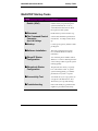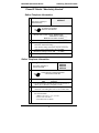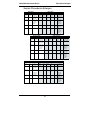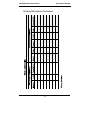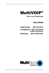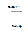
1
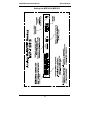
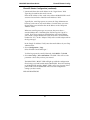
Voice / Fax over IP Networks
Quick Start Guide
for
Voice/IP Gateways
Digital Models (T1, E1, ISDN-PRI):
MVP-2400/2410/3010
Analog Models: MVP-210/410/810
Quick Start Guide
82000250, Revision A
Analog MultiVOIP Units (Models MVP210, MVP410, and MVP810)
Digital MultiVOIP Units (Models MVP2400, MVP2410, MVP3010,)
This publication may not be reproduced, in whole or in part, without prior
expressed written permission from Multi-Tech Systems, Inc. All rights
reserved.
Copyright © 2002, by Multi-Tech Systems, Inc.
Multi-Tech Systems, Inc. makes no representations or warranties with respect
to the contents hereof and specifically disclaims any implied warranties of
merchantability or fitness for any particular purpose. Furthermore, Multi-Tech
Systems, Inc. reserves the right to revise this publication and to make changes
from time to time in the content hereof without obligation of Multi-Tech
Systems, Inc. to notify any person or organization of such revisions or changes.
Record of Revisions
Revision
Description
A
(05/08/02)
Initial Release of Joint MultiVOIP Q.S.Guide.
Patents
This Product is covered by one or more of the following U.S. Patent Numbers:
5.301.274; 5.309.562; 5.355.365; 5.355.653; 5.452.289; 5.453.986. Other Patents
Pending.
Trademark
Trademark of Multi-Tech Systems, Inc. is the Multi-Tech logo. Windows and
NetMeeting are registered trademarks of Microsoft.
Multi-Tech Systems, Inc.
2205 Woodale Drive
Mounds View, Minnesota 55112
(763) 785-3500 or (800) 328-9717
U.S. Fax: 763-785-9874
Technical Support: (800) 972-2439
http://www.multitech.com
2
CONTENTS
Introduction
Safety Warnings
Lithium Battery Caution
Safety Warnings Telecom
MultiVOIP Startup Tasks
Phone/IP Details *Absolutely Needed*
Before Starting the Installation
Gather IP Information
Gather Telephone Information
Gather Telephone Information
Gather Telephone Information
Obtain Email Address for VOIP
(for email call log reporting)
Identify Remote VOIP Site to Call
Idenitfy VOIP Protocol to be Used
Placement
The Command/Control Computer (Specs & Settings)
Quick Hookups
Load MultiVOIP Control Software onto PC
Phone/IP Starter Configuration
Phonebook Starter Configuration (with remote voip)
Outbound Phonebook
Inbound Phonebook
Phonebook Tips
Phonebook Example
Connectivity Test
Troubleshooting
Limited Warranty
Technical Support
Contacting Technical Support
Regulatory Information
EMC, Safety, and R&TTE Directive Compliance
FCC Declaration
3
4
4
4
4
5
6
6
6
7
7
8
8
8
9
9
10
13
14
16
16
20
23
27
32
36
37
38
38
39
39
39
Safety Warnings
MultiVOIP Quick Start Guide
Introduction
This manual will get your MultiVOIP up and running quickly.
For more details, see the MultiVOIP User Guide.
Safety Warnings
Lithium Battery Caution
A lithium battery on the voice/fax channel board provides backup
power for the timekeeping capability. The battery has an estimated life
expectancy of ten years.
When the battery starts to weaken, the date and time may be incorrect.
If the battery fails, the board must be sent back to Multi-Tech Systems
for battery replacement.
Warning: There is danger of explosion if the battery is incorrectly
replaced.
Safety Warnings Telecom
1. Never install telephone wiring during a lightning storm.
2. Never install a telephone jack in wet locations unless the jack is
specifically designed for wet locations.
3. This product is to be used with UL and cUL listed computers.
4. Never touch uninsulated telephone wires or terminals unless the
telephone line has been disconnected at the network interface.
5. Use caution when installing or modifying telephone lines.
6. Avoid using a telephone (other than a cordless type) during an
electrical storm. There may be a remote risk of electrical shock from
lightning.
7. Do not use a telephone in the vicinity of a gas leak.
8. To reduce the risk of fire, use only 26 AWG or larger
telecommunication line cord.
4
MultiVOIP Quick Start Guide
Startup Tasks
MultiVOIP Startup Tasks
Task
Summary
● Collecting Phone/IP
Details (vital!)
The MultiVOIP must be configured to
interface with your particular phone
system and IP network. To do so,
certain details must be known about
those phone and IP systems.
● Placement
Decide where you’ll mount the voip.
● The Command/Control
Computer:
Some modest minimum specifications
must be met. A COM port must be set
up.
● Hookup
Connect power, phone, and data cables
per diagram.
● Software Installation
This is the configuration program.
It’s a standard Windows software
installation.
● Phone/IP Starter
Configuration
You will enter phone numbers and IP
addresses. You’ll use default parameter
values where possible to get the system
running quickly.
● Phonebook Starter
Configuration
The phonebook is where you specify
how calls will be routed. To get the
system running quickly, you’ll make
phonebooks for just two voip sites.
● Connectivity Test
You’ll find out if your voip system can
carry phone calls between two sites.
That means you’re up and running!
● Troubleshooting
Detect and remedy any problems that
might have prevented connectivity.
Specs & Settings
5
Gathering Phone/IP Details
MultiVOIP Quick Start Guide
Phone/IP Details *Absolutely Needed*
Before Starting the Installation
The MultiVOIP will interface with both the IP network and the phone
system. You must gather information about the IP network and about
the phone system so that the MultiVOIP can be configured to operate
with them properly.
Gather IP Information
➼ Ask your computer network
administrator.
(
Info needed to operate:
all MultiVOIP models.
IP Network Parameters:
Record for each VOIP Site
in System
• IP Address
• IP Mask
• Gateway
• Domain Name Server (DNS) Info
(not implemented; for future use)
Gather Telephone Information
➼ T1 Phone Parameters
Info needed to operate:
MVP2400
MVP2410
Ask phone company or
PBX maintainer.
(
T1 Telephony Parameters:
Record for this VOIP Site
• Which frame format is used? ESF___ or D4___
• Which CAS or PRI protocol is used? ______________
• Clocking: Does the PBX or telco switch use
internal or external clocking? _________________
Note that the setting used in the voip unit will be the
opposite of the setting used by the telco/PBX.
• Which line coding is used? AMI___ or B8ZS___
• Pulse shape level?: (most commonly 0 to 40 meters)
6
MultiVOIP Quick Start Guide
Gathering Phone/IP Details
Phone/IP Details *Absolutely Needed*
Gather Telephone Information
➼ E1 Phone Parameters
Info needed to operate:
MVP3010
Ask phone company or
PBX maintainer.
(
E1 Telephony Parameters:
Record for this VOIP Site
• Which frame format is used? Double Frame_____
MultiFrame w/ CRC4_____
MultiFrame w/ CRC4 modified_____
• Which CAS or PRI protocol is used? ______________
• Clocking: Does the PBX or telco switch use
internal or external clocking? _________________
Note that the setting used in the voip unit will be the
opposite of the setting used by the telco/PBX.
• Which line coding is used? AMI___ or HDB3___
• Pulse shape level?: (most commonly 0 to 40 meters)
Gather Telephone Information
➼ Analog Phone Parameters
Ask phone company or
telecom manager.
(
Needed for:
MVP810
MVP410
MVP210
Analog Telephony Interface Parameters:
Record for this VOIP Site
• Which interface type (or “signaling”) is used?
E&M_____ FXS/FXO_____
• If FXS, determine whether the line will be used for a
phone, fax, or KTS (key telephone system)
• If FXO, determine if line will be an analog PBX
extension or an analog line from a telco central office
• If E&M, determine these aspects of the E&M trunk
line from the PBX:
• What is its Type (1, 2, 3, 4, or 5)?
• Is it 2-wire or 4-wire?
• Is it Dial-Tone or Wink?
7
Gathering Phone/IP Details
MultiVOIP Quick Start Guide
Phone/IP Details Often Needed/Wanted
Obtain Email Address for VOIP (for email call log reporting)
required if log reports of
VOIP call traffic
are to be sent by email
Optional
SMTP Parameters
Preparation Task:
To: I.T. Department
Ask Mail Server
administrator to set up
email account (with
password) for the
MultiVOIP unit itself.
Be sure to give a unique
identifier to each
individual MultiVOIP
unit.
re: email account for VOIP
[email protected]
Get the IP address of the
mail server computer, as
well.
Identify Remote VOIP Site to Call
When you’re done installing the MultiVOIP, you’ll want to confirm that
it is configured and operating properly. To do so, it’s good to have
another voip that you can call for testing purposes. You’ll want to
confirm end-to-end connectivity. You’ll need IP and telephone
information about that remote site.
If this is the very first voip in the system, you’ll want to coordinate the
installation of this MultiVOIP with an installation of another unit at a
remote site.
Identify VOIP Protocol to be Used
Will you use H.323 or SIP? Each has advantages and disadvantages.
Although it is possible to mix protocols in a single VOIP system, it is
highly desirable to use the same VOIP protocol for all VOIP units in
the system.
8
MultiVOIP Quick Start Guide
Voip Placement & PC Settings
Placement
Mount your MultiVOIP in a safe and convenient location where cables
for your network and phone system are accessible. Rack-mounting
instructions are in Chapter 3: Mechanical Installation & Cabling of the User
Guide.
The Command/Control Computer (Specs & Settings)
The computer used for command and control of the MultiVOIP
(a) must be an IBM-compatible PC,
(b) must use a Microsoft operating system,
(c) must be connected to your local network (Ethernet) system, and
(d) must have an available serial COM port.
The configuration tasks and control tasks the PC will have to do with
the MultiVOIP are not especially demanding. Still, we recommend
using a reasonably new computer. The computer that you use to
configure your MultiVOIP need not be dedicated to the MultiVOIP
after installation is complete.
COM port on controller PC. You’ll need an available COM port on the
controller PC. You’ll need to know which COM port is available for use
with the MultiVOIP (COM1, COM2, etc.).
9
Quick Hookups
MultiVOIP Quick Start Guide
Quick Hookups
Hookup for MVP2410 & MVP3010
10
MultiVOIP Quick Start Guide
Quick Hookups
Hookup for MVP410 & MVP810
11
Quick Hookups
MultiVOIP Quick Start Guide
Hookup for MVP2400
DIGITAL VOICE
ETHERNET COMMAND
1
TRUNK
10/100
POWER
RS232
0
Power Connection
T1
:
PBX
PSTN
Telephony Connection
Command Port Connection
Network Connection
Hub
Hookup for MVP210
CH1
CH2
E&M FXS/FXO E&M
FXS/FXO
ETHERNET
RS232
10/100 COMMAND POWER
10BASET
COMMAND PORT
POWER
Voice/Fax Channel 1 - 2
Connections
E&M
FXO/FXS
GND
Power Connection
FXS
E&M
FXO
Command Port Connection
PSTN
Ethernet Connection
12
MultiVOIP Quick Start Guide
Software Installation
Load MultiVOIP Control Software onto PC
For more details, see Chapter 4: Software Installation in User Guide.
1. MultiVOIP must be properly cabled. Power must be turned on.
2. Insert MultiVOIP CD into drive. Allow 10-20 seconds for Autorun to
start. If Autorun fails, go to
My Computer | CD ROM drive | Open. Click Autorun icon.
3. At first dialog box, click Install Software.
4. At ‘welcome’ screen, click Next.
5. Follow on-screen instructions. Accept default program folder
location and click Next.
6. Accept default icon folder location. Click Next. Files will be copied.
7. Select available COM port on command/control computer.
8. At completion screen, click Finish.
9. At the prompt “Do you want to run MultiVOIP Configuration?,”
click No. Software installation is complete.
13
Phone/IP Starter Config.
MultiVOIP Quick Start Guide
Phone/IP Starter Configuration
Full details here:
MVP2400
MVP2410
MVP3010
MVP210
MVP410
MVP810
Chapter 5: Technical Configuration for
Digital T1/E1 MultiVOIPs
in User Guide.
Chapter 6: Technical Configuration for
Analog MultiVOIPs
in User Guide
1. Open MultiVOIP program: Start | MultiVOIP xxx | Configuration.
2. Go to Configuration | IP. Enter the IP parameters for your voip site.
3. Go to Configuration | Voice/Fax. Select Coder | “Automatic.” At
the right-hand side of the dialog box, click Default. If you know any
specific parameter values that will apply to your system, enter them.
Click Copy Channel. Select Copy to All. Click Copy. At main
Voice/Fax Parameters screen, click OK to exit from the dialog box.
4. Enter telephone system information.
Analog MultiVOIPs
MVP-210/410/810
Digital MultiVOIPs
MVP-2400/2410/3010
Go to
Configuration | Interface.
Enter parameters obtained from
phone company or PBX
administrator.
Go to
Configuration | T1/E1/ISDN.
Enter parameters obtained from
phone company or PBX
administrator.
5. Go to Configuration | Regional Parameters. Select the
Country/Region that fits your situation. Click Default and confirm.
Click OK to exit from the dialog box.
6. Do you want the phone-call logs produced by the MultiVOIP to be
sent out by email (to your Voip Administrator or someone else)?
If NO, skip to step 8.
If YES, continue with step 7.
7. Go to Configuration | SMTP.
SMTP lets you send phone-call log records to the Voip Administrator
by email. Select Enable SMTP.
You should have already obtained an email address for the
MultiVOIP itself (this serves as the origination email account for
email logs that the MultiVOIP can email out automatically).
14
MultiVOIP Quick Start Guide
Phone/IP Starter Config.
Phone/IP Starter Configuration (continued)
7. (continued) Enter this email address in the “Login Name” field.
Type the password for this email account.
Enter the IP address of the email server where the MultiVOIP’s email
account is located in the “Mail Server IP Address” field.
Typically the email log reports are sent to the Voip Administrator
but they can be sent to any email address. Decide where you want
the email logs sent and enter that email address in the “Recipient
Address” field.
Whenever email log messages are sent out, they must have a
standard Subject line. Something like “Phone Logs for Voip N” is
useful. If you have more than one MultiVoip unit in the building,
you’ll need a unique identifier for each one (select a useful name or
number for “N”). In this “Subject” field, enter a useful subject title for
the log messages.
In the “Reply-To Address” field, enter the email address of your Voip
Administrator.
8. Go to Configuration | Logs.
Select “Enable Console Messages.”
To allow log reports by email (if desired), click SMTP. Click OK.
9. Go to Save Setup | Save and Reboot. Click OK. This will save the
parameter values that you have just entered.
The MultiVOIP’s “BOOT” LED will light up while the configuration
file is being saved and loaded into the MultiVOIP. Don’t do anything
to the MultiVOIP until the “BOOT “LED is off (a loss of power at this
point could cause the MultiVOIP unit to lose the configuration
settings you have made).
END OF PROCEDURE.
15
Phonebook Starter Config.
MultiVOIP Quick Start Guide
Phonebook Starter Configuration (with remote voip)
To do this part of the quick setup, you need to know of another voip
that you can call to conduct a test. It should be at a remote location,
typically somewhere outside of your building. You must know the
phone number and IP address for that site. We are assuming here that
the MultiVOIP will operate in conjunction with a PBX.
You must configure both the Outbound Phonebook and the Inbound
Phonebook. A starter configuration only means that two voip locations
will be set up to begin the system and establish voip communication.
Outbound Phonebook
1. Open the MultiVOIP program
(Start | MultiVOIP xxx | Configuration
2. Go to Phone Book | PhoneBook Modify | Outbound Phonebook
| Add Entry.
3. On a sheet of paper, write down the calling code of the remote voip
(area code, country code, city code, etc.) that you’ll be calling.
Follow the example that best fits your situation.
North America,
Long-Distance Example
Technician in Seattle (area
206) must set up one voip
there, another in Chicago
(area 312, downtown).
Answer:
Write down 312.
Euro, National Call
Example
Technician in central
London (area 0207) to set
up voip there, another in
Birmingham (area 0121).
Answer:
write down 0121.
Euro, International Call Example
Technician in Rotterdam (country 31; city 010) to
set up one voip there, another in Bordeaux
(country 33; area 05).
Answer:
write down 3305.
16
MultiVOIP Quick Start Guide
Phonebook Starter Config.
4. Suppose you want to call a phone number outside of your building
using a phone station that is an extension from your PBX system (if
present). What digits must you dial? Often a “9” or “8” must be
dialed to “get an outside line” through the PBX (i.e., to connect to the
PSTN). Generally, “1 “or “11” or “0” must be dialed as a prefix for
calls outside of the calling code area (long-distance calls, national
calls, or international calls).
On a sheet of paper, write down the digits you must dial before you
can dial a remote area code.
North America,
Long-Distance Example
Seattle-Chicago system.
Euro, National Call
Example
London/Birming. system.
Seattle voip works with
PBX that uses “8” for all
voip calls. “1” must
immediately precede area
code of dialed number.
London voip works with
PBX that uses “9” for all
out-of-building calls
whether by voip or by
PSTN. “0” must
immediately precede area
code of dialed number.
Answer:
write down 81.
Answer:
write down 90.
Euro, International Call Example
Rotterdam/Bordeaux system.
Rotterdam voip works with PBX where “9” is
used for all out-of-building calls. “0” must
precede all international calls.
Answer:
write down 90.
17
Phonebook Starter Config.
MultiVOIP Quick Start Guide
5. In the “Destination Pattern” field of the Add/Edit Outbound
Phonebook screen, enter the digits from step 4 followed by the digits
from step 3.
North America,
Long-Distance Example
Seattle-Chicago system.
Answer:
enter 81312 as
Destination Pattern in Outbound
Phone-book of
Seattle voip.
Euro, National Call
Example
London/Birming. system.
Leading zero of
Birmingham area code is
dropped when combined
with national-dialing
access code. (Such
practices vary by country.)
Answer:
enter 90121 as
Destination Pattern in Outbound
Phonebook of
London voip.
Not 900121.
Euro, International Call Example
Rotterdam/Bordeaux system.
enter 903305 as Destination Pattern in
Outbound Phonebook of Rotterdam voip.
Answer:
18
MultiVOIP Quick Start Guide
Phonebook Starter Config.
6. Tally up the number of digits that must be dialed to reach the remote
voip site (including prefix digits of all types). Enter this number in
the “Total Digits” field.
North America,
Long-Distance Example
Euro, National Call
Example
Seattle-Chicago system.
London/Birming. system.
To complete Seattle-toChicago call, 81312 must be
followed by the 7-digit local
phone number in Chicago.
To complete London-toBirmingham call, 90121 must be
followed by the 7-digit local
phone number in Birmingham.
Answer: enter 12 as number
Answer: enter 12 as number
of Total Digits in
Outbound Phonebook of Seattle
voip.
of Total Digits in
Outbound Phonebook of London
voip.
Euro, International Call Example
Rotterdam/Bordeaux system.
To complete Rotterdam-to-Bordeaux call, 903305 must
be followed by 8-digit local phone number in Bordeaux.
Answer: enter 14 as number of Total Digits in
Outbound Phonebook of Rotterdam voip.
7. In the “Remove Prefix” field, enter the initial PBX access digit (“8” or
“9”).
North America,
Long-Distance Example
Euro, National Call
Example
Seattle-Chicago system.
London/Birming. system.
Answer: enter 8 in “Remove
Answer: enter 9 in “Remove
Prefix” field of
Seattle Outbound
Phonebook.
Prefix” field of
London Outbound
Phonebook.
Euro, International Call Example
Rotterdam/Bordeaux system.
Answer: enter 9 in “Remove Prefix” field of Outbound
Phonebook for Rotterdam voip.
Some PBXs will not ‘hand off’ the “8” or “9” to the voip. But for those PBX
units that do, it’s important to enter the “8” or “9” in the “Remove Prefix”
field in the Outbound Phonebook. This precludes the problem of having to
make two inbound phonebook entries at remote voips, one to account for
situations where “8” is used as the PBX access digit, and another for when
“9” is used.
19
Phonebook Starter Config.
MultiVOIP Quick Start Guide
8. Select the voip protocol that you will use (H.323 or SIP).
9. Click OK. to exit from the Add/Edit Outbound Phonebook screen.
Inbound Phonebook
1. Open the MultiVOIP program.
(Start | MultiVOIP xxx | Configuration
2. Go to Phone Book | PhoneBook Modify | Outbound Phonebook
| Add Entry.
3. In the “Remove Prefix” field, enter your local calling code (area code,
country code, city code, etc.) preceded by any other “access digits”
that are required to reach your local site from the remote voip
location (think of it as though the call were being made through the
PSTN – even though it will not be).
North America,
Long-Distance Example
Euro, National Call
Example
Seattle-Chicago system.
London/Birming. system.
Seattle is area 206. Chicago
employees must dial 81
before dialing any Seattle
number on the voip system.
Inner London is 0207 area.
Birmingham employees must
dial 9 before dialing any
London number on the voip
system.
Answer: 1206 is prefix to be
removed by local
(Seattle) voip.
Answer: 0207 is prefix to be
removed by local
(London) voip.
Euro, International Call Example
Rotterdam/Bordeaux system.
Rotterdam is country code 31, city code 010. Bordeaux
employees must dial 903110 before dialing any
Rotterdam number on the voip system.
Answer: 03110 is prefix to be removed by local
(Rotterdam) voip.
20
MultiVOIP Quick Start Guide
Phonebook Starter Config.
4. In the “Add Prefix” field, enter any digits that must be dialed from
your local voip to gain access to the PSTN.
North America,
Long-Distance Example
Euro, National Call
Example
Seattle-Chicago system.
London/Birming. system.
On Seattle PBX, “9” is used to
get an outside line.
On London PBX, “9” is used
to get an outside line.
Answer: 9 is prefix to be
added by local
(Seattle) voip.
Answer: 9 is prefix to be
added by local
(London) voip.
Euro, International Call Example
Rotterdam/Bordeaux system.
On Rotterdam PBX, “9” is used to get an outside line.
Answer: 9 is prefix to be added by local (Rotterdam)
voip.
5. In the “Channel Number” field, enter “0.” A zero value means the
voip unit will assign the call to an available channel. If desired,
specific channels can be assigned to specific incoming calls (i.e., to
any set of calls received with a particular incoming dialing pattern).
21
Phonebook Starter Config.
MultiVOIP Quick Start Guide
6. In the “Description” field, it is useful to describe the ultimate
destination of the calls. For example, in a New York City voip
system, “incoming calls to Manhattan office,” might describe a
phonebook entry, as might the descriptor “incoming calls to NYC
local calling area.” The description should make the routing of calls
easy to understand. (40 characters max.)
North America,
Long-Distance Example
Euro, National Call
Example
Seattle-Chicago system.
London/Birming. system.
Possible Description:.
Free Seattle access, all
employees
Possible Description:.
Local-rate London access,
all empl.
Euro, International Call Example
Rotterdam/Bordeaux system.
Possible Description:. Local-rate Rotterdam access, all
empl.
7. Repeat steps 2-6 for each inbound phonebook entry. When all entries
are complete, go to step 8.
8. Click OK to exit the inbound phonebook screen.
9. Click on Save Setup. Highlight Save and Reboot. Click OK.
Your starter inbound phonebook configuration is complete.
22
Phonebook Tips
MultiVOIP Quick Start Guide
Phonebook Tips
Preparing the phonebook for your voip system is a complex task that, at
first, seems quite daunting. These tips may make the task easier.
1. Use Dialing Patterns, Not Complete Phone Numbers. You will not
generally enter complete phone numbers in the voip phonebook.
Instead, you’ll enter “destination patterns” that involve area codes and
other digits. If the destination pattern is a whole area code, you’ll be
assigning all calls to that area code to go to a particular voip which has
a unique IP address. If your destination pattern includes an area code
plus a particular local phone exchange number, then the scope of calls
sent through your voip system will be narrowed (only calls within that
local exchange will be handled by the designated voip, not all calls in
that whole area code). In general, when there are fewer digits in your
destination pattern, you are asking the voip to handle calls to more
destinations.
2. The Four Types of Phonebook Digits Used. Important!
“Destination patterns” to be entered in your phonebook will generally
consist of:
(a) calling area codes,
(b) access codes,
(c) local exchange numbers, and
(d) specialized codes.
Although voip phonebook entries may look confusing at first, it’s
useful to remember that all the digits in any phonebook entry must be
of one of these four types.
(a) calling area codes. There are different names for these around the
world: “area codes,” “city codes,” “country codes,” etc. These codes,
are used when making non-local calls. They always precede the phone
number that would be dialed when making a local call.
23
Phonebook Tips
MultiVOIP Quick Start Guide
(b) access codes. There are digits (PSTN access codes) that must be
dialed to gain access to an operator, to access the publicly switched
‘long-distance’ calling system(North America), to access the publicly
switched ‘national’ calling system (Europe and elsewhere), or to access
the publicly switched ‘international’ calling system (worldwide).
There are digits (PBX access codes) that must be dialed by phones
connected to PBX systems or key systems. Often a “9” must be dialed
on a PBX phone to gain access to the PSTN (‘to get an outside line’).
Sometimes “8” must be dialed on a PBX phone to divert calls onto a
leased line or to a voip system. However, sometimes PBX systems are
‘smart’ enough to route calls to a voip system without a special access
code (so that “9” might still be used for all calls outside of the building).
There are also digits (special access codes) that must be dialed to gain
access to a particular discount long-distance carrier or to some other
closed or proprietary telephone system.
(c) local exchange numbers. Within any calling area there will be many
local exchange numbers. A single exchange may be used for an entire
small town. In cities, an exchange may be used for a particular
neighborhood (although exchanges in cities do not always cover easily
discernible areas). Organizations like businesses, governments,
schools, and universities are also commonly assigned exchange
numbers for their exclusive use. In some cases, these organizationalassigned exchanges can become non-localized because the exchange is
assigned to one facility and linked, by the organization’s private
network, to other sometimes distant locations.
(d) specialized codes. Some proprietary voip units assign, to sites and
phone stations, numbers that are not compatible with PSTN
numbering. This can also occur in PBX or key systems. These
specialized numbers must be handled on a case-by-case basis.
3. Knowing When to Drop Digits.
Example
When calling area codes and
access codes are used in
combination, a leading “1” or “0”
must sometimes be dropped.
Area code for Inner London is
listed as “0207.” However, in
international calls the leading
“0” is dropped.
U.K.
Country
Code
Phonebook Entry ➠
International
Access Code
24
Leading Zero
Dropped from
Area Code
MultiVOIP Quick Start Guide
Phonebook Tips
4. Using a Comma.
Commas are used in telephone
dialing strings to indicate a pause
to allow a dial tone to appear
(common on PBX and key
systems). Commas may be used
only in the “Add Prefix” field of
the Inbound Phonebook.
,
Detail
= 1-second pause
in many PBX systems
(not needed in all)
5. Ease of Use. The phonebook setup determines how easy the voip
system is to use. Generally, you’ll want to make it so dialing a voip call
is very similar to dialing any other number (on the PSTN or through the
PBX).
6. Avoid Unintentional Calls to Official/Emergency Numbers. Dialing a
voip call will typically be somewhat different than ordinary dialing.
Because of this, it’s possible to set up situations, quite unwittingly,
where phone users may be predisposed to call official numbers without
intending to do so. Conversely, a voip/PBX system might also make it
difficult to place an official/emergency call when one intends to do so.
Study for your phonebook setup and do some dialing on the system to
avoid these pitfalls.
7. Inbound/Outbound Pattern Matching. In general, the Inbound
Phonebook entries of the local voip unit will match the Outbound
Phonebook entries of the remote voip unit. Similarly, the Outbound
Phonebook entries of the local voip unit will match the Inbound
Phonebook entries of the remote voip unit. There will often be nonmatching entries, but it’s nonetheless useful to notice the matching
between the phonebooks.
8. Simulating Network in-lab/on-benchtop. One common method of
configuring a voip network is to to set up a local IP network in a lab,
connect voip units to it, and perhaps have phones connected on channel
banks to make test calls.
25
Phonebook Tips
MultiVOIP Quick Start Guide
NOTES
26
MultiVOIP Quick Start Guide
Phonebook Example
Phonebook Example
One Common Situation
Boise Office
PBX System.
Main Number:
333-2700
Area: 208
PSTN
90 extensions
204.16.49.73
24-Channel
Digital VoIP
(MVP2410)
Voip Example. This company has offices in three
different cities. The PBX units all operate alike.
Notably, they all give access to outside lines using
“9.” They all are ‘smart’ enough to identify voip calls
without using a special access digit (“8” is used in
some systems). Finally, the system operates so that
employees in any office can dial employees in any
other office using only three digits. Here are the
phonebooks needed for that system.
Inbound Phonebook
Each Inbound Phonebook contains
two entries. The first entry (4 digits)
specifies how incoming calls from the
other voip sites will be handled if
they go out onto the local PSTN.
Essentially, all those calls come to the
receiving voip with a pattern
beginning with 1+area code. The local
voip removes those four digits
because they aren’t needed when
dialing locally. The local voip
attaches a “9” at the beginning of the
number to get an outside line. The
PBX then completes the call to the
PSTN.
Santa Fe Office
Area: 505
204.16.49.74
8-Channel
Analog VoIP
(MVP810)
IP
Network
PBX System.
Main Number:
444-3200
40 extensions
The second Inbound Phonebook entry
(8 digits) is for receiving calls from
company employees in the other two
cities. The out-of-town employee
simply dials 3 digits. The first of the
three digits is uniquely used at each
site and so acts as a destination
pattern (Boise extensions are 7xx,
Santa Fe extensions 2xx, Flagstaff
extensions 6xx).
PSTN
Each Outbound Phonebook contains two
pairs of entries, two entries for each
remote site. Whenever an out-of-town
employee dials a 12-digit number
beginning with the listed 5-digit
destination pattern (9+1+area code) of
another company location, the PBX
hands the call to the voip system. The
local voip strips off the “9” and directs
the call to the IP address of the remote
voip. The remote voip receives the call
and hands it to its PBX. The PBX then
completes the call to the PSTN.
As the remote voip sends out the call,
it automatically attaches all of the
foregoing digits that would normally
have to be dialed using the PSTN.
The local (receiving) voip sees the
extended pattern in its Inbound
Phonebook and so strips off the long
telltale pattern of digits needed for 3digit calling. It must finally add back
the last digit before handing the call
to the PBX, which completes the call
to a specific extension.
Flagstaff Office
Area: 520
The one-digit Outbound destination
patterns pertain to 3-digit calling
between company employees.
204.16.49.75
8-Channel
Analog VoIP
(MVP810)
PBX System.
Main Number:
777-5600
PSTN
30 extensions
27
Phonebook Example
MultiVOIP Quick Start Guide
Boise Office
PBX System.
Main Number:
333-2700
Area: 208
Boise Voip
Boise Voip
Inbound Phonebook
PSTN
Outbound Phonebook
Prefix to
Remove
1208
Prefix
to Add
Description
Incoming Calls
9
12083332
2
Incoming calls
to PSTN,
Boise Area
Incoming calls
to extensions
of company’s
PBX system
in Boise
90 extensions
204.16.49.73
24-Channel
Digital VoIP
(MVP2410)
Destin.
Pattern
91505
Total
Digits
Prefix to
Remove
Prefix
to Add
12
9
none
IP
Addr
204.16
.49.74
2
3
none
1505
444
3
204.16
.49.74
91520
12
9
none
6
3
none
1520
777
5
204.1
6.49.7
5
204.1
6.49.7
5
Description
Outgoing Calls
Outgoing calls
to Santa Fe
area
3-digit calls to
Santa Fe
employees
Outgoing calls
to Flagstaff
area
3-digit calls to
Flagstaff
employees
IP
Network
Santa Fe Office
Area: 505
Santa Fe Voip
Santa Fe Voip
Inbound Phonebook
Prefix to
Remove
1505
150544432
Prefix
to Add
Description
Incoming Calls
9,
Incoming calls
to PSTN,
Santa Fe local
calls
Incoming calls
to extensions
of company’s
PBX system
in Santa Fe
2
204.16.49.74
Outbound Phonebook
Destin.
Pattern
91208
Total
Digits
Prefix to
Remove
Prefix
to Add
IP
Addr
Description
Outgoing Calls
12
9
none
204.
16.49.
73
Outgoing calls
to Boise area
7
3
none
1208
333
2
204.1
6.49.
73
91520
12
9
none
6
3
none
1520
777
5
204.
16.49.
75
204.
16.49.
75
Outgoing calls
to extensions
of company’s
Boise PBX (3digit dialing)
Outgoing calls
to Flagstaff
area
3-digit calls to
Flagstaff
employees
8-Channel
Analog VoIP
(MVP810)
PBX System.
Main Number:
444-3200
40 extensions
PSTN
Flagstaff Office
Area: 520
Flagstaff Voip
204.16.49.75
PBX System.
Main Number:
777-5600
Flagstaff Voip
Inbound Phonebook
8-Channel
Analog VoIP
(MVP810)
Prefix to
Remove
1520
Prefix
to Add
Description
Incoming Calls
9
15207775
5
Incoming calls
to PSTN,
Flagstaff local
calls
Incoming calls
to extensions
of company’s
PBX system
in Flagstaff
PSTN
30 extensions
28
Outbound Phonebook
Destin.
Pattern
91505
Total
Digits
Prefix to
Remove
Prefix
to Add
IP
Addr
Description
Outgoing Calls
12
9
none
204.16
.49.74
Outgoing calls
to Santa Fe
area
2
3
none
1505
444
3
204.16
.49.74
3-digit calls to
Santa Fe
employees
91208
12
9
none
7
3
none
1208
333
2
204.16
.49.73
204.16
.49.73
Outgoing calls
to Boise area
3-digit calls to
Boise
employees
MultiVOIP Quick Start Guide
Phonebook Example
Sample Phonebooks Enlarged
Boise Voip
Boise Voip
Inbound Phonebook
Outbound Phonebook
Prefix to
Remove
1208
Prefix
to Add
Description
Incoming Calls
9,
120833327
7
Incoming calls
to PSTN,
Boise Area
Incoming calls
to extensions
of company’s
PBX system
in Boise
Destin.
Pattern
91505
Total
Digits
Prefix to
Remove
Prefix
to Add
IP
Addr
Description
Outgoing Calls
12
9
none
204.
16.49.
74
2
3
none
1505
444
3
204.
16.49.
74
91520
12
9
none
6
3
none
1520
777
5
204.
16.49.
75
204.
16.49.
75
Outgoing calls
to Santa Fe
area
3-digit calls to
Santa Fe
employees
(extensions
200 to 240)
Outgoing calls
to Flagstaff
area
3-digit calls to
Flagstaff
employees
(extensions
600-630)
Santa Fe Voip
Santa Fe Voip
Inbound Phonebook
Outbound Phonebook
Prefix to
Remove
1505
Prefix
to Add
Description
Incoming Calls
9,
150544432
2
Incoming calls
to PSTN,
Santa Fe local
calls
Incoming calls
to extensions
of company’s
PBX system
in Santa Fe
Destin.
Pattern
91208
Total
Digits
Prefix to
Remove
Prefix
to Add
IP
Addr
Description
Outgoing Calls
12
9
none
204.
16.49.
73
Outgoing calls
to Boise area
7
3
none
1208
333
2
204.
16.49.
73
91520
12
9
none
6
3
none
1520
777
5
204.
16.49.
75
204.
16.49.
75
3-digit calls to
Boise
employees
(extensions
700-790)
Outgoing calls
to Flagstaff
area
3-digit calls to
Flagstaff
employees
(extensions
600-630)
Flagstaff Voip
Flagstaff Voip
Inbound Phonebook
Outbound Phonebook
Prefix to
Remove
1520
Prefix
to Add
Description
Incoming Calls
9,
152077756
6
Incoming calls
to PSTN,
Flagstaff local
calls
Incoming calls
to extensions
of company’s
PBX system
in Flagstaff
Destin.
Pattern
91505
Total
Digits
Prefix to
Remove
Prefix
to Add
IP
Addr
Description
Outgoing Calls
12
9
none
204.16
.49.74
Outgoing calls
to Santa Fe
area
2
3
none
1505
444
3
204.16
.49.74
91208
12
9
none
204.16
.49.73
7
3
none
1208
333
2
204.16
.49.73
3-digit calls to
Santa Fe
employees
(extensions
200-240)
Outgoing calls
to Boise area
3-digit calls to
Boise
employees
(extensions
700-790)
29
Phonebook Example
MultiVOIP Quick Start Guide
Phonebook Worksheet
Voip Location/ID:____________________________
Inbound Phonebook
Prefix to
Remove
Prefix
to Add
Outbound Phonebook
Description
Incoming Calls
Destin.
Pattern
Total
Digits
Prefix to
Remove
Prefix
to Add
IP
Addr
Description
Outgoing Calls
Other Details:
Voip Location/ID:____________________________
Inbound Phonebook
Prefix to
Remove
Prefix
to Add
Description
Incoming Calls
Outbound Phonebook
Destin.
Pattern
Total
Digits
Prefix to
Remove
Prefix
to Add
IP
Addr
Description
Outgoing Calls
Other Details:
Voip Location/ID:____________________________
Inbound Phonebook
Prefix to
Remove
Prefix
to Add
Description
Incoming Calls
Outbound Phonebook
Destin.
Pattern
Total
Digits
Other Details:
30
Prefix to
Remove
Prefix
to Add
IP
Addr
Description
Outgoing Calls
MultiVOIP Quick Start Guide
Phonebook Example
Enlarged Phonebook Worksheet
31
Connectivity Test
MultiVOIP Quick Start Guide
Connectivity Test
The procedures “Phone/IP Starter Configuration” and “Phonebook
Starter Configuration” must be completed before you can do this
procedure.
1. These connections must be made:
for digital MultiVOIPs
(MVP-2400/2410/3010
Connections
for analog MultiVOIPs
(MVP-210/410/810)
MultiVOIP to local PBX
MultiVOIP to local phone
station
–OR-MultiVOIP to extension of
key phone system
MultiVOIP to command PC
MultiVOIP to command PC
MultiVOIP to Internet
MultiVOIP to Internet
2. Inbound Phonebook and Outbound Phonebook must both be set up
with at least one entry in each. These entries must allow for
connection between two voip units.
3. Console messages must be enabled. (If this has not been done
already, go, in the MultiVOIP GUI, to Configuration | Logs and
select the “Console Messages” checkbox.
4. You now need to free up the COM port connection (currently being
used by the MultiVOIP program) so that the HyperTerminal program
can use it. To do this, you can either (a) click on Connection in the
sidebar and select “Disconnect” from the drop-down box, or (b) close
down the MultiVOIP program altogether.
5. Open the HyperTerminal program.
32
MultiVOIP Quick Start Guide
Connectivity Test
6. Use HyperTerminal to receive and record console messages from the
MultiVOIP unit. To do so, set up HyperTerminal as follows (setup
shown is for Windows NT4; details will differ slightly in other MS
operating systems):
In the upper toolbar of the HyperTerminal screen, click on
the Properties button.
In the “Connect To” tab of the Connection Properties
dialog box, click on the Configure button.
In the next dialog box, on the “General” tab, set “Maximum
Speed” to 115200 bps.
On the “Connection” tab, set connection preferences to:
Data bits:
8
Parity:
none
Stop bits:
1
Click OK twice to exit settings dialog boxes.
7. Make VOIP call.
for digital MultiVOIPs
(MVP-2400/2410/3010
for analog MultiVOIPs
(MVP-210/410/810)
Make call from an extension
of the local PBX.
Make call on a local phone
line accessing PSTN directly
or through key system
33
Connectivity Test
MultiVOIP Quick Start Guide
8. Read console messages recorded on HyperTerminal.
Console Messages from Originating VOIP. The voip unit that
originates the call will send back messages like that shown below.
[00026975] CAS[0] : RX : ABCD = 1, 1, 1, 1,Pstn State[1]
TimeStamp : 26975
[00027190] CAS[0] : TX : ABCD = 1, 1, 1, 1
[00027190] PSTN: cas seizure detected on 0
[00027440] CAS[0] : TX : ABCD = 0, 0, 0, 0
[00033290] PSTN:call detected on 0 num=17637175662*
[00033290] H323IF[0]:destAddr =
TA:200.2.10.5:1720,NAME:Mounds
View,TEL:17637175662,17637175662
[00033290] H323IF[0]:srcAddr = NAME:New
York,TA:200.2.9.20
[00033440] H323IF [0]:cmCallStateProceeding
[00033500] H323[0]: Remote Information (Q931): MultiVOIP
- T1
[00033565] CAS[0] : TX : ABCD = 1, 1, 1, 1
[00033675] H323IF [0]: MasterSlaveStatus=Slave
[00033675] H323IF[0]:FastStart Setup Not Used
[00033690] CAS[0] : TX : ABCD = 1, 1, 1, 1
[00033755] H323IF[0]: Coder used 'g7231'
[00033810] PSTN:pstn call connected on 0
34
MultiVOIP Quick Start Guide
Connectivity Test
Console Messages from Terminating VOIP. The voip unit connected
to the phone where the call is answered will send back messages like
that shown below.
[00170860] H323[0]: New incoming call
[00170860] PSTNIF : Placing call on channel 0 Outbound
digit 7175662
[00170885] CAS[0] : TX : ABCD = 1, 1, 1, 1
[00171095] H323IF [0]: MasterSlaveStatus=Master
[00171105] CAS[0] : RX : ABCD = 1, 1, 1, 1,Pstn State[7]
TimeStamp : 171105
[00171105] H323IF[0]: Coder used 'g7231'
[00171110] H323IF[0]:FastStart Setup Not Used
[00171110] H323IF[0]: Already opened the outgoing logical
channel
[00171110] H323IF[0]: Coder used 'g7231'
[00171315] CAS[0] : RX : ABCD = 0, 0, 0, 0,Pstn State[9]
TimeStamp : 171315
[00172275] PSTN: dialing digit ended on 0
[00172285] PSTN: pstn proceeding indication on 0
[00172995] CAS[0] : RX : ABCD = 1, 1, 1, 1,Pstn State[12]
TimeStamp : 172995
[00173660] CAS[0] : TX : ABCD = 1, 1, 1, 1
[00173760] PSTN:pstn call connected on 0
9. When you see the following message, end-to-end voip connectivity
has been achieved.
“PSTN: pstn call connected on X”
where x is the number of the voip channel carrying the call
10. If the HyperTerminal messages do not confirm connectivity, go to
the Troubleshooting procedure below.
35
Troubleshooting
MultiVOIP Quick Start Guide
Troubleshooting
If you cannot establish connectivity between two voips in the system,
follow the steps below to determine the problem.
1. Ping both MultiVOIP units to confirm connectivity to the network.
2. Verify the telephone connections.
A. For MVP2400, MVP2410, or MVP3010.
Check cabling. Are connections well seated? To correct receptacle?
Is the ONL LED on?
(If on, ONL indicates that the MultiVOIP is online on the
network.)
Are T1/E1/PRI Parameter settings correct?
B. For MVP210, MVP410, or MVP810.
Check cabling. Are connections well seated? To correct receptacle?
Are telephone Interface Parameter settings correct?
3. Verify phonebook configuration.
4. Observe console messages while placing a call. Look for error
messages indicating phonebook problems, network problems, voicecoder mismatches, etc.
36
Warranty
MultiVOIP Quick Start Guide
Limited Warranty
Multi-Tech Systems, Inc. (“MTS”) warrants that its products will be free
from defects in material or workmanship for a period of two years from
the date of purchase, or if proof of purchase is not provided, two years
from date of shipment. MTS MAKES NO OTHER WARRANTY,
EXPRESSED OR IMPLIED, AND ALL IMPLIED WARRANTIES OF
MERCHANTABILITY AND FITNESS FOR A PARTICULAR PURPOSE
ARE HEREBY DISCLAIMED. This warranty does not apply to any
products which have been damaged by lightning storms, water, or
power surges or which have been neglected, altered, abused, used for a
purpose other than the one for which they were manufactured, repaired
by the customer or any party without MTS’s written authorization, or
used in any manner inconsistent with MTS’s instructions.
MTS’s entire obligation under this warranty shall be limited (at MTS’s
option) to repair or replacement of any products which prove to be
defective within the warranty period, or, at MTS’s option, issuance of a
refund of the purchase price. Defective products must be returned by
Customer to MTS’s factory—transportation prepaid.
MTS WILL NOT BE LIABLE FOR CONSEQUENTIAL DAMAGES
AND UNDER NO CIRCUMSTANCES WILL ITS LIABILITY EXCEED
THE PURCHASE PRICE FOR DEFECTIVE PRODUCTS.
37
Warranty, Service, & Tech Support
MultiVOIP User Guide
Technical Support
Multi-Tech Systems has an excellent staff of technical support personnel
available to help you get the most out of your Multi-Tech product. If
you have any questions about the operation of this unit, or experience
difficulty during installation you can contact Tech Support via the
following:
Contacting Technical Support
Country
By E-mail
By telephone
France
[email protected]
(33) 1-64 61 09
81
India
support@
multitechindia.com
(91) 124-340778
U.K.
support@
multitech.co.uk
(44) 118 959 7774
U.S. &
Canada
tsupport@
multitech.com
(800) 972-2439
Rest of
World
support@
multitech.com
(763) 785-3500
Internet: http://www.multitech.com/ _forms/email_tech_support.htm
Please have your product information available, including model and
serial number.
38
MultiVOIP Quick Start Guide
Regulatory Info
Regulatory Information
EMC, Safety, and R&TTE Directive Compliance
The CE mark is affixed to this product to confirm compliance with the
following European Community Directives:
Council Directive 89/336/EEC of 3 May 1989 on the approximation of the
laws of Member States relating to electromagnetic compatibility,
and
Council Directive 73/23/EEC of 19 February 1973 on the harmonization of
the laws of Member States relating to electrical equipment designed for use
within certain voltage limits,
and
Council Directive 1999/5/EC of 9 March 1999 on radio equipment and
telecommunications terminal equipment and the mutual recognition of their
conformity.
FCC Declaration
NOTE: This equipment has been tested and found to comply with the
limits for a Class A digital device, pursuant to Part 15 of the FCC Rules.
These limits are designed to provide reasonable protection against
harmful interference when the equipment is operated in a commercial
environment. This equipment generates, uses and can radiate radio
frequency energy, and if not installed and used in accordance with the
instructions, may cause harmful interference to radio communications.
Operation of this equipment in a residential area is likely to cause
harmful interference in which case the user will be required to correct
the interference at his own expense.
This device complies with Part 15 of the FCC rules.
Operation is subject to the following two conditions:
(1) This device may not cause harmful interference.
(2) This device must accept any interference that may cause
undesired operation.
Warning: Changes or modifications to this unit not expressly approved
by the party responsible for compliance could void the user’s authority
to operate the equipment.
39
82000250