1
MITSUBISHI ELECTRIC
GOT Series
Human Machine Interface
Operation Manual
Graphic Operator Terminals
F920GOT, F930GOT, F940GOT,
F940/F943 Handy GOT
Art.-Nr.: 139833
01 03 2003
JY992D94701
Version E
MITSUBISHI ELECTRIC
INDUSTRIAL AUTOMATION
Graphic Operation Terminal GOT-F900
Foreword
• This manual contains text, diagrams and explanations which will guide the reader in the
correct installation and operation of GOT -F900.
• Before attempting to install or use GOT-F900 this manual should be read and understood.
• If in doubt at any stage of the installation of GOT-F900 always consult a professional
electrical engineer who is qualified and trained to the local and national standards which
apply to the installation site.
• If in doubt about the operation or use of GOT-F900 please consult the nearest Mitsubishi
Electric distributor.
• This manual is subject to change without notice.
Graphic Operation Terminal GOT-F900
GRAPHIC OPERATION TERMINAL
GOT-F900
OPERATION MANUAL
Manual number : JY992D94701
Manual revision : E
Date
: April 2003
i
Graphic Operation Terminal GOT-F900
ii
Graphic Operation Terminal GOT-F900
FAX BACK
Mitsubishi has a world wide reputation for its efforts in continually developing and pushing back
the frontiers of industrial automation. What is sometimes overlooked by the user is the care
and attention to detail that is taken with the documentation. However, to continue this process
of improvement, the comments of the Mitsubishi users are always welcomed. This page has
been designed for you, the reader, to fill in your comments and fax them back to us. We look
forward to hearing from you.
Fax numbers:
Your name: ...................................................
Mitsubishi Electric....
.....................................................................
America
(01) 847-478-2253
Your company: .............................................
Australia
(02) 638-7072
.....................................................................
Germany
(0 21 02) 4 86-1 12
Your location:................................................
Spain
(34) 93-589-1579
.....................................................................
United Kingdom
(01707) 278-695
Please tick the box of your choice
What condition did the manual arrive in?
!Good
!Minor damage
Will you be using a folder to store the manual? !Yes
!No
What do you think to the manual presentation?!Tidy
!Unfriendly
Are the explanations understandable?
!Yes
!Not too bad
!Unusable
!Unusable
Which explanation was most difficult to understand: ..................................................................
....................................................................................................................................................
Are there any diagrams which are not clear?
!Yes
!No
If so,which: ..................................................................................................................................
What do you think to the manual layout?
!Good
!Not too bad
!Unhelpful
If there one thing you would like to see improved, what is it? .....................................................
....................................................................................................................................................
....................................................................................................................................................
Could you find the information you required easily using the index and/or the contents, if
possible please identify your experience: ...................................................................................
....................................................................................................................................................
....................................................................................................................................................
....................................................................................................................................................
....................................................................................................................................................
Do you have any comments in general about the Mitsubishi manuals? .....................................
....................................................................................................................................................
....................................................................................................................................................
....................................................................................................................................................
....................................................................................................................................................
Thank you for taking the time to fill out this questionnaire. We hope you found both the product
and this manual easy to use.
iii
Graphic Operation Terminal GOT-F900
iv
Graphic Operation Terminal GOT-F900
Guidelines for the Safety of the User and Protection of the Graphic operation
terminal GOT-F900
This manual provides information for the use of the Graphic operation terminal GOT-F900. The
manual has been written to be used by trained and competent personnel. The definition of
such a person or persons is as follows;
a) Any engineer who is responsible for the planning, design and construction of automatic
equipment using the product associated with this manual should be of a competent
nature, trained and qualified to the local and national standards required to fulfill that
role. These engineers should be fully aware of all aspects of safety with regards to
automated equipment.
b) Any commissioning or service engineer must be of a competent nature, trained and
qualified to the local and national standards required to fulfill that job. These engineers
should also be trained in the use and maintenance of the completed product. This
includes being completely familiar with all associated documentation for the said product.
All maintenance should be carried out in accordance with established safety practices.
c) All operators of the completed equipment (see Note) should be trained to use this
product in a safe manner in compliance to established safety practices. The operators
should also be familiar with documentation which is associated with the operation of the
completed equipment.
Note : Note: the term ‘completed equipment’ refers to a third party constructed device which
contains or uses the product associated with this manual.
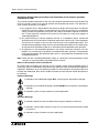
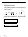
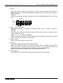
Notes on the Symbols Used in this Manual
At various times throughout this manual certain symbols will be used to highlight points of
information which are intended to ensure the users personal safety and protect the integrity of
equipment. Whenever any of the following symbols are encountered its associated note must
be read and understood. Each of the symbols used will now be listed with a brief description of
its meaning.
Hardware Warnings
1) Indicates that the identified danger WILL cause physical and property damage.
2) Indicates that the identified danger could POSSIBLY cause physical and property
damage.
3) Indicates a point of further interest or further explanation.
Software Warnings
4) Indicates special care must be taken when using this element of software.
5) Indicates a special point which the user of the associate software element should
be aware of.
6) Indicates a point of interest or further explanation.
v
Graphic Operation Terminal GOT-F900
• Under no circumstances will Mitsubishi Electric be liable or responsible for any
consequential damage that may arise as a result of the installation or use of this equipment.
• All examples and diagrams shown in this manual are intended only as an aid to
understanding the text, not to guarantee operation. Mitsubishi Electric will accept no
responsibility for actual use of the product based on these illustrative examples.
• Please contact a Mitsubishi Electric distributor for more information concerning applications
in life critical situations or high reliability.
vi
Graphic Operation Terminal GOT-F900
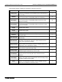
Table of Contents
Manual configuration and various data ....................................................1
1. Introduction............................................................................................1-1
1.1 Outline ................................................................................................................. 1-1
1.2 Format of manual ................................................................................................ 1-3
1.2.1 Contents described in manual ................................................................................... 1-3
1.2.2 Abbreviations used in text ......................................................................................... 1-4
1.3 Expressions and basic functions of operation keys ............................................. 1-6
1.3.1 Expressions of operation keys .................................................................................. 1-6
1.3.2 Basic operations ........................................................................................................ 1-6
1.4 System configuration ........................................................................................... 1-7
1.4.1 Connection of GOT with peripheral units .................................................................. 1-7
1.5
1.6
1.7
1.8
Applicable PLC .................................................................................................... 1-9
GOT version upgrade history ............................................................................ 1-13
Screen creation software version upgrade history ............................................ 1-17
Preservation of screen data and backup ........................................................... 1-19
2. Specifications ........................................................................................2-1
2.1 General specifications ......................................................................................... 2-1
2.2 Display section specifications .............................................................................. 2-2
3. Name of Display Unit.............................................................................3-1
3.1 Front panel .......................................................................................................... 3-1
3.2 Rear panel ........................................................................................................... 3-3
3.3 Functions of ports ................................................................................................ 3-4
4. Function.................................................................................................4-1
4.1 Function list ......................................................................................................... 4-1
5. Start Up .................................................................................................5-1
5.1 Start up procedure ............................................................................................... 5-1
5.2 System settings ................................................................................................... 5-3
5.2.1
5.2.2
5.2.3
5.2.4
5.2.5
5.2.6
5.2.7
5.2.8
5.2.9
5.2.10
5.2.11
5.2.12
5.2.13
Outline of operation environment setting................................................................... 5-3
LANGUAGE .............................................................................................................. 5-5
PLC TYPE ................................................................................................................. 5-6
SERIAL PORT........................................................................................................... 5-7
OPENING SCREEN .................................................................................................. 5-7
MAIN MENU CALL KEY............................................................................................ 5-8
SET CLOCK .............................................................................................................. 5-9
SET BACKLIGHT ...................................................................................................... 5-9
BUZZER .................................................................................................................. 5-10
LCD CONTRAST .................................................................................................... 5-10
CLEAR USER DATA ............................................................................................... 5-11
HANDY GOT SETTING .......................................................................................... 5-12
AUXILIARY SETTING ............................................................................................. 5-13
5.3 Each mode selection procedure ........................................................................ 5-14
5.4 Security function (screen protection function) ................................................... 5-16
5.4.1
5.4.2
5.4.3
5.4.4
Outline of security function ...................................................................................... 5-16
Input of entry code................................................................................................... 5-17
Reset of entry code ................................................................................................. 5-19
Upgrading of security function ................................................................................. 5-20
vii
Graphic Operation Terminal GOT-F900
6. Creation of Display Screens ..................................................................6-1
6.1 Outline of compatibility of screen data................................................................. 6-2
6.1.1 Functions dedicated to screen creation software FX-PCS-DU/WIN-E ...................... 6-3
6.1.2 Common functions .................................................................................................... 6-4
6.1.3 Functions dedicated to GT Designer ......................................................................... 6-6
6.2 Transfer of screen data ....................................................................................... 6-7
6.3 Appropriation of screen data ............................................................................... 6-9
6.3.1 Conversion from FX-50DU-TK(S)-E to F940GOT ..................................................... 6-9
6.4 Concept on screen display ................................................................................ 6-10
6.4.1
6.4.2
6.4.3
6.4.4
Screen display position ........................................................................................... 6-10
Number of display screens and screen numbers .................................................... 6-10
Number of display elements and data capacity....................................................... 6-10
Attribute of display element ..................................................................................... 6-11
6.5 Screen call function and overlay function .......................................................... 6-14
6.5.1 The writing function of the initial display screen number (GT Designer is used.).... 6-15
6.5.2 Screen call function ................................................................................................. 6-16
6.5.3 Overlay function ...................................................................................................... 6-17
6.6 Interface Devices and system information......................................................... 6-25
6.6.1 Interface Devices (setting in FX-PCS-DU/WIN-E)................................................... 6-25
6.6.2 System Information (setting in GT Designer) .......................................................... 6-28
7. USER SCREEN MODE.........................................................................7-1
7.1
7.2
7.3
7.4
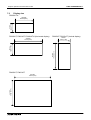
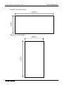
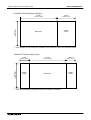
7.5
Display format...................................................................................................... 7-2
Display size ......................................................................................................... 7-3
Outline of USER SCREEN MODE ...................................................................... 7-6
Number of registered screen construction elements ........................................... 7-8
Change of displayed data .................................................................................. 7-10
7.5.1 Data change condition............................................................................................. 7-10
7.6 Data change using touch keys .......................................................................... 7-11
7.6.1
7.6.2
7.6.3
7.6.4
7.6.5
7.6.6
Common items in data change using touch keys .................................................... 7-11
Data change procedure using touch key ................................................................ 7-12
Key window display in F930GOT-K......................................................................... 7-13
Decimal point input function .................................................................................... 7-16
Key window display position specification ............................................................... 7-17
Creation of key window ........................................................................................... 7-19
7.7 Data change using key pad (F920GOT-K and F930GOT-K) ............................ 7-22
7.7.1 Data change operation using key pad ..................................................................... 7-22
7.7.2 Cursor key operation ............................................................................................... 7-24
7.8 Numeric setting completion flag and data changing flag ................................... 7-29
8. HPP Mode .............................................................................................8-1
8.1
8.2
8.3
8.4
Outline of HPP mode ........................................................................................... 8-1
PROGRAM LIST ................................................................................................. 8-3
PARAMETER .................................................................................................... 8-12
DEVICE MONITOR ........................................................................................... 8-14
8.4.1 Device/comment monitor......................................................................................... 8-16
8.4.2 Changing set values and current values of T, C and D ........................................... 8-17
8.4.3 Forced ON/OFF....................................................................................................... 8-19
8.5
8.6
8.7
8.8
LIST MONITOR ................................................................................................. 8-20
ACTIVE STATE MONITOR ............................................................................... 8-21
BFM MONITOR ................................................................................................. 8-22
PC DIAGNOSIS................................................................................................. 8-24
viii
Graphic Operation Terminal GOT-F900
9. Sampling MODE....................................................................................9-1
9.1 Outline of sampling mode .................................................................................... 9-1
9.2 Outline of sampling condition setting ................................................................... 9-3
9.2.1
9.2.2
9.2.3
9.2.4
SAMPLE COND. ....................................................................................................... 9-5
START COND. .......................................................................................................... 9-6
END COND. .............................................................................................................. 9-7
SAMPLING DEV. ...................................................................................................... 9-9
9.3 Display of sampling result.................................................................................. 9-10
9.3.1 DISPLAY LIST......................................................................................................... 9-10
9.3.2 DISPLAY GRAPH ................................................................................................... 9-10
9.4 CLEAR DATA .................................................................................................... 9-11
9.5 Control signals in PLC ....................................................................................... 9-12
9.5.1 When FX-PCS-DU/WIN-E is used........................................................................... 9-12
9.5.2 When GT Designer.................................................................................................. 9-12
10.Alarm MODE ......................................................................................10-1
10.1 Outline of alarm function.................................................................................... 10-1
10.2 Alarm function in screen mode .......................................................................... 10-2
10.2.1 Set item ................................................................................................................... 10-3
10.2.2 Operation in F920GOT-K ........................................................................................ 10-5
10.2.3 Alarm history clear using key code.......................................................................... 10-6
10.3 Alarm function in alarm mode ............................................................................ 10-8
10.3.1
10.3.2
10.3.3
10.3.4
10.3.5
Operation when alarms have occurred ................................................................... 10-9
Alarm list................................................................................................................ 10-11
Alarm history display ............................................................................................. 10-13
Alarm frequency display ........................................................................................ 10-14
Alarm history clear................................................................................................. 10-15
11.Test MODE.........................................................................................11-1
11.1
11.2
11.3
11.4
11.5
Outline of test mode .......................................................................................... 11-1
USER SCREEN................................................................................................. 11-2
DATA BANK ...................................................................................................... 11-3
DEBUG .............................................................................................................. 11-4
Communication monitor..................................................................................... 11-7
11.5.1 Function Outline ...................................................................................................... 11-7
11.5.2 Applicable version ................................................................................................... 11-7
11.5.3 Screen Display ........................................................................................................ 11-7
12.Other MODE.......................................................................................12-1
12.1
12.2
12.3
12.4
12.5
12.6
Outline of other mode ........................................................................................ 12-1
SET TIME SWITCH ........................................................................................... 12-2
DATA TRANSFER............................................................................................. 12-4
PRINT OUT ....................................................................................................... 12-5
ENTRY CODE ................................................................................................... 12-7
SET UP MODE .................................................................................................. 12-8
13.Connection to Bar Code Reader ........................................................13-1
13.1 Outline of function.............................................................................................. 13-1
13.2 Applicable version ............................................................................................. 13-1
13.3 Connection ........................................................................................................ 13-1
ix
Graphic Operation Terminal GOT-F900
14.Screen Hard Copy Function ...............................................................14-1
14.1 Outline of hardware copy operation................................................................... 14-1
14.2 Applicable version ............................................................................................. 14-2
14.3 Starting and aborting printing ............................................................................ 14-2
14.3.1
14.3.2
14.3.3
14.3.4
Start and abortion by triggers .................................................................................. 14-2
Start and abortion by touch keys ............................................................................. 14-2
Hard copy output signal (GT Designer) ................................................................... 14-3
Printing image ......................................................................................................... 14-4
15.Buzzer ................................................................................................15-1
15.1 Applicable Version ............................................................................................. 15-1
15.2 GB and buzzer sounds ...................................................................................... 15-1
15.3 Use example of buzzer sounds by GB (GT Designer)....................................... 15-2
16.Observe Status Function....................................................................16-1
16.1
16.2
16.3
16.4
16.5
16.6
16.7
16.8
Outline of observe status function ..................................................................... 16-1
Applicable version ............................................................................................. 16-2
Observe cycle .................................................................................................... 16-2
Setting the triggers ............................................................................................ 16-3
Setting the operation ......................................................................................... 16-4
Trigger and number of devices .......................................................................... 16-7
Cautions when many triggers and devices are set ............................................ 16-8
Use example (utilization of clock data) .............................................................. 16-9
17.Key Pad (F920GOT-K and F930GOT-K) ...........................................17-1
17.1 Function keys .................................................................................................... 17-1
17.1.1 Assignment of function keys.................................................................................... 17-2
17.1.2 Assignment of LEDs (F930GOT-K) ......................................................................... 17-3
17.2 Handling of ten-keys, cursor control keys, "SET" key, "DEV" key,
"ESC" key and "ENT" key.................................................................................. 17-4
x
Graphic Operation Terminal GOT-F900
18.Creation of Display Screens (FX-PCS-DU/WIN-E) ............................18-1
18.1
18.2
18.3
18.4
Parts list............................................................................................................. 18-1
Application and setting item............................................................................... 18-4
Registration of object ......................................................................................... 18-7
Display objects .................................................................................................. 18-8
18.4.1
18.4.2
18.4.3
18.4.4
18.4.5
18.4.6
18.4.7
18.4.8
Text ......................................................................................................................... 18-8
Line.......................................................................................................................... 18-9
Box ........................................................................................................................ 18-10
Filled Box............................................................................................................... 18-11
Circle ..................................................................................................................... 18-12
Filled Circle............................................................................................................ 18-13
Image .................................................................................................................... 18-14
Date and time ........................................................................................................ 18-15
18.5 Data display objects ........................................................................................ 18-16
18.5.1 Library Text ........................................................................................................... 18-16
18.5.2 Number.................................................................................................................. 18-18
18.5.3 Bar Graph .............................................................................................................. 18-21
18.5.4 Circle Graph .......................................................................................................... 18-24
18.5.5 Proportional Bar Graph ......................................................................................... 18-25
18.5.6 Proportional Pie Graph .......................................................................................... 18-26
18.5.7 Panel Meter ........................................................................................................... 18-27
18.5.8 Indicator................................................................................................................. 18-28
18.5.9 Label Indicator ....................................................................................................... 18-29
18.5.10Text Indicator ........................................................................................................ 18-30
18.5.11Image Indicator ..................................................................................................... 18-31
18.5.12Overlay Screen ..................................................................................................... 18-32
18.5.13Library Image........................................................................................................ 18-33
18.5.14Trend Graph ......................................................................................................... 18-34
18.5.15Line Graph ............................................................................................................ 18-37
18.5.16Ascii ...................................................................................................................... 18-39
18.6 Data transfer objects ....................................................................................... 18-42
18.6.1 Assignment of function keys.................................................................................. 18-42
18.6.2 Touch Key ............................................................................................................. 18-43
18.6.3 Switch .................................................................................................................... 18-47
18.6.4 Send Data Bank (recipe function) ......................................................................... 18-49
18.6.5 Write Constant....................................................................................................... 18-50
18.6.6 Increment .............................................................................................................. 18-51
18.6.7 Decrement ............................................................................................................. 18-52
18.6.8 Data Setting........................................................................................................... 18-53
18.6.9 Keyboard ............................................................................................................... 18-56
18.6.10Change Screen..................................................................................................... 18-60
18.6.11Alarm history display function ............................................................................... 18-61
18.6.12Alarm list display function ..................................................................................... 18-63
18.6.13Buzzer .................................................................................................................. 18-66
18.7 Text library ....................................................................................................... 18-67
18.8 Image library .................................................................................................... 18-68
18.9 Data file ........................................................................................................... 18-69
18.10Setting of backlight (F920GOT-K)................................................................... 18-71
18.11Assignment of LEDs (F930GOT-K) ................................................................ 18-72
xi
Graphic Operation Terminal GOT-F900
19.Changeover of Display Screen (FX-PCS-DU/WIN-E) ........................19-1
19.1 Outline of changeover of display screen ........................................................... 19-1
19.2 "Change Screen" object..................................................................................... 19-2
19.2.1 Contents of setting .................................................................................................. 19-2
19.2.2 Operation of screen changeover ............................................................................. 19-4
19.2.3 Timing of screen changeover .................................................................................. 19-5
19.3 Screen changeover by touch key ...................................................................... 19-6
19.4 Screen changeover using function keys ............................................................ 19-9
19.5 Screen changeover from PLC ......................................................................... 19-11
19.5.1 Screen changeover using bit devices.................................................................... 19-11
19.5.2 Screen changeover by data register ..................................................................... 19-12
19.6 Screen changeover by screen number stored in memory ............................... 19-14
19.7 Changeover to system screen ......................................................................... 19-16
19.7.1 Display of system screen ...................................................................................... 19-16
19.8 Application of screen changeover ................................................................... 19-17
20.Creation of Display Screen (GT Designer).........................................20-1
20.1
20.2
20.3
20.4
20.5
Project auxiliary settings .................................................................................... 20-1
Parts list............................................................................................................. 20-8
Application and setting item............................................................................. 20-10
Figure display function..................................................................................... 20-12
Data display function ....................................................................................... 20-13
20.5.1 Display of numerics ............................................................................................... 20-13
20.5.2 Ascii display........................................................................................................... 20-15
20.5.3 Clock display ......................................................................................................... 20-18
20.6 Message display function ................................................................................ 20-19
20.6.1 Comment display................................................................................................... 20-19
20.6.2 Alarm history display ............................................................................................. 20-20
20.6.3 Alarm list display ................................................................................................... 20-23
20.7 Animation display function ............................................................................... 20-25
20.7.1 Part display............................................................................................................ 20-25
20.7.2 Lamp ..................................................................................................................... 20-26
20.7.3 Panel meter ........................................................................................................... 20-27
20.8 Graph display function ..................................................................................... 20-28
20.8.1
20.8.2
20.8.3
20.8.4
Line graph ............................................................................................................. 20-29
Trend graph ........................................................................................................... 20-30
Bar graph............................................................................................................... 20-31
Statistics graph display function ............................................................................ 20-33
20.9 Touch keys ...................................................................................................... 20-34
20.9.1
20.9.2
20.9.3
20.9.4
Common items for all touch keys .......................................................................... 20-35
Bit function............................................................................................................. 20-37
Word function ........................................................................................................ 20-39
Creation of keys to enter numerics and ASCII codes............................................ 20-40
20.10Operation panel .............................................................................................. 20-41
20.10.1Assignment of function keys ................................................................................. 20-42
20.11Data input function .......................................................................................... 20-43
20.11.1Numerical input function ....................................................................................... 20-43
20.11.2Ascii code input function ....................................................................................... 20-45
20.12Creation of comment....................................................................................... 20-48
20.13Recipe function ............................................................................................... 20-49
20.14Setting of backlight (F920GOT-K)................................................................... 20-51
20.15Assignment of LEDs (F930GOT-K) ................................................................ 20-52
xii
Graphic Operation Terminal GOT-F900
21.Changeover of Display Screen (GT Designer)...................................21-1
21.1 Outline of changeover of display screen ........................................................... 21-1
21.2 Changeover of display screen ........................................................................... 21-2
21.2.1 Contents of setting .................................................................................................. 21-2
21.2.2 Contents of screen changeover operation .............................................................. 21-2
21.3 Changeover of base screen (changeover from PLC) ........................................ 21-3
21.3.1 Outline of changeover of base screen..................................................................... 21-3
21.3.2 Example of base screen changeover ...................................................................... 21-4
21.4 Screen changeover by touch key or function key .............................................. 21-5
21.4.1 Changeover using a fixed value .............................................................................. 21-5
21.4.2 Changeover to Previous screens ............................................................................ 21-6
21.5 Changeover to system screen ........................................................................... 21-8
21.5.1 Display example of system screen .......................................................................... 21-8
21.6 Application of screen changeover ..................................................................... 21-9
21.6.1 Application example 1 ............................................................................................. 21-9
21.6.2 Application example 2 ........................................................................................... 21-11
22.Appendix ............................................................................................22-1
22.1
22.2
22.3
22.4
22.5
22.6
22.7
Number of registered screen construction elements ......................................... 22-1
Comparison with screen creation software........................................................ 22-3
Differences in functions among display units and connected PLC .................... 22-5
Key pad operation on system screens (F930GOT-K) ....................................... 22-9
System Screen Number .................................................................................. 22-10
Key Code List .................................................................................................. 22-11
Device Name Which Can Be Monitored .......................................................... 22-12
22.7.1 Devices in GOT-F900............................................................................................ 22-12
22.7.2 PLC by Mitsubishi.................................................................................................. 22-14
22.7.3 PLC Units Manufactured by Other Companies ..................................................... 22-19
22.8 Key Code List .................................................................................................. 22-27
22.9 Label pattern (F930GOT-K)............................................................................. 22-29
xiii
Graphic Operation Terminal GOT-F900
xiv
Graphic Operation Terminal GOT-F900
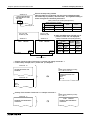
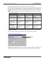
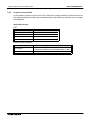
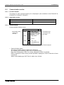
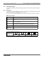
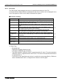
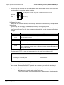
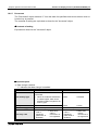
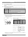
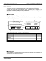
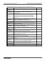
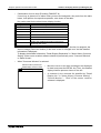
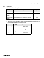
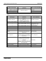
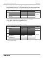
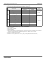
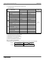
Manual configuration and various data
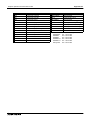
Manual configuration and various data
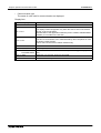
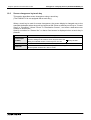
The table below shows the manual configuration related to the graphic operation terminal
GOT-F900.
Manual name
Manual
number
Description
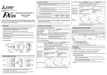
F920GOT-BBD5-K-E
Installation Manual
(included with product)
This manual contains explanations for the
JY992D02201 specifications, installation and maintenance, etc of
F920GOT-BBD5-K-E graphic operation terminals.
F930GOT-BBD5-K-E
Installation Manual
(included with product)
This manual contains explanations for the
JY992D02501 specifications, installation and maintenance, etc of
F930GOT-BBD-K-E graphic operation terminals.
F930GOT Series
(F93*GOT-BWD-E)
Installation Manual
(included with product)
This manual contains explanations for the
JY992D95701 specifications, installation and maintenance, etc. of
F930GOT Series graphic operation terminals.
F940GOT Series
(F940GOT-*WD-E)
Installation Manual
(included with product)
This manual contains explanations for the
JY992D94201 specifications, installation and maintenance, etc of
F940GOT Series graphic operation terminals.
F940GOT Handy Series
(F94*GOT-*BD-H-E)
HARDWARE MANUAL
(included with product)
This manual contains explanations for the
specifications, installation and maintenance, etc of
JY992D86901
F940GOT Handy Series handy graphic operation
terminals.
F940WGOT Series
Installation Manual
(included with product)
This manual contains explanations for the
JY992D93901 specifications, installation and maintenance, etc of
F940WGOT Series graphic operation terminals.
SW!D5C-GOTR-PACKE
OPERATING MANUAL
(included with screen creation
software)
This manual contains explanations for the operation
of GT Designer (SW*D5C-GOTR-PACKE) screen
creation software.
FX-PCS-DU/WIN-E
SOFTWARE MANUAL
(included with screen creation
software)
JY992D68301
This manual contains explanations for the operation
of FX-PCS-DU/WIN-E screen creation software.
GOT-F900 SERIES
OPERATION MANUAL
(this manual)
This manual contains explanations for the operation
JY992D94701 and use of the GOT-F900 Series graphic operation
terminals.
GOT-F900 SERIES
HARDWARE MANUAL
(CONNECTION)
(separate volume)
This manual contains explanations for the wiring and
JY992D94801 installation, etc of the GOT-F900 series graphic
operation terminals.
F9GT-40UMB MANUAL
F9GT-40UMB HARDWARE MANUAL (packed
together with product)
JY992D74101
Describes the operating procedure of the adapter for
data transfer F9GT-40UMB.
1
Graphic Operation Terminal GOT-F900
Manual configuration and various data
MEMO
2
Graphic Operation Terminal GOT-F900
1.
Introduction 1
Introduction
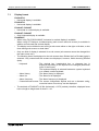
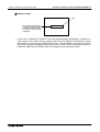
This chapter describes the product and system configuration of the graphic operation terminal.
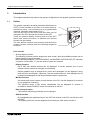
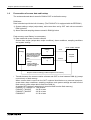
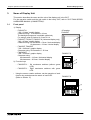
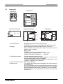
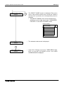
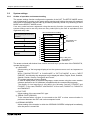
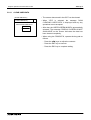
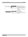
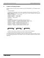
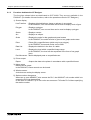
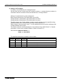
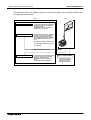
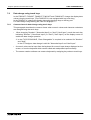
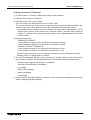
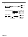
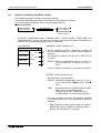
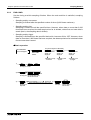
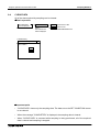
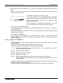
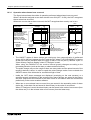
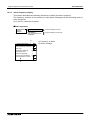
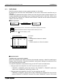
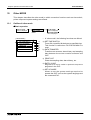
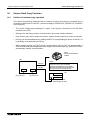
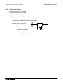
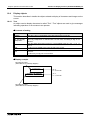
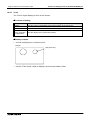
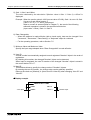
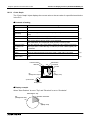
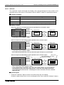
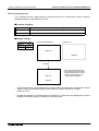
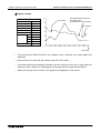
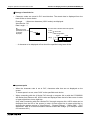
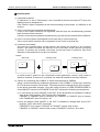
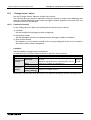
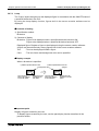
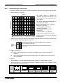
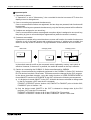
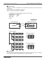
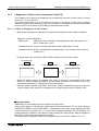
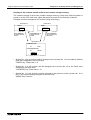
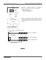
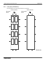
1.1
Outline
The graphic operation terminal (hereafter abbreviated to
GOT) is to be mounted on the face of a control panel or
operations panel, and connected to a programmable
controller (hereafter abbreviated to PLC).
Various devices can be monitored and data can be
changed in the PLC through the screens of the GOT.
There are several display screens built-in to the GOT
which offer various functions. In addition user defined
screens can be created.
The user defined screens (user screens) and the built-in
screens (system screens) have the following respective
functions.
P L C
P ro g ra m
p o rt
G O T m a in b o d y
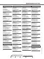
User screens
• Screen display function
The following functions can be assigned to each screen. Also the available screens can be
limited using the security function.
Both software packages, FX-PCS-DU/WIN-E, and SW"D5C-GOTR-PACKE (""" indicates
a numeric not less than "1".) can be used to create user screens.
Display function
- Up to 500 user defined screens can be displayed. In screen creation, two or more
screens can be overlaid or changed over arbitrarily.
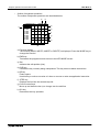
- Simple graphics such as straight lines, circles and rectangles can be displayed, along
with numerics and English, Japanese, Chinese and Korean text. Also bitmaps can be
imported and displayed as well as pre-defined screen components.
Monitor function
- Set values and current values of word devices in the PLC can be displayed in numerics
or bar graphs for monitoring.
- The specified range of the screen components can be displayed in reverse in
accordance with the ON/OFF status of bit devices in the PLC.
Data change function
- The numeric data being monitored can be changed.
Switch function
- By manipulating the operation keys in the GOT, bit devices in the PLC can be set to ON
and OFF.
The display panel face can be assigned as touch keys to offer switch functions.
1-1
Graphic Operation Terminal GOT-F900
Introduction 1
System screens
• Monitor function
List program (only in the FX Series)
- Programs can be read, written and monitored in the form of an instruction list program.
(Available only in the F940GOT and F940WGOT)
Buffer memory (only in the FX2N and FX2NC Series)
- The contents of buffer memories (BFMs) of special blocks can be read, written and
monitored. (Available only in the F940GOT and F940WGOT)
Device monitor
- The ON/OFF status of each device, the set value and current value of each timer,
counter and data register in the PLC can be monitored and changed.
- Specified bit devices can be forced ON or OFF.
Unlike the monitor function described previously, screen data can be displayed by
inputting a desired device number from the keyboard.
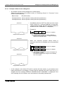
• Data sampling function
The current value of specified data registers are acquired in a constant cycle or when the
trigger condition is satisfied.
- Sampling data can be displayed in the form of list or graph.
- Sampling data can be output to a printer in the form of list.
• Alarm function
Alarm messages can be assigned to up to 256 consecutive bit devices in the PLC (32 in the
F920GOT-K). When a bit device becomes ON, the assigned message is displayed
(overlapped) on the user screen.
In addition, a specified user screen can be displayed by setting a corresponding bit device
to ON.
- When a bit device becomes ON, a corresponding message is displayed on the user
screen. The message list can also be displayed.
- Up to 1000 alarms (turning ON of bit devices) can be stored as the alarm history. *1
- The alarm frequency of each device can be stored as historical data.
*1 Using the screen creation software, the alarm history can be read by a personal
computer and then sent to a printer.
• Other functions
Many other functions are built in.
- A real-time clock, current time and data can be set and displayed (excluding the
F920GOT-K).
- The GOT can function as an interface to enable data communication between the PLC
and a personal computer in which the relay ladder creation software is operating. At this
time, the GOT screen can also be displayed.
- The screen contrast and the buzzer sound volume can be adjusted.
1-2
Graphic Operation Terminal GOT-F900
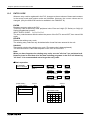
1.2
Format of manual
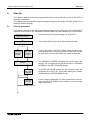
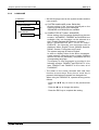
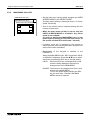
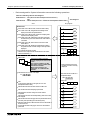
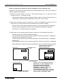
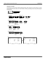
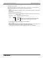
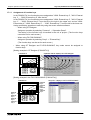
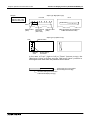
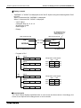
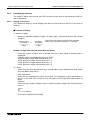
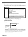
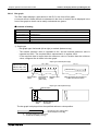
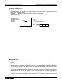
1.2.1
Contents described in manual
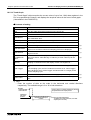
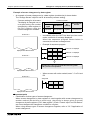
Introduction 1
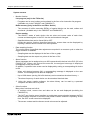
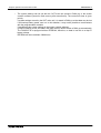
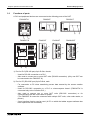
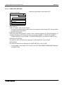
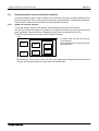
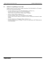
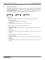
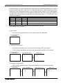
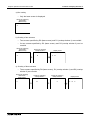
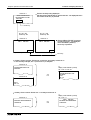
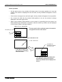
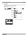
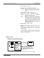
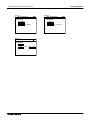
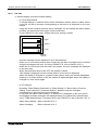
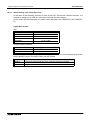
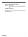
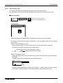
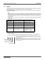
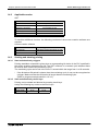
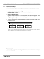
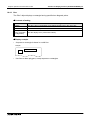
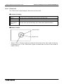
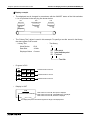
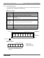
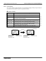
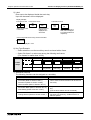
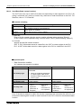
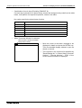
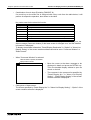
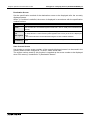
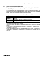
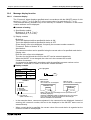
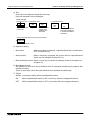
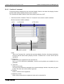
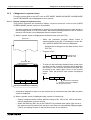
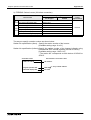
This manual is described in the following format. Use each element of the format for index.
Example:
Graphic Operation Terminal F940GOT
a)
2.
Startup
2.1
Startup procedure
Startup 2
b)
a) Chapter title
Chapter 1 to 16 describe operations.
Chapter 17 to 20 describe the contents
required to create screens.
b) Title
The title explains the contents of each
section.
2.1.1 GOT setup
c)
c) Sub title
d) Important point
Terms used in the text are explained and
supplemented.
d)
#Important point
MITSUBISHI
2-1
1-3
Graphic Operation Terminal GOT-F900
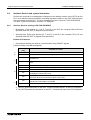
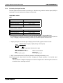
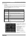
1.2.2
Introduction 1
Abbreviations used in text
The following terms may be abbreviated in the text.
1) MELSEC FX Series, A Series, QnA Series, Q Series programmable controllers and
programmable controllers by other companies may be abbreviated to "PLC".
2) The software kit to create display screens FX-PCS-DU/WIN-E or GT Designer may be
abbreviated to "screen creation software".
3) A general-purpose computer may be abbreviated to "PC".
4) A floppy disk may be abbreviated to "FD". A floppy disk drive may be abbreviated to "FDD".
5) The graphic operation terminal GOT-F900 Series may be abbreviated to "GOT".
6) Devices inside the PLC may be abbreviated to "X" (input), "Y" (output), "M" (auxiliary relay),
"S" (state), "T" (timer), "C" (counter) and "D" (data register). Output contacts of X,Y, M, S, T
and C are called "bit devices". T, C and D are called "word devices". All of them may be
called "devices".
1-4
Graphic Operation Terminal GOT-F900
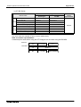
Introduction 1
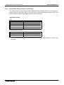
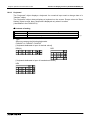
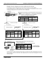
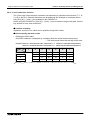
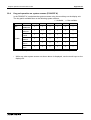
Abbreviation of model name
This manual describes the explanation related to the following products.
Each product is classified by the functions, and written as "F930GOT/F933GOT/F940GOT/
F943GOT/F940WGOT/handy GOT".
(The display unit in the handy GOT has the functions similar to those in the F940GOT or the
F943GOT. Unless otherwise specified, read the explanation of the F940GOT or the F943GOT
as the explanation of the handy GOT.)
Abbreviation
F920GOT-K
F930GOT-K
Model name F920GOT-BBD5-K-E F930GOT-BBD-K-E
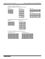
Abbreviation
Model name
F940GOT
F940GOT-SWD-E
F940GOT-LWD-E
F943GOT
F943GOT-LWD
F943GOT-SWD
F930GOT
F930GOT-BWD-E
F940WGOT
F940WGOT-TWD-E
F933GOT
F933GOT-BWD
Handy GOT
F940GOT-SBD-H-E
F940GOT-LBD-H-E
F943GOT-SBD-H-E
F943GOT-LBD-H-E
F940GOT-SBD-RH-E
F940GOT-LBD-RH-E
F943GOT-SBD-RH-E
F943GOT-LBD-RH-E
• "GOT with a key-pad" is the generic name for the F920GOT-BBD5-K-E and F930GOT-BBDK-E display units.
• The display unit in the F940GOT-LBD-H-E and the F940GOT-LBD-RH-E has the functions
similar to those in the F940GOT-LWD-E.
In this manual, the F940GOT-LBD-H-E and the F940GOT-LBD-RH-E are described as the
F940GOT or the F940GOT-LWD-E unless otherwise specified.
• The display unit in the F940GOT-SBD-H-E and the F940GOT-SBD-RH-E has the functions
similar to those in the F940GOT-SWD-E.
In this manual, the F940GOT-SBD-H-E and the F940GOT-SBD-RH-E are described as the
F940GOT or the F940GOT-SWD-E unless otherwise specified.
• The display unit in the F943GOT-LBD-H-E and the F943GOT-LBD-RH-E has the functions
similar to those in the F943GOT-LWD.
In this manual, the F943GOT-LBD-H-E and the F943GOT-LBD-RH-E are described as the
F943GOT or the F943GOT-LWD unless otherwise specified.
• The display unit in the F943GOT-SBD-H-E and the F943GOT-SBD-RH-E has the functions
similar to those in the F943GOT-SWD.
In this manual, the F943GOT-SBD-H-E and the F943GOT-SBD-RH-E are described as the
F943GOT or the F943GOT-SWD unless otherwise specified.
1-5
Graphic Operation Terminal GOT-F900
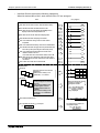
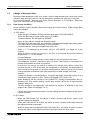
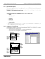
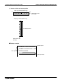
1.3
Introduction 1
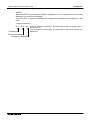
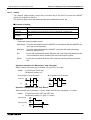
Expressions and basic functions of operation keys
The operation keys are expressed as follows in the text.
The examples of the screen display and key operation are described using the F940GOT if not
specified.
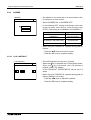
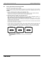
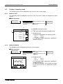
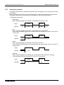
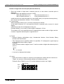
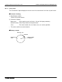
1.3.1
Expressions of operation keys
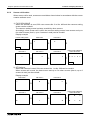
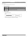
1) Touch keys on the screen which are actuated when being touched by fingers are enclosed
with a frame.
USER SCREEN MODE , PROGRAM LIST
2) Cursor control keys to be pressed may be expressed as follows.
,
,
3) When a same key is pressed several times or a same operation is repeated, the following
expression may be used.
, MORE
4) When an arbitrary numeric within the range of 0 to 9 is to be entered, the following
expression may be used.
0 to 9
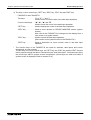
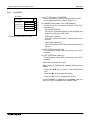
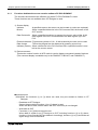
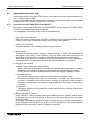
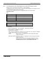
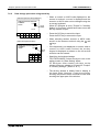
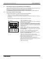
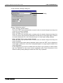
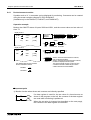
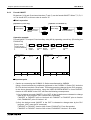
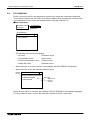
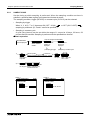
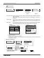
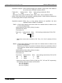
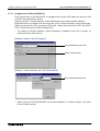
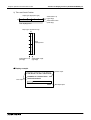
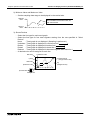
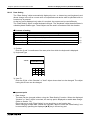
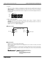
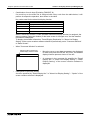
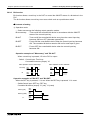
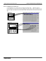
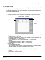
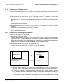
1.3.2
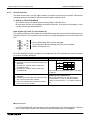
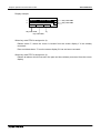
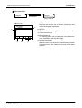
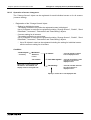
Basic operations
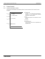
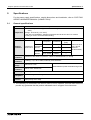
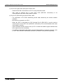
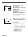
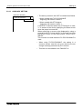
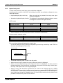
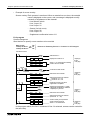
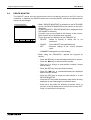
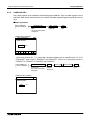
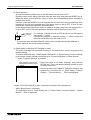
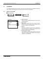
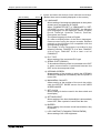
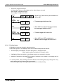
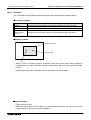
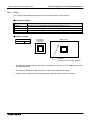
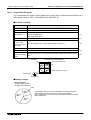
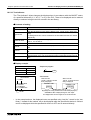
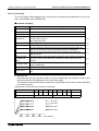
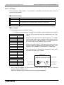
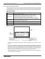
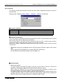
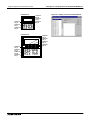
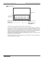
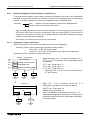
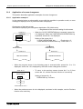
The common operations in the GOT are shown below.
a) Function display
The selected mode or function is displayed here.
b)
a)
[ SET CONDITION ]
END
b) END key
This key terminates the displayed function, and
returns to the previous screen.
SAMPLE COND.
START COND.
h)
END COND.
5
0
6
1
e)
7
2
8
3
c) CLR (clear) key
This key cancels the input of characters and
numeric values.
9
4
-
f)
CLR
ENT
g)
c)
d)
d) ENT (enter) key
This key determines the input of alphabets and
numerics.
e) Ten-key keypad
This keypad allows to enter numerics.
f) - (minus) key
g)
and
(cursor control) keys
h) Touch key for item setting
Displays a set item or keyboard for numeric input
in accordance with the contents of display.
1-6
Graphic Operation Terminal GOT-F900
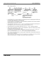
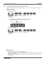
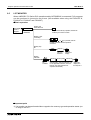
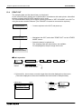
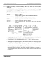
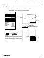
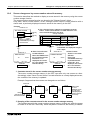
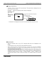
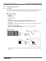
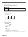
1.4
Introduction 1
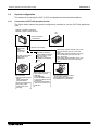
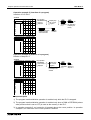
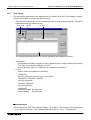
System configuration
The method of connecting the GOT to PLC and peripheral units is described below.
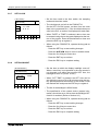
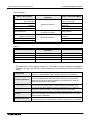
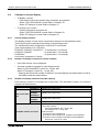
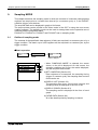
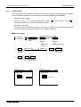
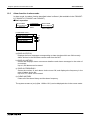
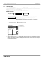
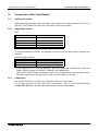
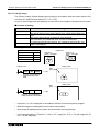
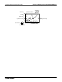
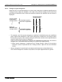
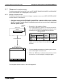
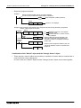
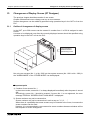
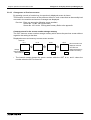
1.4.1
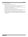
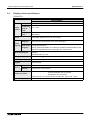
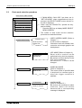
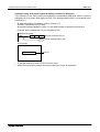
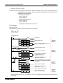
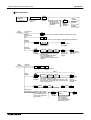
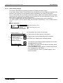
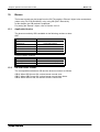
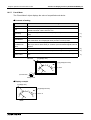
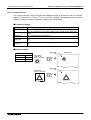
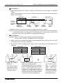
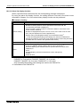
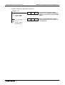
Connection of GOT with peripheral units
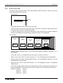
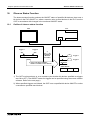
The figure below shows the system configuration required to use the GOT with peripheral
units.
F920GOT-K, F930GOT, F930GOT-K,
F933GOT, F940GOT, F943GOT and
F940WGOT graphic operation terminals
PLC
RS-422 or RS-232C
communication
Data transfer
cable
F2-232CAB-1
(3m (9' 10"))
RS-232C communication
RS-232C communication.
(Not available in the
F920GOT-K.)
·Printer
Bar code reader
<General-purpose printers>
ESC/P
Printer equipped with
RS-232C interface
Prints out sampling data,
alarm history, alarm
message and screen
hard copy
The ROM is attached to
F9GT-40UMB and inserted
into the connector on the
back of the GOT.
(F940GOT and F943GOT
only)
·EPROM memory
User screens can be stored
using a general-purpose
ROM writer.
(FX-EPROM-4M)
FX-PCS-DU/WIN-E is used
to put screen data in the form
of ROM chips.
(In the case of GT Designer,
data cannot be saved on to a
ROM chip.)
·Data transfer cable FX-232CAB-1 (3m (9' 10"))
(when the RS-232C port in the PC is 9-pin
type)
·Data transfer cable FX-232CAB-2 (3m (9' 10"))
(when the RS-232C port in the PC is halfpitch, 14-pin type)
·Data transfer cable F2-232CAB-1 (3m (9' 10"))
(when the RS-232C port in the PC is 25-pin
type)
·General-purpose personal computer
(screen creation software)
FX-PCS-DU/WIN-E or GT Designer
(Not available in the F920GOT-K.)
1-7
Graphic Operation Terminal GOT-F900
Introduction 1
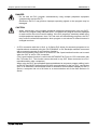
DANGER
• Do not edit the PLC program simultaneously using multiple peripheral equipment
(programming tool and GOT).
Otherwise, the PLC may produce improper operating signals or the program may be
damaged.
CAUTION
• When concurrently using multiple peripheral equipment (programming tool and GOT),
edit the PLC program using individual tools. The edited PLC program must be displayed
or read out from the unit unused for editing. If the PLC program is carelessly edited using
multiple peripheral equipment, thus, PLC and each unit has differing programs, the PLC
may execute unintended operations when program or set values for timer/counters is
changed next time.
• A CPU connection with the A, QnA, or Q Series PLC allows for sequence programs to be
transferred and monitored using the FX-PCS/WIN-E or GX Developer software connected
with a personal computer (2-port interface function).
When communicating with a QnA or Q series PLC the 2-port interface function can be used
when the GOT is set for CPU connection.
(The 2-port interface function is valid in the GOT920GOT-K-E only for CPU connection with
the FX Series PLC. This function cannot be used in any GOT when connected to a PLC
manufactured by other companies.)
When using the GOT and peripheral devices dedicated to sequence program editing (such
as FX-20P and A6GPP that performs RS-422 communication) for the one PLC, connect the
GOT to an extension communication board or extension communication adapter for the FX
Series, a computer link unit of A Series or a communication unit for the QnA Series or Q
Series.
1-8
Graphic Operation Terminal GOT-F900
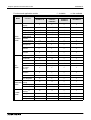
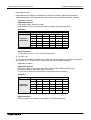
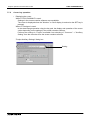
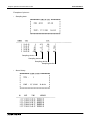
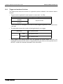
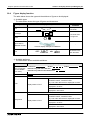
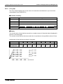
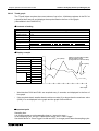
1.5
Introduction 1
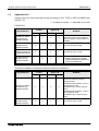
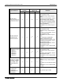
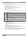
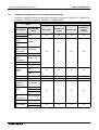
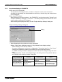
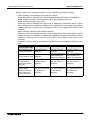
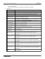
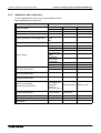
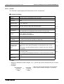
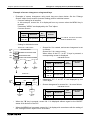
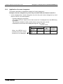
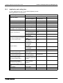
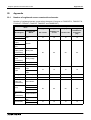
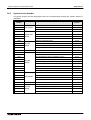
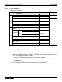
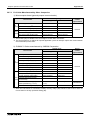
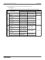
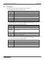
Applicable PLC
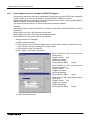
Setting of the PLC to be connected is made according to "PLC TYPE" in "SET-UP MODE (see
Section 7.2)".
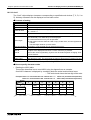
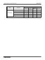
$: Possible to connect %: Impossible to connect
F920GOT-K
Applicable PLC
Direct connection
to CPU
RS-232C
RS-422
Computer link
Upper link
RS-232C
Remarks
RS-422
MELSEC FX Series
manufactured by
Mitsubishi Electric
%
$
%
%
Any version may be used.
Connection via function expansion
board for RS422 communication is
available.
MELSEC A Series
manufactured by
Mitsubishi Electric
%
$
%
%
Any version may be used.
MELSEC QnA
Series manufactured
by Mitsubishi Electric
%
$
%
%
Any version may be used.
%
Any version may be used.
• Including Q multi CPU system:
Q02CPU,Q02HCPU,Q06HCPU,
Q12HCPU,Q25HCPU
MELSEC Q Series
manufactured by
Mitsubishi Electric
$
%
%
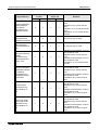
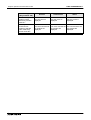
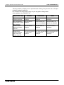
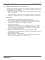
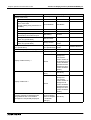
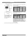
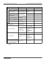
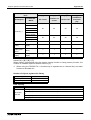
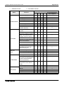
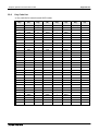
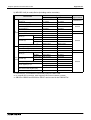
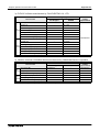
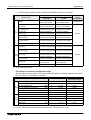
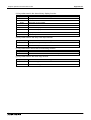
F930GOT-K/F930GOT/F933GOT/F940GOT/F943GOT/F940WGOT
Applicable PLC
Direct connection
to CPU
RS-232C
RS-422
Computer link
Upper link
RS-232C
Remarks
RS-422
MELSEC FX Series
manufactured by
Mitsubishi Electric
$*1
$
%
%
For connection to FX1S and FX1N
Series, the following versions
should be used.
F930GOT and F933GOT, V2.10 or
later should be used.
F930GOT-K any version may be
used.
F940GOT and F943GOT, V4.00 or
later should be used.
F940WGOT, any version may be
used.
MELSEC A Series
manufactured by
Mitsubishi Electric
%
$
$
$
Any version may be used.
1-9
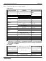
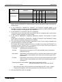
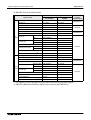
Graphic Operation Terminal GOT-F900
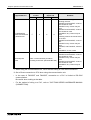
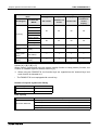
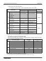
Applicable PLC
Direct connection
to CPU
RS-232C
MELSEC QnA
Series manufactured
by Mitsubishi Electric
MELSEC Q Series
manufactured by
Mitsubishi Electric
Q multi-CPU system
Q02CPU,
Q02HCPU,
Q06HCPU,
Q12HCPU,
Q25HCPU
Introduction 1
%
$
$
RS-422
$
%
%
Computer link
Upper link
RS-232C
$*2
$*2
$*2
Remarks
RS-422
$*2
F930GOT and F933GOT, V2.00 or
later should be used.
F930GOT-K any version may be
used.
F940GOT and F943GOT, V3.00 or
later should be used. (When a
version is former than V3.00 and
computer link connection is made,
only setting for computer link for A
Series is available.)
F940WGOT, any version may be
used.
$*2
F930GOT and F933GOT, V2.20 or
later should be used.
F930GOT-K any version may be
used.
F940GOT and F943GOT, V4.10 or
later should be used.
F940WGOT, any version may be
used.
For connection to Q00JCPU,
Q00CPU and Q01CPU the
following versions should be used.
F930GOT and F933GOT, V4.3 or
later should be used.
F940GOT and F943GOT, V6.3 or
later should be used.
F940WGOT, V1.30 or later should
be used.
$*2
F930GOT and F933GOT, V4.30 or
later should be used.
F930GOT-K any version may be
used.
F940GOT, and F943GOT, V6.30 or
later should be used.
F940WGOT, V1.30 or later should
be used.
MELSEC FX-10GM,
FX-20GM, E-20GM,
FX2N-10GM, FX2N20GM positioning
units
%
$
%
%
F930GOT, V4.10 or later should be
used.
F930GOT-K any version may be
used.
F940GOT, V6.10 or later should be
used.
F940WGOT, V1.10 or later should
be used.
Motion controllers
A171SCPU-S3,
A171SHCPU,
A172SHCPU and
A272UHCPU
%
$
%
%
Any version may be used.
1-10
Graphic Operation Terminal GOT-F900
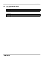
Applicable PLC
Introduction 1
Direct connection
to CPU
RS-232C
RS-422
Computer link
Upper link
RS-232C
Remarks
RS-422
Inverter FREQROLA500, E500 and
S500 Series
manufactured by
Mitsubishi Electric
%
$
%
%
F930GOT, V4.10 or later should be
used.
F930GOT-K any version may be
used.
F940GOT, V6.10 or later should be
used.
F940WGOT, V1.10 or later should
be used.
SYSMAC C Series
manufactured by
OMRON Corporation
%
%
$
$
Any version may be used.
FLEX-PC N Series
manufactured by
FUJI ELECTRIC CO.,
LTD.
%
%
$
$
Any version may be used.
%
F930GOT and F933GOT, V4.10 or
later should be used.
F930GOT-K any version may be
used.
F940GOT and F943GOT, V6.10 or
later should be used.
F940WGOT, V1.10 or later should
be used.
%
F930GOT and F933GOT, V3.00 or
later should be used.
F930GOT-K any version may be
used.
F940GOT and F943GOT, V5.00 or
later should be used.
F940WGOT, any version may be
used.
%
F930GOT and F933GOT, V2.00 or
later should be used.
F930GOT-K any version may be
used.
F940GOT and F943GOT, V5.00 or
later should be used.
F940WGOT, any version may be
used.
%
F930GOT and F933GOT, V4.00 or
later should be used.
F930GOT-K any version may be
used.
F940GOT and F943GOT, V5.00 or
later should be used.
F940WGOT, any version may be
used.
FP Series FP0 and
FP2SH
manufactured by
Matsushita Electric
Works, LTD.
Machine controllers
CP9200SH, MP920
and MP930
manufactured by
YASKAWA Electric
Corporation
SLC500 Series
manufactured by
Allen-Bradley Co.,
Inc.
MicroLogix 1000/
1200/1500 Series
manufactured by
Allen-Bradley Co.,
Inc.
$
$
$
$
%
$
%
%
%
%
%
%
1-11
Graphic Operation Terminal GOT-F900
Applicable PLC
Direct connection
to CPU
RS-232C
S7-200/300/400
Series manufactured
by Siemens AG
Microcomputer
board
Introduction 1
$
RS-422
%
Computer link
Upper link
RS-232C
%
Remarks
RS-422
%
The S7-300/400 is supported in the
following versions.
F930GOT and F933GOT, V3.00 or
later should be used.
F930GOT-K any version may be
used.
F940GOT and F943GOT, V5.00 or
later should be used.
F940WGOT, any version may be
used.
Following versions should be used
for S7-200:
F930GOT and F933GOT, V4.30 or
later
F930GOT-K any version may be
used.
F940GOT, and F943GOT, V6.30 or
later
F940WGOT, V1.30 or later
When connecting two or more units
F930GOT and F933GOT, V3.00 or
later should be used.
F930GOT-K any version may be
Select a communication procedure
used.
according to the GOT (RS-232C/RS-422).
F940GOT and F943GOT, V5.00 or
later should be used.
F940WGOT, any version may be
used.
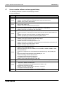
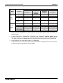
*1 When using the communication unit, use it with the setting of CPU direct connection.
*2 Set to Direct connection to CPU when using the communication unit.
• In the case of F933GOT and F943GOT, connection to a PLC is limited to RS-232C
communication.
Be careful when looking at the table.
• For the method of wiring to a PLC, refer to "GOT-F900 SERIES HARDWARE MANUAL
(CONNECTION).
1-12
Graphic Operation Terminal GOT-F900
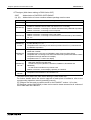
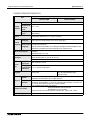
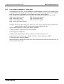
1.6
Introduction 1
GOT version upgrade history
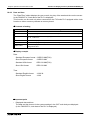
F920GOT-K
Version
V1.00
Description
•
First version
F930GOT-K
Version
V1.00
Description
•
First version
1-13
Graphic Operation Terminal GOT-F900
Introduction 1
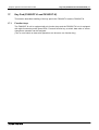
F930GOT and F933GOT
Version
Description
V1.00
•
First version
V2.00
•
•
•
•
•
•
Addition of function, connecting to QnA Series PLC
Addition of function, bar code connection
Addition of function, observe status
Touch key and lamp graphic extension
Compatible with SLC500 Series manufactured by Allen-Bradley Co., Inc.
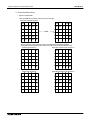
Addition of rectangle and circle daubing pattern
•
Addition of function, connecting to two or more units for microcomputer board
connection
V2.20
•
Addition of function, connecting to Q Series PLC
V3.00
•
•
Addition of function, connecting to S7-300/400 Series manufactured by Siemens AG
Addition of function, connecting to machine controller manufactured by YASKAWA
Electric Corporation
•
Addition of function, connecting to MicroLogix 1000/1200/1500 Series manufactured
by Allen-Bradley Co., Inc.
Addition of function, connecting to CS1 Series (CS1G/H-CPU!!-V1) manufactured
by OMRON Corporation
(Connection condition: Link connection)
Addition of function, entering numeric values including decimal points
Addition of security function (screen protection)
V2.10
•
V4.00
•
•
•
•
•
V4.20
•
•
•
•
•
•
•
V4.30
•
•
V4.40
V4.50
Addition of function, connecting to MELSEC positioning units FX-10/20GM, FX2N-10/
20GM, E-20GM
Addition of function, connecting to inverter FREQROL-A500, E500 and S500 Series
Addition of function, connecting to FP0 and FP2SH Series manufactured by
Matsushita Electric Works, LTD.
Addition of function, connecting to S7-200 Series manufactured by Siemens AG
Addition of function, displaying alarms in alarm list in order of occurrence
Addition of function, high-definition font display
Addition of function, "6dots × 8dots" font display
Coping with customizing of key window
Addition of function, connecting to Q00JCPU, Q00CPU and Q01CPU
Addition of function, connecting to Q multi-CPU system (Q02CPU, Q02HCPU,
Q06HCPU, Q12HCPU and Q25HCPU)
Addition of function, uploading recipe data by screen creation software
Addition of function, vertical display capability
•
•
Addition of function, buzzer sounds by GOT bit device (GB)
Change in ON/OFF process for bit devices, when connecting to PLCs manufactured
by Omron Corporation
•
•
The key code (FFFE) to mute the buzzer sound of touch keys is added.
Communication commands available while the microcomputer board is connected are
added:
Command to write two or more points in the unit of bit
Command to fill the internal data (D, M)
1-14
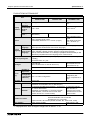
Graphic Operation Terminal GOT-F900
Introduction 1
F940GOT and F943GOT (including Handy GOT)
Version
Description
V1.00
•
First version
V1.10
•
•
Compatible with QnA Series (A Series mode)
Compatible with GT Designer.
V2.00
•
•
Compatible with SLC500 Series manufactured by Allen-Bradley Co., Inc.
Addition of function of bar code connection
V3.00
•
•
•
•
Addition of function, connecting to QnA Series PLC
Addition of hard-copy function
Addition of setting of key window initial display position
Addition of key code for alarm history
V3.10
•
•
•
•
Addition of observe status function
Compatible with customizing of key window
Touch key and lamp graphic extension
Addition of rectangle and circle daubing pattern
V4.00
•
Addition of function, connecting to FX1S and FX1N Series PLC
V4.10
•
Addition of function, connecting to Q Series PLC
V5.00
•
•
Addition of function, connecting to S7-300/400 Series manufactured by Siemens AG
Addition of function, connecting to machine controller manufactured by YASKAWA
Electric Corporation
•
Addition of function, connecting to MicroLogix 1000/1200/1500 Series manufactured
by Allen-Bradley Co., Inc.
Addition of function, connecting to CS1 Series (CS1G/H-CPU!!-V1) manufactured
by OMRON Corporation
(Connection condition: Link connection)
Addition of function, entering numeric values including decimal points
Addition of security function (screen protection)
•
V6.00
•
•
•
•
•
V6.20
•
•
•
•
•
•
V6.30
•
•
•
V6.40
V6.50
Addition of function, connecting to MELSEC positioning units FX-10/20GM, FX2N-10/
20GM, E-20GM
Addition of function, connecting to inverter FREQROL-A500, E500 and S500 Series
Addition of function, connecting to FP0 and FP2SH Series manufactured by
Matsushita Electric Works
Addition of function, connecting to S7-200 Series manufactured by Siemens AG
Addition of function, displaying alarms in alarm list in order of occurrence
Addition of function, high-definition font display
Addition of function, "6dots × 8dots" font display
Addition of function, connecting to Q00JCPU, Q00CPU and Q01CPU
Addition of function, connecting to Q multi-CPU system (Q02CPU, Q02HCPU,
Q06HCPU, Q12HCPU and Q25HCPU)
Addition of function, uploading recipe data by screen creation software
Addition of instructions, in HPP mode (FNC156 ABS, FNC169 HOUR, FNC176 RD3A,
FNC177 WR3A and FNC180 EXTR)
Addition of FX2N-8AD and FX2N-2LC buffer memory access
•
•
Addition of function, buzzer sounds by GOT bit device (GB)
Change in ON/OFF process for bit devices, when connecting to PLCs manufactured
by OMRON Corporation
•
•
The key code (FFFE) to mute the buzzer sound of touch keys is added.
Communication commands available while the microcomputer board is connected are
added:
Command to write two or more points in the unit of bit
Command to fill the internal data (D, M)
1-15
Graphic Operation Terminal GOT-F900
Introduction 1
F940WGOT
Version
V1.00
V1.10
Description
•
First version
•
Addition of function, connecting to MELSEC positioning units FX-10/20GM, FX2N-10/
20GM, E-20GM
Addition of function, connecting to inverter FREQROL-A500, E500 and S500 Series
Addition of function, connecting to FP0 and FP2SH Series manufactured by
Matsushita Electric Works
Addition of function, displaying alarms in alarm list in order of occurrence
Addition of function, high-definition font display
Addition of function, "6dots × 8dots" font display
•
•
•
•
•
•
•
V1.30
•
•
•
•
V1.40
V1.50
Addition of function, connecting to Q00JCPU, Q00CPU and Q01CPU
Addition of function, connecting to Q multi-CPU system (Q02CPU, Q02HCPU,
Q06HCPU, Q12HCPU and Q25HCPU)
Addition of function, connecting to S7-200 Series manufactured by Siemens AG
Addition of function, uploading recipe data by screen creation software
Addition of instructions, in HPP mode (FNC156 ABS, FNC169 HOUR, FNC176 RD3A,
FNC177 WR3A and FNC180 EXTR)
Addition of FX2N-8AD and FX2N-2LC buffer memory access
•
•
Addition of function, buzzer sounds by GOT bit device (GB)
Change in ON/OFF process for bit devices, when connecting to PLCs manufactured
by OMRON Corporation
•
•
The key code (FFFE) to mute the buzzer sound of touch keys is added.
Communication commands available while the microcomputer board is connected are
added:
Command to write two or more points in the unit of bit
Command to fill the internal data (D, M)
1-16
Graphic Operation Terminal GOT-F900
1.7
Introduction 1
Screen creation software version upgrade history
The following software is used to create display screens.
FX-PCS-DU/WIN-E
Version
Description
V1.00
•
First version (not compatible with F900 Series GOT)
V2.00
•
•
•
Addition of function, programming F940GOT
Addition of setting, display of line graph (batch) object and outer frame
Addition of key code for alarm history
•
•
Compatible with label color inversion of lamp (label) and touch key on black-and-white
liquid crystal display unit
Addition of function, programming Handy GOT
•
•
•
Addition of function, programming F930GOT and F933GOT display unit
Improving of graphic size (320 × 240 dots) registered in image library
Addition of function, connecting to bar code reader
•
•
•
•
Addition of function, connecting to QnA Series PLC
Addition of function, connecting to SLC500 Series manufactured by Allen-Bradley Co.,
Inc.
Addition of function, hard-copy setting on F940GOT display screen
Addition of graphic type to touch key and lamp (label) object
•
•
•
•
•
•
•
Addition of hatching pattern of rectangle and circle object
Addition of line type, straight line and rectangle object
Compatible with European font display
Addition of function, connecting to Q Series PLC
Addition of function, connecting to S7-300/400 Series manufactured by Siemens AG
Addition of alarm list and alarm history object
Addition of display, alarm mode flow
•
•
•
•
•
•
Addition of function, programming F940WGOT display unit.
Addition of PLC applicable to GOT
MELSEC positioning unit FX-10/20GM, FX2N-10/20GM, E-20GM, FREQROL A500,
E500, S500 Series
Extension of support device of SLC500 Series manufactured by Allen-Bradley Co.,
Inc.
MicroLogix Series manufactured by Allen-Bradley Co., Inc.
Addition of setting, observe status function
Compatible with high-definition font display
Compatible with "6 × 8 dots" font display
Addition of GOT-F900 internal device (GB, GD)
•
Addition of function of connecting to S7-200 Series manufactured by Siemens AG
•
•
•
•
Addition of PLC applicable to GOT
Q00JCPU, Q00CPU and Q01CPU
FP Series manufactured by Matsushita Electric Works, LTD.
Improvement of security function
Addition of function, vertical display capability in F930GOT
Compatible with Windows (R) Me
•
Compatible with F920GOT-BBD5-K and F930GOT-BBD-K
V2.10
V2.20
V2.30
V2.41
V2.50
V2.52
V2.60
V2.70
1-17
Graphic Operation Terminal GOT-F900
Introduction 1
GT Designer (Main items relating to F900 Series GOT)
SW!
: Abbreviation of SW!D5C-GOTR-PACKE
(A), (B)... : Abbreviation of screen creation software package version name
Version
Description
SW0D5C(A) •
•
SW1D5C(E)
•
•
First version (not compatible with F900 Series GOT)
Usable for F940GOT
(Usable for F940GOT whose main unit version is V1.10 or later)
Addition of function, connecting to C Series manufactured by OMRON Corporation
Addition of function, connecting to microcomputer
•
•
SW1D5C(H)
•
Usable for F930GOT and F933GOT
Addition of function, connecting to bar code reader
Addition of function, connecting to SLC500 Series manufactured by Allen-Bradley
Co., Inc.
SW2D5C(A) •
Addition of hard-copy function
•
SW5D5C(F)
V5.05F
•
Compatible with connecting to MicroLogix 1000/1200/1500 Series manufactured
by Allen-Bradley Co., Inc.
Compatible with connecting to CS1 Series (CS1G/H-CPU!!-V1) manufactured
by OMRON Corporation
•
SW5D5C(K) •
V5.09K
•
•
•
•
•
Addition of PLC applicable to GOT
Q00JCPU, Q00CPU and Q01CPU
Q multi-CPU system (Q02CPU, Q02HCPU, Q06HCPU, Q12HCPU and
Q25HCPU)
S7-200 Series manufactured by Siemens AG
Addition of function, vertical display capability in F930GOT
•
Compatible with F920GOT-K and F930GOT-K
SW5D5C(P)
V5.13P
SW5D5C
V5.26C
Compatible with connecting to MELSEC positioning units FX-10/ 20GM, FX2N-10/
20GM and E-20GM
Compatible with connecting to FREQROL A500, E500 and S500 Series
Compatible with connecting to FP Series manufactured by Matsushita Electric Works
Compatible with high-definition font display
Compatible with "6 × 8 dots" font display
• The items shown above are main items relating to F900 Series GOT.
For further details about the version upgrade of each piece of software, refer to the
corresponding operation manual (operating manual).
GT Designer can be used to create screens for the F940GOT version 1.10 or later.
GT Designer version SW1D5C(A) or later can be used to create screens for all versions of
GOTs other than the F940GOT.
1-18
Graphic Operation Terminal GOT-F900
1.8
Introduction 1
Preservation of screen data and backup
The undermentioned data is stored in RAM of GOT or the flash memory.
RAM area:
Data is backed up with the built in battery. (The F920GOT-K is equipped with the EEPROM.)
1) System settings, recipe (recipe data), and current time set by GOT main unit are stored in
RAM (a) below
2) Alarm data and sampling data are stored in RAM (b) below
Flash memory area: Battery is unnecessary.
3) Data made with screen creation software
Screen data, recipe (recipe data, recipe conditions), alarm conditions, sampling conditions
and system settings
GOT
Screen creation software
RAM(b)
RAM(a)
1)
Read
2)
The contents of RAM (a)
is updated when screen
data is transferred from
personal computer to
GOT.
. Recipe
. Alarm conditions
. Sampling conditions
. System settings
Personal
computer
Flash memory
Transfer
3)
Recipe is read from RAM (a) (conditions depend on the version).
• Transfer between the screen creation software and GOT is done between RAM (b) (except
current time) or flash memory.
When screen data is read from the GOT versions listed below to a personal computer,
screen data, alarm conditions, sampling conditions, and system settings are read from the
flash memory while recipe data is read from RAM (a).
(In earlier GOT versions, recipe data is stored to/read from the flash memory.)
F920GOT-K, F930GOT-K : First product
F930GOT, F933GOT
: V4.30 or later
F940GOT, F943GOT
: V6.30 or later
F940WGOT
: V1.30 or later
1-19
Graphic Operation Terminal GOT-F900
Introduction 1
• The system settings can be set with the GOT main unit (stored in RAM (a)) or the screen
creation software (stored in flash memory after transferred). The content set later is given
priority.
If system settings are set by the GOT main unit, it is stored in RAM (a) so that data may be lost
if the backup battery power runs out. In this situation, it may not be possible to communicate
with the programmable controller.
If possible set the system settings in the screen creation software.
(If data in RAM (a) is lost, the data in the flash memory will be written to RAM (a) automatically)
The F920GOT-K is equipped with an EEPROM, therefore, no data is lost due to a drop in
battery voltage.
EEPROM can be overwritten 10000 times.
1-20
Graphic Operation Terminal GOT-F900
2.
Specifications 2
Specifications
For the power supply specifications, outside dimensions and installation, refer to "GOT-F900
SERIES HARDWARE MANUAL (CONNECTION)".
2.1
General specifications
Item
Specifications
Use: 0 to 50°C (32 to 122°F) (0 to 40°C when using an extension interface or for Handy
GOT)
Temperature Storage: -20 to 60°C (-4 to 140°F)
In the case of F940WGOT, ambient temperature should be 0 to 50°C for vertical
mounting; 0 to 40°C for horizontal mounting.
Humidity
Use: 35 to 85%RH (non-condensing)
Frequency
Vibration
resistance
With
10 to 57Hz
Conforms to intermittent
57 to 150Hz
IEC 61131-2 vibration
With
10 to 57Hz
continuous
57 to 150Hz
vibration
Acceleration
Amplitude
(half)
0.075mm
9.8m/s2
0.035mm
4.9m/s2
10 times in each
of X, Y and Z
directions
(for 80 minutes)
Shock
resistance
Conforms to IEC 61131-2 (147m/s2, 3 times in each direction X, Y and Z)
Noise
resistance
1,000Vp-p, 1µs, 30 to 100Hz, tested by noise simulator.
Withstand
voltage
500V AC for 1 min
Insulation
resistance
5MΩ or more at 500V DC
Grounding
Class D (100Ω or less)
Working
atmosphere
No corrosive gas and no significant dust
Protective
structure
IP65f (Handy GOT: IP54) *1
Tested between power terminals and ground
*1 The relevancy is confirmed in the test for IP65f or IP54. However, this test result does not
provide any guarantee that the product withstands use in all types of environments.
2-1
Graphic Operation Terminal GOT-F900
2.2
Specifications 2
Display section specifications
F920GOT-K
Specifications
Item
Display
element
F920GOT-BBD5-K
LCD type
STN-type full dot matrix LCD
Dot pitch
Horizontal ×
Vertical
(mm)
0.47 × 0.47
Display
color
Monochrome
(Blue/White)
"128 × 64 dots" liquid crystal
Valid display dimension: 60 × 30 mm (3”-type)
Screen
System
language
Japanese and English (Japanese can be selected as system language only
while Japanese is selected as user screen language.)
Display
Japanese, English, Korean, Italian, Dutch, Swedish, Spanish, Danish, German,
language User screen Portuguese and French
Start up FX-PCS-DU/WIN-E or GT Designer (SW(D5C-GOTR-PACKE) on OS
language
(Windows) compatible with each language, then create screens.
Life of liquid crystal
Approximately 50,000 hours (Ordinary temperature: 25°C/77°F, Ordinary
humidity)
Guaranteed term is 1 year.
Backlight
LED
Touch key
No touch key
Key-pad
Ten-key keypad, cursor key, function keys (6), SET/DEV/ENT keys
26 keys in total
Interface
Color changeover (white/red) is available.
RS-422
In conformity with RS-422 standard, 1 channel and for PLC communication
RS-232C
In conformity with RS-232C standard, 1 channel and for screen data transfer or
Q Series PLC communication
Number of screens
User created screen: Max. 500 screens
FX-PCS-DU/WIN-E: No.0 to No.499
GT Designer: No.1 to No.500
System screen: 12 screens (Screen number: No. 1001 to No. 1030)
User memory
Flash memory 128KB
2-2
Graphic Operation Terminal GOT-F900
Specifications 2
F930GOT/F933GOT/F930GOT-K
Specifications
Item
Display
element
F930GOT-BWD
F933GOT-BWD
LCD type
STN-type full dot matrix LCD
Dot pitch
Horizontal ×
Vertical
(mm)
0.47 × 0.47
Display
color
Monochrome
(Blue/White)
F930GOT-BBD-K
"240 × 80 dots" liquid crystal
Valid display dimension: 117 × 42 mm (3”-type)
Screen
System
language
Japanese and English (Japanese can be selected as system language only
while Japanese is selected as user screen language.)
Display
Japanese, English, Korean, Italian, Dutch, Swedish, Spanish, Danish, German,
language User screen Portuguese and French
Start up FX-PCS-DU/WIN-E or GT Designer (SW(D5C-GOTR-PACKE) on OS
language
(Windows) compatible with each language, then create screens.
Life of liquid crystal
Approximately 50,000 hours (Ordinary temperature: 25°C/77°F, Ordinary
humidity)
Guaranteed term is 1 year.
Cold cathode
(life of 50,000 hours or more at 25°C/77°F)
Backlight
Guaranteed term is 1 year.
Touch
key
Number of
keys used
Max. 50 keys/1 screen
Configuratio
n (Horizontal "15 × 4" matrix configuration
× Vertical)
Key-pad
No key-pad
Ten-key keypad, cursor key, function
keys (6), SET/DEV/ENT keys
26 keys in total
RS-422
In conformity with RS-422 standard, 1 channel and for PLC communication
(F933GOT and F943GOT have no RS-422 port.)
RS-232C
In conformity with RS-232C standard, 1-channel and for screen data transfer.
(F933GOT and F943GOT: In conformity with RS-232C standard, 2 channel and
for screen data transfer and for PLC communication)
Interface
Number of screens
User created screen: Max. 500 screens
FX-PCS-DU/WIN-E: No.0 to No.499
GT Designer: No.1 to No.500
System screen: 25 screens (Screen number: No. 1001 to No. 1030)
User memory
Flash memory 256KB
2-3
Graphic Operation Terminal GOT-F900
Specifications 2
F940GOT/F943GOT/F940WGOT
Specifications
Item
Display
element
F940GOT-LWD
F943GOT-LWD
F940GOT-LWD
F943GOT-LWD
F940WGOT-TWD
LCD type
STN-type full dot matrix LCD
TFT-type full dot matrix
LCD
Dot pitch
Horizontal ×
Vertical
(mm)
0.36 × 0.36
0.324 × 0.375 *1
Display
color
Monochrome
(Blue/White)
8 colors
"240 × 80 dots" liquid crystal
Valid display dimension: 117 × 42 mm (3”-type)
Screen
System
language
256 colors
"480 × 234 dots" liquid
crystal
Valid display dimension:
115.5 × 87.8 mm (7”type)
Japanese and English (Japanese can be selected as system language only
while Japanese is selected as user screen language.)
Display
Japanese, English, Korean, Chinese (Simplified), Chinese (Traditional), Italian,
language User screen Dutch, Swedish, Spanish, Danish, German, Portuguese and French
Start up FX-PCS-DU/WIN-E or GT Designer (SW(D5C-GOTR-PACKE) on OS
language
(Windows) compatible with each language, then create screens.
Life of liquid crystal
Approximately 50,000 hours (Ordinary temperature: 25°C/77°F, Ordinary
humidity)
Guaranteed term is 1 year.
Cold cathode
(life of 40,000 hours or more at 25°C/77°F)
Backlight
Cold cathode
(life of 50,000 hours or
more at 25°C/77°F)
Guaranteed term is 1 year.
Number of
keys used
Touch
key
Max. 50 keys/1 screen
Configuratio
n (Horizontal "20 × 12" matrix configuration
× Vertical)
Key-pad
"30 × 12" matrix
configuration (last
column composed of 14
dots)
No key-pad
RS-422
In conformity with RS-422 standard, 1 channel and for PLC communication
(F933GOT and F943GOT have no RS-422 port.)
RS-232C
In conformity with RS-232C standard, 1-channel and
for screen data transfer.
(F933GOT and F943GOT: In conformity with RS232C standard, 2 channel and for screen data
transfer and for PLC communication)
Interface
Number of screens
In conformity with RS232C standard, 2channel and for screen
data transfer and for PLC
communication
User created screen: Max. 500 screens
FX-PCS-DU/WIN-E: No.0 to No.499
GT Designer: No.1 to No.500
System screen: 30 screens (Screen number: No. 1001 to No. 1030)
User memory
Flash memory 512KB
Flash memory 1KB
*1 Displayed items have a length to height ratio of about 1: 1.16.
2-4
Graphic Operation Terminal GOT-F900
3.
Name of Display Unit 3
Name of Display Unit
This section describes the name and the role of the display unit in the GOT.
For the operation switch and the grip switch in the handy GOT, refer to "GOT-F900 SERIES
HARDWARE MANUAL (CONNECTION)".
Front panel
1) Display
<Example>
- F920GOT-K
"128 × 64 dots" graphic display
F940GOT
Character string : 16 characters × 4 lines
The backlight changeover is available (white/red).
For settings, refer to Section 19.10 and 21.14.
- F930GOT, F933GOT, F930GOT-K (Horizontal display only)
"240 × 80 dots" graphic display
Character string :30 characters × 5 lines / Horizontal display
10 characters × 15 lines / Vertical display
- F940GOT, F943GOT
"320 × 240 dots" graphic display
Character string: 40 characters × 15 lines
- F940WGOT
F920GOT-K
"480 × 234 dots" graphic display
Character string:
60 characters × 14 lines / Horizontal display
29 characters × 30 lines / Vertical display
SET
!
DEV
1 )
P O W E R
2)
3)
ESC
!
- F920GOT-K ... Six membrane switches (without green
LED)
7 8 9
4 5 6
1 2 3
0 - ¥
!
2) Function keys
!
ENT
- F930GOT-K ... Eight membrane switches with green
LED
F930GOT-K
2)
8
9
4
1
5
2
6
3
0
-
¥
SET
!
DEV
ESC
!
7
!
• Using the screen creation software, set the operation of each
function key and alternate the status of each LED.
(Refer to Section 17)
!
3.1
ENT
3-1
3)
Graphic Operation Terminal GOT-F900
Name of Display Unit 3
3) Ten-keys, cursor control keys, "SET" key, "DEV" key, "ESC" key and "ENT" key
- F920GOT-K and F930GOT-K
Ten-keys . . . . . . . . . . . "0" to "9", "–" and "•"
Used to enter a numeric value in the data input operation.
Cursor control keys. . . """, "#", "!" and "$"
Used to move the cursor in the data input operation.
"SET" key . . . . . . . . . . Used to display the cursor in the data input operation.
"DEV" key . . . . . . . . . . Used to enter devices on DEVICE MONITOR screen (system
screen).
Also used in the F920GOT-K to change over the display from a
user screen to a system screen.
"ESC" key . . . . . . . . . . Used to cancel the data input operation.
(Also used to exit a system screen in the F920GOT-K.)
"ENT" key . . . . . . . . . . Used to determine an input numeric value in the data input
operation.
• The function keys in the F930GOT-K are used for switches, data inputs and screen
changeover on user screens.
The ten-keys, the cursor control keys, the "SET" key, the "ESC" key and the "ENT" key are
mainly used to change the data in "Numerical Input" and "Ascii Input". Set these keys using
the touch keys while a system screen is displayed. (Some keys are valid even while a
system screen is displayed. Refer to section 22.4.)
3-2
Graphic Operation Terminal GOT-F900
3.2
Name of Display Unit 3
Rear panel
F930GOT-K
F920GOT-K
5 )
C O M 1
R S 2 3 2 C
C O M 0
R S 4 2 2
1 )
2 )
F930GOT, F933GOT
F940WGOT
F940GOT, F943GOT
2 )
2 )
3 )
3 )
1 )
2 4 V D C
-
4 )
+
1 )
2 )
3 )
1) Power terminal
: Supply power to the GOT and for grounding.
The F920GOT-K 5V power is supplied from the PLC via cable.
2) Battery
: Store sampling data, alarm history and the current time.
Screen data is stored in the built-in flash memory, for which no
battery power is needed.
Battery name
F920GOT-K is not mounted with a battery.
F930GOT/F933GOT/F930GOT-K. . . FX2NC-32BL
F940GOT/F943GOT/F940WGOT . . . PM-20BL
3) Extension interface
: Connect optional extension devices.
A F9GT-40UMB type data transfer adapter is connected to
transfer screen data stored in the EPROM.
The F9GT-40UMB and F9GT-40FMB are applicable to the
F940GOT, F943GOT, and F940WGOT.
4) CN↔OP selector switch : Not used (F940GOT)
5) Name sheet
: The arbitrary key names can be assigned to the function keys of
the F930GOT-K.
An OHP transparent sheet is included with the product. Prepare
a name sheet referring the dimension indicated in the Installation
Manual offered with the product or Section 23.10 in this manual.
(The name sheet is not provided in the GOT units other than
F930GOT-K.)
3-3
Graphic Operation Terminal GOT-F900
3.3
Name of Display Unit 3
Functions of ports
A PLC and peripheral devices are connected to the following ports of the GOT.
F920GOT-K
F930GOT
1 )
F933GOT
2 )
3 )
1 )
2 )
F930GOT-K
F940GOT
4 )
F940WGOT
F943GOT
4 )
R S 2 3 2 C
R S 2 3 2 C
2 )
1 )
R S 2 3 2 C
R S 4 2 2
C O M 1
R S 2 3 2 C
4 )
3 )
1 )
3 )
C O M 0
R S 4 2 2
2 )
1 )
1) Port for PLC (RS-422 port) 9-pin D-Sub, female
- Used for RS-422 connection to a PLC.
- Also used to connect two or more GOT units (RS-422 connection). (Only one GOT can
be connected to the F920GOT-K.)
2) Port for PC (RS-232C port) 9-pin D-Sub, male
- For connection to PC when transferring screen data created by the screen creation
software.
- Used for RS-232C connection to a PLC or microcomputer board. (F920GOT-K is
connected only to the Q Series PLC.)
- Also used to connect two or more GOT units (RS-232C connection) or for
communication with bar code reader or printer.
(The F920GOT-K cannot be connected with multiple GOT units, a bar code reader, or
printer.)
- 2-port interface function can be used. (A PC on which the ladder support software has
been opened can be connected.)
3-4
Graphic Operation Terminal GOT-F900
Name of Display Unit 3
3) Port for PLC (RS-232C port) 9-pin D-Sub, male
- Used for RS-232C connection to a PLC or microcomputer board.
- Also used to connect two or more GOT units (RS-232C connection) or for
communication with a bar code reader or printer.
4) Port for PC (RS-232C port) 9-pin D-Sub, male
- For connection to PC when transferring screen data created by the screen creation
software.
- Not used for connection to a PLC.
- When the GOT is connected to a PLC through Port 3) (RS-232C), it can be used to
connect two or more GOT units (RS-232C connection) or for communication with a bar
code reader or printer.
- 2-port interface function can be used. (A PC on which the ladder support software has
been opened can be connected.)
- For details of connection with a PLC, microcomputer board, or personal computer, refer
to GOT-F900 SERIES HARDWARE MANUAL (CONNECTION) offered separately.
3-5
Graphic Operation Terminal GOT-F900
Name of Display Unit 3
MEMO
3-6
Graphic Operation Terminal GOT-F900
4.
Function
4.1
Function list
Function 4
The functions of the GOT are divided into 6 modes. The operator can use each function by
selecting the corresponding mode.
Mode
USER
SCREEN
MODE
HPP
MODE
Function
Reference
chapters
Outline of function
Character
display
• Alphanumerics are displayed.
Drawing
• Straight lines, circles and rectangles are displayed.
Lamp display
• The color of a specified area on the screen is inverted in
accordance with the ON/OFF status of the bit devices in
the PLC.
Graphic display
• Set values and current values of the word devices in the
PLC can be displayed in the form of bar graph, line graph
or panel meter.
Data display
• Set values and current values of the word devices in the
PLC can be displayed in the form of numeric.
Data change
function
• Current values and set values of the word devices are
the PLC can be changed.
7
19
21
• The ON/OFF status of bit devices in the PLC are
controlled.
Switch function
• Control can be in the format of momentary, alternate or
set/reset.
Screen
changeover
• The display screen can be changed over. The PLC or
touch key can be used to change over the display
screen.
Data batch
transfer
• Data saved in the GOT can be transferred to the PLC.
Security
function
• Screens are displayed only when the proper password is
entered. (This function is available also in the system
screens.)
Program (list) *1
• Programs can be read/written/monitored in instruction list
program format.
Parameter *1
• Parameters for the program capacity, memory latch
range, etc. can be read/written.
BFM monitor *1
• Buffer memories (BFM) in special blocks for the FX2N/
FX2NC Series can be monitored, and their set values
changed.
Device monitor
• The ON/OFF status of bit devices as well as current
values and set values of word devices can be monitored
using device numbers and comment expression.
Current value/
set value
change
• Current values and set values of word devices can be
changed using device Nos. and comment expression.
5
8
4-1
Graphic Operation Terminal GOT-F900
Mode
HPP
MODE
Function
Function 4
Reference
chapters
Outline of function
Forced
ON/OFF
• The bit devices in the PLC can be forced ON or OFF.
State monitor *1
• State (S) numbers in the ON status are automatically
displayed for monitoring (valid only when MELSEC FX
Series is connected).
8
PLC diagnosis *1 • Error information in the PLC is read and displayed.
Condition
SAMPLING setting
Result display
MODE
ALARM
MODE
TEST
MODE
• Conditions of up to four devices to be sampled, sampling
start/end time, etc. are set.
• The sampling result is displayed in the form of list or graph.
Data clear
• The sampling data is cleared.
List (status
display)
• The current alarms are displayed in the list in order of
occurrence.
History
• The alarm history is stored together with the event time,
in order of occurrence.
Frequency
• The number of events of each alarm is stored.
History clear
• The alarm history is deleted.
Screen list
• User screens are displayed in order of screen number.
Data file
• The data used in the recipe function (data file transfer
function) is changed.
Debug
operation
• The operations are checked to know whether key
operations, screen changeover, etc. have been correctly
performed on the displayed user screen.
9
10
11
Communication • The status of communication with the connected PLC is
monitor
displayed.
OTHER
MODE
Time switch
• A specified bit device is turned ON/OFF at specified time.
PC transfer
• The screen data, the data sampling result and the alarm
history can be transferred between the GOT and the
screen creation software.
Printer output
• The sampling result and the alarm history can be output
to a printer.
Entry code
• The entry code to protect programs in the PLC can be
registered.
System setting
• The initial setting can be specified for the system
language, connected PLC, serial transfer, title screen,
menu screen call, current time, backlight extinguishing
time, buzzer volume, LCD contrast, screen data clear, etc.
*1 Only valid when connecting to the FX Series PLC.
4-2
12
Graphic Operation Terminal GOT-F900
Function 4
$: Available
Functions and applicable models
%: Not available
Model name
F920GOT-K
F930GOT-K
F930GOT
F933GOT
F940GOT
F943GOT
F940WGOT
Character
display
$
$
$
$
Drawing
$
$
$
$
$
$
$
$
$
$
$
$
$
$
$
$
Data change
function
$*1
$*1
$
$
Switch function
$*1
$*1
$
$
Screen
changeover
$*1
$*1
$
$
Data batch
transfer
$*1
$*1
$
$
Security
function
$
$
$
$
Program (list)
%
%
$
$
Parameter
%
%
$
$
BFM monitor
%
$
%
$
$
$
$
$
Current value/
set value
change
$
$
$
$
Forced
ON/OFF
$
$
$
$
State monitor
%
$
$
$
PLC diagnosis
%
$
$
$
Condition
SAMPLING setting
Result display
MODE
%
%
$
$
%
%
%
%
$
$
$
$
%
%
$
$
%
%
%
%
%
%
$
$
$
$
$
$
Mode
Function
Lamp display
Graphic display
Data display
USER
SCREEN
MODE
Device monitor
HPP
MODE
Data clear
List (status
display) *2
ALARM
MODE
History *2
Frequency
History clear
4-3
Graphic Operation Terminal GOT-F900
Function 4
Model name
Mode
F920GOT-K
F930GOT-K
F930GOT
F933GOT
F940GOT
F943GOT
F940WGOT
$
$
$
$
$
$
$
$
Debug
operation
$
$
$
$
Communication
monitor
$
$
$
$
$*3
%
%
$
$
$
$
$
$
$
$
$
$
$
$
$
$
$
$
$
Function
Screen list
Data file
TEST
MODE
Time switch
OTHER
MODE
PC transfer
Printer output
Entry code
System setting
*1 When using the F920GOT-K, allocate each function to a function key.
When using the F930GOT-K, these functions can be allocated to either touch keys or
function keys.
*2 In the F920GOT-K, F930GOT-K, F930GOT, and F933GOT, ALARM MODE is not
available on system screens, but the similar display is available in USER SCREEN MODE.
The date and time is not displayed when using the Alarm list function in the F920GOT-K.
*3 In the F920GOT-K, clock data of the PLC is displayed.
This function can be used only when connected to the PLC equipped with a clock function
or either a memory cassette or memory board.
4-4
Graphic Operation Terminal GOT-F900
5.
Start Up 5
Start Up
This chapter describes the start up procedure from turning ON the power of the GOT to
selection of the mode.
This chapter also describes the important system settings to be used in the GOT. Make sure to
read this chapter carefully.
5.1
Start up procedure
This section describes the start up procedure from turning ON the power of the GOT to
selection of the mode. In the F940WGOT, BRIGHTNESS is used instead of LCD CONTRAST.
Perform wiring of the power
supply unit of the GOT.
Connect the PLC.
Turn on the
power without
pressing the
touch key.
Turn on the
power while
pressing the
touch key.
The OPENING SCREEN is
displayed.
• Perform wiring of the power supply unit of the GOT.
• Connect the GOT and the PLC with an optional cable.
• Turn on the power of the GOT. When turning on the power,
press and hold the top left hand corner of the GOT screen
for more than 1 second if the SET-UP screen is required.
• The OPENING SCREEN indicating the model name, the
version, etc. is displayed for the period set in "OPENING
SCREEN" in the SET-UP MODE screen.
The SET-UP
MODE screen
is displayed.
• In the SET-UP MODE screen, set the required mode, the
connected PLC name, etc. The system setting can also be
performed in the OTHER MODE screen.
A user screen
is displayed.
• A user screen is displayed. If a user screen does not exist,
then the SELECT MODE screen shown on the following
page is displayed.
When there is no screen data
5-1
Graphic Operation Terminal GOT-F900
The SELECT MODE screen is
displayed.
Start Up 5
2
• The SELECT MODE screen is displayed. Each menu
item on the screen functions as a touch key. When a
desired one is pressed, the corresponding mode is
selected.
* This SELECT MODE screen can be called also by
pressing a corner of the screen set in "MAIN MENU
CALL KEY" on the SET-UP MODE screen.
[ SELECT MODE ]
END
[ SELECT MODE ]
USER SCREEN MODE
HPP MODE
SAMPLING MODE
ALARM MODE
TEST MODE
OTHER MODE
The selected mode screen is
displayed.
• The selected mode screen is displayed.
2
USER SCREEN MODE is
displayed.
• If the menu call key is not set in "MAIN MENU CALL
KEY" on the SET-UP MODE screen, the USER
SCREEN MODE is displayed.
5-2
Graphic Operation Terminal GOT-F900
Start Up 5
5.2
System settings
5.2.1
Outline of operation environment setting
The system settings function configures the operation of the GOT. The SETUP MODE screen
can be displayed by turning on the power while pressing and holding the upper left corner of
the screen in accordance with the start-up procedure previously shown or by selecting OTHER
MODE on the SELECT MODE screen.
If an entry code has been registered using the security function (to protect screens), the
system settings can be set only when an entry code input by the user is equivalent to the
registered entry code.
[SET-UP MODE MENU SCREEN]
Turn on the power while pressing
and holding the upper left corner of
the screen.
Set the system language.
Press the END key.
The SET-UP MODE screen is
displayed.
[SET-UP MODE]
a)
LANGUAGE
b)
PLC TYPE
c)
SERIAL PORT (RS232C)
d)
OPENNING SCREEN
e)
MAIN MENU CALL
f)
SET CLOCK
g)
SET BACKLIGHT
h)
BUZZER
i)
LCD CONTRAST
j)
CLEAR USER DATA
k)
HANDY GOT SETTING
l)
AUXILIARY SETTING
END
m)
n)
Not available in the
F920GOT-K-E
n)
Only in Handy GOT
Not available in the
F920GOT-K-E
The areas enclosed with broken lines function as touch keys. (In the case of the F920GOT-K,
operate the key-pad.)
a) LANGUAGE
Allows setting of the language displayed on the system screens such as Japanese or
English.
When "CHARACTER SET" in "LANGUAGE" in "SET-UP MODE" is set to "WEST
EUROPE", the following nine languages can be displayed: Italian, English, Dutch, Swedish,
Spanish, Danish, German, Portuguese and French.
The system language is fixed to English.
In order to display either of the above languages, create screens using the screen creation
software opened on the OS (Windows) compatible with the corresponding language.
The display of nine languages is provided in the following versions: F930GOT and
F933GOT 2.10 or later, F940GOT and F943GOT 4.00 or later, F920GOT-K, F930GOT-K
and F940WGOT.
b) PLC TYPE
Allows setting of the connected PLC type
c) SERIAL PORT (RS232C)
To be selected when a printer is connected to the GOT or when communication is
performed between the GOT and a microcomputer board.
d) OPENING SCREEN
Allows setting of the duration in which the OPENING SCREEN is displayed immediately
after the power is turned ON.
5-3
Graphic Operation Terminal GOT-F900
Start Up 5
e) MAIN MENU CALL KEY
Allows setting of the position of the touch key which calls the SELECT MODE screen
from the USER SCREEN MODE
f) SET CLOCK
Allows setting of the time used in the time switch and time display
g) SET BACKLIGHT
Allows setting of the time the backlight is automatically turned OFF, after a period of
continuous idle time
h) BUZZER
Allows setting of the buzzer sound issued when a key is pressed
i) LCD CONTRAST (F940WGOT: BRIGHTNESS)
Allows setting of the LCD brightness
j) CLEAR USER DATA
Deletes all user screen data
k) HANDY GOT SETTING
Allows setting of the grip switch or LED (Only in Handy GOT)
l) AUXILIARY SETTING
Choose "WRITE" or "DOES NOT WRITE" for the initial display screen number to a PLC
m) END
Exits the SET-UP MODE screen. SELECT MODE is displayed.
n) Cursors
Change over the menu item on the SET-UP MODE screen
#Important point
• When the items a) to e), g), h), k) and n) above are set in the GOT and screen data is
transferred from the screen creation software, the system settings selected in the screen
creation software becomes valid. In such a case, set the system settings in the GOT again
or align from the beginning the setting of the items a) to e), g) and h) above with that in the
screen creation software.
• A system setting with the GOT main unit is stored in RAM. (Refer to Section 1.8)
(When using the F920GOT-K, settings are stored in the EEPROM.)
5-4
Graphic Operation Terminal GOT-F900
5.2.2
Start Up 5
LANGUAGE
• Set the language used on the system screens and the
user screens.
[ LANGUAGE ]
[ LANGUAGE ]
END
SYSTEM LANGUAGE:
ENGLISH
a)
CHARACTER SET:
JAPANESE
b)
a) SYSTEM LANGUAGE (Initial: ENGLISH)
Allows setting of the language displayed on the
system screens and in error messages
JAPANESE and ENGLISH are available.
b) CHARACTER SET (Initial: JAPANESE)
Allows setting of the language displayed on the user
screens. JAPANESE, CHINESE and KOREAN are
available. Only one language can be selected at a
time. English character set is always available.
When "CHARACTER SET" is set to "WEST
EUROPE", the following nine languages can be
displayed: Italian, English, Dutch, Swedish, Spanish,
Danish, German, Portuguese and French.
The system language is fixed to English.
In order to display either of the above languages,
create screens using the screen creation software
opened on the OS (Windows) compatible with the
corresponding language.
The display of nine languages is provided in the
following versions: F930GOT and F933GOT 2.10 or
later, F940GOT and F943GOT 4.00 or later, all of
F940WGOT.
• The areas on the screen enclosed with solid lines
function as touch keys. Every time a touch key is
pressed, the displayed contents are changed over.
When using the F920GOT-K, operate the key-pad as
follows:
- Press the !/$ key to move to the previous/next
item.
- Press the # key to change the setting.
- Press the ESC key to complete the setting.
5-5
Graphic Operation Terminal GOT-F900
5.2.3
Start Up 5
PLC TYPE
a) PLC TYPE (Initial: FX SERIES)
Allows selection of a PLC to connect with the GOT
For the applicable PLCs, refer to Section 1.5.
[ PLC TYPE ]
END
[ PLC TYPE ]
PLC TYPE:
FX SERIES
a)
CONNECTION:
CPU PORT(RS422)
b)
DST STATION #:
* *
c)
GOT STATION #:
* *
d)
• Select the connected PLC type.
b) CONNECTION (Initial: CPU PORT(RS422))
Allows to set the connection method of the PLC
selected in a).
- CPU PORT (RS422):
The GOT is connected directly to the program port
in the PLC (RS-422 or RS-232C).
- LINK PORT (RS422):
The GOT performs RS-422 communication via a
link unit.
- LINK PORT (RS232C):
The GOT performs RS-232C communication via a
link unit.
c) DST STATION # (Initial: 00)
The displayed words differ according to the GOT
versions.
d) GOT STATION # (Initial: 00)
The displayed words differ according to the GOT
versions.
• Select the connected PLC type.
When using the F920GOT-K, operate the key-pad as
follows:
- Press the !/$ key to move to the previous/next
item.
- Press the # key to change the setting.
- Press the ESC key to complete the setting.
In the F920GOT-K, station # is unavailable, and only
the CPU PORT is available for CONNECTION.
5-6
Graphic Operation Terminal GOT-F900
5.2.4
Start Up 5
SERIAL PORT
[ SERIAL PORT ]
END
[ SERIAL PORT ]
SPEED:
9600 bps
DATA BIT:
7 bit
STOP BIT:
1 bit
PARITY:
Even
HANDSHAKING:
XON/XOFF
PRINTER:
DON'T USE
• Set the serial communication parameters for the
printer used to print out alarm messages and sampling
data. (Initial: Left screen)
• Make sure to set "PRINTER" to "USE" when a printer
is connected.
When it is set to "USE", the two-port interface
function is not available.
• The area enclosed with broken lines function as touch
keys. Every time a touch key is pressed, the displayed
setting items change.
• When "LINK PORT (RS232C)" is selected on the PLC
TYPE screen, a printer cannot be connected.
• A bar code reader can be connected. However, if a
printer is connected, the computer link connection
cannot be performed (RS232C).
• This item is not available in the F920GOT-K.
5.2.5
OPENING SCREEN
[ OPENING SCREEN ]
END
[ OPENING SCREEN ]
DISPLAY TIME
5
6
7
8
9
0
1
2
3
4
4 SEC.
-
• Set the duration in units of seconds in which the
OPENING SCREEN indicating the model name, the
version, etc. is displayed immediately after the power
is turned on. (Initial: 4sec)
• When the touch key "DISPLAY TIME" is pressed, the
time can be set using the ten-key pad displayed at the
bottom of the screen.
CLR
ENT
• Enter the desired display time and press the ENT key
to register the input time.
* If "DISPLAY TIME" is set to "0", the USER
SCREEN MODE is displayed.
It is recommended to set 1 second or more for the
FX Series and 4 seconds or more for the A Series.
• When using the F920GOT-K, operate the key-pad as
follows:
- Press the SET key to start making changes.
- Press the 0 to 9 keys to enter time.
- Press the ENT key to set time.
- Press the ESC key to complete setting.
5-7
Graphic Operation Terminal GOT-F900
5.2.6
Start Up 5
MAIN MENU CALL KEY
[ MAIN MENU CALL KEY ]
[ MAIN MENU CALL KEY ]
END
SELECT CALL KEY LOCATION
• Set the main menu call key which changes over USER
SCREEN MODE to the SELECT MODE.
The main menu call key is mesh type, and 2 × 2 in size.
(Initial: On the left)
• One or two corners can be selected among the four
corners of the screen.
• When the main menu call key is not set, only the
USER SCREEN MODE is available. Any other
mode is not available.
(In order to display the MAIN MENU, turn on the
power again pressing the top left hand corner of
the screen and hold it for more than 1 second.)
• If another touch key is assigned to the corners to
which the main menu call key has been assigned, the
menu call function is disabled.
• Manipulation of the key-pad is required in the
F920GOT-K.
When the MAIN MENU CALL KEY is selected, VALID
or INVALID is displayed. Press the !/$ key to select
either one and press the ESC key to exit the setting.
VALID:
When the DEV key is pressed while a user
screen is being displayed, the screen is
changed over to the MAIN MENU.
INVALID: The screen is not changed over from a user
screen to the MAIN MENU.
Turn on the power again pressing the DEV
key for more than 1 second if the MAIN
MENU screen is required.
5-8
Graphic Operation Terminal GOT-F900
5.2.7
Start Up 5
SET CLOCK
[ SET CLOCK ]
END
[ SET CLOCK ]
DATE
3 / 1 / 1999
TIME
10: 10: 10
5
6
7
8
9
0
1
2
3
4
• Set the time used in the time switch, the sampling
mode and the alarm mode.
• The clock data is not built in the F920GOT-K.
On the SET CLOCK screen, set time from the clock
data in the connected PLC. If the clock data does not
exist in the PLC, a number 0 is displayed for each field.
-
CLR
ENT
• When "DATE" or "TIME" is selected, date or time can
be entered using the ten-key pad displayed at the bottom of the screen. Enter the desired date or time and
press the ENT key to register it.
• When using the F920GOT-K, operate the key-pad as
follows:
- Press the SET key to start making changes.
- Press the !/$/"/# keys to move to another items.
- Press the 0 to 9 keys to enter time.
- Press the ENT key to set time.
- Press the ESC key to complete setting.
5.2.8
SET BACKLIGHT
[ SET BACKLIGHT ]
END
[ SET BACKLIGHT ]
OFF TIME
10 MIN.
5
6
7
8
9
0
1
2
3
4
-
CLR
ENT
• Set the time at which the display backlight turns off.
When a touch key is not pressed or the user screen is
not changed over within the specified OFF time, the
backlight is turns off. (Initial: 10 min)
• When "OFF TIME" is pressed, the OFF time can be
set within the range of 0 to 99 minutes using the tenkey pad displayed at the bottom of the screen. Enter
the desired time and press the ENT key to register it.
• The life of the backlight is 25000 hours.
• The specified bit of the control device (system information) should be set to ON so that the backlight OFF
function is enabled. (Refer to Section 6.6.)
• When using the F920GOT-K, operate the key-pad as
follows:
- Press the SET key to start making changes.
- Press the 0 to 9 keys to enter time.
- Press the ENT key to set time.
- Press the ESC key to complete setting.
5-9
Graphic Operation Terminal GOT-F900
5.2.9
Start Up 5
BUZZER
[ BUZZER ]
END
[ BUZZER ]
• Set whether or not the buzzer is to sound when a key
is pressed or an error occurs.
• Select "BUZZER ON" or "BUZZER OFF".
• In the following GOT, muting of the buzzer sound can
be set for each touch key by using the key code
(FFFE) (This setting is unavailable in the F920GOT.).
BUZZER ON
BUZZER OFF
Model
Applicable version
F930GOT, F933GOT
V4.50 and later
F930GOT-K
From first product
F940GOT, F943GOT
(including ET and handy GOT)
V6.50 and later
F940WGOT
V1.50 and later
• When using the F920GOT-K, operate the key-pad as
follows:
- Press the !/$ keys to move the cursor.
- Press the ESC key to complete setting.
5.2.10
LCD CONTRAST
[ LCD CONTRAST ]
[ LCD CONTRAST ]
END
• The LCD brightness can be set in 15 steps.
When the
key is pressed, the LCD becomes darker.
When the
key is pressed, the LCD becomes
brighter. (Initial: The middle)
In the F940WGOT, "BRIGHTNESS" can be set in 4
steps.
• When using the F920GOT-K, operate the key-pad as
follows (Setting in ten scale):
- Press the "/# keys to adjust the contrast.
- Press the ESC key to complete setting.
5-10
Graphic Operation Terminal GOT-F900
5.2.11
Start Up 5
CLEAR USER DATA
• The screen data stored in the GOT can be cleared.
[ CLEAR USER DATA ]
[ CLEAR USER DATA ]
OK TO CLEAR USER DATA ?
YES
NO
END
• When "YES" is selected, the message "NOW
CLEARING USER DATA" is displayed and any key
operations are not accepted.
• After that, the USER SCREEN MODE is automatically
selected. The message "DISPLAY SCREEN IS NOT
AVAILABLE" on the screen indicates the data has
been cleared completely.
• When using the F920GOT-K, operate the key-pad as
follows:
- Press the "/# keys to adjust the contrast.
- Press the ENT key to execute.
- Press the ESC key to complete setting.
5-11
Graphic Operation Terminal GOT-F900
5.2.12
Start Up 5
HANDY GOT SETTING
Setting the grip switch of the Handy GOT
[ HANDY GOT SETTING ]
[ HANDY GOT SETTING ]
GRIP SWITCH:
END
DON'T USE
PUSH BUTTON WRITE:
DOES NOT WRITE
SWITCH OFF ACTION:
TOUCH SWITCH OFF
LED ACTION:
CONCURRENTLY WITH GRIP SWITCH
GRIP SWITCH
"USE" or "DON’T USE" can be chosen.
• If a screen is created whose version does not correspond to the Handy GOT, the grip switch
is always valid on the screen.
PUSH BUTTON WRITE
Select the grip switch ON/OFF status in the "Interface Devices (FX-PCS-DU/WIN-E)" or
"System Information (GT Designer)" menu by choosing "WRITE" or "DOES NOT WRITE".
• If "GRIP SWITCH" is set to "USE", "PUSH BUTTON WRITE" can be set to "WRITE" only.
SWITCH OFF ACTION
The SWITCH OFF ACTION can be selected if "GRIP SWITCH" is set to "USE".
LED ACTION
The LED ACTION can be selected if the "GRIP SWITCH" is set to "USE".
• For the details of the Handy GOT, refer to the GOT-F900 SERIES HARDWARE MANUAL
(CONNECTION).
5-12
Graphic Operation Terminal GOT-F900
5.2.13
Start Up 5
AUXILIARY SETTING
[ AUXILIARY SETTING ]
[ AUXILIARY SETTING ]
INIT SCREEN NO: WRITE
• The start-up screen in the GOT is numbered as follows.
END
- When created with FX-PCS-DU/WIN-E:
beginning with screen number 0
- When created with GT Designer:
beginning with screen number 1
If "WRITE" is selected when the GT Designer is used,
"1" is written to the device specifying the base screen
when the power is turned ON.
When specifying a screen to be displayed by using a
program in the PLC when the PLC is changed over from
the STOP status to the RUN status, select "NOT
WRITE".
This function is invalid when the FX-PCS-DU/WIN-E is
used.
• When using FX-PCS-DU/WIN-E, the setting in a
common screen must be set up so that the screen
change is always performed by PLC devices.
• This item is not available in the F920GOT-K.
5-13
Graphic Operation Terminal GOT-F900
5.3
Start Up 5
Each mode selection procedure
MODE SELECT MENU SCREEN
[ SELECT MODE ]
USER SCREEN MODE
HPP MODE
SAMPLING MODE
ALARM MODE
TEST MODE
OTHER MODE
END
• If "MAIN MENU CALL KEY" has been set in
"SET-UP MODE", when a specified touch key is
pressed, the SELECT MODE screen shown on
the left is displayed.
• When using the F920GOT-K, operate the keypad as follows:
- Press the DEV key to display MODE SELECT
MENU SCREEN.
• The outline of each mode and the selection
procedure are described below.
USER SCREEN MODE
Production control
Number of products
1234
Operation rate
HPP MODE
SUMPLING MODE
ALARM MODE
[ HPP MODE ]
END
PROGRAM LIST
PARAMETER
[ SUMPLING MODE ]
END
SET CONDITION
DISPLAY LIST
[ ALARM MODE ]
DISPLAY STATUS
DISPLAY HISTORY
END
• USER SCREEN MODE (Refer to
Chapter 7.)
A user screen is displayed.
Characters such as standard text,
numerics and simple graphic can
be displayed.
• HPP MODE (Refer to Chapter 8.)
Read, write or monitor can be
performed using the list programs.
Bit devices and word devices in the
PLC can be monitored.
Set values of T, C and D can be
changed.
• SAMPLING MODE
(Refer to Chapter 9.)
The current value of specified data
is acquired in a constant cycle or
when the trigger condition is
satisfied.
• ALARM MODE
(Refer to Chapter 10.)
Bit devices are monitored as alarm
elements. When a bit device
becomes ON, a corresponding
message is displayed.
5-14
Graphic Operation Terminal GOT-F900
TEST MODE
Start Up 5
[ TEST MODE ]
• TEST MODE (Refer to Chapter 11.)
The contents of the user screens can
be confirmed. In addition, data files
can be edited, and debugging can be
performed.
F 9 4 0 G O T,
F943GOT
and
F940WGOT can display the
communication.
END
• OTHER MODE
(Refer to Chapter 12.)
Setting of the time switch, printer
output, entry code, system, etc. can
be performed.
USER SCREEN
DATA BANK
[ OTHER MODE ]
OTHER MODE
END
SET TIME SWITCH
DATA TRANSFER
5-15
Graphic Operation Terminal GOT-F900
5.4
Start Up 5
Security function (screen protection function)
In the user screen mode, screens can be set so that they only open to certain operators who
know an entry code. This is so that general operators cannot perform unnecessary operations.
This function is called security function (screen protection function).
5.4.1
Outline of security function
To use the security function, the security level should be set for each user screen.
Set the level within the range of 0 (lowest) to 15 (highest). When any entry codes have not
been registered, all screens can be displayed (In this case, the security level is "0".).
An entry code can be set using the screen creation software.
GOT
Level 2
Screen
Screen
Level 1
Screen
Screen
Level 0
Screen
• An entry code can be set using up
to 8 numerics.
(Only numbers 0 to 9 can be used in
the F920GOT.)
Screen
By entering a correct entry code, the user can display and manipulate screens whose
security level is equivalent to or lower than the entered code
5-16
Graphic Operation Terminal GOT-F900
5.4.2
Start Up 5
Input of entry code
To enter code, the entry code input screen should be displayed.
According to the versions of the GOT, the following functions are available to display the entry
code input screen.
• Keyboard display by a touch key
: When a touch key is pressed, the entry code input
screen is displayed.
• Automatic keyboard display function: The keyboard is automatically displayed when a screen
is changed to a screen with higher security.
GOT version
Product model name
Keyboard display by touch key
Automatic keyboard display
V1.00
V4.00
F930GOT, F933GOT
F930GOT-K
From first product
F940GOT, F943GOT
V1.00
V6.00
F940WGOT
V1.00
V1.00
• On the F920GOT-K, entry code input window is displayed automatically.
Screen creation software version
Software name
GT Designer
FX-PCS-DU/WIN-E
Keyboard display by touch key
Automatic keyboard display
SW1D5C-GOTR-PACKE (C)
SW5D5C-GOTR-PACKE V5.05F
V2.00
−
Entry code input keyboard displayed by a touch key
In order to display the entry code input keyboard by a touch key, set the key code "FF68" to
the touch key arranged on the screen.
Screen example
Input of entry code
Touch key
• To set this touch key, enter "FF68" to the key code.
• When the touch key is pressed, the entry code input screen is displayed.
• When a screen whose security level is higher is tried to be displayed, an alarm sound is
issued three times. Set a touch key, and enter an entry code. Once an entry code is input,
the entry code input screen is no longer displayed.
• When an entry code has been registered to the screen to be displayed at first in USER
SCREEN MODE (screen No. 0 when screens have been created using FX-PCS-DU/WIN-E
or screen No. 1 when screens have been created using SW!D5C-GOTR-PACKE), the
entry code input screen is displayed even if a touch key to enter an entry code is not
provided so that an entry code can be entered.
5-17
Graphic Operation Terminal GOT-F900
Start Up 5
Automatic entry code input keyboard display function (GT Designer)
If the following is set, entry code input keyboard is automatically displayed when a screen is
changed over to a screen with higher security. (The setting shown below is not required in the
F920GOT-K.)
• System Information (For details, refer to Section 6.6.)
The b8 in read device (D&) is ON:
Automatic keyboard display is valid. & is the head number of specified read device.
Example: when read device (D&) is assigned to D10
M8000 (ON during RUN)
MOV K3M10 D10
M18
M10 to M21 is transferred to D10
Automatic keyboard display is valid.
Screen example
Input of entry code
Touch key
• To set this touch key, enter "FF68" to the key code.
• When the touch key is pressed, the entry code input screen is displayed.
5-18
Graphic Operation Terminal GOT-F900
5.4.3
Start Up 5
Reset of entry code
To reset an entry code and return to the initial setting (in which security is valid), a touch key
should be provided on the screen.
Screen example
Reset of entry code
Touch key
• To set this touch key, enter "FF69" to the key code.
• The entry code is reset also when the power of the GOT is turned off. When the power is
turned on at the next time, the security is valid.
• In order to reset the entry code in the F920GOT-K, press the ESC key and then 9 when the
screen is not waiting for numerical key-in (when the cursor is not displayed).
Use example
Level 4
Entry code
:444
Screen 5
Level 3
Entry code
:333
Screen 4
Level 2
Entry code
:222
Screen 3
Level 1
Entry code
:111
Screen 2
Level 0
Entry code
Nothing
Screen 1
• Suppose that the security level is set in the screen creation software for Screens 1 to 5
shown above.
• In this case, Screen 1 is displayed when the power is turned on (Level 0).
• When an entry code "222" is entered, Screens 1 to 3 can be displayed and manipulated.
• When an entry code "444" is entered while Screens 1 to 3 are displayed, Screens 1 to 5 can
be displayed and manipulated.
• When the entry code is reset while Screens 1 to 5 are displayed, Screen 1 is displayed
(initial status).
* In the use example shown above, the levels and the screen numbers are consecutive for
easy understanding. The levels and the screen numbers are not necessarily consecutive.
Example: Screen 1
Screen 2
Screen 3
Screen 10
: Level 3
: Level 7
: Level 5
: Level 2
5-19
Graphic Operation Terminal GOT-F900
5.4.4
Start Up 5
Upgrading of security function
The following functions have been added to the security function, making the system easier to
use.
Applicable version
GOT
Product model name
F930GOT, F933GOT
F920GOT-K, F930GOT-K
Version
V4.00
From first product
F940GOT, F943GOT
V6.00
F940WGOT
V1.00
Screen creation software
Software name
GT Designer
FX-PCS-DU/WIN-E
Applicable version
SW1D5C-GOTR-PACKE V5.05F
V2.00
5-20
Graphic Operation Terminal GOT-F900
Start Up 5
1) Function to display error messages at entry code input
Previously no error message was displayed at the time of incorrect entry code input or
switching to protected screens.
Now it is possible to produce an error display by setting it as shown below.
• Setting for GT-Designer (SW5D5C-GOTR-PACKE)
a) The following window can be displayed by using "Common" → "Password".
When it is checked, the level
device setting is enabled.
(See 2) in the next page.)
When it is checked, an error
message is displayed at the
time of incorrect entry code
input.
• Entry code input and contents of error message
Error message
Password is incorrect.
When the entered entry code is incorrect
(Enter the correct entry code.)
This operation is not permitted.
When switching to a high-security-level screen is
attempted
(It is necessary to enter the entry code.)
• Only numbers 0 to 9 can be used for an entry code in the F920GOT-K.
2) Level device setting function
By setting as shown below, the current security level (0 to 15) set on the GOT can be
checked through the PLC.
• Setting for GT-Designer (SW5D5C-GOTR-PACKE)
a) The window shown in the previous page can be displayed by using "Common" →
"Password".
b) When the "Level device" item is checked, device setting for security level can be made.
By checking the current set value of the device here, you know the current security level.
5-21
Graphic Operation Terminal GOT-F900
Start Up 5
3) Security level setting function for system screen
Previously the security level of the system screens (No.1000 to 1030) was fixed at 15. Now
it is possible to set the security level of the system screens by setting as shown below.
• Setting for GT-Designer (SW5D5C-GOTR-PACKE)
a) The window shown below can be displayed by using "Common" → "Auxiliary setting" →
"Screen".
Utility
Check it.
b) When "Use security level of utility screen" at the bottom of the window is checked, it
becomes possible to set the "Utility" tag.
c) When "Utility" is selected, the list of the system screens are displayed. Select the
number of the screen whose security level you want to change and set the security level
by mouse double-clicking or using the "Edit" button.
* If this setting is not performed or the screen data are all cleared, the security level of the
system screens is initialized to 15.
5-22
Graphic Operation Terminal GOT-F900
6.
Creation of Display Screens 6
Creation of Display Screens
Display screens for the GOT can be created using FX-PCS-DU/WIN-E or GT Designer shown
below.
• FX-PCS-DU/WIN-E
(compatible with Windows95, V2.20 or later compatible with Windows98 and Windows NT(R)4.0,
V2.50 or later compatible with Windows 2000, V2.60 or later compatible with Windows
Millennium Edition)
F920GOT-K, F930GOT-K ... V2.70 or later
F930GOT, F933GOT ... V2.20 or later
F940GOT, F943GOT ... V2.00 or later
F940WGOT ... V2.50 or later
• GT Designer
(compatible with Windows95, Windows98, Windows NT(R)4.0)
F920GOT-K, F930GOT-K ... SW5D5C-GOTR-PACKE V5.26C or later
F930GOT, F933GOT ... SW1D5C-GOTR-PACKE(H) or later
F930GOT-K ... SW5D5C-GOTR-PACKE V5.26C or later
F940GOT, F943GOT ... SW1D5C-GOTR-PACKE(A) or later
F940WGOT ... SW5D5C-GOTR-PACKE(F) V5.05F or later
a)
FX-PCS-DU/WIN-E
b)
GOT
GT Designer
a) Data can be read from and written to the GOT using FX-PCS-DU/WIN-E.
b) Data can be read from and written to the GOT using GT Designer.
This chapter describes the compatibility of data when these screen creation software are used.
For the operating procedures of the software, refer to the software operation manuals offered
separately.
6-1
Graphic Operation Terminal GOT-F900
6.1
Creation of Display Screens 6
Outline of compatibility of screen data
Display screens for the GOT can be created using either FX-PCS-DU/WIN-E or GT Designer,
but note the undermentioned matters.
• Functions dedicated to the FX-PCS-DU/WIN-E (Refer to Section 6.1.1.)
Functions of the GOT enabled only by FX-PCS-DU/WIN-E.
These functions cannot be read or written using GT Designer.
• Common functions (Refer to Section 6.1.2.)
Functions enabled by both FX-PCS-DU/WIN-E and GT Designer.
However, some function names are different and some functions are restricted in each
software.
• Functions dedicated to GT Designer (Refer to Section 6.1.3.)
Functions enabled only by GT Designer. They are not enabled by the GOT-F900 series nor
FX-PCS-DU/WIN-E.
6-2
Graphic Operation Terminal GOT-F900
6.1.1
Creation of Display Screens 6
Functions dedicated to screen creation software FX-PCS-DU/WIN-E
The functions shown below are effective only when FX-PCS-DU/WIN-E is used.
These functions are not available when GT Designer is used.
1) Screen display
Indicator
Buzzer
: A specified area on the screen can be inverted (or colors are replaced).
: When a specified bit device in the PLC becomes ON, the buzzer of the
GOT sounds.
Data file transfer : When a specified touch key is pressed, the current value of the 16-bit
data register in the GOT is transferred to the data register (D) in the
PLC.
External character: Figures and symbols of 16 × 16 bits created by the user can be used.
Data change
: The ten-key keypad can be displayed by pressing a touch key.
Indicator (screen) : When a bit device in the PLC becomes ON, a specified screen is overlaid on the current screen.
2) Device comment
This device monitor function in HPP mode is used to display comments instead of devices.
(The comment display is available only in the F940GOT, F943GOT, and F940WGOT.)
#Important point
Note:When the functions (1) to (3) above are used, they are treated as follows in GT
Designer.
- Read data to GT Designer
Screen data excluding functions (1) to (3) above is read.
When the data is read, screen data in the GOT main body is not changed.
- Write data to GOT
Functions (1) to (3) above cannot be set.
When data is written from GT Designer to GOT including functions (1) to (3) above,
functions (1) to (3) in the GOT are deleted. Accordingly, functions (1) to (3) should be set
again using FX-PCS-DU/WIN-E.
6-3
Graphic Operation Terminal GOT-F900
6.1.2
Creation of Display Screens 6
Common functions
The functions shown below are available in both FX-PCS-DU/WIN-E and GT Designer.
The table below shows the difference in names in accordance with the setting contents of the
items (attributes).
When the functions shown below are read or written using the other software, their names are
automatically converted.
In this manual, different function names are used in accordance with the screen
creation software from Chapter 19.
Display function
Name in GT Designer
Difference in set item
(attribute)
Numerical Display
'When setting is forbidden
Numerical Input
'When setting is permitted
Ascii Display
'When setting is forbidden
Ascii Input
'When setting is permitted
Comment
Part Display
Lamp
Panelmeter
Clock
Trend graph
Line graph
Statistics
Bar
Line (Draw Figure)
Rectangle
In case of word device(
Name in FX-PCS-DU/WIN-E
Number
Ascii
Library Text
In case of bit device(
Text Indicator
In case of word device(
Library Image
In case of bit device(
Image Indicator
Name is different.
Label Indicator
Shape displayed on screen is
different.
Panel Meter
Circle Graph
Name is different.
Date
Name is different.
Time
Sampling is available in background
Trend Graph
processing.
Name is different.
Line Graph
In case of bar graph(
Proportional Bar Graph
In case of circle graph(
Proportional Pie Graph
Reference value is equivalent to
upper or lower limit value.
Bar Graph
Only one data can be set at a time.(
Same(
Line
Name is different.
Box
Circle
Ellipse is not available.(
Circle
Bitmap
'Saved in objects file.
Image
Text
Name is different.
Text
*1 In the F920GOT-K, clock data of the PLC is displayed.
This function can be used only when connected to the PLC equipped with a clock function
or either a memory cassette or memory board.
6-4
Graphic Operation Terminal GOT-F900
Creation of Display Screens 6
Key operations
Name in GT Designer
Difference in set item
(attribute)
Name in FX-PCS-DU/WIN-E
Bit operation
(bit momentary)
(bit ALT)
Switch (momentary)
Names are different.
Switch (alternate)
(bit SET)
Switch (set)
(bit RST)
Switch (reset)
'Bit condition, etc.
cannot be converted.
Base changeover
Word operation
(Indirect + Fixed value)
(Indirect + Fixed value)
Names are different.
(Fixed value)
Change Screen
Increment
Decrement
Write Constant
Others
Name in GT Designer
Parts
Comment
System information
Password
Difference in set item
(attribute)
Only bitmap is converted.(
Name is different.
'Role of each device is different.
Name is different.
Name in FX-PCS-DU/WIN-E
Image library
Text library
Control device
Entry code
• The table below shows settings specific to GT Designer. These settings are available in
F900GOT, but they are different. (These settings are not enabled by FX-PCS-DU/WIN-E,
either.)
Display frame
The display frame can be selected among only images built in the system
software. (In the A900GOT Series, arbitrary images can be selected.)
Arithmetic operation
The arithmetic operation function is not enabled except some of the objects.
In Numerical Display and Numerical Input, arithmetic operation can be
performed only while the gain and offset are specified (that is, while the
arithmetic operation formula is fixed).
Display trigger
Only "Always" is available as the display trigger except some of the objects.
In line graphs, the display trigger is used to specify the sampling cycle.
Range specification
The color and the blink attribute cannot be changed over by a value of a
word device. Only the range in the normal status can be specified.
Security
The security in the unit of screen is available, but the security in the unit of
object is not available. The available number of security levels is 15 in the
same way as the A900GOT.
Multi-device monitor
In objects (such as Trend Graph) monitoring two or more devices, only
consecutive devices can be assigned. Random assignment is not available.
6-5
Graphic Operation Terminal GOT-F900
6.1.3
Creation of Display Screens 6
Functions dedicated to GT Designer
The functions shown below are dedicated to GOT-A900. They are not available in the
F900GOT. (For details of these functions, refer to the operation manual of GT Designer.)
1) Screen display
Line Freeform
: Displays a line indicating a zigzag or polygon in one stroke.
In the F900GOT, two or more lines can be used to display such a figure.
Polygon
: Displays a polygon.
In the F900GOT, two or more lines can be used to display a polygon.
Sector
: Displays a sector.
Arc
: Displays an eclipse.
Scale
: Displays the scale for bar graphs and panel meters
In the F900GOT, the scale function is given to bar graphs and meters.
Paint
: Paints (fills) a specified area (which may be a polygon).
In the F900GOT, boxes and circles can be filled.
Data List
: Displays the data list in the form of a table.
Level
: Displays the level within a specified image range.
In the F900GOT, the level can be expressed in the form of bar graph
(box).
Part Movement : Moves displayed parts on a specified trace.
2) Printer output
Report
: Outputs the data to the printer in accordance with a specified format.
3) Noise output
Noises can be output.
In the F900GOT, buzzer sounds can be issued.
4) Window screen
A window can overlay the display screen.
5) Station number changeover
When two or more A900GOT units access the PLC, the A900GOT unit number which is to
access the PLC can be specified.
In the case of F900GOT, up to four units can access an FX Series PLC without specifying
the station number.
6-6
Graphic Operation Terminal GOT-F900
6.2
Creation of Display Screens 6
Transfer of screen data
Pay rigid attention to the cautions below when screen data created in FX-PCS-DU/WIN-E is
read/written using GT Designer or when screen data created in GT Designer is read/written
using FX-PCS-DU/WIN-E.
If unavailable settings are contained in the screen data, an alarm message is displayed when
the screen data is read. In such a case, check the contents of the screen data.
a)
FX-PCS-DU/WIN-E
b)
GOT
GT Designer
1) Screen data
• Read/write of the functions dedicated to FX-PCS-DU/WIN-E (Refer to Section 6.1.1.)
a) FX-PCS-DU/WIN-E:
No problems are expected in both read and write.
b) GT Designer:
If the GOT has dedicated functions, such functions are not read.
• Setting of display screen changeover (Refer to Section 6.1.2.)
a) FX-PCS-DU/WIN-E:
Names and contents of the functions are automatically converted into those used in the
software.
b) GT Designer:
Names and contents of the functions are automatically converted into those used in the
software.
• Functions dedicated to GT Designer (Refer to Section 6.1.3.)
a) FX-PCS-DU/WIN-E:
These functions cannot be set in the GOT. (That is, these functions cannot be read nor
written.)
b) GT Designer:
These functions cannot be set in the GOT. (That is, these functions cannot be read or
written.)
6-7
Graphic Operation Terminal GOT-F900
Creation of Display Screens 6
2) Setting of display screen changeover
• Screen number (Refer to Section 6.4.2.)
a) FX-PCS-DU/WIN-E:
Screen numbers are automatically converted into No. 0 to No. 499, then transferred (in
both read and write).
b) GT Designer:
Screen numbers are automatically converted into No. 1 to No. 500, then transferred (in
both read and write).
* When the No. of a screen to be displayed is specified from the PLC, a converted screen
No. is transferred to the GOT. Accordingly, the used sequence program is required to be
changed.
• Handling of common setting screen
The contents set on the common setting screen in FX-PCS-DU/WIN-E are treated as
screen number 501 in GT Designer.
However, screen No. 501 is treated as a user screen, so the contents of screen number
501 are not shared by all screens in the same way as FX-PCS-DU/WIN-E. The screen
overlay function (overlap window 1 or 2) or the screen call function should be used so that
the contents of screen number 501 are shared by all screens.
• Background color of screen
When screen data created using FX-PCS-DU/WIN-E is transferred to GOT and then read
using GT Designer of SW3D5C-GOTR-PACKE(B) or before, the background colors are all
converted to "Black".
If you want to change the background color, do so using "Screen" in "Auxiliary Setting".
When such data is read using GT Designer of SW3D5C-GOTR-PACKE(C) or later, the
background colors are read as they are.
6-8
Graphic Operation Terminal GOT-F900
6.3
Creation of Display Screens 6
Appropriation of screen data
Screen data made for one type of GOT can be converted in the screen creation software, for
use in a different type of GOT.
Care must be taken with the screen layout and unit functionality, as these may be different
between various GOT models. (Refer to 6.3.1 and 22.3.)
6.3.1
Conversion from FX-50DU-TK(S)-E to F940GOT
By using the screen creation software FX-PCS-DU/WIN-E, screen data in an FX-50DU-TK(S)E can be converted and used for the F940GOT.
The compatibility of the data in such a case is described below.
• How to use the screen data
When the model is changed from FX-50DU to F940GOT using FX-PCS-DU/WIN-E (V2.00
or later), screen data is converted so that it can be used in the F940GOT.
• Cautions on conversion
Pay close attention to the following cautions during conversion.
1) Alarm function
The alarm notification method, "Overlap", "Change Screen" or "Print" can be selected for
each alarm in the 50DU. In the F940GOT, only one alarm notification method can be
selected for all alarms (That is, one alarm notification method is used for every alarm.).
When data in the 50DU is converted and used in the F940GOT, the alarm notification
method selected in the head alarm device in the 50DU is adopted for every alarm.
2) Display of user screens
a) Image, Library Image and Image Indicator
When a black-and-white image is selected to be used with the functions above, it can be
displayed in colors other than black and white in the 50DU by specifying the colors.
In the F940GOT, the same operation can be performed using the "Indicator" function.
b) Number and Ascii
Only numerics and character codes can be changed on the display screen.
Data can be changed while "Permit" is selected in "Number" and "Ascii". When a
numeric or character code on the screen is touched, a keyboard for data change is
displayed. (Each numeric and character code displayed on the screen, functions as a
touch key.)
c) Keyboard
The display position of the keyboard for numerics and text can be moved on the screen
in the F940GOT.
3) Screen changeover function
In the F940GOT, if the key condition and input condition are set to "Always" when a screen
is changed over from the PLC, priority is always given to screen changeover by a control
device in the PLC.
Accordingly, if both the key condition and input condition are set to "Always" in the setting of
screen changeover in the 50DU, the setting of screen changeover or the used sequence
program should be changed. (Refer to Chapters 20 and 22.)
6-9
Graphic Operation Terminal GOT-F900
6.4
Creation of Display Screens 6
Concept on screen display
• To display a screen
- Each screen should be created using characters and graphics.
When FX-PCS-DU/WIN-E is used: Refer to Chapter 19.
When GT Designer is used: Refer to Chapter 21.
• To change over screens
- Screen changeover should be set.
When FX-PCS-DU/WIN-E is used: Refer to Chapter 20.
When GT Designer is used: Refer to Chapter 22.
6.4.1
Screen display position
The display position of each screen construction element can be specified in dots.
Touch keys should be positioned according to the following mesh.
The meshes and matrix configuration of each GOT is as follows.
(One mesh consists of 16 × 20 dots.)
F930GOT, F933GOT, F930GOT-K : 15 (horizontal) × 4 (vertical)
F940GOT, F943GOT
: 20 (horizontal) × 12 (vertical)
F940WGOT
: 30 (horizontal) × 12 (vertical)
Last column composed of 14 dots
6.4.2
Number of display screens and screen numbers
• Up to 500 screens can be displayed.
• A screen number is assigned to each display screen.
When FX-PCS-DU/WIN-E is used: No. 0 to No. 499
When GT Designer is used: No. 1 to No. 500
* Although the first screen number is different, it is automatically converted while it is read in
accordance with the used software.
6.4.3
Number of display elements and data capacity
Each display element is managed as screen data. The allowable number of screens is
restricted as shown below.
Item
Description
F920GOT-K
F930GOT
F933GOT
Total screen data F930GOT-K
size
F940GOT
F943GOT
F940WGOT
Allowable number of screens
128KB (user screens etc)
256KB (user screens etc)
512KB (user screens etc)
1MB (user screens etc)
User screens:
Up to 500 screens
FX-PCS-DU/WIN-E: No. 0 to No. 499
GT Designer: No. 1 to No. 500
System screens:
12 screens in the F920GOT-K.
25 screens in the F930GOT-K, F930GOT and F933GOT.
30 screens in the F940GOT, F943GOT and F940WGOT.
Screen No. 1001 to No. 1030.
6-10
Graphic Operation Terminal GOT-F900
6.4.4
Creation of Display Screens 6
Attribute of display element
The display elements are equipped with detailed set items as attributes.
Representative attributes are explained below.
Display position:
The X and Y coordinates of the display position are specified. As a mouse is used for the
screen creation software, the coordinates specified by the mouse are registered.
Character size:
1 character: 16 × 8 dots (V × H)
0.5 × 1
width
×1
(in both lateral
and longitudinal
directions)
8 dots
8 dots
A
A
×2
(in both lateral
and longitudinal
directions)
×3
(in both lateral
and longitudinal
directions)
A
A
×4
(in both lateral and
longitudinal directions)
A
In the case of the following versions or later, numbers can be entered and displayed in highdefinition fonts (× 4 or more) and small character fonts (6 × 8 dots). (For further details, refer to
the next page.)
Applicable version
GOT
Product model name
Version
F920GOT-K
From first product
F930GOT-K
From first product
F930GOT, F933GOT
V4.10
F940, F943GOT
V6.10
F940WGOT
V1.10
Screen creation software
Software
GT Designer
FX-PCS-DU/WIN-E
SW5D5C-GOTR-PACKE V5.05F
V2.50
6-11
Graphic Operation Terminal GOT-F900
Creation of Display Screens 6
• High-definition font
High-definition font display is available only when the following objects and sizes are
selected and setting for high-definition font is made using the screen creation software.
- Applicable condition
Applicable objects
Numerical Display, Numerical Input
High-definition font can not be specified for objects other than the above.
Valid size
Lateral magnification
1
2
4
6
8
2
)
)
)
3
)
)
)
4
)
)
)
0.5
Longitudinal
magnification
1
Note: Only the magnifications indicated by ")" are valid.
Valid characters
17 characters of 0 to 9, A to F and a decimal point
• "6 × 8 dots" font
"6 × 8 dots" font display is available only when the following objects and sizes are selected
and setting for "6 × 8 dots" font is made using the screen creation software.
- Applicable condition
Applicable objects
Comment, Lamp, Clock, Alarm List, Alarm History, ASCII Display, ASCII Input,
Numericcal Display, Numerical Input, Touch key
"6 × 8 dots" font cannot be specified for object other than the above.
Valid size
Lateral magnification
1
0.5
Longitudinal
magnification
2
4
6
8
)
1
2
3
4
Note: Only the magnifications indicated by ")" are valid.
Valid characters
ASCII characters of character codes 20H to 7FH (96 characters)
6-12
Graphic Operation Terminal GOT-F900
Creation of Display Screens 6
Color specification:
F940WGOT-TWD-E
: 256 colors
F940GOT-SWD-E, F943GOT-SWD-E
: 8 colors (white, black, red, blue,
yellow, green, purple and light blue)
F920GOT-BBD5-K-E, F930GOT-BBD-K-E, F930GOT-BWD-E,
F933GOT-BWD-E, F940GOT-LWD-E, F943GOT-LWD-E:2 colors (black and white)
- In the case of FX-PCS-DU/WIN-E, display color, background color, needle color and
frame color are available.
- In the case of GT Designer, character color, plate color and frame color are available.
Screen background color:
In the case of both FX-PCS-DU/WIN-E and GT Designer, colors can be specified according to
the display unit.
F920GOT-BBD5-K-E, F930GOT-BBD-K-E, F930GOT, F930GOT, F933GOT:
2 colors (black and white)
F940GOT, F943GOT : 8 colors (Select white or black when F940GOT-LWD-E or F943GOTLWD were used.)
F940WGOT
: 256 colors
PLC Device specification:
Specification of devices in PLC (The following apply to the PLCs manufactured by Mitsubishi
Electric.)
- Word device: Timer (T), counter (C), data register (D) and index register (V and Z). In
case of the A Series, link register (W) and file register (R) can be also specified.
- Bit device: Input (X), output (Y), auxiliary relay (M), state (S), timer (T) and counter (C).
In A Series, F and B can be also specified.
Upper/lower limit:
The upper limit and lower limit of word devices to be displayed are set.
Word devices are displayed within the range determined by the upper and lower limits.
6-13
Graphic Operation Terminal GOT-F900
6.5
Creation of Display Screens 6
Screen call function and overlay function
In the GOT, user screens can be overlaid.
The screen call function which specifies screens to be overlaid using the screen creation
software and the overlay function which specifies screens to be overlaid from the PLC are
available.
1) Screen call function (For details, refer to Section 6.5.2.)
Screens to be overlaid can be specified preliminarily using the screen creation software.
A base screen and up to five other screens can be overlaid at a time.
2) Overlay function (For details, refer to Section 6.5.3.)
When screens to be overlaid are specified from the PLC (Refer to Chapters 9 and 11), a
base screen and up to two other screens can be overlaid at a time.
When this overlay function is used together with the screen call function, screen call is
effective only for the base screen. The screen call function is not effective for the second
and third screens to be overlaid.
(If the screen call function is used for the second or third screens, the base screen selected
in the screen call function is overlaid.)
• In both screen call and overlay function, when other functions such as touch keys and
numeric change are displayed, such functions are effective on all of the overlaid screens.
If functions are displayed in the same position, the function on the top screen is effective.
Base screen
Touch key
Overlaying screen 1
+
Touch key
Overlaying screen 2
+
Touch key
The base screen is located at the bottom.
If touch keys are displayed in a same position, the touch key on the overlaying screen
2 located at the top is
effective.
6-14
Graphic Operation Terminal GOT-F900
6.5.1
Creation of Display Screens 6
The writing function of the initial display screen number (GT Designer is used.)
When the GOT is turned ON, user screen No. 1 will be displayed.
To display this screen, the GOT writes’1’ in the data register assigned in GT Designer for PLC
screen changeover (base screen) at power ON.
The user can set a different screen to be displayed at power ON, in this location.
Applicable version
GOT
Product type name
Version
F920GOT-K
From fist product
F930GOT-K
From fist product
F930GOT, F933GOT
V4.00
F940GOT, F943GOT
V5.00
F940WGOT
V1.00
Screen creation software
Product type name
Version
GT Designer
SW5D5C-GOTR-PACKE or later
FX-PCS-DU/WIN-E
Not available.
• Set method
1) Select "OTHER MODE" - "SET-UP MODE" - "AUXILIARY SETTING".
2) Select "WRITE" or "DOES NOT WRITE".
An initial value is "WRITE".
* When using the F920GOT-K, settings can be made when only using GT Designer
(system screen settings in the GOT are unavailable).
WRITE
: Mode to write "1" in registered for screen change when power
supply is turned ON.
DOES NOT WRITE: Mode not to write "1" is registered for screen change when power
supply is turned ON.
When a number is set in the data register assigned for screen
changeover, the screen No. 1 is displayed and then the screen
corresponding to the current value is displayed after that.
6-15
Graphic Operation Terminal GOT-F900
6.5.2
Creation of Display Screens 6
Screen call function
When screen call is used, screens are overlaid as shown below in accordance with the screen
creation software used.
1) FX-PCS-DU/WIN-E
When this software is used, 500 user screens No. 0 to No. 499 and the common setting
screen can be overlaid.
The common setting screen is always overlaid by other screens.
Accordingly, when screen call is used, the common setting screen, base screen and up to
four other screens (that is, up to 6 screens in total) can be overlaid.
Display example
Common setting screen
Base screen
+
A
Call screen 1
+
B
+
MENU
Call screen 2
C
Call screen 3
D
+
Overlay screen realized by
screen call function
Call screen 5
E
+
=
A
B
C
D
E
MENU
2) GT Designer
When this software is used, 500 user screens No. 1 to No. 500 can be overlaid.
When screen call is used, the base screen and up to five other screens (that is, up to 6
screens in total) can be overlaid.
Display example
Base screen
Call screen 1
&
#
+
Call screen 3
!
+
Call screen 4
+
*
Call screen 2
+
Overlay screen realized by
screen call function
Call screen 5
+
✕
&
#
!
*
✕
▲
=
▲
6-16
Graphic Operation Terminal GOT-F900
6.5.3
Creation of Display Screens 6
Overlay function
The base screen and up to two other screens (3 screens in total) can be overlaid. Perform the
following setting in accordance with the screen creation software used.
1) Setting in FX-PCS-DU/WIN-E
Use control devices to realize screen overlay (Refer to Section 6.6.).
Bit and word devices are available as Interface Devices. Only devices necessary for the
overlay function are described here.
Data register (D), timer (T) and counter (C)
The screen numbers to be overlaid can be specified using the contents of word devices set as
Interface Devices. The numbers of the screens currently displayed can be monitored in the
PLC.
D
D(
D(
D(
D(
D(
+1)
+2)
+3)
+4)
+5)
D0
D1
D2
D3
D4
D5
In the initial setting, D0 to D5 are selected.
Six consecutive devices starting from "DO" are occupied.
(Refer to Section 6.6.1.)
D0 to D2 specify the screen numbers to be displayed. D3 to D5 specifies the screen numbers
of screens currently displayed.
GOT (FX-PCS-DU/WIN-E)
PLC program
D0: Specifies the number of the base screen to be
MOV K**** D0
displayed.
MOV K**** D1
D1: Specifies the number of the screen to be
overlaid secondly.
MOV K**** D2
D2: Specifies the number of the screen to be
When overlay is not performed, enter "-1" to both
overlaid thirdly.
D1 and D2.
D3: Stores the number of the screen currently
displayed.
D4: Stores the number of the second screen when
two or three screens are overlaid.
D5: Stores the number of the third screen when
three screens are overlaid.
Monitoring in a peripheral unit
User screen numbers (0 to 500) and system
screen numbers. (1,000 ~) are stored. When
overlay is not performed, "-1" is stored in D4 and
D5.
#Important point
• In FX-PCS-DU/WIN-E, three screens can be overlaid even if the "Overlay Screen" object is
used. In this case, however, the overlay function described here is not available.
6-17
Graphic Operation Terminal GOT-F900
Creation of Display Screens 6
In screen overlay, the screen specified by a word device is treated as the base screen, and the
screens specified by "D0 +1" and "D0 +2" overlay the base screen. When overlaying screens,
make sure to set "Destination Screen" of the "Change Screen" object to "PLC data register"
and write the screen numbers to be overlaid to word devices (D+0, D+1 and D+2) as shown in
the table below. When screen overlay will not be performed, enter "-1" or "FFFF (H)" to the
relevant word devices.
D+0
D+1
D+2
Screen No.
-1
-1
Base screen
-1
Base screen + Overlaying screen 1
Screen No. Screen No.
Screen No.
-1
Screen No. Base screen + Overlaying screen 1
Screen No. Screen No. Screen No. Base screen + Overlaying screen 1 + Overlaying screen 2
In the description below, word devices set as initial values are used.
Word devices: D0, D1 and D2
a) No overlay
• Only the screen specified by the control word device D0 is displayed.
Screen specified by D0
(base screen)
A
b) Overlay of two screens
• Two screens specified by the control word devices D0 and D1 are overlaid.
• Or two screens specified by the control word devices D0 and D2 can be overlaid.
Screen specified by D0
(base screen)
A
Screen specified by D1
Display screen
A
B
+
B
c) Overlay of three screens
• Three screens specified by the control word devices D0, D1 and D2 are overlaid.
Screen specified by D0
(base screen)
A
Screen specified by D1
+
B
Screen specified by D2
+
C
Display screen
A
B
C
6-18
Graphic Operation Terminal GOT-F900
Creation of Display Screens 6
• Example of screen overlay
Screen overlay: Each process is monitored. When a material has run short, the material name
is displayed on the screen, and a message is displayed to notify necessity of
supplement of the material.
- Line selector switch
Line 1 input: X0
Line 2 input: X1
- Sensor (for bolt count)
Line 1 input: X2
Line 2 input: X3
- Supplement confirmation button: X4
PLC program
Control devices
Word devices to specify screen numbers to be overlaid
D 0
D (0+1)
D (0+2)
D0
D1
D2
Line selector switch
X0
FNC12
MOV P K1
FNC12
MOV P K-1
FNC12
MOV P K-1
M10
X4
RST
D0
Displays screen No. 1
K1000
D0
Base screen to be overlaid
D1
Specify screens to be overlaid
Screen No. 10 → D1
Screen No. 20 → D2
D2
T0
Display b)
in the
next page
Resets the counter by X4 when
supplement is completed
T0
M20
FNC12
MOV P
FNC12
MOV P
FNC12
MOV P
FNC12
MOV P
Counts the number of bolts
C0
C0
M20
Display a)
in the
next page
Stores "-1" in control devices indicating
screens not to be overlaid
D2
Supplement is
completed.
FNC12
MOV P K1
FNC12
MOV P K10
FNC12
MOV P K20
T0
Selects line 1
D1
Sensor
X2 M20
C0
M10
K¡
Displays message No. 11 (which notifies
that supplement of material is completed)
for seconds
K1
D0
Base screen to be overlaid
K11
D1
Specify screens to be overlaid
(Screen No. 11 → D1)
K-1
D2
Screen overlay is not performed
K-1
D1
Screen overlay is finished.
Stores "-1" in control device
Display c)
in the
next page
Display a)
in the
next page
In the program above, line 1 is selected. If line 2 is selected, screens can be overlaid in the
same way.
6-19
Graphic Operation Terminal GOT-F900
Screen No. 0
DRIVE PREPARATION
1. PLEASE SELECT LINE 1
OR LINE 2
Creation of Display Screens 6
Screen currently being created
After the switch line is selected, the next screen is displayed when
the START key is pressed (= becomes ON). The registered setting of
screen changeover is shared by all screens.
START
Setting shared by all screens (Change Screen)
Screen changeover condition
Control Input
Bit Device
Destination
Screen
Save Current
Screen
1
Touch key No. 0
X0
1
Not effective
2
Touch key No. 0
X1
2
Not effective
Touch key No. 0
PLC: X0 = ON
START key: ON
PLC: X1 = ON
START key: ON
Screen No. 1
Screen No. 2
LINE 1
DRIVING
LINE 2
When the MENU item (START key) is
pressed, screen No. 0 is displayed.
DRIVING
MENU
MENU
Setting for individual screen(Change Screen)
Screen changeover
Save
condition
Destination Current
Control Bit Device Screen
Screen
Input
Touch
Not
Not
0
key No. 0 effective
effective
Touch
Not
Not
PC
key No. N effective
effective
Touch
Not
Not
PC
key No. N effective
effective
a) No overlay
Touch key No. 0
Overlay of three screens: Screen No. 10 and No. 20 overlay screen No. 1.
In this overlay example, line 1 (screen No. 1) is adopted.
Screen No. 10
PLEASE REPLENISH THE
MATERIAL
Screen No. 20
b)
Display screen realized by overlay
No. 1 + No. 10 + No. 20
LINE 1 DRIVING
PLEASE REPLENISH THE
MATERIAL
BOLT
M3 × 30
BOLT
M3 × 30
Overlay of two screens: Screen No. 11 overlays screen No. 1.
Screen No. 11
MATERIAL REPLENISHMENT
COMPLETE
c)
Display screen realized by overlay
No. 1 + No. 11
LINE 1 DRIVING
MATERIAL REPLENISHMENT
COMPLETE
6-20
Graphic Operation Terminal GOT-F900
Creation of Display Screens 6
2) Setting in GT Designer
In overlay, use word devices for "Change Screen".
Set the base screen number and the overlaying screen (= overlap window) numbers in
accordance with the contents of the word devices set in "Change Screen".
Setting of word devices for screen changeover
Base screen:Word device (The initial value is set to D0.)
Overlap window 1:Word device (The initial value is not set.)
Overlap window 2:Word device (The initial value is not set.)
The base screen, the overlap window 1 and the overlap window 2 can be specified using
arbitrary word devices. (The word devices may not be consecutive.)
When overlay is not performed, enter "-1" to the specified devices or perform setting so that
overlap windows are not used.
The screen numbers currently displayed can be checked using "Write Device" in "System
Information" in the screen creation software. (Refer to Section 8.7.)
Write devices: Head word device
"Head + 1" word device
"Head + 2" word device
The specified screens are overlaid as shown below.
Base
screen
Overlap
window 1
Overlap
window 2
Screen No.
-1
-1
Base screen
-1
Base screen + Overlap window 1
Screen No. Screen No.
Screen No.
-1
Screen No. Base screen + Overlap window 2
Screen No. Screen No. Screen No. Base screen + Overlap window 1 + Overlap window 2
6-21
Graphic Operation Terminal GOT-F900
Creation of Display Screens 6
a) No overlay
• Only the base screen is displayed.
Screen No. specifying
base screen
(Base screen)
A
b) Overlay of two screens
• Two screens specified by D0 (base screen) and D1 (overlap window 1) are overlaid.
• Or two screens specified by D0 (base screen) and D2 (overlap window 2) can be
overlaid.
Screen No. specifying
base screen
(Base screen)
A
Screen No. specifying
overlap window 1
Display screen
A
B
+
B
c) Overlay of three screens
• Three screens specified by D0 (base screen), D1 (overlap window 1) and D2 (overlap
window 2) are overlaid.
Screen No. specifying
base screen
(Base screen)
A
Screen No. specifying
overlap window 2
Screen No. specifying
overlap window 1
+
B
+
C
Display screen
A
B
C
6-22
Graphic Operation Terminal GOT-F900
Creation of Display Screens 6
• Example of screen overlay
Screen overlay: Each process is monitored. When a material has run short, the material
name is displayed on the screen, and a message is displayed to notify
necessity of supplement of the material.
- Line selector switch
Line 1 input: X0
Line 2 input: X1
- Sensor (for bolt count)
Line 1 input: X2
Line 2 input: X3
- Supplement confirmation button: X4
PLC program
Screen changeover
Word devices to specify screen numbers to be overlaid
Base screen
Overlap window 1
Overlap window 2
D0
D1
D2
Set them in "Switching Screen" in "Common" in GT Designer.
Line selector switch
X0
M10
T0
Displays the screen No. 2
K2
D0
MOV P
K-1
D1
MOV P
K-1
D2
Counts the number of bolts
K1000
MOV P
K2
D0
Base screen to be overlaid
MOV P
K10
D1
MOV P
K20
D2
Specify the screens to be overlaid
Screen No. 10 → D1
Screen No. 20 → D2
RST
Display b)
in the
next page
Resets the counter by X4 when
supplement is completed
C0
T0
M20
T0
Display a)
in the
next page
Stores "-1" in control devices indicating
screens not to be overlaid
C0
Supplement is
completed.
X4
Selects the line 1
MOV P
Sensor
X2 M20
C0
M10
M20
K¡
Displays the message No. 11 (which
notifies that supplement of material is
completed) for ¡ seconds
MOV P
K2
D0
Base screen to be overlaid
MOV P
K11
D1
Specify the screens to be overlaid
(Screen No. 11 → D1)
MOV P
K-1
D2
Screens overlay is not performed
MOV P
K-1
D1
Screen overlay is finished.
Stores "-1" in control device
Display c)
in the
next page
Display a)
in the
next page
In the program above, the line 1 is selected. If line 2 is selected, screens can be overlaid in
the same way.
6-23
Graphic Operation Terminal GOT-F900
Screen No. 1
DRIVE PREPARATION
1. PLEASE SELECT LINE 1
OR LINE 2
Creation of Display Screens 6
Screen currently being displayed
Set the screen preliminarily so that screen No. 2 is displayed when
the START touch key is pressed.
START
Touch key
PLC: X0 = ON
START key: ON
PLC: X1 = ON
START key: ON
Screen No. 2
Screen No. 3
LINE 1
DRIVING
MENU
LINE 2
Set the MENU (START) touch key
so that screen No. 1 is displayed
when the MENU (START)
touch key is pressed.
DRIVING
MENU
a) No overlay
Touch key
Overlay of three screens: Screen No. 10 and No. 20 overlay screen No. 2.
In this overlay example, line 1 (screen No. 2) is adopted.
Screen No. 10
PLEASE REPLENISH THE
MATERIAL
Screen No. 20
b)
Display screen realized by overlay
No. 2 + No. 10 + No. 20
LINE 1 DRIVING
PLEASE REPLENISH THE
MATERIAL
BOLT
M3 × 30
BOLT
M3 × 30
Overlay of two screens: Screen No. 11 overlays screen No. 2.
Screen No. 11
MATERIAL REPLENISHMENT
COMPLETE
c)
Display screen realized by overlay
No. 2 + No. 11
LINE 1 DRIVING
MATERIAL REPLENISHMENT
COMPLETE
6-24
Graphic Operation Terminal GOT-F900
6.6
Creation of Display Screens 6
Interface Devices and system information
Devices are required to be assigned to change over the display screen of the GOT from the
PLC or to read the status information including the battery status in the GOT and the alarm
occurrence data from the PLC. The term "Interface Devices" is used in FX-PCS-DU/WIN-E.
The term "System Information" is used in GT Designer.
6.6.1
Interface Devices (setting in FX-PCS-DU/WIN-E)
• Bit devices: 11 bit devices (X, Y, M, S, T and C) in the PLC are occupied. M0 to M10 are
specified when the GOT is shipped from the factory.
• Word devices: Eight word devices (D, T and C) in the PLC are occupied. D0 to D7 are
specified when the GOT is shipped from the factory.
Details of bit devices
• Occupied bit devices are used for communication using ON/OFF signals.
[ When auxiliary relay M0 is assigned ]
Auxiliary
relay
Contents of control
*1
M0
When set to ON from OFF, clears the alarm history.
*2
M1
Remains ON while the device assigned by the alarm function is ON.
M2
When set to ON, extinguishes the backlight of the display screen after the
specified time.
M3
When set to ON from OFF, clears the sampling data acquired in the sampling
mode.
M4
Remains ON while sampling is executed in the sampling mode.
M5
Turns ON as the numeric value setting completion flag.
M6
Turns ON when the battery of the GOT is deteriorated.
M7
Remains ON while the grip switch is pressed and held in the handy GOT
(excluding the robot handy GOT).
M8
Turns ON when the data read from the bar code reader is stored in the PLC.
Turns OFF when the control device M10 is set to ON.
M9
When set to ON, nullifies bar code inputs and clears the data read by the GOT
while the bar code reader is connected.
M10
When set to ON, sets to OFF the M8.
*1
*2
*1
*1 The PLC gives instructions to the GOT. Coils are turned ON/OFF in the PLC programs.
*2 The GOT transmits the information to the PLC. Contacts are used in the PLC programs.
6-25
Graphic Operation Terminal GOT-F900
Creation of Display Screens 6
Details of word devices
• Occupied word devices are used to specify screen numbers to be displayed and confirm the
screens currently displayed.
[ When data register D0 is assigned ]
Data register
Contents of control
D0
D1
D2
These data resiters specify screen numbers to be displayed.
D0: Specifies the screen number of the base screen displayed when only one screen
is displayed.
D1: Specifies the screen number of overlaying screen 1 displayed when two screens
are displayed.
D2: Specifies the screen number of overlaying screen 2 displayed when three screens
are displayed.
D3
D4
D5
These data resiters store screen numbers of the screens currently being displayed.
D3: Stores the screen number of the base screen currently being displayed.
D4: Stores the screen number of the second screen currently being displayed.
D5: Stores the screen number of the third screen currently being displayed.
D6
This word device specifies a file number to be read/written.
D7
This word devices indicates the ID of the object whose input is completed.
6-26
Graphic Operation Terminal GOT-F900
Creation of Display Screens 6
• Interface Devices execute the following operations.
When bit devices M0 to M10, word devices D0 to D7 are assigned
GOT
PLC program
Bit devices
M0: When set to ON from OFF, clears the alarm history.
M1: Remains ON while the alarm device is ON.
M0
M1
M2: When set to ON, extinguishes the backlight of the
display screen after the specified time.
M2
M3: When set to ON, all clears the sampling data.
M3
M4: Remains ON while sampling is executed.
M5: Turns ON when change of the numeric data is
completed.
M4
M
5
M6: Turns ON when the battery of the GOT is deteriorated.
M6
M7: Remains ON while the grip switch is pressed and held
in the handy GOT (excluding the robot handy GOT).
M7
M8: Turns ON when the data read from the bar code
reader is stored in the PLC.
Turns OFF when the control device M10 is set to ON.
M9: When set to ON, nullifies bar code inputs and clears
the data read by the GOT while the bar code reader is
connected.
M10: When set to ON, sets to OFF the M8.
M8
M9
M10
Word devices
D0 to D2
2
1
0
Screens stored in D0 to D2 are
displayed.
When screen overlay is not
performed, "-1" is stored.
MOV K0
D0
MOV K1
D1
MOV K2
D2
D3 to D5
5
4
3
The screen numbers of screens
currently displayed are stored in
D3 to D5.
User screens numbers 0 to
499 and system screens
number 1000 and later are
available.
When screen overlay is not
performed, "-1" is stored in
D4 and D5.
D0 to D2 specify the screen
numbers of screens to
overlay/be overlaid.
D3
D4
D5
MOV
D6: Writes the data file No.
D7: Indicates the ID No. (¡¡¡) of the part.
ID
D3 to D5 store the
screen numbers of
screens currently
displayed.
K¡
D6
D7 stores the ID number of a
manipulated object.
D7
6-27
Graphic Operation Terminal GOT-F900
6.6.2
Creation of Display Screens 6
System Information (setting in GT Designer)
The following word devices can be specified as System Information devices for read and write.
• Read devices (PLC to GOT):
One or two 16-bit word devices are occupied.
(No devices are set when the GOT is shipped from the factory. The number of occupied
devices can be changed using the screen creation software.)
• Head of specified word devices:
Reads the GOT information to bits 0 to 8 (b0 to b8).
"Head +1":
Specifies the recipe number to be read from/written to the PLC using the recipe function.
[ When data register D10 is assigned ]
Data register
D10
D11
Contents of control
b0
When set to ON from OFF, clears the alarm history of the GOT.
b1
When set to ON, extinguishes the backlight of the display screen after the specified
time.
b2
When set to ON from OFF, clears the sampling data acquired in the sampling mode.
b5
When set to ON, nullifies bar cod inputs and clears the data read by the GOT while the
bar code reader is connected.
b6
When set to ON, sets to OFF the bit 5 of the write device D"+4.
b8
When set to ON, automatically displays the keyboard for inputting the password when
a screen at higher security level is displayed. *1
Specifies the recipe No. to be read from and written to the PLC by the recipe function.
Set a recipe number of a recipe file created by the GT Designer subtracted by "1".
Example: When reading or writing the recipe file number 1, write "0" to D11.
*1 In F930GOT-K: From the first product, In F930GOT and F933GOT: V4.00 or later,
F940GOT, F943GOT: V6.00 or later,
F940WGOT: V1.00 or later
In F920GOT-K, the entry code input keyboard is displayed automatically without regard
to the status of the system information.
• Write devices:
Five 16-bit word devices are occupied.
(Fifteen word devices are occupied in principle in the screen creation software. However,
write devices not used in the GOT can be used as general word devices.)
No devices are set when the GOT is shipped from the factory.
• Head to "Head +2" of specified word devices: Store the screen numbers currently displayed.
"Head +3": Stores the object ID whose input is completed (Numerical Input, Ascii Input).
"Head +4": Turns ON/OFF its bits 0 to 8 (b0 to b8) to control the GOT.
6-28
Graphic Operation Terminal GOT-F900
Creation of Display Screens 6
[ When data register D20 is assigned ]
Data register
Contents of control
D20
D21
D22
Store the screen Nos. displayed in the screen mode.
D20: Stores the screen No. currently displayed.
D21: Stores the screen No. of the second screen when two or more screens are
overlapped (overlap window 1).
D22: Stores the screen No. of the third screen when three or more screens are
overlapped (overlap window 2).
D23
Stores the object ID whose input is completed.
D24
b0
Remains ON while the device assigned by the alarm function is ON.
b1
Remains ON while sampling is executed in the sampling mode.
b2
Turns ON when numeric value setting is completed.
b3
Turns ON when the battery of the GOT is deteriorated.
b4
Remains ON while the grip switch is pressed and held in the handy GOT (excluding
the robot handy GOT).
b5
Turns ON when the data read from the bar code reader is stored in the PLC.
When the bit 6 of the read device D!+0 is set to ON, the bit 5 of the write device
D!+4 is set to OFF.
b8
Remains ON while data is changed by numeric inputs or ASCII inputs. *1
D25 to D34
Unused (Can be used as general word devices in sequence programs.)
*1 In F920GOT-K and F930GOT-K: From the first product, In F930GOT and F933GOT:
V4.00 or later, F940GOT, F943GOT: V6.00 or later, F940WGOT: V1.00 or later
6-29
Graphic Operation Terminal GOT-F900
Creation of Display Screens 6
• Device assigned for System Information execute the following operations.
When the following devices are assigned
Read devices : D10 (b0 to b2 are developed to M10 to M12.)
D11
Write devices : D20 to D24 (b0 to b11 of D24 are developed to M20 to M31.)
GOT
are assigned.
PLC program
Read devices
M10: When set to ON from OFF, clears the alarm history.
M10
M11: When set to ON, extinguishes the backlight of the
display screen after the specified time.
M11
M12: When set to ON from OFF, clears the sampling data
acquired in the sampling mode.
M12
M15: When set to ON, nullifies bar code inputs and clears
the data read by the GOT while the bar code reader is
connected.
M15
M16: When set to ON, sets to OFF the bit 5 of the write
device D"+4.
M16
M18: When set to ON, displays the keyboard for inputting
the password when a screen at higher security level is
displayed.
M18
Always ON
D11 specifies the recipe number.
Write to D11 a recipe number whose data is to be read or
written subtracted by "1".
MOV K3M10 D10
MOV K& D11
Write devices
D20 to D22
5
4
3
The screen numbers of screens
currently displayed are stored in D20
to D22.
User screens numbers 1 to 500
and system screens number 1000
and later are available.
When screen overlay is not
performed, "0" is stored in D21
and D22.
D20 to D22 store the screen
numbers of screens currently
displayed.
D23 stores the ID number of an object.
ID
D23 stores the ID number of a
manipulated object.
D23
D24
(In the program example on the right, b0 to b11 are
developed to M20 to M31.)
M20 remains ON while an alarm device remains ON.
M21 remains ON while sampling is performed.
Always ON
MOV D24 K3M20
M20
M21
M22 becomes ON when change of numeric data is
completed.
M22
M23 become ON when the backup battery power of the GOT
has dropped.
M23
M24 remains ON while the grip switch is pressed and held in
the handy GOT (excluding the robot handy GOT).
M24
M25 turns ON when the data read from the bar code reader is
stored in the PLC.
M25
It becomes ON while changing of numeric or ASCII data is
performed.
M28
6-30
Graphic Operation Terminal GOT-F900
7.
USER SCREEN MODE 7
USER SCREEN MODE
DANGER
• Incorrect operation of the touch key(s) may lead to a serious accident if the GOT
backlight has failed.
When the GOT backlight fails, the display section turns black and causes the monitor
screen to appear blank, while the input of the touch key(s) still remain active.
Hence, confusing an operator in thinking that the backlight OFF function on the GOT is
effective, then may try to display the screen again by touching the display section
causing touch key operation.
Note that the following occurs on the GOT when the backlight fails:
- The monitor screen disappears even when the backlight OFF function is not set.
- The monitor screen will not come back ON from touching the display section, even if
the backlight OFF function is set.
• Read the manual thoroughly and confirm the safety sufficiently before changing the data
or turning ON or OFF a bit device.
Otherwise, an erroneous operation may damage the machine or cause an accident.
This chapter describes the mode in which user screens are displayed.
Confirm the outline of what can be displayed and the operating procedures in USER SCREEN
MODE.
For contents related to the screen design, refer to Chapters 19 to 22.
7-1
Graphic Operation Terminal GOT-F900
7.1
USER SCREEN MODE 7
Display format
F920GOT-K
• Horizontal display is available.
F930GOT-K
• Horizontal display is available.
F930GOT, F933GOT
• Horizontal or vertical display is available.
F940GOT, F943GOT
• Only horizontal display is available.
F940WGOT
• When using FX-PCS-DU/WIN-E, horizontal or vertical display is available.
When using GT Designer, divided display (main screen and sub screen) is available in
addition to horizontal and vertical display.
• The display can be divided in two having a sub screen either on the right or left side, or into
three having sub screens on both sides.
• Only one kind of display is selected for a sub screen (sub screens cannot be changed but
the main screen can).
• The following items are displayed on the sub screen when Divided (left) or Divided (right) is
selected. Only customized sub screens are displayed, however, when choosing Divided
(both).
- Keyboard
-
: The decimal key, hexadecimal key, or character key is
displayed according to the objects to be changed (Numerical
Input or Ascii Input).
The keyboard display is selected between a system keyboard
or a created custom keyboard.
Alarm history
: The Alarm history is displayed.
Alarm list
: The Alarm list is displayed.
Alarm frequency
: The Alarm frequency is displayed.
Customized sub screen : The screen configuration objects such as a character string,
numerical value or touch key can be displayed.
• The dot bitch of F940GOT is 0.324 (horizontal) × 0.375 (vertical), therefore, displayed items
have a length to height ratio of about 1:1.16.
7-2
Graphic Operation Terminal GOT-F900
7.2
USER SCREEN MODE 7
Display size
F920GOT-K
64 dots
30mm (1.18")
128 dots
60mm (2.36")
F930GOT, F933GOT, F930GOT-K (Horizontal display)
F930GOT, F933GOT (Vertical display)
80 dots
42mm (1.65")
240 dots
117mm (4.61")
80 dots
42mm (1.65")
240 dots
117mm (4.61")
F940GOT, F943GOT
240 dots
86mm (3.39")
320 dots
115mm (4.53")
7-3
Graphic Operation Terminal GOT-F900
USER SCREEN MODE 7
F940WGOT (Horizontal display)
234 dots
87.8mm (3.46")
480 dots
155.5mm (6.12")
F940WGOT (Vertical display)
480 dots
155.5mm (6.12")
234 dots
87.8mm (3.46")
7-4
Graphic Operation Terminal GOT-F900
USER SCREEN MODE 7
234 dots
87.8mm (3.46")
F940WGOT Divided display (left/right)
320 dots
103.7mm (4.08")
160 dots
51.8mm (2.04")
Main screen
Auxiliary
screen
• If the position of the screens is switched, the number of dots is the same as above.
234 dots
87.8mm (3.46")
F940WGOT Divided display (both)
80 dots
25.9mm (1.02")
320 dots
103.7mm (4.08")
80 dots
25.9mm (1.02")
Auxiliary
screen
Main screen
Auxiliary
screen
• The divided display is available only when using GT Designer.
7-5
Graphic Operation Terminal GOT-F900
7.3
USER SCREEN MODE 7
Outline of USER SCREEN MODE
In the USER SCREEN MODE, screens created by the user or alarm messages are displayed.
On one screen, characters, straight lines, rectangles, circles, etc. which are classified in
accordance with their functions are combined and displayed.
When there are two or more user screens, they can be changed over using operation keys in
the GOT or using the PLC. (The user can set the condition to change over the screens and the
screen to be displayed next.)
Example of display screen (F940GOT)
Circle
MITSUBISHI
F940GOT
13:26:05
MONITOR
56238
Text
Straight line
Numeric
Time
START
Indicator (reverse)
STOP
Rectangle
0:EMS
Bar graph
7-6
Graphic Operation Terminal GOT-F900
USER SCREEN MODE 7
The functions used in the display example on the previous page can be mainly classified into
four types as shown below.
GOT
Display function
PLC
: This function displays the registered
contents in the specified size in the
specified position.
Characters, external characters,
straight lines, circles, etc.
Data display/setting function : This function monitors the contents of
devices in the PLC in the specified
size and in the specified position.
The specified area can be inverted by
turning ON/OFF bit devices in the
PLC.
Numerics, bar graphs, indicators, etc.
M
C O
N
L
X 0
X 1
R
W E
P O U N
R
X 2
X 3
0
X 7
X 6
X 5
X 4
I N
1
T
O U
0
1
2
7
6
5
4
3
2
3
4
5
¥ E
O G
E
P R P U ¥
C
M 0
C O
T
O U
+
2 4
Y 0
M 1
C O
Y 1
M 2
C O
Y 2
Y 3
Y 4
Y 5
M
C O
The information inside the PLC is set
or monitored.
Data is transferred to the PLC.
Data transfer function
: This function turns ON/OFF specified
devices in the PLC and overwrites
data when a specified input
(operation key, touch key, etc.) is
given.
Touch keys, ten-key keypad, etc.
Screen changeover function
: This function sets the
screen to be displayed
next and the screen
changeover condition.
7-7
Graphic Operation Terminal GOT-F900
7.4
USER SCREEN MODE 7
Number of registered screen construction elements
Number of registered screen construction elements (Common to F920GOT-K, F930GOT-K,
F930GOT, F933GOT, F940GOT, F943GOT and F940WGOT)
Screen construction element
name
GT Designer
ASCII display
ASCII input
Numerical
Display
Numerical
Input
FX-PCS-DU/
WIN-E
ASCII
Library Text
Bar graph
Bar graph
Part Display
(word
specification)
Library Image
Panel meter
Statistics
graph
[A]
[B]
[B’]
[C]
Per screen
Common set
screen
Screen call
Viewable for
screen
display
10
10
10
10
50
50
50
50
10
10
10
10
Number
Comment
display (word
specification)
Number of registered objects
Circle graph
Panel meter
Proportional bar
graph
Proportional Pie
graph
Trend graph
Trend Graph
1
1
1
1
Line graph
Line Graph
1
1
1
1
Comment
display (bit
specification)
Text Indicator
50
50
50
50
10
10
10
10
Indicator
Lamp
Overlay Screen
Label Indication
Part Display
(bit
specification)
Clock display
Image Indication
Buzzer
Date
Time
7-8
Graphic Operation Terminal GOT-F900
USER SCREEN MODE 7
Number of registered objects
Screen construction element
name
GT Designer
FX-PCS-DU/
WIN-E
[A]
[B]
[B’]
[C]
Per screen
Common set
screen
Screen call
Viewable for
screen
display
50
50
50
50
50
50
50
50
Switch
Send Databank
Increment
Touch key
Decrement
Data Setting
Change Screen
Write constant
Touch key
Panel kit
Keyboard
1
1
1
1
Alarm history
display
Alarm History
display
1
1
1
1
Alarm list
display (user
alarm)
Alarm List
(user alarm)
1
1
1
1
1
1
1
1
Floating Alarm Moving Alarm
display
display
The maximum objects viewable for one screen display is shown in [C]. The configuration is as
follows: [A] + [B] + [B’] ≤ [C]
When overlay is performed using the screen overlay function or lamp (screen) function, the
number of viewable objects is also as shown in [C].
*1 When using the F920GOT-K, the function keys are regarded as the 'external keys' and
each function is allocated to it.
• The F920GOT-K is not equipped with a touch key.
Number of objects registered in library
Library name
Number
Text library
2000
Image library
2000
Data capacity
Item
Description
128 kbyte (user screen, external characters, etc.) ... F920GOT-K
Full-screen data size
256 kbyte (user screen, external characters, etc.) ... F930GOT, F933GOT
512 kbyte (user screen, external characters, etc.) ... F940GOT, F943GOT
1 Mbyte (user screen, external characters, etc.) ... F940WGOT
7-9
Graphic Operation Terminal GOT-F900
7.5
USER SCREEN MODE 7
Change of displayed data
Among the data displayed on the user screen, numeric data indicating set values and current
values of word devices in the PLC can be changed by operating the touch key or key-pad.
In FX-PCS-DU/WIN-E, "Number" and "Ascii" can be changed. In GT Designer, "Numerical
Input" and "Ascii input" can be changed.
7.5.1
Data change condition
In the following cases, Number (Numerical Input), Ascii (Ascii Input), or Bar Graph (Bar)
cannot be changed.
1) GOT status
- While change is forbidden (During communication with FX-PCS-DU/WIN-E)
When the data change target object is set to "FORBID".
Countermeasures: Set the object to "PERMIT".
- When an input value is outside the allowable range
The upper limit and lower limit are provided to indicate the allowable data setting range.
If the input value is outside this range, it is not accepted.
Countermeasures: Change the upper/lower limit value.
- When "****" is displayed on the screen (Only in HPP MODE. It is blank on a user
screen.)
When a device number not existing in the PLC is monitored, the numeric data is
displayed as "****" on the screen.
Countermeasures:
Change the device number whose numeric data is to be monitored on the screen.
- If the displayed "Number" ("Numerical Input") or "Ascii" ("Ascii Input") is not located in a
position recognizable as mesh for touch key
A touch key can occupy an area of 16 (width) x 20 (height) dots. When a touch key
occupies the half or more of this area, it is recognized as a touch key. If a target object of
data change is not located in a position recognizable as mesh for touch key, the data
change operation is disabled even if the target object of data change is touched.
Solution:
Change the location of the target object. Or display the target object with a frame or in a
size whose height is twice or more. (Refer to Paragraph 19.6.1 and 21.9.1.)
- When displaying the key window in the F930GOT-K, (During communication with GT
Designer) set "Key window setting" on the "Key window" tab on the "Project Auxiliary
Settings" dialog box.
The key window is not displayed if "Use default key window" is selected on the "Key
window" tab. (Refer to Paragraph 7.6.3.)
For the three countermeasures above, numeric setting should be changed in the screen
creation software.
2) PLC status
- When the FX/A Series PLC, set values of timers, counters and current values of file
registers cannot be changed.
- When the FX Series PLC is in RUN, set values of timers, counters and current values of
file registers cannot be changed.
- When an entry code is registered in the FX/A Series PLC, set values of timers, counters
and current values of file registers cannot be changed. Reset the entry code.
7-10
Graphic Operation Terminal GOT-F900
7.6
USER SCREEN MODE 7
Data change using touch keys
In the F930GOT, F933GOT, F940GOT, F943GOT and F940WGOT, change the display data
values using the touch keys. (The F920GOT-K is not equipped with any touch key.)
In the F930GOT-K, change the display data using the touch keys or the key pad.
For data change using the key pad, refer to Paragraph 7.7.
7.6.1
Common items in data change using touch keys
This paragraph describes the common items when numeric values and character code data
are changed using the touch keys.
•
When changing "Number" ("Numerical Input") or "Ascii" ("Ascii Input"), touch the touch key
indicating "Number" ("Numerical Input") or "Ascii" ("Ascii Input") on the display screen to
enable the data change operation.
*1 In the FX-PCS-DU/WIN-E, "Data Changeable" is required to be selected for "Number"
and "Ascii".
In the GT Designer, data change is valid for "Numerical Input" and "Ascii Input".
• A numeric value can be input from the keyboard for numeric input always displayed on the
screen, or from the keyboard which can be called and manipulated upon necessity.
• The screen creation software can create a keyboard by assigning key codes to touch keys.
7-11
Graphic Operation Terminal GOT-F900
7.6.2
USER SCREEN MODE 7
Data change procedure using touch key
[ When the keyboard is always displayed ]
OPERATION STATE MONITOR
CURRENT
1234
VALUE
Cursor
display
5678
5
6
7
8
9
0
1
2
3
4
-
• Press the CLR key to cancel the input.
Press the ENT key to execute the input.
CLR
ENT
• When selecting another numeric or ASCII code,
touch it on the screen or select it using the
and
keys.
[ When the keyboard is called ]
OPERATION STATE MONITOR
CURRENT
1234
VALUE
7
8
9 CLR
4
5
6
1
2
3
0
• When a numeric or ASCII code displayed on the
screen is touched, a cursor is displayed and the
numeric or ASCII code can be changed using the
on screen keyboard.
When GT Designer is used, "Project" in "Auxiliary
Setting" in "Common" should have been set so that
the key window is open.
- ENT
Cursor
displa
y
• If the keyboard is not displayed on screen, when a
numeric or ASCII code touched, the ten-key
keypad is displayed as shown on the left so that
numerics can be entered.
• Specifying the keyboard design
FX-PCS-DU/WIN-E: Select ten keys to use on the
setting screen for "Data Setting" object.
GT Designer: After creating ten keys on the
window, select an window to be used for "Project"
in "Auxiliary Settings". (Refer to 19.1.)
• The ten-key window is initially fixed to display in
the lower hight. However, it can be moved by
touching the position where it should be next after
touching the upper part of the window.
7-12
Graphic Operation Terminal GOT-F900
7.6.3
USER SCREEN MODE 7
Key window display in F930GOT-K
When using FX-PCS-DU/WIN:
The key window is displayed when a number or character on the screen is touched.
An object for data change can be allocated to a touch key or function key, and a key window
can be displayed.
When using GT Designer:
When displaying the key window in the F930GOT-K, set the keys using "Screen" and
"Project" available by selection of "Common" → "Auxiliary Setting" from the menu bar in the
screen creation software (GT Designer).
When deleting the displayed ten-keys, set the "Project Auxiliary Settings" dialog box.
"Project Auxiliary Settings" dialog box
Setting
• When displaying the key window at screen changeover
Setting: "Action when switching screens" in "Key window/Cursor display setting"
Select "Display cursor and key window".
At screen changeover, the cursor is displayed in "Numerical Input" or "Ascii Input"
satisfying the operation condition and located in the most upper left position.
In addition, the key window is displayed, and the data can be changed using the touch
keys.
The displayed key window varies depending on the setting on the "Key window" tab on
the "Display cursor and key window" dialog box.
Setting
("Key window" tab)
When selecting "Use
default key window"
Decimal
Only the cursor is
displayed.
When specified key
Only the cursor is
window does not exist displayed.
Hexadecimal
Only the cursor is
displayed.
ASCII
Only the cursor is
displayed.
The cursor and the key The cursor and the key
window held by the
window held by the
system are displayed. system are displayed.
7-13
Graphic Operation Terminal GOT-F900
Setting
("Key window" tab)
USER SCREEN MODE 7
Decimal
Hexadecimal
ASCII
When selecting
number 0 under
"Select key window
sheet No."
Only the cursor is
displayed.
When key window is
created and its
number is selected
under "Select key
window sheet No."
The cursor and the set The cursor and the set The cursor and the set
key window are
key window are
key window are
displayed.
displayed.
displayed.
Only the cursor is
displayed.
Only the cursor is
displayed.
7-14
Graphic Operation Terminal GOT-F900
USER SCREEN MODE 7
• When displaying the key window by touching numbers or Ascii code input
Setting: Select "When touch input is detected open key window at the same time" under
"Key window/Cursor display setting", so that a key window and cursor is displayed by
touching the numerical parts or Ascii parts on the display and data change by a touch key is
enabled.
The key window to display can be specified after clicking "Key window" tab in "Project
Auxiliary Settings" dialog box.
Setting
("Key window" tab)
When selecting "Use
default key window"
Decimal
Only the cursor is
displayed.
Hexadecimal
Only the cursor is
displayed.
ASCII
Only the cursor is
displayed.
When specified key
Only the cursor is
window does not exist displayed.
The cursor and the key The cursor and the key
window held by the
window held by the
system are displayed. system are displayed.
When selecting
number 0 under
"Select key window
sheet No."
Only the cursor is
displayed.
Only the cursor is
displayed.
When key window is
created and its
number is selected
under "Select key
window sheet No."
The cursor and the set The cursor and the set The cursor and the set
key window are
key window are
key window are
displayed.
displayed.
displayed.
Only the cursor is
displayed.
• Closing the Key window
The key window is closed by the setting in "Screen Auxiliary Setting" dialog box.
"Screen Auxiliary Setting" dialog box
Setting
• Setting: Select "Defined key action" for "Clear cursor and key window", so that the key
window is closed when the ENT key is pressed after a number or Ascii code is entered.
7-15
Graphic Operation Terminal GOT-F900
7.6.4
USER SCREEN MODE 7
Decimal point input function
Decimal points can be entered if a touch key to which the key code for decimal point (002E) is
assigned is included when data change is performed.
Applicable version
GOT
Product model name
Version
F930GOT, F933GOT
V4.00 or later
F930GOT-K
From first product
F940GOT, F943GOT
V6.00 or later
F940WGOT
V1.00 or later
Screen creation software
Software name
GT Designer
Applicable version
SW1D5C-GOTR-PACKE(A) or later
FX-PCS-DU/WIN-E
V2.00 or later
* Decimal points cannot be entered in a key window displayed in the standard form.
It is necessary to create a key window using the key window customizing function (refer to
7.5.4) or display a keyboard including a touch key for decimal point on the screen.
• Display example of numeric input: Display device D100, signed decimal number
Number of digits to display: 6 digits (including a decimal point)
D100
12345 = 1 2 3 . 4 5
Number of digits after a decimal point: 2 digits
When changing to 12.30
With a touch switch for decimal
point
Enter [ 1 ] [ 2 ] [ . ] [ 3 ].
Without a touch switch for
decimal point
Enter [ 1 ] [ 2 ] [ 3 ] [ 0 ].
* "1230" is entered into the PLC (D100) whether a decimal point exists or not.
Note: Decimal point input does not mean changing the display position of a decimal point
arbitrarily.
The set number of digits to display and number of digits after a decimal point cannot be
exceeded when entering numbers.
7-16
Graphic Operation Terminal GOT-F900
7.6.5
USER SCREEN MODE 7
Key window display position specification
The initial position of the ten-key window displayed when changing data for numeric input or
ASCII input is in the lower right. In the case of the following versions or later of GOT and
screen creation software, this display position can be specified.
Applicable version
GOT
Product model name
F930GOT, F933GOT
F930GOT-K
Version
V2.00 or later
From first product
F940GOT, F943GOT
V3.00 or later
F940WGOT
V1.00 or later
Screen creation software
Software name
GT Designer
FX-PCS-DU/WIN-E
Applicable version
SW5D5C-GOTR-PACKE(A) or later
Cannot be used
• The key window display position for each screen is set in "Window Position" in "Draw" in GT
Designer.
7-17
Graphic Operation Terminal GOT-F900
USER SCREEN MODE 7
Basic operation
• On the same screen a key window will always open in the same position as it was last
closed. If the screen is displayed for the first time, the key windows will appear in its set
position.
• If the screen is changed over and back again, the key window will appear in its set position.
• On a screen for which the key window initial position is not set, the window is always
displayed in the lower right corner.
• When a key window’s initial position is set to where it is protruding from the screen, the
initial position start coordinate is corrected so that the entire key window can be displayed
on the screen. (Refer to the figure below.)
When "X: 0, Y: 100" are set
Zero point (0, 0)
• The zero point in this coordinate system is located at
the upper left corner of the screen.
X:0
Y:100
When "X: 160, Y: 100" or larger coordinates are set
"X: 300, Y: 220" are set
Coordinates are
automatically corrected
to "X: 160, Y: 100"
• In the above setting, the
key window is protruding
from the screen.
• The upper left corner coordinates are
automatically corrected so that the
entire key window can be displayed on
screen.
7-18
Graphic Operation Terminal GOT-F900
7.6.6
USER SCREEN MODE 7
Creation of key window
In the following versions or later of the GOT and screen creation software, windows other than
the standard-equipped decimal key, hexadecimal key and ASCII key windows can be created
and displayed.
Applicable version
GOT
Product model name
F930GOT, F933GOT
F920GOT-K
Version
V4.10 or later
From first product
F940GOT, F943GOT
V3.00 or later
F940WGOT
V1.00 or later
Screen creation software
Software name
GT Designer
FX-PCS-DU/WIN-E
Applicable version
SW3D5C-GOTR-PACKE(A) or later
(F930GOT: SW5D5C-GOTR-PACKE(5.09K) or later)
Cannot be used
7-19
Graphic Operation Terminal GOT-F900
USER SCREEN MODE 7
Creating procedure in GT Designer
1) In "New Screen" in "Screen", display the screen creation window.
2) Change "Screen type" to "Window".
3) Input the screen "No." to be created.
(You can create up to 500 screens from No.1 to No. 500.)
The screen number you input here is treated as the decimal/hexadecimal/ASCII key
window screen No. in "Key Window Screen No." described in the previous section.
- Key window screen numbers are from 1 to 500 in the same way as base screens. "W" is
added to the number in the screen list in the test mode of the main body (Refer to
Chapter 11) so that the key window screen number can be distinguished from the base
screen number
4) Input the screen size.
- F940WGOT, F940GOT
X axis: Within the range of 94 to 318 dots in increments of 8 dots
Y axis: Within the range of 81 to 220 dots in increments of 8 dots
- F930GOT, F933GOT, F930GOT-K
X axis: Within the range of 10 to 240 dots in increments of 1 dot
Y axis: Within the range of 20 to 80 dots in increments of 1 dot
* Once you open the screen, you can enlarge or reduce the screen using the mouse by
selecting "Edit" in "Change Size" in "Screen".
5) You can put characters and touch keys on each key window screen in the same way as
base screens. However, the following objects are not available on key window screens.
- Numerical Input ("Numerical Display" is available.)
- Ascii Input ("Ascii Display" is available)
- Line Graph
- Alarm History Display
- Alarm List Display
- Trend Graph
6) Using GD12 as Numerical display, numerical or Ascii data can be displayed concurrently
while it is being input (Echo display).
7-20
Graphic Operation Terminal GOT-F900
USER SCREEN MODE 7
Rules and cautions on display (As for the F930GOT-K, refer to Section 7.6.3.)
Operation is performed as follows depending on absence/presence of the screen number of
the key window to be displayed.
1) When the screen number is not set in "Key Window Screen No." or when the screen
number is set to "0", no setting is made.
- The decimal keyboard is always displayed without regard to Format ("Numeric Input" or
"ASCII Input"). This operation is equivalent to that in Ver. 3.00 or earlier.
2) When the key window screen is created but it cannot be displayed due to errors on it or
when there is not a key window with the specified screen number to display:
- "Numeric Input" (other than hexadecimal number): The decimal keyboard is displayed.
- "Numeric Input" (hexadecimal number): The hexadecimal keyboard is displayed.
- "ASCII Input": The ASCII keyboard is displayed.
3) When there is a key window with the screen number set in "Key Window Screen No.":
- "Numeric Input" (other than hexadecimal number):
The key window with the screen number specified in "DEC key sheet No." is displayed.
- "Numeric Input" (hexadecimal number):
The key window with the screen number specified in "HEX key sheet No." is displayed.
- "ASCII Input":
The key window with the screen number specified in "ASCII key sheet No." is displayed.
As the background of the key window is transparent, have in mind the following contents.
Base screen
"Numeric Input"
object
When the "Numeric Input" object is
pressed and the key window
overlays the base screen
1234
1234
TK1
TK2
TK1
Touch switch arranged
on the base screen
Key window screen
TK2
Touch switch arranged on
the key window screen
-Though "TK1" is a touch key set on the
base screen, it is also displayed on the
key window screen because the
background of the key window is
transparent. However, "TK1" is not
recognized as a touch switch.
-If you would like to hide "TK1" on the key
window, paint the background of the key
window using a "Rectangle" object.
7-21
Graphic Operation Terminal GOT-F900
7.7
USER SCREEN MODE 7
Data change using key pad (F920GOT-K and F930GOT-K)
Values of "Numerical Input" and "Ascii Input" (0 to 9) can be changed using the key pad in the
F920GOT-K, or using the touch keys or the key pad in the F930GOT-K.
This paragraph explains the data change operation using the key pad.
For the data change operation using the touch keys in the F930GOT-K, refer to section 7.6.
7.7.1
Data change operation using key pad
The data change operation is valid for the following displayed objects:
• "Number" and "Ascii" created using the FX-PCS-DU/WIN-E
In this case, it is required to select "Data Changeable" in advance for "Number" or "Ascii" to
be changed.
• "Numerical Input" and "Ascii Input" created using the GT Designer
Cursor display
***
1 2 3 4
***
5 6 7 8
7
8
9
4
5
6
1
2
3
0
-
***
4 3 2 1
***
8 7 6 5
SET
!
"
DEV
ESC
#
$
ENT
- "SET" key: displays the cursor.
When the SET key is pressed, the cursor is displayed
and data change is enabled.
The cursor is displayed in a data change target object
located in the upper left position. (Only objects
satisfying the operation condition are regarded as data
change targets.)
- """, "#", "!" and "$" keys: Select the target object.
By using these keys, select a target object whose data
is to be changed.
- "0" to "9", "–" and "•" keys: Enter a numeric value.
By using these keys, enter a numeric value.
Use the "–" key to input a negative value. Use the "•"
key to input the decimal point.
- "ESC" key: Cancels the data change operation.
When this key is pressed, the previous numeric value
before change is displayed again.
- "ENT" key: Determines the input numeric value.
When this key is pressed, the input numeric value is
determined and written to the PLC.
- "DEV" key: Not used.
7-22
Graphic Operation Terminal GOT-F900
USER SCREEN MODE 7
Data change operation
SET
"
#
!
$
<Displaying the cursor> <Selecting a target object>
This key enables data The cursor control keys
change.
allow selection of a target
The cursor is displayed object whose data is to be
in a target object
changed.
located in the upper left
position on the display
F920GOT-K,
unit.
F930GOT-K
Returns to initial
condition.
0
9
<Entering a numeric value>
The ten-keys allows to input
a numeric value.
F930GOT-K
ESC
ENT
<Determining the
numeric value>
This key determines
the input numeric
value and writes it to
the PLC.
<Canceling the data change operation>
This key cancels the data change
operation.
The previous numeric value before
change is displayed once again.
• In the F920GOT-K, the initial condition is obtained (the cursor is cleared) when the ESC key
is pressed while operating the numerical input.
In the F930GOT-K, the operation is set for Defined key operation in the Screen Auxiliary
Setting dialog box when ESC is pressed.
• If any character other than "0" to "9", "–" and "•" is required to be entered as "Ascii Input" in
the F930GOT-K, enter it from the key window. (Refer to Section 7.6.3).
• In the F920GOT-K, any character other than "0" to "9", "–" and "•" cannot be entered.
• When entering hexadecimal numbers in the F920GOT-K, switch from decimal input mode
to HEX input mode by pressing the "•" key.
In the HEX input mode (when HEX is displayed on the right on the screen), "A", "B", "C" ···
and “F” are entered when "1", "2", "3" ··· and “6” keys are pressed respectively.
• The "•" key for the decimal point on the key pad is invalid while a key window without the
decimal point is displayed.
When inputting the decimal point from the key pad, do not display such a key window
without the decimal point, or display a key window with the decimal point.
7-23
Graphic Operation Terminal GOT-F900
7.7.2
USER SCREEN MODE 7
Cursor key operation
• Displaying the cursor
When FX-PCS-DU/WIN-E is used:
Settings in the screen creation software are unavailable.
The cursor is displayed when the "Number" or "Ascii display is touched or the SET key is
pressed.
When GT Designer is used:
In the data change operation using the key pad, the display and operation of the cursor
varies depending on the settings in the screen creation software.
Perform the settings in "Project" available from selecting of "Common" → "Auxiliary
Setting" from the menu bar from the screen creation software.
"Project Auxiliary Settings" dialog box
Setting
7-24
Graphic Operation Terminal GOT-F900
USER SCREEN MODE 7
Setting: "Action when switching screens" in "Key window/Cursor display setting"
- When selecting "Don't display cursor and key window"
When the screen is changed over, the cursor and the key window are not displayed.
When entering a numeric value, press the "SET" key to display the cursor.
- When selecting "Display cursor only"
When the screen is changed over, the cursor is displayed in "Numerical Input" or "Ascii
Input" satisfying the operation condition and located in the most upper left position.
(When entering a numeric value, pressing the "SET" key to display the cursor is not
required.)
- When selecting "Display cursor and key window"
When the screen is changed over, the cursor is displayed in "Numerical Input" or "Ascii
Input" satisfying the operation condition and located in the upper left position. (When
inputting a numeric value, pressing of the "SET" key to display the cursor is not
required.)
In addition, the key window is displayed, and the data can be changed using the touch
keys.
Setting
("Key window" tab)
When selecting "Use
default key window"
Decimal
Only the cursor is
displayed.
Hexadecimal
Only the cursor is
displayed.
ASCII
Only the cursor is
displayed.
When specified key
Only the cursor is
window does not exist displayed.
The cursor and the key The cursor and the key
window held by the
window held by the
system are displayed. system are displayed.
When selecting
number 0 under
"Select key window
sheet No."
Only the cursor is
displayed.
Only the cursor is
displayed.
When key window is
created and its
number is selected
under "Select key
window sheet No."
The cursor and the set The cursor and the set The cursor and the set
key window are
key window are
key window are
displayed.
displayed.
displayed.
Only the cursor is
displayed.
7-25
Graphic Operation Terminal GOT-F900
USER SCREEN MODE 7
The key window to display can be specified after clicking "Key window" tab in "Project
Auxiliary Settings" dialog box.
Do not select the above when using only the key-pad to change data.
(Not available in the F920GOT-K)
Setting
("Key window" tab)
When selecting "Use
default key window"
Decimal
Only the cursor is
displayed.
Hexadecimal
Only the cursor is
displayed.
ASCII
Only the cursor is
displayed.
When specified key
Only the cursor is
window does not exist displayed.
The cursor and the key The cursor and the key
window held by the
window held by the
system are displayed. system are displayed.
When selecting
number 0 under
"Select key window
sheet No."
Only the cursor is
displayed.
Only the cursor is
displayed.
When key window is
created and its
number is selected
under "Select key
window sheet No."
The cursor and the set The cursor and the set The cursor and the set
key window are
key window are
key window are
displayed.
displayed.
displayed.
Only the cursor is
displayed.
7-26
Graphic Operation Terminal GOT-F900
USER SCREEN MODE 7
• Moving and deleting the cursor
Moving the cursor using the cursor control keys
When selecting a target object using the cursor control keys, the cursor moves from the
right to the left and from the top to the bottom.
At this time, in the target object display position, the lower right corner of each object is
regarded as the reference.
Reference position
A
D
B
E
C
F
G
The cursor movement order by each cursor control key is as follows:
"#" key
"$" key
""" key
"!" key
:A→B→C→D→G→E→F→A
:A→D→E→F→B→C→G→A
:A→F→E→G→D→C→B→A
:A→G→C→B→F→E→D→A
Moving and deleting the cursor using the "ENT" key
When FX-PCS-DU/WIN-E is used:
Settings in the screen creation software are unavailable.
The cursor is cleared when the ENT key is pressed.
When GT Designer is used:
The cursor moving and deleting operations vary depending on the setting on the "Screen
Auxiliary Setting" dialog box.
7-27
Graphic Operation Terminal GOT-F900
USER SCREEN MODE 7
"Project Auxiliary Settings" dialog box
Setting
Setting: "Defined key action"
- When selecting "No Movement"
Even if the "ENT" key is pressed after a numeric value is entered using the ten-keys, the
cursor is not moved or deleted.
- When selecting "User ID order"
When the "ENT" key is pressed after a numeric value is entered using the ten-keys, the
cursor is moved in the movement destination ID order set to each target object. (Set the
movement destination ID on the "Numerical Input" or "Ascii Input" setting window.)
- When selecting "Clear cursor and key window"
When the "ENT" key is pressed after a numeric value is entered using the ten-keys, the
cursor is deleted.
When performing the data change operation again, press the "SET" key to display the
cursor again. At this time, the cursor is displayed again in a target object located in the
upper left position.
- In the F920GOT-K, the cursor is cleared when the "ESC" key is pressed. In other models
than the F920GOT-K, the cursor moves as defined under Cursor Movement in the
Screen Auxiliary Setting dialog box when the "ESC" key is pressed.
7-28
Graphic Operation Terminal GOT-F900
7.8
USER SCREEN MODE 7
Numeric setting completion flag and data changing flag
When data is being changed for "Number" ("Numerical Input") or "Ascii" ("Ascii Input") or the
procedure is complete, the following devices turn ON.
At this time, the ID code is written to the PLC so that a device whose data is changed can be
identified.
The numeric setting completion flag and data changing flag can be used in data change by
both touch key and key-pad.
When FX-PCS-DU/WIN-E is used
1) Completion flag
When a screen is created using the FX-PCS-DU/WIN-E, a control device (described in
Section 6.6.1) M&+5 turns ON as the completion flag.
Interface device
• M&+5
"&" indicates the head control device number.
For example, when the head control device is set to M10, M15 functions as the numeric
setting completion flag.
* Control devices can be set using the screen creation software.
Operation
• When a current or set value of a word device is changed using the following objects, the
flag turns ON.
Object names: "Data Change" and "Keyboard"
(The flag does not turn ON when the "Data+1", "Data-1" or "Constant"
object is used.)
ON timing
: The flag turns ON when the ENT key of the "Data Change" or "Keyboard"
object is pressed. The flag does not turn ON when any other key is pressed.
• While the touch key code is set to "000D" (Write to destination device: Execute), M&+5
turns ON in the same way when the touch key is pressed.
• Once the completion flag turns ON, the ON status is held. In order to turn it OFF, execute
the RST (RESET) instruction using the program in the PLC.
2) User ID
The user ID is assigned to each "Number" and "Ascii" in the order of creation.
The user ID is assigned from "1" on each screen. When data is changed, the user ID is
written to the control device D&+7.
7-29
Graphic Operation Terminal GOT-F900
USER SCREEN MODE 7
Control device
• D&+7
"&" indicates the head control device No.
By checking the current value of DO+7, the user can know which "Number/Ascii" has been
changed.
• There is no data changing flag.
When GT Designer is used
1) Completion flag
When a screen is created using the GT Designer, the system information (described in
Section 6.6.2) write device D&+4 b2 turns ON as the completion flag.
System information
• D&+4 b2
"&" indicates the head write device No.
Operation
• When "Project Unit" in "Auxiliary Setting" in "Common Setting" in the screen creation
software is set so that the key window is open, and the ENT key is pressed on the ten-key
window, the flag turns ON.
• While the touch key code is set to "000D", the flag turns ON when the touch key is pressed.
2) User ID
The user ID can be assigned to each "Numerical Input" and "Ascii Input" using the screen
creation software.
The programmer can set arbitrarily the user ID within the range of 1 to 165535. The user ID
is written to the following device in the PLC.
System information
• D&+3
"&" indicates the head write device No.
By checking the current value of D&+3, the user can know which "Numerical Input/Ascii
Input" has been changed.
7-30
Graphic Operation Terminal GOT-F900
USER SCREEN MODE 7
3) Data changing flag
It is possible to notify the PLC that a numeric or ASCII is being changed.
This makes it possible to forbid using numeric value or ASCII data as operation data for the
PLC while data changing is being performed.
This function is available for the following versions or later.
Applicable version
GOT
Product model name
F920GOT-K, F930GOT-K
Version
From first product
F930GOT, F933GOT
V4.00 or later
F940GOT, F943GOT
V6.00 or later
F940WGOT
V1.00 or later
• System information b8 of write device D(&+4)
& indicates the head write device No.
* For the system information, refer to 6.6.2.
Example: When D20 is assigned.
M800 (ON during RUN)
MOV
M108
D24 K3M100
D24 → Transferred to M100 to M111
M108: ON
Data being entered
M108: OFF Data not being entered
* "Data being entered" means that the cursor is on the displayed numeric value or ASCII
input.
#Important point
Timing of data change for "Number" ("Numerical Input") and Ascii ("Ascii Input")
Data is changed in the PLC with the following timing.
When new data is entered and the ENT key is pressed, the new data is transferred to the
PLC. When either the CLR key of a touch key or the ESC key of a key-pad is pressed
before the ENT key, the new data is ignored and the existing data is kept registered.
7-31
Graphic Operation Terminal GOT-F900
USER SCREEN MODE 7
MEMO
7-32
Graphic Operation Terminal GOT-F900
8.
HPP Mode 8
HPP Mode
CAUTION
• Read the manual thoroughly and confirm the safety sufficiently before changing the data
or turning ON or OFF a bit device.
Otherwise, an erroneous operation may damage the machine or cause an accident.
• When connecting the GOT and a peripheral equipment for editing the ladder to one PLC
using a function extension board for communication, do not edit a program or change a
set value at the same time from the GOT and the peripheral unit.
Such a simultaneous operation may cause malfunction in the PLC.
In HPP mode, sequence programs (list format) can be edited, devices can be monitored, and
set values and current values can be changed from the GOT to the connected PLC.
8.1
Outline of HPP mode
This section describes the operation procedure to change over to HPP mode and each
function available.
8-1
Graphic Operation Terminal GOT-F900
HPP Mode 8
*Basic operation
SELECT MODE
screen is displayed.
Section 5.3
HPP MODE
Select "HPP MODE"
on the screen.
The screen shown
below is displayed.
• All of the following functions except c) are valid only
when an FX Series PLC is connected.
[ HPP MODE MENU ]
[ HPP MODE ]
HPP MODE screen
is displayed.
END
PROGRAM LIST
a)
PARAMETER
b)
DEVICE MONITOR
c)
LIST MONITOR
d)
ACTIVE STATE MONITOR
e)
BFM MONITOR
f)
PC DIAGNOSIS
g)
a) PROGRAM LIST (Section 8.2)
Sequence programs stored in the PLC can be
edited in instruction list format.
b) PARAMETER (Section 8.3)
Parameters stored in the PLC can be edited.
c) DEVICE MONITOR (Section 8.4)
The ON/OFF status and the set value/current value
of arbitrary devices in the PLC can be monitored. In
addition, the ON/OFF status can be forced ON/OFF
and the set values/current values can be changed.
d) LIST MONITOR (Section 8.5)
S e q u e n c e p r o g r a m s s t o r e d in th e P L C a r e
d i sp l a y e d , a n d t h e O N / O F F s ta t u s o f e a c h
instruction is displayed. (Current values of word
devices cannot be displayed.)
e) ACTIVE STATE MONITOR (Section 8.6)
The reference Nos. of states (S) ON in the FX PLC
are displayed.
f) BFM MONITOR (Section 8.7)
The contents of buffer memories in special blocks
connected to an FX2N/FX2NC PLC can be displayed
and changed.
g) PC DIAGNOSIS (Section 8.8)
Error information of the FX Series PLC is displayed.
8-2
Graphic Operation Terminal GOT-F900
8.2
HPP Mode 8
PROGRAM LIST
When a MELSEC FX Series PLC manufactured by MITSUBISHI is connected, sequence
programs stored in the PLC can be read/written/inserted/deleted in instruction list format.
(Not available when using the F920GOT-K, F930GOT-K, F930GOT and F933GOT)
• Program list
- Program all clear: All programs stored in the PLC are cleared.
- Read: Devices can be read by specifying step Nos. or giving instruction words.
- Write: Programs can be written. (While the PLC is running, programs cannot be written.)
- Insertion: Programs can be inserted.
- Deletion: Programs can be deleted by one instruction at a time.
• Program list monitor
Refer to Section 8.5.
8-3
Graphic Operation Terminal GOT-F900
HPP Mode 8
• Outline of keyboard operations
The outline of keyboard operations are described below.
a)
[ PROGRM LIST ]
c)
0 NOP
1 NOP
2 NOP
3 NOP
4 NOP
5 NOP
6 NOP
7 NOP
8 NOP
9 NOP
b)
<WRITE> END
MORE CLR
MODE
d)
LD AND OR FNC SP
e)
LDI ANI ORI END STEP
f)
OUT ANB ORB STL
SET PLS MC RET
RST PLF MCR NOP GO
g)
h)
i)
a) Function display
The function (READ, WRITE, INSERT or DELETE) is displayed. Press the MODE key to
change the function.
b) END key
Terminates the program list and returns to the HPP MODE screen.
c) Bar
Indicates the edit position (line).
d) CLR key
Cancels the key currently being manipulated. This key does not delete instructions.
e) SP key
Enters space.
Use this key to write a set value of a timer or counter or write an application instruction.
f) STEP key
Displays the list from the entered step No.
g) Cursor control keys
Move up and down the bar c) to change over the edit line.
h) GO key
Determines the key operation.
8-4
Graphic Operation Terminal GOT-F900
HPP Mode 8
i) Instruction/device keys
• Input of instruction
When the MORE key is pressed, instruction words are changed.
<Instruction word input keyboard>
MORE CLR
MODE
SP
LD
AND
OR
FNC
LDI
ANI
ORI
END STEP
MORE CLR
MODE
MPS MRD MPP
P
SP
LDP ANDP ORP
I
STEP
LDF ANDF ORF
INV
▲
"MORE"
OUT
ANB
ORB
STL
▲
SET
PLS
MC
RET
▼
▼
RST
PLF
GO
GO
MCR NOP
When an instruction word is entered, the device input keyboard is automatically displayed.
The keyboard type is selected as shown below in accordance with the entered instruction word.
<Device input keyboard 1>
MODE
<Application instruction input keyboard 1>
CLR
MODE
D
CLR
P
SP
X
M
V
Z
SP
Y
S
K
H
STEP
T
C
P
I
▲
8
9
▼
4
5
6
7
▼
GO
0
1
2
3
GO
D
<Device input keyboard 2>
MODE
V
Z
STEP
▲
<Application instruction input keyboard 2>
CLR
CLR
MODE
SP
X
M
STEP
Y
S
STEP
▲
8
9
▲
V
Z
SP
8
9
4
5
6
7
▼
4
5
6
7
▼
0
1
2
3
GO
0
1
2
3
GO
8-5
Graphic Operation Terminal GOT-F900
HPP Mode 8
*Basic operation
HPP MODE screen
is displayed.
Section 5.3
a)
Read
operation
PROGRAM LIST
Select "PROGRAM
LIST" on the
screen.
Scroll by one
screen
Select
"READ".
a)
Move the cursor to
the line in which
the program is to
be edited by read
operation.
Write
operation
Clear all
programs
Insertion
operation
Deletion
operation
STEP
Step No.
d)
GO
MORE
NOP
Execute search
and display.
Device
Device
symbol
No.
For an instruction without device
symbol and device No., enter the
instruction only.
For an application instruction,
enter the FNC No. only.
(The operand is not required to be
entered.)
Instruction
A
GO
GO
GO
Execute
search and
display from
step 0.
Execute search
and start from the
next step.
GO
NEXT
Device
Device
No.
symbol
For an instruction without device symbol and device
No., enter the instruction only.
For a timer, counter or application instruction, enter
the device No., press the SP key, then enter the set
value or the operand.
Instruction
MORE
Change
the key
indication.
Device ························· SP
For an application instruction, enter the FNC No.
FNC
Change set
value/operand
c)
▲ / ▼
Execute program
all clear.
Write
program
b)
Lines are scrolled one by one upward or downward by the ▲ or ▼ key.
Change
the key
indication.
b)
MODE
Select one of
WRITE,
INSERT or
DELETE.
Every time the GO key is pressed, screens are scrolled one by one.
Enter a step No.
to be searched.
Read by
instruction
Write
operation
GO
Read by
cursor control
keys
Read by
step No.
MODE
FNC No.
SP
Move the cursor using
the ▲ and ▼ keys to the
line containing the set
value or the operand to
be changed.
SP
GO
Execute write.
The cursor is
moved
downward by
one line.
Device
Enter a numeric or
device.
Change
the key
For a decimal value,
indication. press the K key and
enter a numeric.
For a hexadecimal
value, press the H key
and enter a numeric.
GO
GO
Execute
write.
8-6
Graphic Operation Terminal GOT-F900
Insertion operation
c)
HPP Mode 8
MORE
Change
the key
indication.
Deletion operation
d)
Device Device
symbol
No.
For an instruction without
device symbol and device
No., enter the instruction only.
Instruction
GO
Insert one line
above the
cursor
position.
GO
Delete one
instruction in the
cursor position.
#Important point
1) While an instruction, device symbol or device No. is entered, the input can be canceled by
pressing the CLR key if the GO key has not been pressed.
An instruction determined by pressing of the GO key in the write or insertion operation can
be changed (overwritten) by write of a program.
2) To create a new program, perform the write operation.
3) To enter an application instruction, enter the FNC No.
4) While the PLC is running, only the read operation can be performed.
When performing write, insertion or deletion of a program, stop the PLC.
5) Programs can be edited only while a RAM or EEPROM (whose write-protect switch is set to
OFF) is used in the PLC.
8-7
Graphic Operation Terminal GOT-F900
HPP Mode 8
Operation example 1 (read by a step No.)
Read operation of step No. 10
SCREEN
[ PROGRAM LIST ]
<READ> END
The PROGRAM
LIST screen is
displayed.
0 LD X000
1
2
3
4
5
6
7
8
9
[ PROGRAM LIST ]
MODE
STEP
Display
<READ>
in 1).
1 0
GO
Enter
Execute
the step search and
No.
display.
<READ> END
10 LD X000
11
12
13
14
15
16
17
18
19
Operation example 2 (read by an instruction)
Read operation of OUT Y000
SCREEN
[ PROGRAM LIST ]
<READ> END
The PROGRAM
LIST screen is
displayed.
0 LD X000
1
2
3
4
5
6
7
8
9
[ PROGRAM LIST ]
Key operation
MODE
MORE
Display
<READ>
in 1].
Change the key
indication in
accordance with a
desired read
instruction.
OUT Y 0
GO
Enter an instruction,
a device symbol
and a device No.
Execute search
from the step 0.
<READ> END
20 OUT Y000
21
22
23
24
25
26
27
28
29
GO
GO
When the GO key is pressed
again after search and
display are finished, search
and display are started again
from the next step.
If the entered instruction is not
present, the message "NOT
FOUND." is displayed.
#Important point
1) When there is an instruction occupying several steps entered in operation example 1, the
head line of the instruction is search and displayed.
2) The read operation can be performed without regard to the memory type and the operation
status (running or stop) of the PLC main body.
8-8
Graphic Operation Terminal GOT-F900
HPP Mode 8
Operation example 3 (program all clear)
Program all clear operation
SCREEN
[ PROGRAM LIST ] <WRITE> END
0 LD X000
1
2
3
4
5
6
7
8
9
Key operation
PROGRAM LIST
screen is
displayed.
MODE
MORE
Display
<READ>
in 1).
Change the key
indication to display
the NOP key.
NOP A GO
GO
Designate the
program all
clear operation.
Execute
program
all clear.
[ PROGRAM LIST ] <WRITE> END
0 NOP
1 NOP
2 NOP
3 NOP
4 NOP
5 NOP
6 NOP
7 NOP
8 NOP
9 NOP
#Important point
1) Stop the PLC before performing the program all clear operation.
2) The all clear operation is enabled only when a RAM or EEPROM (whose write-protect
switch is set to OFF) is used as the memory in the PLC.
8-9
Graphic Operation Terminal GOT-F900
HPP Mode 8
Operation example 4 (write of a program)
Write operation for a program example shown below
Circuit program
Program list
X000
T0
TO
0 LD
1 OUT
2 OUT
X000
Y000
T0
K10
5 LD
T0
6 D MOV P
K123
D10
11 END
Y000
K10
DMOV P K123 D10
END
1)
SCREEN
[ PROGRAM LIST ] <WRITE> END
0 NOP
1 NOP
2 NOP
3 NOP
4 NOP
5 NOP
6 NOP
7 NOP
8 NOP
9 NOP
[ PROGRAM LIST ] <WRITE> END
0 LD
1 OUT
2 OUT
X000
Y000
T 0
K
0
5 LD
T 0
6 DMOVP
12
K
123
D 10
15 END
16 NOP
Key operation
PROGRAM
LIST screen is
displayed.
Display step
No. 0 of the
program.
MODE
MORE
Display
<WRITE>
in 1).
Change the key
indication to
display the LD key.
LD X 0
GO
Enter
"LD X000".
Execute Enter "OUT
write.
Y0000".
OUT Y 0
GO
Execute
write.
LD T 0
OUT T 0 SP K I 0
GO
Enter
Enter a set
"OUT TO". value.
Execute Enter
write.
"LD TO".
GO
Execute
write.
FNC D I 2 P SP K I 2 3 SP D I 0
Enter an
instruction
( DMOV P )
GO
END
Execute Write
write.
"END".
Enter an operand.
GO
Execute
write.
#Important point
1) Stop the PLC before performing the program write operation.
2) The write operation is enabled only when a RAM or EEPROM (whose write-protect switch is
set to OFF) is used as the memory in the PLC.
3) If there is a program in the PLC when a new program is written, the existing program is
overwritten.
8-10
Graphic Operation Terminal GOT-F900
HPP Mode 8
Operation example 5 (insertion of a program)
Insertion of "LD X001"
SCREEN
[ PROGRAM LIST ] <INSERT> END
0 LD X000
1
2
3
4
5
6
7
8
9
Key operation
PROGRAM LIST
screen is
displayed.
Display step
No. 0 of the
program.
LD X 1
GO
Enter an instruction,
a device symbol
and a device No.
Execute
insertion.
MODE
MORE
Change the
Display
<INSERT> key indication
to display the
in 1).
LD key.
[ PROGRAM LIST ] <INSERT> END
0 LD X001
1 LD X000
Operation example 6 (deletion of a program)
Deletion of step No. 0
SCREEN
[ PROGRAM LIST ]<DELETE> END
0 LD X001
1 LD X000
Key operation
PROGRAM
LIST screen is
displayed.
Display step
No. 0 of the
program.
Move the cursor
to the step to be
deleted.
MODE
GO
Display
Execute
<DELETE> deletion of
in 1).
step No. 0.
[ PROGRAM LIST ]<DELETE> END
0 LD X000
1
2
3
4
5
6
7
8
9
#Important point
1) The program insertion/deletion operation is enabled only while the PLC is stopped.
2) The program insertion/deletion operation is enabled only when a RAM or EEPROM (whose
write-protect switch is set to OFF) is used as the memory in the PLC.
3) In operation example 5, an instruction is inserted above the cursor position. In operation
example 6, an instruction in the cursor position is deleted.
8-11
Graphic Operation Terminal GOT-F900
8.3
HPP Mode 8
PARAMETER
The parameters of a connected PLC can be displayed or changed. (Not available in the
F920GOT-K, F930GOT-K, F930GOT and F933GOT)
This function is only available for the FX Series PLC.
*Basic operation
HPP MODE
screen is
displayed.
PARAMETER
Setting of
memory capacity
Select
"PARAMETER"
on the screen.
Section 5.3
Setting of
file register
SET
b)
Setting of
latch range
END
8K
Select the memory
capacity.
a)
Numeric
input
Enter the number
of blocks.
SET
i)
Initialization
Execute
write of
parameters.
/
Select a
device.
g)
Numeric
input
Enter a
device No.
h)
ENT
Register
the
numeric.
f)
INIT
Return parameters to
the initial values.
d)
Cancel of
change
CANCEL
Return parameter
to a value before
change.
a)
SCREEN
[ PARAMETER ]
b)
<WRITE> END
MEMORY 16K
0
FILE
SET BLOCK
REG.
i)
LATCH
RANGE
SET
c)
CANCEL
INIT
M500-M1023
S500-S 999
C100-C 199
C200-C 255
32BIT
(16BIT)
• This function is only valid for FX Series.
d)
D200- D511
5
6
7
8
9
CLR
e)
0
1
2
3
4
ENT
f)
h)
g)
8-12
Graphic Operation Terminal GOT-F900
HPP Mode 8
#Important point
1) In setting the memory capacity, the allowable setting range varies depending on the
memory of the connected PLC main body (automatic recognition).
2) In setting the file register, the allowable setting range of the number of blocks varies
depending on the selected memory capacity.
(One block occupies 500 steps. Up to 14 blocks are allowed when the memory capacity is
set to 16 K steps.)
3) In setting the latch range, the allowable setting range of device No. varies depending on the
connected PLC main body.
4) Change of each parameter is executed when the END key is pressed.
5) Change of parameters is enabled only while the PLC program is stopped.
6) Change of parameters is enabled only while a RAM or EEPROM (whose write-protect
switch is set to OFF) is used as the memory in the PLC main body.
7) After entering a numeric, press the CLR key to cancel the entered value.
8-13
Graphic Operation Terminal GOT-F900
8.4
HPP Mode 8
DEVICE MONITOR
The ON/OFF status and set value/current value of arbitrary devices in the PLC can be
monitored. In addition, the ON/OFF status can be forced ON/OFF and the set values/current
values can be changed.
[ DEVICE MONITOR ]
[ DEVICE MONITOR ]
DEVICE ON
OFF
SET COMMENT DEC/HEX
END
• When "DEVICE MONITOR" is selected on the HPP MODE
screen, the DEVICE MONITOR screen shown on the left is
displayed.
(In the F920GOT-K, DEVICE MONITOR is displayed when
HPP MODE is selected.)
Function keys are provided at the bottom of the screen.
Each function key is actuated when touched.
(Touch keys are not displayed on the F920GOT-K.)
- DEVICE
: Allows to specify a device No. to be
monitored.
- ON/OFF
: Turns ON/OFF the specified device.
- SET
: Executes change of the current value/set
value.
- COMMENT:Changes the monitor display.
• When using the F920GOT-K, operate the key-pad as
follows:
- Press the DEV key to start entering the device to monitor.
- Press the "/# key to select a device symbol.
- Press the 0 to 9 keys to enter device numbers, current
and set value.
- Press the ENT key to set the device monitor.
- Press the "/# key to increase/decrease the displayed
device monitor number.
- Press the ESC key to cancel an input device or to exit
DEVICE MONITOR.
- Press the SET key while the arbitrary word device is being
displayed to start changing the current/set value.
- Press the 0 key while the arbitrary bit device, timer, or
counter is being displayed to execute the forced OFF.
Press 1 to execute the forced ON.
8-14
Graphic Operation Terminal GOT-F900
HPP Mode 8
*Basic operation
[Operation by touch key]
HPP MODE screen
is displayed.
Paragraph 5.3
Device
symbol
DEVICE
Enter a
device
symbol.
When the DEVICE key is pressed,
the device symbol list is displayed.
Device
symbol
Monitor consecutive
devices.
ENT
Move the cursor to a
device which has been
already registered.
M 100
X
Y
T
Z
M
S CLR
C
D
E
F CLR
C D16 D32
8
9
A
B
V
4
5
6
7
0
1
2
3 ENT
ENT
[Operation in F920GOT-K]
DEV
Device
monitoring
key.
0 to 9
,
Select device
symbol.
ENT
Enter device Determine
number.
device to
monitor.
Switch between
decimal/hexadecimal.
Monitor consecutive
devices.
Move the cursor to a
device which has been
already registered.
8-15
Graphic Operation Terminal GOT-F900
8.4.1
HPP Mode 8
Device/comment monitor
Symbols such as X, Y comments can be displayed for monitoring. Comments can be created
using the screen creation software FX-PCS-DU/WIN-E.
(Available only in the F940GOT, F943GOT, and F940WGOT)
Operation example
Monitor the ON/OFF status of inputs X000 and X001, and the current value and set value of
timer T3
Display screen 1
X 000
X 001
T 3
CUR
[ 1234]
SET
[ 2345]
RST( )
HPP MODE
screen is
displayed.
Section 5.3
0
Select
"X0".
DEVICE MONITOR
DEVICE
X
Select "DEVICE
MONITOR" on the
screen.
Enter a device
symbol "X".
ENT
Display "X0" Display "X1" on
on the screen. the screen.
Display screen 2
DEVICE
SW1
SW2
TIM
CUR
[ 1234]
SET
[ 2345]
RST( )
Enter a device
symbol "T".
COMMENT
Display the
screen 2.
The ON/OFF status of each monitored
device is indicated as follows.
T
3
Select
"T3".
ENT
Display
screen 1.
When a comment has been entered to a device,
looth are displayed together.
When a comment has not been entered to a device,
the device is displayed with the symbol.
This comment display function is valid only when
comments have been created using the screen
creation software FX-PCS-DU/WIN-E.
ON status
OFF status
#Important point
1) Monitor function when timers and counters are indirectly specified
T10
C10
D5
D6
If a data register is used for the set value of a timer/counter as
shown in the program on the left, the contents of the data register
are used when monitoring is performed.
When the set value is changed (as described on the next page),
the contents of the data register is overwritten.
8-16
Graphic Operation Terminal GOT-F900
8.4.2
HPP Mode 8
Changing set values and current values of T, C and D
Set values and current values of word devices (T, C, D, V or Z) in the PLC can be changed.
*Basic operation
[Operation by touch key]
T/C/D monitor
display
,
SET
Move the
cursor to a
Read the values
using the procedure device to be
changed.
described in the
previous section.
Change the
Change
Enter the
current value of the set
minus (-)
D, T or C. *1
value of T sign.
or C.
0 to 9
ENT
Enter a
numeric.
Execute
change.
*1 When the SET key is pressed, the cursor is moved to a current or set value
and the numeric input keyboard is displayed at the bottom of the screen.
Example:
D0
[1000]
Cursor
Numeric (decimal) input keyboard
5
6
7
8
9
CLR
0
1
2
3
4
ENT
[Operation in F920GOT-K]
T/C/D monitor
display
,
Display the
device to be
Read the values
using the procedure changed.
described in the
previous section.
SET
Change the
Change
Enter the
current value of the set
minus (-)
D, T or C. *2
value of T sign.
or C.
0 to 9
ENT
Enter a
numeric.
Execute
change.
#Important point
1) Changing set values of T or C and file registers
They can be changed when RAM or EEPROM (FX0, FX0S, FX1S, FX0N, FX1N) is used as
the memory for the PLC.
They cannot be changed when an EPROM or EEPROM cassette/board is used (FX 0N,
FX2N, FX2NC).
8-17
Graphic Operation Terminal GOT-F900
HPP Mode 8
Operation example
Changing the current value of data register D0 from 300 to 200, the current value of T1 from
263 to 300 and the set value of T1 from 1000 to 1500 by operating a touch key (Excluding the
F920GOT-K)
HPP MODE
screen
DEVICE MONITOR
Select "DEVICE
MONITOR".
Section 5.3
Monitor D0
Monitor of T1
D
16
DEVICE
0
Enter device
symbol "D16".
ENT
Display D0.
DEVICE
T
1
Enter device
symbol "T".
ENT
Display T1.
Refer to Fig. 1.
Change current value of D0
SET
2
0
0
ENT
Move the Start
Execute change Enter "200" as
cursor to change. to "200" from
new value.
D0.
"300".
Refer to Fig. 2.
Move the
cursor to
T1.
Change current value of T1
SET
Start change
of the current
value of T1.
3
0
ENT
0
Execute
change to
"300" from
"263".
Enter "300"
as new
value.
Change set value of T1
SET
1
5
0
0
Start change of the Execute change
set value of T1.
to "1500" from
"1000".
Enter "1500"
as new
value.
Fig.2
Fig.1
[ 300]
D 0
CUR
[ 263]
T 1
SET
[ 1000]
D 0
T 1
ENT
[ 200]
CUR
[ 300]
SET
[ 1500]
8-18
Graphic Operation Terminal GOT-F900
8.4.3
HPP Mode 8
Forced ON/OFF
Bit devices (Y, M and S) and word devices (T and C) can be forced ON/OFF. When T, C, D, V
or Z is forced OFF, its current value is reset to "0".
*Basic operation
[Operation by touch key]
Y/M/S/T/C/D/V/Z
monitor display
[Operation in F920GOT-K]
,
ON
Move the cursor to a
device to be forced
ON/OFF.
ON
Y/M/S/T/C/D/V/Z
monitor display
OFF
,
1
Display the device to
be forced ON/OFF.
OFF
ON
0
OFF
Operation example
Forced ON/OFF of output Y0 and auxiliary relay M0 by operating a touch key (Excluding the
F920GOT-K)
Display Y0/M0
monitor using the
procedure described.
ON
ON
Display
screen 1.
Display screen 1.
Y 000
DEVICE
ON
SET
COMMENT
ON
Move the ON
cursor to Display
M0.
screen 2.
OFF
Move the
cursor to
Y0.
OFF
OFF
Move the
cursor to
M0.
OFF
Display screen 2.
M 0
OFF
Y 000
DEVICE
ON
SET
COMMENT
M 0
OFF
#Important point
• Caution on connecting the SYSMAC C Series manufactured by OMRON
Using a forced set/reset by peripheral equipment in the SYSMAC C Series PLC locks the
PLC bit devices into their current state. This state cannot be changed by the PLC program.
In the above described situation, using the USER SCREEN MODE or forced ON/OFF
function in HPP MODE in the GOT will have the following consequences.
1) If a bit device is turned ON/OFF in the GOT, all the bit devices are released to change
state by the PLC program. (GOT uses the KC command)
F930GOT or F933GOT: prior to Version 4.40; F940GOT or F943GOT: prior to Version
6.40; F940WGOT: prior to Version 1.40
2) Only the device turned ON/OFF in the GOT is released to change state by the PLC
program. (GOT uses the FK command)
F930GOT or F933GOT: Version 4.40 or later; F930GOT-K: From first product,
F940GOT or F943GOT: Version 6.40 or later; F940WGOT: Version 1.40 or later
8-19
Graphic Operation Terminal GOT-F900
8.5
HPP Mode 8
LIST MONITOR
When a MELSEC FX Series PLC manufactured by MITSUBISHI is connected, PLC programs
can be monitored in instruction list format. (Not available when using the F920GOT-K,
F930GOT-K, F930GOT and F933GOT)
*Basic operation
HPP MODE
screen is
displayed.
LIST MONITOR
Scroll by one
screen at a time
GO
Select "LIST
MONITOR".
Every time the GO key is pressed, screens are
scrolled by one screen at a time.
Section 5.3
Read by cursor
control keys
/
Every time the or key is pressed, lines are
scrolled by one line at a time upward or
downward.
Read by step
No.
STEP
Step No.
Enter a step
No. to be
searched.
Read by
instruction
MODE
Instruction Device symbol
GO
Execute
search and
display.
GO
Device No.
Change the For an instruction without device symbol
key
and device No., enter the instruction only.
indication. For an application instruction, enter the
FNC No. only (The operand is not
required to be entered.).
Execute
search and
display from
the step No. 0.
#Important point
1) List monitor can be performed without regard to the memory type and operation status (run
or stop) of the PLC.
8-20
Graphic Operation Terminal GOT-F900
8.6
HPP Mode 8
ACTIVE STATE MONITOR
Up to eight state Nos. in ON status can be monitored.
This function is valid in FX Series only. (Not available when using the F920GOT-K, F930GOTK, F930GOT and F933GOT)
*Basic operation
HPP MODE screen
is displayed.
Section 5.3
ACTIVE STATE
MONITOR
Select "ACTIVE
STATE MONITOR".
[ ACTIVE STATE MONITOR ]
[ ACTIVE STATE MONITOR ]
S 100
S 200
S 300
S 400
S 500
S 600
S 800
S 900
END
a)
a) Active state
State Nos. in the ON status are displayed in the
list.
• When there are no state Nos. in the ON status, the message "NO ACTIVE STATE" is
displayed.
• When special auxiliary relay M8047 (step ladder monitor valid) is OFF in the sequence
program, the message "M8047 IS NOT ON" is displayed.
• When there are more than 8 state Nos. in the ON status, all 8 Nos. are displayed from the
smallest in ascending order. Excessive state Nos. are not displayed.
8-21
Graphic Operation Terminal GOT-F900
8.7
HPP Mode 8
BFM MONITOR
The contents of buffer memories relating to special blocks connected to the FX2N/FX2NC PLC,
can be read / written to.
The model of the connected special blocks are automatically recognized and the contents of
the buffer memories are displayed together with the name and the unit. Accordingly,
operations can be checked without performing any manual procedure. (Not available when
using the F920GOT-K, F930GOT-K, F930GOT and F933GOT)
• Applicable special blocks
Analog input: FX2N-4AD, FX2N -4DA, FX2N-4AD-PT, FX2N-4AD-TC, FX2N-8AD and FX2N2LC
High-speed counter: FX2N-1HC
Pulse output: FX2N-1PG
- FX2N-8AD and FX2N-2LC buffer memory data can be accessed when using the
F940GOT, F943GOT Version 6.30 or later, or F940WGOT Version 1.30 or later.
*Basic operation
• Serial block Nos. are assigned to special blocks connected to the FX2N/FX2NC Series basic
unit. "0" is assigned to the special block nearest to the basic unit. Up to eight special blocks
can be monitored and set.
For each available special block, its model name is displayed.
For each unavailable special unit (such as the FX-10GM and the FX-20GM), "UNKNOWN"
is displayed.
When no special blocks are connected, "NONE" is displayed.
• When a special block to be monitored is selected, the buffer memory list is displayed as
shown below.
(BLOCK 1) END
[ 4DA ]
OUTPUT MODE (0mA to 20mA)
OUTPUT DATA [ 0. 000](mA)
DATA HOLDING HOLD
OFFSET DATA [ 0. 000](mA)
GAIN DATA
[ 20. 000](mA)
G/O ADJUST
FORBID
ERR STATUS UNDEFINED
CH1
5
6
7
8
9
CLR
0
1
2
3
4
ENT
CH2
CH3
CH4
INIT
• The set value can be entered using the touch keys
on the screen.
To enter a numeric, use the ten-key pad displayed
at the bottom of the screen.
• The DETAIL key is provided for the FX2N-1PG, etc.
so that the contents of the buffer memories can be
monitored in detail.
8-22
Graphic Operation Terminal GOT-F900
HPP Mode 8
#Important point
• Setting of the buffer memories
The contents of the buffer memories set using this function are treated as follows when the
power of the special block is turned off.
- FX2N-4AD, FX2N-4DA, FX2N-4AD-PT, FX2N-4AD-TC, FX2N-8AD and FX2N-2LC
The setting contents are saved in the built-in EEPROM, and kept stored even if the
power is turned off.
In the FX2N-2LC, however, the setting contents are saved when the EEPROM write
button is pressed.
In the FX2N-8AD, buffer memory such as average frequency and addition data is not
saved when a power failure occurs.
For the details, refer to the special function block’s user’s manual.
- FX2N-1HC and FX2N-1PG
The setting contents are saved in the built-in RAM, therefore deleted when the power is
turned off.
When the buffer memories have been set using a PLC program (TO instruction), the PLC
program has priority.
Use the buffer memory monitor function to perform initial setting of special blocks and monitor
buffer memories.
8-23
Graphic Operation Terminal GOT-F900
8.8
HPP Mode 8
PC DIAGNOSIS
Errors occurring in the PLC are diagnosed, and the error codes and contents are displayed.
This function is valid for the FX Series only. When a different PLC is connected, this menu item
is not displayed on the screen. (Not available when using the F920GOT-K)
*Basic operation
HPP MODE screen
is displayed.
Section 5.3
PC DIAGNOSIS
Select "PC
DIAGNOSIS".
[ PC DIAGNOSIS ]
[ PC DIAGNOSIS ]
END
NO PLC ERROR
• The following error items are displayed.
- I/O errors
Parameter errors
- PLC hardware errors
Syntax errors
- PLC/PP communication error
Program errors
- Parallel link errors
Operation errors
• When there are no errors in the PLC, the message "NO PLC ERROR" is displayed.
• When there are errors, the following display is given.
Contents
of error
[ PC DIAGNOSIS ]
END
PC/PP COMMINICATION ERROR
PARAMERER ERROR
SYNTAX ERROR
Error code
Step at which
error has
occurred.
When errors in the PLC are reset, the message "NO PLC ERROR" is automatically displayed.
For the contents of errors, refer to the instruction manual of the PLC main body.
8-24
Graphic Operation Terminal GOT-F900
9.
Sampling MODE 9
Sampling MODE
This chapter describes the sampling mode in which the contents of continually changing data
registers are acquired at a constant time interval (in a constant cycle) or, in the ON/OFF
condition (trigger) of bit devices.
The acquired data can be displayed in graph or list format.
The acquired data can be printed in the ’Other mode’ of the GOT or using the user screen
creation software. The sampling mode can be used to manage data on the operation rate of
machines and the production status.
F920GOT-K, F930GOT-K, F930GOT and F933GOT has no sampling mode.
9.1
Outline of sampling mode
The contents of the specified 4 data registers (16 bits) are acquired in a constant cycle or by a
trigger condition. The data in up to 2,000 registers can be acquired in a constant cycle, by the
trigger condition.
*Basic operation
SELECT MODE
screen
Section 5.3
[ SAMPLING MODE ]
SET CONDITION
DISPLAY LIST
DISPLAY GRAPH
CLEAR DATA
SAMPLING MODE
Select "SAMPLING
MODE".
END
a)
b)
c)
d)
SAMPLING MODE
screen
The screen shown
below is displayed.
• When "SAMPLING MODE" is selected, the screen
shown on the left is displayed. On this screen, the
sampling condition can be set, the results displayed,
and the acquired data cleared.
a) SET CONDITION (Section 9.2)
Data registers to be sampled, the sampling timing
(trigger or constant cycle), the sampling start and end
times can be set.
b) DISPLAY LIST (Section 9.3)
The sampling time (hour, minute and second) and
sampling result are displayed in the form of list.
c) DISPLAY GRAPH (Section 9.3)
The sampling result is displayed in the form of trend
graph.
d) CLEAR DATA (Section 9.4)
All of the data acquired by sampling is cleared.
9-1
Graphic Operation Terminal GOT-F900
Sampling MODE 9
• Data acquired by sampling can also be used in the following ways.
- In screen mode (in which user screens are displayed), the system screens for the
condition setting and result display of the sampling mode can be displayed.
- In "PRINT OUT" on the OTHER MODE screen, the sampling data can be printed out.
When the sampling data is read using the screen creation software, the sampling data
can be output to a printer connected to a general-purpose computer.
- Sampling data can be saved to FDs and the HD using the screen creation software.
- Saved sampling data can be converted into the text format (.txt) using the screen
creation software FX-PCS-DU/WIN-E. In this way, the sampling data can be processed
using commercial software.
#Important point
1) The registered sampling condition and the acquired sampling data are backed up by the
battery. Even when the power of the GOT is turned off, the setting contents are stored.
2) If a function shown below is selected while sampling is performed, the task may be paused
or aborted and the sampling data may be cleared. The sampling data can be cleared by
setting a control bit device to ON or selecting "CLEAR DATA" on the SAMPLING MODE
screen. (Refer to Section 9.4.)
Mode
Function
Current time
Other
mode
Sampling
Sampling data
Sampling is paused while the time
is set. (Sampling is continued
when the time is displayed but not
set.)
The data acquired until sampling
is paused, is saved. When time
setting is finished, the data starts
to be acquired again.
Transfer to PC *1
Sampling is continued.
Read/collation
The sampling data is saved even
while data is being read and
collated.
Transfer to PC *1
Sampling is aborted.
Write
The data acquired until sampling
aborted, is saved.
*1 Communication with the screen creation software such as transfer of user screen data
3) The sampling condition related to time is managed by "SET TIME SWITCH" in "SET-UP
MODE".
Accordingly, when performing sampling related to time, make sure that the time is correct,
then start sampling.
9-2
Graphic Operation Terminal GOT-F900
9.2
Sampling MODE 9
Outline of sampling condition setting
The sampling condition should be set before starting.
This section describes the outline of the sequence and contents of setting.
For the operating procedures, refer to the next page and later.
*Basic operation
SAMPLING MODE
screen is displayed.
SET CONDITION
Select "SET CONDITION".
Section 5.3
The SET CONDITION
screen is displayed.
The screen shown
below is displayed.
• On the SET CONDITION screen, "SAMPLE COND.", "START COND.", "END COND." and
"SAMPLING DEV." can be set. Each item functions as a touch key. When a desired item is
touched, the corresponding setting screen is displayed.
a)SAMPLE COND. (Section 9.2.1)
[ SET CONDITION ]
[ SET CONDITION ]
SAMPLE COND.
START COND.
END COND.
END
DEVICE
M0
OFF→ ON
DEVICE
M0
OFF→ ON
NUMBER
0
SAMPLING DEV. D100
a)
b)
c)
d)
• Set the sampling condition. When the condition set
here is satisfied, data on a specified data register is
acquired.
The sampling condition can be set to "DEVICE" or
"CYCLIC".
DEVICE : Data is acquired when a bit of X, Y, M, S, T
or C turns ON (OFF ( ON) or OFF (ON (
OFF).
CYCLIC : Data is acquired at a constant time interval.
b)START COND. (Section 9.2.2)
• Set the timing to start sampling.
DEVICE : Sampling is started when a bit of X, Y, M, S,
( ON) or OFF (ON (
T or C turns ON (OFF(
OFF).
TIME
: Sampling starts at a specified date and time
(date, hour, minute and second).
The time set in "SET TIME SWITCH" in
"OTHER MODE" is used as the reference.
• If the start condition set here is not satisfied, sampling
is not performed even if the sampling condition is
satisfied.
* When the start condition has not been set, specify
M8000 (FX Series) or M9036 (A Series) which is
always ON while the PLC is running.
9-3
Graphic Operation Terminal GOT-F900
Sampling MODE 9
c) END COND. (Section 9.2.3)
• Set the timing at which sampling is finishes.
NUMBER : Sampling is finished when data collection
has been performed the specified number
of times.
Trigger (DEVICE): 2,000 times maximum
Constant cycle (CYCLIC): 2,000 times maximum
DEVICE : Sampling is finished when a specified bit
device becomes ON or OFF.
TIME
: Sampling is finished at the specified date
and time (date, hour, minute and second).
If the end time is not reached even after
sampling has been performed more than
2,000 times, the data acquired so far is
deleted from the oldest one and the
newest data is saved.
a) SAMPLING DEV. (Section 9.2.4)
• Specify a data register (16 bits) whose data is to be
acquired.
Only one device can be specified here. Then, data on
four registers, D (specified one), D+1, D+2 and D+3,
will be acquired.
• The set condition is backed up by the battery and
saved, even if the power of the GOT is turned off or
another mode is selected.
#Important point
• Mechanism and responsibility of sampling
Sampling is performed in the following way.
PLC
GOT
1st time
2st time
3st time
n
When the sampling
start condition is
satisfied and the
specified trigger or
constant cycle is
given, data is
transferred.
When the end
condition is satisfied,
sampling is stopped.
Data is always read in a
cycle of 200 to 300 ms.
Data register
Time of 500 ms maximum is required for
sampling after a trigger or constant cycle is
given. Accordingly, if the trigger or the
constant cycle is set so that sampling will be
performed at a high speed, sampling may be
performed incorrectly.
* It is recommended to take the sampling time of 1 second or more both for a trigger and a constant cycle.
9-4
Graphic Operation Terminal GOT-F900
9.2.1
Sampling MODE 9
SAMPLE COND.
Set the timing at which sampling is performed. When the sampling condition set here is
satisfied, a specified data register is accessed and its data is stored.
The sampling condition, trigger (DEVICE) or constant cycle (CYCLIC) can be selected.
• Sampling by trigger
When X, Y, M, S, T or C becomes ON (OFF ( ON)
sampling is performed. (D, Z and V cannot be specified.)
or OFF (ON ( OFF)
,
• Sampling in constant cycle
A cycle (time interval) can be set within the range of 1 second to 10 days, 23 hours, 59
minutes and 59 seconds. Sampling is performed at the specified time interval.
*Basic operation
SET CONDITION
screen is displayed.
1)
SET
They are changed over alternately.
DEVICE
CYCLIC
Select "SAMPLE
COND.".
Select "DEVICE".
Screen 1 is
displayed.
Select "CYCLIC".
Screen 2 is
displayed.
1) Sampling by trigger
2) Sampling in constant cycle
Device symbol
Display the
device input
keyboard.
2)
SAMPLE COND.
Device No.
ENT
Execute
the input.
Select a bit device among X, Y, M, S, T and C.
OFF -> ON
Change over
"OFF -> ON" and
"ON -> OFF".
SET
ENT
0 to 9
Display the Set date, hour, minute and
ten-key pad. second. Set date, hour,
minute and second.
Screen 1
[ SET CONDITION ]
END
Screen 2
[ SET CONDITION ]
SAMPLE COND.
SAMPLE COND.
DEVICE
CYCLIC
SET
M0
OFF->ON
SET
END
0d 0h 0m 0s
9-5
Graphic Operation Terminal GOT-F900
9.2.2
Sampling MODE 9
START COND.
Set the timing at which sampling is started. (Even if the sampling condition (trigger or constant
cycle) is satisfied, sampling is not performed if the start condition is not satisfied.)
• Sampling start by trigger
When X, Y, M, S, T or C becomes ON (OFF ( ON)
sampling is started. (D, Z and V cannot be specified.)
or OFF (ON ( OFF)
,
• Sampling start by time
The time can be set within the range of 1 second to 31 days, 23 hours, 59 minutes and 59
seconds. When the specified time has come, sampling is started.
*Basic operation
SET CONDITION
screen is displayed.
START COND.
Select "START
COND.".
1)
2)
SET
Display the
device input
keyboard.
Device symbol
They are changed over alternately.
DEVICE
TIME
Select "DEVICE".
Screen 1 is
displayed.
Select "TIME".
Screen 2 is
displayed.
1) Sampling start
by trigger
2) Sampling start by time
Device No.
ENT
Execute
the input.
Select a bit device among X, Y, M, S, T and C.
OFF -> ON
Change over
"OFF -> ON" and
"ON -> OFF".
SET
ENT
0 to 9
Display the Set date, hour, minute
ten-key pad. and second.Set date,
hour, minute and second.
Screen 1
[ SET CONDITION ]
END
Screen 2
[ SET CONDITION ]
START COND.
START COND.
DEVICE
TIME
SET
M0
OFF->ON
SET
END
0d 0h 0m 0s
9-6
Graphic Operation Terminal GOT-F900
9.2.3
Sampling MODE 9
END COND.
Set the timing at which sampling finishes. When the end condition is satisfied, sampling
finishes.
• Sampling end by occurrence
Sampling is finished after the specified number of times (2,000 times maximum).
• Sampling end by time
Sampling is continued until the specified time. However, when data on more than 2,000
times has been acquired, the data acquired so far is deleted, oldest first and new data is
saved (that is, the sampling data is shifted).
• Sampling end by trigger
Sampling is finished when the specified device No. becomes ON or OFF. However, when
data on more than 2,000 times has been acquired, the data acquired so far is deleted oldest
first and new data is saved.
*Basic operation
SET CONDITION
screen is displayed.
END COND.
Select "END
COND".
1)
SET
0 to 9
They are changed over alternately.
NUMBER
TIME
DEVICE
Select "NUMBER".
Screen 1 is
displayed.
Select "TIME".
Screen 2 is
displayed.
Select "DEVICE".
Screen 3 is
displayed.
1) Sampling end by
occurence
2) Sampling start
by time
3) Sampling end
by trigger
ENT
Display the Enter the number of
ten-key pad. times.
2)
SET
ENT
0 to 9
Display the Set date, hour, minute and
ten-key pad. second.Set date, hour,
minute and second.
3)
SET
Display the
device input
keyboard.
Device symbol
Device No.
Select a bit device from X, Y, M, S, T or C.
ENT
Execute
the input.
OFF -> ON
Change over
"OFF( ON" and
+ OFF".
"ON (
9-7
Graphic Operation Terminal GOT-F900
Screen 1
[ SET CONDITION ]
Sampling MODE 9
END
END COND.
END
END COND.
NUMBER
SET
Screen 2
[ SET CONDITION ]
TIME
0 TIMES
Screen 3
[ SET CONDITION ]
SET
0d 0h 0m 0s
END
END COND.
DEVICE
SET
M0
OFF -> ON
9-8
Graphic Operation Terminal GOT-F900
9.2.4
Sampling MODE 9
SAMPLING DEV.
Set a data register to be treated as the sampling target address. Only one data register can be
specified. Data will be acquired from four consecutive data registers beginning with the one set
here.
*Basic operation
SET CONDITION
screen is displayed.
SAMPLING DEV.
Select "SAMPLING
DEV.".
The screen shown below
is displayed.
SET
0 to 9
Enter a data
register No.
ENT
Execute the
input.
[ SAMPLING SET SCREEN ]
[ SET CONDITION ]
END
SAMPLING DEV.
SET
5
0
6
1
7
2
D0
8
3
9
4
-
CLR
ENT
• 16 bit word devices (D, T, C) other than the data register can be specified from V1.10 of
F940WGOT and V2.00 of F940GOT and F943GOT. (There is no sampling mode in
F920GOT-K, F930GOT-K, F930GOT and F933GOT)
SET CONDITION
screen is displayed.
SAMPLING DEV.
Select "SAMPLING DEV."
on the screen.
The screen shown below
is displayed.
SET
Keyboard
display for
device input
Device sign
Device input
Device number
ENT
Execute the
input.
[ SAMPLING SET SCREEN ]
[ SET CONDITION ]
END
SAMPLING DEV.
SET
D0
9-9
Graphic Operation Terminal GOT-F900
9.3
Sampling MODE 9
Display of sampling result
The sampling result can be displayed in the form of a list or trend graph.
9.3.1
DISPLAY LIST
The sampling result is displayed in the form of list. Four sets of data are displayed on each
screen.
*Basic operation
SAMPLING MODE
screen is displayed.
DISPLAY LIST
:Scroll the display by one line.
Select "DISPLAY LIST".
The screen shown below
is displayed.
Section 5.3
Scroll the display
continuously when
:Scroll the display by one screen pressed and held.
(four lines).
b)
[ DISPLAY LIST ]
a)
9.3.2
NUMBER TIME
13:00:00
1
2
13:01:00
3
13:02:00
4
13:03:00
a) NUMBER (Sample number)
END
b) TIME (time when sampling was performed)
0
0
0
0
0
0
0
0
0
0
0
0
0
0
0
0
c)
c) Sampling result
The result is displayed in the following order.
D&
D&+1
D&+2
D&+3
("&" indicates a data register No. specified in
"SAMPLING DEV.")
DISPLAY GRAPH
The sampling result is displayed in the form of trend graph.
*Basic operation
SAMPLING MODE
screen is displayed.
Section 5.3
DISPLAY GRAPH
Select "DISPLAY GRAPH".
The screen shown below is
displayed.
[ DISPLAY GRAPH ]
END
a)
1
10
:Scroll the display by one set
of data.
:Scroll the display by ten sets
of data.
Scroll the display
continuously when
pressed and held.
a) Sampling result
D&
D&+1
D&+2
D&+3
("&" indicates a data register No. specified in
"SAMPLING DEV.")
In "DISPLAY GRAPH", values within the range
of -32,768 to +32,767 are displayed in trend
graphs.
9-10
Graphic Operation Terminal GOT-F900
9.4
Sampling MODE 9
CLEAR DATA
All of the data acquired by sampling can be cleared.
*Basic operation
SET CONDITION
screen is displayed.
Section 5.3
CLEAR DATA
Select "CLEAR
DATA.".
The screen shown
below is displayed.
YES
: Clears all of the data.
NO
: Returns to the
SAMPLING MODE screen.
[ CLEAR DATA ]
[ CLEAR DATA ]
END
ALL CLEAR ?
YES
NO
#Important point
• "CLEAR DATA" clears only the sampling data. The data set on the SET CONDITION screen
is not cleared.
• When the message "COMPLETED!" is displayed, the sampling data is cleared.
• When "CLEAR DATA" is executed while sampling is being performed, all of the acquired
data is cleared and sampling is stopped.
9-11
Graphic Operation Terminal GOT-F900
9.5
Sampling MODE 9
Control signals in PLC
The sampling data can be cleared and the sampling status can be monitored from the PLC
without manipulating the GOT.
9.5.1
When FX-PCS-DU/WIN-E is used
• In the sampling mode, M3 and M4 are used.
Example: When the head control device No. is set to M0
M3: Clears the sampling data. (It is used as a coil.)
M4: Remains ON while sampling is performed. (It is used as a contact.)
Sequence program
When the contact input becomes ON,
the sampling data is cleared.
M3
M4
When M3 becomes ON during sampling, sampling is aborted and the acquired data is
cleared. It is recommended to provide a b contact of M4 for interlock so that the
acquired data is not cleared during sampling.
9.5.2
When GT Designer
• Word devices are occupied for communication between the GOT and the PLC. (Refer to
Section 6.6.2.)
• Read devices and write devices are set for communication, and the following devices are
used in the sampling mode.
Read device : When the third bit (b2) of the specified word device becomes ON, the
sampling data is cleared.
Write device : The second bit (b1) of the fifth word device from specified word device
(which is regarded as the first word device) remains ON while sampling is
performed.
Example: When D10 is assigned as a read device and D20 as a write device
M8000 (always ON)
M21
MOV D10 K1M10
The bits of the specified read device
(D10) are moved to M10 to M13.
MOV D24 K1M20
The ON/OFF information of D24
(= specified read device D20 +5 ) is moved to
M20 to M23.
M21: Remains ON while sampling is performed.
M12: Clears the sampling data.
Remains ON while
sampling is
performed.
M12
Clears the sampling data when the contact input becomes ON.
9-12
Graphic Operation Terminal GOT-F900
10.
Alarm MODE 10
Alarm MODE
This chapter describes the alarm function in the GOT which monitors up to 256 consecutive bit
devices and displays alarm messages created by the user on screen or, displays a specified
screen when a monitored bit devices turns ON.
By using the alarm function, alarm messages and a list of current alarms can be displayed, the
alarm history can be stored, machine status monitored, and troubleshooting facilitated.
10.1
Outline of alarm function
The GOT monitors up to 256 consecutive bit devices (X, Y, M, S, T and C) in the PLC which
have been preliminarily specified as alarm devices.
Alarm devices can be assigned and alarm messages (comments) created using the screen
creation software.
• When the FX-PCS-DU/WIN-E is used
Alarm devices
: Can be set in "Alarms" in "View".
Alarm messages : Can be created in "Alarms" in "View".
• When the GT Designer is used
Alarm devices
: Can be created in "Alarm History" in "Common Setting".
Alarm messages : Can be created in "Comment" in "Draw".
When an alarm device set by the screen creation software above turns ON from OFF, a
corresponding alarm message can be displayed and output to a printer in USER SCREEN
MODE (screen created by the user) and ALARM MODE (system screen).
- In the F920GOT-K, F930GOT-K, F930GOT, and F933GOT, ALARM MODE is
unavailable as a system screen. "Alarm list" and "Alarm history" can be displayed in
USER SCREEN MODE (screen created by the user).
In the F920GOT-K, up to 32 successive device numbers can be specified as alarm
devices.
10-1
Graphic Operation Terminal GOT-F900
10.2
Alarm MODE 10
Alarm function in screen mode
When an alarm has occurred, the alarm can be indicated by an operation shown in the table
below.
The indication method varies depending on the screen creation software used.
In the F920GOT-K, 'upper, medium and lower' setting is invalid.
• In the screen mode (while a user screen is displayed)
Notification method
FX-PCS-DU/WIN-E
Window display
(comment window display)
$
Screen changeover
(changeover of base screen)
$
Flow display
Printing
Either one can be
selected.
%
$
GT Designer
$ *1
$ *1
$
$ *2
*1 Displayed when the DETAIL key is pressed on the system screen. (As for the F920GOTK, refer to Section 10.2.2.)
*2 The alarm data cannot be printed while using GT Designer or F920GOT-K. Print out the
alarm data after reading it out to a personal computer using the screen creation
software.
• In the case of mono-chrome display GOT units, characters in each object of the alarm
history display and alarm list display are displayed in black (characters in the cursor line are
displayed in white).
This means that only one line in which the cursor is located is legible if the screen color is
black.
When using these objects, the background color should be white.
(The initial screen color in GT Designer is black.)
10-2
Graphic Operation Terminal GOT-F900
10.2.1
Alarm MODE 10
Set item
1) Window display (comment window display)
• In FX-PCS-DU/WIN-E
If "window display" is selected as the alarm notification method, when an alarm device
turns ON, an alarm message corresponding to that device is displayed on the user
screen.
- Using the screen creation software, alarm messages can be created and alarm display
positions can be selected from upper, medium and lower.
In the F920GOT-K, the 'upper, medium and lower' setting is invalid.
Upper
Medium
Lower
Message
scroll key
- An alarm message can be displayed in up to 20 characters.
- When two or more alarm devices have turned ON, the alarm messages can be scrolled
using the message scroll keys. (As for the F920GOT-K, refer to Section 10.2.2.)
When two or more errors have occurred in the system, the error messages are displayed
in the same way.
When alarm devices have turned OFF, the window is closed.
- This window is displayed in screen mode (while a user screen is displayed).
When the display is changed to a system screen (alarm mode), the window disappears.
However, if an alarm device is ON, the window is displayed again when the display is
changed to a user screen again.
• In GT Designer
By setting "Detail Display Destination" in "Basic Setting" in "Alarm History Common
Setting" in the software to "Comment Window", detailed comment messages
corresponding to alarm devices can be displayed.
In this case, the object "Alarm History" or "Alarm List" is displayed on the user screen,
and detailed comment messages are displayed when a key whose key code has been
set to "FFB8 (detail display)" is pressed. (As for the F920GOT-K, refer to Section 10.2.2.)
Alarm history display : Refer to Section 21.6.2.
Alarm list display
: Refer to Section 21.6.3.
10-3
Graphic Operation Terminal GOT-F900
Alarm MODE 10
2) Screen changeover (changeover of base screen)
If "screen changeover" is selected, when a specified alarm device turns ON from OFF, a
user screen displayed at that time in the screen mode is changed over to a specified screen
When the GT Designer is used, a specified screen is displayed when the DETAIL key or #
key (in the F920GOT-K) is pressed.
The display can be returned from the specified screen to the previous screen using the
following procedure.
(When the GT Designer is used, a specified screens are displayed when the DETAIL key or
the # key is pressed.)
• In the case of the FX-PCS-DU/WIN-E
Set "Destination Screen" to "DU memory" in the "Change Screen" object of the changed
screen.
• In the case of the GT Designer
Set "Next screen" to "Previous" in "Base switching Screen" of the changed screen.
3) Printing (Setting is available only in the FX-PCS-DU/WIN-E.)
When an alarm has occurred, the date of occurrence and a corresponding alarm message
can be printed.
Alarm messages should have been entered in half-width characters. The communication
condition of the printer should have been set in "SERIAL PORT" in "SET-UP MODE" in the
GOT. (Cannot be printed when using the F920GOT-K)
10-4
Graphic Operation Terminal GOT-F900
Alarm MODE 10
4) Flow display (FX-PCS-DU/WIN-E: V2.41 or later, GT Designer: SW1D5C-GOTR-PACKE or
later)
When an alarm device turns ON, a corresponding alarm message is displayed at the
bottom of the user screen.
- A message scrolls from the right to the left.
- If two or more alarms occur, corresponding alarm messages
are displayed in the ascending order of the alarm device No.
Alarm message
- When an alarm device turns OFF, the displayed alarm
message disappears.
- Alarm messages are displayed transparently on the user
screen so that the keys on the user screen are valid.
• In the case of FX-PCS-DU/WIN-E
The Moving Alarm can be set Report in the setting window in "View/Project" – "Alarms" in
FX-PCS-DU/WIN-E.
The notification method is limited to one of, screen changeover, window display and flow
display described above.
• In the case of GT-Designer
Set by editing "Common Setting" – "Auxiliary Setting" – "Screen" in the screen creation
software whether or not the flow display is to be performed. (In the initial value, the flow
display is effective.)
10.2.2
Operation in F920GOT-K
• In the F920GOT-K, alarms can be displayed in "Alarm List" and "Alarm History" in "USER
SCREEN MODE".
At this time, scroll or delete displayed alarms using the key pad.
The following contents are assigned to the keys on the key pad.
"–" key : Displays or deletes the cursor. (Every time the "–" key is pressed, the cursor is
shown or hidden alternately.)
"!" key : Moves the cursor upward.
"$" key : Moves the cursor downward.
"#" key : Displays the details.
"9" key : Resets the specified device [valid only for the alarm history display].
(When setting the alarm history in the screen creation software, make the reset
function valid.)
• The above operations are unavailable while the displayed numerical or ASCII data is being
changed (or cursor is being displayed).
Perform the above operations after pressing the ESC key to clear the cursor display.
10-5
Graphic Operation Terminal GOT-F900
10.2.3
Alarm MODE 10
Alarm history clear using key code
In the case of the following versions or later of the GOT and screen creation software, it is
possible to assign a key code to a touch key and clear the alarm history.
(A key code cannot be assigned to a switch on the key-pad in the F920GOT-K and F930GOTK.)
Applicable version
GOT
Product model name
F930GOT, F933GOT
F930GOT-K
Version
V2.00 or later
From first product
F940GOT, F943GOT
V3.00 or later
F940WGOT
V1.00 or later
Screen creation software
Software name
GT Designer
Applicable version
SW2D5C-GOTR-PACKE(A) or later
FX-PCS-DU/WIN-E
V2.30 or later
By pressing a touch key assigned the following key code on a screen displaying the alarm
history display function, the alarm history can be cleared.
Key code
Function
FFB6(H)
If the alarm selected with the cursor is solved, its history is cleared.
FFB7(H)
All the solved alarms are cleared regardless of the cursor position.
10-6
Graphic Operation Terminal GOT-F900
Alarm MODE 10
Display example
,
-
OCCURRED
MESSAGE
99/11/16
15:57:10 M100
Key code: FFB2
99/11/17
8:55:35 M101
Key code: FFB3
DISPLAY CANCEL DELETE
Key code: FFB0
A)
Key code: FFB1
When key code FFB6 is assigned to A) :
Deletes alarm , where the cursor is located from the screen display if it has already
recovered.
Does not delete alarm , from the screen display if it has not been recovered.
When key code FFB7 is assigned to A) :
Deletes all alarms which occurred in the past and have already recovered from the screen
display.
10-7
Graphic Operation Terminal GOT-F900
10.3
Alarm MODE 10
Alarm function in alarm mode
In alarm mode, the alarm function described below is offered. (Not available in the F920GOTK, F930GOT-K, F930GOT and F933GOT)
*Basic operation
SELECT MODE
screen is displayed.
Section 5.3
ALARM MODE
Select "ALARM
MODE".
[ ALARM MODE screen ]
[ ALARM MODE ]
DISPLAY STATUS
DISPLAY HISTORY
DISPLAY FREQUENCY
CLEAR HISTORY
SELECT MODE
screen is displayed.
The screen shown
below is displayed.
END
a)
b)
c)
d)
a) DISPLAY STATUS
Displays the list of messages corresponding to alarm devices which are ON currently.
Alarm devices in the ON status can be reset from the GOT.
b) DISPLAY HISTORY
Stores and displays alarm occurrence date/time and alarm messages in the order of
occurrence.
Up to 1,000 alarms can be stored.
c) DISPLAY FREQUENCY
Stores the number of each alarm device turns ON, and displays the frequency in the
order of alarm device No.
Up to 32,767 cases can be stored.
d) CLEAR HISTORY
Clears all of the alarm history and the alarm frequency.
The system screens a) to d) (Nos. 1008 to 1011) can be displayed also in the screen mode.
10-8
Graphic Operation Terminal GOT-F900
10.3.1
Alarm MODE 10
Operation when alarms have occurred
The figure below shows the outline of operation performed when alarms have occurred.
When a bit device assigned as an alarm device turns ON (OFF ( ON), the GOT recognizes
that an alarm has occurred.
When two or more alarms have occurred, the GOT recognizes them one by one in turn.
GOT
0
1
2
3
Device
No.
n
n+1
n+2
n+3
254
255
n+254
n+255
Screen mode
Alarm 0
When many alarms have
occurred, corresponding
alarm messages are
displayed in the ascending
order of device No.
Instead of an alarm
message, a specified
screen can be displayed.
Alarm mode
DISPLAY
STATUS
screen
Alarm 0
Alarm 3
PLC
Alarm
message
ALARM
HISTORY
screen
Alarm 0
Alarm 3
ALARM
FREQUENCY
screen
Alarm 01
Alarm 10
Alarm 20
The GOT monitors bit devices
in the PLC, and recognizes
that alarms have occurred
when they turn ON.
(Communication is performed
every 300 to 400 ms.)
ON/OFF
status
ON
OFF
OFF
ON
Device
No.
n
n+1
n+2
n+3
OFF
OFF
n+254
n+255
Up to 256 consecutive
alarm devices
Sequence program
Output to the printer
(Alarm devices and alarm
messages are printed.)
n
n+255
• The ON/OFF status of alarm devices are read every time communication is performed
(every 300 to 400 ms) between the GOT and the PLC when FX-PCS-DU/WIN-E is used or
at the time interval (variable within the range of 600 to 100 ms) set by "Monitor Cycle" in
"Alarm History Common Setting" when GT Designer is used.
When using the F920GOT-K, the monitor interval greatly changes according to the
processing situation (such as the alarm or observe status function).
The pulse change may not be caught if there are many tasks and the pulse interval of the
target bit devices is short. In order to catch the pulse change, make sure to maintain the
ON/OFF status of the bit device for a sufficient length of time.
• Inside the GOT, alarm messages are displayed (overlaying on the user screens) or a
specified screen is displayed in the screen mode, alarm devices are stored in the history
and their frequencies are counted in the alarm mode in accordance with the contents set
preliminarily in the screen creation software.
• When two or more alarms have occurred, they are sorted in the ascending order of alarm
device No. in the alarm list and stored in alarm history in the order of occurrence.
When GT Designer is used, the alarm history can be stored in the order of occurrence (from
the oldest one) or in the reverse order of occurrence (from the latest one).
10-9
Graphic Operation Terminal GOT-F900
Alarm MODE 10
• In alarm history and alarm frequency, up to the following number of cases can be stored
respectively. They are stored even if the power is turned OFF.
Alarm history
: Up to 1,000 cases
If 1,001 or more alarms have occurred, the record is updated while
excessive alarms are deleted from the oldest one. (When GT Designer is
used, it can be set so that excessive alarms are deleted from the latest
one.)
Alarm frequency: Up to 32,767 cases
If more alarms have occurred, 32,767 cases remain stored.
• If an alarm has occurred in any mode other than the screen mode, the occurrence history
and frequency are recorded. The display can be changed to a specified screen, and the
alarm can be output to a printer. (However, the alarm message does not overlay the base
screen displayed at that time.)
10-10
Graphic Operation Terminal GOT-F900
10.3.2
Alarm MODE 10
Alarm list
This section describes the operating procedure to display the alarm list.
In alarm status, devices with ON status are displayed together with corresponding alarm
messages. Alarms can be confirmed (using the ACK key) and alarm devices reset.
The alarm list is displayed in ascending order of alarm device No.
*Basic operation
ALARM MODE
screen is displayed.
DISPLAY STATUS
Select "DISPLAY
STATUS".
Section 5.3
a)
CALL THE PERSON IN CHARGE
TIME OVER
: Scroll the display by seven lines.
b) Alarm message
• When FX-PCS-DU/WIN-E is used, comments created
in "Alarms" are displayed.
PRESSURE IS ABNORMAL
PLEASE ADD PARTS
• When GT Designer is used, comments which are
created in "Comment Edit" and specified by "Comment
No." in "Alarm History Common Setting" – "Monitor
Device" are displayed.
b)
ACK RESET DETAIL
d)
: Scroll the display by one line.
a) Number of alarm devices ON
[ DISPLAY STATUS ] TOTAL=4 END
c)
The DISPLAY
STATUS screen
is displayed.
e)
c) ACK key
d) RESET key
e) DETAIL key to display a detailed message
• The ACK, RESET and DETAIL keys can be set using the screen creation software.
FX-PCS-DU/WIN-E
GT Designer
$
$
%
%
$
$
ACK key
RESET key
DETAIL key
1) Confirmation operation (valid when FX-PCS-DU/WIN-E is used)
The operator can perform this operation to confirm that alarms have occurred.
Place the cursor on an alarm to be confirmed using the scroll keys, and press the ACK key
c).
[ DISPLAY STATUS ]
TOTAL=4
1 CALL THE PERSON IN CHARGE
2 TIME OVER
5 PRESSURE IS ABNORMAL
6 PLEASE ADD PARTS
END
If the alarm device is OFF when the ACK key is pressed,
the corresponding alarm message is deleted from the
alarm list and alarm messages after that are shifted
upward.
If the alarm device is ON when the ACK key is pressed, the
corresponding message remains displayed.
To reset (set to OFF) an alarm message, perform the reset operation described overleaf.
10-11
Graphic Operation Terminal GOT-F900
Alarm MODE 10
2) Reset operation
An occurred alarm (auxiliary relay in the ON status) can be reset to OFF.
Place the cursor on an alarm to be reset using the scroll keys, and press the RESET key 4).
When the alarm device (auxiliary relay) is reset, the corresponding alarm message is
deleted from the list.
However, when the RESET key is set together with the ACK key, the corresponding alarm
message in the list is not deleted even if the alarm device is set to OFF. In such a case,
perform the confirmation operation described above.
In the sequence program shown below in which an auxiliary relay turns ON again even if it
is set to OFF once by the reset operation, the alarm device cannot be reset to OFF.
****
ON
M100
M100
Alarm has
occurred.
For example, if M100 is reset to OFF, M100 will turn ON again if
the contact **** is ON.
Change the program so that the contact **** which causes the
alarm device M100 to turn ON is set to OFF.
* To make the reset operation effective, make sure to set the reset function effective in
alarm setting in the screen creation software.
3) Detail display (valid when GT Designer is used)
The alarm message list (comment window) or the base screen can be changed to the
detailed display.
To enable detailed display, "Detail Display Destination" in "Alarm History Common Setting"
in the screen creation software should be set to "Comment Window" or "Base Screen".
• When "Comment Window" is selected
When this button is pressed, the
detailed display window is closed.
DETAIL
• Place the cursor on an alarm message, and press the
DETAIL key. Then, the detailed display window is open
as shown on the left.
• Comments which are created in "Comment Creation" and
specified by "Comment No." in "Alarm History Common
Setting" – "Device Monitor" – "Edit" are displayed.
* When FX-PCS-DU/WIN-E is used, comments in the alarm list are displayed.
• When "Base Screen" is selected
The specified screen in "Detail Display No." in "Alarm History Common Setting" – "Device
Monitor" – "Edit" is displayed.
10-12
Graphic Operation Terminal GOT-F900
10.3.3
Alarm MODE 10
Alarm history display
This section describes the operating procedure to display the alarm history.
In the alarm history, alarm devices which have turned ON so far are displayed together with
the date of occurrence and corresponding alarm messages in the order of occurrence.
Up to 1,000 cases can be stored in the alarm history. When more alarms have occurred,
excessive alarm history data is deleted from the oldest one, and the latest data is stored. (The
alarm history is displayed from the oldest alarm.)
The order of display (from the oldest alarm or from the latest alarm) can be specified.
The alarm history can be deleted using the procedure described in "10.3.5 Alarm history
clear".
*Basic operation
ALARM MODE
screen is
displayed.
Section 5.3
ALARM HISTORY
: Scroll the display by one line.
Select "ALARM
HISTORY".
The screen shown
below is displayed.
: Scroll the display by five lines.
b)
a) Five alarms in the order of occurrence
[ DISPLAY STATUS ]
[DISPLAY STATUS] TOTAL=10
a)
c)
END
b) Total number of alarms stored in the history
1995- 6- 6 13:43:11
PRESSURE IS ABNORMAL
c) Date of alarm and corresponding alarm message
1995- 6- 6 13:44:23
CALL THE PERSON IN CHARGE
d) DETAIL key to display alarm message details
1995- 6- 7 22:01:00
PRESSURE IS ABNORMAL
ACK
RESET DETAIL
d)
* The ACK key is provided so that the operator can confirm
that alarms have occurred.
The RESET key resets occurred alarms (auxiliary relays
in the ON status) to OFF.
Even if the RESET key is pressed, corresponding alarms
are not deleted from the history.
For the DETAIL key, refer to "(3) Detail display" in the
previous section.
10-13
Graphic Operation Terminal GOT-F900
10.3.4
Alarm MODE 10
Alarm frequency display
This section describes the operating procedure to display the alarm frequency.
The frequency (number of occurrences) of each alarm is displayed in the ascending order of
alarm device No.
Up to 32,767 cases can be stored.
*Basic operation
ALARM MODE
screen is
displayed.
Section 5.3
DISPLAY FREQUENCY
Select "DISPLAY
FREQUENCY".
The screen shown below
is displayed.
a)
: Scroll the display by one line.
: Scroll the display by seven lines.
a) Frequency of alarm
[ ALARM FREQUENCY ]
END
b) Alarm message
TIME
CALL THE PERSON IN CHARGE 10
TIME OVER
PRESSURE IS ABNORMAL
PLEASE ADD PARTS
HEATING IS ABNORMAL
PLEASE STOP THE MACHINE
PLEASE REPLENISH THE FUEL
0
25
7
0
56
6
b)
10-14
Graphic Operation Terminal GOT-F900
10.3.5
Alarm MODE 10
Alarm history clear
This section describes the operating procedure to clear the alarm history.
The clear history function deletes both the alarm history and the alarm frequency result.
*Basic operation
ALARM MODE
screen is
displayed.
Section 5.3
CLEAR HISTORY
YES
: Executes the clear history function.
Select "CLEAR
HISTORY".
NO
: Returns to the ALARM MODE screen.
[ CLEAR HISTORY ]
[ CLEAR HISTORY ]
END
CLEAR HISTORY DATA ?
YES
NO
• When the message "COMPLETED!" is displayed, the history has been cleared.
• By setting a control device (system information) to ON, the alarm history can be cleared
from the PLC.
When FX-PCS-DU/WIN-E is used
When the first bit (b0) of a control device turns ON, the alarm history is cleared.
Example: When M0 is selected as the control device
When the contact input turns ON, the alarm history is cleared.
M0
When M0 is selected as the control device
When GT Designer is used
When the first bit (b0) of the head read device (word device) turns ON, the alarm history
is cleared.
Example: When D10 is selected as the head read device
M8000 : Always ON
MOV D10 K1M10
M10
By using a device specified in "History Clear Trigger" – "Alarm History Common Setting"
in the screen creation software, alarm history can be cleared in the same way.
10-15
Graphic Operation Terminal GOT-F900
Alarm MODE 10
MEMO
10-16
Graphic Operation Terminal GOT-F900
11.
Test MODE 11
Test MODE
This chapter describes the test mode in which the user screen list can be displayed, data files
can be edited, and debugging can be performed to confirm key operations.
11.1
Outline of test mode
*Basic operation
SELECT MODE
screen is displayed.
Section 5.3
TEST MODE
Select "TEST MODE".
[ TEST MODE ]
[ TEST MODE ]
END
USER SCREEN
a)
DATA BANK
b)
DEBUG
c)
COMMUNICATION MONITOR
d)
TEST MODE screen
is displayed.
The screen shown
below is displayed.
a) USER SCREEN
The list of user screens displayed in screen mode
can be displayed.
b) DATA BANK
Data files created using the screen creation
software can be changed. (Not available when
using the F930GOT and F933GOT)
c) DEBUG
Touch key operations and screen changeover
operations can be checked. (Not available when
using the F930GOT and F933GOT)
d) Communication monitor
The condition of communication with the connected
PLC can be checked. (Not available when using the
F930GOT and F933GOT)
11-1
Graphic Operation Terminal GOT-F900
11.2
Test MODE 11
USER SCREEN
When "USER SCREEN" is selected on the TEST MODE screen, the list of user screens
displayed in screen mode can be displayed.
Transferred screen data, and display images can be checked.
*Basic operation
TEST MODE screen
is displayed.
USER SCREEN
The screen list is
displayed.
Section 5.3
Select "USER SCREEN".
The screen shown
below is displayed.
< Common setting screen > : Displays the screens written in the common setting in the screen creation software.
Individual screen
: When an area indicating a screen No. and a screen name is pressed, the
corresponding screen is displayed.
When a screen contains incorrect data and cannot be displayed, "✕" is displayed on
the side of the screen.
: Scroll the display by one line.
: Scrolls the display by five lines.
a) Screen No.
[ USER SCREEN ]
[ USER SCREEN ]
< Common setting screen >
0 Menu screen
1 Production monitor
2 screen
3
4
7
10
a)
END
b) Screen name
b)
• When a screen to which "%" is added in the individual screen list is pressed, the message
window "BAD OBJECT EXISTS" is displayed. In such a case, correct the screen using the
screen creation software.
11-2
Graphic Operation Terminal GOT-F900
11.3
Test MODE 11
DATA BANK
Data files created using the screen creation software can be edited.
By selecting the test mode and "DATA BANK" on the screen, data saved in data files can be
changed.
The amount of data and the number of files can be set using the screen creation software. The
function described here is available only to change the data saved in data files. (When using
the F920GOT-K, F930GOT-K, F930GOT and F933GOT, data files can be used but cannot be
edited on the GOT screen)
*Basic operation
TEST MODE screen
is displayed.
Section 5.3
DATA BANK
Select "DATA BANK".
DATA BANK screen
is displayed.
The screen shown
below is displayed.
BANK : Allows to specify a file No. The screen No. currently edited is displayed on the screen.
SET
: Displays the keyboard and allows to change the data indicated by the cursor.
: Move the cursor.
: Scroll the display by 14 files.
[ DATA BANK SCREEN ]
a)
c)
b)
[ DATA BANK SCREEN ]
END
80]
D 0[
10] D 7[
90]
D 1[
20] D 8[
D 2[
30]
D 3[
40]
D 4[
50]
D 5[
60]
D 6[
70]
a) Cursor
b) SET
Designates the data to be edited.
c) BANK
Allows selection of a file to be edited.
BANK
SET
BANK NUMBER=7/BANK TOTAL=10
#Important point
Transfer from a personal computer
When the complete screen data is read from the personal computer, a data file containing the
Recipe, Alarm Conditions, Sampling Conditions, and System Settings is transferred to the
GOT along with the screen data.
The data file Read/Write characteristics vary per the GOT version as listed below.
• Changes made to the data file in the GOT cannot be read from the GOT.
- F930GOT or F933GOT: earlier than Version 4.30; F940GOT or F943GOT: earlier than
Version 6.30; F940WGOT: earlier than Version 1.30
• Changes made to the data file in the GOT can be read from the GOT.
- F930GOT or F933GOT: Version 4.30 or later; F920GOT-K or F930GOT-K: from the first
product; F940GOT or F943GOT: Version 6.30 or later; F940WGOT: Version 1.30 or later
11-3
Graphic Operation Terminal GOT-F900
11.4
Test MODE 11
DEBUG
The debug function confirms whether the switch functions and screen changeover operations
have been performed on the user screens as the user had intended.
The DEBUG screen is overlaid on the user screen. (Excludes F920GOT-K, F930GOT-K,
F930GOT, F933GOT)
• HIST.
When the HIST. key is pressed, the history list of up to 20 switch functions (ON/OFF of
specified bit devices) and screen changeover operations are displayed. When the number
of functions/operations exceed 20, the functions/operations in the history list deleted from
the oldest one.
In the history list, screen Nos., touch key Nos., operations and target devices are displayed
in this order.
Operations are indicated in abbreviations shown in the table below.
Operation
abbreviation
Operation
Target
SWT
Bit operation (momentary)
Controlled bit device
ALT
Bit operation (alternate)
Controlled bit device
SET
Bit operation (set)
Controlled bit device
RST
Bit operation (reset)
Controlled bit device
WRT
Word operation (fixed value)
Written word device
Screen changeover
Changeover destination
Screen No. :K****
Storage
:BACK
PLC
:[K****]
SCR
" * " indicates a numeric.
< Display example >
10 TK1
ALT M100: M100 is controlled alternately by the touch key 1 on screen No. 10.
10 TK10 SCR [K15]: The screen is changed over by the touch key 10 on screen No. 10.
The changeover destination is in accordance with an instruction
given by the PLC.
When the PLC gives an instruction, the current value of control
Screen No.
device (D&&) is displayed and the changeover destination screen
No. can be seen.
Touch key No.
Operation abbreviation
Controlled device
11-4
Graphic Operation Terminal GOT-F900
Test MODE 11
• WATCH
When the WATCH key is pressed, effective settings for screen changeover on the currently
displayed user screen are displayed.
Touch key Nos., bit device conditions and changeover destinations are displayed in this
order.
< Display example >
TK1
M10
Touch key No.
K50 : If M10 is ON when touch key 1 is pressed, the screen is change over to
screen No. 50.
The changeover destination is expressed in the same way as the
history list.
Bit device condition
Changeover destination
11-5
Graphic Operation Terminal GOT-F900
Test MODE 11
*Basic operation
TEST MODE screen
is displayed.
DEBUG
Select "DEBUG".
Section 5.3
[ DEBUG screen ]
[ User screen ]
WATCH
d)
TK1
M20
e)
K10
DEBUG screen is
displayed.
The screen shown
below is displayed.
a) HIST.
Displays the history list of switch operations and
screen changeover operations.
b) WATCH
Displays effective settings for screen changeovers.
c) Cursor control keys
d) History/watch list
The history/watch list is displayed using abbreviations described in the previous page.
HIST. WATCH
a)
b)
c)
e) Window movement
When the area e) is touched and an arbitrary position
is touched next, the window is moved to the latter
position.
11-6
Graphic Operation Terminal GOT-F900
Test MODE 11
11.5
Communication monitor
11.5.1
Function Outline
The status of each communication port is displayed. (Not available in the F920GOT-K,
F930GOT-K, F930GOT, F933GOT)
11.5.2
Applicable version
Product model name
11.5.3
Version
F940, F943GOT
V6.00
F940WGOT
V1.00
Screen Display
Communication monitor screen
[ Screen list ]
Communication status
Standby: Blue
Run: Red
COM0
SD
GOT ⇔ PLC
Communication type
RD
MELSEC-FX(CPU)
Communication with
No error
Error display
ERR
COM1
END
SD
GOT ( Printer
RD
ERR
COM2
No error
SD
GOT ⇔ PLC
RD
PC(SCREEN DATA)
ERR
No error
In the case of F940GOT or F943GOT, only COM0 and COM1 are displayed.
• Communication status
The communication status of each port is displayed.
SD: Sending, RD: Receiving, ERR: Error in communication
Each item is displayed in "Red" for running, displayed in "Blue" on standby.
ERR is displayed in "Blue" during normal operation; displayed in "Red" at the time of error
occurrence.
White / black display type GOT: Red ( white, blue ( black
11-7
Graphic Operation Terminal GOT-F900
Test MODE 11
• Communication type
The name of units used for communication are displayed.
Display item
Display
Connected to
GOT ⇔ PLC
When the GOT is connected to the PLC
PC ⇔ PLC
When the GOT is connected to a PC
The display shown left appears only when the GOT is CPU-connected to
the FX, A, QnA or Q Series.
Discrimination of the application software (screen creation software/ladder
software) is not made on the PC side.
GOT ⇔ PC
When the GOT is connected to a PC
The GOT is connected to a PLC manufactured by other companies or units
not having a 2PIF function.
The PC can use the screen creation software only.
BARCODE ⇔ PLC
When a bar code reader is connected
GOT ⇔ PRINTER
When a printer is connected
GOT ⇔ GENERALPUPOSE UNITS
When the GOT is connected to a microcomputer board (general-purpose
unit)
GOT ⇔ GOT
When two or more GOT units are connected
NO FUNCTION
Not connected to any units
11-8
Graphic Operation Terminal GOT-F900
Test MODE 11
• Communication display
The model name with which communication is performed, is displayed.
Display item
Display
Connected to
MELSEC-FX(CPU)
When the GOT is connected to FX Series (CPU connection)
MELSEC-A(CPU)
When the GOT is connected to A Series (CPU connection)
MELSEC-A, QnA(CPU) When the GOT is connected to A or QnA Series (CPU connection)
MELSEC-Q, QnA(CPU) When the GOT is connected to QnA or Q Series (CPU connection)
MELSEC-A(LINK)
When the GOT is connected to A Series (computer link connection)
SYSMAC C(LINK)
When the GOT is connected to C Series manufactured by OMRON
Corporation (computer link connection)
FLEX-PC N(CPU)
When the GOT is connected to FLEX-PC N Series manufactured by FUJI
ELECTRIC CO., LTD. (CPU connection)
FLEX-PC N(LINK)
When the GOT is connected to FLEX-PC N Series manufactured by FUJI
ELECTRIC CO., LTD. (computer link connection)
AB SLC500(CPU)
When the GOT is connected to SLC500 Series manufactured by Allen
Bradley Co., Inc. (CPU connection)
AB MicroLogix(CPU)
When the GOT is connected to MicroLogix Series manufactured by Allen
Bradley Co., Inc. (CPU connection)
YASKAWA
CP9200SH(CPU)
When the GOT is connected to machine controllers manufactured by
YASKAWA Electric Corporation (CPU connection)
SIEMENS
S7-200 (CPU)
When the GOT is connected to S7-200 Series manufactured by Siemens AG
(CPU connection)
SIEMENS
S7-300(CPU)
When the GOT is connected to S7-300/400 Series manufactured by Siemens
AG (CPU connection)
MELSEC-FX(2PIF)
When the GOT is connected to a PC or two or more GOT units are connected
(Displayed only when the GOT is CPU-connected to FX Series.
Discrimination between the screen creation software and the ladder software
is not made.)
MELSEC-A(2PIF)
When the GOT is connected to a PC or two or more GOT units are connected
(Displayed only when the GOT is CPU-connected to A Series.
Discrimination between the screen creation software and the ladder software
is not made.)
When the GOT is connected to a PC or two or more GOT units are connected
(Displayed only when the GOT is CPU-connected to A or QnA Series.
MELSEC-A,QnA(2PIF)
Discrimination between the screen creation software and the ladder software
is not made.)
When the GOT is connected to a PC or two or more GOT units are connected
(Displayed only when the GOT is CPU-connected to QnA or Q Series.
MELSEC-Q,QnA(2PIF)
Discrimination between the screen creation software and the ladder software
is not made.)
PC(SCREEN DATA)
When the GOT is connected to a PC
(The GOT is connected to a PLC manufactured by other companies and no
2PIF function is used for connecting. The PC can use the screen creation
software only.)
FX-GM
When the GOT is connected to FX-10/20GM, FX2N-10/20GM and E-20GM
(CPU connection)
11-9
Graphic Operation Terminal GOT-F900
Display
Test MODE 11
Connected to
FREQROL
When the GOT is connected to an inverter, A500, E500 or S500 Series (CPU
connection)
MEW FP(CPU)
When the GOT is connected to FP0 or FP2SH Series manufactured by
Matsushita Electric Works, LTD.
11-10
Graphic Operation Terminal GOT-F900
Test MODE 11
• Error display
If an error occurs, its description is displayed.
Display item
Display
Connected to
OVERRUNERR
The receive data is continuously transmitted with rapid timing.
Match the baud rate (communication speed) of the GOT to that of the
equipment with which the GOT communicates.
FRAMINGERR
There is a discrepancy in the communication frame.
Check the communication settings such as the data length, stop bit and baud
rate.
PARITYERR
The parity check shows a discrepancy.
Make adjustment so that the parity check (even/odd) matches.
TEXTERR
There is a discrepancy in the sum data or, the contents of the receive data do
not correspond to the transmission command sent from the GOT.
Match the communication settings and data contents of the GOT to those of
the equipment with which the GOT communicates.
(If the GOT is connected to a microcomputer board, a text error is caused
when NAK is received.)
TIMEERR
No receive data is transmitted after starting receiving.
If the GOT is connected to a microcomputer board, check the terminator, CR,
wiring, etc.
LINEERR
The control line does not operate properly.
Check the operation and wiring of the control line.
COMMANDERR
The command included in the receive data does not correspond to the
transmission command sent from the GOT.
NO ERROR
Normal operation
11-11
Graphic Operation Terminal GOT-F900
Test MODE 11
MEMO
11-12
Graphic Operation Terminal GOT-F900
12.
Other MODE 12
Other MODE
This chapter describes the other mode in which convenient functions such as time switch,
printer output and system settings are offered.
12.1
Outline of other mode
*Basic operation
SELECT MODE
screen is displayed.
Section 5.3
OTHER MODE
Select "OTHER
MODE".
The screen shown
below is displayed.
• In ’other mode’, the following functions are offered.
[ OTHER MODE ]
[ OTHER MODE ]
OTHER MODE
screen is displayed.
END
SET TIME SWITCH
a)
DATA TRANSFER
b)
PRINT OUT
c)
ENTRY CODE
d)
SET UP MODE
e)
a) SET TIME SWITCH
Turns ON a specified bit device at a specified time.
This function is valid when FX-PCS-DU/WIN-E is
used.
b) DATA TRANSFER
Transfers user screens, alarm history and sampling
data between the screen creation software and
GOT.
c) PRINT OUT
Prints the sampling data, alarm history, etc.
d) ENTRY CODE
Registers an entry code to protect sequence
programs in the PLC.
e) SET UP MODE
Allows to set the system settings required to
operate the GOT such as the system language and
the connected PLC.
12-1
Graphic Operation Terminal GOT-F900
12.2
Other MODE 12
SET TIME SWITCH
Set the time switch using the clock function built in to the GOT.
This function turns ON up to 8 consecutive bit devices during a set time when a specified day
of the week and time have come.
Target bit devices can be specified using FX-PCS-DU/WIN-E.
(In the case of GT Designer, this function is available for SW4D5C-GOTR-PACKE(A) or later.)
12-2
Graphic Operation Terminal GOT-F900
Other MODE 12
*Basic operation
[Operation by touch key]
OTHER MODE
screen is displayed.
Section 5.3
SET TIME SWITCH
Select "SET TIME
SWITCH".
Channel setting
screen is displayed.
CH1 to CH8
Select channels
(= bit devices)
1 to 8 to be set.
Screen 1
Screen 2
Day of the week: Select desired days of the week by pressing them.")" is added to selected
days of the week.
When a day of the week marked with ")" is pressed again, selection is
canceled.
START TIME
: Set the time at which the specified bit devices turns ON. The devices will
remain ON from the start time to the end time on the selected days of the
week.
END TIME
: If the end time is earlier than the start time, the specified bit devices remain
ON until the following day (even if the following day is not selected).
< Example >
[ OTHER MODE MENU ]
[ CHANNEL ]
Screen1
[ SET TIME SWITCH ]
CH1
CH2
CH3
CH4
END
CH5
CH6
CH7
CH8
Screen2
[ SET TIME SWITCH ]
END
CH1:
a)
SUN MON TUE WED THU FRI SAT
START TIME
END TIME
5
0
6
1
7
2
8
3
10h 11m 12s
10h 12m 12s
9
4
-
CLR
ENT
a) Target bit devices
Specify up to 8 consecutive devices.
• In the setting on screen 2, (CH1) M100 will remain ON from 10h 11m 12s to 10h 12m 12s
on Monday to Friday.
[Operation in F920GOT-K]
OTHER MODE
screen is displayed.
Section 5.3
Select SET
TIME SWITCH
Move the cursor to
SET TIME SWITCH
and press ENTER.
!,$,",#
ENT
Select channels
(= bit devices)
1 to 8 to be set.
Select a day
of the week.
−
!,$,",#
Select START
Press the "–" key to
Select item to set.
TIME and END
select or unselect.
A day of the week,
TIME.
0 to 9
ENT
START TIME, and END
TIME can be specified.
Enter time.
ESC
Exit setting.
12-3
Graphic Operation Terminal GOT-F900
12.3
Other MODE 12
DATA TRANSFER
The screen data, sampling data and alarm history can be transferred (read/written) between
the GOT and a peripheral unit for screen creation (personal computer).
*Basic operation
• When the screen data is transferred from the personal computer to the GOT, the screen
shown below is displayed in the GOT without regard to the screen displayed in the GOT at
that time. When transfer is finished, the screen No. 0 is displayed when the FX-PCS-DU/
WIN-E is used or the screen No. 1 is displayed when the GT Designer is used.
However, if the RS-232C port used to transfer the screen data from the personal computer
is set for connection to the PLC, the following operation should be performed to display the
DATA TRANSFER screen.
OTHER MODE
screen is displayed.
Section 5.3
DATA TRANSFER
Select "DATA
TRANSFER".
DATA TRANSFER
screen is displayed.
The screen shown below
is displayed.
[ DATA TRANSFER ]
[ DATA TRANSFER ]
END
GOT <--> PC
WAITING
#Important point
1) Data transfer to personal computer during sampling
Have in mind the following contents when transferring the data from/to a personal
computer while sampling is performed.
- PC ( GOT
: Sampling currently performed is aborted.
The sampling data acquired so far is saved.
- PC ' GOT
: Sampling is continued, and the acquired sampling data is saved.
12-4
Graphic Operation Terminal GOT-F900
12.4
Other MODE 12
PRINT OUT
The sampling data and the alarm history an be printed.
As the communication setting can be performed in accordance with each printer, diversified
printers equipped with RS-232C interface can be used.
The communication setting for the printer can be performed in "SET-UP MODE" in the GOT or
using the screen creation software. (The F920GOT-K cannot be connected to a printer.)
• Connect a printer to the GOT, and power up.
Connect a printer.
Perform the printout
operation in the GOT.
• Manipulate the GOT, and select "PRINT OUT" on the ’OTHER
MODE’ screen.
• Select the data to be printed out.
The sampling data and alarm history are available.
For sampling data, the print range can be set.
Select the printout data
and execute printout
(procedure shown below).
*Basic operation
Printer output
setting
The screen
shown below is
displayed.
SAMPLING DATA
Select "SAMPLING DATA".
0 to 9
ENT
0 to 9
Print start No.
ENT
1)
Print end No. *1
ALARM HISTORY
Select "ALARM HISTORY".
1)
*1 Print end No., do not enter a numeric larger than the value displayed on the screen.
(The value displayed on the screen indicates the total number of sampled data.)
[ PRINT OUT ]
[ PRINT OUT ]
SAMPLING DATA
ALARM HISTORY
Screen
END
1)
NO
PRINT OUT screen
is displayed.
When canceling
The screen shown
the print out.
on the left is
YES
displayed again.
When starting
the printout
12-5
Graphic Operation Terminal GOT-F900
Other MODE 12
Examples of print out
• Sampling data
Sampling device 1
Sampling device 2
Sampling device 3
Sampling device 4
• Alarm history
12-6
Graphic Operation Terminal GOT-F900
12.5
Other MODE 12
ENTRY CODE
When an entry code is registered in the PLC, changes to the set values of timers and counters
in the screen mode and monitor mode are forbidden. However, the current values can be
changed. (Only the UNLOCK function is available in the F920GOT-K.)
ENTER
Registers an entry code to the PLC.
This entry code is shared by other peripheral units. Enter an 8-digit (FX Series) or 6-digit (A
Series) hexadecimal numeric.
INPUT ENTRY CODE: &&&&&&&&
The entry code becomes effective when the power of the GOT is turned OFF, then turned ON
again.
DELETE
Deletes the existing entry code.
The existing entry code can only be deleted after it was first been entered in the unit.
UNLOCK
Temporarily unlocks the existing entry code. (The entry code is kept registered.)
The unlock function is valid until the power of the GOT is turned OFF.
Note:
When you have forgotten the existing entry code, execute "all clear" in a peripheral unit.
However, have in mind that all of the data including programs in the PLC are deleted by
"all clear". It is recommended not to forget the entry code.
*Basic operation
OTHER MODE
screen is displayed.
Section 5.3
ENTRY CODE
Select "ENTRY CODE".
Screen 1
ENTER
0 to F
ENT
Enter an entry
code. Screen 2
Executes
registration.
DELETE
0 to F
ENT
Enter the existing
entry code. Screen 2
UNLOCK
Executes
deletion.
0 to F
ENT
Unlock the existing
entry code. Screen 2
[ ENTRY CODE ]
[ ENTRY CODE ]
Screen1
END
Executes
unlocking.
Screen2
[ ENTRY CODE ]
END
ENTER
ENTER
DELETE
INPUT ENTRY CODE
UNLOCK
00000000
C
D
E
F CLR
8
9
A
B
4
5
6
7
0
1
2
3 ENT
12-7
Graphic Operation Terminal GOT-F900
12.6
Other MODE 12
SET UP MODE
Set the system settings required to operate the GOT such as the system language and
connected PLC.
For detailed setting contents, refer to "5 Start up".
*Basic operation
OTHER MODE
screen is displayed.
Section 5.3
SET UP MODE
Select "SET UP MODE".
SET UP MODE screen
is displayed.
The screen shown
overleaf is displayed.
12-8
Graphic Operation Terminal GOT-F900
Other MODE 12
m)
[ SET-UP MODE ]
Screen1
[ SET-UP MODE ]
a)
LANGUAGE
b)
PLC TYPE
c)
SERIAL PORT (RS232C)
d)
OPENNING SCREEN
e)
MAIN MENU CALL KEY
f)
SET CLOCK
g)
SET BACKLIGHT
h)
BUZZER
i)
LCD CONTRAST
j)
CLEAR USER DATA
k)
HANDY GOT SETTING
l)
AUXILIARY SETTING
END
n)
Areas enclosed with broken lines indicate touch keys.
(Broken lines are not actually displayed on the screen.)
a) LANGUAGE
Allows setting of the language displayed on the system
screens such as Japanese or English
When "CHARACTER SET" in "LANGUAGE" in "SETUP MODE" is set to "WEST EUROPE", the following
nine languages can be displayed: Italian, English,
Dutch, Swedish, Spanish, Danish, German,
Portuguese and French
The system language is fixed to English.
(In order to display either of the above languages,
create screens using the screen creation software
opened on the Windows OS compatible with the
corresponding language.
The display of nine languages is provided in the
following versions: F930GOT 2.10 or later, F940GOT
4 .0 0 o r l ate r, F 94 3 G O T 4 .00 or la te r or a ll o f
F940WGOT
b) PLC TYPE
Allows setting of the connected PLC type
c) SERIAL PORT (RS232C)
To be selected when a printer is connected to the GOT
or when communication is performed between the
GOT and a microcomputer board
d) OPENING SCREEN
Allows setting of the duration in which the OPENING
SCREEN is displayed immediately after the power is
turned ON
e) MAIN MENU CALL KEY
Allows setting of the position of the touch key which
calls the SELECT MODE screen from the USER
SCREEN MODE
f) SET CLOCK
Allows setting of the time used in the time switch and
time display
g) SET BACKLIGHT
Allows setting of the time the backlight is automatically
turned OFF, after a period of continuous idle time
h) BUZZER
Allows setting of the buzzer sound issued when a key
is pressed
i) LCD CONTRAST (F940WGOT: BRIGHTNESS)
Allows setting of the LCD brightness
12-9
Graphic Operation Terminal GOT-F900
Other MODE 12
j) CLEAR USER DATA
Deletes all user screen data
k) HANDY GOT SETTING
Allows setting of the grip switch or LED (Only in Handy
GOT)
l) AUXILIARY SETTING
Allows setting of "WRITE" or "DOES NOT WRITE" the
initial display screen number to a PLC
m) END
Exits the SET-UP MODE screen. SELECT MODE is
displayed.
n) Cursors
Change over the menu item on the SET-UP MODE
screen
12-10
Graphic Operation Terminal GOT-F900
Connection to Bar Code Reader 13
13.
Connection to Bar Code Reader
13.1
Outline of function
ASCII code data sent from a bar code reader can be stored in the word devices in the PLC via
the GOT. (The F920GOT-K cannot be connected to a bar code reader.)
13.2
Applicable version
GOT
Product model name
F930GOT, F933GOT
F930GOT-K
Version
V2.00 or later
From first product
F940GOT, F943GOT
V2.00 or later
F940WGOT
V1.00 or later
To use this additional function, the following versions of the screen creation software are
required.
Screen creation software
Software name
GT Designer
FX-PCS-DU/WIN-E
Applicable version
SW1D5C-GOTR-PACKE(H) or later
V2.00 or later
* If the connected PLC is set for RS-232C, the GOT cannot be connected to a bar code
reader. (Does not apply to F933GOT, F943GOT and F940WGOT.)
While screen data is being transferred from a PC or during printing, communication with a
bar code reader cannot be performed, as the same RS-232C port is used.
13.3
Connection
Use the RS-232C port of the GOT for connection with a bar code reader.
For wiring between the GOT and a bar code reader, refer to "GOT-F9000 SERIES
HARDWARE MANUAL" and the instruction manual of the bar code reader.
13-1
Graphic Operation Terminal GOT-F900
Connection to Bar Code Reader 13
MEMO
13-2
Graphic Operation Terminal GOT-F900
Screen Hard Copy Function 14
14.
Screen Hard Copy Function
14.1
Outline of hardware copy operation
The screen image being displayed can be output to a printer by issuing a command from a
touch key or a bit device in the PLC. (It does not apply to F920GOT-K, F930GOT-K, F930GOT
and F933GOT.)
• The screen image being displayed is output to the printer connected to the RS-232C
interface of the GOT.
• Setting of the hard copy function is performed in the screen creation software.
• User screens only can be output to a printer. System screens cannot be output to a printer.
• Printing can be started/aborted by setting ON/OFF a corresponding bit device in the PLC or
by pressing a corresponding touch key.
• When starting printing, the GOT aborts communication with the PLC for approximately 1
second while storing the displayed screen image in the internal memory. After that, the GOT
automatically restarts communication.
Printer
ESC/P J84 with RS-232C
interface
GOT
Caution
RS-232C
RS-422
Start
While the PLC is connected via RC-232C the
screen hard copy function is disabled.
(F943GOT and F940WGOT are excluded.)
When barcode reader is connected with GOT,
hard copy function is disabled.(All GOT)
Abort
PLC
Key code: FF17
Key code: FF18
Start trigger: Bit device
Abortion trigger: Bit device
14-1
Graphic Operation Terminal GOT-F900
14.2
Screen Hard Copy Function 14
Applicable version
GOT
Product model name
Version
F920GOT-K
Not possible to use
F930GOT-K
Not possible to use
F930GOT, F933GOT
Not possible to use
F940GOT, F943GOT
V2.00 or later
F940WGOT
V1.00 or later
To use this additional function, the following versions of the screen creation software are
required.
Screen creation software
Software name
GT Designer
Applicable version
SW1D5C-GOTR-PACKE(H) or later
FX-PCS-DU/WIN-E
V2.00 or later
14.3
Starting and aborting printing
14.3.1
Start and abortion by triggers
Printing start/abort command is given when a corresponding bit device in the PLC specified in
the screen creation software turns ON. The GOT monitors in a constant cycle whether these
bit devices have turned ON (monitoring cycle).
The monitoring cycle can be set in the unit of 1 second within the range from 1 to 60 seconds.
* If the bit device ON period is shorter than the monitoring cycle, it may not be recognized as
a trigger. Make sure that the ON period is longer than the monitoring cycle.
(Refer to program example shown in 16.3.3.)
14.3.2
Start and abortion by touch keys
Printing can be started and aborted by pressing touch keys.
Assign the following key codes to the touch keys.
Key code
Start
Abort
FF17
FF18
14-2
Graphic Operation Terminal GOT-F900
14.3.3
Screen Hard Copy Function 14
Hard copy output signal (GT Designer)
The hard copy output signal for the display screen is assigned through system information
(when GT Designer is used).
The hard copy output signal cannot be used when FX-PCS-DU/WIN-E is used.
GT Designer
When printing is started by a trigger or touch key, the bit of the following system information
turns ON. (Refer to "6.6.2 System information".)
System information
Hard copy output signal
b7 of "word device specified as head write device +4" becomes ON.
For example, when D20 is assigned as the head write device (refer to 6.6.2.), b7 of D24 turns
ON.
When printing is completed or an abort command (trigger or touch key) is given, this bit turns
OFF.
• Printing is performed at the following timing.
*1
Start trigger or start
touch switch
Printing is performed.
Printing is
performed.
Printing is
aborted.
Printing is started.
D24 b7 ON
Hard copy output
signal ON
Abort trigger or abort
touch switch
*1 If a printing start command is given while printing is performed, it is ignored and new
printing is not performed.
14-3
Graphic Operation Terminal GOT-F900
Screen Hard Copy Function 14
• Sequence program example
In the program below, a start trigger and an abort trigger are used.
Start trigger: Assigned to M100
Abort trigger: Assigned to M101
M8000
Start
command
M57
M57
Abortion
command
M57
M57
14.3.4
K2M50 • D24 b0 to b7 (write device) are transferred to
MOV
D24
SET
M100
• The start trigger M100 turns ON.
RST
M100
• When M57 turns ON and printing is started,
the start trigger M100 turns OFF.
SET
M101
• The abort trigger M101 turns ON.
RST
M101
• When M57 turns OFF and printing is
aborted, the abort trigger M101 turns OFF.
M50 to M57.
Printing image
All display screens are printed in black and white.
In the color type GOT, the display colors are converted and printed as follows.
• Screen display colors:Black, red, blue and green ( Printed in black
White, purple, yellow and white ( Printed in white
• Highlighting: Black and white on the display screen are reversed in printing.
• Number of screens in one page:The number of screens to be printed in one page can be
specified.
* In some printers, when printing has been aborted, line feeding and page changeover may
not be performed by the next printing command.
After aborting printing, discharge a paper sheet, then restart printing.
14-4
Graphic Operation Terminal GOT-F900
15.
Buzzer 15
Buzzer
The buzzer sounds can be issued from the GOT by setting a "Buzzer" object in the screen data
(when using FX-PCS-DU/WIN-E) or by using GB (GOT internal bit).
In this chapter, the GB method is explained.
For setting the "Buzzer" object, refer to Section 19.6.12.
15.1
Applicable Version
The buzzer sounds by GB is available in the following versions or later.
GOT
Product model name
Version
F920GOT-K
From first product
F930GOT-K
From first product
F930GOT, F933GOT
V4.40 or later
F940GOT, F943GOT
V6.40 or later
F940WGOT
V1.40 or later
Screen creation software
Software name
GT Designer
FX-PCS-DU/WIN-E
15.2
Applicable version
SW1D5C-GOTR-PACKE(A) or later
V2.50 or later
GB and buzzer sounds
The correspondence between GB and the buzzer sounds is as follows.
GB16: When GB16 turns ON, a short buzzer sounds once.
GB17: When GB17 turns ON, a short buzzer sounds three times.
GB18: While GB18 is ON, the buzzer sound is continuous.
15-1
Graphic Operation Terminal GOT-F900
15.3
Buzzer 15
Use example of buzzer sounds by GB (GT Designer)
When issuing the buzzer sounds by operating the touch key set on the GOT screen, assign the
switch function to a touch key as well as one among GB16 to GB18 to a device.
When issuing the buzzer sounds by using the bit device from the PLC, set one among GB16 to
GB18 to ON/OFF by observe status function.
The observe status function is to be set in the screen creation software.
Example:
Issuing the buzzer sounds by ON/OFF of auxiliary relay, M100, M200 and M300, of the FX
Series PLC.
When M100 turns ON, a short buzzer sounds once.
When M200 turns ON, a short buzzer sounds three times.
While M300 is ON, the buzzer sound is continuous.
• Setting method (GT Designer)
a) Select "Observe Status".
b) Click "Screen" tub and specify "Base screen" number when setting to a specific screen.
Click "Project" tub when setting to the whole project.
c) Set "Observe cycle" to "Ordinary".
d) Set "Trigger" and "Action" as follows.
When M100 turns ON, a short buzzer
sounds once.
Trigger1: M100
ON
Trigger2: no setting
Action: Momentary
Storing device: GB16
1 point
When M200 turns ON, a short buzzer
sounds three times.
Trigger1: M200
ON
Trigger2: no setting
Action: Momentary
Storing device: GB17
1 point
While M300 is ON, the buzzer sound is
continuous.
Trigger1: M300
ON
Trigger2: no setting
Action: Momentary
Storing device: GB18
1 point
e) Close the setting screen.
15-2
Graphic Operation Terminal GOT-F900
Buzzer 15
• Set M100, M200 and M300 to ON/OFF respectively by the program in the PLC.
M100
M200
M300
#Important point
1) The buzzer sound function is enabled even though a system screen is being displayed.
2) The monitor interval greatly changes according to the processing situation (such as the
alarm or observe status function).
The pulse change may not be caught if there are many tasks and the pulse interval of the
condition devices is short. In order to catch the pulse change, make sure to maintain the
ON/OFF status of the condition device for a sufficient length of time.
15-3
Graphic Operation Terminal GOT-F900
Buzzer 15
MEMO
15-4
Graphic Operation Terminal GOT-F900
16.
Observe Status Function 16
Observe Status Function
The observe status function monitors the ON/OFF status of specified bit devices, then turns a
bit device in the PLC ON/OFF or, writes a numeric value to word devices in the PLC from the
GOT in accordance with changes in the monitored ON/OFF status.
16.1
Outline of observe status function
GOT
PLC
Observe status operation in GOT
Trigger 1
Trigger 2
ON
OFF
Triggers are initiated.
Program in PLC
1)
Trigger 1
Monitors
the status
Trigger 2
2) Turns a bit device ON/OFF.
Writes a constant to word devices.
Bit device
Word devices
1) The GOT monitors always or at a constant cycle whether bit devices specified as triggers
are ON or OFF. (The ON/OFF status for triggers can be specified using the screen creation
software. Refer to the next page.)
2) When specified triggers are initiated, the GOT turns a specified bit device ON/OFF or writes
a constant to specified word devices.
16-1
Graphic Operation Terminal GOT-F900
16.2
Observe Status Function 16
Applicable version
GOT
Model name
Version
F920GOT-K
From first product
F930GOT-K
From first product
F930GOT, F933GOT
V2.00 or later
F940GOT, F943GOT
V3.10 or later
F940WGOT
V1.00 or later
Screen creation software
Software
GT Designer
FX-PCS-DU/WIN-E
16.3
Applicable version
SW1D5C-GOTR-PACKE(C) or later
V2.50 or later
Observe cycle
Set the cycle at which the GOT monitors whether the specified triggers are initiated.
Select "Ordirary" or "Sampling".
• Always:
Every time communication is performed between the GOT and the PLC, the GOT monitors
whether the specified triggers are initiated. (every 200 to 300 ms.)
• Sampling: The cycle can be set from 1 to 60 seconds with an increment of 1 second.
At the set cycle, the GOT monitors whether the specified triggers are initiated.
When using the F920GOT-K, the monitor interval greatly changes according to the processing
situation (such as the alarm or observe status function).
The pulse change may not be caught if there are many tasks and the pulse interval of the
condition devices is short. In order to catch the pulse change, make sure to maintain the ON/
OFF status of the condition device for a sufficient length of time.
16-2
Graphic Operation Terminal GOT-F900
16.4
Observe Status Function 16
Setting the triggers
Set the triggers to be monitored.
Up to two bit devices can be set.
• Trigger 1: Set ON or OFF of a bit device.
• Trigger 2: Set ON or OFF of a bit device.
- When trigger 1 and trigger 2 are set, the GOT performs the operation described in the
next section only when both triggers are initiated.
Example: Trigger 1: "ON" is set.
Trigger 2: "OFF" is set.
ON
OFF
ON
OFF
Both triggers are initiated.
- Make sure to set trigger 1. Set trigger 2 if necessary.
16-3
Graphic Operation Terminal GOT-F900
16.5
Observe Status Function 16
Setting the operation
This section describes the operation performed when the triggers set in the previous section
are initiated.
During operation, a bit device can be turned ON/OFF or data can be written to word devices.
One type of operation can be selected for the triggers set in the previous section.
1) Operation of bit device
- Momentary
When specified triggers are initiated, a specified bit device turns ON.
Trigger
Operation
initiated
OFF
ON
initiated
OFF
ON
OFF
- Set
When specified triggers are initiated, a specified bit device turns ON.
Even if the specified triggers are released after the specified bit device turns ON, it
remains ON.
Trigger
Operation
initiated
OFF
initiated
ON
- Reset
When specified triggers are initiated, a bit device turns OFF.
Even if the specified triggers are released after the specified bit device turns OFF, it
remains OFF.
Trigger
Operation
initiated
ON
initiated
OFF
- Alternate
When specified triggers are initiated, the current status of a bit device is inverted.
(If the specified bit is ON, it turns OFF. If it is OFF, it turns ON.)
Trigger
Operation
OFF
initiated
initiated
ON
OFF
16-4
Graphic Operation Terminal GOT-F900
Observe Status Function 16
2) Operation of word devices
When specified triggers are initiated, a fixed value or a "fixed value + current value of an
indirectly specified word device" is written to specified word devices.
- Fixed
When specified triggers are initiated, a 16-bit or 32-bit value is written to a determined
word devices.
The fixed value should be decimal.
Operation example: When specified triggers are initiated, a fixed value "200" is written to
D100 to D103.
Fixed value
200
Write
16-bit storing word device: D100
D100
D101
D102
D103
When two or more word devices are specified,
data is written to consecutive word devices.
For the number of storing devices, refer to the next section.
- Fixed + Indirect
When specified triggers are initiated, a fixed value added to the current value of an
indirectly specified word device is written to specified word devices.
* The fixed value should be set. Setting of an indirect device only is disabled.
16-5
Graphic Operation Terminal GOT-F900
Observe Status Function 16
Operation example 1: When specified triggers are initiated, a fixed value "300" added to
the current value of D200 is written to D210.
Fixed value
Indirect device Write
16-bit storing word device: D210
→
300
+
D200
D210
* When the current value of D200 is "100", "400 (= 300 + 100)" is written to D210.
• When 32-bit word devices are specified as storing devices, indirect devices should also
be 32-bit type (which occupies 2 word sets).
Operation example 2: When two or more storing devices are specified, the write
operation FMOV or BMOV is available.
FMOV: A fixed value added to the current value of an indirect device is written to two
or more storing devices.
Storing devices: D10 to D12 (16-bit) (3 words)
Indirect device: D100
Fixed value: 20
Fixed value
20
+
Indirect device
D100
Write
16-bit storing word devices: D10 to D12
D10
D11
D12
* When the current value of D100 is "30", "50 (= 20 + 30)" is written to D10 to
D12.
BMOV: A fixed value added to the current value of an indirect device is written to two
or more storing devices.
Different from FMOV, the number of indirect devices is equivalent to that of
storing devices. Indirect devices correspond to storing devices on the one-toone basis.
Storing devices: D10 to D12 (16-bit) (3 words)
Indirect devices: D100 to D102
Fixed value: 20
Fixed value
20
+
20
+
20
+
Indirect device
D100
D101
D102
Write
→
→
→
16-bit storing word devices: D10 to D12
D10
D11
D12
* When the current value of D100 to D102 are "30", "40" and "50" respectively,
the following values are written to D10 to D12.
20 + 30 = 50 (D10)
20 + 40 = 60 (D11)
20 + 50 = 70 (D12)
16-6
Graphic Operation Terminal GOT-F900
16.6
Observe Status Function 16
Trigger and number of devices
The table below shows the number of registration points available in the observe status
function.
• Triggers can be registered for each project or screen (No. 1 to 500).
Maximum number of registered triggers
Each project
40 points
80 points in total
Each screen
40 points
* When screens are overlapped or a screen is called, triggers registered on the base screen
are valid.
• The table below shows the number of storing devices for one trigger.
For "Momentary", "Set", "Reset" and "Alternate"
1 to 40 points in total
Bit devices
16-bit
For "Signed" and "Unsigned"
1 to 20 points in total
32-bit
For "Signed" and "Unsigned"
1 to 10 points in total
Word devices
• Many triggers and storing devices can be registered as shown above. However, the
registered contents and the number of registered points give effect on the response time of
the GOT. Confirm the cautions described in the next section.
16-7
Graphic Operation Terminal GOT-F900
16.7
Observe Status Function 16
Cautions when many triggers and devices are set
When many points are registered or when many observe status operations are performed as
described below, it takes considerable time until the operations are completed. As a result, the
response time of the GOT may be affected.
• When selecting "Momentary" for "Action" and setting a large number of points for "Storing
device" in "Trigger/Action".
• When many triggers are initiated causing a high number of write operations to be performed.
Especially when the observe status cycle is set to “always” or the cycle has a short set time.
Effect on GOT
• Effect on functions and objects which are actuated at a constant cycle:
Functions which are cyclically actuated may not be executed in accordance with their
setting. For example, the observe cycle, sampling function, alarm history/list function, the
current time function and the trend graph function may be affected.
• Effect on screen data transfer:
When the display is automatically changed to the DATA TRANSFER screen and screen
data is transferred, the error message may be displayed in the screen creation software.
In such a case, changeover the display to the DATA TRANSFER screen by key operation.
Then, screen data can be sent and received.
• Effect on the monitoring function, screen changeover function and key operation:
Specified operation may be delayed for screen changeover, monitoring and key operation in
the same way described above.
• Effect on the built-in 2-port interface function:
When circuit monitoring, device batch processing or monitor registration is executed in a
peripheral unit, a communication error may occur in that unit.
16-8
Graphic Operation Terminal GOT-F900
16.8
Observe Status Function 16
Use example (utilization of clock data)
Clock data built in the GOT can be transferred to a data register in the PLC for utilization while
a specified bit device is ON. The clock data is stored in the following registers. GT Designer
(from first product) or DU/WIN-E (V2.50 or later) can handle these registers.
(This example is not applicable for the F920GOT-K because the clock data is not built in.)
GD0: Current time (second)
GD2: Current time (hour)
GD4: Current time (month)
GD6: Current time (day of week)
GD1: Current time (minute)
GD3: Current time (day)
GD5: Current time (year)
Example: When the clock data (year, month, day, hour, minute and second) is transferred to
register D100 in the PLC at every 30 seconds while M10 is ON
Select "Observe Status" in the screen creation software.
1) Select "Project", and set the cycle to 30 seconds.
2) Set Trigger1 to "M10, ON".
3) Select "Word Set (16bit)" for Action, and set the number of points to "7".
4) Set "Device" in storing device to "D100", "Fixed" to "0" and "Indirect" to "GD0".
5) Set the transfer method to "BMOV".
When this data is transferred to the GOT, the current time is stored in D100 at every 30
seconds while M100 is ON.
16-9
Graphic Operation Terminal GOT-F900
Observe Status Function 16
MEMO
16-10
Graphic Operation Terminal GOT-F900
17.
Key Pad (F920GOT-K and F930GOT-K) 17
Key Pad (F920GOT-K and F930GOT-K)
This section describes handling of the key pad in the F920GOT-K and the F930GOT-K.
17.1
Function keys
The F920GOT-K unit is equipped with six function keys and the F930GOT-K unit is equipped
with eight function keys with green LEDs. Far each function key, a switch, data write or screen
changeover operation can be assigned.
(Two or more switch or data write operations can be set to one function key.)
17-1
Graphic Operation Terminal GOT-F900
17.1.1
Key Pad (F920GOT-K and F930GOT-K) 17
Assignment of function keys
In the F920GOT-K, the function keys are assigned as "X000: External key 0", "X001: External
key 1", ... "X005: External key 5" from the left.
In the F930GOT-K, the function keys are assigned as "X000: External key 0", "X001: External
key 1", ... "X003: External key 3" from the left to the right in the upper row, and as "X004:
External key 4", "X005: External key 5", ... "X007: External key 7" from the left in the lower row.
Assign an arbitrary operation to each key using the screen creation software.
- When using GT Designer
Assign an operation by selecting "Common" → "Operation Panel".
The setting of the function keys is handled in the unit of project. (The function keys
cannot be set for each screen.)
- When using FX-PCS-DU/WIN-E
Assign an operation by selecting "Keys" → "External Key".
(The function keys can be set for each screen.)
• When using GT Designer and FX-PCS-DU/WIN-E, key codes cannot be assigned to
function keys.
[Setting example in GT Designer (F930GOT-K)]
F930GOT-K
7
8
9
4
1
5
2
-
6
3
0
"Operation Panel" display in the GT Designer
SET
!
"
DEV
ESC
#
$
ENT
[Setting example in the FX-PCS-DU/WIN-E (F930GOT-K)]
F930GOT-K
External
key 4
External
key 5
External
key 6
External
key 7
"Keys Scr." display in the FX-PCS-DU/WIN-E
External
key 0
External
key 1
External
key 2
External
key 3
7
8
9
4
1
5
2
-
6
3
0
SET
!
"
DEV
ESC
#
$
ENT
17-2
Graphic Operation Terminal GOT-F900
17.1.2
Key Pad (F920GOT-K and F930GOT-K) 17
Assignment of LEDs (F930GOT-K)
Each function key in the F930GOT-K is equipped with a green LED which can be set to ON
and OFF using an arbitrary device.
Assign a device in "Output Indicator" (Lamp (External)) in the screen creation software.
Eight devices are occupied from the device No. set in "Output Indicator" (Lamp (External)).
When the set device is ON, the green LED is ON. When the set device is OFF, the LED is
OFF. If no device is set, the LED is always OFF.
• The setting of "Output Indicator" (Lamp (External)) is handled in the unit of project. (It
cannot be set for each screen.)
[Setting in "Lamp" in the GT Designer]
Set an arbitrary device No.
Place a check mark.
[Setting in "Output Indicator" the FX-PCS-DU/WIN-E]
Set an arbitrary device No.
• When using the FX-PCS-DU/WIN-E, set "Output Indicator" in "Common screen". (It cannot
be set for each screen.)
17-3
Graphic Operation Terminal GOT-F900
17.2
Key Pad (F920GOT-K and F930GOT-K) 17
Handling of ten-keys, cursor control keys, "SET" key, "DEV" key, "ESC" key and
"ENT" key
In the F920GOT-K and the F930GOT-K, values in "suuchi nyuuryoku?" and "asukii
nyuuryoku?" (0 to 9) can be changed using the ten-keys, the cursor control keys, the "SET"
key, the "ESC" key and the "ENT" key.
(The "DEV" key is not used in the data input operation.)
Ten-keys . . . . . . . . . . "0" to "9", "–" and "•"
Used for entering a numeric value in the data input operation.
Cursor control keys . . """, "#", "!" and "$"
Used for moving the cursor in the data input operation.
"SET" key. . . . . . . . . . Used for displaying the cursor in the data input operation.
"ESC" key . . . . . . . . . Used for canceling the data input operation.
"ENT" key . . . . . . . . . Used for determining the input numeric value in the data input
operation.
SET
"
#
!
$
<Displaying the cursor> <Selecting a target object>
This key enables data The cursor control keys
change.
allow selection of a target
The cursor is displayed object whose data is to be
in a target object
changed.
located in the upper left
position on the display
F920GOT-K,
unit.
F930GOT-K
Returns to initial
condition.
0
9
<Entering a numeric value>
The ten-keys allows to input
a numeric value.
F930GOT-K
ESC
ENT
<Determining the
numeric value>
This key determines
the input numeric
value and writes it to
the PLC.
<Canceling the data change operation>
This key cancels the data change
operation.
The previous numeric value before
change is displayed once again.
• If any character other than "0" to "9", "–" and "•" is required to be entered as "Ascii Input" in
the F930GOT-K, enter it from the key window. (Refer to Section 7.6.3).
• In the F920GOT-K, any character other than "0" to "9", "–" and "•" cannot be entered.
• When entering hexadecimal numbers in the F920GOT-K, switch from decimal input mode
to HEX input mode by pressing the "•" key.
In the HEX input mode (when HEX is displayed on the right on the screen), "A", "B", "C" ···
and “F” are entered when "1", "2", "3" ··· and “6” keys are pressed respectively.
• When changing data using the GT Designer, the display pattern and movement of the
cursor varies depending on the setting in the screen creation software.
Perform the settings in "Screen" and "Project" available by selection of "Common" →
"Auxiliary Setting" from the menu bar in the screen creation software. (For the details, refer
to Section 7.)
17-4
Graphic Operation Terminal GOT-F900
18.
Creation of Display Screens (FX-PCS-DU/WIN-E) 18
Creation of Display Screens (FX-PCS-DU/WIN-E)
This chapter describes parts in constructing user screens using FX-PCS-DU/WIN-E.
Created user screens are displayed in the screen mode (described in Chapter 7). For
specification of screens to be displayed, refer to Chapter 19.
18.1
Parts list
Parts for constructing screens are referred to as "Objects" in FX-PCS-DU/WIN-E.
*Display example
The figure below shows an example of screen display.
Only a few objects are used in the example below.
Some objects are displayed on the screen, and others are not. Some objects are only
available in certain models.
a)
b)
a)
MITSUBISHI
f)
F940GOT
PRODUCTION SITUATION
13:29:05
56238
c)
SENDING AMOUNT SETTING
a)
STATION 1
1000mm
STATION 2
2000mm
h)
c)
g)
RUN
e)
STOP
d)
5
6
7
8
9
0
1
2
3
4
-
SET CLR
ENT
e)
Display objects: Display the data in a specified size in a specified position.
Object name
Description
Use example
Text
Displays alphabets, numerics, symbols.
Line
Displays a line connecting two specified points.
f)
Box
Displays a box on the screen.
---
Displays a boxed filled with a specified color on the screen.
---
Displays a circle on the screen.
---
Filled Circle
Displays a circle filled with a specified color on the screen.
---
Image
Displays an image stored in the image library in a specified
position on the screen.
---
Date
Displays the year, month, day and day of the week.
---
Time
Displays the hour, minute and second.
g)
Filled Box
Circle
a), b)
18-1
Graphic Operation Terminal GOT-F900
Creation of Display Screens (FX-PCS-DU/WIN-E) 18
Data display objects: Display the contents of devices in the PLC.
Object name
Description
Use example
Library Text
Displays text stored in the text library.
The text to be displayed can be specified using a word device (T,
C, D, V or Z).
---
Number
Displays a word device (current value/set value of timer/counter or
D, V or Z) in the PLC in a specified position for monitoring.
c)
Bar Graph
Displays a word device (current value/set value of timer/counter or
D, V or Z) in the PLC in a specified position in the form of bar
graph for monitoring.
d)
Circle Graph
Displays a word device (current value/set value of timer/counter or
D, V or Z) in the PLC in a specified position in the form of circle
graph for monitoring.
---
Proportional Bar Displays up to 8 consecutive word devices in the form of a
Graph
proportional bar graph.
---
Proportional Pie Displays up to 8 consecutive word devices in the form of a
Graph
proportional pie graph.
---
Panel Meter
Indicator
Label Indicator
Text Indicator
Displays a word device in the form of panel meter.
---
Inverts a specified area on the screen by setting a bit device in the
PLC ON or OFF.
---
Displays specified characters when a specified bit device
becomes ON.
---
Displays two types of texts alternately in accordance with the ON/
OFF status of a bit device in the PLC. Texts stored in the text
library can be specified for display.
---
Displays two types of images alternately in accordance with the
Image Indicator ON/OFF status of a bit device in the PLC. Images stored in the
image library can be specified for display.
Overlay Screen
Library Image
Trend Graph
Line Graph
Ascii
---
Allows a specified screen to overlay another screen when a bit
device in the PLC becomes ON or OFF.
---
Displays an image stored in the image library. The image can be
specified using a word device (T, C, D, V or Z).
---
Displays word devices in the PLC sampled at a constant time
interval in the form of trend graph. Up to 4 devices can be
displayed.
---
Acquires data stored in a word device at each specified timing,
displays a line graph of the acquired data within the display range,
then allows scroll of the line graph.
---
Allows a character code to be specified from the PLC, and
displays a corresponding character such as alphabet, numeric.
ASCII code is available as character codes.
---
18-2
Graphic Operation Terminal GOT-F900
Creation of Display Screens (FX-PCS-DU/WIN-E) 18
Data transfer objects: Transfer data when a key is pressed.
Object name
Description
Use example
Controls the ON/OFF status of a bit device in the PLC from a
touch key.
---
Touch Key
Allows a specified area on the screen to function as a key
when pressed.
The "Touch Key" object is usually combined with a function
such as "Switch" and "Data Setting".
e)
Send Data
Bank
Stores data on up to 4,000 data registers in the PLC.
When a specified input is given, data can be read from or
written to corresponding data registers.
---
Write
Constant
When a specified touch key is pressed, set data is written to a
word device in the PLC.
---
Switch
Allows change to a specified word device in the PLC.
Data Setting When a key is pressed, a ten-key pad is displayed on the
screen so that a specified numeric can be changed.
---
Increment
Adds "1" to the data of a specified word device in the PLC.
---
Decrement
Subtracts "1" from the data of a specified word device in the
PLC.
---
Keyboard
Displays a keyboard dedicated to numeric change on the
screen.
h)
Issues buzzer sound in the GOT in accordance with the ON/
OFF status of a bit device in the PLC.
---
Buzzer
Screen changeover object
Object name
Description
Use example
Change
Screen
Allows to specify the screen changeover condition, destination,
etc.
---
18-3
Graphic Operation Terminal GOT-F900
18.2
Creation of Display Screens (FX-PCS-DU/WIN-E) 18
Application and setting item
In some applications, two or more items (objects) are set.
Main applications and set items
Application
Character display
Numeric value display/Numerical input
Set item (object name)
Text
Library Text
Text Library
Number
ASCII character display / ASCII data input Ascii
Drawing (rectangle, circle, straight line)
Box
Circle
Line
Display of bit map file
Image
Image library
Bar Graph
Circle Graph
Panel Meter
Graphic display
Proportional Bar
Graph
Proportional
Circle Graph
Trend Graph
Line Graph
Display color reversing
(bit device specification)
Indicator
Label Indicator
Character display changeover
(bit device specification)
Text Indicator
Text library
Screen overlay display
(bit device specification)
Overlay screen
Display screen
Screen overlay display
(word device specification)
(Choose "PLC
data register" for
"Destination
Interface Devices
Screen" in
"Change Screen".)
Bitmap file changeover display
(bit device specification)
Image Indicator
Buzzer sound setting (bit device ON)
Buzzer
Date display
Date
Time display *1
Time
Display screen
Image library
18-4
Graphic Operation Terminal GOT-F900
Creation of Display Screens (FX-PCS-DU/WIN-E) 18
Application
Display of touch key
*2
Set item (object name)
Touch key
Bit device ON/OFF by the touch key
Switch
Writing/Reading of current values of
two or more data
(Trigger setting using a bit device is
possible.)
Send Databank
Data increment
Increment
Data decrement
Decrement
Ten-key keypad display (touch key
specification) and numeric input
Data setting
Writing of fixed data
(touch key specification)
Write Constant
Display screen changeover
(touch key specification)
Change screen
Data Banks
Number
Changeover-to
screen
Display screen changeover
(PLC specification)
Change screen
Changeover-to
(PLC specification) screen
Permanent display of ten-key keypad
Keyboard
Display of alarm history *1
Alarm history
Alarm setting
Alarms
Screen
changeover
(The system
screen number of
the changeover-to
screen should be
specified and the
changeover-from
screen should be
stored.)
Alarm list (user
alarm)
Text library
Alarms
Screen
changeover
(The system
screen number of
changeover-to
screen should be
specified and the
changeover-from
screen should be
stored.)
Display of alarm list *1
An alarm message is displayed while
being shifted or two or more alarm
messages are sequentially displayed.
Interface Devices
Alarms
(Choose "Moving
Alarm" for "Report" Text library
in "Individual
Settings".)
18-5
Graphic Operation Terminal GOT-F900
Creation of Display Screens (FX-PCS-DU/WIN-E) 18
*1 When using the F920GOT-K, clock data in the PLC is displayed.
Time display . . . . enabled only when connected to the PLC with the clock function.
Display of alarm list--date and time is not displayed.
*2 When using the F920GOT-K, allocate each function to a function key.
When using the F930GOT-K, these functions can be allocated to either touch keys or
function keys.
18-6
Graphic Operation Terminal GOT-F900
18.3
Creation of Display Screens (FX-PCS-DU/WIN-E) 18
Registration of object
In FX-PCS-DU/WIN-E, objects can be registered to all screens or only one screen at a time.
• Setting for all screens (common setting)
An object registered in the setting for all screens is shared by all screens.
Available objects: All objects
• Setting for individual screen
An object can be registered for an individual screen. Only the functions of the object
registered on the screen currently displayed are effective. When the display screen is
changed over, objects registered on the newly displayed screen become effective.
Available objects: All objects
• The figure below shows the relationship between the setting for all screens and the setting
for individual screen.
Setting for all screens
Setting for individual
screen
Setting for individual
screen
Setting for individual
screen
Screen No. 0
Screen No. n
Final screen No.
On the screen displayed, both objects registered in the setting for all screens and the
objects registered in the setting for individual screen are effective.
#Important point
When an object is registered in the setting for all screens, it acts as if one screen overlays by
the screen call function.
18-7
Graphic Operation Terminal GOT-F900
18.4
Creation of Display Screens (FX-PCS-DU/WIN-E) 18
Display objects
This section describes in details the objects related to display of characters and images on the
screen.
18.4.1
Text
An object used to display characters is called "Text". "Text" objects are used to give messages
indicating operation or error status to an operator.
*Contents of setting
Attribute
Contents of setting
Position
Enter the X and Y coordinates of the start point in the unit of dot.
Bg, Text and Bg
Transparent
Enter the background color and the text color. (Initial values: White and black)
When "Bg Transparent" is selected with a check mark, the setting of "Bg" is not
effective.
Character Size
Enter the width (W) and the height (H). The available sizes are ×0.5, ×1, ×2, ×3
and ×4.
Shift
The text can be shifted to the right, the left or the center.
Text
Enter the characters to be displayed. Available characters are alphabets and
numerics.
The text may occupy two or more lines.
*Display example
Bg (background color)
(The broken line is not actually displayed.)
ERROR
CHECK THE MOTOR
W: ×2,
H: ×2, text color
W: ×1,
H: ×1, text color
Bg (background color)
(The broken line is not actually displayed.)
18-8
Graphic Operation Terminal GOT-F900
18.4.2
Creation of Display Screens (FX-PCS-DU/WIN-E) 18
Line
The "Line" object displays a line on the screen.
*Contents of setting
Attribute
Contents of setting
Start Position
Enter the X and Y coordinates of the start point of the line in the unit of dot.
End Position
Enter the X and Y coordinates of the end point of the line in the unit of dot.
Color
(Line button)
Enter the display color. (Initial value: Black)
*Display example
• A line is drawn in solid line.
Example:
• Use lines to draw polygons, except squares or rectangles.
18-9
Graphic Operation Terminal GOT-F900
18.4.3
Creation of Display Screens (FX-PCS-DU/WIN-E) 18
Box
The "Box" object displays a rectangle having specified two diagonal points.
*Contents of setting
Attribute
Contents of setting
Position
Enter the X and Y coordinates of one diagonal start point in the unit of dot.
Size
Enter the W and H by the unit of dot.
Color (Frame
button, Fg button Enter the display color. (Initial value: Black)
and Bg button)
*Display example
• A square or rectangle is drawn in a solid line.
Example:
• Use lines to draw polygons, except squares or rectangles.
18-10
Graphic Operation Terminal GOT-F900
18.4.4
Creation of Display Screens (FX-PCS-DU/WIN-E) 18
Filled Box
The "Filled Box" object displays a filled rectangle having specified two diagonal points.
*Contents of setting
Attribute
Contents of setting
Position
Enter the X and Y coordinates of one diagonal start point in the unit of dot.
Size
Enter the W and H by the unit of dot.
Color (Frame
button and Fill
button)
Enter the frame color and the filling color. (Initial values: Black and white)
*Display example.
Frame (frame color)
A
Fill (filling color)
• When a "Text" or "Number" object is combined, fill the box at first, then create an object to
be displayed on it. If the "Filled Box" object is created later, the text or the number is hidden
under it.
• Quadrangles other than the square and the rectangle can not be drawn.
#Important point
• Filling of entire screen
When the entire screen is to be filled, it is recommended to specify the screen color in the
header setting in the screen creation software.
18-11
Graphic Operation Terminal GOT-F900
18.4.5
Creation of Display Screens (FX-PCS-DU/WIN-E) 18
Circle
The "Circle" object displays a circle on the screen.
*Contents of setting
Attribute
Contents of setting
Position
Enter the X and Y coordinates of the center position in the unit of dot.
Radius
Enter the radius in the unit of dot.
Color (Frame
button, Fg button Enter the display color. (Initial value: Black)
and Bg button)
*Display example
• A circle is displayed in a continuous line.
Example:
Circle (frame color)
• Use the "Filled Circle" object to display a circle whose inside is filled.
18-12
Graphic Operation Terminal GOT-F900
18.4.6
Creation of Display Screens (FX-PCS-DU/WIN-E) 18
Filled Circle
The "Filled Circle" object displays a filled circle on the screen.
*Contents of setting
Attribute
Contents of setting
Position
Enter the X and Y coordinates of the center in the unit of dot.
Radius
Enter the radius in the unit of dot.
Color (Frame
button and Fill
button)
Enter the circle color and the filling color. (Initial values: Black and white)
*Display example
Circle (circle color)
A
Fill (filling color)
• When a "Text" or "Number" object is combined, fill the circle at first, then create an object to
be displayed on it. If the "Filled Circle" object is created later, the text or the number is
hidden under it.
18-13
Graphic Operation Terminal GOT-F900
18.4.7
Creation of Display Screens (FX-PCS-DU/WIN-E) 18
Image
The "Image" object displays an image set in the image library on the screen.
*Contents of setting
Attribute
Contents of setting
Position
Enter the X and Y coordinates of the start point in the unit of dot.
Bg and Fg
Enter the background color and the image color. (Initial values: White and black)
No.
Enter the No. of an image in the image library to be displayed.
*Display example
"Image" object
Image No.
No.50
Image library
Image No. 50
100 × 100
Display screen
Start point
(The black point is not actually displayed.)
• The selected image stored in the library (described in Section 17.8) is displayed from the
specified start point.
• The image is displayed in the same size as that of are stored in the library.
• Images can be registered to the image library using the screen creation software.
18-14
Graphic Operation Terminal GOT-F900
18.4.8
Creation of Display Screens (FX-PCS-DU/WIN-E) 18
Date and time
The "Date/Time" object displays the year, month, day, day of the week and time on the screen.
In the F920GOT-K, clock data of the PLC is displayed.
This function can be used only when connected to the FX Series PLC equipped with a clock
function or either a memory cassette or memory board.
*Contents of setting
Attribute
Contents of setting
Position
Enter the X and Y coordinates in the unit of dot.
Bg and Text
Enter the background color and the text color. (Initial values: White and black)
Character Size
Enter the width (W) and the height (H) of characters. The available sizes are ×0.5,
×1, ×2, ×3 and ×4.
Format
Select the display format.
Frame
Select the display frame. (Initial value: No frame)
Frame Color
Enter the display frame color. The area inside the frame is filled with the
background color.
*Display example
Date
Standard European format :31/DEC/1998(THU)
Short European format
:31/DEC/1998
Standard USA format
:DEC/31/1998(THU)
Short USA format
:DEC/31/1998
Time
Standard English format
:12:00:30
Short English format
:12:00
#Important point
• Displayed date and time
The date and the time set in the system settings in the GOT main body are displayed.
(In the F920GOT-K, clock data of the PLC is displayed.)
18-15
Graphic Operation Terminal GOT-F900
18.5
Creation of Display Screens (FX-PCS-DU/WIN-E) 18
Data display objects
This section describes in details the data display objects which show the contents of devices in
the PLC.
18.5.1
Library Text
The "Library Text" objects displays text stored in the text library in accordance with the current
value or the set value of a word device (T, C, D, V or Z).
As two or more texts can be displayed on one screen, the number of screens can be saved.
*Contents of setting
Attribute
Contents of setting
Position
Enter the X and Y coordinates in the unit of dot.
Bg and Text
Enter the background color and the text color. (Initial values: White and
black)
Character Size
Enter the width (W) and the height (H) of characters.The available sizes are
×0.5, ×1, ×2, ×3 and ×4.
Word Device
Enter a word device in the PLC which stores the text No. to be displayed.
Enter "Data Size" and "Displayed Value (Current or Preset)" also.
Start No.
The monitor value plus this start No. is regarded as the text No.
Frame
Select the frame to be displayed around the text. (Initial setting: No frame)
Frame Color
Enter the frame color. The area inside the frame is filled with the background
color.
1) Frame: Displayed around the text
Display form
No frame
Single frame
Double frame
(keyboard)
Double frame
(trimming)
18-16
' 1)
Graphic Operation Terminal GOT-F900
Creation of Display Screens (FX-PCS-DU/WIN-E) 18
*Display example
• The displayed text is changed in accordance with the ON/OFF status of the limit switches
L1 to L3 provided in the carrying line shown below.
LS1
Zero point
LS2
Intermediate point
LS3
Final point
Workpiece
• The "Library Text" object is used in this example. To specify a text No. stored in the library,
the data register D10 is used.
- Text library
- Library Text
Word Device
: D10
Data Size
: 16 bits
0
Displayed Value : Current
20 Zero point
21 Intermediate point
22 Finished
Text No.
• Program in PLC
LS1
LS2
LS3
MOV K20 D10
Transfers text No. 20 to D10.
MOV K21 D10
Transfers text No. 21 to D10.
MOV K22 D10
Transfers text No. 22 to D10.
• Display in GOT
LINE
STARTING POINT POSITION
When switch LS1 turns ON, "Zero point" is displayed.
When switch LS2 turns ON, "Intermediate point" is displayed.
When switch LS3 turns ON, "Finished" is displayed.
The display start point is fixed without regard to the length of the displayed text.
18-17
Graphic Operation Terminal GOT-F900
18.5.2
Creation of Display Screens (FX-PCS-DU/WIN-E) 18
Number
The "Number" object displays the data stored in a PLC word device.
*Contents of setting
Attribute
Contents of setting
Position
Enter the X and Y coordinates in the unit of dot.
Bg and Fg
Enter the background color and numeric color. (Initial values: White and
black)
Character Size
Enter the width (W) and height (H) of characters. Available sizes are ×0.5,
×1, ×2, ×3 and ×4.
Digits and
Decimal Point At
Enter the total number of digits.
Enter the number of digits after a decimal point.
'1)
Format String
Set the numerical display format. (Initial value: None)
'2)
Word Device
Enter a word device whose data is to be displayed as a numeric.
Enter "Data Size" and "Displayed value (Current or Preset)" also.
Format
Select a numeric format from "Decimal (with/without sign)", "Hexadecimal",
'3)
"Octal", "Binary" and "Real".
Zero Suppress can be specified.
Layout
Select the layout among "Right", "Center" and "Left".
'4)
Gain 1, Gain 2
and Offset
(Monitor value × Gain 1 / Gain 2) + Offset
The result of this arithmetic operation is displayed.
'5)
Data Changeable
Set whether or not the data of the specified device can be changed using
the keys.
'6)
Minimum Value
and Maximum
Value
Set the lower limit and the upper limit of a numeric which can be entered to
a word device while "Data Changeable" is made effective with a check
'7)
mark.
Select "Direct" (to enter a desired value) or "Indirect" (to enter a desired
data register).
These attributes are effective while "Data Changeable" is made effective
User ID and Next
with a check mark.
ID
Enter an object to be displayed next when a cursor control key is pressed.
Frame
Select the frame to be displayed around the numeric. (Initial setting: No
frame)
Frame Color
Enter the frame color. The area inside the frame is filled with the background
color.
'8)
1) Digits
• Maximum allowable number of digits: 12 ("–" (minus sign) and a decimal point are counted
as digits.)
Example:
High-speed counter
-2147483648
11 digits
to
C235 (32 bits)
2147483648
If data whose number of digits exceeds the maximum allowable
number of digits is specified to be displayed, "?" is displayed.
10 digits
18-18
Graphic Operation Terminal GOT-F900
Creation of Display Screens (FX-PCS-DU/WIN-E) 18
Number of digits after decimal point (Decimal Point At)
• Enter the number of digits after a decimal point for a case where a decimal point is
displayed.
Example: When the displayed numeric is "2000"
2000: Decimal Point At = 0
20.00: Decimal Point At = 2
200.0: Decimal Point At = 1
2.000: Decimal Point At = 3
Install the touch key which allocates key code (002E) when you input the decimal point by
the numeric input operation. (Refer to 7.5.2 for details.)
2) Format String
When the display format is set, a numeric is displayed as follows.
A half-width character "#" in the specified format is replaced with a numeric in actual
display.
Characters except "#" are displayed as they are.
Example: ##.#ms ( A numeric of three digits is displayed. 12.3ms
The number of "#" in the specified format is regarded as the total number of digits, and the
number of digit after decimal point is regarded as "0".
3) Format
• Decimal Number (with/without sign), Hexadecimal Number, Octal Number, Binary
Number and Real Number
• Zero Suppress can be specified. When it is specified, "0" is displayed in upper digits up
to the specified total number of digits.
Example:
When the total number of digits is set to 7 and the number of digits after decimal point is
set to 2
0012.34
"0" is displayed.
• A numeric is displayed horizontally.
4) Layout
• When the number of digits of a numeric to be displayed is smaller than the value set to
"Digits", the numeric is automatically shifted to the position set here.
Example: When "Digits" is set to "9" and the displayed numeric has 3 digits
Start point
Right :
1
Center :
Left
:
1
1
2
2
2
3
3
3
18-19
Graphic Operation Terminal GOT-F900
Creation of Display Screens (FX-PCS-DU/WIN-E) 18
5) Gain 1, Gain 2 and Offset
The value obtained by the calculation "(Monitor value ✕ Gain 1 / Gain 2) + Offset" is
displayed.
Example: When the monitor value is 1000 (current value of D100), Gain 1 is set to 10, Gain
2 is set to 2 and Offset is set to 3
(1000 ✕ 10 / 2) + 3 = "5003" is displayed.
When a numeric is entered (Refer to Chapter 7.), the result of the following
arithmetic operation is stored in the specified word device.
(Input value - Offset) / Gain 1 ✕ Gain 2
6) Data Changeable
• When this attribute is made effective (with a check mark), data can be changed if the
"Increment", "Decrement", "Data Setting" or "Keyboard" object is combined.
• For the operating procedure, refer to Section 7.5.
7) Minimum Value and Maximum Value
Specify the input range adopted when "Data Changeable" is made effective.
8) User ID
A serial number is automatically assigned to each registered "Number" object in the order of
registration.
By checking this number, the changed "Number" object can be detected.
When input is completed, the user ID number of the changed "Number" object is stored in
the control device "D&+7".
9) Next ID
This attribute allows to specify the change order of "Number" objects.
By entering the user ID number., the change order can be arbitrarily specified.
Remove the check on [Window] ( [Auto User ID & Next ID] when changing “User ID” and
“Next ID”.
*Display example
HEATING TIME
"Text" object
LINE 1
89.6 s
LINE 2
126.3 s
"Number" object
18-20
Graphic Operation Terminal GOT-F900
18.5.3
Creation of Display Screens (FX-PCS-DU/WIN-E) 18
Bar Graph
The "Bar Graph" object displays the value of a specified word device in the PLC.
A numeric which is rather difficult to understand in the form of number can be displayed in the
form of bar graph so that it can be easily understood at a glance.
*Contents of setting
Attribute
Contents of setting
Position
Enter the X and Y coordinates in the unit of dot.
Size
Enter the width (W) and the height (H) of the bar graph in the unit of dot. The
allowable minimum value is 8 W x 16 H.
Bg and Fg
Enter the background color and the display color. (Initial values: White and
black)
Graph Type
Select the graph type among "Right" (left to right), "Up" (bottom to top),
"Left" (right to left) and "Down" (top to bottom).
Word Device
Enter a word device whose value is to be displayed in the bar graph.
Enter "Data Size" and "Displayed value (Current or Preset)" also.
Minimum Value
and Maximum
Value
Enter the minimum value (0%) and the maximum value (100%) of the data.
"Direct" (to enter a value directly) or "Indirect" (to enter a data register) can
be selected.
'1)
Ticks
Enter the number of ticks on the scale attached to the bar graph.
'2)
Scale Position
Select the position among "Right", "Up", "Down" and "Left".
'2)
Frame
Select the frame displayed around the bar graph. (Initial value: No frame)
Frame Color
Enter the frame color. The area inside the frame is filled with the background
color.
'1)
1) Graph Type
• Bar graph type
Right (left to right)Up (bottom to top)
Left (right to left)Down (top to bottom)
• The value entered to "Minimum Value" is regarded as the 0% value. The value entered to
"Maximum Value" is regarded as the 100% value. The value of the specified word device
is represented in %.
If the value of the specified word device is outside the range specified by "Minimum
Value" and "Maximum Value", a diagonal line is drawn in the bar graph.
18-21
Graphic Operation Terminal GOT-F900
Creation of Display Screens (FX-PCS-DU/WIN-E) 18
Example:
Graph Type: Right (left to right)
Word Device: D1
Minimum Value: 1000
Maximum Value: 3000
D1=1500
D1=0
Ticks
Minimum Value
(1000)
Current value of
word device
(1500 = 25%)
Maximum Value
(3000)
(When the value of the word device is
smaller than Minimum Value)
Graph Type: Up (bottom to top)
Ticks
Maximum Value
Minimum
Value
Current value of
word device
In the case of "Left" (right to left) or "Down" (bottom to top), the
"Maximum Value" position and the "Minimum Value" position is
exchanged each other from the positions shown above.
The area from 0% to 100% is filled
with the background color (Bg).
The area indicating the current value
is filled with the display color (Fg).
18-22
Graphic Operation Terminal GOT-F900
Creation of Display Screens (FX-PCS-DU/WIN-E) 18
2) Ticks and Scale Position
Graph Type: Right (left to right)
left
right
Scale Position: Up
(upper edge)
Scale Position: Down
(lower edge)
Ticks: Equally spaced
Graph Type: Up (bottom to top)
top
Ticks:
Equally spaced
bottom
Scale Position: Left
(left edge)
Scale Position: Right
(right edge)
*Display example
PRODUCTION CONTROL
"Number" object
NUMBER OF PRODUCTION 1234
"Text" object
OPERATION RATE
100%
"Bar Graph" object
18-23
Graphic Operation Terminal GOT-F900
18.5.4
Creation of Display Screens (FX-PCS-DU/WIN-E) 18
Circle Graph
The "Circle Graph" object displays the current value or the set value of a specified word device
in the PLC.
*Contents of setting
Attribute
Contents of setting
Position
Enter the X and Y coordinates of the center in the unit of dot.
Radius
Enter the radius in the unit of dot. The allowable minimum value is 16 dots.
Bg and Fg
Enter the background color and the display color. (Initial values: White and
black)
Start Position
Select the start position among "Top", "Right", "Bottom" and "Left".
Direction
Select "Clockwise" or "Counterclockwise".
Word Device
Enter a word device whose value is to be displayed.
Enter "Data Size" and "Displayed value (Current or Preset)" also.
Minimum Value
and Maximum
Value
Enter the minimum value (0%) and the maximum value (100%) of the data.
"Direct" (to enter a value directly) or "Indirect" (to enter a data register) can
be selected.
Ticks
Enter the number of ticks for the scale.
Frame
Select the frame displayed around the graph. (Initial value: No frame)
Frame Color
Enter the frame color. The area inside the frame is filled with the background
'3)
color.
'1)
Start Position
Counterclockwise
Start Point
Top
Left
1) Clockwise
2) Frame
Right
Bg
(background color)
Fg
(display color)
Bottom
3) Frame Color
Enlarged view
*Display example
When "Start Position" is set to "Top" and "Direction" is set to "Clockwise"
Start Position: Top
Bg
(background color)
Direction: Clockwise
20 %
Fg
(display color)
18-24
'2)
Graphic Operation Terminal GOT-F900
18.5.5
Creation of Display Screens (FX-PCS-DU/WIN-E) 18
Proportional Bar Graph
The "Proportional Bar Graph" object displays the current value of specified word devices as a
ratio against 100%. (Unavailable in the F920GOT-K)
*Contents of setting
Attribute
Contents of setting
Position
Enter the X and Y coordinates in the unit of dot.
Size
Enter the width (W) and the height (H) of the bar graph in the unit of dot.
Graph Type
Select the graph type between "Vertical" and "Horizontal".
Word Device
Enter the top word device in the PLC from which consecutive devices are to
' 1)
be displayed.
Enter "Data Size" also.
Nbr Of Devices
Enter a numeric from 1 to 8 as the number of word devices to be displayed. ' 1)
Bar 1, Bar 2,
Bar 3, Bar 4,
Bar 5, Bar 6,
Bar 7, Bar 8 and
Bar Frame
Enter the display color of each data and the bar frame color.
' 2)
Ticks
Enter the number of ticks on the scale graph.
' 3)
Frame
Select the frame displayed. (Initial value: No frame)
' 4)
Frame Color
Enter the frame color. The area inside the frame is filled with the background
' 4)
color.
1) Word Device (head data register)
Start Point
2) Bg (background color)
DATA1 DATA2 DATA3 DATA4 DATA5 DATA6 DATA7 DATA8
2) Bar Frame
(bar frame color)
2) Data color
(Bar 1 to Bar 8)
3) Ticks
4) Frame Color
Enlarged view
*Display example
Bar Frame (bar frame color)
DATA1 DATA2 DATA3 DATA4 DATA5 DATA6
D100
D101
D102
D103
D104
D105
Setting example:
Word Device: D100
Number Of Devices: 6
*1
*1 The display size in the horizontal direction is regarded
as 100%. The ratio of each data against 100% is
represented.
18-25
Graphic Operation Terminal GOT-F900
18.5.6
Creation of Display Screens (FX-PCS-DU/WIN-E) 18
Proportional Pie Graph
The "Proportional Pie Graph" object displays the current value of specified word devices as a
ratio against 100% (= 360°). (Unavailable in the F920GOT-K)
*Contents of setting
Attribute
Contents of setting
Position
Enter the X and Y coordinates of the center in the unit of dot.
Radius
Enter the radius in the unit of dot.
Word Device
Enter the top word device from which the specified number of consecutive
devices are displayed.
Enter "Data Size" also.
Nbr Of Devices
Enter a numeric from 1 to 8 as the number of word devices to be displayed. ' 1)
Pie 1, Pie 2, Pie
3, Pie 4, Pie 5,
Enter the display color of each data and the circle frame.
Pie 6, Pie 7, Pie 8
and Circle
' 1)
' 2)
Ticks
Enter the number of ticks of the scale.
Frame
Select the frame displayed. (Initial value: No frame)
Frame Color,
Background (Bg)
Color
Enter the frame color. The area inside the frame is filled with the background
' 3)
color.
Start Point
' 3)
1) Word Device (head data register)
Circle (circle frame color)
DATA DATA
4
1
DATA DATA
3
2
Bg
2) Data color (Pie 1 to Pie 4)
Nbr Of Devices: 4
3) Frame Color
Enlarged view
*Display example
Setting example:
Word Device: D200
Number Of Devices: 3
Frame
Device 1
D200
Device 3
D202
A point located at the top of the circle is regarded as the start point. From the
device 1 (D200 in this example), each device is displayed clockwise.
"360°" is regarded as 100%. The ratio of the current value of each device against
100% is represented.
Device 2
D201
18-26
Graphic Operation Terminal GOT-F900
18.5.7
Creation of Display Screens (FX-PCS-DU/WIN-E) 18
Panel Meter
The "Panel Meter" object displays the value of a specified word device.
*Contents of setting
Attribute
Contents of setting
Position
Enter the X and Y coordinates in the unit of dot.
Size
Enter the width (W) and the height (H) in the unit of dot. The
"vertical:horizontal" ratio is fixed to "3:4".
Bg and Fg
Enter the background color and the display color. (Initial values: White and
black)
' 1)
Needle
Enter the needle color.
' 2)
Word Device
Enter a word device whose value is to be displayed.
Enter "Data Size" and "Displayed value (Current or Preset)" also.
Minimum Value
and Maximum
Value
Enter the minimum value (0%) and the maximum value (100%).
"Direct" (to enter a direct value) or "Indirect" (to enter a data register) can be
selected.
Ticks
Enter the number of ticks of the scale within the range of 2 to 11.
Frame
Enter the frame displayed around the panel meter. (Initial setting: No frame) ' 4)
Frame Color
Enter the frame color. The area inside the frame is filled with the background
' 4)
color.
Start Point
' 3)
1) Fg (display color)
1) Bg (background color)
3) Ticks
3) Frame Color
2) Needle
Enlarged view
*Display example
Fg (display color)
Bg (background color)
Ticks: 10
Needle
18-27
Graphic Operation Terminal GOT-F900
18.5.8
Creation of Display Screens (FX-PCS-DU/WIN-E) 18
Indicator
The "Indicator" object exchanges the display color and the background color within in the
specified area on the screen in accordance with the ON/OFF status of a specified bit device.
*Contents of setting
Attribute
Contents of setting
Position
Enter the X and Y coordinates in the unit of dot.
Size
Enter the width (W) and the height (H) in the unit of dot.
Color 1 and Color 2 Enter the colors to be exchanged. (Initial values: Black and white)
Bit Device
Enter a bit device to be referred to (positive logic or negative logic).
*Display example
- When any object is not located within the area specified for the "Indicator" object
"Indicator" object
Bit Device
Operating when On
.
M50
a contact
Color 1
White
Color 2
Red
Specified
"Indicator"
area(The
broken line is
not actually
displayed.)
Display screen
White
White
Display screen
M50
OFF ( ON
M50
ON ( OFF
Red
White
When M50 becomes ON (a contact), the color of the specified area is changed between color
1 and color 2 of the "Indicator" object.
- When an object is located within the area specified for the "Indicator" object
"Indicator" object
Bit Device
Operating when On
M100
a contact
Color 1
Green
Color 2
Blue
Specified
"Indicator"
area(The
broken line is
not actually
displayed.)
Display screen
Green
White
White
Display screen
M100
OFF ( ON
M100
ON ( OFF
Blue
White
White
.
When M100 becomes ON (a contact), the color of the specified area is changed between color
1 and color 2 of the "Indicator" object.
.
Even within the specified area, any color other than green and blue is not exchanged.
- When an object is located within the area specified for the "Indicator" object
"Indicator" object
Bit Device
Operating when On
Y0
b contact
Color 1
Blue
Color 2
Red
Specified
"Indicator"
area(The
broken line is
not actually
displayed.)
Color 2: Red
"Text" object Display color: Black
Background color: Blue
Display screen
RUNNING
White
White
Display screen
Y0
ON ( OFF
Y0
OFF ( ON
RUNNING
White
White
.
When Y0 becomes OFF (b contact), the color within the specified area is changed between
color 1 and color 2 of the "Indicator" object.
.
In the example above, the display color of the "Text" object is black, so is not exchanged.
The background color of the "Text" object is blue. In this case, this background color is
exchanged between blue and red. The background color is red while Y0 is OFF, and blue
while Y0 is ON.
#Important point
• Create the "Indicator" object so that it is located at the top in the display.
(Create an object whose color is to be exchanged at first, then create the "Indicator" object.)
18-28
Graphic Operation Terminal GOT-F900
18.5.9
Creation of Display Screens (FX-PCS-DU/WIN-E) 18
Label Indicator
The "Label Indicator" object changes over the displayed image ("Library Image" object) in
accordance with the ON/OFF status of a specified bit device.
*Contents of setting
Attribute
Contents of setting
Position
Enter the X and Y coordinates in the unit of dot.
Size
Enter the width (W) and the height (H) in the unit of dot.
Bit Device
Enter a bit device to be referred to.
' 1)
Label
Enter a text to be displayed inside the indicator.
The character size can be specified.
' 2)
Label Color
Enter the color of the text. (Initial value: Black)
' 3)
Off: Frame and
Fill
Enter the indicator frame color and the indicator area color displayed while
the specified bit device is OFF. (Initial values: Black and white)
' 4)
On: Frame and
Fill
Enter the indicator frame color and the indicator area color displayed while
the specified bit device is ON. (Initial values: Black and white)
' 5)
Frame
Select the frame. (Initial value: No frame)
The frame is displayed in "Off: Frame" color or "On: Frame" color.
' 6)
2) Label (text)
1) Bit Device: OFF
6) Frame
START
3) Label Color and
4) Off Color: Frame
(text color and
indicator frame color)
Off: Fill
(indicator area color)
1) Bit Device: ON
START
3) Label Color and 5)
On Color: Frame
(text color and
indicator frame color)
On: Fill
(indicator area color)
18-29
Graphic Operation Terminal GOT-F900
Creation of Display Screens (FX-PCS-DU/WIN-E) 18
18.5.10 Text Indicator
The "Text Indicator" object changes the displayed text in accordance with the ON/OFF status
of a specified bit device (X, Y, M, S, T or C) in the PLC. Texts to be displayed can be entered
directly or selected using the text No. stored in the text library.
*Contents of setting
Attribute
Contents of setting
Position
Enter the X and Y coordinates in the unit of dot.
Bg and Text
Enter the background color and the display color. (Initial values: White and
black)
The background color can be entered for the ON status and the OFF status
respectively.
Character Size
Enter the width (W) and the height (H) of characters. Available sizes are
x0.5, x1, x2, x3 and x4.
Bit Device
Enter a bit device to be referred to.
Text Off
Enter a text No. or text itself to be displayed while the specified bit device is
OFF.
Text On
Enter a text No. or text itself to be displayed while the specified bit device is
ON.
Frame
Select the frame displayed around the text. (Initial setting: No frame)
Frame Color
Enter the frame color. The area inside the frame is filled with the background
color.
*Display example
"Text Indicator" object
Bit Device
Y0
Text On
10
Text Off
11
TEXT LIBRARY
0 CHECK
9
10
11
12
MOTOR DRIVE
DRIVING
STOPPING
CYLINDER OFF
Text No.
- Sequence program
X0
Y0
- GOT screen
While Y0 is ON
Text No. 10 stored in the text
library is displayed.
While Y0 is OFF
Text No. 11 stored in the text
library is displayed.
ASSEMBLY LINE
ASSEMBLY LINE
DRIVING
STOPPING
Text (display color)
Bg (background color) (The broken line is not actually displayed.)
"ASSEMBLY LINE" is displayed using the "Text" object.
The displayed text can be changed over on the same screen.
• In the example above, the displayed texts are specified using “text No.” stored in the “text
library”. Instead of this method, text to be displayed while the specified bit device is ON and
text to be displayed while the specified bit device is OFF can be entered directly.
18-30
Graphic Operation Terminal GOT-F900
Creation of Display Screens (FX-PCS-DU/WIN-E) 18
18.5.11 Image Indicator
The "Image Indicator" object changes the displayed image in accordance with the ON/OFF
status of a bit device (X, Y, M, S, T or C) in the PLC. Images to be displayed can be entered
directly or selected using the image No. stored in the image library.
*Contents of setting
Attribute
Contents of setting
Position
Enter the X and Y coordinates in the unit of dot.
Bg and Fg
Enter the background color and the display color. (Initial values: White and
black)
Bit Device
Enter a bit device to be referred to.
Image Off
Enter the image No. of an to be displayed while the specified bit device is
OFF.
Image On
Enter the image No. of an to be displayed while the specified bit device is
ON.
*Display example
Display start
point
"Image Indicator" object
Bit Device
M0
Image On
20
Image Off
30
Image library
Image No. 20
50 W × 50 H dots
Display screen
While M0 is
ON, image
No. 20 is
displayed.
Display start
point
Image No. 30
100 W × 100 H dots
While M0 is
OFF image
No. 30 is
displayed.
18-31
Graphic Operation Terminal GOT-F900
Creation of Display Screens (FX-PCS-DU/WIN-E) 18
18.5.12 Overlay Screen
The "Overlay Screen" object allows a specified screen to overlay the screen currently
displayed while a certain bit device is ON.
*Contents of setting
Attribute
Contents of setting
Bit Device
Enter a bit device to be referred to.
Screen No.
Enter a screen No. to overlay the current screen.
*Display example
"Overlay Screen" object
Bit Device
M10
Screen No.
No.10
Screen currently displayed
Screen No. 10
LINE No.1
DRIVING
M10 ON
LINE No.1
- When M10 becomes ON, screen
No. 10 overlays the current screen.
When M10 becomes OFF, screen
overlay is stopped and only the
current screen is displayed.
DRIVING
• Up to three screens can be displayed by screen overlay including the current screen. When
screen overlay is performed using a control device, screens cannot be overlaid.
(Refer to 6.5.3)
• All objects provided on overlaid screens are effective. If touch keys are displayed in a same
position, the priority is given to the key on the top screen.
18-32
Graphic Operation Terminal GOT-F900
Creation of Display Screens (FX-PCS-DU/WIN-E) 18
18.5.13 Library Image
The "Library Image" objects displays stored image in accordance with the current value or the
set value of a specified word device (T, C, D, V or Z).
As two or more images can be displayed on one screen, the number of screens can be saved.
*Contents of setting
Attribute
Contents of setting
Position
Enter the X and Y coordinates in the unit of dot.
Bg and Fg
Enter the background color and the display color. (Initial values: White and
black)
Word Device
Enter a word device storing an image No. to be displayed.
Enter "Data Size" and "Displayed value" (Current of Preset) also.
Start No.
The monitored value plus this start No. are regarded as the image No. of an
image to be displayed.
*Display example
Image library
"Library Image" object
Bit Device
D200
Data Size
16 bits
Displayed value Current
Current
Start No.
Image No. 5
100 W × 100 H dots
Image No. 10
100 W × 100 H dots
0
Display screen
Program in PLC
FNC12
MOV
Start
point
K5
D200
Image No. 5 is transferred to
image specification device
D200.
Display screen
Start
point
FNC12
K10
MOV
D200
Image No. 10 is transferred to
image specification device D200.
• Image No. 5 or 10 is displayed in accordance with the executed sequence program.
• Both the images are displayed from the same start position.
• Each image is displayed as the same size as stored in the image library.
• In the example above, if "Start No." is set to "10", image No. 15 (5 + 10) and image No. 20
(10 + 10) are displayed.
18-33
Graphic Operation Terminal GOT-F900
Creation of Display Screens (FX-PCS-DU/WIN-E) 18
18.5.14 Trend Graph
The "Trend Graph" object acquires the current value of up to four 16-bit data registers in the
PLC at a specified time interval, and displays the acquired values in the form of trend graph.
(Unavailable in the F920GOT-K)
*Contents of setting
Attribute
Contents of setting
Position
Enter the X and Y coordinates in the unit of dot.
Size
Enter the width (W) and the height (H) in the unit of dot.
Scale Color
Enter the scale color. (Initial value: Black)
Word Device
Enter the head of consecutive word devices to be sampled.
Enter "Data Size" also.
Sampl. Cycle
Enter the sampling cycle within the range of 1 to 65535 seconds.
Direction
Select "Right" or "Left".
Shown Devices
Enter the line type and the line color indicating four word devices.
'3)
Ticks Horizontal
Enter the number of ticks of the scale in the horizontal direction within the
range of 2 to 50. Same number as sampling points to be displayed.
'1)
Ticks Vertical
Enter the number of ticks on the scale in the vertical direction within the
range of 2 to 50.
'1)
Minimum Value
and Maximum
Value
Enter the minimum value (0%) and the maximum value (100%) of the graph.
'2)
"Direct" (to enter a value directly) or "Indirect" (to enter a device) can be
selected.
Save Result in
Memory
Set whether or not the sampling result is to be saved in the memory.
Sampling is continued even if the display screen is changed over.
Clear Trigger
Enter a bit device which clears the data saved in the memory (None/OFF/
ON).
In the sampling cycle, the GOT reads the bit device set in "Clear Trigger".
Let the bit device set in "Clear Trigger" be ON and OFF in a longer period
than the sampling cycle.
Frame
Select the frame displayed around the trend graph. (Initial setting: No frame) '4)
Frame Color
Enter the frame color. The area inside the frame is filled with the background
'4)
color.
1) Ticks
• Enter the number of ticks on the scale in the horizontal and vertical directions
respectively. The available range is 2 to 10 in both directions.
Example:
Ticks Horizontal: 9
Ticks Vertical: 5
Divided into
four equal
portions
A tick is drawn in a position obtained by dividing
the specified size into equal portions.
Divided into eight equal
portions
Only the scale is displayed.
To display the unit and numerics, use other
objects (such as "Text").
18-34
Graphic Operation Terminal GOT-F900
Creation of Display Screens (FX-PCS-DU/WIN-E) 18
2) Minimum Value and Maximum Value
• Set the sampling data range to be displayed in the vertical axis.
Maximum
Value
If the sampling data is larger than the maximum
value or smaller than the minimum value, the
graph is discontinued.
Minimum
Value
3) Shown Devices
- Select the line type for each trend graph.
- Select the line type for four data registers starting from the one specified in "Word
Device".
None
: Trend graph is not displayed. (Sampling is performed.)
Unbroken : Trend graph is displayed in continuous line (
).
Broken : Trend graph is displayed in broken line (
).
Dotted
: Trend graph is displayed in dotted line (
).
Dashed : Trend graph is displayed in alternate long and short dash line (
).
- A desired color can be assigned to each line.
Start Point
1) Ticks
2) Maximum Value
3) Shown Devices
(line type and line color)
Scale Color
2) Minimum Value
Bg
(background color)
4) Frame Color
Enlarged view
18-35
Graphic Operation Terminal GOT-F900
Creation of Display Screens (FX-PCS-DU/WIN-E) 18
*Display example
6
"Trend Graph" object
Word Device
D100
Sampl. Cycle
3
Ticks Horizontal
10
Ticks Vertical
7
Minimum Value
0
Maximum Value
1000
Shown Device No. 1 Unbroken Red
No. 2
Dotted Blue
No. 3
None
No. 4
None
The acquired data is smaller than
the minimum value
(or larger than the maximum value)
No. 2 (D101)
5
No.1 (D100)
4
3
2
1
Scale Color: Black
0
1
2
3
4
5
6
7
8
9
"Text" object
• The word devices D100 and D101 are sampled every 3 seconds, and trend graphs are
displayed.
• Numerics 0 to 9 in the scale are created using the "Text" object.
• If the data acquired by sampling is smaller than the minimum value (0) or larger than the
maximum value (1000), it is not displayed in the graph and the graph is discontinued.
• When the line type is set to "None", the graph is not displayed on the screen.
18-36
Graphic Operation Terminal GOT-F900
Creation of Display Screens (FX-PCS-DU/WIN-E) 18
18.5.15 Line Graph
The "Line Graph" object displays the current value of consecutive word devices in up to four
lines. (Unavailable in the F920GOT-K)
*Contents of setting
Attribute
Contents of setting
Position
Enter the X and Y coordinates in the unit of dot.
Size
Enter the width (W) and the height (H) in the unit of dot.
Scale Color
Enter the scale color. (Initial value: Black)
Word Device
Enter the head of consecutive word devices. (The current value is displayed
'1)
for timers and counters.)
Enter "Data Size" also.
Direction
Select "Right" or "Left".
'4)
Shown Devices
Enter the type and the color of up to four lines.
'4)
Ticks Horizontal
Enter the number of ticks of the scale in the horizontal direction within the
range of 2 to 50. Same number as sampling points to be displayed.
'2)
Ticks Vertical
Enter the number of ticks of the scale in the vertical direction within the
range of 2 to 50.
'2)
Minimum Value
and Maximum
Value
Enter the minimum value (0%) and the maximum value (100%) of the graph.
'3)
"Direct" (to enter a value directly) or "Indirect" (to enter a device) can be
selected.
No Display Value
When the acquired data is equivalent to a value entered here, the acquired
'5)
data is not displayed.
Frame
Select the frame displayed around the line graph. (Initial setting: No frame)
Frame Color
Enter the frame color. The area inside the frame is filled with the background
color.
1) Word Device
Word devices as many as the number of lines multiplied by the number of ticks in the
horizontal direction are displayed in the form of line graph.
The number of word devices sown at each tick is equivalent to the number of lines specified
in "Shown Devices".
Assignment of word devices to points in line graph
Word device
D
Data number
D+1 D+2 D+3 D+4 D+5 D+6 D+7
•••••
No.1 No.2 No.3 No.4 No.1 No.2 No.3 No.4
•••••
Tick in horizontal axis
D+3
D+7
D+2
D+6
D+1
D+5
D
D+4
1st tick
2nd tick
1st tick
2nd tick
•••••
No. 4 data
No. 3 data
No. 2 data
No. 1 data
3rd tick
4th tick
Ticks Horizontal
18-37
Graphic Operation Terminal GOT-F900
Start Point
Creation of Display Screens (FX-PCS-DU/WIN-E) 18
3) Maximum Value
4) Direction
Right
Left
2) Ticks
Scale Color
Bg
(background color)
3) Minimum Value
Frame Color
5) No Display Value
Enlarged view
18-38
Graphic Operation Terminal GOT-F900
Creation of Display Screens (FX-PCS-DU/WIN-E) 18
18.5.16 Ascii
The "Ascii" object displays characters corresponding to specified word devices (T, C, D, V or
Z). Arbitrary characters can be displayed on one base screen.
*Contents of setting
Attribute
Contents of setting
Position
Enter the X and Y coordinates in the unit of dot.
Bg and Text
Enter the background color and display color. (Initial values: White and black)
Character Size
Enter the width (W) and the height (H) of characters. Available sizes are × 0.5, × 1,
× 2, × 3 and × 4.
Word Device
Enter the head of word devices storing character codes to be displayed.
Data Length
1 word (16 bits) corresponds to two half-width characters.
Up to 20 words (= 40 characters) can be displayed.
*1 Consecutive devices only can be specified.
*2 High-speed counters C200 to C255 occupy 32 bits each, and are regarded as
2 words.
The text length shall be up to 20 words.
Data Changeable Set whether or not the data can be changed using keys.
User ID
Next ID
These IDs are effective when "Data Changeable" is made effective.
An object to be displayed next when a cursor control key is pressed.
Remove the check on [Window] ( [Auto User ID & Next ID] when changing “User
ID” and “Next ID”
Frame
Select the frame displayed around the characters. (Initial setting: No frame)
Frame Color
Enter the frame color. The area inside the frame is filled with the background color.
Alphabets, numerics, etc. which can be specified using ASCII codes.
*How to specify character codes
• Reading the ASCII table
This section describes how to read ASCII using the Appendix as an example.
One ASCII character is displayed by combining both the vertical and horizontal axes.
.....The vertical axis shows the last digit of the code.
Example Select "A": Horizontal axis H40 Vertical axis 1 (+ASCII H41 (hexadecimal expression)
Select "b": Horizontal axis H60 Vertical axis 2 (+ASCII H62 (hexadecimal expression)
Heigher
Bit
Lower
Bit
1
2
3
4
5
6
7
0
(SP)
0
@
P
@
p
1
!
1
A
Q
a
q
2
"
2
B
R
b
r
3
#
3
C
S
c
s
18-39
Graphic Operation Terminal GOT-F900
Creation of Display Screens (FX-PCS-DU/WIN-E) 18
*Storage of word device
• Character codes are stored in PLC word devices. The stored data is displayed from the
lower 8 bits as shown below.
Example
: When two characters (ASCII codes) are displayed
Word Device : D0
Data Length : 1
Bg
(background color)
(The broken line is
not actually
displayed.)
From the ASCII code table offered as appendix,
A=H41
AB
B=H42
ASCII code
Data storage status
Upper
D0 (H)
4
Lower
2
B
4
1
A
- A character to be displayed at first should be specified using lower 8 bits.
#Important point
• When the character code is set to "H0", characters after that are not displayed on the
screen.
To insert space in a text, store "H20" to the specified word device.
• When connecting with the A Series PLC through a computer link or with the S7-200/300/
400 Series from Siemens AG, ASCII codes are displayed from the left of the screen in order
of upper eight bits to lower eight bits.
Only when connecting with the A Series PLC through computer link, ASCII codes can be
displayed from the left of the screen in order of lower eight bits to upper eight bits by
changing the station number in "View/Project" – "System Settings" – "Setup Data" – "PLC
Station No". Add 16 to the actual station number to effect the change. (For example: station
# 3 becomes #19.)
18-40
Graphic Operation Terminal GOT-F900
Creation of Display Screens (FX-PCS-DU/WIN-E) 18
*Display example
• "NORMAL" or "HIGH!!" are displayed as the "Ascii" objects using three data registers D100
to D102.
When X0 becomes ON, "NORMAL" is displayed.
When X1 becomes ON, "HIGH!!" is displayed.
- "Ascii" object
Character Size: W: ×2, H: ×2
Word Device: D100
Data Length: 3
- Display
Bg (background color)
(The broken line is not
actually displayed.)
When X0 becomes ON
When X1 becomes ON
LINE 1
"Text" object
LINE 1
NORMAL
"Ascii" object
HIGH!!
*"LINE 1" is displayed as the "Text" object.
Text (display color)
- Program in PLC
X0
FNC12
MOV
H 4F4E
D100
FNC12
MOV
H 4D52
D101
Storage status of data registers
Upper
Lower
D100
4F
4E
(H)
D101
4D
52
(H)
D102
4C
41
(H)
FNC12
MOV
X1
H 4C41
D102
H 4948
D100
FNC12
MOV
FNC12
MOV
H 4847
D101
Storage status of data registers
Upper
Lower
D100
49
48
(H)
D101
48
47
(H)
D102
21
21
(H)
FNC12
MOV
H 2121
D102
#Important point
The "Ascii" object displays specified texts on one screen as shown above. Accordingly, the
screen is not required to be changed over or to be overlaid.
18-41
Graphic Operation Terminal GOT-F900
18.6
Creation of Display Screens (FX-PCS-DU/WIN-E) 18
Data transfer objects
This section describes in detail the objects which turn on/off bit devices and change word
devices in the PLC.
The objects described in this section are combined with touch keys or function keys
(F920GOT-K and F930GOT-K) on the screen.
The following functions can be assigned to touch keys or function keys.
- Switch
- Send Data Bank
- Write Constant
- Increment
- Decrement
- Data Setting
- Change Screen
• When assigning the above functions to function keys of F920GOT-K or F930GOT-K, set
them for "External key" on the "Keys" window.
18.6.1
Assignment of function keys
When assigning the above functions to function keys of F920GOT-K or F930GOT-K, set them
for "External key" on the "Keys" window.
- The functions on function keys can be set for individual screen.
- A key code cannot be assigned to a function key.
F920GOT-K
External
key 0
External
key 1
External
key 2
F1 F2 F3 F4 F5 F6
7
4
1
0
8 9
5 6
2 3
-
SET
!
"
ESC
#
$
DEV
ENT
F930GOT-K
External
key 4
External
key 5
External
key 6
External
key 7
7
8
9
4
1
5
2
-
6
3
0
"Keys Scr." display in the FX-PCS-DU/WIN-E
External
key 3
External
key 4
External
key 5
External
key 0
External
key 1
External
key 2
External
key 3
SET
!
"
DEV
ESC
#
$
ENT
18-42
Graphic Operation Terminal GOT-F900
Touch Key
A specified area on the screen can be set as a touch key which functions as an operation key
when pressed.
The "Touch Key" object specifies an area which functions as a touch key. To each touch key,
functions offered by the objects "Switch", "Send Data Bank", "Write Constant", "Increment",
"Decrement", "Data Setting" or "Change Screen" can be assigned.
(Unavailable in the F920GOT-K)
*Contents of setting
Attribute
Contents of setting
Position
Enter the X and Y coordinates in the unit of dot.
Size
Enter the width (W) and the height (H) in the unit of dot.
'1)
Reverse On
Touch
Set whether or not the touch key frame is changed when pressed (None/
Key/Bit).
When "Bit" is selected, specify a bit device for changeover.
'2)
Key Code
Enter a 16-bit hexadecimal value.
Used as a code when a character is entered or when a special operation is '3)
performed.
Auto repeat and
Simul. press
Set operation.
'4)
Label
Enter text to be displayed inside the touch key. Character size can be
specified.
'5)
Label Color
Enter the label color. (Initial value: Black)
'6)
Key Type
Select the touch key frame shape.
Frame Color
Enter the display color and the background color. (Initial values: Black and
white)
For the background color, enter colors for the ON and OFF status as
respectively.
1) Display Size (F940GOT)
Touch key
• The entire screen is divided into
"meshes" as shown on the left. The
touch key area can be specified in the
unit of mesh.
• The meshes and matrix configuration of
each GOT is as follows.
(One mesh consists of 16 × 20 dots.)
F930GOT, F933GOT:
15 (horizontal) × 4 (vertical)
F940GOT, F943GOT:
20 (horizontal) × 12 (vertical)
F940WGOT:
30 (horizontal) × 12 (vertical)
Last column composed of 14 dots
12 meshes (240 dots)
18.6.2
Creation of Display Screens (FX-PCS-DU/WIN-E) 18
20 meshes (320 dots)
• Broken lines are not actually displayed
on the screen.
18-43
Graphic Operation Terminal GOT-F900
Creation of Display Screens (FX-PCS-DU/WIN-E) 18
• A touch key can be set in the unit of dot. When more than a half of a mesh is set as a touch
key, the mesh is recognized as the touch key.
This mesh does not function as the touch key because less than a half of this
mesh is specified as the touch key.
Specified
touch key
area
These mesh function as the touch key because more than a half is specified as
the touch key.
2) Reverse On Touch
When this item is made effective, the touch key is reversed instantaneously when pressed.
3) Key Code
A touch key can be used for a dedicated purpose by inputting a key code.
Except the key code (FFFE) to mute the buzzer sound, a touch key to which a key code is
input cannot be used for any other purpose (such as switch, screen changeover and data
change).
Key code
Function screen display
FF11
DEVICE MONITOR screen (HPP MODE)
FF12
BFM MONITOR screen (HPP MODE)
FF14
SELECT MODE screen
FF64
SET CLOCK screen (OTHER MODE)
FF68
Entry code registration screen
FF69
Resets the entry code.
FFFE
Mutes the buzzer sound. (Muting can be set for each touch key.)
If the buzzer sound is "muted" in the operation environment setting, the buzzer
sound is muted for all touch keys on all screens without regard to the setting of
the key code (FFFE).
The key code (FFFE) to mute the buzzer sound can be used in the following GOT.
Model
Applicable version
F930GOT, F933GOT
V4.50 and later
F940GOT, F943GOT
(including ET and handy GOT)
V6.50 and later
F940WGOT
V1.50 and later
- For other key codes, refer to the appendix.
4) Auto repeat and Simul. press
Auto repeat : Repeats the ON/OFF operation at a constant cycle while the touch key is
pressed and held.
Simul. press : Specifies whether or not the touch key is effective when it is pressed
simultaneously together with another touch key.
Three or more keys cannot be made effective when pressed simultaneously.
18-44
Graphic Operation Terminal GOT-F900
Creation of Display Screens (FX-PCS-DU/WIN-E) 18
5) Label
Enter text to be displayed inside the touch key.
Up to 40 characters can be displayed.
<Display example>
-In the case of 1 line
-In the case of 2 lines
abc
ƒA•
[ƒ€
ABC
•
ã•
¸
abc
ƒA•
[ƒ€
When text is located
in the center
-In the case of 3 lines
abc
ƒA•
[ƒ€
ABC
•
ã•
¸
123
ƒA•
[ƒ€
ABC
•
ã•
¸
When the first line
is blank, text is
displayed in the
second line
abc
ƒA•
[ƒ€
•
ã•
¸
123
When the second line is
blank, texts is displayed
in the first and third lines
respectively
If text is longer than the touch key, the text is extruded.
abcdABCD1234
ƒA•
[ƒ€
When text is displayed in 1 line
6) Key Type Example
• Select whether or not the touch key area is enclosed with a frame.
• Select "No frame" or select one among the following ten frames.
(Five frames for earlier than V2.30)
Frame
shape
No frame
Shaded
Double frame Double frame Double frame Double frame
(keyboard)
(trimming)
(shaded)
(bold)
7) Additional functions
The following functions can be assigned to a touchkey.
Functions
•
•
•
•
Switch (Refer to Section 18.6.2.)
Increment (Refer to Section 18.6.5.)
Decrement (Refer to Section 18.6.6.)
Write Constant (Refer to Section 18.6.4.)
•
•
Send Data Bank (Refer to Section 18.6.3.)
Data Setting (Refer to Section 18.6.7.)
•
Change Screen (Refer to Section 18.6.9.)
Remarks
•
Two or more of these functions can be set to a
touch key.
•
Only one of these function can be set to a touch
key.
(The functions above can be combined.)
•
When setting two or more of changeover
functions to a touch key, set Bit Device to a
different pattern.
18-45
Graphic Operation Terminal GOT-F900
Creation of Display Screens (FX-PCS-DU/WIN-E) 18
*Use example 1
1) Relationship between the common setting for all screens and the setting for individual
screens
A touch key registered in the common setting is displayed as the same size and same
position in any screen.
Screen No.0
Touch key
registered in
the common
setting for all
screens
Screen No.n
Touch key
registered for
individual screen
Screen No.499
Setting for
individual
screen
Common
setting for
all screens
Common
setting for
all screens
Setting for
individual
screen
To display a name on a touch key, enter text inside the touch key in “Label”.
Note: If a touch key registered in the common setting for all screens and a touch key registered
for individual screen are displayed in the same position, the priority is given to the
individual screen. Pay close attention in specifying the key area.
*Use example 2
Example: When "Touch Key" and "Indicator" objects are combined
On the screen, "START" is displayed as the "Text" object.
1) When a touch key is pressed, the switch function assigned to the touch key sets Y0 to ON.
The output form of Y0 is set to "Alternate".
2) The touch key area is inverted by the "Lamp" object so that turning on of the switch can be
confirmed.
"Switch" object
Control Input
Blue
"Indicator" object
Touch Key
Bit Device
Y0
Operation
Alternate
Black
White
START
• Press the START
touch key.
• The area enclosed
with broken line is
specified as the
"Indicator" object.
Blue
Bit Device
White
Y0
Operating when
a On
Display color
White
Background color
Black
Black
START
• By the switch function assigned to the
touch key, Y0 becomes ON.
By the indicator function, the touch key
color is changed from white into black.
E v e n i f t h e S TA R T t o u c h k e y i s
released, Y0 remains ON because its
o ut pu t f orm is a ltern a te, a nd t he
indicator remains in the changed status
(= white text on black background).
Blue
Black
White
START
• When
t h e S TA R T t o u c h
key is pressed
again, Y0 becomes
OFF
and
the
indicator is returned
to the former status
(= black text on
white background).
18-46
Graphic Operation Terminal GOT-F900
18.6.3
Creation of Display Screens (FX-PCS-DU/WIN-E) 18
Switch
The "Switch" object allows a touch key or function key in the GOT to control the ON/OFF
status of a bit device in the PLC.
The "Switch" object offers the switch function as a pushbutton switch, etc.
*Contents of setting
Attribute
Contents of setting
Control Input
Enter a key name which actuates the switch function.
Bit Device
Enter a bit device to be driven by the key specified in "Control Input".
Operation
Select the operation mode among "Momentary", "Alternate", "Set" and
"Reset".
1) Operation
• Select the output operation mode.
Momentary : Turns the controlled bit device ON/OFF in accordance with the ON/OFF status of the control input key.
Alternate
: Turns the controlled bit device ON/OFF every time the control input key
becomes ON from OFF.
Set
: Forces the controlled bit device ON when the control input key becomes ON.
The controlled bit device remains ON until a reset input is given.
Reset
: Forces the controlled bit device OFF when the control input key becomes
ON.
Operation examples of "Momentary" and "Alternate"
When a touch or function key is pressed, Y0 in the PLC is output.
- Switch
Control Input: Touch key
Bit Device (output): Y0
When "Operation" is set to "Momentary"
When "Operation" is set to "Alternate"
Touch key
ON
OFF
ON
OFF
Y0
ON
OFF
ON
OFF
Operation examples of "Set" and "Reset"
When the SET key is pressed, Y1 is set. When the RST key is pressed, Y1 is reset.
- Switch
Control Input (key): SET key, RST key
Bit Device (output): Y1 (set), Y1 (reset)
SET key (set)
ON
OFF
RST key (reset)
ON
OFF
Y1
ON
OFF
18-47
Graphic Operation Terminal GOT-F900
Creation of Display Screens (FX-PCS-DU/WIN-E) 18
#Important point
1) Controlled bit device:
If "Operation" is set to "Momentary", the controlled bit device becomes OFF when the
display screen is changed over.
If the "Switch" object is registered in the common setting for all screens, it is effective on all
screens.
2) If two or more keys are pressed simultaneously:
If two or more switch functions are registered, and two keys are simultaneously pressed
both functions will be executed.
If three or more keys are pressed simultaneously, only the first two pressed will be effective.
3) If two or more functions are assigned to one touch key or one function key:
Two or more switch functions can be registered to one touch or function key.
4) If screens are overlaid:
If screens are overlaid using control devices, the screen call function or the "Overlay
Screen", the switch functions are effective on all of the base screen and the overlaying
screens. If switches are overlaid, the switch on the top screen is effective. Pay close
attention so that switches do not are not overlaid.
Example
Base screen
Overlaying screen
A
Overlaying screen
C
A
B
B
In switch areas A and B on the composed screen realized by overlay, each switch is
effective. However, if the area C is pressed, the switch B located on the top is effective.
5) Caution on connecting the SYSMAC C Series manufactured by OMRON
Using a forced set/reset by peripheral equipment in the SYSMAC C Series PLC locks the
PLC bit devices into their current state. This state cannot be changed by the PLC program.
In the above described situation, using the switch function in USER SCREEN MODE or
forced ON/OFF function in HPP MODE in the GOT will have the following consequences.
a) If a bit device is turned ON/OFF in the GOT, all the bit devices are released to change
state by the PLC program. (GOT uses the KC command)
F930GOT or F933GOT: prior to Version 4.40; F940GOT or F943GOT: prior to Version
6.40; F940WGOT: prior to Version 1.40
b) Only the device turned ON/OFF in the GOT is released to change state by the PLC
program. (GOT uses the FK command)
F930GOT-K: First version, F930GOT or F933GOT: Version 4.40 or later;
F940GOT or F943GOT: Version 6.40 or later; F940WGOT: Version 1.40 or later
18-48
Graphic Operation Terminal GOT-F900
18.6.4
Creation of Display Screens (FX-PCS-DU/WIN-E) 18
Send Data Bank (recipe function)
The GOT can store up to 4,000 16-bit data corresponding to data registers in the PLC. By
giving a command via a touch or function key, data can be read from/written to the PLC. For
data files, refer to "17.9 Data file".
*Contents of setting
Attribute
Contents of setting
Control Input
Enter a key which actuates data transfer.
Bank No.
Enter a data file number to be transferred.
Select "Direct" or "Indirect".
Function
Select "GOT ( PLC" or "PLC ( GOT".
1) Bank No.
Enter a file No created using the screen creation software (when selecting "Direct").
Or file number can be specified using a control device "D0+6" (when selecting "Indirect").
2) Function
Specify the data file transfer direction.
GOT ( PLC: Writes data stored in a data file in the GOT to a data register in the PLC.
PLC ( GOT: Writes data stored in a data register in the PLC to a data file in the GOT.
#Important point
• Data file transfer condition
"✔" indicates that transfer is enabled.
PLC
FX Series
$:RAM
%:EPROM *1
A Series
$:RAM
$:EPROM
$:RUN
$:STOP
%:EEPROM
PLC memory type
*1
When the read/write destination
is a data register, data can be
transferred without regard to the
memory type.
PLC operation status
$:RUN
GOT memory type
$:Flash memory
PLC entry code
%: While entry
code is
registered
(while write is
forbidden)
$:STOP
$:Flash memory
$:While entry
code is
unlocked or is
not registered
%: While entry
code is
registered
(while write is
inhibited)
$:While entry
code is
unlocked or is
not registered
Do not set two or more "Send Data Bank" functions to one touch or one function key.
Even if the above attempt is made, the function registered last overwrites the previous one
because the data register number to read from/write to the PLC is fixed for the send data bank
function.
18-49
Graphic Operation Terminal GOT-F900
18.6.5
Creation of Display Screens (FX-PCS-DU/WIN-E) 18
Write Constant
The "Write Constant" object writes a fixed constant to the PLC when a touch or function key is
pressed.
The "Write Constant" object is convenient: When it is used, sequence programs such as transfer instructions are not required.
*Contents of setting
Attribute
Contents of setting
Control Input
Enter a key which actuates write of a constant.
Constant
Enter a fixed value to be written to a word device.
Word Device
Enter a word device to which the fixed value is written.
Enter "Data Size" and "Changed Value" (Current or Preset) also.
#Important point
1) Write constant to a timer/counter
Even if "0" is written to the current value or set value of a timer/counter, the output contact in
the PLC is not reset. (Though the current value or set value becomes 0, the output contact
does not become OFF.)
To reset a timer/counter, execute an RST instruction in the sequence program or reset the
timer/counter using the switch function.
18-50
Graphic Operation Terminal GOT-F900
18.6.6
Creation of Display Screens (FX-PCS-DU/WIN-E) 18
Increment
The "Increment" object adds "1" to the data of a specified word device when a touch or
function key is pressed.
*Contents of setting
Attribute
Contents of setting
Control Input
Enter a key which actuates increment.
Word Device
Enter a word device to which 1 is added.
Enter "Data Size" and "Changed Value" (Current or Preset) also.
Constant
Enter a constant to be added. (Initial value: 1)
*Use example
1) Increment/decrement of "Number" object
• "1" is added or subtracted from the data in the "Number" object displayed on the screen.
"Number" object
Word Device
D100
Digits
3
Decimal Point At
0
Data Size
16 bits
Displayed value
Current
Style
Decimal
Data Changeable
Effective (with a
check mark)
Minimum Value
50
Maximum Value
300
"Increment" object
Control Input
Touch key No. 0
Word Device
D100
Data Size
16 bits
Displayed value
Current
• "!" and "$" on the touch keys are created using the "Text"
object.
• Every time the touch key No. 0 (!) is pressed, "1" is added
to the current value of the "Number" object (D100). Every
time touch key No. 1 ($) is pressed, "1" is subtracted from
the current value of the "Number" object (D100).
• When the current value of D100 becomes larger than the
maximum value or smaller than the minimum value, error
message "SET NUMBER IS INCORRECT." is displayed.
• The touch key No. is automatically assigned to each touch
key when the touch key is created.
Display screen
TEMPERATURE SETTING
"Text" object
"Decrement" object
Control Input
Touch key No. 1
Word Device
D100
Data Size
16 bits
Displayed value
Current
Touch key No. 0
"Number" object
200 °C
Touch key No. 1
"Text" object
• When "Data Changeable" is made effective for the "Number" object, data can be directly
changed. (Refer to Section 7.5.)
When the "Number" object is touched, the ten-key pad is displayed.
18-51
Graphic Operation Terminal GOT-F900
18.6.7
Creation of Display Screens (FX-PCS-DU/WIN-E) 18
Decrement
The "Decrement" object subtracts "1" from the data of a specified word device when a touch or
function key is pressed.
The contents of setting are equivalent to those for the "Increment" object.
*Contents of setting
Equivalent to those for the "Increment" object.
#Important point
1) Data change condition
"$" indicates that data change is enabled.
PLC
FX Series
$:RAM
A Series
%:EPROM *1
%:EEPROM
PLC memory type
*1
When the read/write destination $:RAM
is a data register, data can be
transferred without regard to the
memory type.
PLC operation status
$:RUN
GOT memory type
$:Flash memory
PLC entry code
%: While entry
code is
registered
(while write is
forbidden)
$:STOP
$:RUN
$:EPROM
$:STOP
$:Flash memory
$:While entry
code is
unlocked or is
not registered
%: While entry
code is
registered
(while write is
inhibited)
$:While entry
code is
unlocked or is
not registered
18-52
Graphic Operation Terminal GOT-F900
18.6.8
Creation of Display Screens (FX-PCS-DU/WIN-E) 18
Data Setting
The "Data Setting" object automatically displays the ten- or sixteen-key pad (keyboard) and
allows change in the set or current value of a specified word device when a specified touch or
function key is pressed.
As the key pad is displayed only when it is required, the screen can be used efficiently.
The "Data Setting" object is called keyboard call type. The "Keyboard" object described later is
called keyboard resident type. These objects can be used in accordance with the situation.
*Contents of setting
Attribute
Contents of setting
Control Input
Enter a key which displays the keyboard.
Position
Enter the keyboard display position.
'1)
Keyboard Type
Enter the keyboard type.
'2)
User ID
Enter the user ID of an object whose data is to be changed.
'3)
1) Position
Enter the X and Y coordinates of the start point from which the keyboard is displayed.
2) Keyboard Type
123.56
CHANGED DATA
7
4
1
8
5
2
0
9 CLR
6
3
- ENT
3) User ID
Enter the ID No. of the "Number" or "Ascii" object whose data is to be changed. The object
having this ID can now be changed.
#Important point
• Data change
The data can be changed without using the "Data Setting" function. When the displayed
"Number" or "Ascii" object is touched, the ten-key pad is displayed to enable data change.
(Refer to Section 7.5.)
Do not set two or more "Data Setting" to one touch key or one function key.
When changing multiple data, choose the "Number" object to which the "Data Setting" is to
be executed by operating the displayed [!/$] key in the ten-key pad.
18-53
Graphic Operation Terminal GOT-F900
Creation of Display Screens (FX-PCS-DU/WIN-E) 18
*Display example
• The keyboard manipulation procedure is described below using an example.
Display example:
• The data in the "Number" object set as follows is changed.
"Data Setting" object
Control Input
Touch key No. 0
Word Device
D100
Data Size
16 bits
Changed Value
Current
Keyboard Type
DEC8x4
(8x4 mesh for
decimal input)
Display screen
CONVEYER
MOVEMENT AMOUNT SETTING
"Number"
object
1000 mm
"Number" object
Word Device
6
Decimal Point At
0
Data Size
16 bits
Displayed value
Current
Format
CHANGE
Decimal
Minimum Value
Effective (with a
check mark)
-20000
Maximum Value
20000
Data Changeable
CHANGE
- When the "Number" object is pressed, its lowest digit is
displayed in reverse to indicate that data can be changed.
- Enter new data using the keyboard.
When entering
minus data
Touch key
No. 0
D100
Digits
0 to 9
"Text"
object
When touch key No. 0 is pressed,
the keyboard is displayed in the
specified position.
Characters "CHANGE" on the
touch key is created using the
"Text" object.
CONVEYER
MOVEMENT AMOUNT SETTING
ENT
Enter desired new
data.
Press the CLR or ENT key to register the input and clears
the keyboard from the screen.
Confirm the new value is displayed in the "Number" object
in which the cursor is located.
10000
7
4
1
8
5
2
0
9 CLR
6
3
- ENT
18-54
Graphic Operation Terminal GOT-F900
Creation of Display Screens (FX-PCS-DU/WIN-E) 18
#Important point
1) Rule on data change
• When changing data, make sure to display the "Number" object whose "Word Device" is
equivalent to "Word Device" of the "Data Setting" object on the same screen.
The following restrictions are imposed on data change.
1) "Data Changeable" of the "Number" object should be made effective with a check mark
when the "Number" object is registered. If it is not made effective, the keyboard is not
displayed even when the touch key or function key to call the keyboard is pressed.
2) The data in the "Number" object can be changed within the range determined by
"Minimum Value" and "Maximum Value".
3) When a hexadecimal value (H) is displayed on the screen, make sure to use the
keyboard for hexadecimal input. When a decimal value is displayed, any keyboard can
be used.
2) Timing of data change
• When the ENT key is pressed, the entered data is written to the PLC. The condition for
data change is equivalent to that for the "Increment" and "Decrement" objects. Even
while data is changed, monitors for numerics, bar graphs, etc. on the screen are
operating.
18-55
Graphic Operation Terminal GOT-F900
18.6.9
Creation of Display Screens (FX-PCS-DU/WIN-E) 18
Keyboard
The "Keyboard" object displays a keyboard for numerical input used to change data of a
"Number" object.
The "Keyboard" object always displays a keyboard on the screen. Except when the "Data
Setting" object is used, then a keyboard is displayed only when it is called.
(Unavailable in the F920GOT-K)
*Contents of setting
Attribute
Contents of setting
Position
Enter the X and Y coordinates in the unit of dot.
Type
Select the keyboard type.
'1)
• Type
Select one among the following keyboards.
F930GOT-K, F930GOT, F933GOT
[ Keyboards dedicated to input of decimal values]
DEC(H)
DEC
[ Keyboards dedicated to input of hexadecimal values ]
HEX
18-56
Graphic Operation Terminal GOT-F900
Creation of Display Screens (FX-PCS-DU/WIN-E) 18
F940GOT, F943GOT, F940WGOT
[ Keyboards dedicated to input of decimal values]
DEC 8 × 4
DEC 8 × 8
DEC 16 × 2
DEC 16 × 4
[ Keyboards dedicated to input of hexadecimal values ]
HEX 10 × 4
HEX 10 × 8
[ Keyboards dedicated to input of ASCII codes ]
ALPHANUM1 16 × 5
ALPHANUM2 16 × 5
18-57
Graphic Operation Terminal GOT-F900
Creation of Display Screens (FX-PCS-DU/WIN-E) 18
*Example
The keyboard manipulation procedure is described below.
• When the displayed "Number" object is pressed, its lowest digit is displayed in reverse to
indicate that it can be changed.
"Number" object
Cursor
1000
• When there are other "Number" objects, move the cursor to a "Number" object whose data
is to be changed next.
Enter new data using the keyboard.
When entering
minus data
0 to 9
ENT
Enter desired new
data.
18-58
Graphic Operation Terminal GOT-F900
Creation of Display Screens (FX-PCS-DU/WIN-E) 18
#Important point
1) Rule on data change
• When changing the data, make sure to display the "Number" object whose "Word
Device" is equivalent to "Word Device" of the "Data Setting" object on the same screen.
The following restrictions are imposed on data change.
1) Data Changeable" of the "Number" object should be made effective with a check mark
when the "Number" object is registered. If it is not made effective, the keyboard is not
displayed even when the touch key to call the keyboard is pressed.
2) The data of the "Number" object can be changed within the range determined by
"Minimum Value" and "Maximum Value".
3) When a hexadecimal value (H) is displayed on the screen, make sure to use the
keyboard for hexadecimal input. When a decimal value is displayed, any keyboard can
be used.
2) Timing of data change
• When the ENT key is pressed, the entered data is written to the PLC. The condition for
data change is equivalent to that for the "Increment" and "Decrement" objects. Even
while data is changed, monitors for numerics, bar graphs, etc. on the screen are
operating.
3) Data change condition
"$" indicates that data change is enabled.
PLC
FX Series
$:RAM
%:EPROM *1
A Series
$:RAM
$:EPROM
$:RUN
$:STOP
%:EEPROM
PLC memory type
*1
When the read/write destination
is a data register, data can be
transferred without regard to the
memory type.
PLC operation status
$:RUN
GOT memory type
$:Flash memory
PLC entry code
%: While entry
code is
registered
(while write is
forbidden)
$:STOP
$:Flash memory
$:While entry
code is
unlocked or is
not registered
%: While entry
code is
registered
(while write is
inhibited)
$:While entry
code is
unlocked or is
not registered
18-59
Graphic Operation Terminal GOT-F900
Creation of Display Screens (FX-PCS-DU/WIN-E) 18
18.6.10 Change Screen
The "Change Screen" object changes over the currently displayed screen to a specified
screen.
*Contents of setting
Attribute
Contents of setting
Control Input
Enter a key which actuates screen changeover.
Bit Device
Enter a bit device which actuates screen changeover.
Destination
Screen.
Specify the changeover destination.
Select one among "Direct", "PLC data register" and "DU memory".
Save Current
Screen in DUMemory
Set whether or not the screen No. before changeover is to be stored in the
memory.
*Use example
Refer to "19. Change Over of Display Screen".
18-60
Graphic Operation Terminal GOT-F900
Creation of Display Screens (FX-PCS-DU/WIN-E) 18
18.6.11 Alarm history display function
When the alarm device set in the screen creation software becomes ON, a message
corresponding to the alarm device as well as the date and time when the alarm device became
ON are displayed on a user screen. The date and time at which the alarm device became OFF
can be also displayed.
*Contents of setting
Attribute
Contents of setting
•
•
•
•
•
•
Title (which may be changed)
Width (display size in the horizontal direction: full-width × width)
Color (The display color and title color are set in the basic setting.)
Contents (Date, time and characters can be specified.)
Characters (to be displayed when characters are selected as contents)
Recovery column (whether or not the recovery column is to be displayed)
•
Number of display lines (of alarm history), order of display (from the oldest one/
from the latest one) and character size
Position
•
Display position
Format
•
Figure (with a frame), frame color and title color
Character size
•
Character size
Display format
Display setting
*Display example
Display
frame
Title
Number of
display lines: 3
OCCURRED
MESSAGE
REST
98/12/25 15:00:00 Motor 1 correction 16:00
98/12/26 14:30:00 Parts shortage
15:00
98/12/26 16:40:00 Truck stop
Date when the alarm
device becames ON
Time when the alarm
device becames ON
17:00
Time when the alarm device
becames OFF
Comment created in "View/
Project" in the screen creation
software
• The alarm device number and point or the message to display is set for "Alarms" in "View/
Project".
• In the case of F940GOT, F943GOT with two-colored display (white/black), characters in
each object of the alarm history display and alarm list display is displayed in black
(characters in the cursor line is displayed in white). This means that only one line in which
the cursor is located is legible if the screen color is black. When using these objects in
F940GOT-LWD-E and F943GOT-LWD, the background color should be white.
• When displaying Date and Time simultaneously in the F920GOT-K, only the combination of
"mm/dd" and "hh:mm" is available.
18-61
Graphic Operation Terminal GOT-F900
Creation of Display Screens (FX-PCS-DU/WIN-E) 18
• Combination of touch keys (Excluding F920GOT-K)
If a touch key is placed on an alarm history screen and assigned a key code from the table
below, it will perform its respective operation, shown in the table.
Key codes used for the alarm history function
Key code
Operation
FFB0
Displays the cursor.
FFB1
Deletes the cursor.
FFB2
Moves the cursor upward.
FFB3
Moves the cursor downward.
FFB6
Deletes the selected content of alarm.
FFB7
Deletes the content of all alarms.
• When "Comment Window" is selected
When this button is pressed, the detailed
display window is closed.
DETAILS
• Move the cursor to the alarm message to be
displayed in detail and press the DETAIL key.
Then, the detailed display window is open as
shown on the left.
• The comment in the comment list specified by
"Detail Display No." in "Alarm History Common
Setting" – "Device Monitor" – "Edit" of the
screen creation software is displayed.
18-62
Graphic Operation Terminal GOT-F900
Creation of Display Screens (FX-PCS-DU/WIN-E) 18
18.6.12 Alarm list display function
When a specified device becomes ON, the corresponding message is displayed.
By using the alarm list display function, the setting different from that in the alarm mode
described in Chapter 12 or in the alarm history display function can be performed.
*Contents of setting
Attribute
Contents of setting
•
•
•
Element setting
•
•
•
Format
•
Figure (with a frame), frame color, plate color and display size
•
Save in memory (Even while the alarm list function is not displayed on the
screen, the ON/OFF status of alarm devices can be acquired.)*2
Data/time display (The date/time when a specified device became ON is
displayed.)*2
Scroll
Detailed display (comment window/base screen changeover)
Position
Character size
•
Option
Head bit element
Number of alarms (When a device specified here becomes ON, the
corresponding message is displayed.)
Head comment number (number of comment created in "Comment" in the
screen creation software)
Number of displayed lines (Two or more, or one. In the case of two or more
lines, they are displayed in order of appearance.)
Display order (ascending/descending / from oldest/from latest)*1
→ Only ascending/descending order settings are valid in the F920GOT-K.
Storage of number of occurrences (The number of times of becoming ON of the
specified device is stored in the specified word device.)
•
•
•
•
*1 Display order of "from oldest/from latest" is available for the following versions.
F930GOT-K: First product, F930GOT, F933GOT: V4.10 or later,
F940GOT, F943GOT: V6.10 or later, F940WGOT: V1.10 or later
Only ascending/descending order settings are valid in the F920GOT-K.
*2 Unavailable in the F920GOT-K
18-63
Graphic Operation Terminal GOT-F900
Creation of Display Screens (FX-PCS-DU/WIN-E) 18
*Display example
Frame
The comment corresponding to
a specified alarm device which
is created in "Create Comment"
in the screen creation software
is displayed.
MOTOR 1 STOP
• In the case of F940GOT, F943GOT with two-colored display (white/black), characters in
each object of the alarm history display and alarm list display is displayed in black
(characters in the cursor line is displayed in white). This means that only one line in which
the cursor is located is legible if the screen color is black. When using these objects in
F940GOT-LWD-E and F943GOT-LWD, the background color should be white.
18-64
Graphic Operation Terminal GOT-F900
Creation of Display Screens (FX-PCS-DU/WIN-E) 18
• Combination of touch keys (Excluding F920GOT-K)
If a touch key on the alarm list is assigned with a key code from the table below, it will
perform its respective operation, also shown in the table.
Key codes used for the alarm list function
Key code
Operation
FFB0
Displays the cursor.
FFB1
Deletes the cursor.
FFB2
Moves the cursor upward.
FFB3
Moves the cursor downward.
FFB8
Displays the detailed information of the alarm selected by the cursor.
FFBB
Resets the alarm in the line in which the cursor is located.
When a touch key to which "FFB8" (detailed information display function) is assigned, the
alarm message (comment window) or the base screen is changed over, and the detailed
information is displayed.
To display the detailed information, "Detail Display Destination" in "Option" in "Alarm List
Display Setting" of the screen creation software should be set to "Comment Window" or
"Base Screen".
• When "Comment Window" is selected
When this button is pressed, the detailed
display window is closed.
DETAILS
• Move the cursor to the alarm message to be
displayed in detail and press the DETAIL key.
Then, the detailed display window is open as
shown on the left.
• The comment in the comment list specified by
"Detail Display No." in "Alarm List Display
Setting" – "Detail Display Setting" of the screen
creation software is displayed.
• Changeover of base screen
The screen specified by "Detail Display No." in "Alarm List Display Setting" – "Option" of the
screen creation software is displayed.
18-65
Graphic Operation Terminal GOT-F900
Creation of Display Screens (FX-PCS-DU/WIN-E) 18
18.6.13 Buzzer
The "Buzzer" object issues buzzer sounds in the GOT when a specified bit device in the PLC
becomes ON.
Setting screen: Displayed when "Object" – "Indicator" – "Buzzer" are selected.
*Contents of setting
Attribute
Contents of setting
Bit Device
Enter a bit device to be referred to.
Mode
Select one among "One Time", "Three Times" and "Continuous".
*Contents of operation
One Time: When a specified bit device becomes ON from OFF, a short buzzer sound is issued
once (in the same way as when a key is pressed).
Three Times: When a specified bit device becomes ON from OFF, a short buzzer sound is
issued three times (in the same way as when an error has occurred).
Continuous: When a specified bit device becomes ON from OFF, buzzer sound is issued
continuously.
• The buzzer sound can be enabled from the GOT by setting a "Buzzer" object in the screen
data
(When using FX-PCS-DU/WIN-E) or by using GB (GOT internal bit).
For the GB (GOT internal bit) method, refer to Chapter 15.
#Important point
• Sequence program
The GOT refers to the ON/OFF status in the PLC at every 200 to 300 ms. A bit device
specified in the "Buzzer" object should remain ON for 300 ms or more.
When using the F920GOT-K, the monitor interval greatly changes according to the
processing situation (such as the alarm or observe status function).
The pulse change may not be caught if there are many tasks and the pulse interval of the
condition devices is short. In order to catch the pulse change, make sure to maintain the
ON/OFF status of the condition device for a sufficient length of time.
18-66
Graphic Operation Terminal GOT-F900
18.7
Creation of Display Screens (FX-PCS-DU/WIN-E) 18
Text library
The text library stores texts to be displayed by the "Library Text" and "Text Indicator" objects.
The text library data is stored in the flash memory.
• Texts stored in the library can be created using the screen creation software. The figure
below shows the Text Library screen.
Text color
a) No.
b) Text
The numbers and character strings already registered are displayed in the list.
a) Numbers
A registration Numbers assigned to each registered text is used to display the "Library
Text" and "Text Indicator" objects in the GOT.
Up to 2,000 texts (Nos. 0 to 1999) can be registered in the library.
b) Text
Enter a text to be registered in the library.
F920GOT-K
Up to 21 characters (when using 6 x 8 dots font)
F930GOT-K, F930GOT, F933GOT
Up to 30 characters
F940GOT, F943GOT
Up to 40 characters
F940WGOT
Horizontal display: 60 characters
Vertical display : 29 characters
#Important point
In the "Library Text" and "Text Indicator" objects, "W (width)" of the character size can be set to
× 1 to × 4 and "H (height)" of the character size can be set to × 0.5 to × 4 respectively.
18-67
Graphic Operation Terminal GOT-F900
18.8
Creation of Display Screens (FX-PCS-DU/WIN-E) 18
Image library
The image library stores images to be displayed by the "Library Image", "Image Indicator" and
"Image" objects. The image library data is stored in the flash memory.
• Images stored in the library can be displayed in the form of list in "Image Library", "View" in
the screen creation software. The figure below shows the Image Library screen.
b) No.
c) Comment
Displays the color type of
the graphic displayed on
the right area.
a) Image display area
The numbers, comments, types
and sizes already registered are
displayed in the list.
a) Image display area
An image stored in the image library is displayed.
b) No.
A registration number assigned to each image is used to display the "Library Image",
"Image Indicator" and "Image" objects in the GOT.
Up to 2,000 images (Nos. 0 to 1999) can be registered in the library.
c) Comment
The comment shown here can be used to estimate the contents of an image.
18-68
Graphic Operation Terminal GOT-F900
18.9
Creation of Display Screens (FX-PCS-DU/WIN-E) 18
Data file
Data files store the data to be transferred by the "Send Data Banks" object.
• Data files can be created using the screen creation software. The figure below shows the
Data Banks screen.
a) Head Address b) Number of Banks
c) Bank Size
f) Operating when
(write trigger)
g) Operating when
(read trigger)
d) Bank Value
e) Format
The data values of the data file registered are displayed in the table.
How to look at the table
• Longitudinal axis (data register)
Displays from the head address entered by the bank size entered.
• Lateral axis (bank)
Displays from 0 to the number of banks entered.
#Important point
Transfer from a personal computer
When the complete screen data is read from the personal computer, a data file containing the
Recipe, Alarm Conditions, Sampling Conditions, and System Settings is transferred to the
GOT along with the screen data.
The data file Read/Write characteristics vary per the GOT version as listed below.
• Changes made to the data file in the GOT cannot be read from the GOT.
- F930GOT, F933GOT: prior to Version 4.30; F940GOT or F943GOT: prior to Version
6.30; F940WGOT: prior to Version 1.30.
• Changes made to the data file in the GOT can be read from the GOT.
- F920GOT-K, F930GOT-K: First product, F930GOT, F933GOT: Version 4.30 or later;
F940GOT or F943GOT: Version 6.30 or later; F940WGOT: Version 1.30 or later. "
18-69
Graphic Operation Terminal GOT-F900
Creation of Display Screens (FX-PCS-DU/WIN-E) 18
a) Head Address
Enter the head number of data registers (D) in the PLC used to transfer the data
between the GOT and the PLC.
To clear all of the registered contents, enter "0".
In FX Series PLC, file registers (D1000 to D2999, D6000 to D7999) can also be
specified. (The file register specifications vary depending on the model and the version.
Before setting, confirm the device range of the connected PLC.)
b) Number of Banks
Enter the number of data files.
To clear all the registered data, input "0" in "Number of Banks" and "Bank Size".
c) Bank Size
Enter the number of data saved in one file.
To clear all the registered data, input "0" in "Number of Banks" and "Bank Size".
d) Bank Value
Enter the data value using a decimal or hexadecimal value in accordance with the
setting of "e) Format". A value within the range which can be set by word devices in the
PLC can be entered.
In an FX Series PLC, a value in the 16-bit range which can be set to word devices can be
entered. (Decimal value: -32768 to +32767, hexadecimal value: 0 to FFFF)
e) Format
Select "Decimal" or "Hexadecimal" as the format of data displayed in the registered data
file list and entered to "d) Bank Value".
f) Operating when (write trigger)
Enter a bit device in the PLC which triggers data transfer (write) from a file register in the
GOT to a data register in the PLC.
g) Operating when (read trigger)
Enter a bit device in the PLC which triggers data transfer (read) from a data register in
the PLC to a file register in the GOT.
#Important point
• Available number of files and data size
A value within the range of 1 to 4000 can be entered to b) Number of Banks and c) Bank
Size.
However, the number of files is limited as follows, and less than 4000 files may be available.
- Bank Size x Number of Banks shall be equivalent to or less than 4000.
- Data register (D) in the PLC shall be more than "Bank Size".
Example: In the FX PLC (There are 1000 data registers from D0 to D999.)
Bank Size: 3000
Number of Banks: 1
Head Address: D0
Cannot be set. (Because the bank size is 3000 while the number
of registers in the PLC is 1000.)
18-70
Graphic Operation Terminal GOT-F900
18.10
Creation of Display Screens (FX-PCS-DU/WIN-E) 18
Setting of backlight (F920GOT-K)
In the F920GOT-K, the backlight color can be set to white or red for each screen.
Setting operation
In the FX-PCS-DU/WIN-E, click "New" in "Screen List", then set the color in "Backlight Color".
Select "White" or "Red" on the pull-down menu.
Setting screen
Setting
18-71
Graphic Operation Terminal GOT-F900
18.11
Creation of Display Screens (FX-PCS-DU/WIN-E) 18
Assignment of LEDs (F930GOT-K)
In the F930GOT-K, each function key is equipped with a green LED which can be set ON and
OFF using an arbitrary device.
Assign a device in "Output Indicator" in the screen creation software.
Eight devices are occupied from the device No. set in "Output Indicator". When the set device
is ON, the green LED is ON. When the set device is OFF, the LED is OFF. If no device is set,
the LED is always OFF.
Setting in the FX-PCS-DU/WIN-E
Set an arbitrary number.
• Set "Output Indicator" for "Common Screen" in the FX-PCS-DU/WIN-E.
The "Output Indicator" setting is effective for the whole project. (A different setting for
individual screen cannot be made.)
18-72
Graphic Operation Terminal GOT-F900
19.
Changeover of Display Screen (FX-PCS-DU/WIN-E) 19
Changeover of Display Screen (FX-PCS-DU/WIN-E)
Chapter 18 describes how to change over two or more screens.
Screen changeover can be arbitrarily specified using operation keys in the GOT or from the
PLC.
19.1
Outline of changeover of display screen
In the GOT, up to 500 screens can be created. A number from 0 to 499 is assigned to each
screen.
A screen to be displayed next after the currently displayed screen should be specified using
operation keys in the GOT or from the PLC.
S c re e n c h a n g e o v e r
s p e c ifie d fr o m G O T
(o p e r a tio n k e y ) o r P L C
Not only user screens (No. 0 to 499) but also system screens (No. 1001 to 1030) in the
“ALARM MODE” or “OTHER MODE” can be displayed.
#Important point
1) Creation of user screen No. 0
In the screen mode screen No. 0 is always displayed immediately after the power is turned
on.
Accordingly, screen No. 0 should be created. If screen No. 0 is not registered, the error
message "DISPLAY SCREEN IS NOT AVAILABLE." is displayed.
2) Screen numbers may not be consecutive.
Screen Nos. may not be consecutive in such a way as "0, 1, 2, 3 . . ."
When there is a possibility that some screens may be inserted in the future, inconsecutive
screen numbers can be used.
However, it is recommended to use consecutive screen numbers because mistakes may be
reduced in screen changeover.
19-1
Graphic Operation Terminal GOT-F900
19.2
Changeover of Display Screen (FX-PCS-DU/WIN-E) 19
"Change Screen" object
Use the "Change Screen" object to change over screens.
The "Change Screen" object is important. It allows to specify a screen to be displayed next
after the currently displayed screen when the trigger condition (operation key in the GOT and
bit device in the PLC) is satisfied.
19.2.1
Contents of setting
In the "Change Screen" object, the following three main items are to be set.
1) Condition
Set the condition which triggers screen changeover.
2) Destination Screen
Set the destination screen to be displayed when the trigger condition is satisfied.
3) Save Current Screen
Set whether or not the screen number of the currently displayed screen is to be stored in
the memory before screen changeover.
Condition
Set the condition to trigger screen changeover.
An operation key in the GOT and a bit device in the PLC can be set here.
Set item
Control Input Touch key
(in GOT)
None
Bit Device
(in PLC)
Description
Common setting for all screens: Touch keys No.
50 to 99
Setting for individual screen: Touch keys No. 0 to 49
50 keys
in total
There is no condition for operation key.
Bit device
Bit device X, Y, M, S, T or C (a contact or b contact)
None
(Always Change)
There is no condition for PLC.
When both "Control Input" and "Bit Device" are satisfied, the display screen is changed over.
19-2
Graphic Operation Terminal GOT-F900
Changeover of Display Screen (FX-PCS-DU/WIN-E) 19
Destination Screen
Set the specification method of the destination screen to be displayed after the currently
displayed screen.
When 1) Condition is satisfied, the screen is displayed in accordance with the specification
method set here.
Set item
Description
Direct
When this item is selected, the number of a screen to be displayed next (one among
user screens N0. 0 to 499 and system screens No. 1001 to 1030) can be entered here
directly.
PLC
data register
When this item is selected, a screen (one among the screens No. 0 to 499 and 1001
to 1030) stored in control devices (data registers D+0 to D+2) in the PLC is displayed
next.
* The control devices can be selected using the screen creation software.
DU memory
When this item is selected, a screen stored in the memory in the GOT is displayed
next.
Save Current Screen
Set whether or not the screen number. of the currently displayed screen is to be stored in the
memory before screen changeover. To save it, add a check mark.
The screen number saved by this function is regarded as the screen number to be displayed
when "DU memory" is selected in "2) Destination Screen".
19-3
Graphic Operation Terminal GOT-F900
19.2.2
Changeover of Display Screen (FX-PCS-DU/WIN-E) 19
Operation of screen changeover
The "Change Screen" object can be registered for each individual screen or for all screens
(common setting).
• Registration of the "Change Screen" object
- Setting for individual screens
The setting is effective only while the registered screen is displayed.
Up to 50 objects in total can be registered including "Change Screen", "Switch", "Send
Data Bank", "Increment", "Decrement" and "Data Setting" objects.
- Common setting for all screens
The setting is effective on any screen.
Up to 50 objects in total can be registered including "Change Screen", "Switch", "Send
Data Bank", "Increment", "Decrement" and "Data Setting" objects.
* Up to 50 objects in total can be registered including the setting for individual screen
and the common setting for all screens.
Condition
"Control Input"
- Touch key
+"Bit Device"
- Bit device
in PLC
- No condition
When both "Control Input" and
"Bit Device" are satisfied, the
display screen is changed over.
"Direct"
- A screen directly entered
here is displayed next.
"PLC data register" - A screen specified by data
registers in the PLC is
displayed next.
"DU memory"
- A screen number stored in
the GOT memory is
displayed next.
Specify a screen No. to be displayed next.
19-4
Graphic Operation Terminal GOT-F900
19.2.3
Changeover of Display Screen (FX-PCS-DU/WIN-E) 19
Timing of screen changeover
Inside the GOT, it is checked whether or not the screen changeover conditions specified by the
"Change Screen" object are satisfied, in the order of the common setting for all screens and
the setting for individual screen. When the specified conditions are satisfied, the next screen is
displayed.
Internal processing
"Change Screen"
Common setting
for all screens
"Change Screen"
Setting for
individual screen
"Change Screen"
1 The priority is given in
the order of registration.
50
A
B
1 The priority is given in
the order of registration.
50
*1
• For example, even if the screen changeover conditions for individual screen are satisfied at
point A earlier than satisfaction of the screen changeover conditions for all screens at point
B, the priority is given to the common setting for all screens and the screen specified by the
common setting for all screens is displayed.
If two or more screen changeover conditions are satisfied at the same time, the screen is
changed over in accordance with the setting of an object with highest priority.
*1 When screen changeover is performed, the "Change Screen" object for the previous
individual screen is replaced with the "Change Screen" object for the new individual
screen.
• Screen changeover is performed in accordance with the priority as described above.
If the screen changeover condition is equivalent, the object registered later is ignored.
19-5
Graphic Operation Terminal GOT-F900
19.3
Changeover of Display Screen (FX-PCS-DU/WIN-E) 19
Screen changeover by touch key
This section describes screen changeover using a touch key.
(The F920GOT-K is not equipped with a touch key.)
When a touch key is used for screen changeover, the screen display is changed over to the
specified destination when the touch key becomes ON. Enter an arbitrary touch key to "Control
Input" in "Condition". Select "Direct" in "Destination Screen", and enter a desired screen
number to "Screen No."
Specify a number for "Screen No." so that a fixed screen is displayed when a touch key is
pressed.
Set item
Description
Control Input
(in GOT)
Available touch keys
Common setting for all screens: Touch keys No. 50 to 99
Setting for individual screen: Touch keys No. 0 to 49
Bit Device
Do not select "Bit Device". (Do not enter any bit device No.)
Screen No.
Enter the number of a screen to be displayed next among user screens No. 0 to
499 and system screens No. 1001 to 1030.
50 keys in total
19-6
Graphic Operation Terminal GOT-F900
Changeover of Display Screen (FX-PCS-DU/WIN-E) 19
Example of screen changeover using touch keys
• Examples of screen changeover using touch keys are shown below. Set the "Change
Screen" object for all screens (common setting) and for individual screen.
- Common setting for all screens
In this example, screen No. 0 is displayed from any screen when the MENU key is
pressed.
Characters "MENU" are displayed by the "Text" object.
Common Screen
Condition
1
Control
Input
Bit Device
Touch key
No. 50
Not specified
Screen
Save Current
No.
Screen
(Direct)
0
For Save Current Screen,
refer to Section 20.5.
Not effective
- Setting for individual screen
Screen No. 0 : Menu screen
Touch
key
* SETTING MENU *
No.0
ST. 1 NUMBER OF MANUFACTURE
No.1
ST. 2 PROCESSING TIME
No.2
ST. 3 SCREW TIGHTENING NUMBER
• Screen No. 0 is created, and screen changeover is set
as follows.
Screen No. 0 is a menu screen.
When either of the ST. 1 to ST. 3 keys is pressed, a
corresponding screen is displayed.
Individual Screen
Condition
ST. 1
ST. 2
ST. 3
To screen
No. 1
To screen
No. 2
To screen
No. 3
Screen No. 1
Bit Device
Screen
No.
(Direct)
Save Current
Screen
Touch key
No. 0
Not specified
1
Not effective
2
Touch key
No. 1
Not specified
2
Not effective
3
Touch key
No. 2
Not specified
3
Not effective
Control
Input
1
* STATION 1 (1/2) *
NUMBER OF TARGETS
Touch
key
No. 0
100
NEXT
NEXT
MENU
Touch
key
No. 50
• Characters "ST. 1" to "ST. 3" are displayed by the
"Text" object.
• Screen changeover for screen No. 1 is set as follows.
Individual Screen
NEXT
To screen
No. 6
Condition
MENU
To screen
No. 0
1
Control
Input
Touch key
No. 0
Bit Device
Screen
No.
(Direct)
Save Current
Screen
Not specified
6
Not effective
• When the "▼" key is pressed, screen No. 6 is displayed without regard to the ON/OFF
status of bit devices in the PLC.
• When the MENU key is pressed, screen No. 0 is displayed in accordance with the setting of
the "Change Screen" object set for all screens.
19-7
Graphic Operation Terminal GOT-F900
Changeover of Display Screen (FX-PCS-DU/WIN-E) 19
#Important point
1) Change of displayed data
If "100" on screen No. 1 is a "Number" object, the value "100" can be changed. (Refer to
Section 7.5.)
2) Specification of touch key
When selecting "Control Input" in "Condition", enter a desired touch key number.
A touch key number starting from 0 is assigned automatically for each screen in the order of
creation.
On the common screen, a touch key number starting from 50 is assigned.
19-8
Graphic Operation Terminal GOT-F900
19.4
Changeover of Display Screen (FX-PCS-DU/WIN-E) 19
Screen changeover using function keys
This paragraph explains screen changeover using the function keys (in the F920GOT-K and
the F930GOT-K).
In screen changeover using the function keys, the screen is changed over in accordance with
the contents of the changeover destination when the key input turns ON. Select the external
key No., display the "Change Screen" dialog box, then set each item.
In order to display the screen of a fixed No. by pressing a function key, perform the following
settings.
Set item
Description
Bit Device
Make "Bit Device" effective with a check mark, and enter a desired bit device (X, Y,
M, S, T or C).
In "Active when", select "On" (a contact) or "Off" (b contact).
Screen No.
Enter the number of a screen to be displayed next among user screens (No. 0 to
499) and system screens (No. 1000 to 1030).
Set the "Change Screen" object using a function key as an external key by selecting "Keys" →
"External Key" in the screen creation software.
The "Change Screen" object can be set for all screens as the common setting or for individual
screens.
In the F920GOT-K, the function keys are assigned as "External key 0", "External key 1", ...
"External key 5" from the left.
In the F930GOT-K, the function keys are assigned as "External key 0", "External key 1",
"External key 2" and "External key 3" from the left to the right in the upper row, and as
"External key 4", "External key 5", "External key 6" and "External key 7" from the left in the
lower row.
19-9
Graphic Operation Terminal GOT-F900
Changeover of Display Screen (FX-PCS-DU/WIN-E) 19
F920GOT-K
External
key 0
External
key 1
External
key 2
F1 F2 F3 F4 F5 F6
7
4
1
0
8 9
5 6
2 3
-
SET
!
"
ESC
#
$
DEV
ENT
F930GOT-K
External
key 4
External
key 5
External
key 6
External
key 7
7
8
9
4
1
5
2
-
6
3
0
"Keys Scr." display in the FX-PCS-DU/WIN-E
External
key 3
External
key 4
External
key 5
External
key 0
External
key 1
External
key 2
External
key 3
SET
!
"
DEV
ESC
#
$
ENT
19-10
Graphic Operation Terminal GOT-F900
19.5
Changeover of Display Screen (FX-PCS-DU/WIN-E) 19
Screen changeover from PLC
From the PLC, a display screen can be changed using bit devices and word devices (data
registers).
19.5.1
Screen changeover using bit devices
This section describes the method to display a specified screen when a bit device (X, Y, M, S,
T or C) becomes ON or OFF.
Set item
Description
Control Input
Do not enter any touch key.
Bit Device
Make "Bit Device" effective with a check mark, and enter a desired bit device (X, Y,
M, S, T or C).
In "Active when", select "On" (a contact) or "Off" (b contact).
Screen No.
Enter the number of a screen to be displayed next among user screens (No. 0 to
499) and system screens (No. 1000 to 1030).
Display of screen by bit device
• An example of screen changeover by ON/OFF of a bit device in the PLC is shown below.
In this example, the "Change Screen" object is set for an individual screen.
- Setting for individual screen
• Screen No. 0 is created, and the "Change Screen"
object is set as follows.
* MONITOR *
Individual Screen
STOPPING
Condition
Control Input Bit Device
Y0
ON
Y1
ON
To screen To screen
No. 10
No. 20
Y2
ON
Screen
No.
(Direct)
Save Current
Screen
1
Not specified
Y0/On
10
Not effective
2
Not specified
Y1/On
20
Not effective
3
Not specified
Y2/On
30
Not effective
To screen
No. 30
• Example of sequence program
Y0
When Y0 becomes ON,
screen No. 10 is displayed.
Y1
When Y0 becomes ON,
screen No. 20 is displayed.
Y2
When Y0 becomes ON,
screen No. 30 is displayed.
• If either of Y0, Y1 or Y2 (a contact) becomes ON while screen No. 0 is displayed, a
corresponding screen is displayed.
19-11
Graphic Operation Terminal GOT-F900
19.5.2
Changeover of Display Screen (FX-PCS-DU/WIN-E) 19
Screen changeover by data register
The display screen can be changed by specifying the screen number using a word device
(Only data registers are available.) in the PLC.
Set item
Description
Control Input
Bit Device
Do not enter any touch key or bit device.
Destination
Screen: PLC
data register
Specify a desired screen number using a data register (control word device) for
screen specification in the PLC.
The data register can be set using the screen creation software. The initial value is
D0.
When the data in the register is changed, screen changeover is performed and the
specified screen is displayed.
19-12
Graphic Operation Terminal GOT-F900
Changeover of Display Screen (FX-PCS-DU/WIN-E) 19
Example of screen changeover by data register
• An example of screen changeover by a data register (word device) is shown below.
The "Change Screen" object is set for all screens (common setting).
- Common setting for all screens
The display is changed over to
a screen having the number
specified by a data register in
the P LC w ithou t usin g the
screen changeover condition.
Common screen
Condition
Screen
No.
Control
Bit Device
(Direct)
Input
1
Not
specified
Not specified
PLC data
register
Save Current
Screen
Not effective
See “Important point” below.
Screen No. 0
• Immediately after the GOT has been put into screen
mode, screen No. 0 is always displayed.
W h e n th e s e q u e n c e p r o g ra m s h o w n b e lo w is
executed, the screen is changed over.
• Example of sequence program
MOV
K0
D0
Screen No. 0 is displayed.
MOV
K1
D0
Screen No. 1 is displayed.
MOV
K2
D0
Screen No. 2 is displayed.
Displayed when D0 becomes 0.
Screen No. 1
Though all of screens to be displayed can be specified
from the PLC, the PLC program becomes long when
many screens are specified.
Displayed when D0 becomes 1.
Screen No. 2
• When screens will not be overlaid, enter "-1" to D1 and
D2.
Always ON
MOV
K-1
D1
MOV
K-1
D2
Displayed when D0 becomes 2.
#Important point
• Combination of other types of screen changeover:
When screen changeover by data registers is used together with screen changeover by
another method (bit devices or touch keys), the priority is always given to screen
changeover by data registers ("PLC data register") if both "Control Input" and "Bit Device"
are not set because the changeover condition is not given.
When using different types of screen changeover together, refer to "19.7 Application of
screen changeover".
19-13
Graphic Operation Terminal GOT-F900
19.6
Changeover of Display Screen (FX-PCS-DU/WIN-E) 19
Screen changeover by screen number stored in memory
This section describes the method to display a screen stored in the memory using the screen
number storage function.
The screen number storage function can be set in the "Change Screen" object.
Only when "Save Current Screen" of the "Change Screen" object is made effective with a
check mark, a previously displayed screen is stored in the memory in the GOT.
Example
Screen No. 10
SET VALUE CHANGE
TIMER
Touch key
No. 0
COUNTER
Touch key
No. 1
) Two "Change Screen" objects are registered as shown
below. "Save Current Screen" is made effective in one,
and not made effective in the other.
Change changeover
Condition
Control Input
Press the "TIMER" or
"COUNTER" key to change
over the screen.
Bit Device
Save Current
Screen
1 Touch key No. 0 Not specified
11
Made effective
2 Touch key No. 1 Not specified
12
Not made effective
) Characters "TIMER" and
"COUNTER" are displayed using the
"Text" object.
"COUNTER"
key
"TIMER"
key
)"Save Current Screen"
is made effective.
TIMER SETTING
When the TIMER touch
key is pressed and the
T0
10 sec.
screen No. 11 is
displayed, the screen
No. 10 is stored in the
Internal memory to store the
screen No.
internal memory.
Screen No. 11
10
Screen No.
(Destination
Screen)
*1
) "Save Current
Screen" is not made
COUNTER SETTING
effective.
Even if the
C0
10 sec.
COUNTER touch key
is pressed and the
screen No. 12 is
Internal memory to store the
screen No.
displayed, the screen
No. is not stored in
Undefined
*2
the internal memory.
Screen No. 12
*1 Contents stored in the screen number storage memory
The screen number storage memory in the GOT can store only one screen at a time.
Accordingly, when "Save Current Screen" is made effective on a newly displayed screen,
the contents of the memory is updated.
Example: Suppose that the screens are changed over as follows.
Screen No.
No.0
Storage
Internal memory to Not set
store the screen No.
No.10
No.20
0
10
No.30
20
When screen
No. 30 is
displayed, screen
No. "20" which
was displayed just
before is stored in
the memory.
*2 Keeping of the contents stored in the screen number storage memory
The contents stored in the screen number storage memory is kept only while the power
is turned on in the GOT main body. When the power is turned off, the memory is cleared.
19-14
Graphic Operation Terminal GOT-F900
Changeover of Display Screen (FX-PCS-DU/WIN-E) 19
Example of screen changeover by screen number stored in memory:
An example of screen changeover by screen stored in memory is shown below.
In the example below, an abnormality occurs in the machine in the operation mode, an error
message is displayed, then the previous screen is displayed.
Screen No. 0
) The mode can be selected on the mode selection screen shown on
the left.
Touch key
When the "CYCLE OPERATION" or "CONTINUOUS OPERATION"
No. 0
key is pressed, a corresponding screen is displayed.
Touch key
* MONITOR *
CYCLE
OPERATION
CONTINUOUS
OPERATION
No. 1
Screen changeover setting for individual screen
Condition
Screen No.
(Direct)
Save Current
Screen
1 Touch key No. 0 Not specified
1
Not effective
2 Touch key No. 1 Not specified
2
Not effective
Control Input
"CYCLE
OPERATION" key
*Screen No. is not stored.
Bit Device
"CONTINUOUS
OPERATION" key
*Screen No. is not stored.
Screen No. 2
Screen No. 1
When the " " key is
pressed, screen No.
0 is displayed.
ONE CYCLE DRIVEN
CONTINUOUSLY DRIVEN
[ Screen changeover ]
Condition
Save
Screen No. Current
Control
(Direct)
Bit Device
Screen
Input
Touch
key
1
Not specified
0
Not effective
No. 0
M10
Not
(Active when:
2 specified
10
Effective
On = a
contact)
When the " " key is
pressed, screen No. 0
is displayed.
[ Screen changeover ]
Condition
Save
Screen No. Current
Control
(Direct)
Bit Device
Screen
Input
Touch key
1
Not specified
0
Not effective
No. 0
M10
Not
(Active when:
2 specified
10
Effective
On = a
contact)
When M10 in the PLC becomes ON, the screen is changed
over.
At this time, the screen No. is stored in the screen No. storage
memory inside the GOT.
)When bit device M0 in the PLC becomes ON, the
screen is changed over.
Screen No. 10
ERROR
MOTOR CHECK
MENU
To screen
No. 0
"
)Check the contents, and return to the previous screen.
"
Condition
Screen No. Save Current
Control Bit Device
(Direct)
Screen
Input
Not
1 Touch key
DU memory Not effective
specified
No. 0
Not
2 Touch key specified
0
Not effective
No. 1
The screen stored in
the screen No. storage
memory is displayed.
To screen No. 1 or 2
(which is stored in
the memory)
Use the screen number storage function when one screen has been specified among two or
more screens, and the screen that was displayed prior to the screen changeover is to be
displayed again.
19-15
Graphic Operation Terminal GOT-F900
19.7
Changeover of Display Screen (FX-PCS-DU/WIN-E) 19
Changeover to system screen
Function screens built in the GOT such as HPP MODE, SAMPLING MODE, ALARM MODE
and OTHER MODE can be displayed as user screens.
19.7.1
Display of system screen
This section describes the method to display a system screen as a USER SCREEN MODE
and the caution on this method.
• A system screen can be displayed by specifying a corresponding screen number
using the "Change Screen" object. (Refer to 22.4) Prior to this, "Save Current
Screen" should be made effective so that the previous user screen can be displayed
after the system screen.
Screen No. 0
Touch key
No. 0
* MENU *
DEVICE MONITOR
• Screen No. 0 is created as follows.
The "Change Screen" object is set so that screen No.
1001 (DEVICE MONITOR screen) is displayed when
touch key No. 0 (DEVICE MONITOR) is pressed.
Change Screen
Condition
1
"DEVICE MONITOR"
Control
Input
Bit Device
Screen
No.
(Direct)
Touch key
No. 0
Not specified
1001
Save Current
Screen
Not effective
Make sure to set "Save Current Screen"
effective.
Screen No. 1001
DEVICE MONITOR screen
[ DEVICE MONITOR ]
END
• For the operating procedures of each system screen,
refer to description on each mode.
• When the END key is pressed, the previous screen
(screen No. 0 in this example) is displayed again.
DEVICE
ON
OFF
SET COMMENT DEC/HEX
For the system screen number., refer to the appendix.
19-16
Graphic Operation Terminal GOT-F900
19.8
Changeover of Display Screen (FX-PCS-DU/WIN-E) 19
Application of screen changeover
This section describes an application example of screen changeover.
Example of screen changeover by touch key in the GOT and word device in the PLC
• In the example below, screen changeover by touch key and screen changeover by word
device in the PLC are used together.
- Common setting for all screens
The "Change Screen" object is set so that screen No. 0 is displayed when the MENU key
is pressed.
This setting is suitable to read a certain screen such as the menu screen.
Characters for menu items are displayed using the "Text" object.
Common Screen
Condition
W h e n th e M E N U k e y i s
pressed, the menu screen
(screen No. 0) is displayed.
1
Control
Input
Touch key
No. 50
Bit Device
Screen
No.
(Direct)
Save Current
Screen
Not specified
0
Not effective
19-17
Graphic Operation Terminal GOT-F900
Changeover of Display Screen (FX-PCS-DU/WIN-E) 19
- Setting for individual screen
Screen No. 0
* MENU *
ST. 1
MONITOR
ST. 2
MONITOR
"ST. 1" key
"ST. 2" key
To screen
No. 2
Screen No. 1
"STATION 1" KEY MONITOR
PROCESSING
• Screen No. 0 is created, and the "Change Screen"
object is set as follows.
Indivisual Screen
Condition
Control
Input
Screen No. Save Current
(Direct)
Screen
Bit Device
1
Touch key
No. 0
Not
specified
1
Not effective
2
Touch key
No. 1
Not
specified
2
Not effective
• It is set so that screen No. 1 is displayed by a data
register (word device) in the PLC.
The initial value of the data register for screen
changeover is D0.
Indivisual Screen
Condition
When a sequence program is executed,
screen No. 10 or 20 is displayed.
Control
Input
1 Not specified
When the MENU key is pressed, screen
No. 0 is displayed.
Screen No. Save Current
(Direct)
Screen
Bit Device
M100
PLC data
register
Not effective
If "Bit Device" is not specified, both "Control
Input" and "Bit Device" are not specified.
A c c o r d i n g l y, t h e s c r e e n i s c h a n g e d o v e r
immediately by a data register in the PLC.
For the condition to make screen changeover by
data register effective, enter "Control Input" or
"Bit Device" as shown in the program example 1
on the next page.
Continued in sequence program examples on the next page.
19-18
Graphic Operation Terminal GOT-F900
Changeover of Display Screen (FX-PCS-DU/WIN-E) 19
• Sequence program examples
Example 1:
When the specified condition is given, the screen is changed
(A touch key may be entered as a trigger instead of a bit device.)
M100
Screen changeover condition (bit device)
FNC12
MOV
K10
D0
Screen No. 10 is displayed.
Example 2: When it should be confirmed that screen changeover has been securely performed by the specified
condition, make a program shown below.
FNC10
M8000
CMP
D0
D3
M101
D0
D3
FNC12
M102
RST
M100
K10
D0
Screen
changeover
condition
MOV
SET
M100
Specifies the screen No. of a changeover
destination screen.
Stores the screen No. of a screen currently
being displayed.
When the data of D0 becomes equivalent to the
data of D3, it means that screen changeover by
word device in the PLC is completed. At this time,
M100 is reset.
When the screen changeover condition is given, the
changeover destination screen No. is specified and
M100 is set.
Combination of the "Switch" object and the "Change Screen" object
• There may be a case in which one touch key is required to function both as a switch and a
control input for screen changeover.
In such a case, the "Switch" object and the "Change Screen" object can be used together.
19-19
Graphic Operation Terminal GOT-F900
Changeover of Display Screen (FX-PCS-DU/WIN-E) 19
MEMO
19-20
Graphic Operation Terminal GOT-F900
Creation of Display Screen (GT Designer) 20
20.
Creation of Display Screen (GT Designer)
20.1
Project auxiliary settings
In the case of GT Designer, when the software is opened, a "Project Auxiliary Settings" screen
is displayed after select project “New” - "GOT/PLC Type" Setting.
The "Project Auxiliary Settings" screen can be also displayed selecting "Common" - "Auxiliary
Setting" - "Project" on the menu.
This setting can be also made using "SET-UP MODE" of the GOT (except dedicated setting
item for F930GOT, F933GOT and F940WGOT).
On the "Project Auxiliary Settings" screen, make common settings for all the screens to create.
Items written by the screen creation software are stored in the program memory and items set
on GOT are written to the built-in RAM. If both "setting by the screen creation software" and
"setting on the GOT" are performed, the GOT operates in accordance with the items set later.
If the battery becomes low or the RAM fails, the GOT operates in accordance with the items
set by the screen creation software.
When screen data is read from the GOT by the screen creation software, the items written by
the screen creation software are displayed.
This section describes the elements constructing user screens created using GT Designer.
20-1
Graphic Operation Terminal GOT-F900
Creation of Display Screen (GT Designer) 20
Project auxiliary settings screen (Example when choosing the F940GOT)
GOT common item
Dedicated item for the
F930GOT, F933GOT
and F940WGOT
GOT common setting item:
Key window/Cursor display setting is performed
When using the F930GOT-K, the key window and/or cursor are/is displayed or not displayed
according to the combination of the settings created here and under the "Key window" tab.
For details, refer to Section 7.6.3.
A key window is not displayed when using the F920GOT-K.
Checking "Use Serial Port, Setup, Language, Menu Key" will make it possible to display the
respective sheets.
The setting items of each sheet can be also set using "SET-UP MODE" of the GOT.
Dedicated items for the F930GOT and F940WGOT:
Setting is enabled only when the F930GOT or F940WGOT is selected for "GOT type".
Set the "Format" and the background color and displayed contents in "Screen configuration
settings" (only for F940WGOT).
"Screen configuration settings" is available only when selecting "Divided (left/right/both)" for
"Format".
(The dedicated items can be selected in the screen creation software but not in the GOT.)
20-2
Graphic Operation Terminal GOT-F900
Creation of Display Screen (GT Designer) 20
Key window setting screen
• The window screen should be created before choosing "Select key window sheet No." and
setting the DEC/HEX/ASCII key sheet No.
(Because the window screen has not been created yet when "Project" – "New" are chosen,
"DEC/HEX/ASCII key sheet No." cannot be chosen.)
• When using the F930GOT-K, the key window and cursor are displayed or not displayed
according to the combination of the settings made under "Basic" tab and here.
For details, refer to Section 7.6.3.
• When using the F920GOT-K, "Key window" settings are unavailable.
20-3
Graphic Operation Terminal GOT-F900
Creation of Display Screen (GT Designer) 20
Serial communication setting screen
• This screen is used to make communication setting for connecting a printer or
microcomputer to the GOT.
The items set on this screen are common setting for printer outputting (printing of sampling
data in the sampling mode), printer output in the alarm mode and display screen hard copy.
20-4
Graphic Operation Terminal GOT-F900
Creation of Display Screen (GT Designer) 20
Setup screen
• This screen is used to set the opening screen time, backlight off time, connection system
and buzzer ON/OFF.
• When using the F920GOT-K, "Key window" settings are unavailable.
20-5
Graphic Operation Terminal GOT-F900
Creation of Display Screen (GT Designer) 20
Language setting screen
• This screen is used to select a language.
If a language other than "Japanese" is selected in "Character Set", "English" is fixed in
"System Language".
If "West Europe" is selected in "Character Set", Italian, English, Dutch, Swedish, Spanish,
German, Portuguese and French can be used.
Create screens using the screen creation software open on an OS (Windows) corresponding
to the selected language.
Menu call key setting screen
• This screen is used to make a key setting for changeover from one of the screens in USER
SCREEN MODE to a system screen.
When the picture of a key is clicked, the key is selected and ")" is displayed.
It can be cancelled by clicking on it again.
One or two keys can be selected. When two keys are selected, changeover to a system
screen is performed by pressing the keys simultaneously.
•
When using the F920GOT-K, "Menu Key" setings are unavilable.
20-6
Graphic Operation Terminal GOT-F900
Creation of Display Screen (GT Designer) 20
Handy GOT settings screen
• In the case of GT Designer, settings specific to the Handy GOT can be made.
"Grip switch Enable/Disable", "behavior of the momentary switch" and "Grip switch LED
setting" are set on the screen shown above. The setting can be changed also on the GOT.
When F920GOT-K, F930GOT-K, F93*GOT-K, F930GOT or F940WGOT are selected as
the GOT type, the screen shown above cannot be displayed.
20-7
Graphic Operation Terminal GOT-F900
20.2
Creation of Display Screen (GT Designer) 20
Parts list
This section describes the parts constructing user screens created using GT Designer.
Created user screens are displayed in the screen mode described in Chapter 7. For
specification of screens to be displayed, refer to Chapter 20.
In the case of GT Designer, the parts comprising screens are referred to as "Figures" or
"Objects".
*Display example
The figures below show display examples of the screen.
Only some objects are used in the examples below. Have in mind some objects are displayed
on the screen and others are not.
a)
b)
a)
MITSUBISHI
f)
F940GOT
PRODUCTION SITUATION
13:29:05
56238
SENDING AMOUNT SETTING
a)
STATION 1
1000mm
STATION 2
2000mm
c)
c)
g)
RUN
e)
STOP
d)
5
6
7
8
9
0
1
2
3
4
-
SET CLR
ENT
e)
Figures: Display figures and characters in specified positions.
Figure
Description
Text
Displays characters such as alphabets, numerics and symbols.
Line
Displays a straight line connecting specified two points.
Rectangle
Displays a rectangle whose every edge is 90°. The rectangle can
be filled.
Circle
Displays a circle. The circle can be filled.
Figure Data
Displays a figure in the BMP or DXF format.
Use example
a), b)
f)
#Important point
Refer to detailed set items of each figure/object (Refer to the HELP file in the software file for
the attributes.), then set each figure/object.
20-8
Graphic Operation Terminal GOT-F900
Creation of Display Screen (GT Designer) 20
Objects: Display and allow to change the contents of devices in the PLC.
Function
Description
Use example
Numerical
Display
Displays data stored in a word device in the form of numeric.
c)
Ascii Display
Regards the data stored in consecutive word devices as character
codes (ASCII codes or shift JIS codes), and displays
corresponding text.
-
Displays clock data stored in the GOT in the form of "time/date".
In the F920GOT-K, clock data of the PLC is displayed.
Clock
g)
This function can be used only when connected to the PLC
equipped with a clock function or either a memory cassette or
memory board.
Comment
Displays a comment in accordance with the ON/OFF status of a
bit device or specified range of a word device.
A displayed comment may occupy two or more lines.
-
Alarm History
Displays contents of the alarm history stored in the GOT.
-
Alarm List (user Displays comments in accordance with bit devices in the ON
alarm)
status, in order of priority.
-
Part Display
Displays parts in accordance with the ON/OFF status of a bit
device or the data of a word device.
A BMP file format can be displayed as a part.
-
Lamp
Changes lighting color of a lamp in accordance with the data of a
device.
-
Panelmeter
Displays data of a word device in the form of panel meter as a
ratio against the minimum and maximum values.
-
Line
Acquires data stored in a word device at each specified timing,
displays a line graph of the acquired data within the display range,
then allows scroll of the line graph.
-
Trend
Acquires data of two or more word devices at a time, and displays
the acquired data in the form of trend graph.
-
Bar
Displays data stored in two or more word devices in the form of
bar graph.
d)
Statistics
Acquires data of two or more word devices, and displays the
acquired data in the form of statistical graph indicating the ratio of
the data of each word device against the entire data.
-
Touch Key
Turns on/off a bit device, allows to change the data of a word
device or change the screen display when touched.
e)
Numerical Input Writes an arbitrary numeric to a specified word device.
c)
Ascii Input
-
Writes an arbitrary character code to a specified word device.
20-9
Graphic Operation Terminal GOT-F900
20.3
Creation of Display Screen (GT Designer) 20
Application and setting item
In some applications, two or more items (objects) are set.
Main applications and set items
Application
Set item (object name)
Text
Character display
Comment display
(word specification)
ASCII character display
ASCII display
ASCII data input
ASCII input
Numeric value display
Numerical display
Numeric input
Numerical input
Drawing
(rectangle, circle, straight line)
Line, Rectangle,
Circle
Comment List
Bit map
Display of bit map file
Bit map file changeover display
(bit device specification)
Graphic display
Part Display
(word specification)
Parts
Part Display (fixed)
Parts
Part Display
(bit specification)
Parts
Lamp
(bit, object
specification)
Parts
Line graph
Trend graph
Bar graph
Rectangle graph
Circle graph
Panel meter
Display color reversing
(bit device specification)
Lamp
(Basic figure)
Character display changeover
(bit device specification)
Comment display
(bit specification)
Screen overlay display
(bit device specification)
No function
(only ON or OFF can
be set)
Screen overlay display
(word device specification)
Switching Screen
Device (overlap
window)
Comment List
Buzzer sound setting (bit device
No function
ON)
Date display
Clock (date)
Time display
Clock (time)
20-10
Graphic Operation Terminal GOT-F900
Creation of Display Screen (GT Designer) 20
Application
Set item (object name)
Display of touch key
Bit device ON/OFF
Touch key
*1
Key Action (Bit)
Batch writing/reading of
two or more data *1
Key Action (Bit)
(read/write trigger)
Data increment *1
Key Action (Word)
(fixed + indirect +
initial value condition)
Data decrement *1
Ten-key keypad display
(touch key specification)
No function
Constant write
(touch key specification) *1
Key Action (Word)
(fixed value)
Recipe
Display screen changeover Key Action
(touch key specification) *1 (Base switching)
Display screen changeover
(PLC specification)
Display of alarm history
Display of alarm list
Switching Screen
(Base Screen)
Alarm history
Alarm history
(common setting)
Alarm history
(system screen)
Switching Screen
(The system screen
number of
changeover-to
screen) should be
specified.
Alarm list
Comment List
Comment List
Switching Screen
(The system screen
Alarm history (system number of
changeover-to
screen)
screen) should be
specified.
An alarm message is displayed
while being shifted on the screen
Floating Alarm
or two or more alarm messages
are sequentially displayed.
Comment List
*1 When using the key-pad on the F920GOT-K or F930GOT-K, set them under "Operation
panel".
20-11
Graphic Operation Terminal GOT-F900
20.4
Creation of Display Screen (GT Designer) 20
Figure display function
The table below shows the type and the attribute of figures to be displayed.
1) Available types
The table below shows the type of figures and characters.
Figure
Available
attributes
Display example
Line Style and
Line Color
Line
Rectangle
Line Color and
Foreground
Circle
Figure data in
BMP/DXF format
This is a display example of a BMP file.
Text
ABC
ABC
abc
abc
Character color,
size and shift
1) Available attributes
The table below shows available attributes.
Attribute
Line Style
(Only continuous
line is available
for a circle.)
Line Width
Display example
Continuous
, Broken
Alternate long and short dash line
Alternate long and two short dashes line
,
Dotted
,
,
,
1 dot
256 colors
Color
F930GOT-BWD-E, F933GOT-BWD,
F940GOT-LWD-E, F943GOT-LWD
Any color other than black is displayed as white.
Display status in GOT
F940GOT-SWD-E, F943GOT-SWD
Displayed in 8 colors
F940WGOT
Displayed in 256 colors
256 colors
Foreground
F930GOT-BWD-E, F933GOT-BWD,
F940GOT-LWD-E, F943GOT-LWD
Any color other than black is displayed as white.
Display status in GOT
F940GOT-SWD-E, F943GOT-SWD
Displayed in 8 colors
F940WGOT
Displayed in 256 colors
20-12
Graphic Operation Terminal GOT-F900
20.5
Creation of Display Screen (GT Designer) 20
Data display function
The ON/OFF status of bit devices in the PLC and the current value of word devices in the PLC
can be displayed.
20.5.1
Display of numerics
The "Numerical Display" object displays the data of word devices in the PLC in the form of
numeric.
*Contents of setting
1) Number of digits
• Maximum allowable number of digits: 12 (Minus sign (-) and decimal point are counted
as digits.)
High-speed counter
-2147483648
to
11 digits
C235 (32 bits)
2147483648
If data whose number of digits exceeds the maximum allowable
number of digits is specified to be displayed, "?" is displayed.
10 digits
Number of digits after decimal point (Decimal Point)
• Enter the number of digits after a decimal point for a case where a decimal point is
displayed.
Example: When the displayed numeric is "2000"
2000: Number of digits after decimal point = 0
200.0: Number of digits after decimal point = 1
20.00: Number of digits after decimal point = 2
2.000: Number of digits after decimal point = 3
2) Format
• Select one style from decimal with sign, decimal without sign, hexadecimal, octal, binary
and real (Binary float value).
• Zero suppression
When the zero suppression function is not used, "0" is displayed in each digit position to
the left of the data. The number of "0"s will depend on the specified total number of
digits.
Example:
When the total number of digits is set to 7 and the number of digits after decimal point is
set to 2
0012.34
"0" is displayed.
• A numeric is displayed horizontally.
20-13
Graphic Operation Terminal GOT-F900
Creation of Display Screen (GT Designer) 20
3) Layout
• When the number of digits to be displayed is smaller than the specified total number of
digits, the numeric is automatically shifted to the right, the center or the left in accordance
with the setting.
Example: When the specified total number of digits is set to 9 and the displayed numeric is
a 3-digit value
Start point
Right :
1
Center :
Left
:
1
1
2
2
2
3
3
3
4) Gain 1, Gain 2 and Offset
The value obtained by the calculation "(Monitor value x Gain 1 / Gain 2) + Offset" is
displayed.
Example: When the monitor value is 1000 (current value of D100), the Gain 1 is set to 10,
the Gain 2 is set to 2 and the Offset is set to 3
(1000 × 10 ÷ 2) + 3 = "5003" is displayed.
*Display example
HEATING TIME
"Text" object
LINE 1
89.6 s
LINE 2
126.3 s
"Number" object
#Important point
• Display of numerics for timers and counters:
When a device whose numeric is to be displayed is set to a timer or counter, its current
value is displayed.
To display the set value of a timer/counter, specify indirectly the set value of the timer/
counter to be displayed as shown below, then display the value of the specified data
register.
T0
D10
When T0 is specified as a device whose
numeric is to be displayed, the current value
of T0 is displayed.
When D10 is specified as a device whose
numeric is to be displayed, the set value of
T0 is displayed.
20-14
Graphic Operation Terminal GOT-F900
20.5.2
Creation of Display Screen (GT Designer) 20
Ascii display
The "Ascii Display" object displays characters corresponding to specified word devices (T, C,
D, V or Z) in the PLC.
Arbitrary characters can be displayed on one base screen.
*Contents of setting
Alphabets, numerics, etc. which can be specified using ASCII codes.
*How to specify character codes
• Reading the ASCII table
This section describes how to read ASCII using the Appendix as an example.
One ASCII character is displayed by combining both the vertical and horizontal axes.
.....The vertical axis shows the last digit of the code.
Example Select "A" Horizontal axis H40 Vertical axis 1 (+ASCII H41 (hexadecimal expression)
Select "b" Horizontal axis H60 Vertical axis 2 (+ASCII H62 (hexadecimal expression)
Heigher
Bit
Lower
Bit
1
2
3
4
5
6
7
0
(SP)
0
@
P
@
p
1
!
1
A
Q
a
q
2
"
2
B
R
b
r
3
#
3
C
S
c
s
20-15
Graphic Operation Terminal GOT-F900
Creation of Display Screen (GT Designer) 20
*Storage of word device
• Character codes are stored in PLC word devices. The stored data is displayed from the
lower 8 bits as shown below.
Example 1 : When two characters (ASCII codes) are displayed
Word Device : D0
Data Length : 1
Bg
(background color)
(The broken line is
not actually
displayed.)
From the ASCII code table offered as appendix,
A=H41
AB
B=H42
ASCII code
Data storage status
Upper
D0 (H)
4
Lower
2
B
4
1
A
- A character to be displayed at first device should be specified using lower 8 bits.
#Important point
• When the character code is set to "H0", characters after that are not displayed on the
screen.
To insert space in a text, store "H20" to the specified word device.
• When connecting with the A Series PLC through a computer link or with the S7-200/300/
400 Series from Siemens AG, ASCII codes are displayed from the left of the screen in order
of upper eight bits to lower eight bits.
Only when connecting with the A Series PLC through computer link, ASCII codes can be
displayed from the left of the screen in order of lower eight bits to upper eight bits by
changing the station number in "Project" – "Auxiliary Settings" – "Setup" – "Station #". Add
16 to the actual station number to effect the change. (For example: station # 3 becomes
#19.)
20-16
Graphic Operation Terminal GOT-F900
Creation of Display Screen (GT Designer) 20
*Display example
"NORMAL" or "HIGH!!" are displayed as the "Ascii Display" objects using three data registers
D100 to D102.
When X0 becomes ON, "NORMAL" is displayed.
When X1 becomes ON, "HIGH!!" is displayed.
- "Ascii Display" object (Specification example in the edit mode)
Character size
: W: ×2, H: ×2
Character attribute : Rotate
Word device
: D100
Data length
:3
- Display
Bg (background color)
(The broken line is not
actually displayed.)
When X0 becomes ON
When X1 becomes ON
LINE 1
"Text" object
LINE 1
NORMAL
"Ascii" object
HIGH!!
*"LINE 1" is displayed as the "Text" object.
Text (display color)
- Sequence program
X0
FNC12
MOV
H 4F4E
D100
FNC12
MOV
H 4D52
D101
Storage status of data registers
Upper
Lower
D100
4F
4E
(H)
D101
4D
52
(H)
D102
4C
41
(H)
FNC12
MOV
X1
H 4C41
D102
H 4948
D100
FNC12
MOV
FNC12
MOV
H 4847
D101
Storage status of data registers
Upper
Lower
D100
49
48
(H)
D101
48
47
(H)
D102
21
21
(H)
FNC12
MOV
H 2121
D102
#Important point
The "Ascii Display" object displays specified texts on one screen as shown above. Accordingly,
the screen is not required to be changed over nor overlay/be overlaid.
20-17
Graphic Operation Terminal GOT-F900
20.5.3
Creation of Display Screen (GT Designer) 20
Clock display
The in-built clock in the GOT displays the date and time.
In the F920GOT-K, clock data of the PLC is displayed.
This function can be used only when connected to the PLC equipped with a clock function or
either a memory cassette or memory board.
(Available only when connecting to the FX Series PLC)
*Contents of setting
Date: YY/MM/DD
DD/MM/YY
MM/DD/YY(One of them can be selected.)
Time: HH:MM (fixed)
*Display example
Date: 98/11/2 (YY/MM/DD)
2/11/98 (DD/MM/YY)
11/2/98 (MM/DD/YY)
Time: 16:28
#Important point
• Displayed date and time
The displayed date and time are equivalent to those set in the system settings in the GOT
main body.
• When transmitting the current time data of the GOT to the PLC, use the observe status
function (Refer to 16.8).
20-18
Graphic Operation Terminal GOT-F900
20.6
Message display function
20.6.1
Comment display
Creation of Display Screen (GT Designer) 20
The "Comment" object displays specified texts in accordance with the ON/OFF status of a bit
device (X, Y, M, S, T or C) in the PLC or the current value of a word device (D, T or C).
Texts entered directly (available only for bit devices) or created in "Comment" in the screen
creation software can be displayed.
*Contents of setting
1) Specification method
Bit device (X, Y, M, S, T or C)
Word device (D, T, C or GD)
2) Display contents
Bit device:
Text to be displayed while a specified bit device is ON
Text to be displayed while a specified bit device is OFF
(Enter directly a text to be displayed. Or specify the comment number created in
"Comment". Refer to Section 19.11)
Word device:
The comment number can be specified using the current value of a specified word device.
Display color:
Enter the color of text to be displayed.
The color for the ON and the color for the OFF can be entered respectively.
When the ON/OFF is not changed, the color set in the comment list is used.
Creation of comment:
A comment to be displayed in accordance with the specified comment number can be
created in "Comment" in "Draw" of the screen creation software.
*Display example
PLC program
Comment
Bit device
Y0
Comment No. for
ON status
Comment No. for
OFF status
10
Y0
11
COMMENT
0 CHECK
9
10
11
12
X0
MOTOR DRIVE
DRIVING
STOPPING
CYLINDER OFF
GOT screen
While Y0 is ON
The comment No. 10 is displayed.
While Y0 is OFF
The comment No. 11 is displayed.
ASSEMBLY LINE
ASSEMBLY LINE
DRIVING
STOPPING
Display color (text color) and background color (The broken line is
not actually displayed.)
Comment No.
(Refer to Section 12.7.)
Characters "ASSEMBLY LINE" are displayed using the "Text" object.
On the same screen, displayed characters can be exchanged
between "RUNNING" and "STOPPED".
• In the example above, comments registered in the comment list are displayed. Instead of
entering the comment number, the text to be displayed in the ON/OFF status can be
entered directly.
• When a word device is specified, the current value of the word device is regarded as the
comment number to be displayed.
20-19
Graphic Operation Terminal GOT-F900
20.6.2
Creation of Display Screen (GT Designer) 20
Alarm history display
When an alarm device set in the screen creation software becomes ON, a message
corresponding to the alarm device as well as the date and time at which the alarm device
became ON are displayed on a user screen. The date and time at which the alarm device
became OFF can be also displayed.
*Contents of setting
Attribute
Contents of setting
Common setting
Equivalent to the setting displayed in the alarm mode described in Chapter 6 Basic
setting: Figure (with a frame), frame color, color inside frame and title color.
Display setting
Number of display lines (of alarm history), sort (from the oldest one/from the latest
one), character size and recovery column (whether or not the recovery column is
to be displayed)
Display format
Title (which may be changed)
Width (display size in the horizontal direction: full-width x width)
Color (The display color and title color are set in basic setting.)
Contents (Date, time and characters can be specified.)
Characters (to be displayed when characters are selected as contents)
20-20
Graphic Operation Terminal GOT-F900
Creation of Display Screen (GT Designer) 20
*Display example
Display frame
Title
Number of
display lines: 3
OCCURRED
MESSAGE
REST
98/12/25 15:00:00 MOTOR 1 STOP 16:00
98/12/26 14:30:00 MOTOR 1 STOP 15:00
98/12/26 16:40:00 MOTOR 1 STOP 17:00
Date when the alarm
device turns ON
Time when the alarm
device turns ON
Time when the alarm device
turns OFF
Comment created in "Create
Comment" in the screen
creation software
• The alarm device is selected for "Alarm History" under "Common".
• In the case of F940GOT, F943GOT with two-colored display (white/black), characters in
each object of the alarm history display and alarm list display is displayed in black
(characters in the cursor line is displayed in white). This means that only one line in which
the cursor is located is legible if the screen color is black. When using these objects in
F940GOT-LWD-E and F943GOT-LWD, the background color should be white.
(In the case of GT Designer of SW3D5C-GOTR-PACKE(C) version or later, the screen
background color can be changed.)
• When displaying Date and Time simultaneously in the F920GOT-K, only the combination of
"mm/dd" and "hh:mm" is available.
20-21
Graphic Operation Terminal GOT-F900
Creation of Display Screen (GT Designer) 20
• Combination of touch keys (Excluding F920GOT-K)
If touch key is placed on an alarm history screen and assigned a key code from the table
below, it will perform its respective operation, also shown in the table.
Key codes used for the alarm history display function
Key code
Operation
FFB0
Displays the cursor.
FFB1
Deletes the cursor.
FFB2
Moves the cursor upward.
FFB3
Moves the cursor downward.
FFB6
Deletes the selected content of alarm.
FFB7
Deletes the content of all alarms.
FFB8
Displays the detailed information of the alarm
selected by the cursor.
When a touch key to which "FFB8" (detailed information display function) is assigned, the
alarm message (comment window) or the base screen is changed over, and the detailed
information is displayed.
To display the detailed information, "Detail Display Destination" in "Alarm History Common
Setting" of the screen creation software should be preliminarily set to "Comment Window"
or "Base Screen".
• When "Comment Window" is selected
When this button is pressed, the
detailed display window is closed.
DETAILS
• Move the cursor to an alarm message to be displayed
in detail, and press the DETAIL key. Then, the detailed
display window opens as shown on the left.
• A comment in the comment list specified by "Detail
Display No." in "Alarm History Common Setting" –
"Device Monitor" – "Edit" of the screen creation
software is displayed.
20-22
Graphic Operation Terminal GOT-F900
20.6.3
Creation of Display Screen (GT Designer) 20
Alarm list display
When a specified device turns ON, a corresponding message is displayed.
By using the alarm list display function, the setting different from that in the alarm mode
described in Chapter 10 or in the alarm history display function can be performed.
*Contents of setting
Attribute
Contents of setting
Basic setting
Figure (with a frame), frame color, color inside frame and display size
Display setting
Number of devices (When a device specified here turns ON, a corresponding
message is displayed.)
Storage of number of occurrences (The number of times a specified device turns
ON can be stored in a word device.)
Head comment number (number of comment created in "Comment" in the screen
creation software)
Number of displayed comments (When two or more comments are displayed, they
are done so in ascending order of device number.)
Display order (ascending/descending/from oldest/from latest) *1
Option
Detailed display (comment window/changeover of base screen)
Save in memory (Even while the alarm list function is not displayed on the screen,
the ON/OFF status of alarm devices can be acquired.)*2
Date/time display (The date/time when a specified device turns ON can be
displayed.)*2
*1 Display order of "from oldest/from latest" is available for the following versions.
F930GOT-K, F930GOT, F933GOT: V4.10, F940GOT, F943GOT: V6.10,
F940WGOT: V1.10 or later
Only ascending/descending order settings are valid in the F920GOT-K.
*2 Unavailable in the F920GOT-K
*Display example
Frame
A comment corresponding
to a specified alarm device
which is created in "Create
Comment" in the screen
creation software is
displayed.
MOTOR 1 STOP
• In the case of F940GOT, F943GOT with two-colored display (white/black), characters in
each object of the alarm history display and alarm list display is displayed in black
(characters in the cursor line is displayed in white). This means that only one line in which
the cursor is located is legible if the screen color is black. When using these objects in
F940GOT-LWD-E and F943GOT-LWD, the background color should be white.
(In the case of GT Designer of SW3D5C-GOTR-PACKE(C) version or later, the screen
background color can be changed.)
20-23
Graphic Operation Terminal GOT-F900
Creation of Display Screen (GT Designer) 20
• Combination of touch keys (Excluding F920GOT-K)
If a touch key on the alarm list is assigned with a key code from the table below, it will
perform its respective operation, also shown in the table.
Key codes used for the alarm list display function
Key code
Operation
FFB0
Displays the cursor.
FFB1
Deletes the cursor.
FFB2
Moves the cursor upward.
FFB3
Moves the cursor downward.
When a touch key to which "FFB8" (detailed information display function) is assigned, the
alarm message (comment window) or the base screen is changed over, and the detailed
information is displayed.
To display the detailed information, "Detail Display Destination" in "Alarm List Display
Setting" of the screen creation software should be preliminarily set to "Comment Window"
or "Base Screen".
• When "Comment Window" is selected
When this button is pressed, the
detailed display window is closed.
DETAILS
• Move the cursor to an alarm message to be displayed
in detail, and press the DETAIL key. Then, the detailed
display window opens as shown on the left.
• A comment in the comment list specified by "Detail
Display No." in "Alarm List Display Setting" – "Detail
Display Setting" of the screen creation software is
displayed.
• Changeover of the base screen
A screen specified by "Detail Display No." in "Alarm List Display Setting" – "Option" of the
screen creation software is displayed.
20-24
Graphic Operation Terminal GOT-F900
Creation of Display Screen (GT Designer) 20
20.7
Animation display function
20.7.1
Part display
The "Part Display" object can display figures registered in "Part" in accordance with the ON/
OFF status of bit devices in the PLC and the current value of word devices in the PLC.
*Contents of setting
1) Specification method
Bit device
Word device
2) Contents of display
Bit device:
Part number of a figure to be displayed while a specified bit device is ON
Part number of a figure to be displayed while a specified bit device is OFF
Word device:
Part number of a figure which is equivalent to the current value of a specified word device
Creation of figures to display:
Figures can be created and registered using the screen creation software.
Figures can be stored in BMP files, etc.
*Display example
Display
start point
Part Display
Device
M0
Part No. in ON status
20
Part No. in OFF status
30
Part No. 20
50 W × 50 H dots
Display screen
When M0
becomes ON,
part No. 20 is
displayed.
Display
start point
Part No. 30
100 W × 100 H dots
When M0
becomes
OFF, part
No. 30 is
displayed.
• The specified part is displayed in the same size as registered in the screen creation
software.
20-25
Graphic Operation Terminal GOT-F900
20.7.2
Creation of Display Screen (GT Designer) 20
Lamp
The "Lamp" object changes over the displayed figure in accordance with the ON/OFF status of
a specified bit device in the PLC.
By using the lamp display function, figures built in the screen creation software can be
displayed.
*Contents of setting
1) Specification method
Bit device
2) Contents of display
Bit device : Figure to be displayed when a specified bit device becomes ON
Figure to be displayed when a specified bit device becomes OFF
Displayed figure: Register a figure to be displayed using the screen creation software.
A figure can be selected only among figures built in the screen creation software.
Text
: Text can be displayed inside a figure.
Color
: The text, frame and background color can be specified.
*Display example
When a bit device is specified
1) While a specified device is OFF
1) While a specified device is ON
Frame (frame color)
START
Text color and
frame color selected
for the OFF status
Background color
selected for the
OFF status
2) Figure
START
Text color and
frame color selected
for the ON status
Background color
selected for the ON
status
#Important point
Display of figures created by the user
To display figures created by the user, use the part display function described in the
previous section.
20-26
Graphic Operation Terminal GOT-F900
20.7.3
Creation of Display Screen (GT Designer) 20
Panel meter
The "Panelmeter" object displays the current value of a word device in the form of panel meter.
*Contents of setting
1) Specification method
16-bit or 32-bit word device
2) Contents of display
Meter type
:Circle (perfect circle, half circle, 1/4 and 3/4 display available)
Number of ticks :Ticks are provided on the panel meter.
Color
:The meter needle color, the frame color, etc. can be specified.
• The meter needle is moved clockwise.
*Display example
Start point: Top
Clockwise
Background
color
Only the needle
is displayed.
20-27
Graphic Operation Terminal GOT-F900
20.8
Creation of Display Screen (GT Designer) 20
Graph display function
Specified word devices can be displayed in the form of graph.
- Line graph: Section 20.8.1
- Trend graph: Section 20.8.2
- Bar graph: Section 20.8.3
- Statistics graph (Rectangle graph and Circle graph) : Section 20.8.4
Line graph, Trend graph, and Statistics graph (Rectangle graph and Circle graph) are not
available in the F920GOT-K.
20-28
Graphic Operation Terminal GOT-F900
20.8.1
Creation of Display Screen (GT Designer) 20
Line graph
The "Line" object displays the current value of consecutive word devices in up to four lines.
(Unavailable in the F920GOT-K.)
*Contents of setting
Attribute
Contents of setting
Display direction
Right or left
Number of lines
1 to 4
Number of points
1 to 50
Monitored devices 16-bit or 32-bit word devices
,
Line type
Color
,
,
,
Graph color, frame color, scale color
*Display
The current value of word devices as well as a certain amount of historical data is displayed in
the form of a trend graph.
The number of word devices shown at each tick is equivalent to the specified number of lines.
Assignment of word devices to points in line graph
Word device
D
Data number
D+2
D+3
No.1
Tick in
horizontal axis
1st tick 2nd tick 3rd tick
D+12 D+13
D+14
D+8
D+9
D+10
D+4
D+5
D+6
D
D+1
D+2
2nd tick
3rd tick
1st tick
D+1
D+4
D+5
D+6
D+7
No.2
4th tick
1st tick 2nd tick 3rd tick
.....
4th tick
No. 4 data
No. 3 data
No. 2 data
No. 1 data
4th tick
.....
Ticks Horizontal
20-29
.....
Graphic Operation Terminal GOT-F900
20.8.2
Creation of Display Screen (GT Designer) 20
Trend graph
The "Trend" object acquires the current values of up to four 16-bit data registers in the PLC at
a specified time interval, and displays the acquired data in the form of line graph.
(Unavailable in the F920GOT-K.)
*Contents of setting
Attribute
Contents of setting
Display direction
Right or left
Number of lines
1 to 4
Number of points
1 to 50
Monitored devices 16-bit or 32-bit word devices
,
Line type
,
,
,
Color
Graph color, frame color, scale color
Display condition
Constant cycle (which can be set arbitrarily in the unit of 100 ms)
*Display example
6
"Trend Graph" object
Word Device
D100
Display condition
30
Ticks Horizontal
10
Ticks Vertical
7
Minimum Value
0
Maximum Value
1000
Shown Device No. 1 Continuous Red
No. 2
Dotted Blue
No. 3
None
No. 4
None
No. 2 (D101)
5
When the acquired data is smaller
than the minimum value
(or larger than the maximum value)
No.1 (D100)
4
3
2
1
Scale Color: Black
0
1
2
3
4
5
6
7
8
9
"Text" object
• Word devices D100 and D101 are acquired every 3 seconds, and displayed in the form of
line graph.
• If the acquired data is smaller than the minimum value (0) or larger than the maximum value
(1000), it is not displayed in the graph and the graph is discontinued.
#Important point
Sampling time
It is recommended to set the sampling time to 1 second or more.
In the sampling cycle, the GOT reads the bit device set in “Clear Trigger”.
Set the bit device in “Clear Trigger” be ON and OFF in a longer period than the sampling cycle.
20-30
Graphic Operation Terminal GOT-F900
20.8.3
Creation of Display Screen (GT Designer) 20
Bar graph
The "Bar" object displays a word device in the PLC in the form of bar graph.
A numeric which is rather difficult to understand in the form of number can be displayed in the
form of bar graph so that it can be easily understood at a glance.
*Contents of setting
Attribute
Contents of setting
Display direction
Horizontal or vertical
Monitored devices Word devices
Number of ticks
2 to 11
Color
Graph color, frame color, scale color
1) Graph type
- Bar graph type: Horizontal (left to right) or vertical (bottom to top)
- The entered minimum value is regarded as 0%, and the entered maximum value is
regarded as 100%. The acquired data is represented in % against 100%.
If the acquired data is larger than the maximum value or smaller than the minimum
value, a diagonal line is drawn in the bar graph.
Graph Type: Horizonal (left to right)
Word Device: D1
Maximum Value: 3000
Minimum Value: 1000
Reference value:1000
D1 = 1500
D1 = 0
Ticks
Minimum Value
(1000)
Current value of
word device
(1500 = 25%)
Maximum Value
(3000)
(When the value of the word device is
smaller than Minimum Value)
Graph Type: Vertical (bottom to top)
Ticks
Maximum Value
Minimum
Value
Current value of
word device
The bar graph is displayed from the specified reference value position.
The area from 0% to 100% is filled
with the background color (Bg).
The area indicating the current value
is filled with the display color (Fg).
20-31
Graphic Operation Terminal GOT-F900
Creation of Display Screen (GT Designer) 20
2) Number of ticks and scale position
Graph Type: Horizonal (left to right)
left
right
Scale Position: Down
(lower edge)
Ticks: Equally spaced
Graph Type: Vertical (bottom to top)
top
Ticks: Equally spaced
bottom
Scale Position: Left
(left edge)
*Display example
PRODUCTION CONTROL
"Number" object
NUMBER OF PRODUCTION 1234
"Text" object
OPERATION RATE
100%
"Bar Graph" object
20-32
Graphic Operation Terminal GOT-F900
20.8.4
Creation of Display Screen (GT Designer) 20
Statistics graph display function
The "Statistics" object displays the current value of specified word devices in the form of a
statistical bar graph or pie graph as a ratio against 100%.
(Unavailable in the F920GOT-K.)
*Contents of setting
Attribute
Contents of setting
Graph type
Bar graph or pie graph
Monitored devices Word device
Color
Graph color and scale color
*Display example
Setting example: Rectangle graph
Head word device : D100
Number of devices : 6
Frame
Device Device Device Device Device Device
1
2
3
4
5
6
D100
D101
D102
D103
D104
D105
*1
*1 The specified width is regarded as 100%. The ratio of the current value of each device is
displayed in %.
Setting example: Circle graph
Head word device : D200
Number of devices : 3
Frame
Device 3
D202
Device 1
D200
Device 2
D201
A point located at the top of the circle is regarded as the start point. From the device 1
(D200 in this example), each device is displayed clockwise.
"360°" is regarded as 100%. The ratio of the current value of each device against 100% is
represented.
20-33
Graphic Operation Terminal GOT-F900
20.9
Creation of Display Screen (GT Designer) 20
Touch keys
• Touch keys offer the following functions
Function
Description
Reference
chapter/
section
Bit function
Turns on/off a bit device when touched.
19.9.2
Word function
Allows to change the value of a word device when touched.
19.9.3
Base screen
changeover
function
Changes over the base screen when touched.
Numerical/ASCII
input key creation Allows to create keys to enter numerics and ASCII codes.
function
20
19.9.4
• Two or more functions shown above can be assigned to one touch key. In such a case, the
priority is given to the assigned functions as follows.
Contents of
function
Quantity
Bit momentary
20
Bit SET
20
Bit RST
20
Bit ALT
20
Word SET
20
Base screen
changeover
1
-
50 maximum
Priority given when two or more
functions are assigned
Highest priority
/
Lowest priority
• A touch key is unavailable in the F920GOT-K.
20-34
Graphic Operation Terminal GOT-F900
Common items for all touch keys
This section describes the common contents shared by each function assigned to touch keys.
1) Size (Example of F940GOT)
Touch key
• The entire screen is divided into
"meshes" as shown on the left. The
touch key area can be specified in the
unit of mesh.
• The meshes and matrix configuration of
each GOT is as follows.
(One mesh consists of 16 × 20 dots.)
F930GOT, F933GOT:
15 (horizontal) × 4 (vertical)
F940GOT, F943GOT:
20 (horizontal) × 12 (vertical)
F940WGOT:
30 (horizontal) × 12 (vertical)
Last column composed of 14 dots
12 meshes (240 dots)
20.9.1
Creation of Display Screen (GT Designer) 20
20 meshes (320 dots)
• Broken lines are not actually displayed
on the screen.
• A touch key can be set in the unit of dot. When more than a half of a mesh is set as a touch
key, the mesh is recognized as the touch key.
This mesh does not function as the touch key because less than a half of this
mesh is specified as the touch key.
Specified
touch key
area
These mesh function as the touch key because more than a half is specified as
the touch key.
2) Display changeover
Key : When a specified position is touched, the display frame, text and color can be
changed.
Bit : When a specified bit device becomes ON or OFF, the display frame, text and color
can be changed.
3) Figure
• Select whether or not the area specified as the touch key is enclosed with a frame.
• Select "No frame" or one among the 18 types of frames (5 types for GT Designer earlier
than SW3D5C-GOTR-PACKE(C)).
Frame
shape
No frame
Shaded
Double frame Double frame Double frame Double frame
(keyboard)
(trimming)
(shaded)
(bold)
• By turning on/off the touch key, the displayed figure and color can be specified.
20-35
Graphic Operation Terminal GOT-F900
Creation of Display Screen (GT Designer) 20
4) Text
Enter text to be displayed inside the touch key.
Up to 40 characters can be displayed.
<Display example>
-In the case of 1 line
abc
ƒA•
[ƒ€
-In the case of 2 lines
abc
ƒA•
[ƒ€
ABC
•
ã•
¸
When text is located
in the center
-In the case of 3 lines
ƒA•
[ƒ€
ABC
•
ã•
¸
abc
ƒA•
[ƒ€
ABC
•
ã•
123¸
When the first line
is blank, text is
displayed in the
second line
abc
ƒA•
[ƒ€
•
ã•
123¸
When the second line is
blank, texts is displayed
in the first and third lines
respectively
If text is longer than the touch key, the text is extruded.
abcdABCD1234
ƒA•
[ƒ€
When text is displayed in 1 line
5) Operation setting
• Bit function
: When a touch key is pressed, a specified bit device is turned ON or
OFF. (Section 20.9.2)
• Word function
: When a touch key is pressed, the current value of a specified word
device can be changed. (Section 20.9.3)
• Base switching function: When a touch key is pressed, the display screen is changed over.
(Chapter 21)
6) Simultaneous press
Set whether or not a touch key is effective when it is pressed simultaneously together with
another touch key.
Three or more keys cannot be made effective when pressed simultaneously.
7) Trigger
Always : A touch key always offers the assigned functions.
ON
: While a specified bit device is ON, a touch key offers the assigned functions.
OFF
: While a specified bit device is OFF, a touch key offers the assigned functions.
20-36
Graphic Operation Terminal GOT-F900
20.9.2
Creation of Display Screen (GT Designer) 20
Bit function
Bit function allows a touch key in the GOT to control the ON/OFF status of a bit device in the
PLC.
The bit function allows a touch key to act as a switch such as a push button switch.
*Contents of setting
1) Operation mode
• Select one among the following output operation modes.
Bit momentary
: Turns on/off the controlled bit device in accordance with the ON/OFF
status of the control input key.
Bit ALT
: Turns on/off the controlled bit device every time the control input key
becomes ON from OFF (alternate type switch).
Bit SET
: Forces ON the controlled bit device when the control input key becomes
ON. The controlled bit device remains ON until a reset input is given.
Bit RST
: Forces OFF the controlled bit device when the control input key
becomes ON.
Operation examples of "Momentary" and "Bit ALT"
When a touch key is pressed, Y0 in the PLC is output.
- Switch Control input: Touch key
Controlled bit device (output): Y0
When "Operation" is set to "Momentary"
When "Operation" is set to "Alternate"
Touch key
ON
OFF
ON
OFF
Y0
ON
OFF
ON
OFF
Operation examples of "Bit SET" and "Bit RST"
When the SET key is pressed, Y1 is set. When the RST key is pressed, Y1 is reset.
- SwitchControl input: SET key, RST key
Controlled bit device (output): Y1 (set), Y1 (reset)
SET key (set)
ON
OFF
RST key (reset)
ON
OFF
Y1
ON
OFF
20-37
Graphic Operation Terminal GOT-F900
Creation of Display Screen (GT Designer) 20
#Important point
1) Controlled bit device:
If "Operation" is set to "Momentary", the controlled bit device becomes OFF when the
display screen is changed over.
2) If two or more keys are pressed simultaneously:
If two or more switch functions are registered, and two keys are pressed, both functions will
be executed.
If three or more keys are pressed simultaneously, only the first two pressed will be effective.
3) If objects are assigned to one touch key:
If two or more switch functions are assigned or another object is assigned to one touch key,
the priority is given to a function/object registered first (while the screen is created).
4) If screens are overlaid:
If screens are overlaid using control devices or screen call function, the switch functions are
effective on all of the base screen and overlaying screens. If switches are overlaid, the
switch on the top screen is effective. Pay rigid attention so that switches are not overlaid.
Example
Base screen
Overlaying screen
A
Overlaying screen
C
A
B
B
In the switch areas A and B on the composed screen realized by overlay, each switch is
effective. However, if the area C is pressed, the switch B located on the top is effective.
5) Caution on connecting the SYSMAC C Series manufactured by OMRON
Using a forced set/reset by peripheral equipment in the SYSMAC C Series PLC locks the
PLC bit devices into their current state. This state cannot be changed by the PLC program.
In the above described situation, using the switch function in USER SCREEN MODE or
forced ON/OFF function in HPP MODE in the GOT will have the following consequences.
a) If a bit device is turned ON/OFF in the GOT, all the bit devices are released to change state
by the PLC program. (GOT uses the KC command)
F930GOT or F933GOT: prior to Version 4.40; F940GOT or F943GOT: prior to Version 6.40;
F940WGOT: prior to Version 1.40
b) Only the device turned ON/OFF in the GOT is released to change state by the PLC
program. (GOT uses the FK command)
F930GOT or F933GOT: Version 4.40 or later; F930GOT-K: First product,
F940GOT or F943GOT: Version 6.40 or later; F940WGOT: Version 1.40 or later
20-38
Graphic Operation Terminal GOT-F900
20.9.3
Creation of Display Screen (GT Designer) 20
Word function
The word function writes a fixed constant to the PLC when a touch key is pressed.
The word function is convenient: When it is used, sequence programs such as transfer
instructions are not required.
*Contents of setting
Attribute
Contents of setting
Word device
Operation type
Fixed value (A specified constant is written to a word device.)
Indirect (The current value of a specified word device is written.)
#Important point
1) Write of a constant to a timer/counter:
Even if "0" is written to the current value or set value of a timer/counter, the output contact in
the PLC is not reset. (Though the current value or set value becomes 0, the output contact
does not become OFF.)
To reset a timer/counter, execute an RST instruction in the sequence program or reset the
timer/counter using a bit function.
2) Constant write condition
"$" indicates that write of constant is enabled.
PLC
FX Series
$:RAM
%:EPROM *1
A Series
$:RAM
$:EPROM
$:RUN
$:STOP
%:EEPROM
PLC memory type
*1
When the read/write destination
is a data register, data can be
transferred without regard to the
memory type.
PLC operation status
$:RUN
GOT memory type
$:Flash memory
PLC entry code
%: While entry
code is
registered
(while write is
forbidden)
$:STOP
$:Flash memory
$:While entry
code is
unlocked or is
not registered
%: While entry
code is
registered
(while write is
inhibited)
$:While entry
code is
unlocked or is
not registered
20-39
Graphic Operation Terminal GOT-F900
20.9.4
Creation of Display Screen (GT Designer) 20
Creation of keys to enter numerics and ASCII codes
This function sets touch keys as keys to enter numeric and ASCII codes.
*Contents of setting
Key code: Refer to the key code list shown in the appendix.
• When a key code shown in the appendix is assigned to a touch key, a corresponding
numeric or alphabet (ASCII code) can be entered.
• When entering ASCII codes, touch keys to which key codes are assigned should be laid out
to create the keyboard.
20-40
Graphic Operation Terminal GOT-F900
20.10
Creation of Display Screen (GT Designer) 20
Operation panel
When using the function keys in the F920GOT-K and the F930GOT-K, assign an operation to
each key by setting "Operation Panel" in "Common".
• The settings of the function keys are handled in the unit of project. (The function keys
cannot be set for each screen.)
• Key codes cannot be assigned to function keys.
• "Operation Panel" has the following functions:
Function
Reference
section/
paragraph
Description
Bit function
Turns ON or OFF the bit device when touched.
20.9.2
Word function
Changes the value of the word device when touched.
20.9.3
Base switching function
Switches the base screen when touched.
21
• Two or more functions above can be set to one touch key. The priority of the function
execution is determined as follows:
Description of function
Quantity
Bit momentary
20
Bit set
20
Bit reset
20
Bit alternate
20
Word set
20
Base screen switching
1
Operation execution order when
two or more functions are set
Highest priority
↓
Lowest priority
50 maximum in all
20-41
Graphic Operation Terminal GOT-F900
Creation of Display Screen (GT Designer) 20
20.10.1 Assignment of function keys
In the F920GOT-K, the function keys are assigned as X000, X001, ... X005 from the left.
In the F930GOT-K, the function keys are assigned as X000, X001, X002 and X003 from the
left to the right in the upper row, and as X004, X005, X006 and X007 from the left in the lower
row.
F920GOT-K
"Edit Operation Panel" display in the GT Designer
F1 F2 F3 F4 F5 F6
7
4
1
0
8 9
5 6
2 3
-
SET
!
"
ESC
#
$
DEV
ENT
F930GOT-K
6
3
0
-
¥
SE
T
•
£
DE
V
•£
9
5
2
ES
C
•£
8
4
1
•¥
7
EN
T
20-42
Graphic Operation Terminal GOT-F900
20.11
Creation of Display Screen (GT Designer) 20
Data input function
The ON/OFF status of bit devices and the current value of word devices in the PLC can be
displayed.
20.11.1 Numerical input function
The data of word devices in the PLC can be displayed in the form of numerics.
*Contents of setting
1) Number of digits
• Maximum allowable number of digits: 12 (“-”(minus signs) and decimal points are counted
as digits.)
High-speed counter
-2147483648
to
11 digits
C235 (32 bits)
2147483648
If data whose number of digits exceeds the maximum allowable
number of digits is specified to be displayed, "?" is displayed.
10 digits
Number of digits after decimal point (Decimal Point)
• Enter the number of digits after a decimal point for a case where a decimal point is
displayed.
Example: When the displayed numeric is "2000"
2000
200.0
20.00
2.000
: Number of digits after decimal point = 0
: Number of digits after decimal point = 1
: Number of digits after decimal point = 2
: Number of digits after decimal point = 3
• Install the touch key which allocates key code (002E) when you input the decimal point
by the numeric input operation.(Refer to 7.5.2 for details.)
2) Format
• Select one style among decimal with sign, decimal without sign, hexadecimal, octal,
binary and real (Binary float value).
• Zero suppression
When the zero suppression function is not used, "0" is displayed in each digit position to
the left of the data. The number of "0"s will depend on the specified total number of
digits.
Example:
When the total number of digits is set to 7 and the number of digits after decimal point is
set to 2
0012.34
"0" is displayed.
• A numeric is displayed horizontally.
20-43
Graphic Operation Terminal GOT-F900
Creation of Display Screen (GT Designer) 20
3) Layout
• When the number of digits to be displayed is smaller than the specified total number of
digits, the numeric is automatically shifted to the right, the center or the left in accordance
with the setting.
Example:
When the specified total number of digits is set to 9 and the displayed numeric is a 3-digit
value
Start point
Right :
1
Center :
Left
:
1
1
2
2
2
3
3
3
4) Gain 1, Gain 2 and Offset
The value obtained by the calculation "(Monitor value x Gain 1 / Gain 2) + Offset" is
displayed.
Example:
When the monitor value is 1000 (current value of D100), Gain 1 is set to 10, Gain 2 is set to
2 and the Offset is set to 3
(1000 × 10 ÷ 2) + 3 = "5003" is displayed.
When entering numeric values, the result obtained by the calculation "[(Input value) - Offset]
/ Gain 1 x Gain 2" is stored in the word device.
5) Upper, Lower
Specifies the input range of numeric value.
6) User ID
An ID can be assigned to the numerical input function.
When device data specified by the "Numerical Input" object is changed (by pressing the
ENT key), ID No. is stored in the write device "DO+3" in the system information. By
checking this ID No., the changed "Numerical Input" object can be detected.
Make sure to assign an ID different from other numerical inputs ID’s.
7) Destination ID
This attribute allows to specify the change order of "Numerical Input" objects.
20-44
Graphic Operation Terminal GOT-F900
Creation of Display Screen (GT Designer) 20
20.11.2 Ascii code input function
The "Ascii Input" object displays characters corresponding to specified word devices (T, C, D,
V or Z) in the PLC. Arbitrary characters can be displayed and changed on one base screen.
Only [0] to [9], [ - ] and [ • ] are available in the F920GOT-K.
When using the F930GOT-K, [0] to [9], [ - ] and [ • ] can be entered using the key-pad. Use the
key window to enter other characters.
*Contents of setting
Alphabets, numerics, etc. which can be specified using ASCII codes.
*How to specify character codes
• Reading the ASCII table
One ASCII character is displayed by combining both the vertical and horizontal axes.
.....The vertical axis shows the last digit of the code.
Example Select "A" Horizontal axis H40 Vertical axis 1 (+ASCII H41 (hexadecimal expression)
Select "b" Horizontal axis H60 Vertical axis 2 (+ASCII H62 (hexadecimal expression)
Heigher
Bit
Lower
Bit
1
2
3
4
5
6
7
0
(SP)
0
@
P
@
p
1
!
1
A
Q
a
q
2
"
2
B
R
b
r
3
#
3
C
S
c
s
20-45
Graphic Operation Terminal GOT-F900
Creation of Display Screen (GT Designer) 20
*Storage of word device
• Character codes are stored in PLC word devices. The stored data is displayed from the
lower 8 bits as shown below.
Example 1 : When two characters (ASCII codes) are displayed
Word Device : D0
Data Length : 1
Bg
(background color)
(The broken line is
not actually
displayed.)
From the ASCII code table offered as appendix,
A=H41
AB
B=H42
ASCII code
Data storage status
Upper
D0 (H)
4
Lower
2
B
4
1
A
- A character to be displayed first should be specified using lower 8 bits.
#Important point
• When the character code is set to "H0", characters after that are not displayed on the
screen.
To insert space in a text, store "H20" to the specified word device.
• When connecting with the A Series PLC through a computer link or with the S7-200/300/
400 Series from Siemens AG, ASCII codes are displayed from the left of the screen in order
of upper eight bits to lower eight bits.
Only when connecting with the A Series PLC through computer link, ASCII codes can be
displayed from the left of the screen in order of lower eight bits to upper eight bits by
changing the station number in "Project" – "Auxiliary Settings" – "Setup" – "Station #". Add
16 to the actual station number to effect the change. (For example: station # 3 becomes
#19.)
20-46
Graphic Operation Terminal GOT-F900
Creation of Display Screen (GT Designer) 20
*Display example
"NORMAL" or "HIGH!!" are displayed as the "Ascii Display" objects using three data registers
D100 to D102.
When X0 becomes ON, "NORMAL" is displayed.
When X1 becomes ON, "HIGH!!" is displayed.
- "Ascii Display" object (Specification example in the edit mode)
Character size
: W: ×2, H: ×2
Character attribute : Rotate
Word device
: D100
Data length
:3
- Display
Bg (background color)
(The broken line is not
actually displayed.)
When X0 becomes ON
When X1 becomes ON
LINE 1
"Text" object
LINE 1
NORMAL
"Ascii" object
HIGH!!
*"LINE 1" is displayed as the "Text" object.
Text (display color)
- Sequence program
X0
FNC12
MOV
H 4F4E
D100
FNC12
MOV
H 4D52
D101
Storage status of data registers
Upper
Lower
D100
4F
4E
(H)
D101
4D
52
(H)
D102
4C
41
(H)
FNC12
MOV
X1
H 4C41
D102
H 4948
D100
FNC12
MOV
FNC12
MOV
H 4847
D101
Storage status of data registers
Upper
Lower
D100
49
48
(H)
D101
48
47
(H)
D102
21
21
(H)
FNC12
MOV
H 2121
D102
#Important point
The "Ascii Display" object displays specified texts on one screen as shown above. Accordingly,
the screen is not required to be changed over or overlay/be overlaid.
20-47
Graphic Operation Terminal GOT-F900
20.12
Creation of Display Screen (GT Designer) 20
Creation of comment
Comments (texts) displayed by the comment display function, the alarm list display function
and the alarm history display function can be created.
The comment list data is stored in the flush memory built in the GOT.
• Comments can be created in "Draw" in "Comment" in the screen creation software.
Screen of screen creation software
a) No.
c) Text color
b) Comment
e) Search by words
d) Text box
a) No.
This is an Comment No. used by the comment display function, the alarm list display
function and the alarm history display function. Comment No. 0 to No. 32767 can be
registered.
b) Comment
Enter a text to be registered in the comment list.
Up to up to 512 characters (alphabets, numerics and symbols) are available for one
comment.
c) Text color
Enter the text color.
If the text color attribute is changed in the comment display function, the priority is given
to that. The color set on this screen is ignored.
d) Text box
Enter a comment to be registered.
e) Search by words
When many comments are registered, texts can be searched for.
20-48
Graphic Operation Terminal GOT-F900
20.13
Creation of Display Screen (GT Designer) 20
Recipe function
GOTs have built-in registers which correspond to 4000 16-bit word devices in the PLC. By
setting a bit device ON/OFF in the PLC, data in the GOT can be read from/written to a
specified word device in the PLC.
By using the recipe function, initial setting data such as machine processing and positioning
data can be transferred to the PLC.
• The recipe function can be set in "Recipe" in "Common" in the screen creation software.
b) Recipe name
a) Recipe No.
c) Device
d) Number of
devices
e) Edit
a) Recipe No.
This is a recipe file No. Two or more recipe files can be created as far as the total
number of devices is 4000 or less.
By using the system information device for read, the recipe No. to be read or written can
be specified from the PLC. (Refer to 6.6.2.)
Write a recipe No. to be read or written subtracted by "1" to the read device.
Examples:
When specifying the recipe No. 1 → Write "0" to the read device.
When specifying the recipe No. 2 → Write "1" to the read device.
b) Recipe name
Enter an arbitrary recipe name.
The recipe name is used to facilitate recognition of each recipe in the screen creation
software. The recipe name cannot be displayed on the GOT screen.
c) Device
Enter the head of word devices in the PLC to which the data in the GOT is transferred.
Word devices starting from the head word device are occupied as many as d) Number of
devices.
Devices can be set using Edit key e).
20-49
Graphic Operation Terminal GOT-F900
Creation of Display Screen (GT Designer) 20
d) Number of devices
Enter the number of devices to which data in the GOT is to be transferred.
The number of devices (1 to 4000) set for recipe No. 1 is used for all other recipes
starting from recipe No. 2.
e) Edit key (for detailed setting)
This key allows setting of each recipe file in details.
1) Operations
Set b) Recipe Name, c) Device and d) Number of devices.
2) Read trigger
When a specified bit device turns ON or OFF, the contents of word devices starting
from the one set in c) Device as many as the number set in d) Number of devices are
transferred to the memory built in the GOT.
3) Write trigger
When a specified bit device turns ON or OFF, the data set in "4) Receipt device" are
transferred to word devices starting from the one set in c) Device.
4) Recipe device
Enter the value of a device to be written to the PLC.
When data is read using "2) Read trigger", this value is overwritten by the read value.
• The write trigger cannot be omitted. The read trigger can be omitted when read is not
required.
#Important point
Transfer from a personal computer
When the complete screen data is read from the personal computer, a data file containing the
Recipe, Alarm Conditions, Sampling Conditions, and System Settings is transferred to the
GOT along with the screen data.
The data file Read/Write characteristics vary per the GOT version as listed below.
• Changes made to the data file in the GOT cannot be read from the GOT.
- F930GOT or F933GOT: prior to Version 4.30; F940GOT or F943GOT: prior to Version
6.30; F940WGOT: prior to Version 1.30.
• Changes made to the data file in the GOT can be read from the GOT.
- F930GOT or F933GOT: Version 4.30 or later; F940GOT or F943GOT: Version 6.30 or
later; F940WGOT: Version 1.30 or later. "
20-50
Graphic Operation Terminal GOT-F900
20.14
Creation of Display Screen (GT Designer) 20
Setting of backlight (F920GOT-K)
In the F920GOT-K, the backlight color can be set to white or red for each screen.
Setting operation
In the GT Designer, select "Screen" in "Auxiliary Setting" in "Common" to display the "Screen
Unit Auxiliary Setting" dialog box.
Select a target screen, click the "Edit" button, then select "White" or "Red" for sheet Color in
the "Screen Auxiliary Setting" dialog box.
Setting screen
Setting
20-51
Graphic Operation Terminal GOT-F900
20.15
Creation of Display Screen (GT Designer) 20
Assignment of LEDs (F930GOT-K)
In the F930GOT-K, each function key is equipped with a green LED which can be set ON and
OFF using an arbitrary device.
Assign a device in "Lamp (External)" in the screen creation software.
Eight devices are occupied from the device No. set in "Lamp (External)". When the set device
is ON, the green LED is lit. When the set device is OFF, the LED is extinguished. If no device
is set, the LED is always extinguished.
[Setting in the GT Designer]
Set an arbitrary number.
Select it.
• The "Lamp (External)" setting is effective for the whole project. (A different setting for
individual screen cannot be made.)
20-52
Graphic Operation Terminal GOT-F900
21.
Changeover of Display Screen (GT Designer) 21
Changeover of Display Screen (GT Designer)
The previous chapter describes creation of one screen.
Chapter 20 describes how to change over two or more screens.
Screen changeover can be arbitrarily specified using operation keys in the GOT or from the
PLC.
21.1
Outline of changeover of display screen
In the GOT, up to 500 screens can be created. A number from 1 to 500 is assigned to each
screen.
A screen to be displayed next after the currently displayed screen should be specified using
operation keys in the GOT or from the PLC.
S c re e n c h a n g e o v e r
s p e c ifie d fr o m G O T
(o p e r a tio n k e y ) o r P L C
Not only user screens (No. 1 to No. 500) but also system screens (No. 1001 to No. 1030) in
the "ALARM MODE" or the "OTHER MODE" can be displayed.
#Important point
1) Creation of user screen No. 1
In the screen mode, screen No. 1 is always displayed immediately after the power is turned
ON.
Accordingly, screen No. 1 should be created. If screen No. 1 is not registered, the error
message "DISPLAY SCREEN IS NOT AVAILABLE." is displayed.
2) Screen numbers may not be consecutive.
Screen numbers may not be consecutive in such a way as "1, 2, 3 . . ."
When there is a possibility that some screens may be inserted in the future, inconsecutive
screen numbers can be used.
However, it is recommended to use consecutive screen numbers because mistakes will be
less frequent in screen changeover.
21-1
Graphic Operation Terminal GOT-F900
21.2
Changeover of Display Screen (GT Designer) 21
Changeover of display screen
To changeover the display screen, perform the following setting using the screen creation
software.
21.2.1
Contents of setting
1) Changeover of the base screen (set in "Switching Screen" in "Common" in the screen
creation software)
Specify number of a screen to be displayed using the current value of a word device in the
PLC.
Even if the screen is not changed from the PLC, this setting is registered in the screen data
and occupies one word device.
2) Screen changeover using a touch key (set in "Action" in "Touch Key" in the screen creation
software)
The screen is changed when a touch key is pressed.
The number of a screen be displayed can be directly specified (Fixed) or the previous
screen displayed (Previous).
21.2.2
Contents of screen changeover operation
Screens are changed over as follows.
1) Changeover of the base screen
Common setting can be performed for all screens. This common setting is effective while a
user screen (No. 1 to 500) is displayed. As the initial value, the data register D0 is assigned.
When the current value of the data register D0 (initial value) or another specified register is
overwritten by a sequence program, the display screen is changed over.
2) Screen changeover using a touch key or function key
Setting for each user screen (No. 1 to 500) can be performed.
For each screen, up to 50 touch or function key can be registered.
Outline of screen changeover
GOT
CURRENT DISPLAY
SCREEN
(2)Screen changeover by a touch key
(Fixed or Previous)
PLC
(1)Word device specified
for changeover of the
base screen
(a)
Current
value
(b)
a) The GOT always monitors the current value of a word device set for "1) Changeover of
the base screen", and displays a screen corresponding to the monitored current value.
b) If "2) Screen changeover using a touch or function key" is set, when a touch or function
key is pressed, the GOT automatically writes the Fixed value (directly entered value) or
the Previous value (previously displayed screen number) to a word device specified for
"1) Changeover of the base screen" and displays a screen corresponding to the written
value.
21-2
Graphic Operation Terminal GOT-F900
21.3
Changeover of Display Screen (GT Designer) 21
Changeover of base screen (changeover from PLC)
The number of a screen to be displayed can be specified using the current value of a word
device (D, T or C) in the PLC.
The word device can be set in "Switching Screen" in "Common" in the screen creation
software. By performing this setting only once, a screen to be displayed next can be specified
from the PLC for any screen as the setting is effective to all screens.
21.3.1
Outline of changeover of base screen
• Base screen changeover settings can be performed using the screen creation software.
Setting for screen changeover
Base screen
: Specify the screen number to be displayed by the word device, D, C
and T. (initial value = D0)
Overlap window 1: Screen overlaying the base screen (initial value = none)
Overlap window 2: Screen overlaying the overlap window 1 (For screen overlay, refer to
Section 6.5.)
Example: When the word device D0 is used to change over the base screen
D0: Current value
1
10
20
Screen No. 1 is displayed.
Screen No. 10 is displayed.
Screen No. 20 is displayed.
• When the display screen is changed over using a touch key as described in the next
section, a screen number specified by the touch key is stored as the current value of the
word device specified for "changeover of the base screen".
However, when a system screen (No. 1001 to No. 1030) is displayed using a touch key, the
screen number is not stored. For changeover to a system screen, refer to Section 20.5.
#Important point
Initialization of a word device used to specify the base screen
If the current value of a word device used to specify the base screen is "0", the error message
"DISPLAY SCREEN IS NOT AVAILABLE." is displayed in the screen mode because the user
screens start from the screen No. 1. In the screen changeover setting in the GT Designer, it is
recommended to initialize a word device used to specify the base screen when the power of
the GOT is turned ON unless otherwise required.
This setting can be performed also on the system screen of the GOT. (Refer to 5.2.13.)
21-3
Graphic Operation Terminal GOT-F900
21.3.2
Changeover of Display Screen (GT Designer) 21
Example of base screen changeover
• An example of base screen changeover is shown below.
Setting for changeover of the base screen (in "Switching Screen" in "Common" in the
screen creation software)
Base screen
: D0 (initial value)
Overlap window 1: Not set (Screen overlay will not be performed.)
Overlap window 2: Not set (Screen overlay will not be performed.)
Screen No. 1
• Immediately after the GOT has been put into screen
mode, screen No. 1 is always displayed. (If screen No.
1 has not been created, the error message "DISPLAY
SCREEN IS NOT AVAILABLE." is displayed.)
• Program in
MOV
Displayed when D0 becomes 1.
K1
D0
Screen No. 1 is specified.
Initialization pulse in M8002 (in FX Series) or M9038 (in A
Series) is used so that screen No. 1 is displayed immediately
after the PLC is switched to RUN.
Screen No. 2
• When the sequence program shown below is
executed, the screen is changed over to the specified
screen.
Displayed when D0 becomes 2.
Screen No. 3
MOV
K2
D0
Screen No. 2 is displayed.
MOV
K3
D0
Screen No. 3 is displayed.
After screen No. 1 is displayed, a screen to be displayed next
can be arbitrarily specified.
The condition to trigger screen changeover can be arbitrarily
set in a PLC program.
Displayed when D0 becomes 3.
• In this example, word device D0 used to specify the base screen, is not located in the
battery backup area. Accordingly, if screen mode is selected in the GOT while the PLC is
stopped, the error message "DISPLAY SCREEN IS NOT AVAILABLE." is displayed. If the
error message is to be avoided, use a word device in the battery backup area.
21-4
Graphic Operation Terminal GOT-F900
21.4
Changeover of Display Screen (GT Designer) 21
Screen changeover by touch key or function key
To change over the display screen using a touch key provided on the screen, two methods are
available. In fixed value method, the number of a screen to be displayed next can be directly
entered. In Previous method, the previously displayed screen is displayed next.
Fixed
Touch key
:Allows to enter the number of a screen to be displayed next.
Previous :Returns to the previous screen.
• Only one method (Fixed or Previous) can be assigned to one touch key or one function key.
(A function other than the screen changeover such as the bit ON/OFF function can be
assigned to a touch key or function key to which either the fixed value method or the upper
hierarchy method has been assigned.)
• Touch keys or function keys are be set for each screen.
21.4.1
Changeover using a fixed value
When a touch key or function key is pressed, the set screen is displayed.
Touch key (Fixed): Enter one among the following screen numbers.
Screen No. 1 to No. 500 (user screen)
Screen No. 1001 to No. 1030 (system screen): Refer to the appendix.
Example of screen changeover (using touch keys)
Screen No. 1 : MENU screen
Touch
key
* SETTING MENU *
No.0
ST. 1 NUMBER OF MANUFACTURE
No.1
ST. 2 PROCESSING TIME
No.2
ST. 3 SCREW TIGHTENING NUMBER
ST. 1
ST. 2
ST. 3
To screen
No. 2
To screen
No. 3
To screen
No.4
Screen No. 2
* STATION 1 (1/2) *
"ST. 1" key : Fixed value = 2
"ST. 2" key : Fixed value = 3
"ST. 3" key : Fixed value = 4
* Characters "ST. 1" to "ST. 3" are set as touch keys
or "Text" objects.
• When "ST. 1" key is pressed, screen No. 2 is
displayed as assigned in the touch key setting.
"NEXT" key : Fixed value = 6
"MENU" key: Fixed value = 1
NUMBER OF TARGETS
100
NEXT
• When the screen No. 1 is created and either "ST. 1",
"ST. 2" or "ST. 3" is pressed, the corresponding screen
is displayed.
MENU
NEXT
MENU
To screen
No.6
To screen
No.1
When the "MENU" key is pressed, screen No. 1 is
displayed as assigned. Or screen No. 1 is displayed in
accordance with the Previous specification described
in the next section.
21-5
Graphic Operation Terminal GOT-F900
21.4.2
Changeover of Display Screen (GT Designer) 21
Changeover to Previous screens
By pressing a touch or function key, the previously displayed screen is shown.
This function is useful to return to the previous screen in such a case that an abnormality had
occurred in the machine and an error message was displayed.
Previous: Enter one among the following screen numbers.
Screen No. 1 to No. 500 (user screen)
Screen No. 1001 to No. 1030 (system screen): Refer to the appendix.
Contents stored in the screen number storage memory
The GOT has one screen number storage memory which stores the previous screen without
regard to the setting at that time.
Displayed screen and memory to store screen number
Screen No.
No.1
Storage
Internal memory to Not set
store screen No.
No.10
No.20
1
10
No.30
20
When screen No. 30 is
displayed, screen No.
"20" which was
displayed just before is
stored in the memory.
• The internal memory keeps the screen number while the GOT is on, and it clears the
number when the GOT is turned off.
21-6
Graphic Operation Terminal GOT-F900
Changeover of Display Screen (GT Designer) 21
Keeping of the contents stored in the screen number storage memory
The contents stored in the screen number storage memory is kept only while the power is
turned on in the GOT main body. When the power is turned off, the memory is cleared.
Example of screen changeover to Previous (using touch keys)
Screen No.10
Screen No.11
MENU
MENU
TIMER
Press TIMER key
to change over the
screen.
COUNTER
Press MENU key to
change over the
screen.
Press COUNTER
key to change over
the screen.
Screen No.12
TIMER SETTING
T0
10sec.
COUNTER SETTING
C0
10times
MENU
• Screen No. 10 is set so that it will be changed over to screen No. 12 in accordance with the
fixed value assigned to the touch keys.
"TIMER" key: Fixed value = 12
• Screen No. 11 is set so that it will be changed over to screen No. 12 by the Fixed value
assigned to the touch keys.
"COUNTER" key: Fixed value = 12
• Screen No. 11 is set so that it will be returned to the previous screen (screen No. 10 or
No.11) by Previous setting assigned to the touch key.
"MENU" key: Previous
21-7
Graphic Operation Terminal GOT-F900
21.5
Changeover of Display Screen (GT Designer) 21
Changeover to system screen
Function screens built in the GOT such as HPP MODE, SAMPLING MODE, ALARM MODE
and OTHER MODE can be displayed as user screens.
21.5.1
Display example of system screen
This section describes the method to display a system screen as a user screen (USER
SCREEN MODE) and the caution on this method.
• A system screen can be displayed by specifying a corresponding screen number shown in
the next page (Refer to 22.5). Prior to this, the following settings should be set so that the
previous user screen can be displayed after the system screen.
1) When a system screen is displayed as the base screen (from the PLC)
Screen No. n
• When the sequence program shown below is
executed while screen No. n is displayed, screen No.
1001 (DEVICE MONITOR screen) is displayed.
- Word device to change over the base screen of the
GOT: D0
• Program in PLC
MOV
Screen No. 1001
[ DEVICE MONITOR screen ]
[ DEVICE MONITOR ]
END
D0
Changed over to
screen No. 1001
• To return to the previously displayed user screen from
a system screen, execute a program which specifies
the screen to be returned and press the END key
provided at the upper right corner of the system
screen. Then, the previous user screen is displayed
again.
MOV
DEVICE
ON
OFF
SET COMMENT DEC/HEX
K1001
K&&&
D0
Word device for changeover
Number of a screen to be displayed
next (user screen No.).
User screen number to return + "END" key
• A sequence program to return to a user screen can be executed at any time while a system
screen is displayed.
2) When a system screen is displayed using a touch or function key
• Specify a desired screen number within the range of No. 1001 to No. 1030 in the same
way as specification of a user screen.
• When the END key (ESC key in the F920GOT-K) provided at the upper right corner of
the system screen is pressed, the previous user screen is automatically displayed again.
(That is, the setting to return to the previous screen is not required.)
21-8
Graphic Operation Terminal GOT-F900
21.6
Changeover of Display Screen (GT Designer) 21
Application of screen changeover
This section describes application examples of screen changeover.
21.6.1
Application example 1
In the example below, an abnormality occurs with the machine in operation mode, an error
message is displayed, then a previous screen is displayed.
Changeover of the base screen
Word device specifying the changeover destination: D0 (initial value)
.....Registered as the common setting for all screens.
Screen No. 1
* MONITOR *
CYCLE
OPERATION
CONTINUOUS
OPERATION
"CYCLE
OPERATION" key
• When the CYCLE OPERATION key is pressed, screen No.
2 is displayed. When the CONTINUOUS OPERATION key
is pressed, screen No. 3 is displayed.
Setting of the screen No. 1
"CYCLE OPERATION" key
: Fixed value = 2
"CONTINUOUS OPERATION" key: Fixed value = 3
"CONTINUOUS
OPERATION" key
Screen No. 2
Screen No. 3
ONE CYCLE DRIVEN
CONTINUOUS DRIVEN
• When the program shown in the following page is executed while screen No. 2 or 3 is
displayed, screen No. 10 is displayed by the base screen changeover function.
Screen No. 10
ERROR
MOTOR CHECK
• To return to the previous screen (screen No. 2 or 3) from
screen No. 10, use the Previous function of a touch key.
Setting of screen No. 10
PREVIOUS key: Previous
"
"
To the screen No. 2 or 3
• When the previous screen is to be displayed, as shown in this example, use the Previous
function on a touch key.
21-9
Graphic Operation Terminal GOT-F900
Changeover of Display Screen (GT Designer) 21
• Program example for application example 1
Initialization pulse
MOV
K1
D0
MOV
K10
D0
FX Series: M8002
A Series : M9038
Set the program so that the initial
screen, No. 1 is displayed immediately
after the GOT is put into user SCREEN
MODE.
When an abnormality has occurred,
K10 is transferred to D0 and screen No.
10 is displayed.
Provide a contact to
notify abnormality.
21-10
Graphic Operation Terminal GOT-F900
21.6.2
Changeover of Display Screen (GT Designer) 21
Application example 2
In the example below, changeover of the base screen and screen changeover using touch
keys is combined.
Changeover of the base screen
Word device specifying the changeover destination: D0 (initial value)
.....Registered as the common setting for all screens
21-11
Graphic Operation Terminal GOT-F900
Screen No. 1
* MENU *
ST. 1
MONITOR
ST. 2
MONITOR
"ST. 1" key
Changeover of Display Screen (GT Designer) 21
• When ST. 1 is pressed, screen No. 2 is displayed.
When ST. 2 is pressed, screen No. 3 is displayed.
Setting of screen No. 1
ST. 1 key : Fixed value = 2
ST. 2 key : Fixed value = 3
"ST. 2" key
To screen
No. 3
Screen No. 2
STATION 1 MONITOR
• When the sequence program shown below is
executed while screen No. 2 is displayed, screen No.
10 or 20 is displayed by the base screen changeover
function.
PROCESSING
When a PLC program is executed,
screen No. 10 or 20 is displayed.
• Program example for application example 2
Initialization pulse
MOV
K1
D0
Screen No. 1 is displayed.
MOV
K10
D0
Screen No. 10 is displayed
MOV
K20
D0
Screen No. 20 is displayed
FX Series: M8002
A Series : M9038
Interlock is required so that the screen is not
changed over to screen No. 10 or 20 while
screen No. 1 is displayed.
MEMO
21-12
Graphic Operation Terminal GOT-F900
Appendix 22
22.
Appendix
22.1
Number of registered screen construction elements
Number of registered screen construction elements (Common to F920GOT-K, F930GOT-K,
F930GOT, F933GOT, F940GOT, F943GOT and F940WGOT)
Screen construction element
name
GT Designer
Ascii display
Ascii input
Numerical
display
Numerical
input
FX-PCS-DU/
WIN-E
Ascii
Library Text
Bar graph
Bar graph
Part Display
(word
specification)
Library Image
Panel meter
Statistics
graph
[A]
[B]
[B’]
[C]
Per screen
Common set
screen
Screen call
Viewable for
screen display
10
10
10
10
50
50
50
50
10
10
10
10
Number
Comment
display (word
specification)
Number of registered objects
Circle graph
Panel meter
Proportional bar
graph
Proportional Pie
graph
Trend graph
Trend Graph
1
1
1
1
Line graph
Line Graph
1
1
1
1
Comment
display (bit
specification)
Text Indicator
50
50
50
50
10
10
10
10
Indicator
Lamp
Overlay Screen
Label Indication
Part Display
(bit
specification)
Clock display
Image Indication
Buzzer
Date
Time
22-1
Graphic Operation Terminal GOT-F900
Appendix 22
Number of registered objects
Screen construction element
name
GT Designer
FX-PCS-DU/
WIN-E
[A]
[B]
[B’]
[C]
Per screen
Common set
screen
Screen call
Viewable for
screen display
50
50
50
50
50
50
50
50
Switch
Send Databank
Increment
Touch key *1
Decrement
Data Setting
Change Screen
Write constant
Touch key
Panel kit
Keyboard
1
1
1
1
Alarm history
display
Alarm History
display
1
1
1
1
Alarm list
display (user
alarm)
Alarm List (user
alarm)
1
1
1
1
1
1
1
1
Floating Alarm Moving Alarm
display
display
The maximum objects viewable for one screen display is shown in [C]. The configuration is as
follows: [A] + [B] + [B’] ≤ [C]
When overlay is performed using the screen overlay function or lamp (screen) function, the
number of viewable objects is also as shown in [C].
*1 When using the F920GOT-K, a function key is regarded as an 'external key' and each
function is allocated to it.
Number of objects registered in library
Library name
Number
Text library
2000
Image library
2000
Data capacity
Item
Description
128 kbyte (user screen, external characters, etc.) ... F920GOT-K
Full-screen
data size
256 kbyte (user screen, external characters, etc.) ... F930GOT, F933GOT, F930GOTK
512 kbyte (user screen, external characters, etc.) ... F940GOT, F943GOT
1 Mbyte (user screen, external characters, etc.) ... F940WGOT
22-2
Graphic Operation Terminal GOT-F900
22.2
Appendix 22
Comparison with screen creation software
Display function
Name in GT Designer
Difference in set item
(attribute)
Numerical Display
'When setting is forbidden
Numerical Input
'When setting is permitted
Ascii Display
'When setting is forbidden
Ascii Input
'When setting is permitted
In case of word device(
Comment
Part Display
Lamp
Clock
Number
Ascii
Library Text
In case of bit device(
Text Indicator
In case of word device(
Library Image
In case of bit device(
Image Indicator
Name is different.
Label Indicator
Shape displayed on screen is
different.
Panelmeter
Name in FX-PCS-DU/WIN-E
Panel Meter
Circle Graph
Name is different.
Date
Name is different.
Time
Sampling is available in background
Trend Graph
processing.
Trend graph
Line graph
Name is different.
Statistics
Line Graph
In case of bar graph(
Proportional Bar Graph
In case of circle graph(
Proportional Pie Graph
Reference value is equivalent to
upper or lower limit value.
Bar Graph
Only one data can be set at a time.(
Bar
Line (Draw Figure)
Rectangle
Same(
Line
Name is different.
Box
Circle
Ellipse is not available.(
Circle
Bitmap
'Saved in objects file.
Image
Text
Name is different.
Text
• In the case of FX-PCS-DU/WIN-E, "Transparent/Non-transparent" can be set in displaying
numeric values, characters and some figures. In the case of GT Designer, the background
color is fixed to "Transparent".
Key functions
Name in GT Designer
Difference in set item
(attribute)
Name in FX-PCS-DU/WIN-E
Bit operation
(Bit momentary)
(Bit ALT)
Base changeover
Switch (momentary)
Names are different.
Switch (alternate)
(Bit SET)
Switch (set)
(Bit RST)
Switch (reset)
'Bit condition, etc.
cannot be converted.
Change Screen
22-3
Graphic Operation Terminal GOT-F900
Name in GT Designer
Word operation
(Indirect + Fixed value)
(Indirect + Fixed value)
Appendix 22
Difference in set item
(attribute)
Names are different.
(Fixed value)
Name in FX-PCS-DU/WIN-E
Increment
Decrement
Write Constant
Others
Name or item in
GT Designer
F940WGOT applicable
Multi-CPU system applicable
Difference in set item
(attribute)
Name or item in
FX-PCS-DU/WIN-E
' Divided display is available in GT
Designer.
F940WGOT applicable
(ALARM MODE is not provided on
F930WGOT system screen)
' Only GT Designer can set.
Connection to N series
Only FX-PCS-DU/WIN-E can set.( manufactured by FUJI
ELECTRIC CO., LTD.
Only FX-PCS-DU/WIN-E can set.( Element comment
Only FX-PCS-DU/WIN-E can set.( External character registration
Only FX-PCS-DU/WIN-E can set.( Buzzer
Only FX-PCS-DU/WIN-E can set.( Data change
Recipe
In the case of FX-PCS-DU/WIN-E,
transferring can be made with a
touch key.(
Data file transfer
Base changeover
In the case of FX-PCS-DU/WIN-E,
screen changeover can be made
Screen changeover
with a touch key only (not via devices
in the PLC).(
Parts
Only bit map is converted.(
'Only construction elements
displayed on the screen can be
Image library
registered.
Display position adjusting, parts color
changing, saving in files and printing
can be performed.
Comment
System information
Password
Names are different
'Roles of devices are different.
Names are different
Text library
Control element
ID number
22-4
Graphic Operation Terminal GOT-F900
22.3
Appendix 22
Differences in functions among display units and connected PLC
$ : Available function
% : Unavailable function
Display unit type
F920GOT-K
F930GOT
F933GOT
F930GOT-K
F940GOT
F943GOT
F940WGOT
Character display
$
$
$
$
Drawing
$
$
$
$
Data display
$
$
$
$
Data change
$ *1
$ *1
$
$
Switch function
$ *1
$ *1
$
$
Screen changeover
$ *1
$ *1
$
$
Data batch transfer
$ *1
$ *1
$
$
Security function (screen
protection function)
$
$
$
$
Reading/writing/monitoring of
programs
%
%
$
$
Reading/writing of parameters
%
%
$
$
Monitoring of buffer memories
(BFM) in special blocks and
changing of their set values
%
%
$
$
Device monitor
$
$
$
$
Changing of current values/set
values of word device
$
$
$
$
Forced ON/OFF of bit devices
$
$
$
$
State monitor in ON status
%
$
$
$
PLC diagnosis (Error
information in the PLC can
read and displayed.)
%
$
$
$
Condition setting
%
%
$
$
Result display (list, graph)
%
%
$
$
Data clear
%
%
Mode
SCREEN MODE
HPP MODE
SAMPLING MODE
ALARM MODE
Function
$
$
*2
$
$
List display
$
Alarm history display (The
alarm history is saved together
with the occurrence time in
order of occurrence.)
$ *2
$ *2
$
$
%
%
$
$
$ *2
$ *2
$
$
Screen list
$
$
$
$
Data file
%
%
$
$
Debug operation
%
%
$
$
Communication monitor
%
%
$
$
Frequency (The number of
occurrences of each alarm is
stored.)
Alarm history clear
TEST MODE
*2
$
22-5
Graphic Operation Terminal GOT-F900
Appendix 22
Display unit type
Mode
OTHER MODE
Function
F930GOT
F920GOT-K F933GOT
F930GOT-K
F940GOT
F943GOT
F940WGOT
Time switch
$ *3
$
$
$
PC transfer
$
$
$
$
Printer output
%
$
$
$
$*6
$
$
$
$
$
$
$
$
$
$
$
Entry code
System settings *4
2-port interface function *5
22-6
Graphic Operation Terminal GOT-F900
Appendix 22
$ : Available function
% : Unavailable function
Connected PLC
Mode
SCREEN MODE
HPP MODE
SAMPLING
MODE
ALARM MODE
TEST MODE
Function
FX
A
QnA
Q
PLC manufactured by
other companies
Character display
$
$
$
$
$
Drawing
$
$
$
$
$
Data display
$
$
$
$
$
Data change
$
$
$
$
$
Switch function
$
$
$
$
$
Screen changeover
$
$
$
$
$
Data batch transfer
$
$
$
$
$
Security function (screen
protection function)
$
$
$
$
$
Reading/writing/monitoring of
programs
$
%
%
%
%
Reading/writing of parameters
$
%
%
%
%
Monitoring of buffer memories
(BFM) in special blocks and
changing of their set values
$
%
%
%
%
Device monitor
$
$
$
$
$
Changing of current values/set
values of word device
$
$
$
$
$
Forced ON/OFF of bit devices
$
$
$
$
$
State monitor in ON status
$
%
%
%
%
PLC diagnosis (Error
information in the PLC can
read and displayed.)
$
%
%
%
%
Condition setting
$
$
$
$
$
Result display (list, graph)
$
$
$
$
$
Data clear
$
$
$
$
$
List display
$
$
$
$
$
Alarm history display (The
alarm history is saved together
with the occurrence time in
order of occurrence.)
$
$
$
$
$
Frequency (The number of
occurrences of each alarm is
stored.)
$
$
$
$
$
Alarm history clear
$
$
$
$
$
Screen list
$
$
$
$
$
Data file
$
$
$
$
$
Debug operation
$
$
$
$
$
Communication monitor
$
$
$
$
$
22-7
Graphic Operation Terminal GOT-F900
Appendix 22
Connected PLC
Mode
OTHER MODE
Function
FX
A
QnA
Q
PLC manufactured by
other companies
Time switch
$
$
$
$
$
PC transfer
$
$
$
$
$
Printer output
$
$
$
$
$
Entry code
$
$
%
%
%
System settings *2
$
$
$
$
$
$
$
$
$
%
2-port interface function *3
*1 When using the F920GOT-K, allocate each function to a function key.
When using the F930GOT-K, these functions can be allocated to either touch keys or
function keys.
*2 In the F920GOT-K, F930GOT-K, F930GOT, and F933GOT, ALARM MODE is not
available on system screens, but the similar display is available in USER SCREEN MODE.
The date and time is not displayed in the F920GOT-K.
*3 In the F920GOT-K, clock data of the PLC is displayed.
This function can be used only when connected to the PLC equipped with a clock function
or either a memory cassette or memory board.
*4 In the case of F940WGOT, brightness adjustment replaces LCD contrast in system
settings.
In the case of F920GOT-K, F930GOT-K, F930GOT, F933GOT and F940WGOT, Handy
GOT settings and auxiliary settings are not available.
*5 The 2-port interface function (including connection of two or more units) is available only
when the following connections are made.
PLC ladder edit via 2-port interface function is available only when the F920GOT-K is
connected to the FX Series PLC. (Connection of two or more GOT units cannot be
performed without regard to the connected PLC.)
FX Series
: When directly connected to a CPU
A Series
: When directly connected to a CPU (Not available when connected to
computer link unit)
QnA Series
: When directly connected to a CPU or a serial communication unit is used
(When a serial communication unit is used, the connection type is CPU
connection.)
Q Series
: When directly connected to a CPU or a serial communication unit is used
(When a serial communication unit is used, the connection type is CPU
connection.)
General-purpose communication: When directly connected to a CPU
(Only the connection of two or more units can be
done.)
• One among the above PLCs should be connected with the GOT on the 1:1 basis.
• The personal computer should be connected to the RS-232C port of the GOT.
*6 Only the UNLOCK function is available.
22-8
Graphic Operation Terminal GOT-F900
22.4
Appendix 22
Key pad operation on system screens (F930GOT-K)
In the F930GOT-K, manipulate the system screens using the touch keys on the display unit.
The key pad is available also on the following system screens.
$: Available
Mode
HPP
OTHER
:%: Not available
Screen
Ten-keys
Cursor
SET
DEV
ENT
ESC
DEVICE
MONITOR
$
$
$
$
$
$
SET TIME
SWITCH
$
$ *1
%
%
$
$
ENTRY
CODE
$
%
%
%
$
$
taitoru
gamen?
$
%
%
%
$
$
genzai
jikoku?
$
%
%
%
$
$
bakku
raito?
$
%
%
%
$
$
*1 Available only for movement between "Number" objects which can be input.
• While any other system screen not shown above is displayed, use the touch keys on the
display unit.
22-9
Graphic Operation Terminal GOT-F900
22.5
Appendix 22
System Screen Number
A system screen can be displayed when a corresponding screen No. shown below is
specified.
Screen
number
Mode name
1001
Function name (screen name)
Reference
section
DEVICE MONITOR screen
8.4
ACTIVE STATE MONITOR screen
8.6
1003
PC DIAGNOSIS screen
8.8
1004
SET CONDITION screen
9.2
1002
1005
1006
HPP MODE
SAMPLING
MODE
DISPLAY LIST screen
9.3.1
DISPLAY GRAPH screen
9.3.2
1007
CLEAR DATA screen
1008
DISPLAY STATUS screen
10.3.2
DISPLAY HISTORY screen
10.3.3
DISPLAY FREQUENCY screen
10.3.4
CLEAR HISTORY screen
10.3.5
1009
1010
ALARM
MODE
1011
1012
DATA BANK screen
11.3
1013
SET CLOCK (SET-UP MODE) screen
5.2.7
1014
SET TIME SWITCH screen
12.2
1015
SET BACKLIGHT (SET-UP MODE) screen
5.2.8
ENTRY CODE screen
12.5
PRINT OUT (SAMPLING DATA) screen
12.4
PRINT OUT (ALARM HISTORY) screen
12.4
1019
BUZZER (SET-UP MODE) screen
5.2.9
1020
SERIAL PORT (SET-UP MODE) screen
5.2.4
1021
LCD CONTRAST (SET-UP MODE) screen
5.2.10
1022
PROGRAM LIST screen
8.2
PARAMETER screen
8.3
LIST MONITOR screen
8.5
BFM MONITOR screen
8.7
USER SCREEN screen
11.2
LANGUAGE (SET-UP MODE) screen
5.2.2
PLC TYPE (SET-UP MODE) screen
5.2.3
OPENING SCREEN (SET-UP MODE) screen
5.2.5
MAIN MENU CALL KEY (SET-UP MODE) screen
5.2.6
1016
1017
1018
1023
1024
TEST MODE
9.4
OTHER
MODE
HPP MODE
1025
1026
TEST MODE
1027
1028
1029
1030
OTHER
MODE
22-10
Graphic Operation Terminal GOT-F900
22.6
Appendix 22
Key Code List
1) Key code list for numerics and ASCII codes
Key
Key code
(H)
Key
Key code
(H)
Key
Key code
(H)
Key
Key code
(H)
SP
0020
@
0040
‘
0060
(Clear)
0088
!
0021
A
0041
a
0061
“
0022
B
0042
b
0062
#
0023
C
0043
c
0063
$
0024
D
0044
d
0064
%
0025
E
0045
e
0065
&
0026
F
0046
f
0066
‘
0027
G
0047
g
0067
(
0028
H
0048
h
0068
)
0029
I
0049
i
0069
*
002A
J
004A
j
006A
+
002B
K
004B
k
006B
,
002C
L
004C
l
006C
-
002D
M
004D
m
006D
.
002E
N
004E
n
006E
/
002F
O
004F
o
006F
0
0030
P
0050
p
0070
1
0031
Q
0051
q
0071
2
0032
R
0052
r
0072
3
0033
S
0053
s
0073
4
0034
T
0054
t
0074
5
0035
U
0055
u
0075
6
0036
V
0056
v
0076
7
0037
W
0057
w
0077
8
0038
X
0058
x
0078
9
0039
Y
0059
y
0079
:
003A
Z
005A
z
007A
;
003B
[
005B
{
007B
<
003C
005C
|
007C
=
003D
]
005D
}
007D
>
003E
^
005E
~
007E
?
003F
_
005F
007F
22-11
Graphic Operation Terminal GOT-F900
22.7
Appendix 22
Device Name Which Can Be Monitored
This section explains the device range of the PLC available in the GOT-900. The device range
shown here is the maximum value which can be set in the screen creation software.
The device specifications vary depending on the model of the PLC even if the series name is
equivalent. When looking at the table, change the device range shown in the table with the
device range available in the actually connected PLC. (Example: In the FX Series, the FX1N PLC
has fewer devices than in the FX2N PLC.)
Also, the available device range and device names vary depending on the screen creation
software.
22.7.1
Devices in GOT-F900
The table below shows intrinsic devices built in the GOT-F900.
Because these internal devices are not related to the devices of the connected PLC or the
memory of a microcomputer board, they are available without regard to the connected
equipment.
These internal devices in the GOT-F900 can be rewritten by the status monitoring function, the
switch function and the numeric value input function, and used for lamp indicator, numeric
value display, switch condition, etc.
Device name
Available range
Device number
representation
Bit device
GB (GOT internal device)
132 to 1023
Decimal
Word device
GD (GOT internal device)
100 to 1023
Decimal
Applicable screen creation software
The GT Designer is available from the first version. The DU/WIN is available from Version 2.50
and later.
Allocation of devices used for internal processing
Device name
Bit device
Word device
GB (GOT internal device)
Available range
GB0 to GB131
Unavailable
GB132 to GB255
Available (only in the
F920GOT-K)
GB256 to GB1023
Available (excluding
the F920GOT-K)
GB0 to GB99
Unavailable
GD (GOT internal device) GB100 to GB127
Available (only in the
F920GOT-K)
Device number
representation
Decimal
Decimal
Available (excluding
GB128 to GB1023
the F920GOT-K)
- GB 0 to GB 131 and GD 0 to GD 99 are the internal devices used for the processing inside
the GOT-F900. However, the devices with the following functions can be used by the user.
22-12
Graphic Operation Terminal GOT-F900
Device
Appendix 22
Function
Device
Function
GD0
Current time (second)
GB0 to GB12
GD1
Current time (minute)
GB13
Communication error
GD2
Current time (hour)
GB14,GB15
Not to be used
GD3
Current time (day)
GB16
Buzzer (Issued once) *1
GD4
Current time (month)
GB17
Buzzer (Issued three times) *1
GD5
Current time (year)
GB18
Buzzer (Issued continuously) *1
Not to be used
Not to be used
GD6
Current time (day of week)
GB19 to 131
GD7
Not to be used
GB132 to GB1023 For user's use
GD8,GD9
Upper limit of input numerical value (32 bit)
GD10,GD11
Lower limit of input numerical value (32 bit)
GD12
Numerical value, Ascii input
GD13 to GD99
Not to be used
*1 Buzzer is available in the following OS.
F940WGOT Ver. 1.40 or later
F940GOT
Ver. 6.40 or later
F930GOT
Ver. 4.40 or later
F930GOT-K Ver. 4.50 or later
F920GOT-K Ver. 1.00 or later
Handy GOT Ver. 6.40 or later
GD100 to GD1023 For user's use
22-13
Graphic Operation Terminal GOT-F900
22.7.2
Appendix 22
PLC by Mitsubishi
1) MELSEC-F FX Series
Setting range
Device name
GT Designer
DU/WIN
Input relay (X)
X000~X377
X000~X377
Output relay (Y)
Y000~Y377
X000~X377
Auxiliary relay (M)
M0000~M3071
M0000~M3071
Special auxiliary relay (M)
Bit
device State (S)
M8000~M8255
M8000~M8255
S0~S999
S0~S999
Timer contact (T)
T0~T255
T0~T255
Counter contact (C)
C000~C255
C0~C255
GOT internal bit register (GB)*2
GB132~GB1023
GB132~GB1023
Present value T0~T255
Timer (T)
Set value
16 bits
Counter (C)
32 bits
Word
device Data register (D)
CS0~CS199
Present value C200~C255
Set value
−
CS200~CS255
C0~C199
D0~D999
File register (D)
D1000~D7999
D1000~D7999
Special data register (D)
D8000~D8255
D8000~D8255
GOT internal data register (GD)
*2
−
Z
−
V
GD100~GD1023
Decimal
C200~C255
D0~D999
Index register
Octal
T0~T255
TS0~TS255
Present value C0~C199
Set value
Device number
representation
GD100~GD1023
- In specifying word devices of a bar code reader, C200 to C255 are not available.
*1 In data change, the following operation is executed.
1. When an EPROM memory cassette is attached to the PLC, data cannot be changed.
2. When an entry code is registered in the PLC, data cannot be changed.
3. When an EEPROM memory cassette or EEPROM memory board is attached to the
PLC, the following operation is executed.
- When the write-protect switch is ON, data cannot be changed.
- When the write-protect switch is OFF, data can be changed only while the PLC is in
the stop status.
*2 GB132 to GB255 and GD100 to GD127 can be used in the F920GOT-K.
22-14
Graphic Operation Terminal GOT-F900
Appendix 22
2) MELSEC-A/Q (A mode) Series (including motion controller)
Setting range
Device name
GT Designer
DU/WIN
Input (X)
X0~X0FFF
X0~X0FFF
Output (Y)
Y0~Y0FFF
Y0~Y0FFF
M0~M8191
M0~M8191
L0~L8191
L0~L8191
F0~F2047
F0~F2047
B0~B1FFF
B0~B1FFF
M9000~M9255
M9000~M9255
Contact
TT0~TT2047
T0~T2047
Coil
TC0~TC2047
Internal relay (M) *1
Latch relay (L)
*1
Annunciator (F)
Link relay (B)
Bit
device Special internal relay (M)
Timer (T)
Counter (C)
Contact
CT0~CT1023
Coil
CC0~CC1023
Hexadecimal
Decimal
Hexadecimal
−
C0~C1023
−
GOT internal bit register (GB)*3
GB132~1023
GB132~1023
Data register (D)
D0~D8191
D0~D8191
Special data register (D)
D9000~D9255
D9000~D9255
Link register (W)
W0~W1FFF
W0~W1FFF
Timer (T)
Present value TN0~TN2047
T0~T2047
Set value
T0~T2047
TS0~TS2047
Present value CN0~CN1023
C0~C1023
Set value
CS0~CS1023
C0~C1023
R0~R8191
R0~R8191
Z0~Z6(Z0=Z)
Z
V0~V6(V0=V)
V
GOT internal data register (GD)*3
GD100~1023
GD100~1023
Accumulator (A)
A0~A1
Word Counter (C)
device
File register (R)
Index register (Z, V) *2
Device number
representation
Decimal
Hexadecimal
Decimal
−
*1 Latch relays (L) are treated as internal relays (M) in the GOT-F900.
*2 In computer link connection, index registers cannot be monitored or written.
*3 GB132 to GB255 and GD100 to GD127 can be used in the F920GOT-K.
22-15
Graphic Operation Terminal GOT-F900
Appendix 22
3) MELSEC-QnA/Q (Q mode) Series
Setting range
Device name
GT Designer
Input (X)
X0~X1FFF
X0~X1FFF
Output (Y)
Y0~Y1FFF
Y0~Y1FFF
Internal relay (M)
M0~M32767
M0~M32767
Latch relay (L)
L0~L32767
L0~L32767
Annunciator (F)
F0~F32767
F0~F32767
Link relay (B)
B0~B7FFF
B0~B7FFF
Special link relay (SB)
SB0~SB7FF
SB0~SB7FF
TT0~TT32767
T0~T32767
Bit
Timer (T)
device
Counter (C)
Contact
Hexadecimal
Coil
TC0~TC32767
−
Contact
CT0~CT32767
C0~C32767
Coil
CC0~CC32767
−
Special relay (SM)
SM0~SM2047
SS0~SS32767
SS0~SS32767
Coil
SC0~SC32767
SC0~SC32767
Step relay (S)
S0~S32767
S0~S32767
GOT internal bit register (GB)*2
GB132~GB1023
GB132~GB1023
Data register (D)
D0~D32767
D0~D32767
Special register (SD)
SD0~SD2047
SD0~SD2047
Link register (W)
W0~W7FFF
W0~W7FFF
Special link register (SW)
SW0~SW7FF
SW0~SW7FF
Timer (T)
Counter (C)
Present value TN0~TN32767
Present value CN0~CN32367
Decimal
Hexadecimal
−
C0~C32367
−
Set value
Hexadecimal
T0~T32767
−
Set value
Decimal
SM0~SM2047
Contact
Retentive timer (ST)
Word
device
DU/WIN
Device
number
representation
−
Retentive timer (present value) (SN)
SN0~SN32767
SN0~SN32767
File register (R)
R0~R32767 *1
R0~R32767 *1
Index register (Z)
Z0~Z15
Z
GOT internal data register (GD)*2
GD100~GD1023
GD100~GD1023
Decimal
*1 File registers in a block changed over by the RSET instruction are regarded as targets.
*2 GB132 to GB255 and GD100 to GD127 can be used in the F920GOT-K.
22-16
Graphic Operation Terminal GOT-F900
Appendix 22
Restriction in set monitor in computer link for A Series
When a computer link unit for the A Series is attached to the QnA CPU and the GOT-F900 is
connected to the unit, the set monitor range is equivalent to that in the AnA CPU, and the
restriction shown in the table below is applied (by the restriction in computer link).
Setting range
Device name
GT Designer
DU/WIN
−
0 to 255
−
−
−
0 to 255
Timer (Present value)
Timer (Set value)
Word
Counter (Present value)
device
Counter (Set value)
File register
−
−
−
−
Device
number
representation
Decimal
−: Monitor and write disabled
Station number specification when configuring a Q multi-CPU system
The CPU station number is specified when setting devices.
0
: a connected CPU (a control CPU in a link connection)
1 to 4 : CPUs with individually specified station numbers
1) FX Series GM positioning unit (GM direct connection)
Setting range
Device name
GT Designer
DU/WIN
Input (X)
X0~X377
X0~X377
Output (Y)
Y0~Y67
Y0~Y67
M0~M511
M0~M511
M9000~M9175
M9000~M9175
Bit
Internal relay (M)
device
Special auxiliary relay (SM)
GOT internal bit register (GB)
GB132~1023
GB132~1023
Data register (D)
D0~D8191
D0~D8191
Special data register (SD)
D9000~D3999
D9000~D3999
D4000~D6999
D4000~D6999
Z0~Z6 (32 bits)
Z (32 bits)
V0~V6 (16 bits)
V (16 bits)
GD100~1023
GD100~1023
Word File register (R)
device
Index register (Z, V)
GOT internal data register (GD)
Device
number
representation
Octal
Decimal
*1 Devices cannot be written.
22-17
Graphic Operation Terminal GOT-F900
Appendix 22
2) FREQROL Series inverter (INV direct connection)
Setting range
Device name
Control status (S)
Bit
device GOT internal bit register (GB)
Alarm code (A)
Parameter (Pr)
Word
Program operation (PG)
device
Special parameter (SP)
GOT internal data register (GD)
GT Designer
DU/WIN
Device
number
representation
S0:"~S7:"
GB132~1023
A0:"~A7:"
Pr0:"~Pr993:"
Decimal
PG0:"~PG89:"
SP108:"~SP127:"
GD100~1023
""" indicates the station number of the monitored inverter.
Two ways to specify a station number are shown below.
Station No. specification (direct) : Specify the station number of the inverter.
[Available setting range: 0 to 31]
Station No. specification (indirect):Specify the station number of the inverter indirectly using
hexadecimal GOT internal registers (GD100 to GD115).
[Available setting range: 100 to 115]
* The station No. corresponds to each device of GD100 to
GD115.
GOT-F900 screen
"##" indicates a set numeric value.
Station No. ###
Set "GD100".
Program operation ###
Parameter display ###
PG0:100
Pr0:100
They indicate "GD100".
22-18
Graphic Operation Terminal GOT-F900
22.7.3
Appendix 22
PLC Units Manufactured by Other Companies
1) Microcomputer board (general-purpose communication)
Setting range
Device name
Bit data (M)
Bit
*2
device Special memory (M)
GOT internal bit register (GB)
Word data (D)
Word
Special memory (M) *2
device
GOT internal data register (GD)
GT Designer
DU/WIN
M0~M2047 *1
M0~M2047
M8000~M8063
M8000~M8063
GB132~GB1023
GB132~GB1023
D0~D4095
D0~D4095
D8000~D8015
D8000~D8015
GD100~GD1023
GD100~GD1023
Device
number
representation
Decimal
*1 The bit data (M) is available in the GT Designer version SW1-E and later.
*2 The special memory is offered for special application (such as interrupt output and communication
error information) in the GOT.
2) SYSMAC C Series manufactured by OMRON Corporation
Setting range
Device name
GT Designer
I/O relay
..000000~..614315
Internal auxiliary relay
WR00000~WR51115
Data link relay (LR)
LR00000~LR19915
Auxiliary memory relay (AR)
Bit
device Holding relay (HR)
AR00000~AR95915
HR00000~HR51115
DU/WIN
00000~51115
−
L0000~L6315
*1
A0000~A2715
H0000~H9915
Timer contact (TIM)
TIM0~TIM2047
T000~T511
Counter contact (CNT)
CNT0~CNT2047
C000~C511
GOT internal bit register (GB)
GB132~GB1023
GB132~GB1023
Data memory (DM)
DM0~DM9999
D0000~D9999
Timer (Present value) (TIM)
TIM0~TIM2047
T000~T511
Counter (Present value) (CNT)
CNT0~CNT2047
C000~C511
Word Extension data memory (EM)
device (current bank)
Device
number
representation
EM0000~EM9999
−
Extension data memory (E*)
(bank specification) (*: 0 to C)
E*0000~E*9999
(*:0~C)
−
GOT internal data register (GD)
GD100~GD1023
GD100~GD1023
Decimal
Hexadecimal
Decimal
*1 When the CS1 Series is connected, auxiliary memory relays (AR) cannot be set to ON or OFF. Do
not use them in the key operation setting (bit).
22-19
Graphic Operation Terminal GOT-F900
Appendix 22
3) FLEX-PC N Series manufactured by FUJI ELECTRIC CO., LTD.
Setting range
Device name
GT Designer
DU/WIN
Input (X)
−
X0~X7FF
Output (Y)
−
Y0~Y7FF
Internal relay (M)
Bit
Latch relay (L)
device
State (S)
−
M0~M1FFF
−
L0~L1FFF
−
S0~S7FF
Special internal relay (M)
−
M800~M81FF
GOT internal bit register (GB)
−
GB132~GB1023
Timer (T)
−
T0~T3FF
Counter (C)
−
C0~C1FF
Data register (D)
−
D0~D2FFF
−
D8000~D81FF
−
W0~W3FFF
File register (R)
−
R0~R7FFF
GOT internal data register (GD)
−
GD100~GD1023
Word
Special data register (D)
device
Link register (W)
Device
number
representation
Hexadecimal
4) Machine controller CP9200SH Series manufactured by YASKAWA Electric Corporation
Setting range
Device name
GT Designer
DU/WIN
Device
number
representation
Hexadecimal
Input relay (IB)
Bit
Coil (MB)
device
GOT internal bit register (GB)
IB0~IBFFFF
−
MB0~MB4095F
−
*1
GB132~GB1023
−
Decimal
Input register (IW)
Word
Holding register (MW)
device
GOT internal data register (GD)
IW0~IW7FFF
−
Hexadecimal
MW0~MW32767
−
Hexadecimal
GD100~GD1023
−
Decimal
*1 Word address (decimal) + Bit position (hexadecimal)
22-20
Graphic Operation Terminal GOT-F900
Appendix 22
5) FP Series manufactured by Matsushita Electric Works, LTD.
Setting range
Device name
Input relay (X) *3
GT Designer
DU/WIN
X0000~X511F
X0000~X511F
Y0000~Y511F
Y0000~Y511F
R0000~R910F
R0000~R910F
L0000~L639F
L0000~L639F
E0~E2047
E0~E2047
Timer contact (T) *3
T0~T3071
T0~T3071
Counter contact (C) *3
C0~C3071
C0~C3071
GOT internal bit register (GB)
GB132~GB1023
GB132~GB1023
Elapsed value of timer/counter (EV)
EV0~EV3071
EV0~EV3071
Set value of timer/counter (SV)
SV0~SV3071
SV0~SV3071
DT0~DT16383
DT0~DT16383
LD0~LD8447
LD0~LD8447
FL0~FL32764
FL0~FL32764
GD100~GD1023
GD100~GD1023
Output relay (Y)
Internal relay (R)
*4
Link relay (L) *1
Bit
device Error alarm relay (E) *2*3
*4
Word Data register (DT)
device Link register (LD) *1
File register (FL)
*1*5
GOT internal data register (GD)
Device
number
representation
Decimal *6
Decimal
Pulse relays (P) and index registers (IX, IY and I) are not available.
*1
*2
*3
*4
FP0 is excluded.
Only FP2SH is available.
Write is disabled.
Special relays (R9000 to R910F) and special data registers (DT9000 to DT9255) are included also.
However, access is disabled in special data registers from D90000 in the FP Series.
*5 Access is enabled only in the bank 0.
*6 Bit device number (3-digit decimal number) + Bit position (1-digit hexadecimal number)
22-21
Graphic Operation Terminal GOT-F900
Appendix 22
6) SLC500/MicroLogix Series manufactured by Allen-Bradley Co., Inc.
a) SLC500 Series
i) GT Designer (earlier than Version 5.05F) and DU/WIN (earlier than Version 2.50)
Setting range
Device name
GT Designer
Bit (B)
B0030000~B003255F
B0100000~B255255F
Timer (T)
(timing bit)
TT0040000~TT0042550
TT0100000~TT2552550
Timer (T)
(completion bit)
TN0040000~TN0042550
TN0100000~TN2552550
Bit
Counter (C)
device
(up counter)
DU/WIN
B0030000~B003255F
B0100000~B255255F
T0040000~T0042550
T0100000~T2552550
−
Counter (C)
(down counter)
CD0050000~CD0052550
CD0100000~CD2552550
−
Counter (C)
(completion bit)
CN0050000~CN0052550
CN0100000~CN2552550
GOT internal bit register (GB)
GB132~GB1023
Timer (T) *1
(set value)
TP004000~TP004255
TP010000~TP255255
Timer (T) *1
(current value)
TA004000~TA004255
TA010000~TA255255
Integer (N)
CP005000~CP005255
CP010000~CP255255
CA005000~CA005255
CA010000~CA255255
NO07000~N007255
NO10000~N255255
GOT internal data register (GD) GD100~GD1023
Hexadecimal
−
CU0050000~CU0052550
CU0100000~CU2552550
Counter (T) *1
Word
(set value)
device
Counter (T) *1
(current value)
Device
number
representation
Decimal
C0050000~C0052550
C0100000~C2552550
−
T004000~T004255
T010000~T255255
Decimal
C004000~C005255
C010000~C255255
NO07000~N007255
NO10000~N255255
−
*1 32-bit cannot be chosen.
22-22
Graphic Operation Terminal GOT-F900
Appendix 22
ii) GT Designer (Version 5.05F or later) and DU/WIN (Version 2.50 or later)
Setting range
Device name
GT Designer
Device
number
representation
DU/WIN
Bit (B)
B3:0/0~B3:255/15
B10:0/0~B255:255/15
B3:0/0~B3:255/15
B10:0/0~B255:255/15
Timer (T)
(timing bit)
T4:0/TT~T4:255/TT
T10:0/TT~T255:255/TT
T4:0/TT~T4:255/TT
T10:0/TT~T255:255/TT
Timer (T)
(completion bit)
T4:0/DN~T4:255/DN
T10:0/DN~T255:255/DN
T4:0/DN~T4:255/DN
T10:0/DN~T255:255/DN
C5:0/CU~C5:255/CU
C10:0/CU~C255:255/CU
C5:0/CU~C5:255/CU
C10:0/CU~C255:255/CU
Counter (C)
(down counter)
C5:0/CD~C5:255/CD
C10:0/CD~C255:255/CD
C5:0/CD~C5:255/CD
C10:0/CD~C255:255/CD
Counter (C)
(completion bit)
C5:0/DN~C5:255/DN
C10:0/DN~C255:255/DN
C5:0/DN~C5:255/DN
C10:0/DN~C255:255/DN
GOT internal bit register (GB)
GB132~GB1023
GB132~GB1023
Bit
Counter (C)
device
(up counter)
*1
Hexadecimal
Decimal
Timer (T)
(set value)
T4:0.PRE~T4:255.PRE
T4:0.PRE~T4:255.PRE
T10:0.PRE~T255:255.PRE T10:0.PRE~T255:255.PRE
Timer (T) *1
(current value)
T4:0.ACC~T4:255.ACC
T4:0.ACC~T4:255.ACC
T10:0.ACC~T255:255.ACC T10:0.ACC~T255:255.ACC
Counter (T) *1
Word
(set value)
device
Counter (T) *1
(current value)
C5:0.PRE~C5:255.PRE
C5:0.PRE~C5:255.PRE
C10:0.PRE~C255:255.PRE C10:0.PRE~C255:255.PRE
C5:0.ACC~C5:255.ACC
C5:0.ACC~C5:255.ACC
C10:0.ACC~C255:255.ACC C10:0.ACC~C255:255.ACC
N7:0~N7:255
N10:0~N255:255
N7:0~N7:255
N10:0~N255:255
GOT internal data register (GD) GD100~GD1023
GD100~GD1023
Integer (N)
Decimal
*1 32-bit cannot be chosen.
File number and element specification range
Specify the file number and an element in decimal numbers. However, specify the bit position of a bit (B) in a hexadecimal number.
File number*1
Device name (symbol)
Available element
specification range
Bit
(B)
3
10~255
0~255 *2
Timer (time counting bit)
(TT)
4
10~255
0~255
Timer (completion bit)
Bit
device Counter (effective up-count bit)
(TN)
4
10~255
0~255
(CU)
5
10~255
0~255
Counter (effective down-count bit)
(CD)
5
10~255
0~255
Counter (completion bit)
(CN)
5
10~255
0~255
Timer (set value)
(TP)
4
10~255
0~255
Timer (present value)
Word
Counter (set value)
device
Counter (present value)
(TA)
4
10~255
0~255
(CP)
5
10~255
0~255
(CA)
5
10~255
0~255
(N)
7
10~255
0~255
Integer (N)
*1 File numbers 10 to 255 are available in the user setting.
*2 For each element, the bit position can be specified in the range from 0 to F (15).
22-23
Graphic Operation Terminal GOT-F900
Appendix 22
b) MicroLogix 1000/1200/1500 Series
i) GT Designer (Version 5.05F or later) and DU/WIN (Version 2.50 or later)
Setting range
Device name
GT Designer
Device
number
representation
DU/WIN
Bit (B)
B3:0/0~B255:255/15
B3:0/0~B255:255/15
Timer (T)
(timing bit)
T3:0/TT~T255:255/TT
T3:0/TT~T255:255/TT
Timer (T)
(completion bit)
T3:0/DN~T255:255/DN
T3:0/DN~T255:255/DN
C3:0/CU~C255:255/CU
C3:0/CU~C255:255/CU
Counter (C)
(down counter)
C3:0/CD~C255:255/CD
C3:0/CD~C255:255/CD
Counter (C)
(completion bit)
C3:0/DN~C255:255/DN
C3:0/DN~C255:255/DN
GOT internal bit register (GB)
GB132~GB1023
GB132~GB1023
Timer (T) *1
(set value)
T3:0.PRE~T255:255.PRE T3:0.PRE~T255:255.PRE
Timer (T) *1
(current value)
T3:0.ACC~T255:255.ACC T3:0.ACC~T255:255.ACC
Word Counter (T) *1
device (set value)
C3:0.PRE~C255:255.PRE C3:0.PRE~C255:255.PRE
Bit
Counter (C)
device (up counter)
Counter (T) *1
(current value)
C3:0.ACC~C255:255.AC
C
C3:0.ACC~C255:255.AC
C
Integer (N)
N3:0~N255:255
N3:0~N255:255
GOT internal data register (GD) GD100~GD1023
Hexadecimal
Decimal
Decimal
GD100~GD1023
*1 32-bit cannot be chosen.
File number and element specification range
Specify the file number and an element in decimal numbers. However, specify the bit position of a bit (B) in a hexadecimal number.
Device name (symbol)
File number*1
Available element
specification range
Bit
(B)
3~255
0~255 *2
Timer (timing bit)
(T)
3~255
0~255
(T)
3~255
0~255
Timer (completion bit)
Bit
device Counter (up counter)
(C)
3~255
0~255
Counter (down counter)
(C)
3~255
0~255
Counter (completion bit)
(C)
3~255
0~255
Timer (set value)
(T)
3~255
0~255
Timer (current value)
Word
Counter (set value)
device
Counter (current value)
Integer (N)
(T)
3~255
0~255
(C)
3~255
0~255
(C)
3~255
0~255
(N)
3~255
0~255
*1 File numbers 3 to 255 are available in the user setting.
*2 For each element, the bit position can be specified in the range from 0 to 15.
22-24
Graphic Operation Terminal GOT-F900
Appendix 22
7) S7-200/300 Series manufactured by Siemens AG
a) S7-200 Series
Setting range
Device name
GT Designer
Variable Memory (V)
V00~V51197
V0.0~V5119.7
Input (I)
I00~I77
I0.0~I7.7
Output (Q)
Q00~Q77
Q0.0~Q7.7
M00~M317
M0.0~M31.7
SM00~SM1947
SM0.0~SM194.7
T0~T255
T0~T255
C0~C255
C0~C255
S00~S317
S0.0~S31.7
VW0~VW5118
VW0~VW5118
IW0~IW6
IW0~IW6
QW0~QW6
QW0~QW6
AIW0~AIW30
AIW0~AIW30
AQW0~AQW30
AQW0~AQW30
MW0~MW30
MW0~MW30
SMW0~SMW192
SMW0~SMW192
Timer (T) (16bit) *4
T0~T255
T0~T255
Counter (C) (16bit) *4
C0~C255
C0~C255
Bit memory (M)
Bit
device Special Memory (SM)
Timer (T)
*1
Counter (C)
*1
Sequence Control Relay (S)
Variable Memory (V)
Input (I)
*6
*6
Output (Q)
*6
Analog Input (AI) *2*6
*6
Analog Output (AQ)
Word
Bit memory (M) *6
device
Special Memory (SM) *3*6
*1
*2
*3
*4
*5
*6
DU/WIN
High Speed Counter (HC) (32bit) *5 HC0~HC2
HC0~HC2
Sequence Control Relay (S) *6
SW0~SW30
SW0~SW30
Device
number
representation
Decimal
Bit devices T and C cannot be written.
Word devices HC and AI cannot be written.
Word device SM cannot be monitored.
Word devices T and C are the 16-bit type.
Word device HC is the 32-bit type.
Only even byte addresses are available.
Note on number representation
A decimal point exists when using the GT Designer but not when using the DU/WIN.
Bit device
Word device
Device name
V,I,Q,M,SM,T,C,S
Device name
VW,IW,QW,AI,AQ,M,SM,T,C,HC,S
Byte address
.
Bit address
0 to 7
Device number
22-25
Graphic Operation Terminal GOT-F900
Appendix 22
b) S7-300 Series
Setting range
Device name
GT Designer
DU/WIN
Input relay (I)
I0~I5117
I0.0~I511.7
Output relay (Q)
Q0~Q5117
Q0.0~Q511.7
M0~M20477
M0.0~M2047.7
GOT internal bit register (GB)
GB132~GB1023
GB132~GB1023
Present value of timer (T)
T0~T511
T0~T511
C0~C511
C0~C511
Bit
device Bit memory (M)
Word Present value of counter (C)
device Data register (D)
Device
number
representation
Decimal
D000100000~D102365534 DB".DBW0~DB".DBW65534
GOT internal data register (GD) GD100~GD1023
GD100~GD1023
""" indicates a number in the range from 1 to 1023.
Only even values are available as device numbers (DBW values).
Note on number representation
A decimal point exists when using the GT Designer but not when using the DU/WIN.
Bit device
Device name
I,Q,M
Word device
Device name
T,C
Device name
DB
Byte address
0 to 511,2047 .
Bit address
0 to 7
Device number
000 to 511
Block number
Byte address
1 to 1023 . DBW0 to DBW65534
22-26
Graphic Operation Terminal GOT-F900
22.8
Appendix 22
Key Code List
Key code list used in each object (Unavailable in the F920GOT-K.)
a) Key codes used in the numeric input function
Key code (H)
Application
0008
Deletes the numeric value entered by one digit from the bottom (BS).
000D
Writes a numeric value to the write destination device or moves the cursor.
002D
"–"
002E
"•"
0030 to 0046
Enters a numeric value.
0082
Moves the cursor upward.
0083
Moves the cursor downward.
0088
Deletes a numeric value being input.
*1 Applicable to F930GOT or F933GOT: Ver. 4.00 or later; F930GOT-K-E: from the first
product; F940GOT: Ver. 6.00 or later; F940WGOT: Ver. 1.00 or later
b) Key codes used in the ASCII code input function
Key code (H)
Application
0008
Deletes the numeric value entered by one digit from the bottom (BS).
000D
Writes a numeric value to the write destination device or moves the cursor.
ASCII code,
shift JIS
Inputs a character.
Chinese
character code
0082
Moves the cursor upward.
0083
Moves the cursor downward.
0088
Deletes a character being input.
*1 Applicable to F930GOT or F933GOT: Ver. 4.00 or later; F930GOT-K: from the first
product; F940GOT: Ver. 6.00 or later; F940WGOT: Ver. 1.00 or later
c) Key codes used in the alarm list display function
Key code (H)
Application
FFB0
Displays the cursor.
FFB1
Hides the cursor.
FFB2
Moves the cursor upward.
FFB3
Moves the cursor downward.
FFB8
Displays the detailed information.
22-27
Graphic Operation Terminal GOT-F900
Appendix 22
d) Key codes used in the alarm history display function
Key code (H)
Application
FFB0
Displays the cursor.
FFB1
Hides the cursor.
FFB2
Moves the cursor upward.
FFB3
Moves the cursor downward.
FFB6
Deletes the displayed contents of selected alarms.
FFB7
Deletes the displayed contents of all alarms.
FFB8
Displays the detailed information.
FFBB
Resets a specified device.
e) Key codes used in the entry code input function
Key code (H)
Application
FF68
Displays the entry code input screen.
FF69
Resets the entry code.
f) Key code used in the buzzer sound setting function
Key code (H)
FFFE
Application
Does not issue the buzzer sound of touch keys.
g) Key codes used in the hard copy function
Key code (H)
Application
FF17
Starts hard copy.
FF18
Finishes hard copy.
22-28
Graphic Operation Terminal GOT-F900
22.9
Appendix 22
Label pattern (F930GOT-K)
Copy this pattern to the OHP sheet offered as an accessory.
Insertion direction
With switch
frames
Insertion direction
Without switch
frames
Actual size
22-29
Graphic Operation Terminal GOT-F900
Appendix 22
MEMO
22-30
MITSUBISHI ELECTRIC
HEADQUARTERS
EUROPEAN REPRESENTATIVES
EUROPEAN REPRESENTATIVES
EURASIAN REPRESENTATIVES
MMITSUBISHI ELECTRIC
EUROPE
EUROPE B.V.
German Branch
Gothaer Straße 8
D-40880 Ratingen
Phone: +49 (0) 2102 / 486-0
Fax: +49 (0) 2102 / 486-1120
e mail: [email protected]
MITSUBISHI ELECTRIC
FRANCE
EUROPE B.V.
French Branch
25, Boulevard des Bouvets
F-92741 Nanterre Cedex
Phone: +33 1 55 68 55 68
Fax: +33 1 55 68 56 85
e mail: [email protected]
MITSUBISHI ELECTRIC
IRELAND
EUROPE B.V.
Irish Branch
Westgate Business Park, Ballymount
IRL-Dublin 24
Phone: +353 (0) 1 / 419 88 00
Fax: +353 (0) 1 / 419 88 90
e mail: [email protected]
MITSUBISHI ELECTRIC
ITALY
EUROPE B.V.
Italian Branch
Via Paracelso 12
I-20041 Agrate Brianza (MI)
Phone: +39 039 6053 1
Fax: +39 039 6053 312
e mail: [email protected]
MITSUBISHI ELECTRIC
SPAIN
EUROPE B.V.
Spanish Branch
Carretera de Rubí 76-80
E-08190 Sant Cugat del Vallés
Phone: +34 9 3 / 565 3131
Fax: +34 9 3 / 589 2948
e mail: [email protected]
MITSUBISHI ELECTRIC
UK
EUROPE B.V.
UK Branch
Travellers Lane
GB-Hatfield Herts. AL10 8 XB
Phone: +44 (0) 1707 / 27 61 00
Fax: +44 (0) 1707 / 27 86 95
e mail: [email protected]
MITSUBISHI ELECTRIC
JAPAN
CORPORATION
Office Tower “Z” 14 F
8-12,1 chome, Harumi Chuo-Ku
Tokyo 104-6212
Phone: +81 3 6221 6060
Fax: +81 3 6221 6075
MITSUBISHI ELECTRIC
USA
AUTOMATION
500 Corporate Woods Parkway
Vernon Hills, IL 60061
Phone: +1 847 / 478 21 00
Fax: +1 847 / 478 22 83
GEVA
AUSTRIA
Wiener Straße 89
AT-2500 Baden
Phone: +43 (0) 2252 / 85 55 20
Fax: +43 (0) 2252 / 488 60
e mail: [email protected]
TEHNIKON
BELARUS
Oktjabrskaya 16/5, Ap 704
BY-220030 Minsk
Phone: +375 (0)17 / 22 75 704
Fax: +375 (0)17 / 22 76 669
e mail: [email protected]
Getronics b.v.
BELGIUM
Control Systems
Pontbeeklaan 43
B-1731 Asse-Zellik
Phone: +32 (0) 2 / 467 17 51
Fax: +32 (0) 2 / 467 17 45
e mail: [email protected]
TELECON CO.
BULGARIA
4, A. Ljapchev Blvd.
BG-1756 Sofia
Phone: +359 (0) 2 / 97 44 05 8
Fax: +359 (0) 2 / 97 44 06 1
e mail: —
INEA CR d.o.o.
CROATIA
Losinjska 4 a
HR-10000 Zagreb
Phone: +385 (0) 1 / 36 940-01
Fax: +385 (0) 1 / 36 940-03
e mail: [email protected]
AutoCont
CZECH REPUBLIC
Control Systems s.r.o.
Nemocnicni 12
CZ-702 00 Ostrava 2
Phone: +420 59 / 6152 111
Fax: +420 59 / 6152 562
e mail: [email protected]
louis poulsen
DENMARK
industri & automation
Geminivej 32
DK-2670 Greve
Phone: +45 (0) 70 / 10 15 35
Fax: +45 (0) 43 / 95 95 91
e mail: [email protected]
UTU Elektrotehnika AS
ESTONIA
Pärnu mnt.160i
EE-11317 Tallinn
Phone: +372 (0) 6 / 51 72 80
Fax: +372 (0) 6 / 51 72 88
e mail: [email protected]
Beijer Electronics OY
FINLAND
Ansatie 6a
FIN-01740 Vantaa
Phone: +358 (0) 9 / 886 77 500
Fax: +358 (0) 9 / 886 77 555
e mail: [email protected]
UTECO A.B.E.E.
GREECE
5, Mavrogenous Str.
GR-18542 Piraeus
Phone: +302 (0) 10 / 42 10 050
Fax: +302 (0) 10 / 42 12 033
e mail: [email protected]
Meltrade Automatika Kft. HUNGARY
55, Harmat St.
HU-1105 Budapest
Phone: +36 (0)1 / 2605 602
Fax: +36 (0)1 / 2605 602
e mail: [email protected]
SIA POWEL
LATVIA
Lienes iela 28
LV-1009 Riga
Phone: +371 784 / 22 80
Fax: +371 784 / 22 81
e mail: [email protected]
UAB UTU POWEL
LITHUANIA
Savanoriu pr. 187
LT-2053 Vilnius
Phone: +370 (0) 52323-101
Fax: +370 (0) 52322-980
e mail: [email protected]
INTEHSIS SRL
MOLDOVA
Cuza-Voda 36/1-81
MD-2061 Chisinau
Phone: +373 (0)2 / 562 263
Fax: +373 (0)2 / 562 263
e mail: [email protected]
Getronics b.v.
NETHERLANDS
Control Systems
Donauweg 2 B
NL-1043 AJ Amsterdam
Phone: +31 (0) 20 / 587 67 00
Fax: +31 (0) 20 / 587 68 39
e mail: [email protected]
Beijer Electronics AS
NORWAY
Teglverksveien 1
N-3002 Drammen
Phone: +47 (0) 32 / 24 30 00
Fax: +47 (0) 32 / 84 85 77
e mail: [email protected]
MPL Technology Sp. z o.o.
POLAND
ul. Sliczna 36
PL-31-444 Kraków
Phone: +48 (0) 12 / 632 28 85
Fax: +48 (0) 12 / 632 47 82
e mail: [email protected]
Sirius Trading & Services srl ROMANIA
Str. Biharia No. 67-77
RO-013981 Bucuresti 1
Phone: +40 (0) 21 / 201 1146
Fax: +40 (0) 21 / 201 1148
e mail: [email protected]
INEA SR d.o.o.
SERBIAANDMONTENEGRO
Karadjordjeva 12/260
SCG-113000 Smederevo
Phone: +381 (0)26/ 617 - 163
Telefax: +381 (0)26/ 617 - 163
E-Mail: [email protected]
INEA d.o.o.
SLOVENIA
Stegne 11
SI-1000 Ljubljana
Phone: +386 (0) 1-513 8100
Fax: +386 (0) 1-513 8170
e mail: [email protected]
Beijer Electronics AB
SWEDEN
Box 426
S-20124 Malmö
Phone: +46 (0) 40 / 35 86 00
Fax: +46 (0) 40 / 35 86 02
e mail: [email protected]
ECONOTEC AG
SWITZERLAND
Postfach 282
CH-8309 Nürensdorf
Phone: +41 (0) 1 / 838 48 11
Fax: +41 (0) 1 / 838 48 12
e mail: [email protected]
GTS
TURKEY
Darülaceze Cad. No. 43 Kat. 2
TR-80270 Okmeydani-Istanbul
Phone: +90 (0) 212 / 320 1640
Fax: +90 (0) 212 / 320 1649
e mail: [email protected]
CSC Automation Ltd.
UKRAINE
15, M. Raskova St., Fl. 10, Office 1010
UA-02002 Kiev
Phone: +380 (0) 44 / 238-83-16
Fax: +380 (0) 44 / 238-83-17
e mail: [email protected]
Avtomatika Sever Ltd.
RUSSIA
Lva Tolstogo St. 7, Off. 311
RU-197376 St Petersburg
Phone: +7 812 / 11 83 238
Fax: +7 812 / 11 83 239
e mail: [email protected]
CONSYS
RUSSIA
Promyshlennaya St. 42
RU-198099 St Petersburg
Phone: +7 812 / 325 36 53
Fax: +7 812 / 147 20 55
e mail: [email protected]
Electrotechnical
RUSSIA
Systems Siberia
Partizanskaya St. 27, Office 306
RU-121355 Moscow
Phone: +7 095/ 416-4321
Fax: +7 095/ 416-4321
e mail: [email protected]
Electrotechnical
RUSSIA
Systems Siberia
Shetinkina St. 33, Office 116
RU-630088 Novosibirsk
Phone: +7 3832 / 22-03-05
Fax: +7 3832 / 22-03-05
e mail: [email protected]
Elektrostyle
RUSSIA
ul. Garschina 11
RU-140070 Moscow
Phone: +7 095 / 514 9316
Fax: +7 095 / 514 9317
e mail: [email protected]
Elektrostyle
RUSSIA
Krasnij Prospekt 220-1
Office No. 312
RU-630049 Novosibirsk
Phone: +7 3832 / 10 66 18
Fax: +7 3832 / 10 66 26
e mail: [email protected]
ICOS
RUSSIA
Industrial Computer Systems Zao
Ryazanskij Prospekt 8a, Office 100
RU-109428 Moscow
Phone: +7 095 / 232 - 0207
Fax: +7 095 / 232 - 0327
e mail: [email protected]
NPP Uralelektra
RUSSIA
ul. Sverdlova 11a
RU-620027 Ekaterinburg
Phone: +7 34 32 / 53 27 45
Fax: +7 34 32 / 53 27 45
e mail: [email protected]
STC Drive Technique
RUSSIA
ul. Bajkalskaja 239, Office 2 - 23
RU-664075 Irkutsk
Phone: +7 3952 / 24 38 16
Fax: +7 3952 / 23 02 98
e mail: [email protected]
STC Drive Technique
RUSSIA
Poslannikov Per. 9, str.1
RU-107005 Moscow
Phone: +7 095 / 790-72-10
Fax: +7 095 / 790-72-12
e mail: [email protected]
Ilan & Gavish Ltd.
ISRAEL
Automation Service
24 Shenkar St., Kiryat Arie
IL-49001 Petah-Tiqva
Phone: +972 (0) 3 / 922 18 24
Fax: +972 (0) 3 / 924 07 61
e mail: [email protected]
MITSUBISHI ELECTRIC
Gothaer Strasse 8
D-40880 Ratingen
Telefon: 02102 486-0
Hotline: 01805 000-765
AFRICAN REPRESENTATIVE
CBI Ltd.
SOUTH AFRICA
Private Bag 2016
ZA-1600 Isando
Phone: +27 (0) 11/ 928 2000
Fax: +27 (0) 11/ 392 2354
e mail: [email protected]
INDUSTRIAL AUTOMATION
Fax:
02102 486-7170
[email protected]
www.mitsubishi-automation.de
www.mitsubishi-automation.com
HMI 11/04 - Printed in Germany
MIDDLE EAST REPRESENTATIVE