1
2
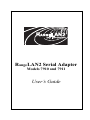
RangeLAN2 Serial Adapter
Models 7910 and 7911
User’s Guide
Copyright
© 1999 Proxim, Inc., Sunnyvale, CA. All rights reserved. This manual and the
software described in it are copyrighted with all rights reserved. No part of this
publication may be reproduced, transmitted, transcribed, stored in a retrieval
system or translated into any language in any form by any means without the
written permission of Proxim, Incorporated.
Trademarks
RangeLAN, the RangeLAN logo, RangeLAN2, and Proxim are trademarks of
Proxim, Inc. All other trademarks are the property of their respective owners.
Limited Warranty, Disclaimer, Limitation Of Liability
For a period of one (1) year from the date of purchase by the retail customer,
Proxim warrants the RangeLAN2 Serial Adapter against defects in materials
and workmanship. Proxim will not honor this warranty if there has been any
attempt to tamper with or remove the Adapter's external foil label.
This warranty does not cover and Proxim will not be liable for any damage or
failure caused by misuse, abuse, acts of God, accidents, or other causes
beyond Proxim’s control, or claim by other than the original purchaser.
If, after inspection, Proxim determines there is a defect, Proxim will repair or
replace the Adapter at no cost to you. To return defective merchandise to
Proxim please call Proxim Technical Support at: (408) 731-2640 to obtain a
Return Merchandise Authorization (RMA) Number.
In no event shall Proxim, Incorporated be responsible or liable for any damages
arising:
❑ From the use of the product;
❑ From the loss of use, revenue or profit of the product; or
❑ As a result of any event, circumstance, action, or abuse beyond the control
of Proxim, Incorporated;
Whether such damages be direct, indirect, consequential, special, or otherwise
and whether such damages are incurred by the person to whom this warranty
extends or a third party.
Part # 7360.0098
Rev. B
i
Warranty Return Policy
If you have a problem with your RangeLAN2 product, please call Proxim
Technical Support at (408) 731-2640. Proxim Technical Support will assist with
resolving any technical difficulties you may have with your Proxim product.
If your product is found to be defective, you may return the product to Proxim
after obtaining an RMA (Return Materials Authorization) number from Proxim
Technical Support. The product must be returned in its original packaging. The
RMA number should be clearly marked on the outside of the box. Proxim cannot
be held responsible for any product returned without an RMA number, and no
product will be accepted without an RMA number.
FCC WARNING
This equipment has been tested and found to comply with the limits for a Class
B digital device, pursuant to Part 15 of the FCC Rules. These limits are designed
to provide reasonable protection against harmful interference in a residential
installation. This equipment generates, uses, and can radiate radio frequency
energy and, if not installed and used in accordance with the instructions, may
cause harmful interference to radio communications. However, there is no
guarantee that interference will not occur in a particular installation. If this
equipment does cause harmful interference to radio or television reception,
which can be determined by turning the equipment off and on, the user is
encouraged to try to correct the interference by one or more of the following
measures:
❑
❑
❑
❑
Reorient or relocate the receiving antenna.
Increase the separation between the equipment and the receiver.
Connect the equipment into an outlet on a circuit different from that
which the receiver is connected.
Consult the dealer or an experienced radio/TV technician for help.
ii
Contents
1. Introduction ................................................................. 1
The RangeLAN2 Family ......................................................................... 2
System Requirements .............................................................................. 3
The Product Package ............................................................................... 3
2. Quick Installation ........................................................ 5
3. Wireless Topologies .................................................. 9
Point-to-Point ........................................................................................... 9
Point-to-Multipoint ................................................................................ 11
Point-to-Point Using RangeLAN2 Infrastructure ................................. 13
Point-to-Multipoint Using a RangeLAN2 Access Point
as a Base Unit ........................................................................................ 15
4. Pass-through and Packetized Modes ..................... 17
5. Understanding the Hardware ................................... 19
Rotary Switches ..................................................................................... 19
The Pairing Domain ............................................................................ 20
LED Indicators ....................................................................................... 22
Serial Port Specification ........................................................................ 26
Antenna Options .................................................................................... 28
Mounting Options .................................................................................. 28
6. Configuration ............................................................ 31
Displaying the Configuration Menu ...................................................... 31
7. Radio Configuration Menu ....................................... 35
Radio Parameters ................................................................................... 36
8. Network Configuration Menu ................................... 45
Network Parameters ............................................................................... 46
9. Serial Configuration Menu ....................................... 49
Serial Parameters ................................................................................... 50
iii
10. Advanced Configuration Menu .............................. 55
Advanced Parameters ............................................................................ 56
11. Display Parameter Values ...................................... 61
12. View Statistics ......................................................... 63
Serial Errors Statistics ........................................................................... 64
Packetized Mode Statistics .................................................................... 64
TCP/IP Statistics .................................................................................... 64
Radio Statistics ...................................................................................... 64
13. Performance Hints .................................................. 65
Microwave Ovens .................................................................................. 65
Range ...................................................................................................... 65
14. Troubleshooting ...................................................... 67
How to Obtain Help with Your Installation .......................................... 67
LED Error Codes ................................................................................... 67
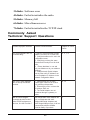
Commonly Asked Technical Support Questions .................................. 68
A. Packetized Mode Specification ............................... 70
Overview ................................................................................................ 70
Pass-through Versus Packetized Mode ............................................... 70
PPX-1 Protocol ...................................................................................... 73
Modem Command Protocol (MCP) ...................................................... 74
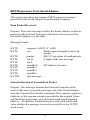
MCP Command Messages to the Serial Adapter ............................... 75
MCP Responses From Serial Adapter ................................................. 81
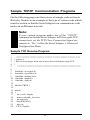
B. Serial Adapter TCP/IP Specification ....................... 87
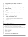
Sample TCP/IP Communication Programs ........................................... 91
Sample TCP Receive Program ............................................................ 91
Sample TCP Send Program ................................................................. 94
Sample UDP Receive Program ........................................................... 96
Sample UDP Send Program ................................................................ 97
C. Menu Structure ....................................................... 100
iv
D. Parameters .............................................................. 107
Radio Parameters .................................................................................
Network Parameters .............................................................................
Serial Parameters .................................................................................
Advanced Configuration Parameters ...................................................
107
108
109
110
E. Procedure for Downloading New Software .......... 111
F. Glossary ................................................................... 113
G. How to Reach Technical Support ......................... 115
H. U.S. Specifications ................................................. 116
Index ............................................................................. 117
v
1. Introduction
Congratulations on your purchase of the RangeLAN2 791x
Serial Adapter, the radio module that replaces RS-232 serial
cables with wireless RF (Radio Frequency) technology. By
attaching a pair of RangeLAN2 Serial Adapters to the serial port
of any two devices, you can transmit and receive data without
the use of wires.
The RangeLAN2 791x can support several data rates and uses
the same patented 2.4 GHz frequency hopping spread spectrum
(FHSS) technology as found within Proxim’s award-winning
RangeLAN2 product line. The Serial Adapter is designed to
work with numerous off-the-shelf applications as well as with
custom programs. The RangeLAN2 791x may leverage off of an
existing RangeLAN2 network, allowing two Serial Adapters to
communicate over greater distances.
The Serial Adapter is designed to be a “plug and play” product.
External rotary switches allow you to configure your Serial
Adapter manually so that in many cases, you will be able to use
a Serial Adapter without running any software to configure it.
However, the Serial Adapter supports a wide variety of configurations that can be easily changed to fit your application requirements. All configuration information is stored in non-volatile
memory called EEPROM (electronically erasable programmable
read-only memory).
Proxim is the leading supplier of spread spectrum radio networking technology for local area environments. Proxim’s unmatched spread spectrum networking expertise, combined with
the company’s extensive experience serving the communication
needs of the mobile computing user, has kept Proxim at the
forefront of the emerging wireless market.
1
The RangeLAN2 Family
RangeLAN2 791x Serial Adapter is part of a family of highperformance products that provides a complete wireless networking solution.
❑ RangeLAN2 7100 is a wireless LAN adapter that fits
into a standard PC/AT ISA bus slot.
❑ RangeLAN2 7400 is a wireless LAN adapter which fits
into a PCMCIA Type II slot on a portable notebook,
laptop, or pen-based computer.
❑ RangeLAN2 7510/752x Access Points allow
RangeLAN2 products to seamlessly connect to a wired
Ethernet network.
❑ RangeLAN2 753x Access Points allow RangeLAN2
products to seamlessly connect to a wired Token Ring
network.
❑ RangeLAN2 754x Extension Point extends the coverage area of an existing RangeLAN2 network.
❑ There are two models of the RangeLAN2 Serial
Adapter, the 7910 and 7911. The 7910 has 100 mW of
output power, while the 7911 has 500 mW of output
power.
❑ RangeLAN2 792x Ethernet Adapter converts any
Ethernet-ready device into a wireless node on an existing RangeLAN2 network.
2
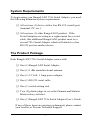
System Requirements
To begin using your RangeLAN2 791x Serial Adapter, you need
the following minimum system requirements:
❑ At least one (1) device with a free RS-232 (serial) port
(terminal, PC, etc.).
❑ At least one (1) other RangeLAN2 product. If the
Serial Adapters are acting as a replacement for a serial
cable, this additional RangeLAN2 product must be a
second 791x Serial Adapter which will attach to a free
RS-232 port on another device.
The Product Package
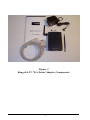
Each RangeLAN2 791x Serial Adapter comes with:
❑ One (1) RangeLAN2 Serial Adapter.
❑ One (1) 1 dBi omnidirectional antenna.
❑ One (1) 12 Volt, 1 Amp power adapter.
❑ One (1) RS-232 serial cable.
❑ One (1) switch setting tool.
❑ Two (2) plastic plugs to cover the Domain and Station/
Master rotary switches.
❑ One (1) RangeLAN2 791x Serial Adapter User’s Guide.
If any of these items are missing or damaged, please contact
your reseller or Proxim Technical Support.
3
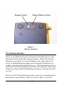
Figure 1
RangeLAN2 791x Serial Adapter Components
4
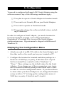
2. Quick Installation
You may follow the quick installation and configuration steps if
all of the following conditions are true:
❑ You will use all of the software default values.
❑ You are using two (2) RangeLAN2 Serial Adapters as a
replacement for an RS-232 cable.
❑ You are using no more than nine (9) pairs of Serial
Adapters in one location.
Follow the steps below to install two RangeLAN2 791x Serial
Adapters:
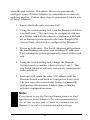
1. Firmly screw the antenna onto its connector in a clockwise rotation. The antenna connector is located on the
side of the unit as shown in Figure 2.
Note:
Government regulatory agencies mandate that the antenna not be alterable. Therefore, the RangeLAN2
Serial Adapter uses a custom antenna connector. Do
not attempt to use a non-certified Proxim antenna or
you may damage the connector and the Serial Adapter.
5
Figure 2
Attachment of the RangeLAN2 Serial Adapter Antenna
2. Attach one end of an RS-232 cable to the RangeLAN2
Serial Adapter and the other end to a free serial port of a
communication device, such as a terminal or a computer. Perform this step with both Serial Adapters.
3. Each RangeLAN2 791x Serial Adapter is preconfigured
to operate as a Station. Therefore, before two Serial
Adapters will communicate, one must be set as a Master. Using the Station/Master rotary switch on the
underside of the RangeLAN2 Serial Adapter, set one
unit of each Serial Adapter pair as a Master and leave
the second unit as a Station.
6
4. Each RangeLAN2 791x Serial Adapter is preconfigured
to use Domain 0. If you have multiple pairs of Serial
Adapters and each pair consists of one Master and one
Station, set each pair to a unique Domain number.
Using the Domain rotary switch on the underside of the
RangeLAN2 Serial Adapter, set each pair to a unique
Domain number from 0-8 to ensure minimal interference. If you decide to use Domain 8, refer to Chapter 5
for information concerning this switch setting’s role in
the Pairing Domain communication feature.
Note:
Do not set the Serial Adapter to use Domain 9 on the
Domain rotary switch. Setting the Domain rotary
switch to 9 will send the Serial Adapter into a configuration mode, and the unit will not be operational.
5. Plug the power supply into the RangeLAN2 Serial
Adapter DC power jack, located on the rear panel, and
plug the power supply into an AC outlet. Upon completing this step, the LED indicator on the top panel of
the unit will glow yellow and then turn green, indicating
that the unit is ready for operation.
6. Your RangeLAN2 Serial Adapters are now ready for
use with your desired application. However, if your
RangeLAN2 Serial Adapters fail to communicate or fail
to exchange information, you may need to compare
your application’s settings with the RangeLAN2 Serial
Adapter’s default values. Please consult Chapter 6 for
information on how to customize your RangeLAN2
Serial Adapter configuration and Chapter 14 for troubleshooting suggestions.
7
8
3. Wireless Topologies
The RangeLAN2 Serial Adapter supports numerous wireless
topologies. The following sections describe four (4) basic
wireless configurations supported by the RangeLAN2 Serial
Adapter: Point-to-Point, Point-to-Multipoint, Point-to-Point
using RangeLAN2 Infrastructure, and Point-to-Multipoint using
a RangeLAN2 Access Point as a Base Unit.
Point-to-Point
In this topology, a pair of RangeLAN2 Serial Adapters are
configured to exclusively communicate with each other.
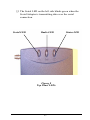
Figure 3
Point-to-Point Topology
9
In Figure 3 above, Serial Adapters 1 and 2 can communicate
with each other, as can Serial Adapters 3 and 4. Even though all
four units may be in range of one another and may “hear” the
others’ messages, each unit will filter out messages not intended
for it. Since this topology establishes a one-to-one, MasterStation relationship between two Serial Adapters, it acts as a
wireless substitute for an RS-232 cable in a wide variety of
applications.
Using the TCP/IP protocol as the transport mechanism for
information, a Serial Adapter that receives a message from its
serial port will turn the message into a data packet that includes
the transmitting unit’s IP address and the destination unit’s IP
address.
The transmitting Serial Adapter will then “listen” on the radio
frequency to ensure that the other Serial Adapter is not transmitting a packet. If free, the unit will transmit the packet. It will
wait for an acknowledgment from the receiving Serial Adapter
that the packet was received without error. If it does not receive
such an acknowledgment and it has not exceeded its maximum
retry count, the unit will retransmit the packet.
A receiving Serial Adapter will filter packets based on the
packet’s destination IP address. Only the unit with the correct IP
address will save the packet and send an acknowledgment back
to the source unit. Upon receiving a packet, the unit will also
extract the original message out of the packet and send it out
over the serial port. If there is an error in the packet, the unit
will ignore it. This guarantees the delivery of only error-free
transmissions.
10
Point-to-Multipoint
The RangeLAN2 Serial Adapter may also operate in a Point-toMultipoint topology. This configuration provides added flexibility, allowing one centralized unit, operating in Packetized mode,
to communicate with multiple units placed in remote locations.
When operating in Packetized mode, a central Serial Adapter
may be programmed to send either directed messages or broadcasts to other Serial Adapters, by specifying the appropriate IP
address and send mode. The Packetized Mode Command Set
allows users to customize Serial Adapter communications to
meet their application needs. For more information on
Packetized mode, please see Ch. 4 and Appendix A, the
Packetized Mode Specification.
A Point-to-Multipoint topology may utilize the Broadcast mode,
so that multiple Serial Adapters can receive the same information simultaneously. Note that a broadcasting Serial Adapter
does not wait for an acknowledgment of the packet’s receipt
from any receiving unit. Broadcast mode is an unacknowledged
service because it can be extremely inefficient to have every unit
acknowledge a message once a packet is received. Since these
broadcast packets are unacknowledged, a unit cannot retry
transmissions when in this sending mode. You may use the
Packetized Mode Command Set or another high-level application in conjunction with the Broadcast mode to guarantee the
delivery of error-free transmissions to multiple units.
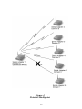
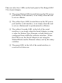
In Figure 4 below, Serial Adapters 1 through 5 are on Domain
0. Serial Adapter 1 is set to Broadcast mode. Serial Adapter 6 is
on Domain 1. Whenever a message is sent from unit 1, it is
received by units 2 through 5 and is processed by those units
which receive the transmission error-free. Since unit 6 is on a
different Domain, it will not process unit 1’s broadcast message.
11
Figure 4
Point-to-Multipoint
12
Point-to-Point Using RangeLAN2 Infrastructure
You may also use your existing RangeLAN2 infrastructure and
network to increase the range and flexibility of communications
between Serial Adapters. A Serial Adapter configured as a
Station may synchronize to a RangeLAN2 Access Point which
has the same Domain and Security ID.
Two Serial Adapters which are positioned out of range of one
another, can be set as Stations so that each will synchronize to a
RangeLAN2 Access Point. Then, the Access Point(s) will
forward the radio signals sent between the units. This allows the
units to communicate as if they were actually in range of one
another.
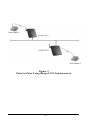
For example, in Figure 5 below, Serial Adapter 1 is synchronized to Access Point 1, and Serial Adapter 2 is synchronized to
Access Point 2. Access Points 1 and 2 are on the same Ethernet
network. Serial Adapters 1 and 2 can engage in Point-to-Point
communications, even though they are not in range of one
another. Access Point 1 forwards packets from Serial Adapter 1
to Access Point 2, which then transmits the packets to Serial
Adapter 2.
13
Figure 5
Point-to-Point Using RangeLAN2 Infrastructure
14
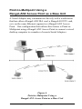
Point-to-Multipoint Using a
RangeLAN2 Access Point as a Base Unit
A Serial Adapter may communicate directly with a workstation
that has either a RangeLAN2 ISA card, a RangeLAN2 PC card,
or is on the same Ethernet segment as a RangeLAN2 Access
Point. One configuration that utilizes this feature is Point-toMultipoint using a RangeLAN2 Access Point to connect a wired
desktop computer to a number of remote Serial Adapters.
Figure 6
Point-to-Multipoint Using a
RangeLAN2 Access Point as a Base Unit
15
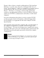
Figure 6 above shows a simple configuration of this topology.
Desktop 1 is on the same network as a RangeLAN2 Access
Point. Serial Adapters 1 and 2 are configured as Stations and are
synchronized to the Access Point, which is configured as a
Master. Desktop 1 is running a custom-made application
written in a programming interface, such as Windows Sockets,
which uses TCP/IP to communicate with either or both Serial
Adapters.
For more information about how to write a custom TCP/IP
sockets program which will interface with the RangeLAN2
Serial Adapter, see Appendix B, the Serial Adapter TCP/IP
Specification.
The topologies discussed above display only a small number of
the simplest configurations available with the RangeLAN2
Serial Adapter. You may also design more complicated custom
topologies that meet your own communication requirements and
that build upon the principles presented within these simpler
configuations.
Note:
When using the Serial Adapters in conjunction with an
Ethernet backbone, note that you can not send a broadcast message through a router.
16
4. Pass-through and Packetized Modes
The Serial Adapter’s serial interface can be set for two kinds of
operating modes: Pass-through mode and Packetized mode. The
format of the information presented to the unit’s serial port is
dramatically different depending on which of these modes is
selected.
You should use the Pass-through mode for applications where a
pair of RangeLAN2 Serial Adapters replace an RS-232 cable
without changing the existing serial application. In Pass-through
mode, the unit accepts a stream of serial data at its RS-232 port
and passes it over the radio network to a receiving unit or units.
The data arrives at the receiving unit that then sends this information to its attached computer or terminal over the serial port.
Pass-through mode is the default setting for the Serial Adapter.
In Packetized mode, the Serial Adapter accepts a set of commands from an external computer. This allows the external
computer to control the unit. In addition to commands that cause
the unit to transmit messages over the radio, the unit also accepts
configuration commands such as “switch radio to Channel 2” or
“switch baud rate to 9600 baud.” Packetized mode has the
advantage that it permits an external computer to control the
more advanced features of the unit “on the fly.”
A unit operating in Packetized mode can communicate with
another unit operating in either Pass-through or Packetized
mode.
Note:
Please review Appendix A, the Packetized Mode Specification, before attempting to operate the Serial Adapter
in Packetized mode.
17
18
5. Understanding the Hardware
Rotary Switches
The RangeLAN2 Serial Adapter is designed for easy configuration by setting two rotary switches located on the bottom of
the unit. The rotary switches are shown in Figure 7 below. Use
the switch setting tool, enclosed in the product package, to
change the position of the rotary switches.
❑ The Station/Master Switch allows the user to externally
set the unit as either a Master or a Station within a
wireless network. The Serial Adapter is pre-configured
so that the switch is set as a Station.
❑ The Domain Switch allows the user to set the Domain
number to a value between 0 and 8. The Serial Adapter
is pre-configured to operate using Domain 0. If you
want to set the Domain to a number between 9 and 15,
you must use the software configuration menu. See
Chapter 6 for information on how to access the Serial
Adapter’s software configuration menu.
Note:
Setting the RangeLAN2 Serial Adapter to Domain 9 will
cause the unit to exit from operating mode and enter the
configuration menu at 9600 bps, 8N1. Also, when the
Domain Switch is set to 9, each time the RangeLAN2
Serial Adapter is turned on, it will boot up into the
configuration menu.
19
Domain Switch
Station/Master Switch
Figure 7
Rotary Switches
The Pairing Domain
There is an additional feature associated with Domain 8 on the
Domain Switch called the Pairing Domain. When the Pairing
Domain is not used, two Serial Adapters will each send out a
series of handshaking messages and exchange IP addresses to
enable communication during boot-up. This information is lost
each time the Serial Adapter is powered off; therefore, the Serial
Adapter performs this handshaking procedure each time the unit
is reset.
However, the Pairing Domain feature stores the communication
information permanently within the unit so that it is not lost
20
when the unit is reset. This allows the user to permanently
configure a pair of Serial Adapters to communicate exclusively
with one another. Follow these steps to permanently bind a pair
of Serial Adapters:
1. Ensure that both units are turned off.
2. Using the switch setting tool, turn the Domain Switch to
8 on both units. The units may be configured with one
as a Master and with the other as a Station or with both
set as Stations synchronized to the same RangeLAN2
Access Point, which is also configured for Domain 8.
3. Power up both units. The Serial Adapters will perform
the handshaking procedure and exchange IP addresses.
This information is then permanently stored within each
unit.
4. Using the switch setting tool, change the Domain
Switch from 8 to another value between 0 and 7. The
two Serial Adapters will now exclusively communicate
with each other.
5. Each unit will retain the other’s IP address until the
Domain Switch is set back to 8 and power is recycled.
The user may also override this feature by manually
configuring a Destination Address from within the
software configuration menu.
Note:
If you intend to use the Pairing Domain feature to bind
together two Serial Adapters, Proxim recommends that
you do not set any pair of units to communicate on
Domain 8, in order to avoid unintended pairings.
21
To reset the unit back to the default setting, manually set the
Destination Address to 0.0.0.0 or reset the unit to factory defaults from within the software configuration menu.
When using this feature, have only two Serial Adapters configured to Domain 8 on the rotary switch at any point in time. If
only one unit is configured for Domain 8, the Pairing Domain
will not change the unit’s configuration. If three Serial Adapters
are set to Domain 8 and then powered on, the outcome will be
unpredictable and may not result in a successful pairing of two
of the units.
The Pairing Domain feature is only available when the Domain
Switch is in use. This feature is not operational when a Serial
Adapter has been configured to Domain 8 from within the
software configuration menu or when the Domain Switch setting
has been overridden by the software configuration menu.
LED Indicators
There are three LEDs on the top panel of the RangeLAN2 791x
Serial Adapter:
❑ The Status LED on the right side (with the unit orientated so that you can read the Proxim logo), changes
colors from yellow (initializing) to green (operational).
This LED blinks red in a repeating pattern when a
problem occurs with the unit. See Chapter 14 for a
further discussion of these patterns.
❑ The Radio LED in the center blinks yellow when the
Serial Adapter is transmitting data packets over its
radio.
22
❑ The Serial LED on the left side blinks green when the
Serial Adapter is transmitting data over the serial
connection.
Serial LED
Radio LED
Figure 8
Top Panel LEDs
23
Status LED
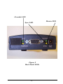
There are also four LEDs on the back panel of the RangeLAN2
791x Serial Adapter:
❑ The green Master LED, located between the DC power
jack and the serial interface, is on steady when the unit
is set as a Master.
❑ The yellow Sync LED, located between the DC power
jack and the serial interface, is on steady when the unit
is set as a Station and is synchronized to a Master.
❑ The yellow Override LED, to the left of the serial
interface, is on steady when the Serial Adapter is using
a value for Station Type, Domain, or both which was
configured from within the software interface. When
this LED is on, the Serial Adapter is not using the
Station/Master and/or Domain value(s) set by the rotary
switches.
❑ The green LED, to the left of the serial interface, is
reserved for future use.
24
Override LED
Sync LED
Figure 9
Back Panel LEDs
25
Master LED
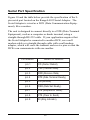
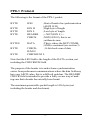
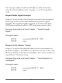
Serial Port Specification
Figure 10 and the table below provide the specification of the 9pin serial port located on the RangeLAN2 Serial Adapter. The
Serial Adapter is wired as a DCE (Data Communication Equipment), like a modem.
The unit is designed to connect directly to a DTE (Data Terminal
Equipment), such as a computer or dumb terminal, using a
straight-through RS-232 cable. If your application requires that
the Serial Adapter be connected to another DCE, use a null
modem cable or a straight-through cable with a null modem
adapter, which will cross the transmit and receive pins so that the
DCEs can communicate with one another.
Pin Numb e r
Se rial Pin Functio n
p in 1
CD (Carrie r De te ct)
p in 2
TXD (Transmit Data)
p in 3
RXD (Re ce ive Data)
p in 4
DTR (Data Te rminal Re ad y)
p in 5
SG (Gro und )
p in 6
DSR (Data Se t Re ad y)
p in 7
RTS (Re q ue st to Se nd )
p in 8
CTS (Cle ar to Se nd )
p in 9
RI (Ring Ind icato r)
26
Figure 10
Serial Port Specification
27
Antenna Options
The Serial Adapter is shipped with a standard directly-connected
antenna. To install the antenna, screw it clockwise onto the
antenna connector. Proxim sells several antenna alternatives,
including higher gain omnidirectional and directional antennas.
Each of these antennas ship with installation and mounting
instructions. For information on additional antenna options,
please contact your Proxim Sales Representative.
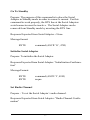
Mounting Options
The Serial Adapter was designed to sit on a flat surface. However, there are four pre-threaded holes on the underside of the
unit so that it may be mounted on any surface. The mounting
holes are shown in Figure 11. These holes are a #6-32 tap and
0.175" deep. Screws and mounting tools are not provided by
Proxim.
Note:
When mounting the Serial Adapter onto a flat surface,
you may need to remove the plastic feet from the
underside of the unit so that the mounting holes are flush
against the mounting surface. The plastic feet are glued
onto the underside of the unit and can be removed with
a small flat-head screwdriver.
28
2.75”
2.10”
Figure 11
Mounting Holes
29
30
6. Configuration
You need to configure the RangeLAN2 Serial Adapter using the
software menus if any of the following conditions apply:
❑ You plan to operate a Serial Adapter in broadcast mode.
❑ You want to set Security IDs on your Serial Adapters.
❑ You want to operate in Packetized mode.
❑ You need to change the software default values, including IP addresses.
In order to configure a Serial Adapter, you need a terminal or
terminal emulation program, such as Hyperterminal or
Quarterdeck’s Procomm Plus, to access the Serial Adapter
configuration menu. Hyperterminal is shipped with Microsoft
Windows 95.
Displaying the Configuration Menu
1.
Attach one end of an RS-232 cable to the Serial Adapter and
the other end to a free serial port on your terminal or PC.
2.
Configure the terminal or terminal emulation package to a
baud rate of 9600 bps, no parity, 8 data bits and 1 stop bit.
Set the terminal flow control to either “Hardware” or
“None.” These settings are the default values for the Serial
Adapter; if you change any of these parameters, your terminal or terminal emulation package must match those values
in order to view the configuration menu. If you do not know
to what values your Serial Adapter is set, change the Domain
rotary switch to “9” to bring up the configuration menu at
9600 bps, no parity, 8 data bits and 1 stop bit.
31
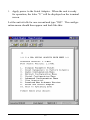
3.
Apply power to the Serial Adapter. When the unit is ready
for operation, the letter “U” will be displayed on the terminal
screen.
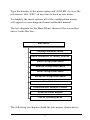
Let the unit sit idle for one second and type “$$$”. The configuration menu should then appear and look like this:
32
Type the number of the menu option and <ENTER> to view the
sub-menus. Hit <ESC> at any time to back up one menu.
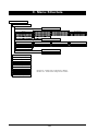
To simplify the menu options, all of the configuration menus
will appear in a tree diagram format within this manual.
The tree diagram for the Main Menu, shown in the screen shot
above, looks like this:
M ain M enu
D isplay Param eter Valu es
R eset Param eters to F acto ry D efau lts
R adio C on figu ration M enu
N etw o rk C o n fig uratio n M en u
Serial C o nfig uratio n M enu
Ad van ced C o n fig uratio n M en u
View Statistics
D ow n load N ew So ftw are Version
R eset the Serial Adap ter
Exit to Operatin g M o de
The following six chapters detail the sub-menus, shown above.
33
34
7. Radio Configuration Menu
This section discusses the Radio Configuration values that can
be manually configured by the user.
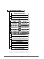
The software tree below shows the options available in the Radio
Configuration Menu:
S e ria l Ad a pter M a in M e nu
D ispla y Pa ra m eter V a lu e s
R ese t Pa ra m eters to F ac to ry D efau lts
R ad io C on figu ra tion M e n u
D o m ain
C ha n ne l
S u bc h an n el
S ta tio n T yp e
M aste r N a m e
S ec u rity ID
E n ab le R e pe a tin g
M AC Optim ize
In ac tivity T im e ou t
R oa m C on fig
R o am ing E na b le d
R ese t R a dio
N etw o rk C o nfig ura tion M e n u
S eria l C on figu ra tion M e n u
Adva n ce d C o n fig u ratio n M en u
V ie w S ta tistic s
D ow n loa d N e w S o ftw a re V ersion
R ese t th e S e ria l Ad a pte r
E xit to Op eratin g M od e
D otted L in e - V is ib le w h en c on fig u red as a M as ter
D as h ed L in e - V is ib le w h en c on fig u red as a S tation
35
Radio Parameters
The table below shows the range and default values for each of
the Radio parameters:
Parame te r Name
Rang e
De fault
Do main
0-15, and "U" fo r Use
Switch
Use Switch
Channe l *
1-15, and 0 fo r
auto matic se le ctio n
0
Sub channe l *
1-15
1
Statio n Typ e
Maste r, Statio n,
and "U" fo r Use Switch
Use Switch
Maste r Name *
11 characte rs
MASTER
Se curity ID
20 characte rs
b lank
Enab le Re p e ating *
Y/ N
N
MAC Op timize *
No rmal, Lig ht, Ve ry
Lig ht, and Auto
Auto
Inactivity Time o ut t
0 fo r no time o ut and 1,
2, 3, ... to d e sig nate
inte rvals o f 10 se co nd s
0
Ro am Co nfig
Slo w, No rmal, and Fast
No rmal
Ye s/No
Ye s
-
-
t
Ro aming Enab le d
t
Re se t Rad io
* Only visib le whe n
co nfig ure d as a Maste r
t
Only visib le whe n
co nfig ure d as a Statio n
36
Note that changes to these parameters will not take effect until
either the radio or the Serial Adapter is reset.
A RangeLAN2 Serial Adapter may be set as either a Master or a
Station using the Station Type parameter within the configuration menu. You may also choose “U” for Use Switch to use the
value specified by the Station/Master Switch. The rotary switch
is set to Station by default.
Proxim’s RangeLAN2 products are frequency hopping spread
spectrum radios which communicate in the 2.4 GHz frequency
band. This means that several times every second, the frequency
at which the units are communicating changes.
In order for the units to communicate, in each subnetwork there
must be one unit that coordinates the frequency hops. This unit
is called the Master. It might help you to think of the Master as
the conductor of a frequency hopping orchestra. The Master
keeps time so all units know when to hop and to what frequency.
Units classified as Stations synchronize to the Master and follow
its signal to learn what frequency in the pattern the Master is
currently using.
There must be at least one unit in a given topology designated
the Master. When using two units in a Point-to-Point topology,
one RangeLAN2 Serial Adapter will be the Master and the other
will be set as a Station. In a Point-to-Multipoint topology, there
will be one Master and all other units are configured as Stations.
However, if you are using a topology that connects a
RangeLAN2 Serial Adapter to a RangeLAN2 Access Point, the
RangeLAN2 Access Point will be the Master and each Serial
Adapter should be set as a Station.
37
In order to establish communications, all Stations and the Master
must be configured with the same Domain number. Radios on
different Domains cannot communicate with each other. The
Domain is a software filter which does not affect the actual radio
frequency or the frequency hopping sequence.
You typically want to set each Serial Adapter in a given network
to the same Domain. However, if you have two sets of Serial
Adapters in two distinct pairs which you do not want to communicate with one another, you should set each pair to a different
Domain to avoid confusion.
The Domain is a number between 0 and 15. Choose “U” for Use
Switch in order to use the number specified by the Domain
Switch. The default setting is the Domain Switch value, which
is pre-configured to Domain 0 at the factory.
Note that while the Domain Switch allows the user to set the
Serial Adapter to operate on any Domain value between 0 and 8,
the software configuration menu allows the user to set the
Domain to a value between 0 and 15. Also, if you choose to
override the Domain Switch, the Pairing Domain feature, described in Chapter 5, will not be operational.
While you may set the Domain number to 9 in the configuration
menu, choosing Domain 9 on the external rotary switch will
cause the Serial Adapter to enter the configuration menu at the
default parameters of 9600 bps and 8N1.
Note:
If the Serial Adapter is reset at any time while the
external rotary Domain Switch is set to 9, it will immediately enter the configuration menu and will not be
ready for operation.
38
Each Master can select one of 15 Channels to establish communication with its Stations. Each Channel number sets a unique
frequency hopping sequence allowing for multiple subnetworks
with higher data rate transmission capability in the same air
space.
You may think of the Channel as a pipe. In order to communicate, radios must be on the same Channel and there must be one
(and only one) Master that provides the timing for that Channel.
There are 15 independent Channels available for use with
RangeLAN2 products. This means that there are 15 different
sequences of frequency hops. Each Channel is at a different
frequency at a different time. To minimize interference, set each
Serial Adapter acting as a Master within the same vicinity to a
different Domain and Channel.
The Serial Adapter’s Channel may be set to a value between 0
and 15, and 0 is the default setting. When set to Channel 0, a
Serial Adapter automatically selects a Channel upon boot-up
based on the configured Domain number. The Channel selected
is the Domain number plus 1. Therefore, if the Domain is set to
0, the Channel is 1. Note that the automatic selection procedure
will choose Channel 15 when set to either Domain 14 or 15.
This parameter is visible only when the Serial Adapter is set as a
Master. All Stations will determine their Channel by the Master
to which they are synchronized.
The Subchannel is a software code that is appended to each
radio packet. It does not affect the frequency hopping sequence
like a Channel does. Use a Subchannel if you need more than 15
Masters in the same area and, therefore, all of the Channels are
in use.
39
For example, you can use Channel 1, Subchannel 1 for Adapter
Pair A and Channel 1, Subchannel 2 for Adapter Pair B. The
two pairs will not communicate with one another. However,
they are still sharing the 1.6 Mbps pipe since they are both using
Channel 1.
The Subchannels are designated 1 through 15, and 1 is the
default setting. This parameter is visible only when the Serial
Adapter is set as a Master.
The optional Master Name parameter of up to 11 characters
specifies an alphanumeric name to simplify the identification of
each Master in your wireless topology. This parameter is visible
only when the Serial Adapter is set as a Master.
To further improve the security of a wireless topology, each unit
requires the same Security ID to establish communication. The
Security ID may be set on both Masters and Stations. This ID is
encrypted and stored within the RangeLAN2 Serial Adapter
itself, not in software. It cannot be accessed, but you may
change it. However, if you do change it, then you will need to
change the Security ID on all of the other radios to the same new
value to reestablish communication.
The Security ID parameter can be up to 20 characters and is an
empty string by default. There are 1,048,576 unique choices for
the Security ID.
Note:
The Security ID value is not a software parameter but is
stored within the Serial Adapter’s radio. Therefore, if
you choose the Reset Parameters to Factory Defaults
option from within the Serial Adapter Main Menu, the
Security ID will not be reset to its default value.
40
The Repeating Enabled parameter gives the ability to enable or
disable the RangeLAN2 repeating feature. When enabled, a
Serial Adapter, acting as a Master, may repeat signals coming
from one Station and destined for another Station. These two
Stations must be out of range of one another, but both in range of
the Master Serial Adapter for repeating to occur. However, be
aware that by enabling the repeating feature, the network
throughput will drop by as much as one-half when repeating
occurs.
This parameter is only visible when the Serial Adapter is configured as a Master. By default, Repeating is disabled.
The MAC Optimize parameter can help improve throughput for
small networks. The default setting of Auto causes the
RangeLAN2 Serial Adapter to determine the number of units
synchronized to it and adjust this parameter accordingly.
Alternatively, you may set this parameter to one of the other
settings. If you have 0 or 1 wireless nodes communicating with
a RangeLAN2 Serial Adapter, set this parameter to Very Light.
If you have between 2 and 7 wireless nodes communicating with
a RangeLAN2 Serial Adapter at the same time, set this parameter to Light. In networks with more than 7 concurrent wireless
users, set the parameter to Normal.
This parameter is visible only when the Serial Adapter is set as a
Master.
To conserve battery life, the RangeLAN2 Serial Adapter has an
Inactivity Timeout sleep mode. The sleep mode is automatically engaged when a certain period of time has elapsed since the
computer has sent or received data over the network. Once the
adapter is asleep, it can be awakened by a Master attempting to
send data to it.
41
There is no inactivity timeout set by default, but you may
change this to any interval of 10 seconds. This parameter is
visible only when the Serial Adapter is set as a Station. A
Master unit does not have a sleep mode.
Note:
Configuring a Serial Adapter with an Inactivity Timeout
may cause data loss if any of your units are operating in
UDP or UDP Broadcast mode.
The Roam Config parameter allows you to determine how
quickly a Serial Adapter set as a Station will roam from one
RangeLAN2 Access Point to another. Ignore this parameter if
you have any Serial Adapter set as a Master within your wireless
network. This parameter is only of use in topologies where the
Serial Adapter repeats a signal through an existing RangeLAN2
network with multiple Access Points that provide overlapping
coverage.
In a topology with many RangeLAN2 Access Points that provide
heavy overlapping coverage, set this parameter to Fast to maintain high throughput for each of the wireless radios.
In most wireless networks, set the Roam Config parameter to
Normal. Wireless node throughput will not change noticeably,
and an overabundance of RangeLAN2 Access Points is not
required.
If the wireless coverage area provided by RangeLAN2 Access
Points is sparse, set the Roam Config parameter to Slow. Wireless nodes will not roam until they are nearly out of range of a
RangeLAN2 product. This parameter is visible only when the
Serial Adapter is set as a Station.
42
You may choose to disable a Serial Adapter’s ability to roam
with the Roaming Enabled parameter. This feature is enabled
by default; however, if you want a RangeLAN2 Serial Adapter
to communicate with one and only one other RangeLAN2
product, you may disable this feature.
This parameter is visible only when the Serial Adapter is set as a
Station.
Note:
A Station Serial Adapter can roam only between Proxim
RangeLAN2 Access Points or RangeLAN2 Extension
Points connected to the same Ethernet or wireless
backbone.
43
44
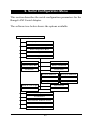
8. Network Configuration Menu
This section describes the network configuration parameters for
the RangeLAN2 Serial Adapter.
The software tree below shows the options available:
M ain M enu
D isplay Param eter Values
R eset Param eters to Factory D efau lts
R adio C o nfiguratio n M en u
N etw ork C on fig uration M en u
Sen d M o de
D estination Add ress
IP Ad dress
Sub net M ask
Lo cal Po rt N u m ber
R em o te Po rt N u m b er
D efault Gatew ay Ad dress
Serial C o nfig uratio n M en u
Advanced C on figu ration M enu
View Statistics
D o w nload N ew So ftw are Version
R eset the Serial Ad apter
Exit to O peratin g M o de
45
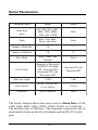
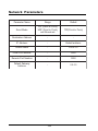
Network Parameters
Parame te r Name
Rang e
De fault
Se nd Mo d e
TCP (Po int to Po int),
UDP (Po int to Po int),
and Bro ad cast
TCP(Po int to Po int)
De stinatio n Ad d re ss
-
-
IP Ad d re ss
-
De fault ad d re ss
Sub ne t Mask
-
255.0.0.0
Lo cal Po rt Numb e r
-
5000
Re mo te Po rt Numb e r
-
5000
De fault Gate way
Ad d re ss
-
0.0.0.0
Send Mode indicates the method which a RangeLAN2 Serial
Adapter will use to communicate with other RangeLAN2 units.
Point-to-Point mode allows a Serial Adapter to transmit packets
to only one other unit whose IP address is configured as the
transmitting unit’s Destination Address.
There are two transport layer protocols supported in Point-toPoint mode: TCP and UDP. TCP offers reliable message delivery but may slow down performance. UDP offers less reliable
message delivery than TCP and may be selected to improve
speed at the cost of reliability.
When a RangeLAN2 Serial Adapter is set to Broadcast mode,
every Serial Adapter which receives the signal error-free and
which is set to the same Domain and Security ID will process the
46
broadcast message. Broadcast mode uses the UDP transport
layer protocol to send data. As stated above, UDP is faster than
TCP but does not ensure reliable message delivery. However, if
your application ensures the reliability of data transmission,
there should be no negative side effects to using the UDP protocol in either Point-to-Point or Broadcast mode. See Chapter 3
for a detailed discussion of the suggested Wireless Topologies.
The Destination Address identifies the IP address to which the
Serial Adapter will send packets. Typically, the Destination
Address will be the IP address of a second Serial Adapter. If
two Serial Adapters are configured as a Master/Station pair, then
each unit will automatically configure its Destination Address
with the other’s IP address, each time the units are powered on.
Two Serial Adapters, both set as Stations and synchronized to
the same RangeLAN2 Access Point or Extension Point, will also
obtain the IP address of the other unit automatically.
As described above, the Destination Address is typically configured automatically by the RangeLAN2 Serial Adapter during
each boot-up. However, the Destination Address may be set
permanently using the Pairing Domain feature, as described in
Chapter 5, or from within the Network Configuration Menu.
Both methods will override the automatic configuration process.
If you have written a custom program to allow a wired workstation to communicate directly with a Serial Adapter, as described
in Appendix B, then you must manually configure the Destination Address with the IP address of the wired workstation. The
IP address of a wired workstation will not be obtained automatically and can not be set using the Pairing Domain feature.
By default, a RangeLAN2 Serial Adapter assigns itself an
unassigned Class A IP Address based upon its unique MAC
address. In cases where the Serial Adapter is used to communi-
47
cate with the wired infrastructure, it will be necessary to change
the default address to one which is on the same subnet as the
wired stations so that IP packets are routed correctly. You can
override the default address using the IP Address option in the
configuration menu. This parameter will not change unit the
Serial Adapter is reset.
Subnet Mask indicates the mask that will be used to determine
on which network the RangeLAN2 Serial Adapter is located.
Local Port Number signifies the port number on which the unit
will receive packets from another Serial Adapter. The default
port number is 5000. Do not change this parameter unless you
experience a port number conflict in your application.
Remote Port Number signifies the port number on which the
unit will send packets to another Serial Adapter. The default
port number is 5000. Do not change this parameter unless you
experience a port number conflict in your application.
If a packet is destined for an IP host or node that belongs to a
different IP subnet, the RangeLAN2 Serial Adapter will send IP
packets to the Default Gateway Address (usually a router) for
the packets to be routed to the proper destination. This parameter will not change until the Serial Adapter is reset.
Note:
If a pair of Serial Adapters are communicating with one
another across a router, you must manually assign each
unit a valid IP address within its subnet and set the
Default Gateway Address and appropriate Destination
Address. You may not use the Pairing Domain feature
to assign Destination Addresses in this scenario.
48
9. Serial Configuration Menu
This section describes the serial configuration parameters for the
RangeLAN2 Serial Adapter.
The software tree below shows the options available:
S e ria l Ad a p te r M a in M e n u
D isp la y Pa ra m e te r V a lu e s
R e se t Pa ra m e te rs to F a c to ry D e fa u lts
R a d io C o n fig u ra tio n M e n u
N e tw o rk C o n fig u ra tio n M e n u
S e ria l C o n fig u ra tio n M e n u
Ba u d R a te
Pa rity
N u m b e r o f S to p Bits
N u m b e r o f D a ta Bits
Echo M ode
F lo w C o n tro l
G e n e ra te X O N /X O F F
R e c o g n iz e X O N /X O F F
G e n e ra te C T S
G e n e ra te D S R
R e c o g n ize D T R
R e c o g n iz e R T S
M a x im u m L in e L e n g th
In p u t T im e o u t
Ad d a D e lim ite r
R e m o ve a D e lim ite r
Ad va n c e d C o n fig u ra tio n M e n u
V ie w S ta tistic s
D o w n lo a d N e w S o ftw a re V e rsio n
R e se t th e S e ria l Ad a p te r
E x it to O p e ra tin g M o d e
49
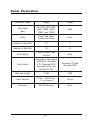
Serial Parameters
Parame te r Name
Rang e
De fault
Baud Rate
(b p s)
300,1200, 2400, 4800,
9600, 19200, 38400,
57600, and 115200
9600
Parity
Eve n, Od d , Mark,
Sp ace , and No ne
No ne
Numb e r o f Sto p Bits
1-2
1
Numb e r o f Data Bits
7-8
8
Echo Mo d e
No ne , Simp le , and
Te rminal
No ne
Flo w Co ntro l
Ge ne rate o r Re co g nize
XON/XOFF, Ge ne rate
CTS, Ge ne rate DSR,
Re co g nize DTR, and
Re co g nize RTS
Ge ne rate CTS and
Ge ne rate DSR
Max Line Le ng th
1-1456
1456
Inp ut Time o ut
50 ms - 300,000 ms,
0 = no time o ut
100 ms
De limite rs
ASCII Characte rs
No ne
The Serial Adapter allows the user to select a Baud Rate of 300,
1200, 2400, 4800, 9600, 19200, 38400, 57600, or 115200 bps.
The default value is 9600 bps. The baud rate controls the rate of
data transfer between the Serial Adapter and an RS-232 serial
port.
50
You may also change the default settings for Parity, Number of
Stop Bits, and Number of Data Bits to match the settings of
your RS-232 application. The Serial Adapter will support any
combination of 7 or 8 data bits, 1 or 2 stop bits, and one of the
following parity settings: even, odd, mark, space, and none.
The Serial Adapter supports three Echo Modes: None, Simple,
and Terminal. When no Echo is selected, the unit will not Echo
the characters typed to the terminal screen. In the Simple Mode,
all characters typed are echoed to the screen, including carriage
returns. The Terminal Echo Mode specifies that the unit should
behave like a terminal by removing the most recent character
from the input stream upon encountering a backspace character
or beeping if backspace is pressed at the beginning of a line.
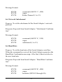
The Serial Adapter supports several Flow Control options:
Generate XON/XOFF, Recognize XON/XOFF, Generate CTS,
Generate DSR, Recognize DTR, and Recognize RTS.
A Serial Adapter will pass flow control pin values over the radio
to a remote Serial Adapter in order to simulate the activity of the
control pins of a null modem cable.
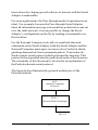
The Serial Adapters will pass control pin values as follows:
Local Serial Adapter
(initiated by host) RTS
(initiated by host) DTR
CTS
←
←
DSR
Remote Serial Adapter
→
→
CTS
DSR
RTS (initiated by host)
DTR (initiated by host)
For example, when the attached RS-232 host asserts the RTS
pin, the Serial Adapter will send this information to the remote
Serial Adapter. In turn, the remote Serial Adapter will assert the
51
CTS pin, notifying the remote RS-232 host that data may be sent
over the connection. This function regulates the data exchange
between two RS-232 hosts.
In addition to this basic function, the Serial Adapter’s flow
control options regulate the data exchange between the Serial
Adapter and its attached RS-232 host. Below is a short description of how each flow control option operates when enabled:
Generate XON/XOFF: When its buffers are full, the Serial
Adapter will send an XOFF character to the attached host as a
signal for the host to stop transmitting data to the unit. Once
space becomes available within its buffers, the Serial Adapter
will send an XON character to the host as a signal to begin
transmission.
Recognize XON/XOFF: If the Serial Adapter receives an XOFF
character from the host, it will stop sending data to the host.
When it receives an XON from the host, the Serial Adapter will
resume transmission.
Generate CTS: The Serial Adapter will inhibit the CTS pin if
its buffers become full, and assert CTS if there is room in its
buffers.
Generate DSR: The Serial Adapter will inhibit the DSR pin if
its buffers become full, and assert DSR if there is room in its
buffers.
Recognize DTR: The Serial Adapter will not send data to the
host unless the DTR pin is asserted.
Recognize RTS: The Serial Adapter will not send data to the
host unless the RTS pin is asserted.
52
The Maximum Line Length refers to the maximum number of
characters the Serial Adapter must receive before transmitting
the message. The maximum value for this parameter is 1456,
which corresponds to the maximum size of an Ethernet packet
minus the space required for the transport layer and other headers.
Setting this parameter to 1 will cause the unit to transmit each
character as a separate packet as soon as the unit receives it.
Since there is time and memory overhead associated with sending each packet, it is best to keep this number as high as is
reasonable for the application. However, in an environment
where many packets are damaged due to some form of interference, it may be more prudent to keep this value from being set
too large.
The Input Timeout specifies the length of time the Serial
Adapter will wait after it has received a character before sending
the accumulated characters as a packet. This value may be set to
between 50 and 300,000 milliseconds. A value of 0 indicates
that no input timeout is set.
The Serial Adapter allows a user to select up to four different
Delimiter characters. The unit looks for the delimiters in the
input stream and sends out a packet upon receipt of one of these
characters. The Serial Adapter will accept any printing ASCII
character (letters, numbers, or punctuation) as a delimiter, along
with blank space and carriage return. Delimiter characters are
transmitted with the data.
A Serial Adapter will accumulate characters until it receives a
Delimiter, reaches the specified Maximum Line Length, or the
length of time specified by the Input Timeout has elapsed.
When one of the these three conditions is met, the Serial Adapter
will transmit the accumulated characters as a packet.
53
54
10. Advanced Configuration Menu
S e ria l Ad ap ter M a in M e n u
D ispla y P aram ete r V a lu es
R e se t Pa ra m e ters to Fa c to ry D e fa u lts
R a dio C o n fig uratio n M e n u
N e tw ork C on fig ura tio n M en u
S e ria l C o n fig uratio n M e n u
Ad va n ce d C on fig ura tio n M en u
IP Ad dre ss F ilte r
P a ck e t T yp e F ilte r
R e c eive Bro a dc a st M essa ge s
R e c eive Po int-to -Po in t M e ssa g es
E sc ap e Pa ra m e ters
N otify R e m o te N o de s of Pin S ta tus C h an g e*
E sc ap e -to -M en u C ha ra c te r
E sc ap e -to -M en u D ela y
L ost C om m un ica tion
O p e ra tin g M od e
BR E AK S ig na l D uratio n
T C P C o nn e ctio n C lo se S ig na l
T e c hn ica l S u pp ort S up po rt Ac c ess
V ie w S ta tistics
D ow n lo a d N e w S oftw are V ersio n
R e se t th e S erial Ad a pte r
E x it to O p era tin g m o d e
* F o r u s e w h ile in p a c k e tiz e d m o d e o n ly
55
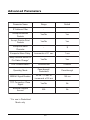
Advanced Parameters
Parame te r Name
Rang e
De fault
IP Ad d re ss Filte r
-
-
Acce p t Bro ad cast
Packe ts
Ye s/No
Ye s
Acce p t Po int-to -Po int
Packe ts
Ye s/No
Ye s
Escap e -to -Me nu
Characte r
-
$
Escap e -to -Me nu De lay
Incre me nts o f 0.1 se c
1 se c
No tify Re mo te No d e s o f
Pin Status Chang e *
Ye s/No
Ye s
Lo st Co mmunicatio n
Co ntinue /Halt
Co ntinue
Op e rating Mo d e
Pass-thro ug h/
Packe tize d
Pass-thro ug h
BREAK Sig nal Duratio n
50 ms - 10 se c in
incre me nts o f 50 ms
100 ms
TCP Co nne ctio n Clo se
Sig nal
Ye s/No
No
Te chnical Sup p o rt
Ac c e s s
N/A
No
* Fo r use in Packe tize d
Mo d e o nly
56
The IP Address Filter parameter allows you filter out packets
received by the Serial Adapter from any IP Address other than
one specified IP Address. You may specify only one IP Address from which to accept messages. The default for this
parameter is to receive packets from any IP Address.
The configuration menu allows you to apply Packet Type
Filters to limit the type of messages the unit receives. You may
chose to filter either Point-to-Point or Broadcast messages. By
default, the Serial Adapter will accept all packet types.
The Escape Parameters option allows you to customize when
the configuration menu will appear by changing the Escape-toMenu Character from “$” and by changing the Escape-toMenu Delay settings to an interval of 0.1 of a second. Note that
when entering a value for the Escape-to-Menu parameter, a value
of 1 corresponds to a delay of 0.1 second. Likewise, a value 10
corresponds to a 1 second delay.
The Escape-to-Menu Delay parameter sets the length of time
which must elapse, with no additional keystrokes, both before
and after the three identical Escape-to-Menu Characters are sent
to the Serial Adapter. By default, the configuration menu
appears when “$$$” is sent to the Serial Adapter and the unit has
not received any characters for 1 second before or after the
receipt of “$$$”.
The Notify Remote Nodes of Pin Status Change parameter is
only relevant when the Serial Adapter is in Packetized mode.
When enabled, the Serial Adapter will pass changes in the status
of the RTS, CTS, DTR, DSR, RI, and CD pins to the remote side
of the connection. This information is not visible to the user.
The Lost Communication parameter allows you to set the
behavior of the Serial Adapter when it is in Pass-through mode
57
and loses communication with its destination unit. You may set
the unit to either reestablish the connection and continue transmissions or to halt communications to provide an alert that the
connection has been lost.
If the Serial Adapter loses communication while set to Continue,
the unit will try to reestablish communication. If the unit loses
communication when set to Halt, the Status LED on the top of
the unit will blink once in a repeating pattern until the unit is
reset.
The Operating Mode parameter allows you to set the Serial
Adapter to either Pass-through or Packetized mode. See Chapter
4 for a detailed discussion of these operating modes.
Some applications use a BREAK signal, sent for a specified
length of time, to control the flow of data between two RS-232
devices. When a pair of Serial Adapters receive a BREAK
command from an attached serial device, the units cannot determine for what length of time the BREAK signal should be sent
to the other serial device. The BREAK Signal Duration parameter allows you to configure the duration of the BREAK signals
the receiving Serial Adapter will transmit to the second RS-232
device when a BREAK command is sent by the first RS-232
device. Note that most applications do not use a BREAK signal
to communicate, but refer to your application’s documentation to
determine if it uses a BREAK signal.
The BREAK signal may be between 50 ms and 10 seconds.
This value is defined in intervals of 50 ms. Within the configuration menu, a value of 1 corresponds to 50 ms and a value of
200 corresponds to 10,000 ms or 10 seconds. By default, the
BREAK signal duration is set to a value of 2, which corresponds
to 100 ms.
58
If you have written, or plan to write, a custom application to
allow communication between the RangeLAN2 Serial Adapter
and an Ethernet device, set the TCP Close Connection Signal
parameter to “Yes.” When this parameter is enabled, the Serial
Adapter will close an existing TCP connection upon receipt of
the “$QUIT” command from a remote workstation.
For more information on the “$QUIT” command and for a
discussion of how to establish communication between a Serial
Adapter and an Ethernet device, see Chapter 3 and Appendix B,
the Serial Adapter TCP/IP Specification.
By default, the TCP Close Connection Signal is disabled and set
to “No.”
The Serial Adapter configuration menu contains several parameters that are not needed for normal operation. A password is
required to enable Technical Support Access to view these
additional parameters.
If you call Proxim Technical Support, they may ask you to
enable the Support parameters, but, in general, you will not need
to view or change these parameters during normal operation.
59
60
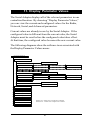
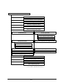
11. Display Parameter Values
The Serial Adapter displays all of the relevant parameters in one
centralized location. By choosing “Display Parameter Values,”
you can view the current and configured values for the Radio,
Network, Serial, and Advanced parameters.
Current values are already in use by the Serial Adapter. If the
configured value is different from the current value, the Serial
Adapter must be reset before the configured value takes effect.
At that time, the configured value becomes the new current value.
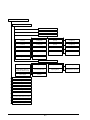
The following diagrams show the software trees associated with
the Display Parameter Values menu:
S e ria l A d a p te r M a in M e n u
D isp la y Pa r a m e te r V a lu e s
R a d io P a ra m e te rs
D o m a in
Channel
S ubchannel
M a ste r/S ta tio n
M a ste r N a m e
R e p e a tin g E n a b le d
M A C O p tim iz e
In a c tivity T im e o u t (se c .)
R o a m in g C o n fig .
R o a m in g E n a b le d
N e tw o rk Pa ra m e te rs
S end M ode
D e stin a tio n Ad d re ss
IP A d d re ss (c u rre n t)
IP A d d re ss (c o n fig u re d )
S u b n e t M a sk
L o c a l Po rt #
R e m o te Po rt #
G a te w a y r IP A d d re ss (c u r re n t)
G a te w a y IP Ad d re ss (c o n fig u re d )
S e ria l P a ra m e te rs
A d va n c e d C o n fig u ra tio n P a ra m e te rs
R e se t P a ra m e te rs to F a c to ry D e fa u lts
R a d io C o n fig u ra tio n M e n u
N e tw o rk C o n fig u ra tio n M e n u
S e ria l C o n fig u ra tio n M e n u
Ad va n c e d C o n fig u ra tio n M e n u
V ie w S ta tistic s
D o w n lo a d N e w S o ftw a re V e rsio n
R e se t th e S e ria l A d a p te r
D o tted Line - V isible w hen configured as a M a ste r
D a shed Line - V isible w he n co nfig ured a s a S tation
E x it to O p e ra tin g M o d e
61
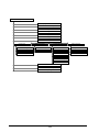
Serial Adapter Main Menu
Display P arameter V alues
R adio Parameters
N etw ork P arameters
S erial P arameters
Baud R ate
(current)
Baud R ate
(configured)
P arity
(current)
P arity
(configured)
# S top Bits
(current)
# S top Bits
(configured)
# Data Bits
(current)
# Data Bits
(configured)
E cho Mode
Max. Line Length
Input T imeout (ms)
Line Delimiters
Generate X ON /X OFF
Recognize X ON/OFF
Generate C T S
Generate D SR
Recognize D T R
Recognize R T S
Adv anced Configuration Parameters
Accept P ackets From
P acket T ypes Accepted
E scape C haracter
E scape D elay (.1 sec)
Notify R emote Nodes of
RS -232 Pin Status C hange
Lost C ommunication
Operating Mode
Break Duration x (50 ms)
Use T CP Connection
Close S ignal
T ech Support Access
E nabled
Reset Parameters to Factory Defaults
Radio Configuration Menu
Netw ork Configuration Menu
Serial C onfiguration Menu
Adv anced Configuration Menu
View Statistics
Dow nload New Softw are Version
Reset the S erial Adapter
Exit to Operating Mode
62
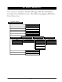
12. View Statistics
You can view statistics about the RangeLAN2 Serial Adapter
from the View Statistics menu. The following diagram illustrates
the software tree:
S erial Ad ap ter M a in M en u
D isp lay Param eter V alu e s
R es et P ara m eters to F ac to ry D e fa u lts
R ad io C o n fig u ratio n M en u
N etw o rk C o n fig u ratio n M en u
Se rial C o n fig u ratio n M en u
Ad van c ed C o n fig u ratio n M en u
View S tatistic s
S erial Erro rs
Pa cketiz ed M o d e
T C P/IP Statis tics
R ad io Statistic s
F ra m in g
P ack ets Acc ep ted
U D P Pac kets S en t
Syn c h ro n ized T o
Parity
P ack et Erro rs
U D P Pac kets R eceived
Pa ckets T ra n sm itted
T C P P ack ets S en t
Pa ckets R ec eive d
O v erru n
T C P P ack ets R e ceived
T C P C o n n ectio n s O p en e d
T C P C o n n ectio n s C lo sed
D o w n lo ad N ew So ftw are V ers io n
R es et th e S erial Ad ap ter
Ex it to O p eratin g M o d e
63
Serial Errors Statistics
This category displays the number of errors occurring in the serial
interface of the Serial Adapter during operation.
The Serial Adapter will record the number of framing errors that
occur when a character is received over the serial line without a
valid stop bit.
A parity error occurs when the parity check (i.e., even, odd, mark,
or space) failed for a received character.
An overrun error occurs when the serial chip’s receive buffer
overflows due to an excessive number of received characters.
Packetized Mode Statistics
This category displays the number of packets accepted and the
number of errors encountered by the Serial Adapter while operating in Packetized mode.
TCP/IP Statistics
This category displays information regarding the number of TCP
and UDP packets sent and received by the Serial Adapter and the
number of TCP connections opened and closed.
Radio Statistics
This category displays information about the packets sent and
received through the radio interface and the Serial Adapter’s
sychronization status with a RangeLAN2 Master.
64
13. Performance Hints
This section provides the user with ideas for how to increase
performance with Proxim wireless products.
Microwave Ovens
Microwave ovens operate in the same frequency band as
RangeLAN2 products. Therefore, if you use a microwave within
range of RangeLAN2 equipment, you may notice network
performance degradation. However, both your microwave and
your RangeLAN2 network will continue to function.
Range
Every environment is unique with different obstacles, barriers,
materials, etc. and, therefore, it is difficult to determine the exact
range that will be achieved without testing. Proxim has developed some guidelines to estimate the range that users will see
when the RangeLAN2 7910 Serial Adapter is installed in their
facility, but there are no hard and fast specifications. Note that the
RangeLAN2 7911 Serial Adapter will have greater range.
Radio signals may reflect off of some obstacles or be absorbed by
others depending on their construction. For example, with two
RangeLAN2 radios, you may achieve up to 1000' in open space
outdoors where the two antennas are line of sight, meaning they
see each other with no obstacles. However, the same two units
will only achieve up to 500' of range when they have to travel
through the cubicles usually used in modern offices. If there are
office walls to penetrate, the signal range may decrease even
further to up to 300'.
If you are interested in antenna options, contact your Proxim Sales
Representative about antenna kits.
65
Proper antenna placement can help improve range. Here are
some guidelines:
❑ The antenna should be placed in a vertical position.
❑ Do not place a sheet of metal (like a filing cabinet)
between two antennas.
❑ Two antennas that are communicating should be in the
same plane. For example, do not lie one antenna on its
side and have its partner standing upright.
66
14. Troubleshooting
The RangeLAN2 791x Serial Adapter is designed to be very easy
to install and operate. If you do experience difficulties, however,
use the information in this chapter to help diagnose and solve the
problem. If you cannot resolve the problem, contact Proxim, as
described in Appendix G, “How to Reach Technical Support.”
How to Obtain Help with Your Installation
If you require assistance to install your Serial Adapter, Proxim can
put you in touch with a RangeLAN2 Reseller in your area. The
reseller is an expert in the design, installation, and maintenance of
wireless communication products and will be able to examine
your needs and recommend the most cost-effective wireless
solution for your needs. For the location of the RangeLAN2
reseller nearest you, contact Proxim at 800-229-1630 and ask for
the Sales Department.
LED Error Codes
The Status LED, located on the top of the Serial Adapter, will
blink red in a repeating pattern to indicate an error has occurred.
If you see any of the repeating flashing sequences listed below,
first attempt to reset the Serial Adapter. If the flashing sequence
persists after you have reset the unit, make a note of which of the
above patterns you see and call Proxim Technical Support.
The Status LED will flash red to indicate the following errors:
1 brief flash: There was a buffer overflow and the buffers
were flushed; no reset is required
1 blink : Lost communication with the destination
2 blinks: Memory check failed
67
3 blinks: Software error
4 blinks: Failed to initialize the radio
5 blinks: Memory full
6 blinks: Miscellaneous error
7 blinks: Failed to initialize the TCP/IP stack
Commonly Asked
Technical Support Questions
Pro b le m/Symp to m Que stio n
Po ssib le So lutio n/Answe r
Chap te r in Use r' s
Guid e
The Se rial Ad ap te rs are no t
co mmunicating .
1. Che ck to e nsure that the Do main
Switch is no t se t to 9 o n e ithe r unit.
2. Ve rify that ne ithe r unit is se t in the
co nfig uratio n me nu.
3. Ve rify that yo u have the same
Do main and Se curity ID se t fo r b o th
units.
4. Ensure that the re is o ne and
o nly o ne Maste r se t in yo ur wire le ss
to p o lo g y.
5. Ve rify that e ach Se rial Ad ap te r
has the o the r unit' s IP Ad d re ss se t
as its De stinatio n IP Ad d re ss in the
Ne two rk Co nfig uratio n Me nu.
3, 5, 7, 8
One o f my Se rial Ad ap te rs
will no t acce p t b ro ad cast
p acke ts.
1. Ve rify that yo u d o no t have
Packe t Typ e Filte rs se t to re ce ive
o nly p o int-to -p o int p acke ts.
2. Ensure that yo u d o no t have the
IP Ad d re ss Filte r se t.
3. The Se rial Ad ap te r can no t
b ro ad cast thro ug h a g ate way o r
ro ute r.
8, 10
Will the Se rial Ad ap te r
co mmunicate with Pro xim' s
o the r RS-232 re p lace me nt
d e vice s, like the Pro xLink?
The Rang e LAN2 Se rial Ad ap te r will
o nly co mmunicate with o the r
Rang e LAN2 Se rial Ad ap te rs and
o the r Rang e LAN2 p ro d ucts; it will no t
co mmunicate with the 900Mhz
Pro xLink family o f p ro d ucts.
1
68
Pro b le m/Symp to m Que stio n
Po ssib le So lutio n/Answe r
Chap te r in Use r' s
Guid e
I can' t b ring up the
Co nfig uratio n Me nu.
1. Ve rify that yo ur te rminal se tting s
match tho se se t o n the Se rial
Ad ap te r.
2. Ensure that yo u are using a RS232 cab le to co nne ct the Se rial
Ad ap te r that co nfo rms to the Se rial
Ad ap te r Pin Sp e cificatio n as sho wn
in Chap te r 5.
3. Be sure to o nly typ e o nly thre e
"$" symb o ls in rap id succe ssio n.
Typ ing two o r fo ur characte rs will no t
b ring up the me nu.
4. Chang ing the Do main Switch to 9
will b ring up the co nfig uratio n me nu
at 9600 b p s 8N1.
5, 6, 7
The thro ug hp ut se e ms slo w.
To achie ve maximum thro ug hp ut,
ve rify yo ur ante nnas are we ll-p lace d ,
no t b e hind me tal, and the re are no t
to o many o b stacle s.
13
Why are the re 16 Do main
cho ice s in the co nfig uratio n
me nu b ut o nly 10 o n the
Do main ro tary switch?
The ro tary switche s are d e sig ne d to
allo w use rs to co nfig ure the Se rial
Ad ap te rs witho ut running the
co nfig uratio n so ftware . Do mains 0-8
o n the d ial co rre sp o nd to Do mains 08 in the so ftware co nfig uratio n me nu.
If yo ur wire le ss e nviro nme nt re q uire s
mo re than 9 Do mains, yo u sho uld
use the so ftware co nfig uratio n to o l to
se t a unit to Do mains 9-15. Do no t
use Do main 9 o n the Do main Switch
in no rmal o p e ratio n b e cause it will
b ring up the so ftware co nfig uratio n
me nu.
5, 7
Why d o all o f the characte rs
ap p e ar twice o n my
co mp ute r scre e n?
Yo u may have se t o ne o r mo re
Se rial Ad ap te rs to Simp le o r Te rminal
Echo Mo d e . Che ck yo ur units to
e nsure that Echo Mo d e is se t to
No ne .
9
69
A. Packetized Mode Specification
Overview
The purpose of the Serial Adapter is to accept information from a
serial line and transmit it reliably via radio to another RangeLAN2
station, or to a wired station through a RangeLAN2 Access Point.
Serial Adapters receiving information transfer it to an external
computer (“External Computer”) via their own serial lines. The
Serial Adapter contains a sophisticated radio protocol which
permits orderly and reliable flow of information over the radio
network in the presence of an unknown (and possibly varying)
population of RangeLAN2 units.
This document does not explore the details of the radio protocol.
Instead, it focuses on the protocol used to exchange information
with an External Computer via the Serial Adapter’s serial line.
Pass-through Versus Packetized Mode
On the surface, it would appear that the radio protocol used by
Serial Adapters to communicate with one another is the only
protocol necessary. Information passing into the serial line should
simply be captured by the Serial Adapter, and forwarded to the
destination Serial Adapter using the radio protocols built into the
Serial Adapter. Each Serial Adapter should transparently forward
any information coming into its serial line onto the radio network.
The serial line would effectively have no protocol; all data would
simply be passed through to the radio network.
Proxim does provide a mode in the Serial Adapter which behaves
in this way, called the Pass-through mode. Because the Passthrough mode does not require data sent into its serial line to be
formatted in any way, it is an excellent choice for applications
where the Serial Adapter is used to replace a wire or in applica70
tions where developing special software to interact with the Serial
Adapter is undesirable.
For some applications, the Pass-through mode of operation is not
ideal. For example, because the Pass-through Serial Adapter
takes all information arriving at its serial line as data to be sent out
over the radio network, it is not possible to change the Serial
Adapter’s configuration on the fly by sending it commands over
the serial line.
For the External Computer to be able to send both data and
commands to the Serial Adapter, both the Serial Adapter and the
External Computer must agree on some rules of order for distinguishing data packets from command packets. Proxim has defined a simple serial protocol which performs this function. This
protocol is incorporated into the packetized mode of the firmware.
The remainder of this document is devoted to an explanation of
the Packetized mode serial protocol.
The figure below illustrates the protocol architecture of the
Packetized mode.
MCP
(Modem Command
Protocol)
PPX-1
(Proxim Packet Exchange)
RS-232
71
The Modem Command Protocol (MCP) is an application layer
protocol by which an External computer may exchange commands, status information, and data with the Serial Adapter over
the Serial Adapter’s RS-232 serial line. Since the protocol is an
application layer protocol, it contains no provision for error
recovery over the serial line. This problem of error recovery is a
layer 2 problem and is handled by the Proxim layer 2 serial
protocol, the PPX-1.
The MCP protocol consists of a set of commands which cause the
Serial Adapter to transmit data, change an operating parameter, or
respond with status information. The MCP protocol is conveyed
over the serial line using the PPX-1 layer two protocol. The
details of the PPX-1 protocol are unrelated to the details of the
MCP protocol.
The PPX-1 protocol used by the Serial Adapter is very similar to
what is used by Proxim’s 900 MHz ProxLink. The MCP protocol is designed to be compatible with the 900 MHz product
wherever possible, but because the 2.4 GHz Serial Adapter
contains additional features, uses a different radio, and handles
networking differently, there are significant changes.
PPX-1 is a very simple, unacknowledged protocol. No provision
is made within PPX-1 for error correction (retries, etc). PPX-1
does provide simple error detection through the use of a check
code. The most significant attribute of PPX-1 is it simplicity.
The table below summarizes the features of the PPX-1 layer 2
protocol:
Error Detection
Error Correction
Suitable Applications
16-bit Checksum
None
Serial line to Serial Adapter is short
Higher layer error correcting
protocol is in use above PPX-1
72
PPX-1 Protocol
The following is the format of the PPX-1 packet:
BYTE
SOH
BYTE
BYTE
BYTE
LEN H
LEN L
HEADER
CHECK
BYTES
DATA
BYTE
CHECKSUM H
CHECKSUM L
BYTE
;Start of header for synchronization
(ASCII 01H)
;High byte of length
;Low byte of length
;= NOT(LEN L) +
;NOT(LEN H), this is an
; arithmetic sum
;This is where the MCP COMM;AND is contained (see section 3)
;16 bit check sum of data
Note that the LEN field is the length of the DATA section, not
including the CHECKSUM field.
The purpose of the header is to make frame synchronization
easier. In asynchronous communications where the data field may
have any ASCII value, this is a difficult problem. The HEADER
CHECK field is intended to provide a fairly secure way of making sure that a header has actually been found.
The maximum permissible packet length is 1456 bytes (not
including the header and checksum).
73
Modem Command Protocol (MCP)
This section describes the Modem Command Protocol. All of the
commands which the Serial Adapter will accept are listed below.
Each command begins with a command byte which tells the
Serial Adapter which command the message contains.
Some commands cause the Serial Adapter to produce a response
packet at a later time. The format of all possible Serial Adapter
responses is listed in the section entitled “MCP Response from the
Serial Adapter.” The first byte of each response generated by the
Serial Adapter also contains a “command” byte which the External Computer can use to distinguish different responses from each
other.
When the External Computer sends a command to the Serial
Adapter which will cause the Serial Adapter to generate a response, the External Computer need not wait until the response is
sent by the Serial Adapter before sending the Serial Adapter
another command. In other words, the External Computer may
have multiple commands outstanding to the Serial Adapter at
once. If the Serial Adapter has been sent multiple commands, it
will not, in general, respond to the commands in the same order
that they are received. The reason for this is that some commands
take much longer to execute than others. The Serial Adapter
attempts to respond to each command as rapidly as possible.
If the External Computer elects to take advantage of this feature,
the software in the External Computer must be able to unambiguously associate responses with their corresponding commands.
The Serial Adapter Command Protocol contains a feature that
makes this process easier.
Each Serial Adapter command for which there is a Serial Adapter
response contains an extra field known as the seqno field. When
74
the External Computer creates a command packet, it should place
a unique number (from 0 to 127) into the seqno field of the
packet. When the Serial Adapter later generates a response to that
packet, it will place this same value in the seqno field of the
response. In this way, the External Computer can match responses with commands.
MCP Command Messages to the Serial Adapter
This section describes each of the messages which may be sent to
the Serial Adapter via its RS-232 serial line by an External Computer. The first byte of each command specifies the command that
the Serial Adapter is to perform. It is followed by data bytes
which are actually arguments to the command. The data format is
8 data bits, no parity, 1 stop bit.
Transmit Data Packet
Purpose: To send a data message over the radio to the specified
Serial Adapter.
Response Expected from Serial Adapter: “Status Indication of
Transmitted Packet”
Message Format:
BYTE
BYTE
BYTE
BYTE
BYTE
BYTE
BYTE
BYTE
BYTES
command (ASCII ‘T’, 54H)
seqno
len H
; Length of data field below
len L
destaddr H
destaddr 3
destaddr 2
destaddr L
data
75
The four byte address field is the IP address of the destination
node. Broadcast addresses (for example, x.y.z.255) can also be
used.
Request Radio Signal Strengths
Purpose: To request the Serial Adapter to measure the strength of
RF energy on its current radio channel and report the signal
strength. The signal strength is reported as an 8-bit value from
00H (minimum signal value) to FFH (maximum signal value).
Response Expected from Serial Adapter = “Signal Strength
Report”
Message Format:
BYTE
BYTE
command (ASCII ‘R’, 52H)
seqno
Request Serial Adapter Version
Purpose: To request the physical address and version number of
the Serial Adapter. The address is reported as a 4 byte value, only
the lower 28 bits of which are meaningful. The version number is
reported as a 7 character string.
Response Expected from Serial Adapter = “Serial Adapter Version Report”
Message Format:
BYTE
BYTE
command (ASCII ‘V’, 56H)
seqno
76
Go To Standby
Purpose: The purpose of this command is to place the Serial
Adapter in Standby mode in order to conserve current. For this
command to work properly, the RTS line at the Serial Adapters
serial connector must be inactive. The Serial Adapter can be
removed from Standby mode by asserting the RTS line.
Response Expected from Serial Adapter = None.
Message format:
BYTE
command (ASCII ‘G’, 47H)
Initialize Serial Adapter
Purpose: To initialize the Serial Adapter.
Response Expected from Serial Adapter: “Initialization Confirmation”
Message Format:
BYTE
BYTE
command (ASCII ‘I’, 49H)
seqno
Set Radio Channel
Purpose : To set the Serial Adapter’s radio channel.
Response Expected from Serial Adapter: “Radio Channel Confirmation”
77
Message Format:
BYTE
BYTE
BYTE
command (ASCII ‘C’, 43H)
seqno
Radio Channel (1 to 15)
Set Network Subchannel
Purpose: To set the subchannel of the Serial Adapter’s network
protocol.
Response Expected from Serial Adapter: “Subchannel Confirmation”
Message Format:
BYTE
BYTE
BYTE
command (ASCII ‘S’, 53H)
seqno
subchannel (1 to 15)
Set Baud Rate
Purpose: To set the baud rate of the Serial Adapter serial line.
When the command is received, the Serial Adapter generates the
Baud Rate Confirmation message. After that, it then switches to
the new baud rate.
Response Expected from Serial Adapter: “Baud Rate Confirmation”
Message Format:
BYTE
BYTE
BYTE
command (ASCII ‘B’, 42H)
seqno
baudrate (HEX 02 through 0A)
78
The meaning of the baud rate argument is as follows:
Value of
baudrate field Baud rate
2
300
3
1200
4
2400
5
4800
6
9600
7
19200
8
38400
9
57600
A
115200
Station Search
Purpose: To send a broadcast message asking any station receiving the message to reply with its IP address.
Response Expected from Serial Adapter: “Station Search Reply”
BYTE
command (ASCII ‘A’, 41H)
Get RS-232 Pin Status
Purpose: To get the pin status of the specified destination node.
Response Expected from Serial Adapter: “RS-232 Pin Status
Reply”
BYTE
BYTE
4 BYTES
command (ASCII ‘P’, 50H)
seqno
IP address of remote node, 0.0.0.0 acceptable for default destination.
79
Call up Configuration Menu
Purpose: To invoke the Serial Adapter configuration menu from
packetized mode.
Response Expected from Serial Adapter: None
BYTE
command (ASCII ‘M’, 4DH)
Override RangeLAN2 Parameters
Purpose: To allow a Serial Adapter application to set the Domain,
Security ID, and MASTER/STATION status. The new values
will not be written to EEPROM, and therefore will go away when
the Serial Adapter is powered off. The Serial Adapter must be reinitialized for the changes to take effect.
Response Expected from Serial Adapter: “RangeLAN2 Parameter Confirmation”
BYTE
BYTE
BYTE
BYTE
20 BYTES
command (ASCII ‘O’, 4FH)
seqno
Function number:
1= Set Domain
2= Set Security ID
3= Set MASTER/STATION
data (functions 1 and 3 only)
Function 1: Domain number (0-15)
Function 3: 0= MASTER,
1= STATION
data (Function 2 only)
Security ID string. If the string is less
than 20 bytes, pad with NULL characters.
80
MCP Responses From Serial Adapter
This section describes the format of MCP response messages
passed from the Serial Adapter to an External Computer.
Data Packet Received
Purpose: This is the message used by the Serial Adapter to deliver
packets to the External Computer which have been received by
the Serial Adapter over the radio.
Message Format:
BYTE
BYTE
BYTE
BYTE
BYTE
BYTE
BYTE
BYTE
BYTE
BYTES
response (ASCII ‘d’, 64H)
rssi
;Radio signal strength of received
:packet
pinstat
;RS-232 pin status of sending node
len H
;Length of the user message
len L
srcaddr H
;IP Address of source
srcaddr 3
srcaddr 2
srcaddr L
user message
Status Indication of Transmitted Packet
Purpose: This message informs the External Computer of the
status of the most recent data message sent to the Serial Adapter
with the Transmit Data Packet command. The response contains a
duplicate of the sequence number provided in the original Transmit Data Packet message, as well as the length and destination
address. In addition, a StatusInd code is provided which indicates whether the message was sent successfully to the TCP/IP
stack or not.
81
The StatusInd field does not show whether the destination node
has received the message.
Message Format:
BYTE
BYTE
BYTE
BYTE
BYTE
BYTE
BYTE
BYTE
BYTE
response (ASCII ‘t’, 74H)
seqno
(from original command)
len H
(from original command)
len L
(from original command)
destaddr H
(from original command)
destaddr 3
(from original command)
destaddr 2
(from original command)
destaddr L
(from original command)
StatusInd
The valid values of the StatusInd field are as follows:
00H: Successful Transmission to the TCP/IP stack
01H: Transmission Error
Signal Strength Report
Purpose: This packet is generated by the Serial Adapter in response to a Request Radio Signal Strength command. The packet
contains the signal strength value for the Serial Adapter’s current
radio channel. The signal strength value range from 00H to FFH.
A value of FFH signifies maximum signal strength.
Message Format:
BYTE
BYTE
BYTE
response (ASCII ‘r’, 72H)
seqno (from original command)
Signal strength on current channel
82
Serial Adapter Version Report
Purpose: This packet is generated by the Serial Adapter in response to a Request Serial Adapter Version command. The
packet contains the 4-byte IP address of the Serial Adapter, along
with the Version string and a code indicating the radio type.
Message Format:
BYTE
BYTE
BYTE
BYTE
BYTE
BYTE
7 BYTES
BYTE
response (ASCII ‘v’, 76H)
seqno (from original command)
IPaddr H
;Serial Adapter’s IP Address
IPaddr 3
IPaddr 2
IPaddr L
string (7 byte ROM version number string)
Radio Type(03= RangeLAN2 Extended Range)
Standby Confirmation
Purpose: This packet is generated by the Serial Adapter after a
Go To Standby command is received from the External Computer. Immediately after generating this response, the Serial
Adapter enters standby mode. The Serial Adapter can only be
removed from standby mode by asserting the RTS input signal.
Message Format:
BYTE
response (ASCII ‘g’, 67H)
Initialization Confirmation
Purpose: This packet is generated by the Serial Adapter after an
Initialize Serial Adapter command is received from the External
Computer. For convenience, the packet contains the physical
address of the Serial Adapter.
83
Message Format:
BYTE
BYTE
BYTE
BYTE
BYTE
BYTE
7 BYTES
BYTE
response (ASCII ‘i’, 69H)
seqno (from original command)
IPaddr H (Serial Adapter’s IP Address)
IPaddr 3
IPaddr 2
IPaddr L
string (7 byte ROM version number string)
Radio Type: 03= RangeLAN2 Extended Range,
04= RangeLAN2 Extended Range,
100mW (Europe)
Radio Channel Confirmation
Purpose: This packet is generated by the Serial Adapter after a Set
Radio Channel command is received from the External Computer.
The radio channel provided in the original command is included
in the response.
Message Format:
BYTE
BYTE
BYTE
response (ASCII ‘c’, 63H)
seqno (from original command)
Radio Channel (1 to 15, from original
command)
Subchannel Confirmation
Purpose: This packet is generated by the Serial Adapter after a Set
Network Subchannel command is received from the External
Computer. The subchannel provided in the original command is
included in the response.
84
Message Format:
BYTE
BYTE
BYTE
response (ASCII ‘s’, 73H)
seqno (from original command)
subchannel (1 to 15, from original com
mand)
Baud Rate Confirmation
Purpose: This message is sent after a Set Baud Rate command is
received by the Serial Adapter. Note that this message is sent at
the old baud rate. The Serial Adapter switches to the new baud
rate immediately after this response is sent.
Message Format:
BYTE
BYTE
BYTE
response (ASCII ‘b’, 62H)
seqno (from original command)
baud rate (02H to 0AH, from original
command)
Station Search Reply
BYTE
4 BYTES
response (ASCII ‘a’, 61H)
Serial number (IP address) of responding
station
RangeLAN2 Parameter Confirmation
BYTE
BYTE
BYTE
BYTE
response (ASCII ‘o’, 6FH)
seqno
Function number
status
0= success
1= error
85
RS-232 Pin Status Reply
BYTE
BYTE
BYTE
4 BYTES
BYTE
response (ASCII ‘p’, 70H)
seqno
status
0= success
1= error
IP address of remote node
pin status
The pin status byte b will consist of the following fields:
b0: 1 if DTR is asserted
b1: 1 if DSR is asserted
b2: 1 if RTS is asserted
b3: 1 if CTS is asserted
b4: 1 if CD is asserted
b5: 1 if the destination has sent a BREAK
b6: reserved and always 0
b7: reserved and always 0
86
B. Serial Adapter TCP/IP Specification
The fundamental obstacle to allowing a Serial Adapter to communicate with a wired workstation is that the two units communicate
in different ways. To address this discrepancy, the user must have
a custom application programmed by someone familiar with TCP/
IP networks. This custom TCP/IP program will allow the wired
workstation to communicate in the same manner as the Serial
Adapter.
Below is a broad overview of the steps necessary to establish
communications between a Serial Adapter and a station on a
wired Ethernet network.
This procedure is written for the case where one Serial Adapter is
talking to a workstation on an Ethernet network; it can easily be
expanded to have multiple Serial Adapters communicating with a
single wired workstation.
1. Connect a RangeLAN2 Access Point to the wired network.
2. Set the Serial Adapter as a Station and have it synchronize to
the Access Point by setting the Domain and Security ID on the
Serial Adapter to match the values used by the Access Point.
3. Ensure that the wired workstation is running the TCP/IP
protocol.
4. The user must write a custom program to run on the wired
workstation in order to communicate with the Serial Adapter.
This program must use a library that interfaces with the TCP/IP
protocol to send and receive data.
For example, Windows Sockets is the most commonly used
interface on a PC and is a standard part of Windows 95. Note
87
that Windows Sockets programs require a compiler, such as
Visual C++, in order to be executed. On UNIX machines,
Berkeley Sockets is available on most of the common platforms.
5. The data sent to the Serial Adapter must be formatted appropriately. A four-byte header precedes the user data that is sent.
The contents of the four header bytes is as follows:
BYTE 1: Packet type
0= point-to-point (UDP or TCP), or 1= broadcast
BYTES 2 and 3: Packet length.
This is the length of the user data to be sent in this packet. The
allowable range of lengths is 1-1456 bytes. The length bytes are
arranged in network byte order.
BYTE 4: This byte is used to communicate RS-232 pin status to
other Serial Adapters. Use a value of 0F (Hex) to ensure that the
wired workstation and the Serial Adapter will communicate
without interruption.
The pin status byte includes the following information:
Bit 0 is set if DTR is asserted on the sending side; set this to a
value of 1 so that the Ethernet workstation will appear to have
DTR asserted.
Bit 1 is set if DSR is asserted on the sending side.
Bit 2 is set if RTS is asserted on the sending side; set this to a
value of 1 so that the Ethernet workstation will appear to have
RTS asserted.
Bit 3 is set if CTS is asserted on the sending side.
88
Bit 4 is set if CD is asserted on the sending side.
Bit 5 is set if the sending host has sent a BREAK; this bit should
be set to 0.
Bit 6: Reserved and always set to 0.
Bit 7: Reserved and always set to 0.
Messages received from the Serial Adapter will contain the fourbyte header before the actual data. Note that the header size and
format is the same whether the Serial Adapter is in Pass-through
or Packetized mode.
6. The port numbers, IP Address, Destination Address, and Send
Mode need to be set up on the Serial Adapter to match what your
program on the wired workstation is using.
The Remote Port Number must match the port number on which
your workstation program is listening.
The IP Address and Local Port Number must match the port
number and address to which your workstation program is sending.
If the Serial Adapter is in Pass-through mode, the destination
address must be set to the IP address of the wired workstation. If
the Serial Adapter is in Packetized mode, your Packetized mode
program must set the Destination Address of the data packets it
sends to the IP address of the wired workstation.
The Send mode of the Serial Adapter must match the protocol that
your workstation program is using to receive messages (TCP or
UDP).
89
7. The Default Gateway Address and Subnet Mask parameters
on the Serial Adapter must be set to the appropriate values for
your network. See your Network Administrator for details.
8. It is also possible to do a station search from a wired workstation to determine the IP Address of any Serial Adapters within
range. The station search is a one byte packet (value of the byte is
2), sent as a UDP broadcast.
Each Serial Adapter that receives the search packet will send the
following response:
1 BYTE:
packet type (= 3)
4 BYTES:
IP address of responding Serial Adapter
The response is sent by the Serial Adapter using a directed UDP
message.
Many reference books are available on Sockets programming,
both for Windows and UNIX. Suggested reference books include:
Comer, Douglas E., Internetworking with TCP/IP, Vol. 1-3, 3rd
ed. Prentice-Hall, Englewood Cliffs, New Jersey, 1995.
Stevens, W. Richard, TCP/IP Illustrated, Vol. 1-3, AddisonWesley, Reading, Mass., 1994.
Stevens, W. Richard, UNIX Network Programming: Networking
APIs: Sockets and XTI, 2nd ed., Prentice-Hall, Englewood Cliffs,
New Jersey, 1997.
90
Sample TCP/IP Communication Programs
On the following pages are four pieces of sample code written in
Berkeley Sockets as an example of the type of custom code which
must be written so that the Serial Adapter can communicate with
nodes on an Ethernet network.
Note:
If your custom program makes use of the “$QUIT”
command so that the Serial Adapter will close open TCP
connections, set the TCP Close Connection Signal parameter to “Yes” within the Serial Adapter’s Advanced
Configuration Menu.
Sample TCP Receive Program
1
2
3
4
5
6
7
8
9
10
11
12
13
14
15
16
17
18
19
20
21
22
/*******************************************************
* tcprecv.c
* Receives messages from one or more Serial Adapters using TCP
*
*******************************************************/
#include <sys/types.h>
#include <sys/socket.h>
#include <netinet/in.h>
#include <netdb.h>
#include <stdio.h>
#define TRUE 1
main()
{
int i, sock, length;
struct sockaddr_in server;
int msgsock;
char buf[1024];
int rval;
FILE *logfile;
91
23
24
25
26
27
28
29
30
31
32
33
34
35
36
37
38
39
40
41
42
43
44
45
46
47
48
49
50
51
52
53
54
55
56
57
58
59
60
61
62
63
64
/* Open the log file */
logfile= fopen(“proxlink.log”, “wb”);
if (!logfile) {
printf(“Error: Couldn’t open log file\n”);
exit(1);
}
/* Create socket */
sock= socket(AF_INET, SOCK_STREAM, 0);
if (sock < 0) {
perror(“opening stream socket”);
exit(2);
}
/* Create a name with wildcards */
server.sin_family= AF_INET;
server.sin_addr.s_addr= INADDR_ANY;
server.sin_port= 0;
if (bind(sock, (struct sockaddr *)&server, sizeof(server)) < 0) {
perror(“binding stream socket”);
exit(3);
}
/* Find assigned port number and print it out */
length= sizeof(server);
if (getsockname(sock, (struct sockaddr *)&server, &length) < 0) {
perror(“getting socket name”);
exit(4);
}
printf(“Socket port #%d\n”, ntohs(server.sin_port));
/* Start accepting connections. Listen() will return when it
determines that a remote machine is trying to open a
connection. The second parameter to listen() is a queue
length, which is the maximum number of pending connections
allowed on that socket at any given time.
*/
do {
listen(sock, 5);
92
65
/* Establish the TCP connection. Accept() returns a new
66
socket number for the connection, allowing listen() to
67
(if desired) continue to listen on the old socket.
68
69
Parameters to accept() are: the socket that the
70
previous listen() call was using, a sockaddr structure,
71
and the length of the sockaddr structure. The second
72
and third parameters are zero here, but can be used to
73
get the IP address and port number of the remote end of
74
the connection. */
75
msgsock= accept(sock, (struct sockaddr *)0, (int *)0);
76
if (msgsock==-1) {
77
perror(“accept”);
78
}
79
else do {
80
memset(buf, 0, sizeof(buf));
81
if ((rval= read(msgsock, buf, 1024)) < 0)
82
{
83
perror(“reading stream message”);
84
exit(5);
85
}
86
else if (rval==0) {
87
printf(“Read zero bytes. Exiting...\n”);
88
exit(6);
89
}
90
else {
91
/* Print out data on screen and log it to the logfile.
92
Note we are skipping the Serial Adapter header bytes. */
93
printf(“Read %d bytes\n”, rval);
94
buf[rval]= ‘\0’;
95
if (rval > 4)
96
printf(“Data: —> %s\n”, buf+4);
97
for (i= 0; i< rval; i++)
98
fputc(*(buf+i), logfile);
99
fclose(logfile);
100
logfile= fopen(“proxlink.log”, “ab”);
101
}
102
} while (TRUE);
103
104
} while (TRUE);
105 }
93
Sample TCP Send Program
1
/*******************************************************
2 * tcpsend.c
3 * Sends a message to a Serial Adapter using TCP
4 *
5
*******************************************************/
6
7 #include <sys/types.h>
8 #include <sys/socket.h>
9 #include <netinet/in.h>
10 #include <netdb.h>
11 #include <stdio.h>
12
13 #define DATA “Half a league, half a league...”
14 #define DATA1 0
15
16 main(argc, argv)
17 int argc;
18 char *argv[];
19 {
20
int sock;
21
short dataLength;
22
struct sockaddr_in server;
23
struct hostent *hp, *gethostbyname();
24
char buf[1024];
25
26
if (argc < 3) {
27
printf(“Usage: tcpsend hostname port#\n”);
28
exit(3);
29
}
30
31
/* Create socket. */
32 sock= socket(AF_INET, SOCK_STREAM, 0);
33
if (sock < 0) {
34
perror(“opening stream socket”);
35
exit(1);
36
}
37
38
/* Connect socket using name specified on command line */
39 server.sin_family= AF_INET;
94
40
hp= gethostbyname(argv[1]);
41
if (hp==0) {
42
fprintf(stderr, “%s: Unknown host\n”, argv[1]);
43
exit(2);
44
}
45
memcpy( (char *)&server.sin_addr, (char *)hp->h_addr, hp-h_length);
46
server.sin_port= htons(atoi(argv[2]));
47
48
/* Use the connect() socket call to initiate a TCP connection with
49
the remote machine. */
50
printf(“Connecting...\n”);
51
if (connect(sock, (struct sockaddr *)&server, sizeof(server)) < 0 ) {
52
perror(“Connecting stream socket”);
53
exit(1);
54
}
55
printf(“Connected.\n”);
56
57
/* Construct message, including Serial Adapter header bytes */
58 buf[0]= DATA1;
59
buf[3]= 0xf0;
60
dataLength= strlen(DATA);
61
memcpy(&buf[1], &(htons(dataLength)), sizeof(short));
62 strcpy(&buf[4], DATA);
63
printf(“%s\n”, &buf[4]);
64
65
/* Send message */
66
if(write (sock, buf, dataLength+4) < 0)
67
perror(“Sending stream message”);
68
69
/* Send $QUIT string to the serial adapter to tell it to close its
70
side of the TCP connection. */
71
dataLength= 5;
72
memcpy(&buf[1], &(htons(dataLength)), sizeof(short));
73 memcpy(&buf[4], “$QUIT”, 5);
74
if(write (sock, buf, dataLength+4) < 0)
75
perror(“Sending $QUIT message”);
76
77
close(sock);
78
exit(0);
79
80 }
95
Sample UDP Receive Program
1
2
3
4
5
6
7
8
9
10
11
12
13
14
15
16
17
18
19
20
21
22
23
24
25
26
27
28
29
30
31
32
33
34
35
36
37
38
39
40
/********************************************************
* udprecv.c
* Receives a series of messages from a Serial Adapter using UDP.
*
*******************************************************/
#include <sys/types.h>
#include <sys/socket.h>
#include <netinet/in.h>
#include <stdio.h>
main()
{
int sock, length, nbytes;
struct sockaddr_in name;
char buf[1024];
FILE *logfile;
/* Open the log file */
logfile= fopen(“proxlink.log”, “wb”);
if (!logfile) {
printf(“Error: Couldn’t open log file\n”);
exit(4);
}
/* Create socket from which to read */
sock= socket(AF_INET, SOCK_DGRAM, 0);
if (sock < 0) {
perror(“opening datagram socket”);
exit(1);
}
/* Create a name with “wildcards”: The machine will assign its
IP address and a port number. */
name.sin_family= AF_INET;
name.sin_addr.s_addr= INADDR_ANY;
name.sin_port= 0;
/* The bind() call associates a local IP address and port number
with the socket */
96
41
if (bind(sock, (struct sockaddr *)&name, sizeof(name)) < 0) {
42
perror(“binding datagram socket”);
43
exit(1);
44
}
45
46
/* Find assigned port value and print it out. Getsockname() gets
47
the local IP address and port number associated with a socket. */
48
length= sizeof(name);
49
if (getsockname(sock, (struct sockaddr *)&name, &length) < 0) {
50
perror(“getting socket name”);
51
exit(1);
52
}
53
54
printf(“Socket port #%d\n”, ntohs(name.sin_port));
55
56
while(1) {
57
/* Read from the socket */
58
if ((nbytes= read(sock, buf, 1024)) < 0) {
59
perror(“Receiving datagram packet”);
60
exit(2);
61
}
62
/* Print data to screen, not including Serial Adapter header */
63
buf[nbytes]= ‘\0’;
64
printf(“Data: —> %s\n”, buf+4);
65
}
66
67 }
Sample UDP Send Program
1
/********************************************************
2 * udpsend.c
3 * Sends a series of messages to a Serial Adapter using UDP.
4
*******************************************************/
5
6
#include <sys/types.h>
7
#include <sys/socket.h>
8
#include <netinet/in.h>
9
#include <netdb.h>
10 #include <stdio.h>
11
12 #define DATA “The sea is calm, the tide is full...”
97
13
14
15
16
17
18
19
20
21
22
23
24
25
26
27
28
29
30
31
32
33
34
35
36
37
38
39
40
41
42
43
44
45
46
47
48
49
50
51
52
53
54
#define DATA1 0
main(argc, argv)
int argc;
char *argv[];
{
int i, sock;
short dataLength;
short networkDataLength;
long npackets= 0;
char buf[1024];
struct sockaddr_in name;
struct hostent *hp, *gethostbyname();
if (argc < 3) {
printf(“Usage: udpsend hostname port#\n”);
exit(3);
}
/* Create socket on which to send:
Protocol family= Internet (AF_INET)
Type = UDP (SOCK_DGRAM)
Protocol = 0: This field is not used
*/
sock= socket(AF_INET, SOCK_DGRAM, 0);
if (sock < 0) {
perror(“opening datagram socket”);
exit(1);
}
/* Create a name, with no wildcards, of the destination socket.
Gethostbyname() returns an IP address, given a host name.
*/
hp= gethostbyname(argv[1]);
if (hp==0) {
fprintf(stderr, “%s: Unknown host\n”, argv[1]);
exit(2);
}
/* Fill in socket data structure with destination IP address,
socket protocol family, and port number. */
memcpy( (char *)&name.sin_addr, (char *)hp->h_addr, hp->h_length);
98
55
56
57
58
59
60
61
62
63
64
65
66
67
68
69
70
71
72
73
74
75
76
77
78
79
80
81
82
83
84
85
86
87
88
89
90
91
name.sin_family= AF_INET;
/* htons() converts a 16-bit integer from host to network byte order */
name.sin_port= htons(atoi(argv[2]));
/* Construct message, including Serial Adapter header. */
buf[0]= DATA1;
buf[3]= 0x1b;
dataLength= strlen(DATA);
networkDataLength= htons(dataLength);
memcpy(&buf[1], (char *)&networkDataLength, sizeof(short));
strcpy(&buf[4], DATA);
printf(“%s\n”, &buf[4]);
/* Repeatedly send message to serial adapter */
for(i=0; i< 10; i++)
{
sleep(1);
/* Sendto() parameters:
1. Local socket which will handle the data.
2. Pointer to buffer containing data to be sent.
3. Number of bytes of data to be sent.
4. Flags (ex. MSG_OOB for TCP urgent data)
5. Destination IP address and port number.
6. Length of data structure containing destination
IP Address/port info.
*/
if(sendto(sock, buf, dataLength+4, 0,
(struct sockaddr *)&name, sizeof(name)) < 0)
perror(“Sending datagram message”);
npackets++;
if (!(npackets % 1000))
printf(“%ld packets sent\n”, npackets);
}
close(sock);
exit(0);
99
C. Menu Structure
Se rial Adapter M ain M enu
Display Param e te r V alues
Radio Param eters
Dom ain
Channel
S ubchannel
M aste r/S tation
M a ster Nam e
Repe ating E nable d
M AC Optim ize
Inactivity T im e out (sec .)
Roam ing Config.
Roam ing E na ble d
Netw ork Param eters
S end M ode
Destination Address
IP Addre ss (current)
IP Address (configured)
S ubnet M ask
Local Port #
Rem ote Port #
G atew ayr IP Address (current)
G atew a y IP Addre ss (configured)
S erial Param eters
Advanced Configuration Param e ters
Reset Param eters to Factory Defaults
Radio Configuration M e nu
Netw ork Configuration M enu
S erial Configuration M e nu
Advanced Configuration M enu
V iew Statistics
Dow nload New S oftw are Version
Reset the Serial Ada pter
D otted Line - V isible w hen configured as a M aster
D ashed Line - Visible w hen configured as a Station
E xit to Opera ting M ode
100
S erial Adapter Main Menu
Display P arameter Values
Radio Parameters
Netw ork Parameters
S erial P arameters
Baud Rate
(current)
Baud Rate
(configured)
P arity
(current)
P arity
(configured)
# Stop Bits
(current)
# Stop Bits
(configured)
# Data B its
(current)
# Data Bits
(configured)
E cho Mode
Max. Line Length
Input T imeout (ms)
Line Delimiters
Generate X ON/X OFF
Recognize XON/OFF
Generate CT S
Generate DSR
Recognize DT R
Recognize RT S
Advanced Configuration Parameters
Accept Packets From
P acket T ypes Accepted
E scape Character
E scape Delay (.1 sec)
Notify Remote Nodes of
RS -232 Pin Status Change
Lost Communication
Operating Mode
B reak Duration x (50 ms)
Use T CP Connection
Close Signal
T ech S upport Access
E nabled
Reset Parameters to Factory Defaults
Radio Configuration Menu
Netw ork C onfiguration Menu
Serial Configuration Menu
Adv anced Configuration Menu
View Statistics
Dow nload New Softw are Version
Reset the Serial Adapter
Exit to Operating Mode
101
S e ria l Ad a p te r M a in M e n u
D isp la y Pa ra m e te r V a lu e s
R e se t Pa ra m e te rs to F a c to ry D e fa u lts
R a d io C o n fig u ra tio n M e n u
D o m a in
Channel
Subchannel
S ta tio n T y p e
M a ste r N a m e
S e c u rity ID
E n a b le R e p e a tin g
M AC O p tim ize
In a c tivity T im e o u t
R o a m C o n fig
R o a m in g E n a b le d
R e se t R a d io
N e tw o rk C o n fig u ra tio n M e n u
S e ria l C o n fig u ra tio n M e n u
Ad va n c e d C o n fig u ra tio n M e n u
V ie w S ta tistic s
D o w n lo a d N e w S o ftw a re V e rsio n
R e se t th e S e ria l Ad a p te r
E x it to Op e ra tin g M o de
D otted L in e - V is ib le w h en c on fig u red as a M as ter
D as h ed L in e - V is ib le wh en c on fig u red as a S tation
102
Serial Adapter M ain M enu
D isplay Param eter Values
R eset Param eters to Factory D efaults
R adio C onfiguration M enu
N etw ork C onfiguration M enu
Send M ode
D estination Address
IP Address
Subnet M ask
Local Port N um ber
R em ote Port N um ber
D efault Gatew ay Address
Serial C onfiguration M enu
Advanced C onfiguration M enu
View Statistics
D ow nload N ew Softw are Version
R eset the Serial Adapter
Exit to Operatin g M ode
103
S erial Ad apte r M a in M e nu
D isplay Param eter V alu es
R eset Param eters to Fac to ry D efau lts
R a d io C onfigu ra tion M en u
N etw ork C o nfigu ration M en u
S erial Configuration M enu
Bau d R ate
Parity
N u m be r o f S top Bits
N um b er of D ata Bits
E ch o M od e
F low C o ntro l
G ene rate X ON /X O FF
R e cognize XO N /X OFF
G ene rate C T S
G en erate D S R
R e cognize D T R
R e cognize R T S
M a xim um Line L eng th
In put T im e out
Ad d a D e lim iter
R em ove a D elim iter
Advance d C on figu ra tion M e nu
V iew S tatistics
D o w n lo ad N ew S o ftw are V e rsio n
R eset the S erial Ad ap te r
E xit to Op era ting M o de
104
S e rial Ad ap te r M ain M en u
D isplay Pa ra m e te r V a lue s
R e se t P aram eters to F ac tory D e fa ults
R a dio C o nfigu ra tion M e nu
N e tw ork C o nfiguration M e nu
S e ria l C o nfigu ra tion M e nu
Ad va nc e d C on fig uration M en u
IP Ad dress Filte r
Pa ck e t T y pe Filter
R e ce ive Bro a dc ast M essa ge s
R e ce ive Po int-to-Po int M e ssa ge s
E sc ap e P aram e ters
N otify R e m ote N o de s o f P in S ta tus C ha ng e*
E sc a pe -to-M e nu C ha ra cte r
E sc a pe -to-M e nu D ela y
L ost C o m m u nica tio n
O pe ra tin g M o de
BR E AK S ig na l D ura tion
T C P C o nn ec tio n C lose S ign al
T e c hn ic a l S u pp ort S u pp ort Ac ce ss
V ie w S tatistic s
D ow n lo ad N ew S oftw a re V ersio n
R e se t th e S e ria l Ad ap ter
E x it to O pe ra tin g m o de
* F or u s e w h ile in p ac k e tiz e d m od e o n ly
105
Se rial Ad a p te r M ain M e n u
D isp la y Param eter V alu es
R e set P ara m eters to F acto ry D efau lts
R a d io C o n fig u ratio n M en u
N e tw o rk C o n fig u ratio n M en u
S erial C o n fig u ratio n M en u
Ad va n ced C o n fig u ratio n M en u
V iew Statistic s
Se ria l E rro rs
P acke tize d M o d e
T C P/IP Statistic s
R ad io Statis tics
F ram in g
Pa ckets Ac cep ted
U D P P ack ets S en t
S yn ch ro n ized T o
Parity
Pa cket E rro rs
U D P P ack ets R e ceiv ed
P acke ts T ran sm itted
T C P P acke ts Se n t
P acke ts R e ceive d
O ve rru n
T C P P acke ts R ec eive d
T C P C o n n ectio n s O p en ed
T C P C o n n ectio n s C lo s ed
D o w n lo ad N ew So ftw are V ers io n
R e set th e Serial Ad ap ter
E xit to O p eratin g M o d e
106
D. Parameters
Radio Parameters
Parame te r Name
Rang e
De fault
Do main
0-15, and "U" fo r Use
Switch
Use Switch
Channe l *
1-15, and 0 fo r
auto matic se le ctio n
0
Sub channe l *
1-15
1
Statio n Typ e
Maste r, Statio n,
and "U" fo r Use Switch
Use Switch
Maste r Name *
11 characte rs
MASTER
Se curity ID
20 characte rs
b lank
Enab le Re p e ating *
Y/ N
N
MAC Op timize *
No rmal, Lig ht, Ve ry
Lig ht, and Auto
Auto
Inactivity Time o ut t
0 fo r no time o ut and 1,
2, 3, ... to d e sig nate
inte rvals o f 10 se co nd s
0
Ro am Co nfig
Slo w, No rmal, and Fast
No rmal
Ye s/No
Ye s
-
-
t
Ro aming Enab le d
t
Re se t Rad io
* Only visib le whe n
co nfig ure d as a Maste r
t
Only visib le whe n
co nfig ure d as a Statio n
107
Network Parameters
Parame te r Name
Rang e
De fault
Se nd Mo d e
TCP (Po int to Po int),
UDP (Po int to Po int),
and Bro ad cast
TCP(Po int to Po int)
De stinatio n Ad d re ss
-
-
IP Ad d re ss
-
De fault ad d re ss
Sub ne t Mask
-
255.0.0.0
Lo cal Po rt Numb e r
-
5000
Re mo te Po rt Numb e r
-
5000
De fault Gate way
Ad d re ss
-
0.0.0.0
108
Serial Parameters
Parame te r Name
Rang e
De fault
Baud Rate
(b p s)
300,1200, 2400, 4800,
9600, 19200, 38400,
57600, and 115200
9600
Parity
Eve n, Od d , Mark,
Sp ace , and No ne
No ne
Numb e r o f Sto p Bits
1-2
1
Numb e r o f Data Bits
7-8
8
Echo Mo d e
No ne , Simp le , and
Te rminal
No ne
Flo w Co ntro l
Ge ne rate o r Re co g nize
XON/XOFF, Ge ne rate
CTS, Ge ne rate DSR,
Re co g nize DTR, and
Re co g nize RTS
Ge ne rate CTS and
Ge ne rate DSR
Max Line Le ng th
1-1456
1456
Inp ut Time o ut
50 ms - 300,000 ms,
0 = no time o ut
100 ms
De limite rs
ASCII Characte rs
No ne
109
Advanced Configuration Parameters
Parame te r Name
Rang e
De fault
IP Ad d re ss Filte r
-
-
Acce p t Bro ad cast
Packe ts
Ye s/No
Ye s
Acce p t Po int-to -Po int
Packe ts
Ye s/No
Ye s
Escap e -to -Me nu
Characte r
-
$
Escap e -to -Me nu De lay
Incre me nts o f 0.1 se c
1 se c
No tify Re mo te No d e s o f
Pin Status Chang e *
Ye s/No
Ye s
Lo st Co mmunicatio n
Co ntinue /Halt
Co ntinue
Op e rating Mo d e
Pass-thro ug h/
Packe tize d
Pass-thro ug h
BREAK Sig nal Duratio n
50 ms - 10 se c in
incre me nts o f 50 ms
100 ms
TCP Co nne ctio n Clo se
Sig nal
Ye s/No
No
Te chnical Sup p o rt
Ac c e s s
N/A
No
* Fo r use in Packe tize d
Mo d e o nly
110
E. Procedure for Downloading New Software
At some point in the future, you may need to upgrade the RangeLAN2
Serial Adapter software. To do this, choose the Download New
Software Version option from the Main Menu. You need to use the
XMODEM protocol to complete the download. Commonly used
serial communication programs, such as Hyperterminal and Procomm
Plus, support the XMODEM protocol.
The steps for downloading a new image are:
1. Place the new software file on the computer’s hard drive,
a floppy disk, or a network server.
2. Attach the Serial Adapter to a free serial port on the
computer using the Serial Adapter cable.
3. Open a terminal screen and set the serial port settings to
9600 bps, 8 data bits, 1 stop bit, no parity.
4. Bring up the Serial Adapter configuration menu by
typing “$$$” in a terminal screen. If your Serial Adapter
is not currently set to 9600 bps, 8 data bits, 1 stop bits, no
parity, then set the Domain Switch to 9 to bring up the
configuration menu at these settings.
5. Choose Download New Software Version from the
Main Menu.
6. You will be prompted to send a file containing the
software version using the XMODEM protocol.
7. When the download is successful, the Serial Adapter will
automatically reboot and load the new software.
111
Note:
Do not choose the “Download New Software Version”
menu item unless you are prepared to perform a software download to the device. Once you proceed past the
warning messages, there is no way to exit the download
process. The unit will not become operational again
until after a download of software to the Serial Adapter
has been successfully completed.
112
F. Glossary
Access Point — An internetworking device that seamlessly
connects wired and wireless networks together.
Assert — To set a flow control pin to the “on” position.
Bandwidth — The size (in Hertz) of the frequency range that a
signal transmission occupies. Typical narrow band signals occupy a 25 KHz bandwidth. The RangeLAN2 signal occupies a 1
MHz bandwidth.
Channel — In RangeLAN2 networks, the channel refers to the
frequency hopping sequence the card follows.
CSMA/CA — (Carrier Sense Multiple Access/Collision Avoidance) — CSMA is a protocol in which each node senses whether
or not a channel is in use before attempting to transmit information. CA is an optimization by which channel time is reserved to
avoid collisions.
DCE — (Data Communication Equipment) — A device, such as
a modem, which connects to a DTE with a serial cable, that
allows a DTE to send and receive data with remote locations.
DTE — (Data Terminal Equipment) — A device, such as a
computer or dumb terminal, which connects to a DCE from its
serial port in order to send and receive data with remote locations.
Download Image — A software file that is used to upgrade the
software code running on the Serial Adapter.
Frequency Hopping — A spread spectrum technique by which
the band is divided into a number of channels and the transmissions hop from channel to channel in a pre-specified sequence.
113
Inhibit — To set a flow control pin to the “off” position.
Interference — A situation that occurs when an unwanted RF
signal occupies the same frequency band as a desired signal.
IP Address (Internet Protocol Address) — A 32-bit address
assigned to TCP/IP hosts.
MAC Address (Media Access Control Address) — A unique
48-bit address assigned to each network device by the manufacturer.
Narrow Band — A channel of about 25 KHz bandwidth in the
RF spectrum. The FCC allocates Narrow Band channels and
issues a license to the user. Each user of a specific narrow band
frequency range must obtain a site license from the FCC.
Spread Spectrum — A radio data transmission modulation
technique by which the transmitted signal is spread over a bandwidth wider than the information bandwidth. Spread Spectrum
bands are designated by the FCC and require no user license.
TCP/IP (Transmission Control Protocol/Internet Protocol) — A
suite of protocols developed under DARPA sponsorship for
internetworking.
TCP (Transmission Control Protocol) — A reliable transport
layer that runs over IP on a TCP/IP network.
UDP (User Datagram Protocol) — An unreliable transport layer
that runs over IP on a TCP/IP network.
114
G. How to Reach Technical Support
If you’re having a problem using RangeLAN2 791x Serial
Adapter and can’t resolve it with the information in Chapter 14,
gather the following information and contact Proxim Technical
Support:
❑ What are the configuration settings?
❑ What were you doing when the error occurred?
❑ What error message did you see?
❑ Can you reproduce the problem?
❑ What version of the Serial Adapter software are you
using?
You can reach Proxim Technical Support by voice, fax, email
BBS, or mail:
Tel:
800-477-6946 or 408-731-2640
Fax:
408-731-3676
Web:
http://www.proxim.com
Email: [email protected]
Proxim, Inc.
Attn: Technical Support
510 DeGuigne Drive
Sunnyvale, CA 94086
115
H. U.S. Specifications
The following technical specification is for reference purposes only.
Actual product’s performance and compliance with local telecommunications regulations may vary from country to country. Proxim, Inc. will
only ship products that are type approved in the destination country.
Serial Interface
16C550 Industry Standard UART
Data Rate
1.6 Mbps
Serial Rate
300, 1200, 2400, 4800,
9600, 19200, 38400,
57600, and 115200 bps
Media Access Protocol
RangeLAN2 CSMA/CA
Frequency Band
2.4-2.483 GHz (in the U.S.)
(spread spectrum frequency hopping)
Independent Channels
15
Output Power
100 mW or 500 mW, depending on the country
Operating Temperature -20°C to +60°C
UL Listed Power Supply The Serial Adapter requires an external power sup
ply. If you have elected not to purchase the external
supply from Proxim or need a replacement, you must
use only a UL listed, Class 2 power supply, rated
between 6 and 15V DC and 1A.
FCC Notice
Warning! It is the responsibility of the installer
of the antenna, as well as the responsibility of the
user of this product, to guarantee that the antenna
is operated at least 15 cm (6 inches) from any
person. This is necessary to ensure that the
product is operated in accordance with the RF
Guidelines for Human Exposure which have been
adopted by the Federal Communications
Commission.
116
Index
A
Access Point. See RangeLAN2: Access Point
Advanced Configuration Menu 55. See also Configuration Menu
Antenna 3, 5, 28, 65, 116
Placement 66
B
Baud Rate 50
BREAK Signal Duration 58
Broadcast Mode 47, 57. See also Point-to-Multipoint
C
Channel 39, 113, 116
Configuration Menu 31–34
Advanced Configuration Menu. See Advanced Configuration Menu
Display Parameter Values. See Display Parameter Values
Displaying Menu 31–34
Network Configuration Menu. See Network Configuration Menu
Parameter Tables 107–110
Radio Configuration Menu. See Radio Configuration Menu
Reset Parameters to Factory Defaults 40
Serial Configuration Menu. See Serial Configuration Menu
Configured Parameter Value. See Display Parameter Values
CSMA/CA 113
Current Parameter Value. See Display Parameter Values
D
Data Rate 116
DCE 26, 113. See also DTE
Default Gateway Address 48
Delimiter 53
Destination Address 21, 46, 47, 48
Display Parameter Values 61–62. See also Configuration Menu
Domain 7, 13, 19, 24, 38, 46
Domain 8. See Pairing Domain
Domain Rotary Switch. See Rotary Switch: Domain
Download New Software Version 111–112
DTE 26, 113. See also DCE
117
E
Echo Mode 51, 69
EEPROM 1
Escape Parameters 57
Escape-to-Menu Character 57
Escape-to-Menu Delay 57
Extension Point. See RangeLAN2: Extension Point
F
FCC ii, 116
Flow Control 51
Generate DSR 52
Recognize DTR 52
Recognize RTS 52
Recognize XON/XOFF 52
Use DTR Remotely 52
Use RTS Remotely 53
Framing Error 64
Frequency Hopping. See Spread Spectrum: Frequency Hopping
I
Inactivity Timeout 41
Input Timeout 53
IP Address 10, 11, 31, 47–48, 48, 57, 114
IP Address Filter 57
L
LED Error Codes 67–68
LEDs 7, 22–25
Local Port Number 48
Lost Communication 57–58
M
MAC Address 47, 114
MAC Optimize 41
Master 6, 19, 37, 39, 41
Master LED 24, 25. See also LEDs; Station Type
Master Name 40
Maximum Line Length 53
118
Microwave Ovens 65
Mounting 28–31
N
Network Configuration Menu 45–48. See also Configuration Menu
Notify Remote Nodes of Pin Status Change 57
Null Modem Cable 26
Number of Data Bits 51
Number of Stop Bits 51
O
Operating Mode 58. See also Packetized Mode; Pass-through Mode
Output Power 116
Override LED 24. See also LEDs
Overrun Error 64
P
Packet Type Filters 57
Packetized Mode 11, 17, 17–18, 31, 57, 64, 70–86
Command Set 11
Pairing Domain 20–22, 38, 47, 48
Parity 51
Parity Error 64
Pass-through Mode 17–18, 57
Point-to-Multipoint 9, 11–12, 37
With Wired Workstation 9, 15–16
Point-to-Point 9–10, 37, 46, 57
Using RangeLAN2 Infrastructure 9, 13
Power
Output 116
R
Radio Configuration Menu 35–44. See also Configuration Menu
Radio LED 22, 23. See also LEDs
Range 65–67
RangeLAN2 1, 3
Access Point 2, 13–14, 15–16, 21, 37, 42, 43, 47, 113
Extension Point 2, 43, 47
Family 2
Remote Port Number 48
119
Repeating 41
RMA i
Roam Config 42
Roaming Enabled 43
Rotary Switch 1, 19–22, 24
Domain 3, 7, 19, 20–22, 31, 38
Station Type 3, 6, 19, 37
Router 16, 48
RS-232 Cable 3, 17, 26, 31. See also Serial Port
S
Security ID 13, 31, 40, 46
Send Mode 46. See also Broadcast Mode; Point-to-Point
Serial Configuration Menu 49–54. See also Configuration Menu
Serial LED 23. See also LEDs
Serial Port 3, 6, 17, 26–27, 31. See also RS-232 Cable
Sockets 16, 87, 90
Spread Spectrum 1, 114
Frequency Hopping 1, 37, 38, 39, 113, 116
Station 6, 13, 19, 37, 41, 42, 43. See also Station Type
Station Type 24, 37
Station Type Rotary Switch. See Rotary Switch: Station Type
Statistics. See View Statistics
Status LED 22, 23, 58, 67. See also LEDs
Subchannel 39–40
Subnet Mask 48
Sync LED 25
Synchronization LED 24. See also LEDs; Station Type
T
TCP 46, 64
TCP/IP 16, 114
Serial Adapter Specification 87–99
Technical Support 3, 59, 67, 115
Commonly Asked Questions 68
Support Parameters 59
Temperature
Operating 116
Terminal 31
120
U
U.S. Specifications 116–117
UDP 46, 64, 114
V
View Statistics
63
W
Windows Sockets. See Sockets
X
XMODEM 111
XON/OFF. See Flow Control
121