1
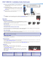
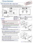
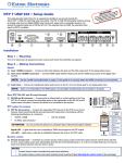
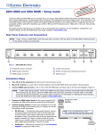
Product Category
FOX T USW 203 • Installation Guide
CLASS 1 LASER PRODUCT, see FOX T USW 203 User Guide at www.extron.com
This guide provides instructions for an experienced installer to install and connect the Extron FOX T USW 203 Universal Switcher with an
integrated fiber optic transmitter.
NOTE:
The FOX T USW 203 is not compatible with the FOX 3G HD-SDI, FOX 3G DVC, or FOX AV models.
WARNING: Risk of serious physical injury. The device outputs continuous invisible light, which may be harmful to the eyes; use
with caution.
Do not look into the fiber optic cable connectors or into the fiber optic cables themselves.
For additional safety, plug the attached dust caps into the optical transceivers when the fiber optic cable is unplugged.
Step 2 — Making Connections
RGB/R-Y, Y, B-Y
3
HDMI
AUDIO
LOOP-THRU
j ab
Tx
HDMI
Rx
LINK
POWER
12V
0.8 A MAX
Turn off or disconnect all equipment power sources and
mount the transmitter and receiver as required.
c
FOX T USW 203
2
Step 1 — Mounting
a
b
OUTPUTS
INPUTS
1
Installation
LINK
•
•
OPTICAL
c d e
f
REMOTE
RS-232
OVER FIBER ALARM
Tx Rx G
1
2
CONTACT
1
2
3
G
RS-232
Tx Rx G
g h i
Analog video input connector — Connect an analog RGB or YUV video source to this female 15-pin HD VGA connector, labeled input 1.
Analog video loop-thru connector — Connect an analog RGB or YUV video display to this female 15-pin HD VGA connector for a local
display. This output is always active.
HDMI input connectors — Connect a source device to these female HDMI connectors, labeled inputs 2 and 3. They can accept HDMI, DVI,
or DisplayPort video signals.
NOTE:
TIP:
Video input from a DisplayPort source must be a dual mode DisplayPort format.
Use an Extron LockIt® Lacing Bracket to secure an HDMI cable to each device as follows.
1.
2.
Plug the HDMI cable into the panel connector.
3.
Place a LockIt lacing bracket on the loosened screw and against the HDMI
connector, then tighten the screw to secure the bracket.
Loosen the HDMI connection mounting screw from the panel enough to allow a
LockIt lacing bracket to be placed over it. The screw does not have to be removed.
ATTENTION: Do not overtighten the HDMI connector mounting screw. The shield it
fastens to is very thin and can easily be stripped.
4.
5.
6.
Stacked
HDMI Connectors
If desired, repeat steps 2 and 3 for the opposite mounting screw and bracket.
Loosely place the included tie wrap around the HDMI connectors and the LockIt lacing brackets as shown.
While holding the connectors securely against the lacing bracket, use pliers or similar tools to tighten the tie wrap, then
remove any excess length.
d
Analog audio input connector — Connect an unbalanced analog audio input source to the 3.5 mm TRS jack. This is shared by all three
video inputs. HDMI embedded audio is given priority over analog audio.
e
HDMI switched output connector — Connect a display device to the female type A HDMI output connector for switched local HDMI output
of input 1, 2 or 3.
f
Fiber optic connector — Connect a fiber optic cable between the Tx port on the FOX T USW 203 and the Rx port on a receiver. To return
serial data from the receiver or for HDCP-compliance, connect a cable between the Tx port on the receiver and Rx port on the transmitter.
The Link LEDs for the Tx and Rx ports light when there is fiber light present on the corresponding port.
g
RS-232 Over Fiber and Alarm connector — To pass serial command signals to a receiver,
connect the host device to the leftmost poles (Tx, Rx, and G) of this 5-pole captive screw
connector. For remote monitoring of the status of fiber optic link 2, connect a custom
monitoring device to the rightmost poles (1 and 2) of this 5-pole captive screw connector.
Alarm Device
1
2
1
Tx Rx G
RS-232
OVER FIBER ALARM
2
Tx Rx G
RS-232 Device
1
FOX T USW 203 • Installation Guide (Continued)
h
i
j
Remote contact closure connector — Connect a suitable contact
closure device to this 3.5 mm, 4-pole captive screw connector for
remote input selection.
Remote RS-232 connector — For serial RS-232 control of the FOX
T USW 203 and firmware upgrades, connect a host device or control
system to this 3.5 mm, 3-pole captive screw connector (see Remote
Control below).
Power connector — Connect the provided 12 VDC external power
supply to this 2-pole captive screw connector.
CONTACT
1
2
Remote Contact Closure
Each port senses an external switch or contact closure.
Use these ports to select an input on the switcher.
3 G
Heat
Shrink
Over
Shield
Wires
Ground
Wire Nut
Device 3
G
3
2
1
k
Device 2
Switch
Device 1
Config port — Connect a host device, such as a computer, to the front panel mini Type B USB connector to provide
configuration, control, or firmware upgrades to the switcher (see Remote Control below).
(Switches,
relays, or
similar items)
AUTO
SWITCH
1
CONFIG
MODE
Operation
Input Selection Buttons
k
The three buttons with corresponding LEDs on the front panel (labeled Mode or 1, Normal or
2, and Auto or 3) manually select inputs 1 through 3 and enable different operating modes. The
LEDs light to indicate the active input and provide feedback.
Input selection
1
MODE
2
3
NORMAL
AUTO
Press the input selection button that corresponds with desired rear panel input connector to
activate that input signal.
Front panel lockout mode (executive mode)
Push and hold input buttons 1, 2, and 3 simultaneously for 5 seconds to enable or disable front panel configuration. All of the front panel LEDs
blink 3 times. In executive mode, contact closure and RS-232 control are still available.
Auto switch mode
Press and hold input buttons 1 and 3 simultaneously for 3 seconds. After releasing the buttons, the Auto Switch LED lights to indicate that auto
switch mode is enabled. This prioritizes the highest numbered active input.
NOTE:
Setting auto switch mode to prioritize the lowest numbered active input can be done only with SIS commands (see the
FOX T USW 203 User Guide for more details).
Normal switch mode
Press and hold inputs 1 and 2 simultaneously for 3 seconds. After releasing the buttons, the Auto Switch LED turns off to indicate that auto switch
mode is disabled. This is the default mode.
Remote Control
The FOX T USW 203 can be controlled through the Extron FOX Extenders Control Software, SIS commands, remote RS-232, or a contact closure
device (see Step 2 - Making Connections for connection details).
Install the FOX Extenders Control Software on a computer running a Windows® operating system. The control program can be installed from the
Extron Software Products DVD or downloaded from the Extron website, www.extron.com (see the
FOX T USW 203 User Guide).
Indicators
Auto Switch LED — Lights when the device is in auto switch mode.
Input selection LEDs — Light to signify status or give feedback of the currently selected input
(see Input Selection Buttons above).
Signal Status LEDs — Light when an input signal is detected on the corresponding input.
AUTO
SWITCH
1
STATUS
2
3
SIGNAL
HDCP
FOX T USW 203
HDCP status LEDs — Light when an HDMI input signal is HDCP compliant. Input 1 has no
HDCP capabilities.
2
FOX UNIVERSAL SWITCHER
Extron Headquarters
+1.800.633.9876 (Inside USA/Canada Only)
Extron Asia
+65.6383.4400
Extron China
+86.21.3760.1568)
Extron Korea
+82.2.3444.1571
Extron Europe
+31.33.453.4040
Extron Japan
+81.3.3511.7655
Extron Middle East
+971.4.299.1800
Extron India
+91.80.3055.3777
© 2013 Extron Electronics — All rights reserved. All trademarks mentioned are the property of their respective owners. www.extron.com
68-2226-50
Rev. A
07 13
NOR