1
Introduction
1
Network topologies
2
SIMATIC NET
Product properties
3
SCALANCE
Industrial Ethernet
SCALANCE X-100 and
SCALANCE X-200 Product Line
Installation and maintenance
4
Configuration / diagnostics
using remote mechanisms
5
IRT technology with
SCALANCE X-200
6
PROFINET IO functionality
7
Approvals and markings
8
References
9
Operating instructions
Dimension drawings
09/2006
A5E00349864 Release 7
10
Safety Guidelines
This manual contains notices you have to observe in order to ensure your personal safety, as well as to prevent
damage to property. The notices referring to your personal safety are highlighted in the manual by a safety alert
symbol, notices referring only to property damage have no safety alert symbol. These notices shown below are
graded according to the degree of danger.
Danger
indicates that death or severe personal injury will result if proper precautions are not taken.
Warning
indicates that death or severe personal injury may result if proper precautions are not taken.
Caution
with a safety alert symbol, indicates that minor personal injury can result if proper precautions are not taken.
Caution
without a safety alert symbol, indicates that property damage can result if proper precautions are not taken.
Notice
indicates that an unintended result or situation can occur if the corresponding information is not taken into
account.
If more than one degree of danger is present, the warning notice representing the highest degree of danger will
be used. A notice warning of injury to persons with a safety alert symbol may also include a warning relating to
property damage.
Qualified Personnel
The device/system may only be set up and used in conjunction with this documentation. Commissioning and
operation of a device/system may only be performed by qualified personnel. Within the context of the safety notes
in this documentation qualified persons are defined as persons who are authorized to commission, ground and
label devices, systems and circuits in accordance with established safety practices and standards.
Prescribed Usage
Note the following:
Warning
This device may only be used for the applications described in the catalog or the technical description and only in
connection with devices or components from other manufacturers which have been approved or recommended
by Siemens. Correct, reliable operation of the product requires proper transport, storage, positioning and
assembly as well as careful operation and maintenance.
Trademarks
All names identified by ® are registered trademarks of the Siemens AG. The remaining trademarks in this
publication may be trademarks whose use by third parties for their own purposes could violate the rights of the
owner.
Disclaimer of Liability
We have reviewed the contents of this publication to ensure consistency with the hardware and software
described. Since variance cannot be precluded entirely, we cannot guarantee full consistency. However, the
information in this publication is reviewed regularly and any necessary corrections are included in subsequent
editions.
Siemens AG
Automation and Drives
Postfach 48 48
90437 NÜRNBERG
GERMANY
Order No.: A5E00349864 Release 7
Edition 09/2006
Copyright © Siemens AG 2006.
Technical data subject to change
Table of contents
1
Introduction............................................................................................................................................. 1-1
1.1
2
3
Introduction ................................................................................................................................ 1-1
Network topologies ................................................................................................................................. 2-1
2.1
Network topologies .................................................................................................................... 2-1
2.2
Ring with redundancy manager ................................................................................................. 2-7
2.3
Redundant coupling of network segments................................................................................. 2-8
Product properties .................................................................................................................................. 3-1
3.1
Overview of the product characteristics..................................................................................... 3-1
3.2
Components of the product........................................................................................................ 3-4
3.3
Unpacking and checking............................................................................................................ 3-5
3.4
3.4.1
3.4.2
SCALANCE X108 ...................................................................................................................... 3-6
SCALANCE X108 product characteristics ................................................................................. 3-6
SCALANCE X108 TP ports........................................................................................................ 3-7
3.5
3.5.1
3.5.2
3.5.3
SCALANCE X104-2 ................................................................................................................... 3-9
SCALANCE X104-2 product characteristics.............................................................................. 3-9
SCALANCE X104-2 TP ports .................................................................................................. 3-10
SCALANCE X104-2 FO ports .................................................................................................. 3-12
3.6
3.6.1
3.6.2
3.6.3
SCALANCE X106-1 ................................................................................................................. 3-13
SCALANCE X106-1 product characteristics............................................................................ 3-13
SCALANCE X106-1 TP ports .................................................................................................. 3-14
SCALANCE X106-1 FO Port ................................................................................................... 3-16
3.7
3.7.1
3.7.2
SCALANCE X208 .................................................................................................................... 3-17
SCALANCE X208 product characteristics ............................................................................... 3-17
SCALANCE X208 TP ports...................................................................................................... 3-18
3.8
3.8.1
3.8.2
SCALANCE X208PRO ............................................................................................................ 3-20
SCALANCE X208PRO product characteristics ....................................................................... 3-20
SCALANCE X208PRO M12 Industrial Ethernet ports............................................................. 3-21
3.9
3.9.1
3.9.2
3.9.3
SCALANCE X204-2 ................................................................................................................. 3-23
SCALANCE X204-2 product characteristics............................................................................ 3-23
SCALANCE X204-2 TP ports .................................................................................................. 3-24
SCALANCE X204-2 FO ports .................................................................................................. 3-26
3.10
3.10.1
3.10.2
3.10.3
SCALANCE X206-1 ................................................................................................................. 3-27
SCALANCE X206-1 product characteristics............................................................................ 3-27
SCALANCE X206-1 TP ports .................................................................................................. 3-28
SCALANCE X206-1 FO ports .................................................................................................. 3-30
3.11
3.11.1
3.11.2
SCALANCE X204-2LD ............................................................................................................ 3-31
SCALANCE X204-2LD product characteristics ....................................................................... 3-31
SCALANCE X204-2LD TP ports.............................................................................................. 3-32
Industrial Ethernet SCALANCE X-100 and SCALANCE X-200 Product Line
Operating instructions, 09/2006, A5E00349864 Release 7
iii
Table of contents
4
iv
3.11.3
SCALANCE X204-2LD FO ports ............................................................................................. 3-34
3.12
3.12.1
3.12.2
3.12.3
SCALANCE X206-1LD............................................................................................................. 3-36
SCALANCE X206-1LD product characteristics ....................................................................... 3-36
SCALANCE X206-1LD TP ports.............................................................................................. 3-37
SCALANCE X206-1LD FO ports ............................................................................................. 3-39
3.13
3.13.1
3.13.2
3.13.3
SCALANCE X202-2IRT ........................................................................................................... 3-41
SCALANCE X202-2IRT product characteristics ...................................................................... 3-41
SCALANCE X202-2IRT TP ports............................................................................................. 3-42
SCALANCE X202-2IRT FO ports ............................................................................................ 3-44
3.14
3.14.1
3.14.2
SCALANCE X204IRT............................................................................................................... 3-45
SCALANCE X204IRT product characteristics ......................................................................... 3-45
SCALANCE X204IRT TP ports................................................................................................ 3-46
3.15
3.15.1
3.15.2
3.15.3
SCALANCE X202-2P IRT ........................................................................................................ 3-48
SCALANCE X202-2P IRT product characteristics................................................................... 3-48
SCALANCE X202-2P IRT TP ports ......................................................................................... 3-49
SCALANCE X202-2P IRT FO ports......................................................................................... 3-51
3.16
3.16.1
3.16.2
3.16.3
SCALANCE X201-3P IRT ........................................................................................................ 3-52
SCALANCE X201-3P IRT product characteristics................................................................... 3-52
SCALANCE X201-3P IRT TP ports ......................................................................................... 3-53
SCALANCE X201-3P IRT FO ports......................................................................................... 3-55
3.17
3.17.1
3.17.2
SCALANCE X200-4P IRT ........................................................................................................ 3-56
SCALANCE X200-4P IRT product characteristics................................................................... 3-56
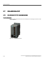
SCALANCE X200-4P IRT FO ports......................................................................................... 3-57
3.18
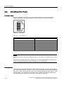
C-PLUG (configuration plug) for SCALANCE X-200 ............................................................... 3-58
3.19
3.19.1
3.19.2
Button ....................................................................................................................................... 3-60
SCALANCE X-100 button ........................................................................................................ 3-60
SCALANCE X-200 button ........................................................................................................ 3-60
3.20
3.20.1
3.20.2
3.20.3
3.20.4
3.20.5
3.20.6
3.20.7
Displays.................................................................................................................................... 3-62
Fault indicator (red LED) .......................................................................................................... 3-62
Power display........................................................................................................................... 3-63
Port status indicator (green/yellow LEDs)................................................................................ 3-64
Redundancy manager indicator (green LED) .......................................................................... 3-65
Standby functions (yellow LED) ............................................................................................... 3-66
FOC diagnostic display (yellow LED)....................................................................................... 3-67
LED display during startup ....................................................................................................... 3-68
3.21
Technical specifications ........................................................................................................... 3-69
Installation and maintenance .................................................................................................................. 4-1
4.1
4.1.1
4.1.2
4.1.3
Installation .................................................................................................................................. 4-1
Installation on a DIN rail ............................................................................................................. 4-2
Installation on a standard rail ..................................................................................................... 4-3
Wall mounting ............................................................................................................................ 4-4
4.2
4.2.1
4.2.2
4.2.3
4.2.4
Connecting ................................................................................................................................. 4-5
Power supply.............................................................................................................................. 4-5
Signaling contact........................................................................................................................ 4-6
Grounding................................................................................................................................... 4-7
Fitting the IE FC RJ-45 Plug 180 ............................................................................................... 4-7
4.3
Maintenance............................................................................................................................... 4-9
Industrial Ethernet SCALANCE X-100 and SCALANCE X-200 Product Line
Operating instructions, 09/2006, A5E00349864 Release 7
Table of contents
5
6
Configuration / diagnostics using remote mechanisms ........................................................................... 5-1
5.1
5.1.1
5.1.2
5.1.2.1
5.1.2.2
5.1.2.3
5.1.2.4
5.1.2.5
5.1.2.6
5.1.3
Assignment of an IP address ..................................................................................................... 5-1
Introduction ................................................................................................................................ 5-1
Configuration with the Primary Setup Tool ................................................................................ 5-2
Configuration with the Primary Setup Tool ................................................................................ 5-2
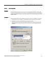
Installing the Primary Setup Tool ............................................................................................... 5-2
The DLC protocol....................................................................................................................... 5-3
Installing the DLC protocol......................................................................................................... 5-4
Working with the Primary Setup Tool ........................................................................................ 5-4
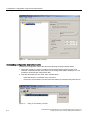
Configuring a module................................................................................................................. 5-5
Configuration with DHCP ........................................................................................................... 5-8
5.2
5.2.1
5.2.2
5.2.3
5.2.4
5.2.5
5.2.6
5.2.6.1
5.2.6.2
5.2.6.3
5.2.6.4
5.2.6.5
5.2.6.6
5.2.6.7
5.2.6.8
5.2.6.9
5.2.6.10
5.2.6.11
5.2.6.12
5.2.6.13
5.2.6.14
5.2.6.15
5.2.6.16
5.2.6.17
5.2.6.18
5.2.6.19
5.2.6.20
5.2.6.21
5.2.6.22
5.2.6.23
5.2.6.24
5.2.6.25
5.2.6.26
5.2.6.27
5.2.6.28
5.2.6.29
5.2.6.30
5.2.7
5.2.7.1
5.2.7.2
5.2.8
5.2.8.1
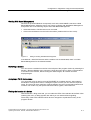
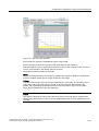
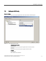
Configuration with Web Based Management (WBM) ................................................................ 5-8
Principle ..................................................................................................................................... 5-8
Requirements for Web Based Management.............................................................................. 5-8
Starting WBM ........................................................................................................................... 5-10
LED simulation ......................................................................................................................... 5-11
Working with WBM................................................................................................................... 5-11
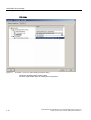
WBM menus............................................................................................................................. 5-13
Management menus - the Start menu ..................................................................................... 5-13
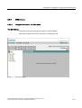
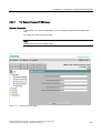
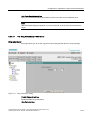
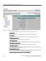
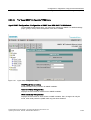
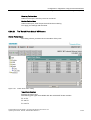
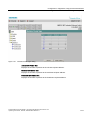
The "System Configuration" WBM menu................................................................................. 5-14
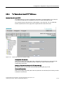
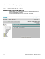
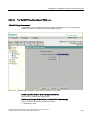
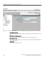
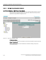
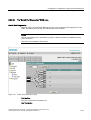
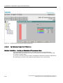
The "System Restart & Defaults" WBM menu ......................................................................... 5-15
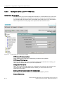
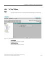
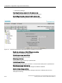
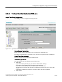
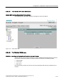
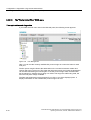
The "System Save & Load HTTP" WBM menu ....................................................................... 5-17
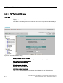
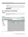
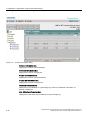
The "System Save & Load TFTP" WBM menu........................................................................ 5-18
The "System Version Numbers" WBM menu .......................................................................... 5-19
The "System Passwords" WBM menu..................................................................................... 5-21
The "System Event Log Table" WBM menu ............................................................................ 5-22
The "Status" WBM menu ......................................................................................................... 5-23
The "Fault Mask" WBM menu.................................................................................................. 5-24
The "Ring Redundancy" WBM menu....................................................................................... 5-25
The "X200IRT Ring Redundancy" WBM menu ....................................................................... 5-27
The "X200IRT Standby Manager" WBM menu........................................................................ 5-30
The "C-PLUG Information" WBM menu................................................................................... 5-32
The "Agent Configuration" WBM menu.................................................................................... 5-34
The "Agent Event Configuration" WBM menu ......................................................................... 5-35
The "Agent E-Mail Configuration" WBM menu ........................................................................ 5-37
The "Agent SNMP Configuration" WBM menu ........................................................................ 5-39
The "Agent Trap Configuration" WBM menu ........................................................................... 5-40
The "Agent Time Client Configuration" WBM menu ................................................................ 5-41
The "Switch Configuration (Port Mirroring)" WBM menu ......................................................... 5-42
The "Switch Ports Status" WBM menu .................................................................................... 5-43
The "Switch Port Diagnostics" WBM menu ............................................................................. 5-45
The "Switch Forwarding Database" WBM menu ..................................................................... 5-46
The "Switch ARP Table" WBM menu ...................................................................................... 5-47
The "Statistics" WBM menu ..................................................................................................... 5-47
The "Statistics Packet Size" WBM menu................................................................................. 5-49
The "Statistics Packet Type" WBM menu ................................................................................ 5-50
The "Statistics Packet Error" WBM menu ................................................................................ 5-52
The "Plastic Optical Fiber" WBM menu ................................................................................... 5-54
SNMP....................................................................................................................................... 5-56
Configuration and diagnostics over SNMP .............................................................................. 5-56
MIB variables ........................................................................................................................... 5-57
Configuration over Command Line Interface (CLI) .................................................................. 5-60
Command Line Interface (CLI)................................................................................................. 5-60
IRT technology with SCALANCE X-200.................................................................................................. 6-1
Industrial Ethernet SCALANCE X-100 and SCALANCE X-200 Product Line
Operating instructions, 09/2006, A5E00349864 Release 7
v
Table of contents
7
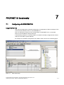
PROFINET IO functionality ..................................................................................................................... 7-1
7.1
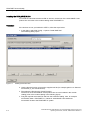
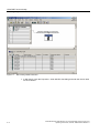
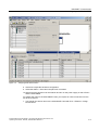
Configuring with PROFINET IO ................................................................................................. 7-1
7.2
Settings in HW Config ................................................................................................................ 7-7
7.3
Access options with PNIO........................................................................................................ 7-11
8
Approvals and markings ......................................................................................................................... 8-1
9
References ............................................................................................................................................. 9-1
9.1
10
References ................................................................................................................................. 9-1
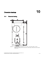
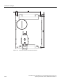
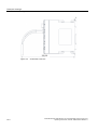
Dimension drawings ............................................................................................................................. 10-1
10.1
Dimension drawing................................................................................................................... 10-1
Glossary .....................................................................................................................................Glossary-1
Index................................................................................................................................................ Index-1
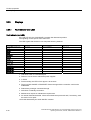
Tables
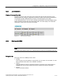
Table 3-1
Overview of the product characteristics ..................................................................................... 3-1
Table 3-2
Overview of the product characteristics ..................................................................................... 3-2
Table 3-3
Overview of the connection options ........................................................................................... 3-3
Table 3-4
Overview of the connection options for IRT devices.................................................................. 3-3
Table 3-5
Overview of the components supplied ....................................................................................... 3-4
Table 3-6
Overview of the components supplied ....................................................................................... 3-4
Table 3-7
Pin assignment........................................................................................................................... 3-7
Table 3-8
Pin assignment......................................................................................................................... 3-10
Table 3-9
Pin assignment......................................................................................................................... 3-14
Table 3-10
Pin assignment......................................................................................................................... 3-18
Table 3-11
Pin assignment......................................................................................................................... 3-21
Table 3-12
Pin assignment......................................................................................................................... 3-24
Table 3-13
Pin assignment......................................................................................................................... 3-28
Table 3-14
Pin assignment......................................................................................................................... 3-32
Table 3-15
Pin assignment......................................................................................................................... 3-37
Table 3-16
Pin assignment......................................................................................................................... 3-42
Table 3-17
Pin assignment......................................................................................................................... 3-46
Table 3-18
Pin assignment......................................................................................................................... 3-49
Table 3-19
Pin assignment......................................................................................................................... 3-53
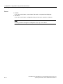
Table 3-20
Ports ......................................................................................................................................... 3-69
Table 3-21
Electrical data........................................................................................................................... 3-70
Table 3-22
Signaling contact...................................................................................................................... 3-71
Table 3-23
Permitted cable lengths (copper) ............................................................................................. 3-71
vi
Industrial Ethernet SCALANCE X-100 and SCALANCE X-200 Product Line
Operating instructions, 09/2006, A5E00349864 Release 7
Table of contents
Table 3-24
Permitted cable lengths (fiber-optic) ........................................................................................ 3-72
Table 3-25
Aging time/ MTBF .................................................................................................................... 3-72
Table 3-26
Permitted ambient conditions................................................................................................... 3-73
Table 3-27
Order numbers ......................................................................................................................... 3-74
Table 4-1
Pin assignment........................................................................................................................... 4-5
Table 4-2
Pin assignment........................................................................................................................... 4-6
Table 5-1
Variables in the System directory ............................................................................................ 5-57
Table 5-2
Variables in the Interface directory .......................................................................................... 5-58
Industrial Ethernet SCALANCE X-100 and SCALANCE X-200 Product Line
Operating instructions, 09/2006, A5E00349864 Release 7
vii
Introduction
1.1
1
Introduction
The devices of the SCALANCE X-100 are unmanaged Industrial Ethernet switches with up
to eight ports and on-site diagnostics for applications in the vicinity of the machinery.
The devices of the SCALANCE X-200 are managed Industrial Ethernet switches that can be
used universally for applications ranging from those in the vicinity of the machinery to
networked units. Configuration engineering and remote diagnostics are integrated in the
SIMATIC STEP 7 engineering tool increasing the plant availability. Devices with a high
degree of protection allow installation without a cabinet.
With the SCALANCE X-200 IRT switches (IRT = isochronous real time), SIMATIC NET
offers the first Industrial Ethernet real-time switches from the new SCALANCE series with
innovative housing concept and integrated ERTEC (Enhanced Real-Time Controller). By
using the "cut through" switching mechanism, the switches are ideal to meet the real-time
requirements of PROFINET.
What is possible?
The devices of the SCALANCE X-100 or SCALANCE X-200 product lines, allow the costeffective installation of Industrial Ethernet bus, star, or ring structures with switching
functionality.
By using the “cut through” switching mechanism, the SCALANCE X-200IRT switches are
ideal to meet the real-time requirements of PROFINET.
Cut through is not possible
• between a port set to 10 Mbps and a port set to 100 Mbps
• when two packets are to be sent at the same time on one port.
One particular advantage of the SCALANCE X-200IRT switches in PROFINET networks is
the integrated ERTEC. This gives priority to PROFINET packets when forwarding.
Note
It is not possible to use devices of the SCALANCE X-100 product line in a redundant ring
because they do not support redundancy.
Industrial Ethernet SCALANCE X-100 and SCALANCE X-200 Product Line
Operating instructions, 09/2006, A5E00349864 Release 7
1-1
Introduction
1.1 Introduction
Note
The requirements of EN61000-4-5, surge test on power supply lines are met only when a
Blitzductor VT AD 24V type no. 918 402 is used
Manufacturer:
DEHN+SÖHNE GmbH+Co.KG Hans Dehn Str.1 Postfach 1640 D-92306 Neumarkt,
Germany
Warning
When used under hazardous conditions (zone 2), the devices of the SCALANCE X-100 and
SCALANCE X-200 product lines must be installed in an enclosure.
To comply with ATEX100a (EN 60079-15), this enclosure must meet the requirements of at
least IP54 in compliance with EN 60529.
WARNING – EXPLOSION HAZARD: DO NOT DISCONNECT EQUIPMENT WHEN A
FLAMMABLE OR COMBUSTIBLE ATMOSPHERE IS PRESENT.
Note
The specified approvals apply only when the corresponding mark is printed on the product.
Purpose of the Operating Instructions
These operating instructions support you when commissioning networks with the devices of
the product line SCALANCE X-100 and X-200.
1-2
Industrial Ethernet SCALANCE X-100 and SCALANCE X-200 Product Line
Operating instructions, 09/2006, A5E00349864 Release 7
Introduction
1.1 Introduction
Validity of the Operating Instructions
These operating instructions are valid for the following devices:
SIMATIC NET SCALANCE X108 6GK5108-0BA00-2AA3
SIMATIC NET SCALANCE X104-2 6GK5104-2BB00-2AA3
SIMATIC NET SCALANCE X106-1 6GK5106-1BB00-2AA3
SIMATIC NET SCALANCE X208 6GK5208-0BA00-2AA3
SIMATIC NET SCALANCE X208PRO 6GK5208-0HA00-2AA6
SIMATIC NET SCALANCE X204-2 6GK5204-2BB00-2AA3
SIMATIC NET SCALANCE X206-1 6GK5206-1BB00-2AA3
SIMATIC NET SCALANCE X204-2LD 6GK5204-2BC00-2AA3
SIMATIC NET SCALANCE X206-1LD 6GK5206-1BC00-2AA3
SIMATIC NET SCALANCE X202-2IRT 6GK5202-2BB00-2BA3
SIMATIC NET SCALANCE X204IRT 6GK5204-0BA00-2BA3
SIMATIC NET SCALANCE X202-2P IRT 6GK5202-2BH00-2BA3
SIMATIC NET SCALANCE X201-3P IRT 6GK5201-3BH00-2BA3
SIMATIC NET SCALANCE X200-4P IRT 6GK5200-4AH00-2BA3
Further documentation
The "SIMATIC NET Industrial Ethernet Twisted Pair and Fiber Optic Networks“ manual
contains additional information on other SIMATIC NET products that you can operate along
with the devices of the SCALANCE X-100 and X-200 product lines in an Industrial Ethernet
network.
Finding information
To help you to find the information you require more quickly, the manual includes not only
the table of contents but also the following sections in the Appendix:
• Index
• Glossary
Audience
These operating instructions are intended for persons involved in commissioning networks
with the devices of the SCALANCE X-100 and X-200 product lines.
Standards and approvals
The devices of the SCALANCE X-100 and X-200 product lines meet the requirements for the
CE mark. You will find detailed information in the section "Approvals and markings" in these
operating instructions.
Industrial Ethernet SCALANCE X-100 and SCALANCE X-200 Product Line
Operating instructions, 09/2006, A5E00349864 Release 7
1-3
Network topologies
2.1
2
Network topologies
Switching technology allows extensive networks to be set up with numerous nodes and
simplifies network expansion.
Which topologies can be implemented?
Bus, ring, or star topologies can be implemented with the devices of the SCALANCE X-100
or SCALANCE X-200 product lines.
Note
Make sure that the maximum permitted cable lengths for the relevant devices are not
exceeded. You will find the permitted cable lengths in the technical specifications.
For example, with X202-2P IRT, X201-3P IRT and X200P IRT only 50 m POF or 100 m HCS
cable may be used.
Industrial Ethernet SCALANCE X-100 and SCALANCE X-200 Product Line
Operating instructions, 09/2006, A5E00349864 Release 7
2-1
Network topologies
2.1 Network topologies
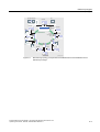
Bus topology
Figure 2-1
Electrical / optical linear topology with SCALANCE X-100
Figure 2-2
Electrical star topology, example with SCALANCE X108
Star topology
2-2
Industrial Ethernet SCALANCE X-100 and SCALANCE X-200 Product Line
Operating instructions, 09/2006, A5E00349864 Release 7
Network topologies
2.1 Network topologies
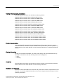
Figure 2-3
Optical star topology, example with SCALANCE X-400 and SCALANCE X206-1
Industrial Ethernet SCALANCE X-100 and SCALANCE X-200 Product Line
Operating instructions, 09/2006, A5E00349864 Release 7
2-3
Network topologies
2.1 Network topologies
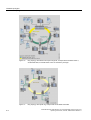
Ring topology
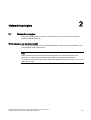
Figure 2-4
2-4
Optical ring topology, example with SCALANCE X-200 and SCALANCE X-400 as
redundancy manager
Industrial Ethernet SCALANCE X-100 and SCALANCE X-200 Product Line
Operating instructions, 09/2006, A5E00349864 Release 7
Network topologies
2.1 Network topologies
PC
Operator Station
S7-400
S7-400
Switch
SCALANCE
X-400
PC
S7-300
Twisted Pair
S7-400
Switch
SCALANCE
X208
S7-300
PC
PC
S7-400
S7-300
S7-400
PC
S7-400
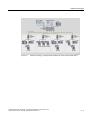
Figure 2-5
G_IK10_XX_10101
Electrical ring topology, example with SCALANCE X208 and SCALANCE X-400 as
redundancy manager
Industrial Ethernet SCALANCE X-100 and SCALANCE X-200 Product Line
Operating instructions, 09/2006, A5E00349864 Release 7
2-5
Network topologies
2.1 Network topologies
2-6
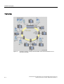
Figure 2-6
Ring topology with electrical and optical ring links, example with SCALANCE X206-1,
SCALANCE X208, and SCALANCE X-400 as redundancy manager
Figure 2-7
Ring topology with optical ring, example with SCALANCE X202-2IRT
Industrial Ethernet SCALANCE X-100 and SCALANCE X-200 Product Line
Operating instructions, 09/2006, A5E00349864 Release 7
Network topologies
2.2 Ring with redundancy manager
To increase availability, optical or electrical bus topologies made up of SCALANCE X-200
switches with a SCALANCE X-200IRT, SCALANCE X414-3E, OSM Version 2, or ESM
Version 2 configured as a redundancy manager can be closed to form a ring. The
SCALANCE X-200 switches are first connected over their ring ports to form a bus. The two
ends of the bus are closed to form a ring by a switch operating in the redundancy manager
mode. Devices of the SCALANCE X-200 IRT, SCALANCE X400 product families, or OSMs /
ESMs can be used as redundancy managers. When a switch is used as the redundancy
manager, the ring ports are isolated from each other if the network is operating problem-free.
The SCALANCE X-200IRT, SCALANCE X414-3E, or OSM / ESM operating in the
redundancy manager mode monitors the connected bus over its ring ports and switches the
ring ports through if there is an interruption on the connected bus; in other words, it restores
a functioning bus over this substitute path. Reconfiguration takes place within 0.3 seconds.
As soon as the problem has been eliminated, the original topology is restored; in other
words, the ring ports in the redundancy manager are once again disconnected from each
other.
2.2
Ring with redundancy manager
To increase network availability, optical, electrical, or mixed bus topologies comprising up to
50 switches (SCALANCE X-400, SCALANCE X-200 or OSM/ESM) can be closed to form a
ring.
Functional description
The two ends of the bus are closed to form a ring by a SCALANCE X-200IRT operating as a
redundancy manager. The redundancy function is enabled and disabled by pressing a button
on the front of the device or with the WEB interface (cannot be set by PNIO).
In contrast to the ring ports of the other switches, the ring ports of the redundancy manager
are disconnected when the network is operating problem-free. The SCALANCE X-200IRT
operating in the redundancy manager mode monitors the connected bus over its ring ports
and switches the ring ports through if there is an interruption on the connected bus; in other
words, it restores a functioning bus over this substitute path. Reconfiguration takes place
within 0.3 seconds. As soon as the problem has been eliminated, the original topology is
restored; in other words, the ring ports in the redundancy manager are once again
disconnected from each other.
In a SCALANCE X204IRT, ports 1 and 2 are set as ring ports. In a SCALANCE X202-2IRT,
ports 3 and 4 (optical ports) are set as ring ports. This setting can also be changed with the
WEB interface.
After the RM function has been enabled or after the RM has been switched through, this is
indicated by the RM LED on the housing.
Only one switch can be configured as a redundancy manager in a ring.
Industrial Ethernet SCALANCE X-100 and SCALANCE X-200 Product Line
Operating instructions, 09/2006, A5E00349864 Release 7
2-7
Network topologies
2.3 Redundant coupling of network segments
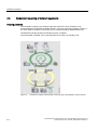
2.3
Redundant coupling of network segments
Coupling possibility
The redundant coupling of two network segments shown here as an example is only
possible between SCALANCE X-200IRT devices, since this requires the standby function of
the SCALANCE X-200IRT. This function can be configured with the WEB interface only.
The RM LED indicates whether the standby function is enabled.
The SCALANCE X-200IRT can be operated either as an RM or in standby mode.
Figure 2-8
2-8
Redundant coupling of SCALANCE X-200 rings with 2 SCALANCE X-200 IRT devices
Industrial Ethernet SCALANCE X-100 and SCALANCE X-200 Product Line
Operating instructions, 09/2006, A5E00349864 Release 7
3
Product properties
3.1
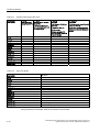
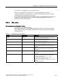
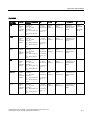
Overview of the product characteristics
Table 3-1
Overview of the product characteristics
Device type SCALANCE
X108
X104-2
X106-1
X208
X208PRO
X204-2
X206-1
X204-2
LD
X206-1
LD
SIMATIC environment
+
+
+
+
+
+
+
+
+
Diagnostics LED
+
+
+
+
+
+
+
+
+
24 V DC
+
+
+
+
+
+
+
+
+
Compact housing
(securing collar, etc.)
+
+
+
+
+
+
+
+
+
2x 24 V DC
+
+
+
+
+
+
+
+
+
Signaling contact + onsite operation
+
+
+
+
+
+
+
+
+
Diagnostics: Web,
SNMP, PROFINET
-
-
-
+
+
+
+
+
+
C-PLUG
-
-
-
+
+
+
+
+
+
IRT capability
-
-
-
-
-
-
-
-
-
Fast learning
-
-
-
+
+
+
+
+
+
Passive listening
-
-
-
+
+
+
+
+
+
Log table
-
-
-
-
-
-
-
-
-
SNTP + SICLOCK
-
-
-
-
-
-
-
-
-
Cut through
-
-
-
-
-
-
-
-
-
Use in ring possible
(not as RM)
-
-
-
+
+
+
+
+
+
Redundancy manager
-
-
-
-
-
-
-
-
-
Standby manager
-
-
-
-
-
-
-
-
-
Fast learning:
Fast recognition of MAC addresses on the device that change during operation (for example,
when an end node is reconnected).
Industrial Ethernet SCALANCE X-100 and SCALANCE X-200 Product Line
Operating instructions, 09/2006, A5E00349864 Release 7
3-1
Product properties
3.1 Overview of the product characteristics
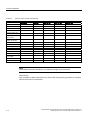
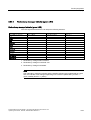
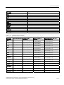
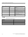
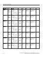
Table 3-2
Overview of the product characteristics
Device type SCALANCE
X202-2IRT
X204IRT
SIMATIC environment
+
+
X202-2P IRT
+
X201-3P IRT
+
X200-4P IRT
+
Diagnostics LED
+
+
+
+
+
24 V DC
+
+
+
+
+
Compact housing
(securing collar, etc.)
+
+
+
+
+
2x 24 V DC
+
+
+
+
+
Signaling contact + onsite operation
+
+
+
+
+
Diagnostics: Web,
SNMP, PROFINET
+
+
+
+
+
C-PLUG
+
+
+
+
+
IRT capability
+
+
+
+
+
Fast learning
+
+
+
+
+
Passive listening
+
+
+
+
+
Log table
+
+
+
+
+
SNTP + SICLOCK
+
+
+
+
+
Cut through
+
+
+
+
+
Use in ring possible
(not as RM)
+
+
+
+
+
Redundancy manager
+
+
+
+
+
Standby manager
+
+
+
+
+
Note
IRT switches cannot be redundancy and standby manager at the same time.
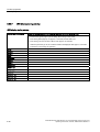
Fast learning:
Fast recognition of MAC addresses on the device that change during operation (for example,
when an end node is reconnected).
3-2
Industrial Ethernet SCALANCE X-100 and SCALANCE X-200 Product Line
Operating instructions, 09/2006, A5E00349864 Release 7
Product properties
3.1 Overview of the product characteristics
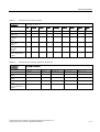
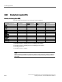
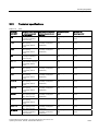
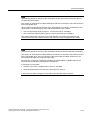
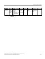
Table 3-3
Overview of the connection options
Fast Ethernet
Device type SCALANCE
10/100 Mbps
X108
X104-2
X106-1
X208
X208PRO
X204-2
X206-1
X204-2
LD
X206-1
LD
TP (RJ-45)
8
4
6
8
-
4
6
4
6
M12
208PRO only
-
-
-
-
8
-
-
-
-
Fiber
multimode
(BFOC)
-
2
1
-
-
2
1
-
-
Fiber
single mode
(BFOC)
-
-
-
-
-
-
-
2
1
Fiber
POF / PCF
(SC-RJ)
-
-
-
-
-
-
-
-
-
The following ports are
set as ring ports when
supplied
-
-
-
P1, P2
P1, P2
P5, P6
P1, P2
P5, P6
P1, P2
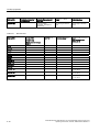
Table 3-4
Overview of the connection options for IRT devices
Fast Ethernet
Device type SCALANCE
10/100 Mbps
X202-2IRT
X204IRT
X202-2P IRT
X201-3P IRT
X200-4P IRT
TP (RJ-45)
2
4
2
1
-
Fiber multimode
(BFOC)
2
-
-
-
-
Fiber single mode
(BFOC)
-
-
-
-
-
Fiber POF / PCF
(SC-RJ)
-
-
2
3
4
P3, P4
P1, P2
P3, P4
P3, P4
P3, P4
The following ports are
set as ring ports when
supplied
Industrial Ethernet SCALANCE X-100 and SCALANCE X-200 Product Line
Operating instructions, 09/2006, A5E00349864 Release 7
3-3
Product properties
3.2 Components of the product
3.2
Components of the product
Table 3-5
Overview of the components supplied
Device type
SCALANCE
Device
2-pin plug-in
terminal block
4-pin plug-in
terminal block
Product
information
CD
Operating
instructions
PST
tool
GSD
file
SNMP OPC
profile
X108
+
+
+
+
+
+
+
+
X104-2
+
+
+
+
+
+
+
+
X106-1
+
+
+
+
+
+
+
+
X208
+
+
+
+
+
+
+
+
X204-2
+
+
+
+
+
+
+
+
X206-1
+
+
+
+
+
+
+
+
X204-2 LD
+
+
+
+
+
+
+
+
X206-1 LD
+
+
+
+
+
+
+
+
X202-2IRT
+
+
+
+
+
+
+
+
X204IRT
+
+
+
+
+
+
+
+
X202-2PIRT
+
+
+
+
+
+
+
+
X201-3PIRT
+
+
+
+
+
+
+
+
X200-4PIRT
+
+
+
+
+
+
+
+
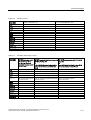
The PST tool, the GSD file and the SNMP OPC profile can only be used for devices of the
SCALANCE X-200 product line.
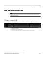
Table 3-6
Device type
SCALANCE
X208PRO
3-4
Overview of the components supplied
Device
+
Protective
Protective
covers for M12
covers for M12
Ethernet sockets Ethernet
connector
interfaces
8
3
Product
information
+
CD
Operating
instructions
PST
tool
GSD
file
SNMP OPC
profile
+
+
+
+
Industrial Ethernet SCALANCE X-100 and SCALANCE X-200 Product Line
Operating instructions, 09/2006, A5E00349864 Release 7
Product properties
3.3 Unpacking and checking
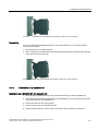
3.3
Unpacking and checking
Unpacking, checking
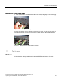
1. Make sure that the package is complete.
2. Check all the parts for transport damage.
Warning
Do not use any parts that show evidence of damage!
Industrial Ethernet SCALANCE X-100 and SCALANCE X-200 Product Line
Operating instructions, 09/2006, A5E00349864 Release 7
3-5
Product properties
3.4 SCALANCE X108
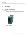
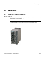
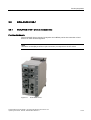
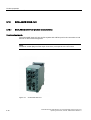
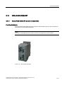
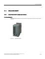
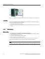
3.4
SCALANCE X108
3.4.1
SCALANCE X108 product characteristics
Possible attachments
The SCALANCE X108 has eight RJ-45 jacks for the connection of end devices or other
network segments.
Figure 3-1
3-6
SCALANCE X108
Industrial Ethernet SCALANCE X-100 and SCALANCE X-200 Product Line
Operating instructions, 09/2006, A5E00349864 Release 7
Product properties
3.4 SCALANCE X108
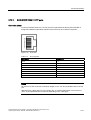
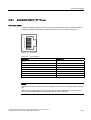
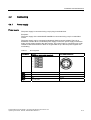
3.4.2
SCALANCE X108 TP ports
Connector pinout
On the SCALANCE X108, the twisted-pair ports are implemented as RJ-45 jacks with MDI-X
assignment (Medium Dependent Interface–Autocrossover) of a network component.
Figure 3-2
RJ-45 jack
Table 3-7
Pin assignment
Pin number
Assignment
Pin 8
n. c.
Pin 7
n. c.
Pin 6
TD-
Pin 5
n. c.
Pin 4
n. c.
Pin 3
TD+
Pin 2
RD-
Pin 1
RD+
Notice
TP cords or TP-XP cords with a maximum length of 10 m can be connected to the RJ-45 TP
port.
With the IE FC cables and IE FC RJ-45 plug 180, an overall cable length of up to 100 m is
permitted between two devices depending on the cable type.
Autonegotiation
Autonegotiation means the automatic detection of the functionality of the port at the opposite
end. Using autonegotiation, repeaters or end devices can detect the functionality available at
the port of a partner device allowing automatic configuration of different types of device. With
Industrial Ethernet SCALANCE X-100 and SCALANCE X-200 Product Line
Operating instructions, 09/2006, A5E00349864 Release 7
3-7
Product properties
3.4 SCALANCE X108
autonegotiation, two components connected to a link segment can exchange parameters
and set themselves to match the supported communication functionality.
Note
Devices not supporting autonegotiation must be set to 100 Mbps/ half duplex or 10 Mbps
half duplex.
Note
The SCALANCE X108 is a plug-and-play device that does not require settings to be made
for commissioning.
MDI /MDIX autocrossover function
The advantage of the MDI /MDIX autocrossover function is that straight-through cables can
be used throughout and crossover Ethernet cables are unnecessary. This prevents
malfunctions resulting from mismatching send and receive wires. This makes installation
much easier for the user.
The devices of the SCALANCE X-100 and X-200 product lines all support the MDI / MDIX
autocrossover function.
Notice
Please note that the direct connection of two ports on the switch or accidental connection
over several switches causes an illegal loop. Such a loop can lead to network overload and
network failures.
Auto polarity exchange
If the pair of receiving cables are incorrectly connected (RD+ and RD- swapped over), the
polarity is reversed automatically.
3-8
Industrial Ethernet SCALANCE X-100 and SCALANCE X-200 Product Line
Operating instructions, 09/2006, A5E00349864 Release 7
Product properties
3.5 SCALANCE X104-2
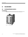
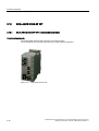
3.5
SCALANCE X104-2
3.5.1
SCALANCE X104-2 product characteristics
Possible attachments
The SCALANCE X104-2 has four RJ-45 jacks and two BFOC ports for the connection of end
devices or other network segments.
Note
The BFOC socket (Bayonet Fiber Optic Connector) corresponds to the ST socket.
Figure 3-3
SCALANCE X104-2
Industrial Ethernet SCALANCE X-100 and SCALANCE X-200 Product Line
Operating instructions, 09/2006, A5E00349864 Release 7
3-9
Product properties
3.5 SCALANCE X104-2
3.5.2
SCALANCE X104-2 TP ports
Connector pinout
On the SCALANCE X104-2, the TP ports are implemented as RJ-45 jacks with MDI-X
assignment (Medium Dependent Interface–Autocrossover) of a network component.
Figure 3-4
RJ-45 jack
Table 3-8
Pin assignment
Pin number
Assignment
Pin 8
n. c.
Pin 7
n. c.
Pin 6
TD-
Pin 5
n. c.
Pin 4
n. c.
Pin 3
TD+
Pin 2
RD-
Pin 1
RD+
Notice
TP cords or TP-XP cords with a maximum length of 10 m can be connected to the RJ-45 TP
port.
With the IE FC cables and IE FC RJ-45 plug 180, an overall cable length of a maximum of
100 m is permitted between two devices depending on the cable type.
Autonegotiation
Autonegotiation means the automatic detection of the functionality of the port at the opposite
end. Using autonegotiation, repeaters or end devices can detect the functionality available at
the port of a partner device allowing automatic configuration of different types of device. With
autonegotiation, two components connected to a link segment can exchange parameters
and set themselves to match the supported communication functionality.
3-10
Industrial Ethernet SCALANCE X-100 and SCALANCE X-200 Product Line
Operating instructions, 09/2006, A5E00349864 Release 7
Product properties
3.5 SCALANCE X104-2
Note
Devices not supporting autonegotiation must be set to 100 Mbps/ half duplex or 10 Mbps
half duplex.
Note
The SCALANCE X104-2 is a plug-and-play device that does not require settings to be made
for commissioning.
MDI /MDIX autocrossover function
The advantage of the MDI /MDIX autocrossover function is that straight-through cables can
be used throughout and crossover Ethernet cables are unnecessary. This prevents
malfunctions resulting from mismatching send and receive wires. This makes installation
much easier for the user.
The devices of the SCALANCE X-100 and X-200 product lines all support the MDI / MDIX
autocrossover function.
Notice
Please note that the direct connection of two ports on the switch or accidental connection
over several switches causes an illegal loop. Such a loop can lead to network overload and
network failures.
Auto polarity exchange
If the pair of receiving cables are incorrectly connected (RD+ and RD- swapped over), the
polarity is reversed automatically.
Industrial Ethernet SCALANCE X-100 and SCALANCE X-200 Product Line
Operating instructions, 09/2006, A5E00349864 Release 7
3-11
Product properties
3.5 SCALANCE X104-2
3.5.3
SCALANCE X104-2 FO ports
Transmission rate
The transmission rate of the optical Fast Ethernet ports is 100 Mbps.
Transmission mode
The transmission mode for 100Base-FX is specified in the IEEE 802.3 standard.
Since the full duplex mode and the transmission rate cannot be modified for optical
transmission, autonegotiation cannot be selected.
Transmission medium
Data transmission is over multimode fiber-optic cable (FOC). The wavelength is 1310 nm.
Multimode fiber-optic cables are used with a core of 50 or 62.5 µm; the light source is an
LED.
The outer diameter of the FOC is 125 µm.
Transmission range
The maximum transmission range (segment length) is 3 km.
Connectors
The cables are connected over BFOC sockets.
3-12
Industrial Ethernet SCALANCE X-100 and SCALANCE X-200 Product Line
Operating instructions, 09/2006, A5E00349864 Release 7
Product properties
3.6 SCALANCE X106-1
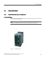
3.6
SCALANCE X106-1
3.6.1
SCALANCE X106-1 product characteristics
Possible attachments
The SCALANCE X106-1 has six RJ-45 jacks and a BFOC port for the connection of end
devices or other network segments.
Note
The BFOC socket (Bayonet Fiber Optic Connector) corresponds to the ST socket.
Figure 3-5
SCALANCE X106-1
Industrial Ethernet SCALANCE X-100 and SCALANCE X-200 Product Line
Operating instructions, 09/2006, A5E00349864 Release 7
3-13
Product properties
3.6 SCALANCE X106-1
3.6.2
SCALANCE X106-1 TP ports
Connector pinout
On the SCALANCE X106-1, the TP ports are implemented as RJ-45 jacks with MDI-X
assignment (Medium Dependent Interface–Autocrossover) of a network component.
Figure 3-6
RJ-45 jack
Table 3-9
Pin assignment
Pin number
Assignment
Pin 8
n. c.
Pin 7
n. c.
Pin 6
TD-
Pin 5
n. c.
Pin 4
n. c.
Pin 3
TD+
Pin 2
RD-
Pin 1
RD+
Notice
TP cords or TP-XP cords with a maximum length of 10 m can be connected to the RJ-45 TP
port.
With the IE FC cables and IE FC RJ-45 plug 180, an overall cable length of a maximum of
100 m is permitted between two devices depending on the cable type.
3-14
Industrial Ethernet SCALANCE X-100 and SCALANCE X-200 Product Line
Operating instructions, 09/2006, A5E00349864 Release 7
Product properties
3.6 SCALANCE X106-1
Autonegotiation
Autonegotiation means the automatic detection of the functionality of the port at the opposite
end. Using autonegotiation, repeaters or end devices can detect the functionality available at
the port of a partner device allowing automatic configuration of different types of device. With
autonegotiation, two components connected to a link segment can exchange parameters
and set themselves to match the supported communication functionality.
Note
Devices not supporting autonegotiation must be set to 100 Mbps/ half duplex or 10 Mbps
half duplex.
Note
The SCALANCE X106-1 is a plug-and-play device that does not require settings to be made
for commissioning.
MDI /MDIX autocrossover function
The advantage of the MDI /MDIX autocrossover function is that straight-through cables can
be used throughout and crossover Ethernet cables are unnecessary. This prevents
malfunctions resulting from mismatching send and receive wires. This makes installation
much easier for the user.
The devices of the SCALANCE X-100 and X-200 product lines all support the MDI / MDIX
autocrossover function.
Notice
Please note that the direct connection of two ports on the switch or accidental connection
over several switches causes an illegal loop. Such a loop can lead to network overload and
network failures.
Auto polarity exchange
If the pair of receiving cables are incorrectly connected (RD+ and RD- swapped over), the
polarity is reversed automatically.
Industrial Ethernet SCALANCE X-100 and SCALANCE X-200 Product Line
Operating instructions, 09/2006, A5E00349864 Release 7
3-15
Product properties
3.6 SCALANCE X106-1
3.6.3
SCALANCE X106-1 FO Port
Transmission rate
The transmission rate of the optical Fast Ethernet ports is 100 Mbps.
Transmission mode
The transmission mode for 100Base-FX is specified in the IEEE 802.3 standard.
Since the full duplex mode and the transmission rate cannot be modified for optical
transmission, autonegotiation cannot be selected.
Transmission medium
Data transmission is over multimode fiber-optic cable (FOC). The wavelength is 1310 nm.
Multimode fiber-optic cables are used with a core of 50 or 62.5 µm; the light source is an
LED.
The outer diameter of the FOC is 125 µm.
Transmission range
The maximum transmission range (segment length) is 3 km.
Connectors
The cables are connected over BFOC sockets.
3-16
Industrial Ethernet SCALANCE X-100 and SCALANCE X-200 Product Line
Operating instructions, 09/2006, A5E00349864 Release 7
Product properties
3.7 SCALANCE X208
3.7
SCALANCE X208
3.7.1
SCALANCE X208 product characteristics
Possible attachments
The SCALANCE X208 has eight RJ-45 jacks for the connection of end devices or other
network segments.
Figure 3-7
SCALANCE X208
Industrial Ethernet SCALANCE X-100 and SCALANCE X-200 Product Line
Operating instructions, 09/2006, A5E00349864 Release 7
3-17
Product properties
3.7 SCALANCE X208
3.7.2
SCALANCE X208 TP ports
Connector pinout
On the SCALANCE X208, the TP ports are implemented as RJ--45 jacks with MDI-X
assignment (Medium Dependent Interface–Autocrossover) of a network component.
Figure 3-8
RJ-45 jack
Table 3-10
Pin assignment
Pin number
Assignment
Pin 8
n. c.
Pin 7
n. c.
Pin 6
TD-
Pin 5
n. c.
Pin 4
n. c.
Pin 3
TD+
Pin 2
RD-
Pin 1
RD+
Notice
TP cords or TP-XP cords with a maximum length of 10 m can be connected to the RJ-45 TP
port.
With the IE FC cables and IE FC RJ-45 plug 180, an overall cable length of up to 100 m is
permitted between two devices depending on the cable type.
3-18
Industrial Ethernet SCALANCE X-100 and SCALANCE X-200 Product Line
Operating instructions, 09/2006, A5E00349864 Release 7
Product properties
3.7 SCALANCE X208
Autonegotiation
Autonegotiation means the automatic detection of the functionality of the port at the opposite
end. Using autonegotiation, repeaters or end devices can detect the functionality available at
the port of a partner device allowing automatic configuration of different types of device. With
autonegotiation, two components connected to a link segment can exchange parameters
and set themselves to match the supported communication functionality.
Note
Devices not supporting autonegotiation must be set to 100 Mbps/ half duplex or 10 Mbps
half duplex.
Note
The SCALANCE X208 is a plug-and-play device that does not require settings to be made
for commissioning.
MDI /MDIX autocrossover function
The advantage of the MDI /MDIX autocrossover function is that straight-through cables can
be used throughout and crossover Ethernet cables are unnecessary. This prevents
malfunctions resulting from mismatching send and receive wires. This makes installation
much easier for the user.
The devices of the SCALANCE X-100 and X-200 product lines all support the MDI / MDIX
autocrossover function.
Notice
Please note that the direct connection of two ports on the switch or accidental connection
over several switches causes an illegal loop. Such a loop can lead to network overload and
network failures.
Auto polarity exchange
If the pair of receiving cables are incorrectly connected (RD+ and RD- swapped over), the
polarity is reversed automatically.
Industrial Ethernet SCALANCE X-100 and SCALANCE X-200 Product Line
Operating instructions, 09/2006, A5E00349864 Release 7
3-19
Product properties
3.8 SCALANCE X208PRO
3.8
SCALANCE X208PRO
3.8.1
SCALANCE X208PRO product characteristics
Possible attachments
The SCALANCE X208PRO has eight Industrial Ethernet M12 sockets with the high degree
of protection IP65 for the connection of end devices or other network segments.
Figure 3-9
3-20
SCALANCE X208PRO
Industrial Ethernet SCALANCE X-100 and SCALANCE X-200 Product Line
Operating instructions, 09/2006, A5E00349864 Release 7
Product properties
3.8 SCALANCE X208PRO
3.8.2
SCALANCE X208PRO M12 Industrial Ethernet ports
Connector pinout
On the SCALANCE X208PRO, the Industrial Ethernet ports are implemented according to
the PROFINET standard as 4-pin M12 sockets, d-coded with the MDI-X assignment
(Medium Dependent Interface-Autocrossover) of a network component.
Figure 3-10
SCALANCE 208PRO Ethernet socket M12
Table 3-11
Pin assignment
Pin number
Assignment as a network component
Pin 1
RX+
Pin 2
TX+
Pin 3
RX-
Pin 4
TX-
Notice
With IE FC cable and IE M12 Plug PRO, an overall cable length of up to 100 m is permitted
between two devices depending on the cable type.
Autonegotiation
Autonegotiation means the automatic detection of the functionality of the port at the opposite
end. Using autonegotiation, repeaters or end devices can detect the functionality available at
the port of a partner device allowing automatic configuration of different types of device. With
autonegotiation, two components connected to a link segment can exchange parameters
and set themselves to match the supported communication functionality.
Industrial Ethernet SCALANCE X-100 and SCALANCE X-200 Product Line
Operating instructions, 09/2006, A5E00349864 Release 7
3-21
Product properties
3.8 SCALANCE X208PRO
Note
Devices not supporting autonegotiation must be set to 100 Mbps/ half duplex or 10 Mbps
half duplex.
Note
The SCALANCE X208PRO is a plug-and-play device that does not require settings to be
made for commissioning.
MDI /MDIX autocrossover function
The advantage of the MDI /MDIX autocrossover function is that straight-through cables can
be used throughout and crossover Ethernet cables are unnecessary. This prevents
malfunctions resulting from mismatching send and receive wires. This makes installation
much easier for the user.
The devices of the SCALANCE X-100 and X-200 product lines all support the MDI / MDIX
autocrossover function.
Notice
Please note that the direct connection of two ports on the switch or accidental connection
over several switches causes an illegal loop. Such a loop can lead to network overload and
network failures.
Auto polarity exchange
If the pair of receiving cables are incorrectly connected (RD+ and RD- swapped over), the
polarity is reversed automatically.
3-22
Industrial Ethernet SCALANCE X-100 and SCALANCE X-200 Product Line
Operating instructions, 09/2006, A5E00349864 Release 7
Product properties
3.9 SCALANCE X204-2
3.9
SCALANCE X204-2
3.9.1
SCALANCE X204-2 product characteristics
Possible attachments
The SCALANCE X204-2 has four RJ-45 jacks and two BFOC ports for the connection of end
devices or other network segments.
Note
The BFOC socket (Bayonet Fiber Optic Connector) corresponds to the ST socket.
Figure 3-11
SCALANCE X204-2
Industrial Ethernet SCALANCE X-100 and SCALANCE X-200 Product Line
Operating instructions, 09/2006, A5E00349864 Release 7
3-23
Product properties
3.9 SCALANCE X204-2
3.9.2
SCALANCE X204-2 TP ports
Connector pinout
On the SCALANCE X204-2, the TP ports are implemented as RJ-45 jacks with MDI-X
assignment (Medium Dependent Interface–Autocrossover) of a network component.
Figure 3-12
RJ-45 jack
Table 3-12
Pin assignment
Pin number
Assignment
Pin 8
n. c.
Pin 7
n. c.
Pin 6
TD-
Pin 5
n. c.
Pin 4
n. c.
Pin 3
TD+
Pin 2
RD-
Pin 1
RD+
Notice
TP cords or TP-XP cords with a maximum length of 10 m can be connected to the RJ-45 TP
port.
With the IE FC cables and IE FC RJ-45 plug 180, an overall cable length of a maximum of
100 m is permitted between two devices depending on the cable type.
3-24
Industrial Ethernet SCALANCE X-100 and SCALANCE X-200 Product Line
Operating instructions, 09/2006, A5E00349864 Release 7
Product properties
3.9 SCALANCE X204-2
Autonegotiation
Autonegotiation means the automatic detection of the functionality of the port at the opposite
end. Using autonegotiation, repeaters or end devices can detect the functionality available at
the port of a partner device allowing automatic configuration of different types of device. With
autonegotiation, two components connected to a link segment can exchange parameters
and set themselves to match the supported communication functionality.
Note
Devices not supporting autonegotiation must be set to 100 Mbps/ half duplex or 10 Mbps
half duplex.
Note
The SCALANCE X204-2 is a plug-and-play device that does not require settings to be made
for commissioning.
MDI /MDIX autocrossover function
The advantage of the MDI /MDIX autocrossover function is that straight-through cables can
be used throughout and crossover Ethernet cables are unnecessary. This prevents
malfunctions resulting from mismatching send and receive wires. This makes installation
much easier for the user.
The devices of the SCALANCE X-100 and X-200 product lines all support the MDI / MDIX
autocrossover function.
Notice
Please note that the direct connection of two ports on the switch or accidental connection
over several switches causes an illegal loop. Such a loop can lead to network overload and
network failures.
Auto polarity exchange
If the pair of receiving cables are incorrectly connected (RD+ and RD- swapped over), the
polarity is reversed automatically.
Industrial Ethernet SCALANCE X-100 and SCALANCE X-200 Product Line
Operating instructions, 09/2006, A5E00349864 Release 7
3-25
Product properties
3.9 SCALANCE X204-2
3.9.3
SCALANCE X204-2 FO ports
Transmission rate
The transmission rate of the optical Fast Ethernet ports is 100 Mbps.
Transmission mode
The transmission mode for 100Base-FX is specified in the IEEE 802.3 standard.
Since the full duplex mode and the transmission rate cannot be modified for optical
transmission, autonegotiation cannot be selected.
Transmission medium
Data transmission is over multimode fiber-optic cable (FOC). The wavelength is 1310 nm.
Multimode fiber-optic cables are used with a core of 50 or 62.5 µm; the light source is an
LED.
The outer diameter of the FOC is 125 µm.
Transmission range
The maximum transmission range (segment length) is 3 km.
Connectors
The cables are connected over BFOC sockets.
3-26
Industrial Ethernet SCALANCE X-100 and SCALANCE X-200 Product Line
Operating instructions, 09/2006, A5E00349864 Release 7
Product properties
3.10 SCALANCE X206-1
3.10
SCALANCE X206-1
3.10.1
SCALANCE X206-1 product characteristics
Possible attachments
The SCALANCE X206-1 has six RJ-45 jacks and a BFOC port for the connection of end
devices or other network segments.
Note
The BFOC socket (Bayonet Fiber Optic Connector) corresponds to the ST socket.
Figure 3-13
SCALANCE X206-1
Industrial Ethernet SCALANCE X-100 and SCALANCE X-200 Product Line
Operating instructions, 09/2006, A5E00349864 Release 7
3-27
Product properties
3.10 SCALANCE X206-1
3.10.2
SCALANCE X206-1 TP ports
Connector pinout
On the SCALANCE X206-1, the TP ports are implemented as RJ-45 jacks with MDI-X
assignment (Medium Dependent Interface–Autocrossover) of a network component.
Figure 3-14
RJ-45 jack
Table 3-13
Pin assignment
Pin number
Assignment
Pin 8
n. c.
Pin 7
n. c.
Pin 6
TD-
Pin 5
n. c.
Pin 4
n. c.
Pin 3
TD+
Pin 2
RD-
Pin 1
RD+
Notice
TP cords or TP-XP cords with a maximum length of 10 m can be connected to the RJ-45 TP
port.
With the IE FC cables and IE FC RJ-45 plug 180, an overall cable length of a maximum of
100 m is permitted between two devices depending on the cable type.
3-28
Industrial Ethernet SCALANCE X-100 and SCALANCE X-200 Product Line
Operating instructions, 09/2006, A5E00349864 Release 7
Product properties
3.10 SCALANCE X206-1
Autonegotiation
Autonegotiation means the automatic detection of the functionality of the port at the opposite
end. Using autonegotiation, repeaters or end devices can detect the functionality available at
the port of a partner device allowing automatic configuration of different types of device. With
autonegotiation, two components connected to a link segment can exchange parameters
and set themselves to match the supported communication functionality.
Note
Devices not supporting autonegotiation must be set to 100 Mbps/ half duplex or 10 Mbps
half duplex.
Note
The SCALANCE X206-1 is a plug-and-play device that does not require settings to be made
for commissioning.
MDI /MDIX autocrossover function
The advantage of the MDI /MDIX autocrossover function is that straight-through cables can
be used throughout and crossover Ethernet cables are unnecessary. This prevents
malfunctions resulting from mismatching send and receive wires. This makes installation
much easier for the user.
The devices of the SCALANCE X-100 and X-200 product lines all support the MDI / MDIX
autocrossover function.
Notice
Please note that the direct connection of two ports on the switch or accidental connection
over several switches causes an illegal loop. Such a loop can lead to network overload and
network failures.
Auto polarity exchange
If the pair of receiving cables are incorrectly connected (RD+ and RD- swapped over), the
polarity is reversed automatically.
Industrial Ethernet SCALANCE X-100 and SCALANCE X-200 Product Line
Operating instructions, 09/2006, A5E00349864 Release 7
3-29
Product properties
3.10 SCALANCE X206-1
3.10.3
SCALANCE X206-1 FO ports
Transmission rate
The transmission rate of the optical Fast Ethernet ports is 100 Mbps.
Transmission mode
The transmission mode for 100Base-FX is specified in the IEEE 802.3 standard.
Since the full duplex mode and the transmission rate cannot be modified for optical
transmission, autonegotiation cannot be selected.
Transmission medium
Data transmission is over multimode fiber-optic cable (FOC). The wavelength is 1310 nm.
Multimode fiber-optic cables are used with a core of 50 or 62.5 µm; the light source is an
LED.
The outer diameter of the FOC is 125 µm.
Transmission range
The maximum transmission range (segment length) is 3 km.
Connectors
The cables are connected over BFOC sockets.
3-30
Industrial Ethernet SCALANCE X-100 and SCALANCE X-200 Product Line
Operating instructions, 09/2006, A5E00349864 Release 7
Product properties
3.11 SCALANCE X204-2LD
3.11
SCALANCE X204-2LD
3.11.1
SCALANCE X204-2LD product characteristics
Possible attachments
The SCALANCE X204-2LD has four RJ-45 jacks and two BFOC ports for the connection of
end devices or other network segments.
Note
The BFOC socket (Bayonet Fiber Optic Connector) corresponds to the ST socket.
Figure 3-15
SCALANCE X204-2LD
Industrial Ethernet SCALANCE X-100 and SCALANCE X-200 Product Line
Operating instructions, 09/2006, A5E00349864 Release 7
3-31
Product properties
3.11 SCALANCE X204-2LD
3.11.2
SCALANCE X204-2LD TP ports
Connector pinout
On the SCALANCE X204-2LD, the TP ports are implemented as RJ-45 jacks with MDI-X
assignment (Medium Dependent Interface–Autocrossover) of a network component.
Figure 3-16
RJ-45 jack
Table 3-14
Pin assignment
Pin number
Assignment
Pin 8
n. c.
Pin 7
n. c.
Pin 6
TD-
Pin 5
n. c.
Pin 4
n. c.
Pin 3
TD+
Pin 2
RD-
Pin 1
RD+
Notice
TP cords or TP-XP cords with a maximum length of 10 m can be connected to the RJ-45 TP
port.
With the IE FC cables and IE FC RJ-45 plug 180, an overall cable length of a maximum of
100 m is permitted between two devices depending on the cable type.
3-32
Industrial Ethernet SCALANCE X-100 and SCALANCE X-200 Product Line
Operating instructions, 09/2006, A5E00349864 Release 7
Product properties
3.11 SCALANCE X204-2LD
Autonegotiation
Autonegotiation means the automatic detection of the functionality of the port at the opposite
end. Using autonegotiation, repeaters or end devices can detect the functionality available at
the port of a partner device allowing automatic configuration of different types of device. With
autonegotiation, two components connected to a link segment can exchange parameters
and set themselves to match the supported communication functionality.
Note
Devices not supporting autonegotiation must be set to 100 Mbps/ half duplex or 10 Mbps
half duplex.
Note
The SCALANCE X204-2LD is a plug-and-play device that does not require settings to be
made for commissioning.
MDI /MDIX autocrossover function
The advantage of the MDI /MDIX autocrossover function is that straight-through cables can
be used throughout and crossover Ethernet cables are unnecessary. This prevents
malfunctions resulting from mismatching send and receive wires. This makes installation
much easier for the user.
The devices of the SCALANCE X-100 and X-200 product lines all support the MDI / MDIX
autocrossover function.
Notice
Please note that the direct connection of two ports on the switch or accidental connection
over several switches causes an illegal loop. Such a loop can lead to network overload and
network failures.
Auto polarity exchange
If the pair of receiving cables are incorrectly connected (RD+ and RD- swapped over), the
polarity is reversed automatically.
Industrial Ethernet SCALANCE X-100 and SCALANCE X-200 Product Line
Operating instructions, 09/2006, A5E00349864 Release 7
3-33
Product properties
3.11 SCALANCE X204-2LD
3.11.3
SCALANCE X204-2LD FO ports
Transmission rate
The transmission rate of the optical Fast Ethernet ports is 100 Mbps.
Transmission mode
The transmission mode for 100Base-FX is specified in the IEEE 802.3 standard.
Since the full duplex mode and the transmission rate cannot be modified for optical
transmission, autonegotiation cannot be selected.
Transmission medium
Data transmission is over single mode fiber-optic cable (FOC). The wavelength is 1310 nm.
Single mode fiber-optic cables are used with a core of 10 µm; the light source is an LED.
The outer diameter of the FOC is 125 µm.
Transmission range
The maximum transmission range (segment length) is 26 km.
Connectors
The cables are connected over BFOC sockets.
3-34
Industrial Ethernet SCALANCE X-100 and SCALANCE X-200 Product Line
Operating instructions, 09/2006, A5E00349864 Release 7
Product properties
3.11 SCALANCE X204-2LD
Note
The SCALANCE X204-2LD may only be coupled over its optical ports with
• SCALANCE X204-2LD
• SCALANCE X206-1LD
• SCALANCE X-400 with module type MM491-2LD
• SCALANCE X101-LD
• OMC TP11-LD
• OSM ITP62-LD
Coupling optical ports with
• SCALANCE X106-1
• SCALANCE X104-2
• SCALANCE X206-1
• SCALANCE X204-2
• SCALANCE X202-2IRT
• SCALANCE X-400 with module type MM491-2
• OMC TP11
• OSM ITP62
• OSM ITP53
• OSM TP62
is not permitted.
Industrial Ethernet SCALANCE X-100 and SCALANCE X-200 Product Line
Operating instructions, 09/2006, A5E00349864 Release 7
3-35
Product properties
3.12 SCALANCE X206-1LD
3.12
SCALANCE X206-1LD
3.12.1
SCALANCE X206-1LD product characteristics
Possible attachments
The SCALANCE X206-1LD has six RJ-45 jacks and a BFOC port for the connection of end
devices or other network segments.
Note
The BFOC socket (Bayonet Fiber Optic Connector) corresponds to the ST socket.
Figure 3-17
3-36
SCALANCE X206-1LD
Industrial Ethernet SCALANCE X-100 and SCALANCE X-200 Product Line
Operating instructions, 09/2006, A5E00349864 Release 7
Product properties
3.12 SCALANCE X206-1LD
3.12.2
SCALANCE X206-1LD TP ports
Connector pinout
On the SCALANCE X206-1LD, the TP ports are implemented as RJ-45 jacks with MDI-X
assignment (Medium Dependent Interface–Autocrossover) of a network component.
Figure 3-18
RJ-45 jack
Table 3-15
Pin assignment
Pin number
Assignment
Pin 8
n. c.
Pin 7
n. c.
Pin 6
TD-
Pin 5
n. c.
Pin 4
n. c.
Pin 3
TD+
Pin 2
RD-
Pin 1
RD+
Notice
TP cords or TP-XP cords with a maximum length of 10 m can be connected to the RJ-45 TP
port.
With the IE FC cables and IE FC RJ-45 plug 180, an overall cable length of a maximum of
100 m is permitted between two devices depending on the cable type.
Industrial Ethernet SCALANCE X-100 and SCALANCE X-200 Product Line
Operating instructions, 09/2006, A5E00349864 Release 7
3-37
Product properties
3.12 SCALANCE X206-1LD
Autonegotiation
Autonegotiation means the automatic detection of the functionality of the port at the opposite
end. Using autonegotiation, repeaters or end devices can detect the functionality available at
the port of a partner device allowing automatic configuration of different types of device. With
autonegotiation, two components connected to a link segment can exchange parameters
and set themselves to match the supported communication functionality.
Note
Devices not supporting autonegotiation must be set to 100 Mbps/ half duplex or 10 Mbps
half duplex.
Note
The SCALANCE X206-1LD is a plug-and-play device that does not require settings to be
made for commissioning.
MDI /MDIX autocrossover function
The advantage of the MDI /MDIX autocrossover function is that straight-through cables can
be used throughout and crossover Ethernet cables are unnecessary. This prevents
malfunctions resulting from mismatching send and receive wires. This makes installation
much easier for the user.
The devices of the SCALANCE X-100 and X-200 product lines all support the MDI / MDIX
autocrossover function.
Notice
Please note that the direct connection of two ports on the switch or accidental connection
over several switches causes an illegal loop. Such a loop can lead to network overload and
network failures.
Auto polarity exchange
If the pair of receiving cables are incorrectly connected (RD+ and RD- swapped over), the
polarity is reversed automatically.
3-38
Industrial Ethernet SCALANCE X-100 and SCALANCE X-200 Product Line
Operating instructions, 09/2006, A5E00349864 Release 7
Product properties
3.12 SCALANCE X206-1LD
3.12.3
SCALANCE X206-1LD FO ports
Transmission rate
The transmission rate of the optical Fast Ethernet ports is 100 Mbps.
Transmission mode
The transmission mode for 100Base-FX is specified in the IEEE 802.3 standard.
Since the full duplex mode and the transmission rate cannot be modified for optical
transmission, autonegotiation cannot be selected.
Transmission medium
Data transmission is over single mode fiber-optic cable (FOC). The wavelength is 1310 nm.
Single mode fiber-optic cables are used with a core of 10 µm; the light source is an LED.
The outer diameter of the FOC is 125 µm.
Transmission range
The maximum transmission range (segment length) is 26 km.
Connectors
The cables are connected over BFOC sockets.
Industrial Ethernet SCALANCE X-100 and SCALANCE X-200 Product Line
Operating instructions, 09/2006, A5E00349864 Release 7
3-39
Product properties
3.12 SCALANCE X206-1LD
Note
The SCALANCE X206-1LD may only be coupled over its optical ports with
• SCALANCE X204-2LD
• SCALANCE X206-1LD
• SCALANCE X-400 with module type MM491-2LD
• SCALANCE X101-LD
• OMC TP11-LD
• OSM ITP62-LD
Coupling optical ports with
• SCALANCE X106-1
• SCALANCE X104-2
• SCALANCE X206-1
• SCALANCE X204-2
• SCALANCE X202-2IRT
• SCALANCE X-400 with module type MM491-2
• OMC TP11
• OSM ITP62
• OSM ITP53
• OSM TP62
is not permitted.
3-40
Industrial Ethernet SCALANCE X-100 and SCALANCE X-200 Product Line
Operating instructions, 09/2006, A5E00349864 Release 7
Product properties
3.13 SCALANCE X202-2IRT
3.13
SCALANCE X202-2IRT
3.13.1
SCALANCE X202-2IRT product characteristics
Possible attachments
The SCALANCE X202-2IRT has two RJ-45 jacks and two BFOC ports for the connection of
end devices or other network segments.
Note
The BFOC socket (Bayonet Fiber Optic Connector) corresponds to the ST socket.
Figure 3-19
SCALANCE X202-2IRT
Industrial Ethernet SCALANCE X-100 and SCALANCE X-200 Product Line
Operating instructions, 09/2006, A5E00349864 Release 7
3-41
Product properties
3.13 SCALANCE X202-2IRT
3.13.2
SCALANCE X202-2IRT TP ports
Connector pinout
On the SCALANCE X202-2IRT, the TP ports are implemented as RJ-45 jacks with MDI-X
assignment (Medium Dependent Interface–Autocrossover) of a network component.
Figure 3-20
RJ-45 jack
Table 3-16
Pin assignment
Pin number
Assignment
Pin 8
n. c.
Pin 7
n. c.
Pin 6
TD-
Pin 5
n. c.
Pin 4
n. c.
Pin 3
TD+
Pin 2
RD-
Pin 1
RD+
Notice
TP cords or TP-XP cords with a maximum length of 10 m can be connected to the RJ-45 TP
port.
With the IE FC cables and IE FC RJ-45 plug 180, an overall cable length of a maximum of
100 m is permitted between two devices depending on the cable type.
3-42
Industrial Ethernet SCALANCE X-100 and SCALANCE X-200 Product Line
Operating instructions, 09/2006, A5E00349864 Release 7
Product properties
3.13 SCALANCE X202-2IRT
Autonegotiation
Autonegotiation means the automatic detection of the functionality of the port at the opposite
end. Using autonegotiation, repeaters or end devices can detect the functionality available at
the port of a partner device allowing automatic configuration of different types of device. With
autonegotiation, two components connected to a link segment can exchange parameters
and set themselves to match the supported communication functionality.
Note
Devices not supporting autonegotiation must be set to 100 Mbps/ half duplex or 10 Mbps
half duplex.
Note
The SCALANCE X202-2IRT is a plug-and-play device that does not require settings to be
made for commissioning.
MDI /MDIX autocrossover function
The advantage of the MDI /MDIX autocrossover function is that straight-through cables can
be used throughout and crossover Ethernet cables are unnecessary. This prevents
malfunctions resulting from mismatching send and receive wires. This makes installation
much easier for the user.
The devices of the SCALANCE X-100 and X-200 product lines all support the MDI / MDIX
autocrossover function.
Notice
Please note that the direct connection of two ports on the switch or accidental connection
over several switches causes an illegal loop. Such a loop can lead to network overload and
network failures.
Auto polarity exchange
If the pair of receiving cables are incorrectly connected (RD+ and RD- swapped over), the
polarity is reversed automatically.
Industrial Ethernet SCALANCE X-100 and SCALANCE X-200 Product Line
Operating instructions, 09/2006, A5E00349864 Release 7
3-43
Product properties
3.13 SCALANCE X202-2IRT
3.13.3
SCALANCE X202-2IRT FO ports
Transmission rate
The transmission rate of the optical Fast Ethernet ports is 100 Mbps.
Transmission mode
The transmission mode for 100Base-FX is specified in the IEEE 802.3 standard.
Since the full duplex mode and the transmission rate cannot be modified for optical
transmission, autonegotiation cannot be selected.
Transmission medium
Data transmission is over multimode fiber-optic cable (FOC). The wavelength is 1310 nm.
Multimode fiber-optic cables are used with a core of 50 or 62.5 µm; the light source is an
LED.
The outer diameter of the FOC is 125 µm.
Transmission range
The maximum transmission range (segment length) is 3 km.
Connectors
The cables are connected over BFOC sockets.
3-44
Industrial Ethernet SCALANCE X-100 and SCALANCE X-200 Product Line
Operating instructions, 09/2006, A5E00349864 Release 7
Product properties
3.14 SCALANCE X204IRT
3.14
SCALANCE X204IRT
3.14.1
SCALANCE X204IRT product characteristics
Possible attachments
The SCALANCE X204IRT has four RJ-45 jacks for connecting end devices or other network
segments.
Figure 3-21
SCALANCE X204IRT
Industrial Ethernet SCALANCE X-100 and SCALANCE X-200 Product Line
Operating instructions, 09/2006, A5E00349864 Release 7
3-45
Product properties
3.14 SCALANCE X204IRT
3.14.2
SCALANCE X204IRT TP ports
Connector pinout
On the SCALANCE X204IRT, the TP ports are implemented as RJ-45 jacks with MDI-X
assignment (Medium Dependent Interface–Autocrossover) of a network component.
Figure 3-22
RJ-45 jack
Table 3-17
Pin assignment
Pin number
Assignment
Pin 8
n. c.
Pin 7
n. c.
Pin 6
TD-
Pin 5
n. c.
Pin 4
n. c.
Pin 3
TD+
Pin 2
RD-
Pin 1
RD+
Notice
TP cords or TP-XP cords with a maximum length of 10 m can be connected to the RJ-45 TP
port.
With the IE FC cables and IE FC RJ-45 plug 180, an overall cable length of up to 100 m is
permitted between two devices depending on the cable type.
3-46
Industrial Ethernet SCALANCE X-100 and SCALANCE X-200 Product Line
Operating instructions, 09/2006, A5E00349864 Release 7
Product properties
3.14 SCALANCE X204IRT
Autonegotiation
Autonegotiation means the automatic detection of the functionality of the port at the opposite
end. Using autonegotiation, repeaters or end devices can detect the functionality available at
the port of a partner device allowing automatic configuration of different types of device. With
autonegotiation, two components connected to a link segment can exchange parameters
and set themselves to match the supported communication functionality.
Note
Devices not supporting autonegotiation must be set to 100 Mbps/ half duplex or 10 Mbps
half duplex.
Note
The SCALANCE X204IRT is a plug-and-play device that does not require settings to be
made for commissioning.
MDI /MDIX autocrossover function
The advantage of the MDI /MDIX autocrossover function is that straight-through cables can
be used throughout and crossover Ethernet cables are unnecessary. This prevents
malfunctions resulting from mismatching send and receive wires. This makes installation
much easier for the user.
The devices of the SCALANCE X-100 and X-200 product lines all support the MDI / MDIX
autocrossover function.
Notice
Please note that the direct connection of two ports on the switch or accidental connection
over several switches causes an illegal loop. Such a loop can lead to network overload and
network failures.
Auto polarity exchange
If the pair of receiving cables are incorrectly connected (RD+ and RD- swapped over), the
polarity is reversed automatically.
Industrial Ethernet SCALANCE X-100 and SCALANCE X-200 Product Line
Operating instructions, 09/2006, A5E00349864 Release 7
3-47
Product properties
3.15 SCALANCE X202-2P IRT
3.15
SCALANCE X202-2P IRT
3.15.1
SCALANCE X202-2P IRT product characteristics
Possible attachments
The SCALANCE X202-2P IRT has two RJ-45 jacks and two
SC RJ interfaces for connecting end devices or other network segments.
Figure 3-23
3-48
SCALANCE X202-2P IRT
Industrial Ethernet SCALANCE X-100 and SCALANCE X-200 Product Line
Operating instructions, 09/2006, A5E00349864 Release 7
Product properties
3.15 SCALANCE X202-2P IRT
3.15.2
SCALANCE X202-2P IRT TP ports
Connector pinout
On the SCALANCE X202-2P IRT, the TP ports are implemented as RJ-45 jacks with MDI-X
assignment (Medium Dependent Interface–Autocrossover) of a network component.
Figure 3-24
RJ-45 jack
Table 3-18
Pin assignment
Pin number
Assignment
Pin 8
n. c.
Pin 7
n. c.
Pin 6
TD-
Pin 5
n. c.
Pin 4
n. c.
Pin 3
TD+
Pin 2
RD-
Pin 1
RD+
Notice
TP cords or TP-XP cords with a maximum length of 10 m can be connected to the RJ-45 TP
port.
With the IE FC cables and IE FC RJ-45 plug 180, an overall cable length of a maximum of
100 m is permitted between two devices depending on the cable type.
Industrial Ethernet SCALANCE X-100 and SCALANCE X-200 Product Line
Operating instructions, 09/2006, A5E00349864 Release 7
3-49
Product properties
3.15 SCALANCE X202-2P IRT
Autonegotiation
Autonegotiation means the automatic detection of the functionality of the port at the opposite
end. Using autonegotiation, repeaters or end devices can detect the functionality available at
the port of a partner device allowing automatic configuration of different types of device. With
autonegotiation, two components connected to a link segment can exchange parameters
and set themselves to match the supported communication functionality.
Note
Devices not supporting autonegotiation must be set to 100 Mbps/ half duplex or 10 Mbps
half duplex.
Note
The SCALANCE X202-2P IRT is a plug-and-play device that does not require settings to be
made for commissioning.
MDI /MDIX autocrossover function
The advantage of the MDI /MDIX autocrossover function is that straight-through cables can
be used throughout and crossover Ethernet cables are unnecessary. This prevents
malfunctions resulting from mismatching send and receive wires. This makes installation
much easier for the user.
The devices of the SCALANCE X-100 and X-200 product lines all support the MDI / MDIX
autocrossover function.
Notice
Please note that the direct connection of two ports on the switch or accidental connection
over several switches causes an illegal loop. Such a loop can lead to network overload and
network failures.
Auto polarity exchange
If the pair of receiving cables are incorrectly connected (RD+ and RD- swapped over), the
polarity is reversed automatically.
3-50
Industrial Ethernet SCALANCE X-100 and SCALANCE X-200 Product Line
Operating instructions, 09/2006, A5E00349864 Release 7
Product properties
3.15 SCALANCE X202-2P IRT
3.15.3
SCALANCE X202-2P IRT FO ports
Transmission rate
The transmission rate of the optical Fast Ethernet ports is 100 Mbps.
Transmission mode
Since the full duplex mode and the transmission rate cannot be modified for optical
transmission, autonegotiation cannot be selected.
Transmission medium
Data is transferred using plastic optical fiber (POF) or polymer cladded fiber (PCF). The
wavelength is 650 nm.
POF cables with a core diameter of 980 µm as well as PCF cables with a core diameter of
200 µm are used. The light source is an LED.
Transmission range
The minimum cable length is 1 m. The maximum transmission distance (segment length) is
50 m for POF and 100 m for PCF cables.
Connectors
The cables are connected over SC-RJ sockets.
Industrial Ethernet SCALANCE X-100 and SCALANCE X-200 Product Line
Operating instructions, 09/2006, A5E00349864 Release 7
3-51
Product properties
3.16 SCALANCE X201-3P IRT
3.16
SCALANCE X201-3P IRT
3.16.1
SCALANCE X201-3P IRT product characteristics
Possible attachments
The SCALANCE X201-3P IRT has an RJ-45 jack and three SC RJ interfaces
for connecting end devices or other network segments.
Figure 3-25
3-52
SCALANCE X201-3P IRT
Industrial Ethernet SCALANCE X-100 and SCALANCE X-200 Product Line
Operating instructions, 09/2006, A5E00349864 Release 7
Product properties
3.16 SCALANCE X201-3P IRT
3.16.2
SCALANCE X201-3P IRT TP ports
Connector pinout
On the SCALANCE X201-3P IRT, the TP port is implemented as an RJ-45 jack with MDI-X
assignment (Medium Dependent Interface–Autocrossover) of a network component.
Figure 3-26
RJ-45 jack
Table 3-19
Pin assignment
Pin number
Assignment
Pin 8
n. c.
Pin 7
n. c.
Pin 6
TD-
Pin 5
n. c.
Pin 4
n. c.
Pin 3
TD+
Pin 2
RD-
Pin 1
RD+
Notice
TP cords or TP-XP cords with a maximum length of 10 m can be connected to the RJ-45 TP
port.
With the IE FC cables and IE FC RJ-45 plug 180, an overall cable length of a maximum of
100 m is permitted between two devices depending on the cable type.
Industrial Ethernet SCALANCE X-100 and SCALANCE X-200 Product Line
Operating instructions, 09/2006, A5E00349864 Release 7
3-53
Product properties
3.16 SCALANCE X201-3P IRT
Autonegotiation
Autonegotiation means the automatic detection of the functionality of the port at the opposite
end. Using autonegotiation, repeaters or end devices can detect the functionality available at
the port of a partner device allowing automatic configuration of different types of device. With
autonegotiation, two components connected to a link segment can exchange parameters
and set themselves to match the supported communication functionality.
Note
Devices not supporting autonegotiation must be set to 100 Mbps/ half duplex or 10 Mbps
half duplex.
Note
The SCALANCE X201-3P IRT is a plug-and-play device that does not require settings to be
made for commissioning.
MDI /MDIX autocrossover function
The advantage of the MDI /MDIX autocrossover function is that straight-through cables can
be used throughout and crossover Ethernet cables are unnecessary. This prevents
malfunctions resulting from mismatching send and receive wires. This makes installation
much easier for the user.
The devices of the SCALANCE X-100 and X-200 product lines all support the MDI / MDIX
autocrossover function.
Notice
Please note that the direct connection of two ports on the switch or accidental connection
over several switches causes an illegal loop. Such a loop can lead to network overload and
network failures.
Auto polarity exchange
If the pair of receiving cables are incorrectly connected (RD+ and RD- swapped over), the
polarity is reversed automatically.
3-54
Industrial Ethernet SCALANCE X-100 and SCALANCE X-200 Product Line
Operating instructions, 09/2006, A5E00349864 Release 7
Product properties
3.16 SCALANCE X201-3P IRT
3.16.3
SCALANCE X201-3P IRT FO ports
Transmission rate
The transmission rate of the optical Fast Ethernet ports is 100 Mbps.
Transmission mode
Since the full duplex mode and the transmission rate cannot be modified for optical
transmission, autonegotiation cannot be selected.
Transmission medium
Data is transferred using plastic optical fiber (POF) or polymer cladded fiber (PCF). The
wavelength is 650 nm.
POF cables with a core diameter of 980 µm as well as PCF cables with a core diameter of
200 µm are used. The light source is an LED.
Transmission range
The minimum cable length is 1 m. The maximum transmission distance (segment length) is
50 m for POF and 100 m for PCF cables.
Connectors
The cables are connected over SC-RJ sockets.
Industrial Ethernet SCALANCE X-100 and SCALANCE X-200 Product Line
Operating instructions, 09/2006, A5E00349864 Release 7
3-55
Product properties
3.17 SCALANCE X200-4P IRT
3.17
SCALANCE X200-4P IRT
3.17.1
SCALANCE X200-4P IRT product characteristics
Possible attachments
The SCALANCE X200-4P IRT has four SC RJ interfaces for connecting end devices or other
network segments.
Figure 3-27
3-56
SCALANCEX200?4PIRT
Industrial Ethernet SCALANCE X-100 and SCALANCE X-200 Product Line
Operating instructions, 09/2006, A5E00349864 Release 7
Product properties
3.17 SCALANCE X200-4P IRT
3.17.2
SCALANCE X200-4P IRT FO ports
Transmission rate
The transmission rate of the optical Fast Ethernet ports is 100 Mbps.
Transmission mode
The transmission mode for 100Base-FX is specified in the IEEE 802.3 standard.
Since the full duplex mode and the transmission rate cannot be modified for optical
transmission, autonegotiation cannot be selected.
Transmission medium
Data is transferred using plastic optical fiber (POF) or polymer cladded fiber (PCF). The
wavelength is 650 nm.
POF cables with a core diameter of 980 µm as well as PCF cables with a core diameter of
200 µm are used. The light source is an LED.
Transmission range
The minimum cable length is 1 m. The maximum transmission distance (segment length) is
50 m for POF and 100 m for PCF cables.
Connectors
The cables are connected over SC-RJ sockets.
Industrial Ethernet SCALANCE X-100 and SCALANCE X-200 Product Line
Operating instructions, 09/2006, A5E00349864 Release 7
3-57
Product properties
3.18 C-PLUG (configuration plug) for SCALANCE X-200
3.18
C-PLUG (configuration plug) for SCALANCE X-200
Area of application
The C-PLUG is an exchangeable medium for storage of the configuration and project
engineering data of the basic device. This means that the configuration data remains
available if the basic device is replaced.
How it works
Power is supplied by the basic device. The C-PLUG retains all data permanently when the
power is turned off.
If an empty C-PLUG (factory settings) is inserted, all configuration data of the
SCALANCE X-200 is saved to it when the device starts up. Changes to the configuration
during operation are also saved on the C-PLUG without any operator intervention being
necessary.
A basic device with an inserted C-PLUG automatically uses the configuration data of the
C-PLUG when it starts up. This is, however, only possible when the data was written by a
compatible device type.
This allows fast and simple replacement of the basic device. If a device is replaced, the CPLUG is taken from the failed component and inserted in the replacement. The first time it is
started up, the replacement device has the same configuration as the failed device except
for the MAC address set by the vendor.
Using a previously written C-PLUG
If you want to insert a C-PLUG that has already been used and has been written to a basic
device with a different configuration, the existing C-PLUG data must first be deleted.
Note
The device normally starts up with the configuration of the C-PLUG, assuming this was
written to by a compatible device type.
The C-PLUG must now be deleted in "C-PLUG Information" menu of Web Based
Management or the configuration of the device must be copied to the C-PLUG. The device
starts up with the new configuration of the device only after the device has restarted.
If the C-PLUG was written by an incompatible device type, the basic device will not start up
fully and signals an error. The delete function can nevertheless be used. When the device
next starts up, the current configuration data of the basic device is written to the C-PLUG.
3-58
Industrial Ethernet SCALANCE X-100 and SCALANCE X-200 Product Line
Operating instructions, 09/2006, A5E00349864 Release 7
Product properties
3.18 C-PLUG (configuration plug) for SCALANCE X-200
Diagnostics
Inserting a C-PLUG that does not contain the configuration of a compatible device type,
inadvertently removing the C-PLUG, or general malfunctions of the C-PLUG are indicated by
the diagnostic mechanisms of the switch (LEDs, PROFINET, SNMP, WBM, etc.).
Inserting in the C-PLUG slot
The C-PLUG is not supplied with the devices of the SCALANCE X-200 product line. It is
available as an optional accessory.
The slot for the C-PLUG is located on the back of the device.
To insert the C-PLUG, remove the screw cover. The C-PLUG is inserted in the receptacle.
The screw cover must then be closed correctly.
Notice
The C-PLUG may only be inserted or removed when the power is off!
Removing the C-PLUG
It is only necessary to remove the C-PLUG if the basic device develops a fault.
The C-PLUG can be removed from the slot using flat pliers, tweezers, or a small screwdriver.
Figure 3-28
Removing the C-PLUG from the receptacle
Industrial Ethernet SCALANCE X-100 and SCALANCE X-200 Product Line
Operating instructions, 09/2006, A5E00349864 Release 7
3-59
Product properties
3.19 Button
3.19
Button
3.19.1
SCALANCE X-100 button
What does the button do?
Using the button, you can display and modify the set fault mask. The fault mask setting is
retained after device power off/on.
After pressing and holding down the button, the currently valid fault mask is displayed for
approximately 3 seconds. The LEDs of the monitored ports flash at a frequency of 5 Hz.
To change the fault mask, keep the button pressed. Within the next 3 seconds, the current
link status of the ports is displayed flashing at a frequency of 2.5 Hz. Keep the button
pressed. This new status is adopted as the new fault mask. The monitored ports now are
indicated by permanently lit LEDs until the button is released. As long as the LEDs are still
flashing, however, the saving of the mask can be stopped by releasing the button.
If an empty fault mask is set (no port is monitored), the two neighboring port LEDs flash on
and off alternately. To create an empty fault mask when you save as described above, the
port cables must not be connected.
At the same time, the monitoring of the connected power supply is set with the fault mask.
The existence of the two power sources is monitored only if they are connected when the
fault mask is saved.
The failure of the link of one of the monitored ports or one of the monitored power supplies is
indicated by the red fault LED lighting up. At the same time, the signaling contact opens.
Port monitoring and power supply monitoring are not activated when the device is delivered
(factory default).
3.19.2
SCALANCE X-200 button
What does the button do?
Using the button, you can display and modify the set fault mask. The fault mask setting is
retained after device power off/on.
After pressing and holding down the button, the currently valid fault mask is displayed for
approximately 3 seconds. The LEDs of the monitored ports flash at a frequency of 5 Hz.
To change the fault mask, keep the button pressed. After a further 3 seconds, the current
link status of the ports is displayed and the the power supply LEDs flash at a frequency of
2.5 Hz. Keep the button pressed. After a further 3 seconds, this status is adopted and saved
as the new fault mask. The monitored ports now are indicated by permanently lit LEDs until
the button is released. As long as the LEDs are still flashing, however, the saving of the
mask can be stopped by releasing the button.
3-60
Industrial Ethernet SCALANCE X-100 and SCALANCE X-200 Product Line
Operating instructions, 09/2006, A5E00349864 Release 7
Product properties
3.19 Button
If an empty fault mask is set (no port is monitored) or you want to set an empty mask, the 2
port LEDs flash on and off alternately.
At the same time, the monitoring of the connected power supply is set with the fault mask.
The existence of the two power sources is monitored only if they are connected when the
fault mask is saved.
The failure of the link of one of the monitored ports or one of the monitored power supplies is
indicated by the red fault LED lighting up. At the same time, the signaling contact opens.
Port monitoring and power supply monitoring are not activated when the device is delivered
(factory default). With the SCALANCE X202-2IRT, SCALANCE X202-2P IRT, SCALANCE
X201-3P IRT, SCALANCE X200-4P IRT and SCALANCE X204IRT, the redundancy
manager is disabled.
With the SCALANCE X202-2IRT, SCALANCE X202-2P IRT, SCALANCE X201-3P IRT,
SCALANCE X200-4P IRT and SCALANCE X204IRT, the following applies: If the button is
pressed for 2-3 seconds longer, the RM LED starts to flash for approx. 2 seconds. If the
button is released during this time, the RM is disabled. If you hold down the button, the RM
LED lights up permanently and the RM is enabled. If the button is pressed longer (15
seconds), the device is reset to "factory defaults". This is indicated by all the Port LEDs
(green) flashing. During this activity, the device must not be turned off.
Industrial Ethernet SCALANCE X-100 and SCALANCE X-200 Product Line
Operating instructions, 09/2006, A5E00349864 Release 7
3-61
Product properties
3.20 Displays
3.20
Displays
3.20.1
Fault indicator (red LED)
Fault indicator (red LED)
If the red LED is lit, the SCALANCE X-100/200 has detected a problem.
The signaling contact opens at the same time.
The LED signals that the device can adopt the following statuses:
Device type SCALANCE
LED lit red
LED flashing red
LED not lit
X108
1, 2
-
10
X104-2
1, 2
-
10
X106-1
1, 2
-
10
X208
1, 2, 3, 4
9
10
X208PRO
1, 2, 3, 4
9
10
X204-2
1, 2, 3, 4
9
10
X206-1
1, 2, 3, 4
9
10
X204-2 LD
1, 2, 3, 4
9
10
X206-1 LD
1, 2, 3, 4
9
10
X202-2IRT
1, 2, 3, 4, 5, 6, 7
9
10
X204IRT
1, 2, 3, 4, 5, 6, 7
9
10
X202-2P IRT
1, 2, 3, 4, 5, 6, 7, 8
9
10
X201-3P IRT
1, 2, 3, 4, 5, 6, 7, 8
9
10
X200-4P IRT
1, 2, 3, 4, 5, 6, 7, 8
9
10
1. Link down event on a monitored port.
2. Failure of one of the two redundant power supplies.
3. C-PLUG
4. Device startup, the LED is lit for approx. 20 seconds.
5. There is a BUS fault BF in PROFINET. Date exchange with the controller could not be
established.
6. Redundancy manager connected through.
7. Switchover of standby connection.
8. Maintenance request or maintenance requirement.
9. An internal fault was detected. Inform the maintenance personnel and, if necessary, send
the device in for repair.
10.No fault detected by the SCALANCE X-100/200.
3-62
Industrial Ethernet SCALANCE X-100 and SCALANCE X-200 Product Line
Operating instructions, 09/2006, A5E00349864 Release 7
Product properties
3.20 Displays
3.20.2
Power display
Power display
The LEDs signal that the device can adopt the following statuses:
The status of the power supply is indicated by two green LEDs or one green/yellow LED:
Device type
Green LED lit
Yellow-green LED
LED not lit
SCALANCE
LED lit green
LED lit yellow
X108
1
-
-
4
X104-2
1
-
-
4
X106-1
1
-
-
4
X208
1
-
-
4
X208PRO
1
-
-
4
X204-2
1
-
-
4
X206-1
1
-
-
4
X204-2 LD
1
-
-
4
X206-1 LD
1
-
-
4
X202-2IRT
1
-
-
4
X204IRT
-
2
3
4
X202-2P IRT
-
2
3
4
X201-3P IRT
-
2
3
4
X200-4P IRT
-
2
3
4
1. Power supply L1 or L2 is connected.
2. Both L power supplies are connected (redundant supply).
3. One L power supply is connected (non-redundant supply).
4. Power supply L1 and/or L2 not connected or <14 V.
Industrial Ethernet SCALANCE X-100 and SCALANCE X-200 Product Line
Operating instructions, 09/2006, A5E00349864 Release 7
3-63
Product properties
3.20 Displays
3.20.3
Port status indicator (green/yellow LEDs)
Port status indicator (green/yellow LEDs)
The LEDs signal that the device can adopt the following statuses.
The status of the interfaces is indicated by two-color LEDs:
Device type SCALANCE
LED lit green
LED lit yellow
LED flashes
yellow
LED flashes
green
Number of port
LEDs
X108
8 port LEDs
1
2
4
-
X104-2
6 port LEDs
1
2
4
-
X106-1
7 port LEDs
1
2
4
-
X208
8 port LEDs
1
2, 3
4
5, 6
X208PRO
8 port LEDs
1
2, 3
4
5
X204-2
6 port LEDs
1
2, 3
4
5, 6
X206-1
7 port LEDs
1
2, 3
4
5, 6
X204-2 LD
6 port LEDs
1
2, 3
4
5, 6
X206-1 LD
7 port LEDs
1
2, 3
4
5, 6
X202-2IRT
4 port LEDs
1
2, 3
4
5, 6
X204IRT
4 port LEDs
1
2, 3
4
5, 6
X202-2P IRT
4 port LEDs
1
2, 3
4
5, 6
X201-3P IRT
4 port LEDs
1
2, 3
4
5, 6
X200-4P IRT
4 port LEDs
1
2, 3
4
5, 6
1. TP link exists, no data reception.
2. TP link, data received at TP port.
3. Device startup, the LED is lit for approx. 6 seconds.
4. Setting or display of the fault mask.
5. The "Show Location" function was enabled over Ethernet (for example, PST tool).
The button was pressed for longer than 15 seconds to reset the configuration.
6. PROFINET IO operation was started with the PN IO controller, the attempt to change the
fault mask with the button was rejected by all the port LEDs flashing once.
3-64
Industrial Ethernet SCALANCE X-100 and SCALANCE X-200 Product Line
Operating instructions, 09/2006, A5E00349864 Release 7
Product properties
3.20 Displays
3.20.4
Redundancy manager indicator (green LED)
Redundancy manager indicator (green LED)
The LED signals that the device can adopt the following statuses:
Device type SCALANCE
LED lit green
LED flashes green
LED not lit
X108
-
-
-
X104-2
-
-
-
X106-1
-
-
-
X208
-
-
-
X208PRO
-
-
-
X204-2
-
-
-
X206-1
-
-
-
X204-2 LD
-
-
-
X202-2IRT
1
2
3
X204IRT
1
2
3
X202-2P IRT
1
2
3
X201-3P IRT
1
2
3
X200-4P IRT
1
2
3
1. Redundancy manager RM is enabled.
2. Redundancy manager is switched over.
3. Redundancy manager is disabled.
Note
The redundancy manager indicator and the standby indicator are implemented as a dual
LED, the indicator color changes depending on the function (Redundancy function ->
green, standby function -> yellow).
Industrial Ethernet SCALANCE X-100 and SCALANCE X-200 Product Line
Operating instructions, 09/2006, A5E00349864 Release 7
3-65
Product properties
3.20 Displays
3.20.5
Standby functions (yellow LED)
Standby functions (yellow LED)
The LED signals that the device can adopt the following statuses:
Device type SCALANCE
LED lit yellow
LED flashes yellow
(slowly)
LED flashes yellow
(fast)
LED not lit
X108
-
-
-
-
X104-2
-
-
-
-
X106-1
-
-
-
-
X208
-
-
-
-
X208PRO
-
-
-
-
X204-2
-
-
-
-
X206-1
-
-
-
-
X204-2 LD
-
-
-
-
X206-1 LD
-
-
-
-
X202-2IRT
1
2
3
4
X204IRT
1
2
3
4
X202-2P IRT
1
2
3
4
X201-3P IRT
1
2
3
4
X200-4P IRT
1
2
3
4
1. Standby function is enabled (device is in standby active mode).
2. Standby function is enabled (device is in standby passive mode).
3. Standby partner lost.
4. Standby function is disabled.
Note
When the device switches from active to passive mode because of a fault, the red fault
LED is also activated. This is possible only when standby monitoring is enabled in the
fault mask.
3-66
Industrial Ethernet SCALANCE X-100 and SCALANCE X-200 Product Line
Operating instructions, 09/2006, A5E00349864 Release 7
Product properties
3.20 Displays
3.20.6
FOC diagnostic display (yellow LED)
Note
Only the SCALANCE X202-2P IRT, X201-3P IRT, and X200-4P IRT devices have the FO
cable diagnostic display.
FOC diagnostic display (yellow LED)
The diagnostic status of the SC RJ interfaces is signaled by an additional LED per port.
The LED signals that the device can adopt the following statuses:
Device type SCALANCE
LED lit yellow
LED not lit
X202-2P IRT
1
2
X201-3P IRT
1
2
X200-4P IRT
1
2
1. Signaling maintenance is necessary. Maintenance should be performed to ensure
problem-free operation.
2. Relevant only when the link exists:
The available link power margin is adequate for problem-free operation.
Industrial Ethernet SCALANCE X-100 and SCALANCE X-200 Product Line
Operating instructions, 09/2006, A5E00349864 Release 7
3-67
Product properties
3.20 Displays
3.20.7
LED display during startup
LED display during startup
Device type SCALANCE
When the device starts up, the following LEDs light up in the following order:
1. Power LEDs (green) light up immediately after turning on the power.
2. Port LEDs (yellow) light up for approx. 6 seconds, the red LED is off.
3. Port LEDs go off, the red error LED is lit for approx. 20 seconds.
4. After the port LEDs go off, the correct link status is displayed after approx. 2 seconds.
5. The device is now ready for operation.
X108
-
X104-2
-
X106-1
-
X208
+
X208PRO
+
X204-2
+
X206-1
+
X204-2 LD
+
X206-1 LD
+
X202-2IRT
+
X204IRT
+
X202-2P IRT
+
X201-3P IRT
+
X200-4P IRT
+
3-68
Industrial Ethernet SCALANCE X-100 and SCALANCE X-200 Product Line
Operating instructions, 09/2006, A5E00349864 Release 7
Product properties
3.21 Technical specifications
3.21
Technical specifications
Table 3-20
Ports
Device type
SCALANCE
Attachment of end devices Connecting end devices or
or network components
network components over
over twisted pair
fiber-optic
Connector for power
supply
Connector for
signaling contact
X108
8 x RJ-45 jacks with MDIX pinning 10/100 Mbps
(half/ full duplex)
1x4-pin plug-in terminal
block
1x2-pin plug-in terminal
block
X104-2
4 x RJ-45 sockets with
MDI-X pinning
10/100 Mbps (half/ full
duplex)
2x2 BFOC sockets
(100 Mbps, full duplex to
100BaseFX)
1x4-pin plug-in terminal
block
1x2-pin plug-in terminal
block
X106-1
6 x RJ-45 sockets with
MDI-X pinning
10/100 Mbps (half/full
duplex)
2 BFOC sockets
(100 Mbps, full duplex to
100BaseFX)
1x4-pin plug-in terminal
block
1x2-pin plug-in terminal
block
X208
8 x RJ-45 jacks with MDIX pinning 10/100 Mbps
(half/ full duplex)
-
1x4-pin plug-in terminal
block
1x2-pin plug-in terminal
block
X208PRO
8x4-pin M12 sockets, dcoded with MDI-X pinning
10/100 Mbps (half/full
duplex)
-
2x4-pin a-coded M12
plugs
1x5-pin b-coded M12 plugs
X204-2
4 x RJ-45 sockets with
MDI-X pinning
10/100 Mbps (half/ full
duplex)
2x2 BFOC sockets
(100 Mbps, full duplex to
100BaseFX)
1x4-pin plug-in terminal
block
1x2-pin plug-in terminal
block
X206-1
6 x RJ-45 sockets with
MDI-X pinning
10/100 Mbps (half/full
duplex)
2 BFOC sockets
(100 Mbps, full duplex to
100BaseFX)
1x4-pin plug-in terminal
block
1x2-pin plug-in terminal
block
X204-2 LD
4 x RJ-45 sockets with
MDI-X pinning
10/100 Mbps (half/ full
duplex)
2x2 BFOC sockets
(100 Mbps, full duplex to
100BaseFX)
1x4-pin plug-in terminal
block
1x2-pin plug-in terminal
block
X206-1 LD
6 x RJ-45 sockets with
MDI-X pinning
10/100 Mbps (half/full
duplex)
2 BFOC sockets
(100 Mbps, full duplex to
100BaseFX)
1x4-pin plug-in terminal
block
1x2-pin plug-in terminal
block
X202-2IRT
2 x RJ-45 jacks with
MDI-X pinning 10/100
Mbps (half/full duplex)
2x2 BFOC sockets
(100 Mbps, full duplex to
100BaseFX)
1x4-pin plug-in terminal
block
1x2-pin plug-in terminal
block
X204IRT
4 x RJ-45 sockets with
MDI-X pinning
10/100 Mbps (half/ full
duplex)
1x4-pin plug-in terminal
block
1x2-pin plug-in terminal
block
X202-2P IRT
2 x RJ-45 jacks with
MDI-X pinning 10/100
Mbps (half/full duplex)
2 SC RJ sockets
(100 Mbps, full duplex to
100BaseFX)
1x4-pin plug-in terminal
block
1x2-pin plug-in terminal
block
X201-3P IRT
1x RJ-45 socket with MDIX pinning 10/100 Mbps
(half/ full duplex)
3 SC RJ sockets
(100 Mbps, full duplex to
100BaseFX)
1x4-pin plug-in terminal
block
1x2-pin plug-in terminal
block
-
-
Industrial Ethernet SCALANCE X-100 and SCALANCE X-200 Product Line
Operating instructions, 09/2006, A5E00349864 Release 7
3-69
Product properties
3.21 Technical specifications
Device type
SCALANCE
Attachment of end devices Connecting end devices or
or network components
network components over
over twisted pair
fiber-optic
X200-4P IRT
Table 3-21
Device type
SCALANCE
4 SC RJ sockets
(100 Mbps, full duplex to
100BaseFX)
Connector for power
supply
Connector for
signaling contact
1x4-pin plug-in terminal
block
1x2-pin plug-in terminal
block
Electrical data
Power supply
2 x 24 V DC
Power loss at
24 V DC
Current consumption
at rated voltage
(18-32 V DC)
Safety extra-low voltage
(SELV)
Overcurrent protection at
input
PTC resettable fuse
(0.6 A / 60 V)
X108
+
3.36 W
140 mA
+
X104-2
+
4.2 W
175 mA
+
X106-1
+
3.6 W
150 mA
+
X208
+
4.4 W
185 mA
+
X208PRO
+
4.4 W
185 mA
+
X204-2
+
5.16 W
215 mA
+
X206-1
+
4.8 W
200 mA
+
X204-2 LD
+
5.16 W
215 mA
+
X206-1 LD
+
4.8 W
200 mA
+
X202-2IRT
+
6.0 W
300 mA
+
X204IRT
+
4.8 W
200 mA
+
X202-2P IRT
+
7.2 W
300 mA
PTC resettable fuse
(1.1 A / 33 V)
X201-3P IRT
+
8.4 W
350 mA
PTC resettable fuse
(1.1 A / 33 V)
X200-4P IRT
+
9.6 W
400 mA
PTC resettable fuse
(1.1 A / 33 V)
3-70
Industrial Ethernet SCALANCE X-100 and SCALANCE X-200 Product Line
Operating instructions, 09/2006, A5E00349864 Release 7
Product properties
3.21 Technical specifications
Table 3-22
Signaling contact
Device type
SCALANCE
Voltage at signaling contact
X108
24 V DC
max. 100 mA
X104-2
24 V DC
max. 100 mA
X106-1
24 V DC
max. 100 mA
X208
24 V DC
max. 100 mA
X208PRO
24 V DC
max. 100 mA
X204-2
24 V DC
max. 100 mA
X206-1
24 V DC
max. 100 mA
X204-2 LD
24 V DC
max. 100 mA
X206-1 LD
24 V DC
max. 100 mA
X202-2IRT
24 V DC
max. 100 mA
X204IRT
24 V DC
max. 100 mA
X202-2P IRT
24 V DC
max. 100 mA
X201-3P IRT
24 V DC
max. 100 mA
X200-4P IRT
24 V DC
max. 100 mA
Table 3-23
Device type
SCALANCE
Current through signaling contact
Permitted cable lengths (copper)
0 - 55 m
IE TP torsion cable with IE
FC RJ-45 Plug 180 or
0 - 85 m
0 - 100 m
IE FC TP marine/trailing/ flexible cable with IE FC TP standard cable with IE FC RJ-45
IE FC RJ-45 Plug 180
plug 180
0 - 45 m IE TP torsion
or
cable with IE outlet RJ-45 + 0 75 m IE FC TP marine/ trailing/flexible
10 m TP cord
cable + 10 m TP cord over IE FC outlet
RJ-45
or
over IE FC outlet RJ-45 with 0 90 m IE FC
TP standard cable + 10 m TP cord
X108
+
+
+
X104-2
+
+
+
X106-1
+
+
+
X208
+
+
+
0 - 55 m
IE TP torsion cable with IE
FC M12 Plug Pro
0 - 85 m
IE FC TP marine/trailing/flexible cable with
IE M12 Plug PRO
X204-2
+
+
X206-1
+
+
+
X204-2 LD
+
+
+
X206-1 LD
+
+
+
X202-2IRT
+
+
+
X204IRT
+
+
+
X202-2P IRT
+
+
+
X201-3P IRT
+
+
+
X200-4P IRT
-
-
-
X208PRO
Industrial Ethernet SCALANCE X-100 and SCALANCE X-200 Product Line
Operating instructions, 09/2006, A5E00349864 Release 7
0 - 100 m
IE FC TP standard cable with
IE M12 Plug PRO
+
3-71
Product properties
3.21 Technical specifications
Table 3-24
Device type
SCALANCE
Permitted cable lengths (fiber-optic)
1 - 50 m
1 - 100 m
980/1000 plastic
200/230 polymer cladded
optical fiber (POF) fiber (PCF)
0 - 3000 m
glass FOC
0 - 26000 m
glass FOC
62.5/125 µm or 50/125 µm
6 dB max. permitted FO
glass fiber;
cable attenuation with 3 dB ≤ 1 dB/km at 1300 nm;
link power margin
600 MHz x km;
6 dB max. permitted FO
cable attenuation with 3 dB
link power margin
10/125 µm single mode fiber; 0.5
dB/km at 1300 nm;
13 dB max. permitted FO cable
attenuation with 2 dB link power
margin
X108
-
-
-
-
X104-2
-
-
+
-
X106-1
-
-
+
-
X208
-
-
-
-
X208PRO
-
-
-
-
X204-2
-
-
+
-
X206-1
-
-
+
-
X204-2 LD
-
-
-
+
X206-1 LD
-
-
-
+
-
X202-2IRT
-
-
+
X204IRT
-
-
-
-
X202-2P IRT
+
+
-
-
X201-3P IRT
+
+
-
-
X200-4P IRT
+
+
-
-
Table 3-25
Aging time/ MTBF
Device type
SCALANCE
Aging time
X108
30 seconds
X104-2
30 seconds
X106-1
30 seconds
X208
30 seconds
X208PRO
30 seconds
X204-2
30 seconds
X206-1
30 seconds
X204-2 LD
30 seconds
X206-1 LD
30 seconds
X202-2IRT
30 seconds 1)
X204IRT
30 seconds 1)
X202-2P IRT
30 seconds 1)
X201-3P IRT
30 seconds 1)
X200-4P IRT
30 seconds 1)
1 supports fast learning: Quick recognition of MAC addresses on the device that change
during operation (for example, when an end node is reconnected).
3-72
Industrial Ethernet SCALANCE X-100 and SCALANCE X-200 Product Line
Operating instructions, 09/2006, A5E00349864 Release 7
Product properties
3.21 Technical specifications
Device type
SCALANCE
MTBF
X108
139.83 years
X104-2
134.87 years
X106-1
136.65 years
X208
112.56 years
X208PRO
115.48 years
X204-2
109.30 years
X206-1
110.47 years
X204-2 LD
109.28 years
X206-1 LD
110.44 years
X202-2IRT
70.90 years
X204IRT
80.58 years
X202-2P IRT
83.72 years
X201-3P IRT
78.03 years
X200-4P IRT
73.06 years
Table 3-26
Permitted ambient conditions
Device type
SCALANCE
Operating temperature
Storage/transport
temperature
Relative humidity in
operation
Operating altitude at max. xx°C
ambient temperature
X108
-20 °C through +70 °C
-40 °C through +70 °C
‹ 95 %
(no condensation)
2000 m at max. 56 °C
3000 m at max. 50 °C
X104-2
-10 °C through +60 °C
-40 °C through +70 °C
‹ 95 %
(no condensation)
2000 m at max. 56 °C
3000 m at max. 50 °C
X106-1
-10 °C through +60 °C
-40 °C through +70 °C
‹ 95 %
(no condensation)
2000 m at max. 56 °C
3000 m at max. 50 °C
X208
-20 °C through +70 °C
-40 °C through +70 °C
‹ 95 %
(no condensation)
2000 m at max. 56 °C
3000 m at max. 50 °C
X208PRO
-20 °C through +70 °C
-40 °C through +70 °C
‹ 95 %
(no condensation)
2000 m at max. 56 °C
3000 m at max. 50 °C
X204-2
-10 °C through +60 °C
-40 °C through +70 °C
‹ 95 %
(no condensation)
2000 m at max. 56 °C
3000 m at max. 50 °C
X206-1
-10 °C through +60 °C
-40 °C through +70 °C
‹ 95 %
(no condensation)
2000 m at max. 56 °C
3000 m at max. 50 °C
X204-2 LD
0 °C through +60 °C
-40 °C through +70 °C
‹ 95 %
(no condensation)
2000 m at max. 56 °C
3000 m at max. 50 °C
X206-1 LD
0 °C through +60 °C
-40 °C through +70 °C
‹ 95 %
(no condensation)
2000 m at max. 56 °C
3000 m at max. 50 °C
X202-2IRT
-10 °C through +60 °C
-40 °C through +70 °C
‹ 95 %
(no condensation)
2000 m at max. 56 °C
3000 m at max. 50 °C
X204IRT
-20 °C through +70 °C
-40 °C through +70 °C
‹ 95 %
(no condensation)
2000 m at max. 56 °C
3000 m at max. 50 °C
X202-2P IRT
0 °C through +60 °C
-40 °C through +70 °C
‹ 95 %
(no condensation)
2000 m at max. 56 °C
3000 m at max. 50 °C
X201-3P IRT
0 °C through +50 °C
-40 °C through +70 °C
‹ 95 %
(no condensation)
2000 m at max. 56 °C
3000 m at max. 50 °C
X200-4P IRT
0 °C through +40 °C
-40 °C through +70 °C
‹ 95 %
(no condensation)
2000 m at max. 56 °C
3000 m at max. 50 °C
Industrial Ethernet SCALANCE X-100 and SCALANCE X-200 Product Line
Operating instructions, 09/2006, A5E00349864 Release 7
3-73
Product properties
3.21 Technical specifications
Table 3-27
Order numbers
Order number
Available for SCALANCE
"Industrial Ethernet TP and Fiber Optic Networks"
manual
6GK1970-1BA10-0AA0
All
IE FC Stripping Tool
6GK1901-1GA00
All except X200-4P IRT
IE FC blade cassettes
6GK1901-1GB00
All except X200-4P IRT
IE FC TP standard cable GP
6XV1840-2AH10
All except X200-4P IRT
IE FC TP trailing cable
6XV1840-3AH10
All except X200-4P IRT
IE FC TP marine cable
6XV1840-4AH10
All except X200-4P IRT
IE FC TP trailing cable GP
6XV1870-2D
All except X200-4P IRT
IE FC TP flexible cable GP
6XV1870-2B
All except X200-4P IRT
IE POF standard cable GP
6XV1874-2A
X202-2P IRT, X201-3P IRT, X200-4P IRT
IE POF trailing cable
6XV1874-2B
X202-2P IRT, X201-3P IRT, X200-4P IRT
IE TP torsion cable
6XV1870-2F
All except X200-4P IRT
Power M12 cable connector PRO
6GK1907-0DC10-6AA3
X208PRO
Signaling contact M12 cable connector PRO
6GK1908-0DC10-6AA3
X208PRO
IE FC RJ-45 Plug 180 pack of 1
6GK1901-1BB10-2AA0
All except X208PRO, X200-4P
IE FC RJ-45 Plug 180 pack of 10
6GK1901-1BB10-2AB0
All except X208PRO, X200-4P
IE FC RJ-45 Plug 180 pack of 50
6GK1901-1BB10-2AE0
All except X208PRO, X200-4P
IE M12 Plug PRO,
pack of 1
6GK1901-0DB10-6AA0
X208PRO
IE M12 Plug PRO,
pack of 8
6GK1901-0DB10-6AA8
X208PRO
IE M12 connecting cable 0.3 m
6XV1870-8AE30
X208PRO
IE M12 connecting cable 0.5 m
6XV1870-8AE50
X208PRO
IE M12 connecting cable 1.0 m
6XV1870-8AH10
X208PRO
IE M12 connecting cable 1.5 m
6XV1870-8AH15
X208PRO
IE M12 connecting cable 2.0 m
6XV1870-8AH20
X208PRO
IE M12 connecting cable 3.0 m
6XV1870-8AH30
X208PRO
IE M12 connecting cable 5.0 m
6XV1870-8AH50
X208PRO
IE M12 connecting cable 10.0 m
6XV1870-8AN10
X208PRO
IE M12 connecting cable 15.0 m
6XV1870-8AN15
X208PRO
IE M12 panel feed through,
pack of 5
6GK1901-0DM20-2AA5
X208PRO
Signaling contact M12 cable connector PRO
6GK1908-0DC10-6AA3
X208PRO
Power supply PS791-1PRO
6GK5791-1PS00-0AA6
X208PRO
C-PLUG
6GK1900-0AB00
X-200 product family
IE SC RJ PCF Plug
6GK1900-0NB00-0AC0
X202-2P IRT, X201-3P IRT, X200-4P IRT
IE SC RJ POF Plug
6GK1900-0MB00-0AC0
X202-2P IRT, X201-3P IRT, X200-4P IRT
IE termination kit SC RJ PCF Plug
6GK1900-0NL00-0AA0
X202-2P IRT, X201-3P IRT, X200-4P IRT
IE termination kit SC RJ POF Plug
6GK1900-0ML00-0AA0
X202-2P IRT, X201-3P IRT, X200-4P IRT
IE SC RJ POF refill set
6GK1900-0MN00-0AA0
X202-2P IRT, X201-3P IRT, X200-4P IRT
3-74
Industrial Ethernet SCALANCE X-100 and SCALANCE X-200 Product Line
Operating instructions, 09/2006, A5E00349864 Release 7
Product properties
3.21 Technical specifications
Note
The following applies to devices of the SCALANCE X-100 and X-200 product lines that do
not have IRT functionality:
The number of SCALANCE X Industrial Ethernet Switches connected in a line influences the
frame propagation time.
When a frame passes through devices of the SCALANCE X-100 and/or SCALANCE X-200
product lines, it is delayed by the store and forward function of the switch
• with a 64 byte frame length by approx. 10 microseconds (at 100 Mbps)
• with a 1500 byte frame length by approx. 130 microseconds (at 100 Mbps)
This means that the more devices of the SCALANCE X-100 and/or SCALANCE X-200
product lines that a frame passes through, the higher the frame propagation time will be.
Note
The following applies to devices of the SCALANCE X-200 product line with IRT functionality:
The number of SCALANCE X Industrial Ethernet Switches connected in a line influences the
frame propagation time. The more devices of the SCALANCE X-200IRT product line, the
frame passes through, the longer the frame delay.
By using the “cut through” switching mechanism, the SCALANCE X-200IRT switches are
ideal to meet the real-time requirements of PROFINET.
Cut through is not possible
• between a port set to 10 Mbps and a port set to 100 Mbps
• when two packets are to be sent at the same time on one port.
In this case, the switch changes to store and forward and the delay increases.
Industrial Ethernet SCALANCE X-100 and SCALANCE X-200 Product Line
Operating instructions, 09/2006, A5E00349864 Release 7
3-75
Installation and maintenance
4.1
4
Installation
Types of installation
The Industrial Ethernet switches of the SCALANCE X-100 and X-200 product lines can be
mounted in different ways:
• Installation on a 35 mm DIN rail
• Installation on a SIMATIC S7-300 standard rail
• Wall mounting
Note
When installing and operating the device, keep to the installation instructions and safetyrelated notices as described here and in the manual SIMATIC NET Industrial Ethernet
Twisted Pair and Fiber Optic Networks /1/.
Unless stated otherwise, the mounting options listed below apply to all Industrial Ethernet
Switches of the SCALANCE X-100 and X-200 product lines.
Note
Provide suitable shade to protect the device against direct sunlight. This avoids unwanted
warming of the device and prevents premature aging of the device and cabling.
Industrial Ethernet SCALANCE X-100 and SCALANCE X-200 Product Line
Operating instructions, 09/2006, A5E00349864 Release 7
4-1
Installation and maintenance
4.1 Installation
Warning
If the devices
• SCALANCE X108
• SCALANCE X208
• SCALANCE X208PRO
are operated in ambient temperatures between 65°C and 70°C, the temperature of the
device housing may be higher than 70°C.
The subject unit must be located in a Restricted Access Location where access can only
be gained by SERVICE PERSONNEL or by USERS who have been instructed about the
reasons for the restrictions applied to the location and about any precautions that shall be
taken when operated in an air ambient of 65-70°C.
Warning
If temperatures in excess of 70 °C occur on cables or at cable feed-in points, or the
temperature at the branching point of the cables exceeds 80 °C, special measures need
to be taken. If the equipment is operated at an ambient temperature of 50 °C - 60 °C, use
cables with a permitted ambient temperature of at least 80 °C.
4.1.1
Installation on a DIN rail
Installation
Install the Industrial Ethernet switches of the SCALANCE X-100 and X-200 product lines on
a 35 mm rail according to DIN EN 50022.
1. Place the upper catch of the device over the top of the DIN rail and then push in the lower
part of the device against the rail until it clips into place.
2. Fit the connectors for the power supply.
3. Fit the connectors for the signaling contact.
4. Insert the terminal blocks or M12 cable connectors into the sockets on the device.
4-2
Industrial Ethernet SCALANCE X-100 and SCALANCE X-200 Product Line
Operating instructions, 09/2006, A5E00349864 Release 7
Installation and maintenance
4.1 Installation
Figure 4-1
Installation of a SCALANCE X-100 and/or X-200 on a 35 mm DIN rail
Uninstalling
To remove the Industrial Ethernet switches of the SCALANCE X-100 and X-200 product
lines from the DIN rail:
1. First disconnect all connected cables.
2. Use a screwdriver to release the lower DIN rail catch of the device and pull the lower part
of the device away from the rail.
Figure 4-2
4.1.2
Removing a SCALANCE X-100 and/or X-200 from a 35 mm DIN rail
Installation on a standard rail
Installation on a SIMATIC S7-300 standard rail
1. Place the upper guide at the top of the SCALANCE housing in the S7 standard rail.
2. Screw the Industrial Ethernet switches of the SCALANCE X-100 and X-200 product lines
to the underside of the S7 standard rail.
3. Fit the connectors for the power supply.
4. Fit the connectors for the signaling contact.
5. Insert the terminal blocks or M12 cable connectors into the sockets on the device.
Industrial Ethernet SCALANCE X-100 and SCALANCE X-200 Product Line
Operating instructions, 09/2006, A5E00349864 Release 7
4-3
Installation and maintenance
4.1 Installation
Figure 4-3
Installation of a SCALANCE X-100 and/or X-200 on a SIMATIC S7-300 standard rail
Uninstalling
To remove the Industrial Ethernet switches of the SCALANCE X-100 and X-200 product
lines from the SIMATIC S7-300 standard rail:
1. First disconnect all connected cables.
2. Loosen the screws on the underside of the S7 standard rail and lift the device away from
the rail.
4.1.3
Wall mounting
Wall mounting
1. For wall mounting, use suitable mounting fittings for the wall
(for example, for a concrete wall, four plugs 6 mm diameter and 30 mm long, 4 screws
3.5 mm diameter and 40 mm long).
2. Connect the electrical cable connecting cables.
3. Fit the connectors for the signaling contact.
4. Insert the terminal blocks or M12 cable connectors into the sockets on the device.
For more exact dimensions, please refer to the section "Dimension drawings".
Note
The wall mounting must be capable of supporting at least four times the weight of the device.
4-4
Industrial Ethernet SCALANCE X-100 and SCALANCE X-200 Product Line
Operating instructions, 09/2006, A5E00349864 Release 7
Installation and maintenance
4.2 Connecting
4.2
Connecting
4.2.1
Power supply
Power supply
The power supply is connected using a 4-pin plug-in terminal block.
Exception:
The power supply of the SCALANCE X208PRO is connected using a 4-pin a-coded M12
socket.
The power supply can be connected redundantly. Both inputs are isolated. There is no
distribution of load. When a redundant power supply is used, the power supply unit with the
higher output voltage supplies the device alone. The power supply is connected over a high
resistance with the enclosure to allow an ungrounded set up. The two power supplies are
non-floating.
Table 4-1
Pin assignment
Pin number
Pinout
(exception SCALANCE X208PRO)
SCALANCE X208PRO
Pin 1
L1+ 24 V DC
L1 24 V DC
Pin 2
M1
n. c.
Pin 3
M2
Ground
Pin 4
L2+ 24 V DC
n. c.
Industrial Ethernet SCALANCE X-100 and SCALANCE X-200 Product Line
Operating instructions, 09/2006, A5E00349864 Release 7
4-5
Installation and maintenance
4.2 Connecting
Warning
The device is designed for operation with safety extra-low voltage. This means that only
safety extra-low voltages (SELV) complying with IEC950/EN60950/ VDE0805 can be
connected to the power supply terminals.
The power supply unit for the device power supply must meet NEC Class 2, as described by
the National Electrical Code(r) (ANSI/NFPA 70).
The power of all connected power supply units must total the equivalent of a power source
with limited power (LPS limited power source).
If the device is connected to a redundant power supply (two separate power supplies), both
must meet these requirements.
The signaling contact can be subjected to a maximum load of 100 mA (safety extra-low
voltage (SELV), 24 V DC).
Never operate the device with AC voltage or DC voltage higher than 32 V DC.
4.2.2
Signaling contact
Signaling contact
The signaling contact (relay contact) is a floating switch with which error/fault states can be
signaled by breaking the contact.
The signaling contact is connected to a 2-pin plug-in terminal block.
Exception:
The signaling contact on the SCALANCE X208PRO is connected using a 5-pin b-coded M12
socket.
Table 4-2
4-6
Pin assignment
SCALANCE X-100 and X-200
(except X208PRO)
SCALANCE X208PRO
Pin number
Assignment
Pin number
Assignment
Pin 1
F1
Pin 1
F1
Pin 2
F2
Pin 2
n. c.
-
-
Pin 3
n. c.
-
-
Pin 4
F2
-
-
Pin 5
n. c.
Industrial Ethernet SCALANCE X-100 and SCALANCE X-200 Product Line
Operating instructions, 09/2006, A5E00349864 Release 7
Installation and maintenance
4.2 Connecting
The following errors/faults can be signaled by the signaling contact:
• The failure of a link at a monitored port.
• The failure of one of the two redundant power supplies.
• Incompatible C-PLUG was inserted (only with SCALANCE X-200).
The connection or disconnection of a communication node on an unmonitored port does not
lead to an error message.
The signaling contact remains activated until the error/fault is eliminated or until the current
status is applied as the new desired status using the button.
Exception:
On the SCALANCE X208PRO, the signaling contact remains activated until the error/fault is
eliminated or until the current status is applied as the new desired status by Web Based
Management.
When the device is turned off, the signaling contact is always activated (open).
4.2.3
Grounding
Installation on a DIN rail
The device is grounded over the DIN rail.
S7 standard rail
The device is grounded over its rear panel and the neck of the screw.
Wall mounting
The device is grounded by the securing screw in the unpainted hole.
Please note that the SCALANCE X-100 and SCALANCE X-200 must be grounded over one
securing screw with minimum resistance.
If a device of the SCALANCE X-100 and SCALANCE X-200 product line is mounted on a
non-conducting base, a grounding cable must be installed. The grounding cable is not
supplied with the device. Connect the paint-free surface of the device to the nearest
grounding point using the grounding cable.
4.2.4
Fitting the IE FC RJ-45 Plug 180
Assembly of the IE FC RJ-45 Plug 180 on an IE FC Standard Cable
For information on assembling an IE FC RJ-45 Plug 180 on a SIMATIC NET Industrial
Ethernet FastConnect cable, please refer to the instructions supplied with the IE FC RJ-45
Plug.
Industrial Ethernet SCALANCE X-100 and SCALANCE X-200 Product Line
Operating instructions, 09/2006, A5E00349864 Release 7
4-7
Installation and maintenance
4.2 Connecting
Figure 4-4
IE FC RJ-45 Plug 180
Inserting the IE FC RJ-45 Plug 180
1. Insert the IE FC RJ-45 Plug 180 into the devices of the SCALANCE X-100 or X-200
product line until it locks in place.
Figure 4-5
Inserting the IE FC RJ-45 Plug 180
The flush fit and locking mechanism of the PROFINET-compliant IE FC RJ-45 Plug 180
along with the securing collar on the TP port of the SCALANCE X-100 and X-200 guarantee
a robust node connection suitable for industrial conditions providing tensile and bending
strain relief for the twisted pair socket.
Note
This does not apply to the SCALANCE X208PRO device.
4-8
Industrial Ethernet SCALANCE X-100 and SCALANCE X-200 Product Line
Operating instructions, 09/2006, A5E00349864 Release 7
Installation and maintenance
4.3 Maintenance
Removing the IE FC RJ-45 Plug 180
1. Press on the locking mechanism of the IE FC RJ-45 Plug 180 gently to remove the plug.
Figure 4-6
Releasing the RJ-45 Plug
If there is not enough space to release the lock with your hand, you can also use a 2.5 mm
screwdriver. You can then remove the IE FC RJ-45 Plug 180 from the twisted pair socket.
Figure 4-7
4.3
Releasing the RJ-45 Plug with a screwdriver
Maintenance
Maintenance
If a fault develops, please send the device to your SIEMENS service center for repair.
Repairs on-site are not possible.
Industrial Ethernet SCALANCE X-100 and SCALANCE X-200 Product Line
Operating instructions, 09/2006, A5E00349864 Release 7
4-9
Configuration / diagnostics using remote
mechanisms
5.1
Assignment of an IP address
5.1.1
Introduction
5
Initial assignment of an IP address
Note
The initial assignment of an IP address for an Industrial Ethernet switch of the
SCALANCE X-200 product line is not possible with Web Based Management because this
configuration tool requires that an IP address is already available.
There are three ways of assigning an IP address to an unconfigured device, using:
• DHCP
• STEP 7 V 5.3 plus SVP 1 or higher
• Primary Setup Tool V3 or higher
Before the IP address can be assigned with the setup tool, the SCALANCE X-200 must
be accessible over Ethernet.
Supported operating systems
The Primary Setup Tool can be installed and run under the following operating systems:
• Windows XP Professional
• Windows 2000 Professional SP2
Industrial Ethernet SCALANCE X-100 and SCALANCE X-200 Product Line
Operating instructions, 09/2006, A5E00349864 Release 7
5-1
Configuration / diagnostics using remote mechanisms
5.1 Assignment of an IP address
5.1.2
Configuration with the Primary Setup Tool
5.1.2.1
Configuration with the Primary Setup Tool
Primary Setup Tool (PST)
The Primary Setup Tool is on the CD supplied with the device.
Downloading the Primary Setup Tool
The Primary Setup Tool is available on the Internet at:
SIEMENS Automation and Drives Service & Support
Entry ID 19440762
http://www4.ad.siemens.de/view/cs/en/19440762
Supported operating systems
The Primary Setup Tool can be installed and run under the following operating systems:
Windows XP Professional
Windows 2000 Professional SP2
5.1.2.2
Installing the Primary Setup Tool
Procedure
Follow the steps outlined below to install the Primary Setup Tool on your computer:
1. Double-click on the setup.exe file name in the Windows Explorer or start the program with
the Windows menu Start > Run.
2. In the Choose Setup Language dialog box, select the language in which you want to
make the installation.
3. The first dialog box of the Installation Wizard appears. Click on the Next button.
4. The dialog box for selecting the installation folder appears. Click on the Next button if you
want to accept the default C:\Program Files\Siemens\Primary Setup Tool\ . If you want to
specify a different folder, you can open a dialog box for selecting a folder by clicking the
Browse button.
Start installation by clicking the Next button.
5. A final dialog box confirms successful installation. Click the Finish button to close this
dialog box.
6. The Primary Setup Tool is now available in the installation folder under the name
s7wnpstx.exe. Before you can use this program, the DLC protocol must be installed on
the computer.
5-2
Industrial Ethernet SCALANCE X-100 and SCALANCE X-200 Product Line
Operating instructions, 09/2006, A5E00349864 Release 7
Configuration / diagnostics using remote mechanisms
5.1 Assignment of an IP address
5.1.2.3
The DLC protocol
Checking
The Primary Setup Tool uses the DLC protocol for communication with the modules. This
protocol is not supplied with Windows XP and is not installed automatically by the installation
program of the Primary Setup Tool. This means that it must be installed separately with this
operating system.
Procedure
Follow the steps below to check whether or not the DLC protocol is installed on a computer:
1. Select the menu Start > Settings > Control Panel > Network and Dial-up Connections.
2. Select the connection to your Ethernet communications module.
3. Open the Properties dialog using the context-sensitive menu (right mouse button). The
General tab lists all the protocols and services. The DLC protocol should be listed and
selected:
Figure 5-1
Properties of Local Area Connection-1
Industrial Ethernet SCALANCE X-100 and SCALANCE X-200 Product Line
Operating instructions, 09/2006, A5E00349864 Release 7
5-3
Configuration / diagnostics using remote mechanisms
5.1 Assignment of an IP address
5.1.2.4
Installing the DLC protocol
Procedure
Follow the steps below to install the DLC protocol on a computer:
1. Select the menu Start > Settings > Control Panel > Network and Dial-up Connections.
2. Select the connection to your Ethernet communications module.
3. Open the Properties dialog using the context-sensitive menu (right mouse button).
4. Click the Install... button in the General tab
5. In the Network Component Type dialog, select Protocol and click the Add... button.
6. In the Network Protocol dialog box, Have Disk... button.
7. In the Install from Disk dialog box, click the Browse... button.
8. In the file selection dialog, change to the installation folder of the Primary Setup Tool
(default C:\Program Files\Siemens\Primary Setup Tool\) and open the DLC Protocol
subfolder.
9. Select the NETDLC.INF file and click the Open button.
10.In the Install from Disk dialog box, click the OK button. The protocol is installed, the DLC
Protocol entry is added to the list box in the Properties dialog box of the communications
module (Windows 2000/XP) for Siemens Primary Setup Tool.
11.Close the Properties dialog box by clicking on the OK button
5.1.2.5
Working with the Primary Setup Tool
Language selection
After starting the Primary Setup Tool for the first time, a dialog box opens in which you set
the language for the program. You can also set the language separately in the Settings >
Language menu.
Selecting the network adapter
If there is more than one network adapter in your computer, you can open the Settings >
Network Adapter menu and specify which adapter is used by the Primary Setup Tool for
network access. This menu displays a maximum of four network adapters, however only
those for which the DLC protocol is activated are shown.
Browsing the Network
Before you assign IP addresses with the PST, you must first locate the configurable devices
in the network. Start this search with the steps outlined below:
• Select the Network > Browse menu command.
• Press the F5 function key.
• Click on the magnifier icon in the toolbar below the menu bar.
5-4
Industrial Ethernet SCALANCE X-100 and SCALANCE X-200 Product Line
Operating instructions, 09/2006, A5E00349864 Release 7
Configuration / diagnostics using remote mechanisms
5.1 Assignment of an IP address
While the Primary Setup Tool browses the network, the Browse Network dialog is displayed
with a progress bar. On completion of the search, the Primary Setup Tool displays a list with
all the devices it has found in the left-hand pane.
5.1.2.6
Configuring a module
If you click an entry in the list, the Primary Setup Tool displays information on the selected
device in the right-hand pane.
Procedure
Follow the steps below to configure a device:
1. Click on the plus symbol in front of the device symbol or double-click on the device
symbol to display all interfaces of the device.
2. Click on the interface you want to configure. The Primary Setup Tool displays the input
dialog for the configuration data in the right-hand pane of the program window.
Depending on the selected settings, some text boxes or check boxes may be disabled.
The MAC address box is always disabled because this address is a property of the
device that cannot be modified. The Client ID parameter and DNS is also not supported
by the SCALANCE X-200.
3. Decide how the device will obtain its IP address:
– Dynamically from a DHCP server:
Select the Obtain IP address from DHCP server option button.
– Manual assignment by the user:
Select the Assign IP parameters option button.
4. Make the following entries if you have decided to assign the IP address manually:
– Enter the IP address for the device in the IP Address box. In each subarea separated
by periods, you can enter a number between 0 and 255, other entries are rejected by
the program.
– Enter the subnet mask in the subnet mask box.
– When necessary, select the Router check box and enter the IP address of the router
in the relevant text box. The information on the router is necessary if the computer
with which you are creating the configuration is not in the same subnet as the device
you are configuring.
Industrial Ethernet SCALANCE X-100 and SCALANCE X-200 Product Line
Operating instructions, 09/2006, A5E00349864 Release 7
5-5
Configuration / diagnostics using remote mechanisms
5.1 Assignment of an IP address
Figure 5-2
Dialog for configuring a module
Downloading configuration data to the module
Transfer the configuration data to the device by following the steps outlined below:
1. Select the module you want to configure in the left half of the program window. If an
interface is selected and the input screen for the configuration data is displayed, it is not
possible to download the configuration data.
2. Start the download with one of the steps outlined below:
– Select the Module > Download menu command.
– Click on the second button from the left in the toolbar (S7 modules with yellow arrow).
Figure 5-3
5-6
Dialog for downloading a module
Industrial Ethernet SCALANCE X-100 and SCALANCE X-200 Product Line
Operating instructions, 09/2006, A5E00349864 Release 7
Configuration / diagnostics using remote mechanisms
5.1 Assignment of an IP address
Starting Web Based Management
INC devices (Industrial Network Component) such as the SCALANCE X-200 have a Web
Based Management. Select the device you want to configure with Web Based Management
and perform one of the following steps to start Web Based Management:
• Select the Module > INC Browser menu command.
• Click on the third button from the left in the toolbar (module with four blue cords).
Figure 5-4
Dialog for starting Web Based Management
If the Module > Start INC Browser and the module icon are deactivated, there is no Web
Based Management for the selected module.
Removing a module
You can remove a module from the list in the left part of the program window by selecting the
Module > Remove Module menu command. Using this menu has no effect on the existence
of a module in the network, after browsing the network again, all modules would be
displayed again.
Assigning a PN IO device name
You can assign a PN IO device name to PROFINET IO-compliant devices. After selecting
the Module > Assign Name menu, a dialog box opens in which you can enter the required
name. The name can be a maximum of 255 characters long and over and above letters and
numbers can contain only the special characters slash, hyphen, and underscore.
Finding the location of a device
With the Module > Ring command, you can make the LEDs of the relevant device flash. After
selecting this menu, a dialog appears with which you can start and finish signaling.
The activity of the LEDs indicates which device is assigned to a particular list entry in the
program window.
Industrial Ethernet SCALANCE X-100 and SCALANCE X-200 Product Line
Operating instructions, 09/2006, A5E00349864 Release 7
5-7
Configuration / diagnostics using remote mechanisms
5.2 Configuration with Web Based Management (WBM)
5.1.3
Configuration with DHCP
The Dynamic Host Configuration Protocol (DHCP) is a protocol that allows the dynamic
configuration of IP addresses and provides additional information.
This allows the use of a limited number of existing IP addresses by managing the address
assignment centrally. When a PC is first turned on in a LAN, the PC logs on at a server with
this service. The server assigns a free IP address so that at the next startup, a connection is
not absolutely necessary.
Properties of DHCP
• The use of DHCP is not restricted to the startup phase. DHCP can also be used during
operation.
• The IP address remains valid for a period set by the DHCP server known as the "lease
time". When this expires, the DHCP server must be requested to assign an IP address
again.
• Generally, there is no fixed address assignment; in other words, when a client requests
an IP address again, it is normally assigned a different address. It is, however, possible to
configure the DHCP server so that it makes a fixed address assignment.
RFC - Request for Comments
The following RFC can be downloaded from the Internet:
RFC 2131 - Dynamic Host Configuration Protocol
5.2
Configuration with Web Based Management (WBM)
5.2.1
Principle
With Web Based Management, the Industrial Ethernet switches of the SCALANCE X-200
product line provide various diagnostic functions that can be controlled using an Internet
browser (for example the Microsoft Internet Explorer or Netscape).
The functions are controlled using a Java script stored on the Industrial Ethernet switches of
the SCALANCE X-200 product line that can be loaded by the browser.
To access Industrial Ethernet switches of the SCALANCE X-200 product line, the IP address
of the device must be entered in the address box of the browser.
5.2.2
Requirements for Web Based Management
To access Industrial Ethernet switches of the SCALANCE X-200 product line over WBM, the
following requirements must be met:
5-8
Industrial Ethernet SCALANCE X-100 and SCALANCE X-200 Product Line
Operating instructions, 09/2006, A5E00349864 Release 7
Configuration / diagnostics using remote mechanisms
5.2 Configuration with Web Based Management (WBM)
Internet Browser
You require a PC with an Internet browser. We recommend that you use a Microsoft Internet
Explorer, version 5.5 or higher or a Netscape Browser, version 7.2 or higher. To execute the
script, Java script must be activated in the browser.
Note
Firewall
When using a firewall, access to the following ports must be possible:
- Telnet port 23/TCP
- TFTP port 69
- http port 80/TCP
- SNMP port 161/UDP
- SNMP trap port 162/UDP
Industrial Ethernet SCALANCE X-100 and SCALANCE X-200 Product Line
Operating instructions, 09/2006, A5E00349864 Release 7
5-9
Configuration / diagnostics using remote mechanisms
5.2 Configuration with Web Based Management (WBM)
5.2.3
Starting WBM
LOGIN
WBM starts with a login screen:
This screen only appears if you are using Microsoft Internet Explorer. If you are using a
different browser (for example, Netscape, Mozilla, etc.), this screen may be different.
Figure 5-5
LOGIN screen
Enter the following in this screen:
• User name
• Password
The factory defaults are:
Administrator
User
User: admin
User: user
Password: admin
Password: user
Notice
Change the password for security reasons. If you reset the device, the passwords are also
reset to the factory defaults.
5-10
Industrial Ethernet SCALANCE X-100 and SCALANCE X-200 Product Line
Operating instructions, 09/2006, A5E00349864 Release 7
Configuration / diagnostics using remote mechanisms
5.2 Configuration with Web Based Management (WBM)
5.2.4
LED simulation
Display of the operating state
The devices of the X-200 product line have several LEDs that provide information on the
operating state of the devices. Depending on the their location, direct access to the devices
is not always possible. WBM therefore provides a simulated display of the LEDs.
In the dialog (see below), you can see a schematic representation of the SCALANCE X-200
with the existing modules and the corresponding LEDs. The send display is not displayed
realistically; in other words, the LEDs do not flash.
Figure 5-6
5.2.5
"LED Simulation" Display
Working with WBM
Note
On devices with software version V1.x, TELNET and CLI access is not enabled for the user.
Navigation bar
The upper menu bar of WBM provides 3 links:
• Console
This link opens a console window. In this window, you can enter CLI commands. You are
then connected to the switch over a TELNET connection.
• Support
This link initiates an Internet connection that takes you directly to the support pages of
SIEMENS AG. This is only possible when the PC supports an Internet connection.
• Log out
Closes the browser window.
Industrial Ethernet SCALANCE X-100 and SCALANCE X-200 Product Line
Operating instructions, 09/2006, A5E00349864 Release 7
5-11
Configuration / diagnostics using remote mechanisms
5.2 Configuration with Web Based Management (WBM)
Buttons
• Refresh
If you click on this button, current data of the switch is requested and displayed.
• Set Values
If you click on this button, configuration data you have set is stored on the device.
Note
It is only possible to change the configuration if you log on as "admin".
5-12
Industrial Ethernet SCALANCE X-100 and SCALANCE X-200 Product Line
Operating instructions, 09/2006, A5E00349864 Release 7
Configuration / diagnostics using remote mechanisms
5.2 Configuration with Web Based Management (WBM)
5.2.6
WBM menus
5.2.6.1
Management menus - the Start menu
The Start dialog
The following start the dialog appears after you start the WBM.
Select the required function from the menu on the left-hand side.
Figure 5-7
"Start Menu" dialog
Industrial Ethernet SCALANCE X-100 and SCALANCE X-200 Product Line
Operating instructions, 09/2006, A5E00349864 Release 7
5-13
Configuration / diagnostics using remote mechanisms
5.2 Configuration with Web Based Management (WBM)
5.2.6.2
The "System Configuration" WBM menu
System Configuration
The following dialog appears when you click on the System folder icon:
The first three text boxes are read-only and display general information on the device.
You can specify parameters in the lower three fields.
You can change the System Contact, System Location, and System Name.
Figure 5-8
"System Configuration" dialog
System Up Time text box
The system up time displays the operating time of the device since the last restart.
Product Name text box
Displays the product name.
Device Type text box
Displays the device type.
System Contact text box
5-14
Industrial Ethernet SCALANCE X-100 and SCALANCE X-200 Product Line
Operating instructions, 09/2006, A5E00349864 Release 7
Configuration / diagnostics using remote mechanisms
5.2 Configuration with Web Based Management (WBM)
Enter the name of a contact person responsible for managing the device in this box.
System Location text box
In this box, you enter a location for the device, for example a room number.
System Name text box
Enter a description of the device in this box.
You apply your settings with Set Values.
5.2.6.3
The "System Restart & Defaults" WBM menu
System Restart & Defaults
In this screen, there is a button with which you can restart the device and various options for
resetting to the device defaults.
Figure 5-9
"Restart and Defaults" dialog
Restart System button
Click this button to restart the SCALANCE X-200. You must confirm the restart in a dialog
box. During a restart, the SCALANCE X-200 is reinitialized, the internal firmware is reloaded.
The learned entries in the address table are deleted. You can leave the browser window
open while the SCALANCE X-200 restarts.
Reset and Restart button
Industrial Ethernet SCALANCE X-100 and SCALANCE X-200 Product Line
Operating instructions, 09/2006, A5E00349864 Release 7
5-15
Configuration / diagnostics using remote mechanisms
5.2 Configuration with Web Based Management (WBM)
Click on this button to restore the factory configuration settings with the exception of the
following parameters:
• IP address
• Subnet mask
• Gateway address
• IP address of the default router
• DHCP flag
• System name
• System location
• System contact
There is no automatic restart, the parameters take effect immediately. In the user mode, this
button is invisible.
Restore Factory Defaults and Restart button
Click this button to restore the factory defaults for the configuration. The protected defaults
are also reset. In the user mode, this button is invisible.
Note
The device must be reassigned an IP address before it is possible to access the device
again.
5-16
Industrial Ethernet SCALANCE X-100 and SCALANCE X-200 Product Line
Operating instructions, 09/2006, A5E00349864 Release 7
Configuration / diagnostics using remote mechanisms
5.2 Configuration with Web Based Management (WBM)
5.2.6.4
The "System Save & Load HTTP" WBM menu
System Save & Load HTTP
The WBM allows you to store configuration information in an external file on your client PC
or to load such data from an external file from the PC to the SCALANCE X-200.
You can also load new firmware from a file located on your client PC. You can make the
entries required for this on the page of the System Save & Load HTTP menu.
Figure 5-10
"System Save and Load via HTTP" dialog
Configuration File text box
Name and possibly also folder path of the configuration file (maximum 32 characters) that
you want to load on the SCALANCE X-200 or where you want to store the current
configuration information.
Event Log File text box (relevant for IRT switches only)
By clicking "Save", you can save the event table (event log file) to your PC.
Firmware File text box
Name and possibly also folder path of the file (maximum 32 characters) from which you want
to load the new firmware.
Industrial Ethernet SCALANCE X-100 and SCALANCE X-200 Product Line
Operating instructions, 09/2006, A5E00349864 Release 7
5-17
Configuration / diagnostics using remote mechanisms
5.2 Configuration with Web Based Management (WBM)
5.2.6.5
The "System Save & Load TFTP" WBM menu
System Save & Load TFTP
The WBM allows you to store configuration information in an external file on a TFTP server
or to load such data from an external file from the TFTP server to the SCALANCE X-200.
You can also load new firmware from a file located on the TFTP server. You can make the
entries required for this on the page of the System Save & Load TFTP menu.
Figure 5-11
"System Save and Load via TFTP" dialog
TFTP Server IP Address text box
The IP address of the TFTP server with which you want to exchange data.
TFTP Server IP Port text box
The port of the TFTP server over which data exchange will be handled. If necessary, you
can change the default value 69 to your own requirements.
Configuration File text box
Name and possibly also folder path of the configuration file (maximum 32 characters) that
you want to load on the SCALANCE X-200 or where you want to store the current
configuration information.
Event Log File text box (relevant for IRT switches only)
By clicking "Save", you can save the event table (event log file) to your PC.
Firmware File text box
5-18
Industrial Ethernet SCALANCE X-100 and SCALANCE X-200 Product Line
Operating instructions, 09/2006, A5E00349864 Release 7
Configuration / diagnostics using remote mechanisms
5.2 Configuration with Web Based Management (WBM)
Name and possibly also folder path of the file (maximum 32 characters) from which you want
to load the new firmware.
5.2.6.6
The "System Version Numbers" WBM menu
System Version Numbers
This dialog informs you about the current versions of the boot software, firmware, and
hardware.
Figure 5-12
"System Version Numbers" dialog
Boot Software text box
The version of the boot software is displayed. The boot software is stored permanently on
the switch and is used to load new firmware.
Firmware text box
The version of the firmware running on the SCALANCE X-200.
Hardware Revision text box
Displays the version of the device.
Industrial Ethernet SCALANCE X-100 and SCALANCE X-200 Product Line
Operating instructions, 09/2006, A5E00349864 Release 7
5-19
Configuration / diagnostics using remote mechanisms
5.2 Configuration with Web Based Management (WBM)
MAC Address text box
Displays the MAC address of the device.
MLFB Number text box
Displays the order number of the device.
Serial number text box
Displays the serial number of the device.
5-20
Industrial Ethernet SCALANCE X-100 and SCALANCE X-200 Product Line
Operating instructions, 09/2006, A5E00349864 Release 7
Configuration / diagnostics using remote mechanisms
5.2 Configuration with Web Based Management (WBM)
5.2.6.7
The "System Passwords" WBM menu
System Passwords
In this dialog, if you are the administrator, you can change the passwords for Admin and
User
You apply your settings with Set Value.
Note
Default password when supplied: admin
Figure 5-13
"System Passwords" dialog
Industrial Ethernet SCALANCE X-100 and SCALANCE X-200 Product Line
Operating instructions, 09/2006, A5E00349864 Release 7
5-21
Configuration / diagnostics using remote mechanisms
5.2 Configuration with Web Based Management (WBM)
5.2.6.8
The "System Event Log Table" WBM menu
System Event Log Table (relevant for IRT switches only)
This dialog shows which events occurred and when. You specify the events that are to be
logged in the "Agent/Event Config" dialog.
You can save the event table using HTTP or TFTP in the System menu.
Figure 5-14
5-22
"System Event Log Table" dialog
Industrial Ethernet SCALANCE X-100 and SCALANCE X-200 Product Line
Operating instructions, 09/2006, A5E00349864 Release 7
Configuration / diagnostics using remote mechanisms
5.2 Configuration with Web Based Management (WBM)
5.2.6.9
The "Status" WBM menu
Status
This page provides information on operating states such as power supply and fault status.
Figure 5-15
"Status" dialog
Power text box
This displays how the power is supplied.
Fault Status text box
Indicates whether faults have occurred.
Industrial Ethernet SCALANCE X-100 and SCALANCE X-200 Product Line
Operating instructions, 09/2006, A5E00349864 Release 7
5-23
Configuration / diagnostics using remote mechanisms
5.2 Configuration with Web Based Management (WBM)
5.2.6.10
The "Fault Mask" WBM menu
Fault Mask
The settings in this dialog allow you to monitor the link status and the redundant power
supply.
The values of the settings that can be made with the button configuration are also displayed.
Figure 5-16
"X204IRT Fault Mask" dialog
Redundant power supply check box
Here, you can activate/deactivate monitoring of the redundant power supply.
Ring redundancy manager check box
(relevant for IRT switches only)
Standby manager check box
(relevant for IRT switches only)
Link Down Enabled check box
Here, you can activate/deactivate monitoring of the link status for the individual ports.
5-24
Industrial Ethernet SCALANCE X-100 and SCALANCE X-200 Product Line
Operating instructions, 09/2006, A5E00349864 Release 7
Configuration / diagnostics using remote mechanisms
5.2 Configuration with Web Based Management (WBM)
Link Down Enabled check box
Here, you can activate/deactivate monitoring of the link status for the individual ports.
Note
With the default setting as supplied, no port is monitored; in other words, the fault mask is
empty.
5.2.6.11
The "Ring Redundancy" WBM menu
Ring redundancy
This page allows you to set the ring ports used to integrate the device in a ring topology.
Figure 5-17
"Ring Redundancy" dialog
Enable Ringports text box
Enables/disables ring redundancy.
Ring Ports text box
Industrial Ethernet SCALANCE X-100 and SCALANCE X-200 Product Line
Operating instructions, 09/2006, A5E00349864 Release 7
5-25
Configuration / diagnostics using remote mechanisms
5.2 Configuration with Web Based Management (WBM)
Here, you can set the Ethernet ports with which the switch is connected to the redundant
ring.
Note
By default, the following ring ports are set:
SCALANCE X208: TP port 1 and TP port 2
SCALANCE X204-2: FO port 5 and FO port 6
SCALANCE X206-1: TP port 1 and TP port 2
Note
SCALANCE X-200 devices can be operated in a redundant ring if one of the following
devices is used as a redundancy manager:
OSM ITP62 order number: 6GK1105-2AA10
OSM TP62 order number: 6GK1105-2AB10
OSM ITP53 order number: 6GK1105-2AD10
OSM BC08 order number: 6GK1105-4AA00
OSM TP22 order number: 6GK1105-2AE00
ESM TP40 order number: 6GK1105-3AC00
ESM TP80 order number: 6GK1105-3AB10
ESM ITP80 order number: 6GK1105-3AA10
SCALANCE X414-3E order number: 6GK5414-3FC00-2AA2
5-26
Industrial Ethernet SCALANCE X-100 and SCALANCE X-200 Product Line
Operating instructions, 09/2006, A5E00349864 Release 7
Configuration / diagnostics using remote mechanisms
5.2 Configuration with Web Based Management (WBM)
5.2.6.12
The "X200IRT Ring Redundancy" WBM menu
"X204IRT Ring Redundancy"
In this dialog, you can configure the ports for fast ring redundancy. You can also specify
whether this device is operating as a ring manager or client.
Figure 5-18
Ring Redundancy WBM menu (if the device is operating as a ring client)
Enable ring redundancy or Enable Ringports check box
This function is enabled and disabled here.
Redundancy Manager Mode list box (relevant for IRT switches only)
Here, you select the operating mode for the device:
• Redundancy Client
Industrial Ethernet SCALANCE X-100 and SCALANCE X-200 Product Line
Operating instructions, 09/2006, A5E00349864 Release 7
5-27
Configuration / diagnostics using remote mechanisms
5.2 Configuration with Web Based Management (WBM)
• Redundancy Manager
First Ring Port list box (relevant for IRT switches only)
Here, you select which ring port is the first or second ring port.
Second Ring Port list box (relevant for IRT switches only)
Here, you select which ring port is the first or second ring port.
Figure 5-19
X204IRT Ring Redundancy dialog (if the device is operating as a ring master)
Enable ring redundancy or Enable Ringports check box
This function is enabled and disabled here.
Redundancy manager mode list box
The redundancy manager is set here.
Static ring port list box
The port that is active in the ring is specified here.
Isolated ring port list box
The port that closes the ring but via which no communication takes place is specified here.
Redundancy manager state text box
This indicates whether or not the ring manager is enabled or disabled.
Number of state changes text box
This shows how often the redundancy manager switched to a different path due to an
interruption in the ring.
5-28
Industrial Ethernet SCALANCE X-100 and SCALANCE X-200 Product Line
Operating instructions, 09/2006, A5E00349864 Release 7
Configuration / diagnostics using remote mechanisms
5.2 Configuration with Web Based Management (WBM)
Maximum delay (ms) text box
This shows how much a test frame was delayed. (Test frames are placed on the ring to
detect interruptions in the ring.)
Note
The standby function always requires an activated redundancy client. If the standby
manager is "enabled", the following message appears if you attempt to disable ring
redundancy or to switch to redundancy manager:
Cannot disable "Redundancy" if "Standby Manager" is enabled.
Note
By default, the following ring ports are set:
SCALANCE X208, 206-1, 204IRT: TP port 1 and TP port 2
SCALANCE X204-2: FO port 5 and FO port 6
SCALANCE X202-2IRT, X200-4P IRT, X201-3P IRT, X202-2PIRT: FO port 3 and FO port 4
Note
SCALANCE X-200 devices (that are not IRT-compliant) can be operated in a redundant ring
if one of the following devices is used as a redundancy manager:
SCALANCE X204IRT order number: 6GK5204-0BA00-2BA3
SCALANCE X202-2IRT order number: 6GK5202-2BB00-2BA3
SCALANCE X202-2P IRT order number 6GK5202-2BH00-2BA3
OSM ITP62 order number: 6GK1105-2AA10
OSM TP62 order number: 6GK1105-2AB10
OSM ITP53 order number: 6GK1105-2AD10
OSM BC08 order number: 6GK1105-4AA00
OSM TP22 order number: 6GK1105-2AE00
ESM TP40 order number: 6GK1105-3AC00
ESM TP80 order number: 6GK1105-3AB10
ESM ITP80 order number: 6GK1105-3AA10
SCALANCE X414-3E order number: 6GK5414-3FC00-2AA2
Industrial Ethernet SCALANCE X-100 and SCALANCE X-200 Product Line
Operating instructions, 09/2006, A5E00349864 Release 7
5-29
Configuration / diagnostics using remote mechanisms
5.2 Configuration with Web Based Management (WBM)
5.2.6.13
The "X200IRT Standby Manager" WBM menu
X200IRT Standby Manager
The standby manager mechanism allows the redundant coupling of two rings. You enable
the standby manager function here.
Figure 5-20
X204IRT Standby Manager dialog
Enable Standby Manager check box
This function is enabled and disabled here.
Standby Port list box
The coupling to the second ring is carried out over the port selected here.
Standby connection name text box
5-30
Industrial Ethernet SCALANCE X-100 and SCALANCE X-200 Product Line
Operating instructions, 09/2006, A5E00349864 Release 7
Configuration / diagnostics using remote mechanisms
5.2 Configuration with Web Based Management (WBM)
The name of the standby connection is entered here; this must be identical to the name
entered for the standby partner.
Note
The standby manager always requires an activated redundancy client. If this is not activated,
the following error message is displayed:
"Cannot enable Standby manager if Redundancy is disabled and not in "Redundancy Client"
mode."
If the redundancy manager is enabled, standby mode is also not possible. In this case, the
following error message is displayed:
"Cannot enable Standby manager if Redundancy Manager is enabled."
Note
If two devices are linked by the standby function, the "Standby" function must be enabled on
both devices.
Industrial Ethernet SCALANCE X-100 and SCALANCE X-200 Product Line
Operating instructions, 09/2006, A5E00349864 Release 7
5-31
Configuration / diagnostics using remote mechanisms
5.2 Configuration with Web Based Management (WBM)
5.2.6.14
The "C-PLUG Information" WBM menu
C-PLUG Information
This dialog tells you whether a C-PLUG is inserted and whether it is valid for the device.
If a C-PLUG is inserted, the dialog displays the configuration data it contains.
You cannot modify the contents of the boxes.
Figure 5-21
"C-PLUG Information" dialog
C-PLUG State text box
The status of the C-PLUG is displayed here.
• ACCEPTED
There is a C-PLUG with a valid and matching content inserted in the device.
• NOT ACCEPTED
No C-PLUG or C-PLUG inserted but invalid or incompatible content. This status is also
displayed if the C-PLUG was formatted during operation.
• NOT ACCEPTED, HEADER CRC ERROR
A C-PLUG with bad content is inserted.
5-32
Industrial Ethernet SCALANCE X-100 and SCALANCE X-200 Product Line
Operating instructions, 09/2006, A5E00349864 Release 7
Configuration / diagnostics using remote mechanisms
5.2 Configuration with Web Based Management (WBM)
• NOT PRESENT
There is no C-PLUG inserted in the device.
C-PLUG Device Group text box
Indicates the SIMATIC NET product line that used the C-PLUG in previous operation.
C-PLUG Device Type text box
Indicates the device type within the product line that used the C-PLUG in previous operation.
Configuration Revision text box
Indicates the version of the configuration structure. This information relates to the
configuration options supported by the device. This does not relate to the actual hardware
configuration. This information does not change if you add or remove modules or extenders.
The information can, however, change if you update the firmware.
File System text box
Shows the type of C-PLUG file system.
File System Size text box
Shows the maximum storage capacity of the C-PLUG file system.
File System Usage text box
Shows the storage space being utilized in the C-PLUG file system.
C-PLUG Info String text box
Displays information on the device that used the C-PLUG in previous operation, for example
order number, type designation, version of hardware and software.
Modify C-PLUG list box, Modify button
If you are logged on as administrator, you can make settings here.
• Copy internal Configuration to C-PLUG and Restart
The configuration in the internal flash of the switch is copied to the C-PLUG and this is
followed by a restart.
Use case:
The device starts up with a C-PLUG inserted. This contains a configuration that differs
from the device or a configuration containing errors. If you have not made any changes to
the configuration after starting up the device, you can use this function to overwrite the
content of the C-PLUG with the original device configuration.
• Copy default Configuration to C-PLUG and Restart
This stores the configuration with all factory default values on the C-PLUG. This is
followed by a restart during which devices of the SCALANCE X-200 product line restart
with these default values.
• Clean C-PLUG (Low Level Format, Configuration lost)
Deletes all data from the C-PLUG and triggers low-level formatting. This is not followed
by an automatic restart and the device displays an error. You can clear this error status
by restarting or removing the C-PLUG.
Your selection is then adopted when you click "Modify".
Industrial Ethernet SCALANCE X-100 and SCALANCE X-200 Product Line
Operating instructions, 09/2006, A5E00349864 Release 7
5-33
Configuration / diagnostics using remote mechanisms
5.2 Configuration with Web Based Management (WBM)
5.2.6.15
The "Agent Configuration" WBM menu
Agent Configuration
This menu item provides you with options for the IP address. You can specify whether or not
the SCALANCE X-200 obtains its IP address dynamically or has a fixed address. You can
also enable options for accessing the device such as TELNET or SNMP.
Figure 5-22
"Agent Configuration" dialog
Note
When supplied, SNMP and TELNET are activated. Access to the console over TELNET is
reserved for service purposes.
When supplied, no IP configuration: IP address, subnet mask, and default gateway is set.
Settings for the SCALANCE X-200
SNMP check box
5-34
Industrial Ethernet SCALANCE X-100 and SCALANCE X-200 Product Line
Operating instructions, 09/2006, A5E00349864 Release 7
Configuration / diagnostics using remote mechanisms
5.2 Configuration with Web Based Management (WBM)
Enables/disables SNMP functionality.
E-Mail check box
Enables/disables E-mail functionality.
DHCP check box
Enables/disables the SCALANCE X-200 searching for a DHCP server in the network when it
starts up and configuring its IP parameters according to the data supplied by this server.
Traps check box
Enables/disables trap functionality.
TELNET check box
Enables/disables the availability of the SCALANCE X-200 over TELNET.
IP Address text box
The IP address of the SCALANCE X-200. If you make a change here, the WBM loses the
connection to the SCALANCE X-200. Enter the new address in the Internet browser to
reestablish the connection.
Subnet Mask text box
Here, you enter the subnet mask of the SCALANCE X-200.
Default Gateway text box
If the PC with the Internet browser is not in the same subnet as the SCALANCE X-200, you
must enter the IP address of the default gateway here.
5.2.6.16
The "Agent Event Configuration" WBM menu
Agent Event Configuration
On this page, you specify how the SCALANCE X-200 reacts to system events. By selecting
the corresponding check boxes, you specify how the SCALANCE X-200 reacts to the various
events. The following options are available:
• The SCALANCE X-200 sends an E-mail.
• The SCALANCE X-200 triggers an SNMP trap.
• The SCALANCE X-200IRT saves the relevant event in the event table (relevant for IRT
switches only).
Industrial Ethernet SCALANCE X-100 and SCALANCE X-200 Product Line
Operating instructions, 09/2006, A5E00349864 Release 7
5-35
Configuration / diagnostics using remote mechanisms
5.2 Configuration with Web Based Management (WBM)
Figure 5-23
"Agent Event Configuration" dialog
You can configure the reaction of the SCALANCE X-200 to the following events:
E-Mail list box
Displays and allows you to set the events that would cause an E-mail to be sent.
Trap list box
Displays and allows you to set the events that would cause an SNMP trap to be sent.
Cold/Warm Start text box
The SCALANCE X-200 was turned on or reset by the user.
Link Change text box
A port has failed or data traffic is being handled again over a port that had previously failed.
Authentication Failure text box
There was an SNMP access with a bad password or inadequate access rights.
Power Change text box
This event occurs only when the power supply line 1 and line 2 is monitored. It indicates that
there was a change to line 1 or line 2.
Fault State Change text box
The fault status has changed. The fault status can relate to the activated port monitoring, the
response of the signaling contact or the power supply monitoring.
Redundancy Event text box (relevant for IRT switches only)
5-36
Industrial Ethernet SCALANCE X-100 and SCALANCE X-200 Product Line
Operating instructions, 09/2006, A5E00349864 Release 7
Configuration / diagnostics using remote mechanisms
5.2 Configuration with Web Based Management (WBM)
A redundancy event is triggered:
• When the redundant connection is opened or closed
• When a second ring manager is identified.
Standby Event text box (relevant for IRT switches only)
A standby event is triggered:
• When the standby connection is opened or closed
• When the standby partner is lost or returns.
5.2.6.17
The "Agent E-Mail Configuration" WBM menu
Agent E-Mail Configuration - Network monitoring with E-mails
A SCALANCE X-200 provides you with the option of automatically sending an E-mail (for
example to a network administrator) if an alarm event occurs. The E-mail contains the
identification of the sending device, a description of the cause of the alarm in plain language,
and a time stamp with the time since the device started up. This allows centralized network
monitoring to be set up for networks with few nodes based on an E-mail system. When an Email event message is received, the WBM can be started by the browser using the
identification of the sender to read out further diagnostic information.
E-mails can only be sent when
• the E-mail function is activated on the SCALANCE X-200 and the E-mail address of the
recipient is configured.
• the E-mail function is enabled for the relevant event.
• there is an SMPT server in your network that can be reached by the SCALANCE X-200.
• the IP address of the SMPT server is entered on the SCALANCE X-200.
Industrial Ethernet SCALANCE X-100 and SCALANCE X-200 Product Line
Operating instructions, 09/2006, A5E00349864 Release 7
5-37
Configuration / diagnostics using remote mechanisms
5.2 Configuration with Web Based Management (WBM)
Figure 5-24
"E-Mail Configuration" dialog
E-Mail Address text box
Here, you enter the E-mail address to which the SCALANCE X-200 sends an E-mail if a fault
occurs.
SMTP Server IP Address text box
Here, you enter the IP address of the SMTP server over which the E-mail is sent.
SMTP Server IP Port
The IP port over which the mail is sent. If necessary, you can change the default value 25 to
your own requirements.
"From" Field
Address of the sender of the E-mail.
5-38
Industrial Ethernet SCALANCE X-100 and SCALANCE X-200 Product Line
Operating instructions, 09/2006, A5E00349864 Release 7
Configuration / diagnostics using remote mechanisms
5.2 Configuration with Web Based Management (WBM)
5.2.6.18
The "Agent SNMP Configuration" WBM menu
Agent SNMP Configuration - Configuration of SNMP for a SCALANCE X-200 Switch
On the SNMP Configuration page, you make basic settings for SNMP. For detailed settings
(traps, groups, users), there are separate menu items in WBM.
Figure 5-25
"Agent SNMP Configuration" dialog
SNMP Read Only check box
Enables/disables write protection for SNMP variables.
Read Community String text box
Displays the user name for read access to SNMP variables.
Write Community String text box
Displays the user name for write access to SNMP variables. Here, changes can only be
made, when write protection (SNMP read only) has been disabled.
Industrial Ethernet SCALANCE X-100 and SCALANCE X-200 Product Line
Operating instructions, 09/2006, A5E00349864 Release 7
5-39
Configuration / diagnostics using remote mechanisms
5.2 Configuration with Web Based Management (WBM)
5.2.6.19
The "Agent Trap Configuration" WBM menu
Agent Trap Configuration - SNMP Traps for Alarm Events
If an alarm event occurs, the SCALANCE X-200 can send traps (alarm frames) to up to two
different (network management) stations at the same time. Traps are sent only for events
specified in the Agent Event Configuration menu.
Figure 5-26
"Agent Trap Configuration" dialog
IP Address text boxes
Here, you enter the addresses of the stations to which the SCALANCE X-200 will send traps.
Enable Trap check box
Click on the check box next to the IP addresses to enable the sending of traps to the
corresponding stations.
5-40
Industrial Ethernet SCALANCE X-100 and SCALANCE X-200 Product Line
Operating instructions, 09/2006, A5E00349864 Release 7
Configuration / diagnostics using remote mechanisms
5.2 Configuration with Web Based Management (WBM)
5.2.6.20
The "Agent Time Client Configuration" WBM menu
Agent Time Client Configuration
This dialog is used to configure the time protocols.
Figure 5-27
Agent Time Client Configuration dialog
Current System Time text box
Either the time since the last restart or the current time is displayed here.
If the time is received from a "non-time server", the text "not synchronized" is displayed.
Enable Time Client check box
The time function can be enabled and disabled here.
Time Client Type list box
You can choose from four different protocol types here:
• SNTP Poll
If you choose this protocol type, you have to define further settings:
Time server: The IP address of the server is specified here.
Port: The communication port to the SNTP server is entered here.
Init poll interval: Indicates the wait time in milliseconds until the first poll is sent to the
server.
Poll interval: Indicates the interval in seconds in which the time is updated.
• SNTP Listen
Industrial Ethernet SCALANCE X-100 and SCALANCE X-200 Product Line
Operating instructions, 09/2006, A5E00349864 Release 7
5-41
Configuration / diagnostics using remote mechanisms
5.2 Configuration with Web Based Management (WBM)
• SIMATIC time
If you use the SIMATIC time transmitter, you do not need to make any further settings.
• Manual
Here, an input field opens for you to enter the current time. The time is quartz controlled
and thus always exact. When you switch off or reset the device, this information is lost
and must be entered again.
Time Zone Offset list box
You can enter a time zone correction for the SNTP protocols here.
5.2.6.21
The "Switch Configuration (Port Mirroring)" WBM menu
Port Mirroring
With this dialog, you can enable or disable port mirroring; in other words, mirroring the data
traffic from the mirror port to the monitor port.
Apart from the device be monitored, no other communication node should be connected to
the monitor port.
Figure 5-28
5-42
"Switch Configuration (Port Mirroring)" dialog
Industrial Ethernet SCALANCE X-100 and SCALANCE X-200 Product Line
Operating instructions, 09/2006, A5E00349864 Release 7
Configuration / diagnostics using remote mechanisms
5.2 Configuration with Web Based Management (WBM)
Mirroring Port text box
Under mirrored port, enter the port to be monitored.
Monitor Port text box
Under monitor port, enter the port that will do the monitoring.
You apply your settings with Set Value.
5.2.6.22
The "Switch Ports Status" WBM menu
Switch Ports Status
This dialog informs you about the current status of the ports.
Figure 5-29
"Switch Ports Status" dialog
Type information box
Displays the type of port.
The following port types are available with the SCALANCE X-200 modules:
TP 10 TX
TP 100 TX
FO 100 FX
Industrial Ethernet SCALANCE X-100 and SCALANCE X-200 Product Line
Operating instructions, 09/2006, A5E00349864 Release 7
5-43
Configuration / diagnostics using remote mechanisms
5.2 Configuration with Web Based Management (WBM)
Mode information box
The transmission rate (10 or 100 Mbps) and the transmission mode (for duplex (FD) or half
duplex (HD)).
Negotiation information box
Indicates whether autonegotiation is enabled or disabled.
Status information box
Indicates that the port is enabled.
Link information box
Status of the link to the network. The following alternatives are possible:
• up
The port has a valid link to the network, a link integrity signal is being received.
• down
The link is down, for example because the connected device is turned off.
5-44
Industrial Ethernet SCALANCE X-100 and SCALANCE X-200 Product Line
Operating instructions, 09/2006, A5E00349864 Release 7
Configuration / diagnostics using remote mechanisms
5.2 Configuration with Web Based Management (WBM)
5.2.6.23
The "Switch Port Diagnostics" WBM menu
Switch Port Diagnostics
With this dialog, each individual Ethernet port can run independent fault diagnostics on the
cable. This allows short-circuits and cable breaks to be localized.
Notice
Please note that this test is permitted only when no data connection is established on the
port to be tested.
This test is not possible for IRT devices.
Figure 5-30
"Switch Ports Diagnostics" dialog
Port text box
The port to be tested is specified here.
Run Test button
Industrial Ethernet SCALANCE X-100 and SCALANCE X-200 Product Line
Operating instructions, 09/2006, A5E00349864 Release 7
5-45
Configuration / diagnostics using remote mechanisms
5.2 Configuration with Web Based Management (WBM)
This button activates the test.
Pair information box
Displays the pair of cores in the cable.
Pairs 4-5 and 7-8 are not used.
Status information box
Displays the status of the cable.
Distance
Displays the distance to the cable end, cable break, or short-circuit.
5.2.6.24
The "Switch Forwarding Database" WBM menu
Switch Forwarding Database
This dialog shows which MAC addresses are connected to which switch port.
The information is taken from the internal address table of the switch.
Figure 5-31
5-46
Switch Forwarding Database dialog
Industrial Ethernet SCALANCE X-100 and SCALANCE X-200 Product Line
Operating instructions, 09/2006, A5E00349864 Release 7
Configuration / diagnostics using remote mechanisms
5.2 Configuration with Web Based Management (WBM)
5.2.6.25
The "Switch ARP Table" WBM menu
Switch ARP (Address Resolution Protocol)Table
This dialog shows which MAC address is assigned to which IP address.
Figure 5-32
Switch ARP Table
5.2.6.26
The "Statistics" WBM menu
Statistics - counting and evaluation of received and sent frames
A SCALANCE X-200 has internal statistics counters (RMON (Remote Monitoring) counters)
with which it counts the number of received frames according to the following criteria:
• Frame length
• Frame type
• Bad frames
This information provides you with an overview of the data traffic and any problems on the
network.
Industrial Ethernet SCALANCE X-100 and SCALANCE X-200 Product Line
Operating instructions, 09/2006, A5E00349864 Release 7
5-47
Configuration / diagnostics using remote mechanisms
5.2 Configuration with Web Based Management (WBM)
Figure 5-33
"Statistics Throughput" dialog
Octets In information box
Displays the number of received bytes.
Octets Out information box
Displays the number of sent bytes.
Frames In information box
Displays the number of received frames.
Frames Out information box
Displays the number of sent frames.
Utilization information box
Displays the port utilization as a percentage (%). If the bus utilization is less than 1%,
nothing is displayed.
Max. Utilization information box
Displays the peak value of port utilization as a percentage (%).
5-48
Industrial Ethernet SCALANCE X-100 and SCALANCE X-200 Product Line
Operating instructions, 09/2006, A5E00349864 Release 7
Configuration / diagnostics using remote mechanisms
5.2 Configuration with Web Based Management (WBM)
5.2.6.27
The "Statistics Packet Size" WBM menu
Packet Size Statistics - received packets sorted according to length
The Packet Size Statistics page displays how many packets of which size were received at
each port.
If you click the Reset Counters button, you reset the counters for all ports.
If you click on an entry in the Port column, the Packet Size Statistics graphic is displayed for
the selected port. You then see a graphical representation of the counter value.
Figure 5-34
"Statistics Packet Size" dialog
64 information box
Displays the number of packets with a length of 64 bytes.
65-127 information box
Displays the number of packets with a length of 65-127 bytes.
128-255 information box
Displays the number of packets with a length of 128-255 bytes.
256-511 information box
Displays the number of packets with a length of 256-511 bytes.
Industrial Ethernet SCALANCE X-100 and SCALANCE X-200 Product Line
Operating instructions, 09/2006, A5E00349864 Release 7
5-49
Configuration / diagnostics using remote mechanisms
5.2 Configuration with Web Based Management (WBM)
512-1023 information box
Displays the number of packets with a length of 512-1023 bytes.
1024-1518 information box
Displays the number of packets with a length of 1024-1518 bytes.
Figure 5-35
"Statistics Packet Size Graphic" dialog (graphic view)
5.2.6.28
The "Statistics Packet Type" WBM menu
Packet Type Statistics - received packets sorted according to type
The Statistics Packet Type page displays how many frames of the type unicast, multicast,
and broadcast were received at each port.
If you click the Reset Counters button, you reset the counters for all ports.
If you click on an entry in the Port column, the Statistics Packet Type Graphic is displayed for
the selected port. You then see a graphical representation of the counter value.
5-50
Industrial Ethernet SCALANCE X-100 and SCALANCE X-200 Product Line
Operating instructions, 09/2006, A5E00349864 Release 7
Configuration / diagnostics using remote mechanisms
5.2 Configuration with Web Based Management (WBM)
Figure 5-36
"Statistics Packet Type" dialog
Unicast information box
Displays the number of packets to the unicast recipient address.
Multicast information box
Displays the number of packets to the multicast recipient address.
Broadcast information box
Displays the number of packets to the broadcast recipient address.
Industrial Ethernet SCALANCE X-100 and SCALANCE X-200 Product Line
Operating instructions, 09/2006, A5E00349864 Release 7
5-51
Configuration / diagnostics using remote mechanisms
5.2 Configuration with Web Based Management (WBM)
Figure 5-37
"Statistics Packet Type Graphic" dialog (graphic view)
5.2.6.29
The "Statistics Packet Error" WBM menu
Statistics Packet Error - Counting and Evaluation of Transmission Errors
This dialog displays information on any errors that may have occurred and allows
diagnostics for the port on which the error occurred. You can reset the error counters with
the "Reset Counters" button.
If you click on an entry in the Port column, the Statistics Packet Error Graphic is displayed for
the selected port. You then see a graphical representation of the counter value.
5-52
Industrial Ethernet SCALANCE X-100 and SCALANCE X-200 Product Line
Operating instructions, 09/2006, A5E00349864 Release 7
Configuration / diagnostics using remote mechanisms
5.2 Configuration with Web Based Management (WBM)
Figure 5-38
"Statistics Packet Error" dialog
The following errors can be detected:
CRC
Packets with a valid length but bad checksum.
Undersize
Packets too short with valid checksum.
Oversize
Packets too long with valid checksum.
Jabbers
Packets too long without valid checksum.
Collisions
Indicates the number of collisions that have occurred.
Industrial Ethernet SCALANCE X-100 and SCALANCE X-200 Product Line
Operating instructions, 09/2006, A5E00349864 Release 7
5-53
Configuration / diagnostics using remote mechanisms
5.2 Configuration with Web Based Management (WBM)
5.2.6.30
The "Plastic Optical Fiber" WBM menu
Fiber-optic cables and diagnostics
If you select the POF menu item in the left-hand panel, the following screen appears
Figure 5-39
POF Management
Here, you can see the currently available link power margin as a numerical value for each
POF port.
The link power margin indicates the attenuation on the connection between sender and
receiver that can be overcome. The higher the link power margin, the higher the attenuation
can be while maintaining a functioning link. If the link power margin sinks, the attenuation
has increased, for example due to aging or a defect. The longer the cable being used, the
lower the link power margin available.
The fiber-optic diagnostics screen appears if you click on one of the displayed ports. It
displays information on the available link power margin over time.
5-54
Industrial Ethernet SCALANCE X-100 and SCALANCE X-200 Product Line
Operating instructions, 09/2006, A5E00349864 Release 7
Configuration / diagnostics using remote mechanisms
5.2 Configuration with Web Based Management (WBM)
Figure 5-40
POF fiber-optic diagnostics
The vertical axis shows the available link power margin in dB.
The horizontal axis shows the time since the SCALANCE X-200 started up.
If the SCALANCE X-200 is synchronized with a time server, this is the time base. If there is
no time synchronization, the display starts at 00:00:00.
The diagram itself is divided into two areas:
White:
There is an adequate link power margin for problem-free operation. When the SCALANCE
X-200 is installed, the link power margin should be in this range.
Yellow:
If the link power margin enters this range, maintenance is necessary. The boundary of the
yellow area is at a link power margin of 2 dB. To ensure long-term functionality of the
system, the maintenance should be performed. If the link power margin is in the yellow
range, this is signaled by the FO LED lighting up.
Notice
The page for diagnostics of fiber-optic cable only shows correct link power margins when
plastic optical fiber (POF) is used. If polymer cladded fiber (PCF) is used, diagnostics is not
possible.
Industrial Ethernet SCALANCE X-100 and SCALANCE X-200 Product Line
Operating instructions, 09/2006, A5E00349864 Release 7
5-55
Configuration / diagnostics using remote mechanisms
5.2 Configuration with Web Based Management (WBM)
5.2.7
SNMP
5.2.7.1
Configuration and diagnostics over SNMP
Configuration of a SCALANCE X-200 over SNMP
A network management station can configure and monitor a SCALANCE X-200 using SNMP
(Simple Network Management Protocol). To allow this, a management agent is installed in
the SCALANCE X-200 with which the management station exchanges data using Get and
Set requests. SCALANCE X-200 supports SNMP V1, V2, and V3.
The configurable data is in a database on the SCALANCE X-200 known as the MIB
(Management Information Base). The management station or Web Based Management can
access this MIB.
SIMATIC NET SNMP OPC Server
The use of the SNMP OPC Server Windows application allows access to device information
over the OPC interface. This allows network visualization, system diagnostics, and plant
status monitoring to be implemented on any OPC client systems. OPC client systems
include, for example, OPC Scout, SIMATIC HMI/SCADA, Office applications. This allows, for
example, not only simple device diagnostics but also detailed information such as redundant
network structures or network load distribution to be visualized. This increases operational
safety and improves plant availability. The SNMP OPC Server has the following properties:
• Full integration in the SIMATIC NET OPC server environment.
• Parallel use of SNMP with other communication protocols such as PROFINET or S7
communication.
• Integrated MIB compiler for creating device profiles. The SNMP OPC MIB compiler can
only compile SNMP V1 objects.
• Configuration and project engineering in STEP 7/NCM as of version V5.2
Supported MIBs
A distinction is made between standardized MIBs defined in RFCs and private MIBs. Private
MIBs contain product-specific expansions that are not included in standard MIBs.
A SCALANCE X-200 supports the following MIBs
• RFC1213: MIB II (all groups except for egp, transmission, at)
• Private MIB
Access to the private MIB of a SCALANCE X-200
Follow the steps below to display the private MIB:
Start and Internet browser (for example Internet Explorer) and enter the following URL.
When entering the URL, keep to the upper/lower case notation in the file name.
http://<IP address of the SCALANCE X200>/snScalanceX200.mib
5-56
Industrial Ethernet SCALANCE X-100 and SCALANCE X-200 Product Line
Operating instructions, 09/2006, A5E00349864 Release 7
Configuration / diagnostics using remote mechanisms
5.2 Configuration with Web Based Management (WBM)
If you have not yet logged on, a login window appears.
Once you are logged on, you have access to the private MIB file of the device.
In the Internet Explorer, select the View -> Source menu. With other browsers, select a
comparable menu to display the source code.
If you use the Internet Explorer with the default settings, the private MIB file is opened in a
Notepad editor and can be saved as a text file. The private MIB file also contains a
description of the individual objects.
5.2.7.2
MIB variables
MIB variables of a SCALANCE X-200
Key variables in the MIB-II standard
The following section lists certain SNMP variables from MIB II for monitoring the device
status. MIB II describes all the SNMP variables that are usually supported by all SNMPcompliant devices.
Table 5-1
Variables in the System directory
Variable
Access rights
Description
sysDescr
Read only
A string with up to 255 characters is used. This value
contains the manufacturer's device ID.
sysObjectID
Read only
The address (object identifier) used to access devicespecific SNMP variables is output here:
1.3.6.1.4.1.4196.1.1.5.2.nnn.mmm
sysUpTime
Read only
Time since the last reset (for example, after power up). The
value is shown in hundredths of a second.
sysContact
Read and write
A contact person can be entered here. (Default: empty
string). Possible value: string with a maximum of 255
characters.
sysName
Read and write
A name for the device can be entered here. (Default: empty
string). Possible value: string with a maximum of 255
characters.
sysLocation
Read and write
The device location can be entered here (default: empty
string). Possible value: string with a maximum of 255
characters.
sysService
Read only
Shows the functions (services) provided by the component
according to the ISO/OSI model. Layer functionality:
1. Physical (e.g. repeaters)
2. datalink/subnetwork (e.g. bridges , switches)
3. Internet (e.g. IP gateways, routers)
4. End to end (e.g. IP hosts) 7. Applications (e.g. E-Mail
servers)
Data type: 32-bit integer
Industrial Ethernet SCALANCE X-100 and SCALANCE X-200 Product Line
Operating instructions, 09/2006, A5E00349864 Release 7
5-57
Configuration / diagnostics using remote mechanisms
5.2 Configuration with Web Based Management (WBM)
Table 5-2
Variables in the Interface directory
Variable
Access rights
Description
ifNumber
Read only
The number of different interfaces available in the
component.
Possible values: 4 - 8
ifDescr
Read only
A description and possibly additional information for a port.
Possible value: string with a maximum of 255 characters
ifType
Read only
The value ethernet-csmacd(6) or optical(65) is entered for
SCALANCE X-200.
ifSpeed
Read only
Data transfer rate of the Ethernet port in bits per second.
SCALANCE X-200 devices: either 10 Mbps or 100 Mbps
ifOperStatus
Read only
The current operating status of the Ethernet port. The
following values are possible: ● up(1) ● down(2)
ifLastChange
Read only
Length of time for which the selected port has been
operating in the current status. The value is shown in
hundredths of a second.
ifInErrors
Read only
Number of received packages that were not forwarded to
higher protocol layers because of an error.
ifOutErrors
Read only
Number of packages that were not sent because of an
error.
Port Indexes
The interface index must be used for port designations. The following table shows how the
interface indexes are assigned to the ports.
Interface Index
Port
1
Port 1
2
Port 2
3
Port 3
4
Port 4
5
Port 5
6
Port 6
7
Port 7
8
Port 8
5-58
Industrial Ethernet SCALANCE X-100 and SCALANCE X-200 Product Line
Operating instructions, 09/2006, A5E00349864 Release 7
Configuration / diagnostics using remote mechanisms
5.2 Configuration with Web Based Management (WBM)
Important Private MIB Variables of a SCALANCE X-200
OID The private MIB variables of the SCALANCE X-200 have the following object identifier:
iso(1).org(3).dod(6).internet(1).private(4).enterprises(1).
ad(4196).adProductMibs(1).simaticNet(1).iScalanceX(5).iScalanceX200(2)
Variable
Access rights
Description
snX200FaultState
Read and write
Displays the status of the signaling contact. Possible
values:
•
1 No error
•
2 Error
snX200FaultValue
Read only
Errors are assigned an ascending index according to the
order in which they occur. This 4-byte variable specifies the
index.
snX200RmState
Read only
Indicates whether the redundancy manager is active or
passive. Possible values:
•
1 The redundancy manager is passive. The
SCALANCE X-200 is operating as a redundancy
manager and has opened the ring. In other words, the
bus with the SCALANCE X devices connected to it is
operating correctly. The "Passive" status is also shown
when the redundancy manager mode is disabled.
•
2 The redundancy manager is active. The
SCALANCE X200 is operating as a redundancy
manager and has closed the ring. In other words, the
bus with the SCALANCE X devices connected to it has
been interrupted (error). The redundancy manager
switches through the connection between the ring ports
and thus restores a functioning bus configuration.
snX200RmStateChanges
Read only
Indicates how often the redundancy manager was switched
to "active".
snBootStrapVersion
Read only
The firmware version of the bootloader in the format
major.minor.
snHwVersion
Read only
The hardware version of the system in the format
major.minor.
snInfoSerialNr
Read only
The serial number of the product.
snMacAddressBase
Read only
The MAC address of the SCALANCE X-200.
snSwVersion
Read only
The software version of the system.
snInfoMLFB
Read only
The MLFB number of the device.
snX200PowerSupplyState
Read only
State of the redundant power supply:
1 Redundant supply
2 No redundant supply
SnX200RmMode
Read only
The redundancy manager mode.
1 The SCALANCE X-200 is a redundancy manager:
2 The SCALANCE X-200 is not a redundancy manager.
Industrial Ethernet SCALANCE X-100 and SCALANCE X-200 Product Line
Operating instructions, 09/2006, A5E00349864 Release 7
5-59
Configuration / diagnostics using remote mechanisms
5.2 Configuration with Web Based Management (WBM)
5.2.8
Configuration over Command Line Interface (CLI)
5.2.8.1
Command Line Interface (CLI)
Note
The Command Line Interface (CLI) is used only for service purposes and is not available to
the user.
5-60
Industrial Ethernet SCALANCE X-100 and SCALANCE X-200 Product Line
Operating instructions, 09/2006, A5E00349864 Release 7
IRT technology with SCALANCE X-200
6
With STEP 7 as of V5.4, you can configure PROFINET devices that support data exchange
over isochronous real-time Ethernet (IRT). IRT frames are transferred deterministically over
planned communication paths in a fixed order to achieve the best possible synchronicity and
performance.
Supported devices
Topology-based IRT requires special network components that support planned data
transmission. X202-2 IRT, X204 IRT, X202-2P IRT, X201-3P IRT and X200-4P IRT support
topology-based IRT.
Constant bus cycle and isochronous real time now also available with PROFINET
The possibilities available for constant bus cycles and isochronous real time with PROFIBUS
DP are now available for PROFINET IO.
When using the constant bus cycle functionality in PROFIBUS DP, all nodes are
synchronized by a global control signal generated by the DP master.
In PROFINET IO with IRT, a sync master generates a signal with which the sync slaves
synchronize themselves. The sync master and sync slaves belong to a sync domain that is
assigned a name during project engineering. In principle, both an IO controller and an IO
device can adopt the role of sync master. A sync domain has exactly one sync master.
Relationship: Sync domain and IO systems
The important point is that sync domains do not need to be restricted to a PROFINET IO
system: The devices of several IO systems can be synchronized by a single sync master as
long as they are connected to the same Ethernet subnet.
On the other hand: A IO system may only belong to one sync domain.
Signal delays must be taken into account
If you use extremely precise synchronization intervals, the cable lengths (the associated
delays) must be taken into account. With the aid of a Topology Editor, you can enter the
properties of the cables between the ports of the switches. Based on this information and the
other configuration data, STEP 7 calculates the optimized sequence of the IRT
communication and the resulting update time.
Keeping network load within limits
To allow you to limit the network load resulting from extremely short update times, update
groups are configured for the IRT data. If only a few devices require the shortest update
times, these are assigned to the first update group. Each other update group has an update
Industrial Ethernet SCALANCE X-100 and SCALANCE X-200 Product Line
Operating instructions, 09/2006, A5E00349864 Release 7
6-1
IRT technology with SCALANCE X-200
group with n times the update time compared with the previous group (n can be configured);
in other words, the group is updated less often and network load is reduced.
In STEP 7 V5.4, only one update group is planned.
IRT runs alongside real-time and TCP/IP communication
Apart from IRT communication for which a fixed bandwidth is reserved within the update
time, RT communication and TCP/IP communication are also permitted within the update
time.
In RT communication (real-time communication), the cyclic data is transferred between the
IO controller and IO device, however, without the "best possible synchronicity".
Unsynchronized IO device automatically exchange data using RT communication.
Since TCP/IP communication is also possible, other non real-time data or
configuration/diagnostic data can be transported.
6-2
Industrial Ethernet SCALANCE X-100 and SCALANCE X-200 Product Line
Operating instructions, 09/2006, A5E00349864 Release 7
PROFINET IO functionality
7.1
7
Configuring with PROFINET IO
Using PROFINET IO
One option for diagnostics, parameter assignment, and generation of alarm messages of the
connected SCALANCE X-200 is to use PROFINET IO.
Here, we will show you how you can use the options of PROFINET IO for a connected
switch of the SCALANCE X-200 product line.
In the following example, it is assumed that an S7 station is already configured with a PN IO
chain (see also PN IO System Manual).
An example of a hardware configuration with a PN IO chain is shown in the following figure.
Figure 7-1
PNIO station setup
Industrial Ethernet SCALANCE X-100 and SCALANCE X-200 Product Line
Operating instructions, 09/2006, A5E00349864 Release 7
7-1
PROFINET IO functionality
7.1 Configuring with PROFINET IO
Including the SCALANCE X-200
To include the individual switches as PN IO devices, the devices of the SCALANCE X-200
product line must exist in the module catalog under PROFINET IO.
Procedure
If the devices are not yet included in STEP 7, follow the steps below:
1. In the dialog, select HW Config -> Options "Install GSD files".
The following dialog opens:
Figure 7-2
Installing PNIO GSD Files
2. Use the browse function to locate the supplied xml file (for example gsdml-v1.0-SiemensSCALANCE_X_2xx-20040729.xml).
3. Then adopt the file using the "Install" function.
The devices of the SCALANCE X-200 product line are now included in the module
catalog (refer to the module catalog in the following figure).
4. Drag the required SCALANCE X-200 from the hardware catalog, here, for example
SCALANCE X208 - PROFINET IO > General> SCALANCE X-200 Switches>
SCALANCE X-208 to the PROFINET IO system.
7-2
Industrial Ethernet SCALANCE X-100 and SCALANCE X-200 Product Line
Operating instructions, 09/2006, A5E00349864 Release 7
PROFINET IO functionality
7.1 Configuring with PROFINET IO
Figure 7-3
Inserting a PNIO SCALANCE switch
5. Click on the "(1)SCALANCE" icon so that the slots of the SCALANCE are displayed in the
lower part of the screen. By double-clicking on slot=0, you can set the global parameters
of the SCALANCE (substitute module) as shown in the figure.
6. Click on the slots of the ports and set the specific parameters.
Industrial Ethernet SCALANCE X-100 and SCALANCE X-200 Product Line
Operating instructions, 09/2006, A5E00349864 Release 7
7-3
PROFINET IO functionality
7.1 Configuring with PROFINET IO
Figure 7-4
PNIO Setting Global Parameters
7. In HW Config, open the Properties - SCALANCE X-208 dialog and enter the device name
for the IO device:
7-4
Industrial Ethernet SCALANCE X-100 and SCALANCE X-200 Product Line
Operating instructions, 09/2006, A5E00349864 Release 7
PROFINET IO functionality
7.1 Configuring with PROFINET IO
Figure 7-5
Assigning PNIO Device Name
8. Save and compile the hardware configuration.
9. Select the Station > Save and Compile menu command.
10.Interconnect the devices over the network and turn on the power supply on the CPU317
and the SCALANCE.
To transfer the name to the SCALANCE X-208, you require an online connection from the
PG to the IO device.
1. You transfer the device name to the SCALANCE X-208 with PLC > Ethernet > Assign
Device Name.
Industrial Ethernet SCALANCE X-100 and SCALANCE X-200 Product Line
Operating instructions, 09/2006, A5E00349864 Release 7
7-5
PROFINET IO functionality
7.1 Configuring with PROFINET IO
Figure 7-6
Assign Device Name PNIO dialog
If you use more than one IO device, the Assign Device Names dialog also displays more
than one IO device. In this case, you should compare the MAC address of the device with
the indicated MAC address and select the proper IO device. You can also check the
assignment visually with the "Flashing On/Off" button (all the LEDs of the selected
SCALANCE flash).
1. Click on the Assign Name button in the Device Names dialog box. The device name is
stored permanently on the SCALANCE.
After assigning the name, the device name you assigned appears in the dialog box.
1. Download the hardware configuration to the CPU317-2PN/DP.
2. Select PLC > Download to Module
7-6
Industrial Ethernet SCALANCE X-100 and SCALANCE X-200 Product Line
Operating instructions, 09/2006, A5E00349864 Release 7
PROFINET IO functionality
7.2 Settings in HW Config
7.2
Settings in HW Config
General settings
Here, you can set the parameters of the switch that are valid for all ports.
Figure 7-7
"HW Config Parameters" dialog
Redundant power supply
Not monitored
The failure of one of the two power supplies does not cause an alarm
Monitored
The failure of one of the two power supplies causes an alarm
C-PLUG
Not monitored
The C-PLUG is not monitored
Industrial Ethernet SCALANCE X-100 and SCALANCE X-200 Product Line
Operating instructions, 09/2006, A5E00349864 Release 7
7-7
PROFINET IO functionality
7.2 Settings in HW Config
Monitored
A C-PLUG fault causes an alarm
Effect of pressing button
Does not affect alarm setting
The ports to be monitored are selected not by pressing a button but by the setting in HW
Config
Effects on alarm setting
The ports to be monitored are already set on the device (for example by pressing a button,
WEB interface etc.)
Note
The option of configuring with buttons in HW Config is not available for the SCALANCE
X201-3P IRT, X202-2P IRT and X200-4P IRT.
7-8
Industrial Ethernet SCALANCE X-100 and SCALANCE X-200 Product Line
Operating instructions, 09/2006, A5E00349864 Release 7
PROFINET IO functionality
7.2 Settings in HW Config
Port-specific settings
Here, you can make the settings for the individual ports.
Alarm generation
Figure 7-8
"Properties - RJ-45 Port, Alarm Generation Parameter" dialog
Setting adopted from configuration
The alarm setting is set explicitly for each port
Setting as when data transfer starts
The status of the link of the relevant port when the device changes to data exchange with the
PNIO controller is stored.
Industrial Ethernet SCALANCE X-100 and SCALANCE X-200 Product Line
Operating instructions, 09/2006, A5E00349864 Release 7
7-9
PROFINET IO functionality
7.2 Settings in HW Config
Link status
Figure 7-9
"Properties - RJ-45 Port, Alarm Setting Parameter" dialog
Link down generates alarm entering state
An alarm is generated when an existing link is terminated
7-10
Industrial Ethernet SCALANCE X-100 and SCALANCE X-200 Product Line
Operating instructions, 09/2006, A5E00349864 Release 7
PROFINET IO functionality
7.3 Access options with PNIO
7.3
Access options with PNIO
Slot functions
The products in the SCALANCE X-200 family have one slot for each switch port. Functions
that cannot be assigned uniquely to a port are assigned to the Device Access Point (slot 0).
Slot 0
•
•
Alarms
Data records (4.5)
Device Access Point (DAP)
• Interface connection
• C-PLUG
• Signaling contact and its
setting
• Redundant power supply
Slot 1 - 8
•
•
Alarms
Data records 200,202
Switch port 1 - 8
• Alarm response
• Port state
Defining the desired alarm generation response
The alarm properties can be used in three different ways:
1. The user configures exactly the assignment and required properties of the ports. The
disadvantage of this solution is that it requires coordination between the installation and
configuration teams. If the project planner specifies in STEP7 that port 3 cannot be
assigned, the installation engineer must not make any connection errors.
– Effect of the button during DataEX.
The port assignment is not stored permanently. A flashing LED indicates to the user
that the button (actuation) is not activated.
– Effect of other WEB signaling mechanisms
When the device switches to data transfer mode, the Web signaling mechanisms are
adapted to the PNIO setting. The fault mask is disabled in WEB. The message
"Setting not possible because of PNIO" is displayed.
2. The project engineering settings should be adapted in line with the installation settings
(button actuation). This operating mode can be set with an additional button on the
network component. The project engineer does not stipulate the pin assignment for the
installation engineer. The alarm response is adapted automatically. When a button is
pressed after installation, the network component reads the actual states of the
connections and records them as the desired state. When the button is pressed,
monitoring of the pin assignment is enabled. The actual state when the button is actuated
is stored permanently.
– Effect of the button during DataEX
If the device is in data transfer mode AND button actuation is set in the parameters,
the desired response for alarm processing is adapted to the new configuration. The
difference is reported accordingly.
3. The project engineering settings should be adapted in line with the installation settings
(start of DataEX).
Industrial Ethernet SCALANCE X-100 and SCALANCE X-200 Product Line
Operating instructions, 09/2006, A5E00349864 Release 7
7-11
PROFINET IO functionality
7.3 Access options with PNIO
Here too, the project engineer does not stipulate the port assignment for the installation
engineer. The alarm response is adapted automatically. When the device enters DataEX
mode, the network component reads the actual states of the connections and records
them as the desired state for this operating mode.
– Effect of the button during DataEX
Button actuation is ignored. The configured desired response is retained even when
the device exits data transfer mode. An LED flashes briefly to indicate to the user that
button actuation is ignored.
– Effect of other WEB signaling mechanisms
When the device switches to data transfer mode, the Web signaling mechanisms are
adapted to the PNIO setting. The fault mask is disabled in WEB. The message
"Setting not possible because of PNIO" is displayed.
Structure of the data records:
Data record 4:
Access: Read-write,
Structure:
typedef struct {
Word BlockType;
Word BlockLength;
Byte BlockVersionHigh:
Byte BlockVersionLow:
DWord Alarm_enable; };
BlockType:
1: Constant
BlockLength:
6: Constant in device data, designates the length without Type+ Length
BlockVersionHigh:
1: Constant in device data, designates the major version
BlockVersionLow:
1: Constant in device data, designates the minor version
7-12
Industrial Ethernet SCALANCE X-100 and SCALANCE X-200 Product Line
Operating instructions, 09/2006, A5E00349864 Release 7
PROFINET IO functionality
7.3 Access options with PNIO
Enable_alarms:
This bit list specifies what is to be monitored. If a bit is set, this alarm source is enabled.
Reserved
Enhanced_Alarm_Mode
Reserved
C-PLUG
Red_power
Bit 4 - 31
Bit 3
Bit 2
Bit 1
Bit 0
0:No button actuation
0
0: No C-PLUG
monitoring
0: No monitoring of the
redundant power supply
1: Missing or
incorrect CPLUG generates
alarm
1: Monitoring of the
redundant power supply
0
Settings from data
record 200 are relevant
1: Button actuation, see
"Defining the desired
alarm generation
response"
Enhanced_Alarm_Mode:
If this bit is set to 1, the following alarm setpoints are frozen by the state on button actuation:
• Ports: LinkStatus.
• C-PLUG: Monitor C-PLUG.
• RED_Power: Monitor redundant power supply.
In this case, bits 0 and 1 must be ignored by the module.
For all connections (ports, C-PLUG. Red-Power) a deviation of the actual state from this
frozen state results in an alarm being generated. The response set with data record 200 is
ignored.
Note
This data record can also be read if the device is not in data transfer mode (PG access). It
supplies the current alarm setting for this port. This means that the current state can be
reread for diagnostics purposes. This is necessary because the alarm property can be
configured using the second parameterization option (button actuation). Bits 0,1, and 3 must
be set accordingly.
Data record 5:
Supplies the current alarm setting for this port
Access: Read-only
typedef struct {
Word BlockType;
Word BlockLength;
Byte BlockVersionHigh;
Industrial Ethernet SCALANCE X-100 and SCALANCE X-200 Product Line
Operating instructions, 09/2006, A5E00349864 Release 7
7-13
PROFINET IO functionality
7.3 Access options with PNIO
Byte BlockVersionLow;
DWord status; };
BlockType:
1: Constant
BlockLength:
6: Constant in device data, designates the length without Type+ Length
BlockVersionHigh:
1: Constant in device data, designates the major version
BlockVersionLow:
1: Constant in device data, designates the minor version
Status:
Reserved
C-PLUG_status
Reserved
Bits 8-31
Bits 4-7
Bits 2-3
0
Information regarding
the configuration plug
of the network
component
Fault_line_status Power line redundancy
Bit 0
Bit 1
Information
regarding the
current state of
the signaling
contact
0: C-PLUG inserted
and ok
0: Fault line
passive
1:C-PLUG not inserted
2: C-PLUG inserted but
not ok (incorrect type)
This bit provides
information about the
redundant power supply
0: not redundant
1: redundant
1: Fault line
active
3: C-PLUG inserted but
not ok (checksum error)
Note
This data record can also be read if the device is not in data transfer mode (PG access).
This means that the current state can be reread for diagnostics purposes.
Data record 200:
This data record defines the alarm response of a port.
7-14
Industrial Ethernet SCALANCE X-100 and SCALANCE X-200 Product Line
Operating instructions, 09/2006, A5E00349864 Release 7
PROFINET IO functionality
7.3 Access options with PNIO
Structure:
typedef struct {
Word BlockType;
Word BlockLength;
Byte BlockVersionHigh:
Byte BlockVersionLow:
Word Alarm_Mode;
DWord Alarm_Parameter;
};
BlockType:
1: Constant
BlockLength:
8: Constant in device data, designates the length without Type+ Length
BlockVersionHigh:
1: Constant in device data, designates the major version
BlockVersionLow:
1: Constant in device data, designates the minor version
Alarm_Mode:
Reserved
Bit 15..Bit8
Auto_mode
Bit 4..Bit7
Port_Enable
Bit 0..Bit3
0: Configured alarm setting
0: Alarm disable
1: Transfer LinkStatus
1: Alarm enable
Operating mode at start of
cyclical data exchange for
switch as desired status for
this port.
Permitted values:
0Dec
0x0000
No alarm generation
Default
1Dec
0x0001
Alarm enable
See Alarm_Parameter for
setpoint
17Dec
0x0011
Alarm enable
Setpoint determined at start
of data transfer mode
Industrial Ethernet SCALANCE X-100 and SCALANCE X-200 Product Line
Operating instructions, 09/2006, A5E00349864 Release 7
7-15
PROFINET IO functionality
7.3 Access options with PNIO
Alarm_Parameter:
Reserved
Bit 12 - 31
Link Status
Bit 8 - 11
Reserved
Bit 4 - 7
Reserved
Bit 0 - 3
0
0: No monitoring of
link status
0
0
0
1: Linkdown
generates alarm
0
0
Data record 202:
This data record provides diagnostics information about this port. It supplies the current
actual state of the port.
Structure:
typedef struct {
Word BlockType;
Word BlockLength;
Byte BlockVersionHigh;
Byte BlockVersionLow;
DWord PortState;
byte PortType;
byte reserved; };
BlockType:
1: Constant
BlockLength:
8: Constant in device data, designates the length without Type+ Length
BlockVersionHigh:
1: Constant in device data, designates the major version
BlockVersionLow:
1: Constant in device data, designates the minor version
7-16
Industrial Ethernet SCALANCE X-100 and SCALANCE X-200 Product Line
Operating instructions, 09/2006, A5E00349864 Release 7
PROFINET IO functionality
7.3 Access options with PNIO
PortState:
Reserved
Autopolarity
Bit 24 -31
Bit 22 -23
-
AutoCrossover
Bit 20-21
Autonegotiation
Bit 16 -19
Link Status
Duplexity
Bit 12 -15
0:
0:
0:
not active
not active
no
1:
1:
active
active
Port_Enable
Bit 8 -11
Transmission
Rate
Bit 4 -7
1:
1:
1:
0:
LinkDown
Half duplex
10 Mbps
Port disable
1:
2:
2:
2:
1:
yes
LinkUp
Full duplex
100 Mbps
Port enable
Bit 0 -3
PortType:
0x01: Electrical port
0x80: Optical port
Industrial Ethernet SCALANCE X-100 and SCALANCE X-200 Product Line
Operating instructions, 09/2006, A5E00349864 Release 7
7-17
8
Approvals and markings
Product Name:
SIMATIC NET
SCALANCE X108
6GK5 108-0BA00-2AA3
SIMATIC NET
SCALANCE X104-2
6GK5 104-2BB00-2AA3
SIMATIC NET
SCALANCE X106-1
6GK5 106-1BB00-2AA3
SIMATIC NET
SCALANCE X208
6GK5 208-0BA00-2AA3
SIMATIC NET
SCALANCE X208PRO
6GK5 208-0HA00-2AA6
SIMATIC NET
SCALANCE X204-2
6GK5 204-2BB00-2AA3
SIMATIC NET
SCALANCE X206-1
6GK5 206-1BB00-2AA3
SIMATIC NET
SCALANCE X204-2LD
6GK5 204-2BC00-2AA3
SIMATIC NET
SCALANCE X206-1LD
6GK5 206-1BC00-2AA3
SIMATIC NET
SCALANCE X202-2IRT
6GK5 202-2BB00-2BA3
SIMATIC NET
SCALANCE X204IRT
6GK5 204-0BA00-2BA3
SIMATIC NET
SCALANCE X202-2P IRT
6GK5 202-2BH00-2BA3
SIMATIC NET
SCALANCE X201-3P IRT
6GK5 201-3BH00-2BA3
SIMATIC NET
SCALANCE X200-4P IRT
6GK5 200-4AH00-2BA3
EMC Guidelines
89/336/EEC "Electromagnetic Compatibility"
Area of application
The products are designed for use in an industrial environment:
Area of application
Requirements
RF interference level
Immunity to interference
Industrial area
EN 61000-6-4 Class A: 2001
EN 61000-6-2: 2001
Installation Guidelines
The products meet the requirements if you keep to the installation instructions and safetyrelated notices as described here and in the manual "SIMATIC NET Industrial Ethernet
Twisted Pair and Fiber Optic Networks" /1/ when installing and operating the device.
Industrial Ethernet SCALANCE X-100 and SCALANCE X-200 Product Line
Operating instructions, 09/2006, A5E00349864 Release 7
8-1
Approvals and markings
Conformity Certificates
The EC Declaration of Conformity is available for the responsible authorities according to the
above-mentioned EC Directive at the following address:
Siemens Aktiengesellschaft
Bereich Automatisierungs- und Antriebstechnik
Industrielle Kommunikation (A&D PT2)
Postfach 4848
D-90327 Nürnberg
Notes for the Manufacturers of Machines
The products are not machines in the sense of the EC Machinery Directive. There is
therefore no declaration of conformity relating to the EC Machinery Directive 98/37/EEC for
these products.
If the products are part of the equipment of a machine, they must be included in the
procedure for the declaration of conformity by the manufacturer of the machine.
FDA and IEC approvals
The devices
• SCALANCE X204-2LD
• SCALANCE X206-1LD
meet the FDA and IEC requirements listed below:
)'$
,(&
&RPSOLHVZLWK&)5
DQG
&/$66/$6(5352'8&7
Figure 8-1
8-2
FDA and IEC approvals
Industrial Ethernet SCALANCE X-100 and SCALANCE X-200 Product Line
Operating instructions, 09/2006, A5E00349864 Release 7
Approvals and markings
Approvals
Device type
SCALANCE
c-UL-us
c-UL-us for hazardous
locations1
FM1
C-TICK
CE
ATEX Zone 21
X108
UL
60950-1
CSA
C22.2 No.
60950-1
UL 1604, UL
2279Pt.15
CL.1, Div.2 GP.
A.B.C.D T..
CL.1, Zone 2, GP, IIC,
T..
CL.1, Zone2, AEx nC
IIC T..
FM 3611
CL.1, Div.2
GP. A.B.C.D
T..
CL.1, Zone 2,
GP. IIC, T..
Ta:..
AS/NZS
2064
(Class A).
EN 61000-6-4
Class A,
EN 61000-6-2
ECE-G
EN60079-15
II 3 G EEx nA II T.. 95/54/EEC
KEMA 03 ATEX
test number
1226 X
024734
X104-2
UL
60950-1
CSA
C22.2 No.
60950-1
UL 1604, UL
2279Pt.15
CL.1, Div.2 GP.
A.B.C.D T..
CL.1, Zone 2, GP, IIC,
T..
CL.1, Zone2, AEx nC
IIC T..
FM 3611
CL.1, Div.2
GP. A.B.C.D
T..
CL.1, Zone 2,
GP. IIC, T..
Ta:..
AS/NZS
2064
(Class A).
EN 61000-6-4
Class A,
EN 61000-6-2
EN60079-15
II 3 G EEx nA II T..
KEMA 03 ATEX
1226 X
X106-1
UL
60950-1
CSA
C22.2 No.
60950-1
UL 1604, UL
2279Pt.15
CL.1, Div.2 GP.
A.B.C.D T..
CL.1, Zone 2, GP, IIC,
T..
CL.1, Zone2, AEx nC
IIC T..
FM 3611
CL.1, Div.2
GP. A.B.C.D
T..
CL.1, Zone 2,
GP. IIC, T..
Ta:..
AS/NZS
2064
(Class A).
EN 61000-6-4
Class A,
EN 61000-6-2
EN60079-15
II 3 G EEx nA II T..
KEMA 03 ATEX
1226 X
X208
UL
60950-1
CSA
C22.2 No.
60950-1
UL 1604, UL
2279Pt.15
CL.1, Div.2 GP.
A.B.C.D T..
CL.1, Zone 2, GP, IIC,
T..
CL.1, Zone2, AEx nC
IIC T..
FM 3611
CL.1, Div.2
GP. A.B.C.D
T..
CL.1, Zone 2,
GP. IIC, T..
Ta:..
AS/NZS
2064
(Class A).
EN 61000-6-4
Class A,
EN 61000-6-2
EN60079-15
II 3 G EEx nA II T..
KEMA 03 ATEX
1226 X
X208PRO
UL
60950-1
CSA
C22.2 No.
60950-1
UL 1604, UL
2279Pt.15
CL.1, Div.2 GP.
A.B.C.D T..
CL.1, Zone 2, GP, IIC,
T..
CL.1, Zone2, AEx nC
IIC T..
FM 3611
CL.1, Div.2
GP. A.B.C.D
T..
CL.1, Zone 2,
GP. IIC, T..
Ta:..
AS/NZS
2064
(Class A).
EN 61000-6-4
Class A,
EN 61000-6-2
EN60079-15
II 3 G EEx nA II T..
KEMA 03 ATEX
1226 X
X204-2
UL
60950-1
CSA
C22.2 No.
60950-1
UL 1604, UL
2279Pt.15
CL.1, Div.2 GP.
A.B.C.D T..
CL.1, Zone 2, GP, IIC,
T..
CL.1, Zone2, AEx nC
IIC T..
FM 3611
CL.1, Div.2
GP. A.B.C.D
T..
CL.1, Zone 2,
GP. IIC, T..
Ta:..
AS/NZS
2064
(Class A).
EN 61000-6-4
Class A,
EN 61000-6-2
EN60079-15
II 3 G EEx nA II T..
KEMA 03 ATEX
1226 X
Industrial Ethernet SCALANCE X-100 and SCALANCE X-200 Product Line
Operating instructions, 09/2006, A5E00349864 Release 7
E1
8-3
Approvals and markings
Device type
SCALANCE
c-UL-us
c-UL-us for hazardous
locations1
FM1
C-TICK
CE
ATEX Zone 21
X206-1
UL
60950-1
CSA
C22.2 No.
60950-1
UL 1604, UL
2279Pt.15
CL.1, Div.2 GP.
A.B.C.D T..
CL.1, Zone 2, GP, IIC,
T..
CL.1, Zone2, AEx nC
IIC T..
FM 3611
CL.1, Div.2
GP. A.B.C.D
T..
CL.1, Zone 2,
GP. IIC, T..
Ta:..
AS/NZS
2064
(Class A).
EN 61000-6-4
Class A,
EN 61000-6-2
EN60079-15
II 3 G EEx nA II T..
KEMA 03 ATEX
1226 X
X204-2 LD
UL
60950-1
CSA
C22.2 No.
60950-1
UL 1604, UL
2279Pt.15
CL.1, Div.2 GP.
A.B.C.D T..
CL.1, Zone 2, GP, IIC,
T..
CL.1, Zone2, AEx nC
IIC T..
FM 3611
CL.1, Div.2
GP. A.B.C.D
T..
CL.1, Zone 2,
GP. IIC, T..
Ta:..
AS/NZS
2064
(Class A).
EN 61000-6-4
Class A,
EN 61000-6-2
EN60079-15
II 3 G EEx nA II T..
KEMA 03 ATEX
1226 X
X206-1 LD
UL
60950-1
CSA
C22.2 No.
60950-1
UL 1604, UL
2279Pt.15
CL.1, Div.2 GP.
A.B.C.D T..
CL.1, Zone 2, GP, IIC,
T..
CL.1, Zone2, AEx nC
IIC T..
FM 3611
CL.1, Div.2
GP. A.B.C.D
T..
CL.1, Zone 2,
GP. IIC, T..
Ta:..
AS/NZS
2064
(Class A).
EN 61000-6-4
Class A,
EN 61000-6-2
EN60079-15
II 3 G EEx nA II T..
KEMA 03 ATEX
1226 X
X202-2IRT
UL
60950-1
CSA
C22.2 No.
60950-1
UL 1604, UL
2279Pt.15
CL.1, Div.2 GP.
A.B.C.D T..
CL.1, Zone 2, GP, IIC,
T..
CL.1, Zone2, AEx nC
IIC T..
FM 3611
CL.1, Div.2
GP. A.B.C.D
T..
CL.1, Zone 2,
GP. IIC, T..
Ta:..
AS/NZS
2064
(Class A).
EN 61000-6-4
Class A,
EN 61000-6-2
EN60079-15
II 3 G EEx nA II T..
KEMA 03 ATEX
1226 X
X204IRT
UL
60950-1
CSA
C22.2 No.
60950-1
UL 1604, UL
2279Pt.15
CL.1, Div.2 GP.
A.B.C.D T..
CL.1, Zone 2, GP, IIC,
T..
CL.1, Zone2, AEx nC
IIC T..
FM 3611
CL.1, Div.2
GP. A.B.C.D
T..
CL.1, Zone 2,
GP. IIC, T..
Ta:..
AS/NZS
2064
(Class A).
EN 61000-6-4
Class A,
EN 61000-6-2
EN60079-15
II 3 G EEx nA II T..
KEMA 03 ATEX
1226 X
X202-2P IRT
UL
60950-1
CSA
C22.2 No.
60950-1
UL 1604, UL
2279Pt.15
CL.1, Div.2 GP.
A.B.C.D T..
CL.1, Zone 2, GP, IIC,
T..
CL.1, Zone2, AEx nC
IIC T..
FM 3611
CL.1, Div.2
GP. A.B.C.D
T..
CL.1, Zone 2,
GP. IIC, T..
Ta:..
AS/NZS
2064
(Class A).
EN 61000-6-4
Class A,
EN 61000-6-2
EN60079-15
II 3 G EEx nA II T..
KEMA 03 ATEX
1226 X
X201-3P IRT
UL
60950-1
CSA
C22.2 No.
60950-1
UL 1604, UL
2279Pt.15
CL.1, Div.2 GP.
A.B.C.D T..
CL.1, Zone 2, GP, IIC,
T..
CL.1, Zone2, AEx nC
IIC T..
FM 3611
CL.1, Div.2
GP. A.B.C.D
T..
CL.1, Zone 2,
GP. IIC, T..
Ta:..
AS/NZS
2064
(Class A).
EN 61000-6-4
Class A,
EN 61000-6-2
EN60079-15
II 3 G EEx nA II T..
KEMA 03 ATEX
1226 X
8-4
E1
Industrial Ethernet SCALANCE X-100 and SCALANCE X-200 Product Line
Operating instructions, 09/2006, A5E00349864 Release 7
Approvals and markings
Device type
SCALANCE
c-UL-us
c-UL-us for hazardous
locations1
FM1
C-TICK
CE
ATEX Zone 21
X200-4P IRT
UL
60950-1
CSA
C22.2 No.
60950-1
UL 1604, UL
2279Pt.15
CL.1, Div.2 GP.
A.B.C.D T..
CL.1, Zone 2, GP, IIC,
T..
CL.1, Zone2, AEx nC
IIC T..
FM 3611
CL.1, Div.2
GP. A.B.C.D
T..
CL.1, Zone 2,
GP. IIC, T..
Ta:..
AS/NZS
2064
(Class A).
EN 61000-6-4
Class A,
EN 61000-6-2
EN60079-15
II 3 G EEx nA II T..
KEMA 03 ATEX
1226 X
E1
1For
temperature information "T.." or the maximum ambient temperature "Ta:..", refer to the
type plate.
Industrial Ethernet SCALANCE X-100 and SCALANCE X-200 Product Line
Operating instructions, 09/2006, A5E00349864 Release 7
8-5
References
9.1
9
References
Sources of information and other documentation
1. SIMATIC NET Industrial Twisted Pair and Fiber-Optic Networks,
Order numbers:
6GK1970-1BA10-0AA0 German
6GK1970-1BA10-0AA1 English
6GK1970-1BA10-0AA2 French
6GK1970-1BA10-0AA4 Italian
2. PROFINET Installation Guide
Can be ordered from the PROFIBUS User Organization (PNO)
Industrial Ethernet SCALANCE X-100 and SCALANCE X-200 Product Line
Operating instructions, 09/2006, A5E00349864 Release 7
9-1
10
Dimension drawings
10.1
Dimension drawing
50
115
5
5
Figure 10-1
Dimension drawing SCALANCE X104-2, X106-1, X108, X208, X206-1, X204-2,
X202-2IRT, X204IRT, X204-2LD, X206-1LD, X202-2P IRT, X202-4P IRT, X201-3P IRT,
X200-4P IRT
Industrial Ethernet SCALANCE X-100 and SCALANCE X-200 Product Line
Operating instructions, 09/2006, A5E00349864 Release 7
10-1
Dimension drawings
10.1 Dimension drawing
Figure 10-2
10-2
Dimension drawing SCALANCE X208PRO
Industrial Ethernet SCALANCE X-100 and SCALANCE X-200 Product Line
Operating instructions, 09/2006, A5E00349864 Release 7
SCALANCE X200 side view
Figure 10-3
Dimension drawings
10.1 Dimension drawing
Figure 10-4
SCALANCE X208PRO side view
Industrial Ethernet SCALANCE X-100 and SCALANCE X-200 Product Line
Operating instructions, 09/2006, A5E00349864 Release 7
10-3
Dimension drawings
10.1 Dimension drawing
Figure 10-5
10-4
SCALANCE X-200 POF
Industrial Ethernet SCALANCE X-100 and SCALANCE X-200 Product Line
Operating instructions, 09/2006, A5E00349864 Release 7
Glossary
Aging time
The aging time is the time after which a learned MAC address is discarded if a SCALANCE
X100 or X-200 has not received frames with this sender address during this time.
Autocrossover
Technique with which a TP port is automatically switched over between MDI and MDI-X
assignment to make a connection independent of the port assignment of the device being
attached. This means that crossover cables are not required. The autocrossover function
can only be used when the port is set to autonegotiation mode.
Autonegotiation
Procedure standardized by IEEE 802.3 in which the transmission parameters (for example
10/100 Mbps, full/half duplex) are negotiated automatically between the devices.
BOOTP
A protocol for automatic assignment of IP addresses. The IP addresses are provided by a
BOOTP server.
CLI
Command Line Interface. Terminal-based configuration option for SCALANCE. The CLI can
be used both over the serial interface or with TELNET over the Fast Ethernet interface of the
CPU.
C-PLUG
The C-PLUG (configuration plug) is an exchangeable medium for storage of the
configuration and project engineering data. If the device is replaced, the configuration can be
adopted by swapping the C-PLUG.
CRC
Cyclic Redundancy Check. A checksum used in transmission protocols to detect errors in
frames.
Industrial Ethernet SCALANCE X-100 and SCALANCE X-200 Product Line
Operating instructions, 09/2006, A5E00349864 Release 7
Glossary-1
Glossary
Cut through
With this technique, a frame is forwarded as soon as the destination address is recognized.
The delay is therefore not dependent on the frame length. If there are problems in a network,
however, defective frames are also forwarded and can therefore add to the network load.
Default gateway
A network node that forwards all frames not addressed to stations in the same LAN (subnet).
DHCP
DHCP (Dynamic Host Configuration Protocol), like BOOTP, a method for automatic
assignment of IP addresses. With DHCP, however, addresses can be assigned while the
device is operating.
Event
For Alarms & Events: An event is anything that happens that could be of interest to a client.
Although events can also be generated when a condition is met, they are not necessarily
dependent on conditions. Events that are not linked to conditions include, for example, error
messages of the communication system.
Fault mask
Specifies the desired status (good status). Deviations from this occurring during operation
are handled as faults.
IRT
Isochronous Real Time supports applications with extremely high real-time requirements (for
example, motion control).
MIB
Managed Information Base. A tree structure containing all the data relevant for network
management in SNMP.
Mirroring
A port (mirror port) with its specific data traffic can be mirrored to another port (monitor port)
for test purposes. Protocol analysis devices can be connected to the monitor port, in other
words, the monitor port is not available for data exchange. Mirroring has no effect on the
mirror port.
Multicast
A frame with a multicast address is received by all nodes prepared to receive this address.
Glossary-2
Industrial Ethernet SCALANCE X-100 and SCALANCE X-200 Product Line
Operating instructions, 09/2006, A5E00349864 Release 7
Glossary
Multimode
In multimode transmission, the pulse is transferred using many modes (waves) that travel
along curved paths or are reflected within the core. Attenuation is mainly caused by physical
absorption and dispersion as well as by mechanical bending. The amount of attenuation
depends among other things on the wavelength of the input light. Multimode fiber-optic
cables have an outer diameter of 125 µm and 50 or 62.5 µm core diameter. Due to the larger
core diameter the pulse edges degrade more than in single mode transmission resulting in
shorter transmission distances.
OSM
Optical Switching Module – SIMATIC NET Ethernet switch with optical ports.
Passive listening
Support of Rapid Spanning Tree Topology Change frames. When an RSTP topology change
frame is received, the MAC address table is deleted.
PCF
Polymer Cladded Fiber
Optical fiber that can be assembled in the field and whose core is made of glass and jacket
made of plastic.
POF
Plastic Optical Fiber
Optical fiber that can be assembled in the field and whose core and jacket are made of
plastic.
Reconfiguration time
The time required to restore a functional configuration if a device fails or a network cable is
interrupted.
Redundancy manager
Network node in a ring topology that does not forward any frames between its ring ports if
there are functioning connections between all other nodes. As soon as a connection
between two nodes is interrupted, the redundancy manager forwards frames so that there is
an intact connection between all nodes.
Ring port
Two ports in a switch via which it is connected with other switches to form a ring. One switch
must be configured as the redundancy manager in the ring. This sends test frames via the
ring ports that are forwarded by all the ring ports of the other switches in the ring. This makes
sure that the ring does not have any interruptions.
Industrial Ethernet SCALANCE X-100 and SCALANCE X-200 Product Line
Operating instructions, 09/2006, A5E00349864 Release 7
Glossary-3
Glossary
RMON
Remote Monitoring. RMON-compliant devices allow diagnostic data to be collected on the
device and read out by a network management station. This means that network problems
are detected early and can be eliminated. The particular advantage of RMON is that it is
independent of location. The acquired data can be analyzed at any point in the network with
suitable reporting software.
Segment
In the Ethernet bus system, transceivers connected together over the bus cable along with
the nodes connected over patch cables form a segment. Several such segments can be
connected via repeaters. When using twisted pair and fiber-optic cables, each subsection
forms a segment.
Signaling contact
Floating relay contact over which detected fault/error states are signaled.
Single mode
In single mode transmission, (and monomode transmission) the pulse is transmitted by a
straight mode (wave). Attenuation is mainly caused by physical absorption and dispersion as
well as by mechanical bending. The amount of attenuation depends, among other things, on
the wavelength of the input light. The single mode fiber typically has a core diameter of 5 to 9
µm. The outer diameter is, however, once again 125 µm (compare multimode). The smaller
core diameter degrades the pulse edges less than multimode transmission and allows
greater transmission distances.
SNMP
Simple Network Management Protocol. Standardized protocol for transporting network
management information.
Store and forward
An entire frame is received, its validity checked (checksum, length etc.) and then buffered.
Invalid frames are discarded, in other words, a frame is forwarded only when it is error-free.
TELNET
With this protocol, an interactive connection can be established to another device in the LAN
or on the Internet. The user then has the same options as when directly connected to this
device with a terminal.
TFTP
Trivial File Transfer Protocol. A simple, UDP-based protocol for data transfer. Due to its
limited size, it can also be used by network nodes with little ROM.
Glossary-4
Industrial Ethernet SCALANCE X-100 and SCALANCE X-200 Product Line
Operating instructions, 09/2006, A5E00349864 Release 7
Glossary
TP port
Port with a TP connector (RJ-45 jack)
WBM
Web Based Management. With WBM, configuration and diagnostics are handled with an
Internet browser. Entries made by the user are sent to the device using the HTTP protocol
and the device transfers its replies by HTTP to the user.
Industrial Ethernet SCALANCE X-100 and SCALANCE X-200 Product Line
Operating instructions, 09/2006, A5E00349864 Release 7
Glossary-5
Index
A
F
ATEX100a, 1-2
Autonegotiation, 3-6, 3-9, 3-13, 3-16, 3-19, 3-22, 3-26,
3-29, 3-33, 3-37, 3-41, 3-44, 3-47
Firewall, 5-9
B
http port 80/TCP, 5-9
BFOC socket
ST socket, 3-11, 3-24, 3-32
C
Connector pinout
SCALANCE X104-2, 3-8
SCALANCE X106-1, 3-12
SCALANCE X108, 3-5
SCALANCE X201-3P IRT, 3-46
SCALANCE X202-2IRT, 3-36
SCALANCE X202-2P IRT, 3-43
SCALANCE X204-2, 3-21
SCALANCE X204-2LD, 3-28
SCALANCE X204IRT, 3-40
SCALANCE X206-1, 3-32
SCALANCE X208, 3-15
SCALANCE X208PRO, 3-18
SCALCANCE X206-1, 3-25
Console, 5-11
D
DHCP, 5-1, 5-8
DLC protocol, 5-3
Dynamic Host Configuration Protocol, 5-8
E
Electrical star topology, 2-2
H
I
Internet Browser, 5-9
IP address, 5-1
IP addresses, 5-4
Isochronous Real-time Ethernet, 6-1
J
Java Script, 5-8
L
Lease time, 5-8
LED simulation, 5-10
LEDs, 5-10
M
Management Information Base, 5-54
MDI /MDIX autocrossover function, 3-6, 3-9, 3-13, 323, 3-26, 3-30, 3-34, 3-38, 3-44
MDI /MDIX autocrossover function, 3-16, 3-19, 3-41, 347
MIB, 5-54
Microsoft Internet Explorer, 5-9
N
Netscape Browser, 5-9
Network topology, 2-1
Bus topology, 2-1
Ring topology, 2-3
Industrial Ethernet SCALANCE X-100 and SCALANCE X-200 Product Line
Operating instructions, 09/2006, A5E00349864 Release 7
Index-1
Index
Star topology, 2-2
O
Operating systems, 5-1
Optical star topology, 2-3
P
Possible attachments
SCALANCE X104-2, 3-7
SCALANCE X106-1, 3-11
SCALANCE X108, 3-4
SCALANCE X200-4P IRT, 3-49
SCALANCE X201-3P IRT, 3-45
SCALANCE X202-2IRT, 3-36, 3-42
SCALANCE X204-2, 3-20
SCALANCE X204-2LD, 3-27
SCALANCE X204IRT, 3-39
SCALANCE X206-1, 3-24
SCALANCE X206-1LD, 3-31
SCALANCE X208, 3-14
SCALANCE X208PRO, 3-17
Primary Setup Tool, 5-1, 5-4, 5-5
PROFINET IO, 7-1
PROFINET IO (PN IO), 5-7
R
Refresh, 5-11
S
SCALANCE X-100, 1-1
SCALANCE X-200, 1-1
Set Values, 5-11
Simple Network Management Protocol, 5-54
SNMP, 5-54
SNMP port 161/UDP, 5-9
SNMP trap port 162/UDP, 5-9
ST socket
BFOC socket, 3-7, 3-20, 3-27, 3-36
STEP 7 V 5.3 plus SVP 1, 5-1
Support, 5-11
T
Telnet port 23/TCP, 5-9
TFTP port 69, 5-9
Index-2
Industrial Ethernet SCALANCE X-100 and SCALANCE X-200 Product Line
Operating instructions, 09/2006, A5E00349864 Release 7