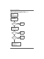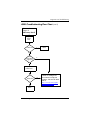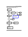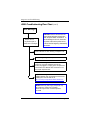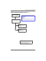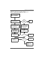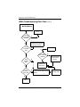
1
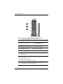
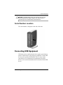
Troubleshooting Guide
HP Compaq t5000 Series Thin Client
Document Part Number: 335795-006
July 2004
© 2003, 2004 Hewlett-Packard Development Company, L.P.
HP, Hewlett Packard, and the Hewlett-Packard logo are trademarks of
Hewlett-Packard Company in the U.S. and other countries.
Compaq, and the Compaq logo are trademarks of Hewlett-Packard
Development Company, L.P. in the U.S. and other countries.
Microsoft, Windows, and Windows NT are U.S. registered trademarks of
Microsoft Corporation.
Intel, Pentium, Intel Inside, and Celeron are trademarks of Intel
Corporation in the U.S. and other countries.
Transmeta, the Transmeta logo, Crusoe, the Crusoe logo, and combinations
thereof are trademarks of Transmeta Corporation in the U.S.A. and other
countries.
All other product names mentioned herein may be trademarks of their
respective companies.
The information contained herein is subject to change without notice. The
only warranties for HP products and services are set forth in the express
limited warranty statements accompanying such products and services.
Nothing herein should be construed as constituting an additional warranty.
HP shall not be liable for technical or editorial errors or omissions
contained herein.
This document contains proprietary information that is protected by
copyright. No part of this document may be photocopied, reproduced, or
translated to another language without the prior written consent of
Hewlett-Packard Company.
Å
WARNING: Text set off in this manner indicates that failure to
follow directions could result in bodily harm or loss of life.
Ä
CAUTION: Text set off in this manner indicates that failure to follow
directions could result in damage to equipment or loss of information.
Troubleshooting Guide
HP Compaq t5000 Series Thin Client
Sixth Edition (July 2004)
First Edition (May 2003)
Document Part Number: 335795-006
Contents
Contents
1 Product Description
Network Firmware . . . . . . . . . . . . . . . . . . . . . . . . . . . . . .
HP Compaq Thin Client t5000 Series . . . . . . . . . . . . . . .
Serial Number Location . . . . . . . . . . . . . . . . . . . . . . . . . .
Connecting USB Equipment . . . . . . . . . . . . . . . . . . . . . .
Locating Additional Information . . . . . . . . . . . . . . . . . . .
1–1
1–2
1–5
1–5
1–6
2 Spare Parts Lists
t5000 Series Spare Parts List . . . . . . . . . . . . . . . . . . . . . . 2–1
3 HP t5000 Series Setup
(F10) Utility
4 Diagnostics and Troubleshooting
LEDs . . . . . . . . . . . . . . . . . . . . . . . . . . . . . . . . . . . . . . . . 4–2
Power-On Sequence . . . . . . . . . . . . . . . . . . . . . . . . . . . . . 4–3
Power-On Diagnostic Tests . . . . . . . . . . . . . . . . . . . . . . . 4–4
BIOS Error Messages. . . . . . . . . . . . . . . . . . . . . . . . . . . . 4–5
Beep Codes . . . . . . . . . . . . . . . . . . . . . . . . . . . . . . . . 4–5
Boot Error Messages . . . . . . . . . . . . . . . . . . . . . . . . . 4–7
t5000 Troubleshooting Flow Chart . . . . . . . . . . . . . . . . . 4–9
Basic Troubleshooting . . . . . . . . . . . . . . . . . . . . . . . . . . 4–26
Diskless (No-Flash) Unit Troubleshooting . . . . . . . . . . 4–30
Troubleshooting Guide
335795-006
1
Contents
5 Restoring the Flash Image
System Requirements. . . . . . . . . . . . . . . . . . . . . . . . . . . .
Getting Started . . . . . . . . . . . . . . . . . . . . . . . . . . . . . . . . .
Creating an ISO Image . . . . . . . . . . . . . . . . . . . . . . .
Formatting a USB Flash Drive . . . . . . . . . . . . . . . . .
Unpacking the Image and Tools for Deployment . . .
Deploying with PXE . . . . . . . . . . . . . . . . . . . . . . . . .
5–1
5–2
5–3
5–5
5–6
5–8
6 Citrix MetaFrame
Citrix MetaFrame Troubleshooting . . . . . . . . . . . . . . . . . 6–1
7 Microsoft Remote Desktop Protocol
A Thin Client t5000 Specifications
B Adding an Image Restore Tool Using Altiris
Deployment Solution
C Configuring a PXE Server
under Microsoft RIS
Prerequisites . . . . . . . . . . . . . . . . . . . . . . . . . . . . . . . . . . .
Installing Remote Installation Services
(RIS PXE Server) . . . . . . . . . . . . . . . . . . . . . . . . . . .
Authorizing Remote Installation Services (RIS PXE
Server) . . . . . . . . . . . . . . . . . . . . . . . . . . . . . . . . . . . .
Configuring Remote Installation Services. . . . . . . . .
Set User Permissions on the
Active Directory Server. . . . . . . . . . . . . . . . . . . . . . .
RIS Menu. . . . . . . . . . . . . . . . . . . . . . . . . . . . . . . . . .
Creating Network Bootable Disk to Map Drives . . .
For More Information . . . . . . . . . . . . . . . . . . . . . . . .
Troubleshooting Guide
335795-006
C–1
C–1
C–2
C–2
C–3
C–4
C–4
C–4
2
Contents
D System BIOS
Restoring a Corrupt BIOS . . . . . . . . . . . . . . . . . . . . . . . . D–1
Updating a BIOS . . . . . . . . . . . . . . . . . . . . . . . . . . . . . . . D–2
E Replacing the CMOS Battery
Removing and Replacing the Side Access Panel. . . . . . . E–1
Replacing the Battery. . . . . . . . . . . . . . . . . . . . . . . . . . . . E–3
F Support Information
Troubleshooting Guide
335795-006
3
Contents
4
335795-006
Troubleshooting Guide
1
Product Description
The HP Compaq Thin Client t5000 Series are Windows-based
terminals that connect over a network to a server where all
processing and storage occurs. Because of the nature of the
products, troubleshooting is significantly simpler than on a
standard PC and previous thin clients.
The Windows Graphical User Interface (GUI) is English on all
thin clients. If you are using a foreign language keyboard, you
will need to set localized settings to perform the localization
between a server-based application and the device, but interaction
with the unit itself remains in English.
Network Firmware
PXE (Pre-boot Execution Environment) is supported on all HP
Compaq Thin Client t5000 Series products.
PXE allows a client to boot from a server on a network prior to
booting the embedded Operating System (OS) from the local
Flash module. As long as the system is connected to AC power,
the Network Interface Controller (NIC) on a PXE-enabled client
remains powered even when the system is turned off. This allows
a network administrator to remotely wake up the unit and perform
various management tasks, including loading the operating
system and other software onto the device from a server over the
network.
Troubleshooting Guide
335795-006
1–1
Product Description
HP Compaq Thin Client t5000 Series
Front View of the t5000 Series Models
1Power Button
information on internal differences between the t5300, t5500,
✎ For
and t5700 series models, refer to the Getting Started with the HP
Compaq t5000 Series manual in the Reference Library at
http://h18004.www1.hp.com/products/thinclients/software.html
1–2
335795-006
Troubleshooting Guide
Product Description
Rear View of the Legacy-Free t5300 Model
Legacy-Free t5300 Model Connectors
Ä
1
Ethernet RJ-45 Connector
5
Line-out Audio Connector
(Headphone)
2
Kensington Lock Connector
6
Power Connector
3
USB Connectors
7
Monitor Connector
4
Line-in Audio Connector
(Microphone)
✎
The t5300 model does not include a PCI expansion option
connector on the system board.
CAUTION: The t5000 Series’ power cord connector is for use only
with the supplied power adaptor. Replace only with the same or
equivalent type as recommended by the manufacturer.
Troubleshooting Guide
335795-006
1–3
Product Description
Rear View of the t5500 and t5700 Series Models
t5500/t5700 Series Model Connectors
1
Ethernet RJ-45 Connector
6
Line-out Audio Connector
(Headphone)
2
Kensington Lock Connector*
7
PS/2 Connector**
3
Parallel Connector***
8
Power Connector
4
USB Connectors (4)
9
Monitor Connector
5
Line-in Audio Connector
(Microphone)
:
Serial Connector***
*When the PCI Expansion module is installed, use the connector located
at the bottom of the unit.
**Not available on all models
***Not available on t5300 series models
✎
1–4
The t5500 and t5700 series models include a PCI expansion
option connector on the system board.
335795-006
Troubleshooting Guide
Product Description
Ä
CAUTION: The t5000 Series’ power cord connector is for use only
with the supplied power adaptor. Replace only with the same or
equivalent type as recommended by the manufacturer.
Serial Number Location
The serial number is displayed on the side of the unit.
Connecting USB Equipment
USB mouse devices and keyboards do not require special drivers
and are considered to be plug and play peripherals. Certain USB
devices such as printers and modems, however, may require
special drivers. For information on requirements for special
drivers, refer to the documentation that is included with the USB
device.
Troubleshooting Guide
335795-006
1–5
Product Description
Locating Additional Information
The following documentation is available to support these
products:
■
Quick Setup
■
Hardware Reference Guide
■
Terminal Emulation Quick Reference Guide (Extended
Emulation)
■
Terminal Emulation Quick Reference Guide
■
Customer and Service Notifications, Bulletins and Advisories
■
Quickspecs
white papers, and drivers are subject to change.
✎ Documentation,
For the latest HP thin client documentation, visit the following
Web site:
http://h18004.www1.hp.com/products/thinclients/software.html
1–6
335795-006
Troubleshooting Guide
2
Spare Parts Lists
t5000 Series Spare Parts List
The Spare Parts tables that follow provide a listing of the spare
parts available for the Thin Client t5000 Series.
t5000 Series Spare Parts Table
Description
Spare Part
Number
t5300\CE .NET/IE 533MHz 32F/64R Unit
325712-001
t5300 Diskless, 533 MHz 0/64 Unit
353340-001
t5500\CE .NET/IE 733MHz 32F/128R Unit
325698-001
t5500 Diskless, 733 MHz 0/128
353341-004
t5700\XP Embedded/IE 733MHz
192/256R Unit
350982-001
t5515 800MHz 32/64Unit
370450-001
t5515 800MHz 128/128 Unit
370450-002
t5700\XP Embedded/IE 1GHz
192F/256R Unit
325707-001
t5700\XP Embedded/IE 1GHz
256F/256R Unit
325708-001
t5700 Diskless, 1GHz 0/256
353338-001
t5700 Diskless, 733MHz 0/256
353339-001
t5700, 1 GHz 192/256, XPE, IE
325707-001
AC Adapter, 12V, 40W, AC to DC
325709-001
Troubleshooting Guide
335795-006
2–1
Spare Parts Lists
t5000 Series Spare Parts Table
Description
Spare Part
Number
Mouse, USB, Carbon, 2 button scroll
323615-001
Foot Stand w/screws
336604-001
Foot, Rubber, t5000
348438-001
Battery, Internal, CR 2032, 3V
153099-001
Speaker w/screws
349326-001
Screw Kit, Miscellaneous
349327-001
Power Cords
Power Cord, AC-Europe
198292-021
Power Cord, AC-Danish
198292-081
Power Cord, International
345751-002
Power Cord, AC-Italian
198292-061
Power Cord, AC
142766-001
Power Cord, AC-PRC
292657-AA1
Power Cord AC-Japanese
292643-291
Enhanced USB Keyboards
2–2
Arabic, Carbon/Silver
326227-171
Belgian, Carbon/Silver
326227-181
Belgian, Carbonite/Silver
326228-181
Brazilian, Carbon/Silver
326227-201
Chinese (PRC), Carbon/Silver
326227-AA1
Czech, Carbon/Silver
326227-221
Danish, Carbon/Silver
326227-081
Danish, Carbonite/Silver
326228-081
Finnish, Carbon/Silver
326227-351
French, Carbon/Silver
326227-051
335795-006
Troubleshooting Guide
Spare Parts Lists
t5000 Series Spare Parts Table
Description
Spare Part
Number
Enhanced USB Keyboards (Continued)
French, Carbonite/Silver
326228-051
German, Carbon/Silver
326227-041
German, Carbonite/Silver
326228-041
Greek, Carbon/Silver
326227-151
Hebrew, Carbon/Silver
326227-BB1
Hungarian, Carbon/Silver
326227-211
International, Carbon/Silver
326227-B31
International, Carbonite/Silver
326228-B31
Italian, Carbon/Silver
326227-061
Italian, Carbonite/Silver
326228-061
Swiss, Carbon/Silver
326227-111
Japanese, Carbon/Silver
326227-291
Korean, Carbon/Silver
326227-AD1
LA Spanish, Carbon/Silver
326227-161
Norwegian, Carbon/Silver
326227-091
Portuguese, Carbon/Silver
326227-131
Russian, Carbon/Silver
326227-251
Slovakian, Carbon/Silver
326227-231
Spanish, Carbon/Silver
326227-071
Swedish, Carbonite/Silver
326228-101
Swiss, Carbonite/Silver
326228-111
Taiwan, Carbon/Silver
326227-AB1
Thailand, Carbon/Silver
326227-281
Turkey, Carbon/Silver
326227-141
Troubleshooting Guide
335795-006
2–3
Spare Parts Lists
t5000 Series Spare Parts Table
Description
Spare Part
Number
Enhanced USB Keyboards (Continued)
United Kingdom, Carbon/Silver
326227-031
United States, Carbon/Silver
326227-001
Basic USB Keyboards, Carbonite/Silver
2–4
Arabic
355631-171
Belgian
355631-181
Brazilian Portuguese
355631-201
Czech
355631-221
Danish
355631-081
Finnish
355631-351
French
355631-051
French-Canadian
355631-121
German
355631-041
Greek
355631-151
Hebrew
355631-BB1
Hungarian
355631-211
International
355631-B31
Italian
355631-061
Japanese
355631-291
Korean (Hangul)
355631-KD1
LA Spanish
355631-161
Norwegian
355631-091
Portuguese
355631-131
Russian
355631-251
Simplified Chinese
355631-AA1
335795-006
Troubleshooting Guide
Spare Parts Lists
t5000 Series Spare Parts Table
Description
Spare Part
Number
Basic USB Keyboards, Carbonite/Silver (Continued)
Slovakian
355631-231
Spanish
355631-071
Swedish
355631-111
Swiss
355631-071
Taiwanese
355631-AB1
Thai
355631-281
Turkish
355631-141
UK
355631-031
U.S.
355631-001
you are using a foreign language keyboard, an ICA or RDP
✎ Ifconnection
will perform the localization between a
server-based application and the device, but all interaction
with the thin client itself is in English.
keyboards listed in this table may not be available at the
✎ All
time this document is first published.
Options
Cradle, USB MultiBay
280879-001
Cable, USB External MultiBay Cradle
287693-001
Adapter, AC External MultiBay Cradle
287694-001
Plugs, External MultiBay Cradle
287695-001
PCI Expansion Module
336603-001
Premier•Sound speakers
173980-001
Kensington cable lock
294359-001
SODIMM, 512MB, PC2100, 32Mx8CL2.5
338802-001
Troubleshooting Guide
335795-006
2–5
Spare Parts Lists
t5000 Series Spare Parts Table
Description
Spare Part
Number
Options (Continued)
Hard Drive, 30GB
217096-001
Diskette Drive, 1.44MB
241995-001
CD-ROM Drive, 24X
228746-001
USB Flash Drive (Drive Key), 32MB
305283-001
USB Flash Drive (Drive Key), 128MB
(USB 1.1)
331466-001
USB Flash Drive (Drive Key), 128MB
(USB 2.0)
349988-001
USB Flash Drive (Drive Key), 256MB
(USB 2.0)
344249-001
✎
For a full list of supported and leveraged Hewlett-Packard and
third party options, go to
http://h18004.www1.hp.com/products/thinclients/op
tions/
2–6
335795-006
Troubleshooting Guide
3
HP t5000 Series Setup
(F10) Utility
Using HP t5000 Series Setup (F10) Utility
The Setup utility can be accessed only by turning the computer on
or restarting the system. To access the Setup Utility menu,
complete the following steps:
1. Turn on or restart the computer.
❏
If you are using Microsoft Windows XP Embedded, click
Start > Shut Down > Restart the Computer.
❏
If you are using Microsoft Windows CE .NET, click
Start > Shut Down > Shut Down and Restart > OK.
2. When the F10 = Setup message displays in the task bar at the
bottom of the screen, press the F10 key.
press the
key while the message is displayed,
✎ Ifyouyoumustdo not
restart the computer again to access the utility. When
F10
the F10 Post Screen display is set to zero seconds, it may be
necessary to press and hold F10 on the keyboard, then power on
the computer.
3. A choice of five menu headings and five task headings
appears in the Setup Utility menu:
Menu Headings: System Information, Standard CMOS
Features, Advanced BIOS Features, Integrated Peripherals,
and Power Management Setup.
Troubleshooting Guide
335795-006
3–1
HP t5000 Series Setup (F10) Utility
Task Headings: Load Factory Defaults, Set Administrative
Password, Set User Password, Save & Exit Setup, and Exit
without Saving.
4. Use the arrow (up and down, or left and right) keys to select
the appropriate heading, then press the Enter key. To return
to the Setup Utility menu, press the Esc key.
5. To apply and save changes, select Save and Exit Setup.
Ä
3–2
❏
If you have made changes that you do not want applied,
select Exit without Saving.
❏
To reset to factory settings, select Load Factory
Defaults. This option will restore the original factory
system defaults.
CAUTION: Do NOT turn the computer power OFF while the ROM is
saving your F10 Setup changes because the CMOS could become
corrupted. It is safe to turn off power to the computer ONLY after you
exit the F10 Setup screen.
335795-006
Troubleshooting Guide
HP t5000 Series Setup (F10) Utility
t5000 Series Setup Utility
Heading
Option
Description
Lists:
System
Information
• Product name
• Processor type
• Processor Speed
• CMS Version
• OEM Config Table Version
• Amount of Flash memory
• Memory size
• System ROM (includes family name
and version)
• Integrated MAC address for embedded,
enabled NIC (if applicable)
• UUID (Universal Unique ID)
• Chassis serial number
• Asset tracking number (Sets Asset tracking
number)
• Asset Tag Number
Standard
CMOS
Features
✎
Date
Allows you to set the date
Time
Allows you to set the time.
xxxMB ATA
Flash
Indicates ATA Flash settings
Halt on
Allows you to select system response when
POST Error has been detected.
Support for specific Setup options may vary depending on your
hardware configuration.
Troubleshooting Guide
335795-006
3–3
HP t5000 Series Setup (F10) Utility
t5000 Series Setup Utility (Continued)
Heading
Option
Advanced
BIOS
Features
Allows you to:
MBR Security
Choose the Virus warning feature.
Quick Power
On Self Test
Allows the system to skip certain tests while
booting so the unit has a faster boot.
First Boot
Device
Select Boot Device Priority. The default is set to
USB.
Second Boot
Device
Select Boot Device Priority
Third Boot
Device
Select Boot Device Priority
Bootup
NumLock
Status
Select Power On state for NumLock.
Security
Option
Select whether the Password is required every
time the system boots or only when you enter
Setup.
POST delay
(secs)
Set a delay that is added to POST to allow
more time to press F10 to enter the Setup
Utility.
Integrated
Peripherals
✎
3–4
Description
Allows you to:
Integrated
Audio
Enable/disable onboard AC97 audio
controller
Network
Controller
Enable/disable onboard LAN device
Support for specific Setup options may vary depending on your
hardware configuration.
335795-006
Troubleshooting Guide
HP t5000 Series Setup (F10) Utility
t5000 Series Setup Utility (Continued)
Heading
Option
Description
Integrated
Peripherals
(Cont’d)
USB Controller
Enable/disable USB controller
USB Keyboard
Support
Use USB keyboard under DOS
USB Mouse
Support
Use USB Mouse under DOS
Serial Port
Select serial port base IO port address and
IRQ
Parallel Port
Select parallel port base IO port address and
IRQ
Parallel Mode
Select parallel port transfer mode
ECP Mode
Use DMA
Select DMA channel if parallel is operated in
ECP mode.
Parallel Port
EPP Type
Select EPP type
Allows you to:
Power
Management Setup
Wake on PME
Enable/disable system wakeup capability for
onboard LAN device and PCI Card
Wake on
Alarm
Enable wakeup on RTC alarm
Load Factory Defaults
✎
Select Yes or No (Y/N)
Support for specific Setup options may vary depending on your
hardware configuration.
Troubleshooting Guide
335795-006
3–5
HP t5000 Series Setup (F10) Utility
t5000 Series Setup Utility (Continued)
Heading
Option
Set Administrative Password
Description
Allows you to set and enable the administrative
password.
✎
Set User Password
If the administrative password is set,
it is required to change the Setup
options, flash the ROM, and make
changes to certain plug and play
settings under Windows.
Allows you to set and enable the user
password.
✎
When the user password is set, it
prevents unauthorized access to the
user’s setup. User password provides
read-only access to Setup options.
Save & Exit Setup
Saves data to CMOS
Exit without Saving
Exits the Setup Utility without saving any
changes.
✎
3–6
Support for specific Setup options may vary depending on your
hardware configuration.
335795-006
Troubleshooting Guide
4
Diagnostics and Troubleshooting
information on using the Thin Client t5000 Series as an HP
✎ For
9000 or HP Integrity server console, refer to the White Paper on
http://docs.hp.com/hpux/onlinedocs/AB300-90001/AB300-90
001.pdf
Troubleshooting Guide
335795-006
4–1
Diagnostics and Troubleshooting
LEDs
Power-On LED
LED
Status
Off
When the unit is plugged into the wall socket
and the Power LED is off, the unit is powered off.
However, the network can trigger a Wake On
LAN event in order to perform management
functions.
Green
Displays during boot sequence and while the
unit is on. During boot sequence, hardware
initialization is processed and startup tests are
performed on the following:
• Processor initialization
• Memory detection and initialization
• Video detection and initialization
✎
If one of the tests fails, the unit will
simply stop, but the LED will stay on. If
the video test fails, the unit beeps.
There are no messages sent to video
for any of these failed tests.
✎
After the video is initialized, anything
that fails will have an error message.
LEDs are located inside the RJ-45 connector on the top,
✎ RJ-45
rear panel of the thin client. The LEDs are visible when the
connector is installed. Blinking green indicates network activity,
and amber indicates a 100MB speed connection.
4–2
335795-006
Troubleshooting Guide
Diagnostics and Troubleshooting
Power-On Sequence
At power-on, the flash boot block code initializes the hardware to
a known state, then performs basic power-on diagnostic tests to
determine the integrity of the hardware. Initialization performs
the following functions:
1. Initializes CPU and memory controller.
2. Initializes VGA software.
3. Initializes and configures all PCI devices.
4. Initializes the video to a known state.
5. Initializes USB devices to a known state.
6. Performs power-on diagnostics. (See the following
“Power-On Diagnostics” section.)
7. The unit boots the operating system.
Troubleshooting Guide
335795-006
4–3
Diagnostics and Troubleshooting
Power-On Diagnostic Tests
The Power-on diagnostics performs basic integrity tests of the
hardware to determine its functionality and configuration. If a
diagnostic test fails during hardware initialization the unit simply
stops. There are no messages sent to video.
may try to restart the unit and run through the diagnostic tests
✎ You
a second time to confirm the first shutdown.
The following table lists the tests that are performed on the t5000
units.
Power-On Diagnostic Test
Test
4–4
Description
Boot Block Checksum
Tests boot block code for proper
checksum value
DRAM
Simple write/read pattern test of the
first 640k of memory
Parallel port
Initiates the port’s driver and
determines if the device is present
Serial port
Tests the serial port using simple port
verification test to determine if ports
are present
Timer
Tests timer interrupt by using polling
method
RTC CMOS battery
Tests integrity of RTC CMOS battery
NAND Flash device
Tests for proper NAND flash device
ID present
335795-006
Troubleshooting Guide
Diagnostics and Troubleshooting
BIOS Error Messages
Beep Codes
A BIOS beep code indicates that a video error has occurred and
the BIOS cannot initialize the video screen to display any
additional information. This beep code consists of a single long
beep followed by two short beeps. One long beep followed by
three short beeps indicates the system is running in boot block
recovery mode. If there are no video errors, the system goes
directly to POST messages.
POST Messages
Procedures
BIOS ROM checksum error - System The checksum of the BIOS code in the
halted
BIOS chip is incorrect, indicating the
BIOS code may have become corrupt.
To restore a corrupt BIOS, refer to
Appendix D, “System BIOS” or call
your local HP Call Center for a
diagnosis. For phone numbers of an HP
Call Center near you, visit the following
Web site:
http://www.hp.com/support.
CMOS battery failed
The CMOS battery is no longer
functional. For information on replacing
the battery, refer to Appendix E,
“Replacing the CMOS Battery.”
CMOS checksum error - Defaults
loaded
Checksum of CMOS is incorrect, so the
system loads the default equipment
configuration. A checksum error may
indicate that CMOS has become
corrupt. A weak battery may have
caused this error. Replace the battery if
necessary. For more information, refer
to Appendix E, “Replacing the CMOS
Battery.”
Troubleshooting Guide
335795-006
4–5
Diagnostics and Troubleshooting
POST Messages
Procedures
CPU at nnnn
Displays the running speed of the CPU.
Press ESC to skip memory test
The user may press Esc to skip the full
memory test.
Keyboard error or no keyboard
present
Cannot initialize the keyboard. Make
sure the keyboard is attached correctly
and no keys are pressed during POST.
To purposely configure the system
without a keyboard, set the error halt
condition in Setup to HALT ON ALL,
BUT KEYBOARD. The BIOS then
ignores the missing keyboard during
POST.
Keyboard is locked out - Unlock the The message usually indicates that one
key
or more keys have been pressed during
the keyboard tests. Be sure no objects
are resting on the keyboard.
Memory Test
This message displays during a full
memory test, counting down the
memory areas being tested.
Memory Test Fail
If POST detects an error during memory
testing, additional information appears
giving specifics about the type and
location of the memory error.
Override enabled - Defaults loaded If the system cannot boot using the
current CMOS configuration, the BIOS
can override the current configuration
with a set of BIOS defaults designed for
the most stable, minimal-performance
system operations.
4–6
335795-006
Troubleshooting Guide
Diagnostics and Troubleshooting
POST Messages
Press TAB to show POST screen
Procedures
Press the TAB key during POST to
display messages hidden by the HP
logo.
Error: Non-System disk or disk error The BIOS was unable to find a suitable
boot device. For the t5000 Series, this
may mean an uninitialized or corrupt
ATA Flash. Reflash the unit and press
any key when ready. For more
information, refer to Chapter 5,
“Restoring the Flash Image.”
Boot Error Messages
Boot Error Messages
Screen Messages
Corrective Action
Bad Block Test Error Message: “The
internal diagnostics have detected a
problem.”
Too many bad flash memory blocks.
This is a hardware problem. If the
problem occurs every time the
terminal is turned on, call your local
HP Call Center for a diagnosis. For
the phone numbers of an HP Call
Center near you, visit the folowing
Web site:
http://www.hp.com/cgi-bin/hpsup
port/index.pl
Troubleshooting Guide
335795-006
4–7
Diagnostics and Troubleshooting
Boot Error Messages (Continued)
Screen Messages
Corrective Action
Flash Memory Error Message: “The
terminal’s flash file system has been
corrupted. Normally, this problem
can be corrected by reloading the
terminal’s firmware.”
• Reflash the software image if
you have already created a
recovery device or file.
• If you have not created a
recovery diskette, you must
download the appropriate
image from
http://h18004.www1.hp.c
om/products/thinclients/sof
tware.html and reflash the
terminal’s software.
✎
4–8
335795-006
For information on
reflashing software, see
Chapter 5, “Restoring the
Flash Image.”
Troubleshooting Guide
Diagnostics and Troubleshooting
t5000 Troubleshooting Flow Chart
Start
Initial Troubleshooting
Is
there
power?
N
Go to Page 4-10
No Power
N
Go to Page 4-13
No Video
N
Go to Page 4-17
Error Messages
N
Go to Page 4-18
No O/S Loading
Y
Is
there
video?
Y
Beeps,
LEDs, or error
messages ?
Y
Is
the OS
Loading?
Y
Go to next page
t5000 Troubleshooting
Flow Chart
B
Troubleshooting Guide
335795-006
4–9
Diagnostics and Troubleshooting
t5000 Troubleshooting Flow Chart (cont’d)
Continued from
Page 4-8
B
Initial Troubleshooting
Keyboard
/mouse
working?
N
Go to Page 4-20
Non-functioning
Pointing Device or
Keyboard
Y
NIC
working?
N
Go to Page 4-21
No Internal Network
Connector
N
Go to Page 4-22
No Audio
N
Go to Page 4-23
No IP address
Y
Audio
working?
Y
Windows
Desktop
displayed but
can’t connect?
Booting
in continuous
loop.
4–10
Y
335795-006
Go to Page 4-24
Booting in Continuous
Loop
Troubleshooting Guide
Diagnostics and Troubleshooting
t5000 Troubleshooting Flow Chart (cont’d)
No Power, Part 1
No Power
(Power LED is off)
Is
power cord
connected from
power source to
brick and brick
to system ?
N
Plug power cord into
brick and power source,
then from brick to system.
Y
Using
power strip
or UPS?
Y
Ensure power strip
or UPS is turned on.
N
Active
Outlet
N
Turn computer off.
Plug power cord into
different active wall
outlet.
Y
Turn off power, and
disconnect power cord.
Restart thin client
and return to
start of this chart.
Go to next page
t5000 Troubleshooting
Flow Chart
No Power, Part 2
Troubleshooting Guide
335795-006
4–11
Diagnostics and Troubleshooting
t5000 Troubleshooting Flow Chart (cont’d)
Continued from
Page 4-10
No Power, Part 2
Plug directly
into AC outlet
Power
LED on?
Y
Done
Y
Done
N
Try
different
outlet
N
Reseat AC adapter
in thin client and
at power source
Power on?
N
Power Outlet
active?
Y
Go to next page
t5000 Troubleshooting
Flow Chart
No Power, Part 3
4–12
335795-006
Troubleshooting Guide
Diagnostics and Troubleshooting
t5000 Troubleshooting Flow Chart (cont’d)
Continued from
Page 4-11
No Power, Part 3
Replace
power
cord
Power on?
Y
Done
N
Is the
power brick
light on?
Y
N
Replace the
power brick.
Power on?
Y
N
Call your local HP Call
Center for a diagnosis.
To locate a local phone
number, visit the HP Web
site at:
http://www.hp.com/cgi-bin
/hpsupport/index.pl
Done
Troubleshooting Guide
335795-006
4–13
Diagnostics and Troubleshooting
t5000 Troubleshooting Flow Chart (cont’d)
No Video, Part 1
Beeps
Go to Page 4-17
Error Messages
Y
N
Monitor
LED on?
LED
color?
(note 1)
Y
Green
Contrast
and brightness
turned up?
N
Y
Amber
N
Turn contrast
and
brightness up.
Video
adapter
connected?
(note 2)
Y
Go to Page 4- 14
No Video, Part 2
N
Plug in, turn on, and
return to page 4- 8
Initial Troubleshooting.
Go to next page
t5000 Troubleshooting
Flow Chart
No Video, Part 2
4–14
Notes:
1. Older monitors and some third
party monitors do not support
the amber LED.
2. If more than one adapter is
installed, monitor must be
connected to primary controller.
335795-006
Troubleshooting Guide
Diagnostics and Troubleshooting
t5000 Troubleshooting Flow Chart (cont’d)
Continued from
Page 4-13
No Video, Part 2
Monitor
plugged in
and turned
on?
Y
Reconnect
monitor to
thin client
(note 3)
Video OK?
Y
Done
N
N
Note:
3. Turn off and unplug
thin client before
reconnecting cables.
Plug in and turn
on monitor
Video OK?
Replace
Monitor
Y
Done
N
Does unit have added
PCI expansion or
memory upgrades?
N
Have the unit serviced.
NOTE: Refer to the
Warranty for coverage
information.
Y
Go to next page
t5000 Troubleshooting
Flow Chart
No Video, Part 3
Troubleshooting Guide
335795-006
4–15
Diagnostics and Troubleshooting
t5000 Troubleshooting Flow Chart
(cont’d)
Continued from
Page 4-14
No Video, Part 3
Turn off power,
disconnect power cord,
and open the computer.
CAUTION: Power is continuous
to the system board and power
supply even when the power
switch is turned off. To prevent
damage to the unit, disconnect
the power cord from the power
source or the unit before
beginning disassembly procedures.
Reseat flash, riser
board, and PCI memory,
then clear CMOS by
removing and replacing
the battery.
Replace cover and
power cord, then
restart computer.
Video OK,
computer
starts?
N
Y
Done
Same
symptoms?
N
Y
Y
F1-CMOS
checksum
error defaults
loaded
N
Turn off computer and disconnect power. Replace
components in system one at a time starting with
Flash. Test system after each replacement for video
or beeps.
Go to next page
t5000 Troubleshooting
Flow Chart
No Video, Part 4
4–16
CMOS
checksum error
defaults
loaded
NOTE: Remove auxiliary video
card if integrated video.
335795-006
Troubleshooting Guide
Diagnostics and Troubleshooting
t5000 Troubleshooting Flow Chart (cont’d)
Continued from
Page 4-15
No Video, Part 4
CAUTION: Power is continuous to
the system board and power supply
even when the power switch is
turned off. To prevent damage to
the unit, disconnect the power cord
from the power source or the unit
before beginning disassembly
procedures.
Restart computer
See
codes or
hear beeps ?
N
Y
Turn off computer and
disconnect power. Replace
components in system one
at a time starting with Flash.
Test system after each
replacement for video or
beeps. (see page 4-17)
Integrated
video?
Replace
video
card
N
Y
Have the unit
serviced.
N
Video OK?
NOTE: Refer to
the Warranty for
coverage information.
Y
Done
Troubleshooting Guide
335795-006
4–17
Diagnostics and Troubleshooting
t5000 Troubleshooting Flow Chart (cont’d)
Error Messages
Beeps, CPU or
Keyboard Lights, or
POST error messages.
CAUTION: Power is continuous to the
system board and power supply even
when the power switch is turned off. To
prevent damage to the unit, disconnect
the power cord from the power source
or the unit before beginning disassembly
procedures.
Power LED has no color showing. Computer is off.
Power LED glows green. Computer is on.
Beep code - 1 Long, 2 Short. Video controller not
present or incorrectly initialized. Ensure the
monitor is plugged in. Unplug, open computer and
check video card. Reseat card and ensure it is in
the proper expansion slot.
Beep code - 1 Long, 3 Short. ROM failure. Create
ROMPaq diskette and reload ROM. Download the
ROMPaq from the HP Web site at
http://www.hp.com/products/thinclientsoftware.
NOTES: Short (S) and long (L) beeps will only
be heard if the system has a speaker.
LEDs will only function on PS/2 keyboards,
not USB.
4–18
335795-006
Troubleshooting Guide
Diagnostics and Troubleshooting
t5000 Troubleshooting Flow Chart (cont’d)
No O/S Loading
Factory recommended booting priority:
1. USB Device
2. Flash
3. Network
Note: For diskless models see page 4-29.
O/S not loading from:
Flash
Go to Page 4-19
Network
Go to Page 4-21
NOTE: If USB diskette drive present
and diskette installed, system will not
boot from other USB device.
Troubleshooting Guide
335795-006
4–19
Diagnostics and Troubleshooting
t5000 Troubleshooting Flow Chart (cont’d)
O/S not loading from Flash*
* Not for diskless models
Boot
from Flash?
Using t5000 F10 Setup,
change boot priority to
factory defaults.
1. USB Device
2. Flash*
3. Network
*Check “Amount of Flash
memory” in system
information table.
Y
Done
N
Restore image using
the Recovery process
(See Chapter 5)
Boot
from Flash?
Disconnect any USB diskette
drive or USB CD-ROM drive.
Y
Done
N
Service the unit.
Press Ctrl-Alt-Del to reboot.
4–20
NOTE: Refer to the Warranty
for coverage information.
335795-006
Troubleshooting Guide
Diagnostics and Troubleshooting
t5000 Troubleshooting Flow Chart (cont’d)
Non-functioning Pointing
Device or Keyboard
Pointing device or keyboard
not operating properly.
Keyboard
or mouse
working?
Y
Done
N
Reseat USB keyboard or
mouse and disconnect
other USB devices.
F10 Setup to enable
USB controller.
Disconnect the
non-functioning device
and attach a known
working keyboard/mouse
to the system.
Press Ctrl-Alt-Del to
reboot.
Press Ctrl-Alt-Del to
reboot.
Working?
Y
Done
N
Reimage device
using the
recovery process.
Working?
Y
Done
N
Have the unit
serviced.
NOTE: Refer to the
Warranty for coverage
information.
Troubleshooting Guide
335795-006
4–21
Diagnostics and Troubleshooting
t5000 Troubleshooting Flow Chart (cont’d)
No Internal Network Connection
NOTE: Yellow or green
LED on NIC connector
indicates an active jack.
Network
or jack active?
(see Note)
NIC
configured
in OS?
N
Y
Replace cable
or have jack
activated.
Reimage using
recovery process
N
OK?
Y
Done
N
Call your local HP Call Center
for a diagnosis. To locate a
local phone number, visit the
HP Web site at:
http://www.hp.com/cgi-bin
/hpsupport/index.pl
4–22
335795-006
Troubleshooting Guide
Diagnostics and Troubleshooting
t5000 Troubleshooting Flow Chart (cont’d)
No Audio
Is Volume Control or
Media Player muted?
If so, change the setting.
Audio?
Y
Done
N
Are speaker connectors in
correct jacks? Try both
audio jacks.
Audio?
Restore image using
the Recovery process.
(See Chapter 5.)
Y
N
In Control Panel’s Sound
and Audio, does the Audio
tab indicate whether the
unit sees its audio hardware?
Audio?
Y
Done
N
N
Y
Disconnect any
external speakers.
Take the following actions:
1. Reseat speaker cable
2. Replace speaker
NOTE: Refer to Warranty for
coverage information.
N
Turn up volume for internal
and external speakers.
Troubleshooting Guide
Audio?
335795-006
Y
Done
4–23
Diagnostics and Troubleshooting
t5000 Troubleshooting Flow Chart (cont’d)
No IP Address
Done
Thin client
Y
have a valid IP
address?
N
Ping
Loopback
OK?
Service the unit.
NOTE: Refer to the Warranty
for coverage information.
N
Y
Y
Ping
Gateway
OK?
Thin client
have a valid IP
address?
N
N
Reimage device
using restore
process
Reboot unit
and server
Y
Ping
Server by
name OK?
Done
N
Contact Server Administrator
to verify DCHP, DNS services
started.
Replace
network cable
Y
Done
4–24
335795-006
Troubleshooting Guide
Diagnostics and Troubleshooting
t5000 Troubleshooting Flow Chart (cont’d)
Booting in
Continuous Loop
Using t5000 F10 Setup, change
boot priority to factory defaults.
1. USB Device
2. Flash*
3. Network
*Check “Amount of Flash memory”
in system information table.
Reboot the
thin client.
Y
Boot OK?
Service the unit.
NOTE: Refer to the Warranty
for coverage information.
N
If you are using XPe OS, disable
the write filter.
Check that Altiris 5.6 Deployment
server is being used.
Done
Y
Boot OK?
Reboot the
thin client.
Boot OK?
N
Reboot the
thin client.
Y
N
Reimage the system. Refer
to Chapter 5, “Restoring the
Flash Image.”
Troubleshooting Guide
t5000 Troubleshooting Flow Chart
End
335795-006
4–25
Diagnostics and Troubleshooting
Basic Troubleshooting
If the Thin Client t5000 Series is experiencing operating
problems or will not power on, review the following items.
Power-On Troubleshooting
Issue
Procedures
The thin client unit is experiencing
operating problems.
Ensure that the following connectors
are securely plugged into the thin
client unit:
• Power connector
• Keyboard (USB)
• Mouse (USB)
• Network RJ-45 connector
• Monitor
The thin client unit does not power
on.
1. Verify that the power supply is
good by installing it on a
known working unit and testing
it. If the power supply does not
work on the test unit, replace
the power supply.
2. If the unit does not work
properly with the replaced
power supply, have the unit
serviced.
4–26
335795-006
Troubleshooting Guide
Diagnostics and Troubleshooting
Power-On Troubleshooting (Continued)
Issue
Procedures
The thin client unit powers on and
displays a splash screen, but does
not connect to the server.
1. Verify that the network is
operating and the network
cable is working properly.
2. Verify that the unit is
communicating with the server
by having the System
Administrator ping the unit from
the server:
• If the thin client pings back,
then the signal was accepted
and the unit is working. This
indicates a configuration
issue.
• If the thin client does not ping
back and the thin client does
not connect to the server,
reimage the unit.
Troubleshooting Guide
335795-006
4–27
Diagnostics and Troubleshooting
Power-On Troubleshooting (Continued)
Issue
Procedures
No link or activity on the network
RJ-45 LEDs or the LEDs do not
illuminate blinking green after
powering on the thin client unit. (The
network LEDs are located inside the
RJ-45 connector on the top, rear
panel of the thin client. Indicator
lights are visible when the connector
is installed.)
1. Verify that the network is not
down.
2. Make sure the RJ-45 cable is
good by installing the RJ-45
cable onto a known working
device—if a network signal is
detected then the cable is
good.
3. Verify the power supply is good
by replacing the power cable to
the unit with a known working
power supply cable and testing
it.
4. If network LED's still do not light
and you know the power supply
is good, then reimage the unit.
5. If network LED’s still do not
light, run the IP configuration
procedure on page 4-23.
6. If network LED’s still do not
light, have the unit serviced.
A newly connected unknown USB
peripheral does not respond or USB
peripherals connected prior to the
newly connected USB peripheral will
not complete their device actions.
4–28
335795-006
An unknown USB peripheral may be
connected and disconnected to a
running platform as long as you do
not reboot the system. If problems
occur, disconnect the unknown USB
peripheral and reboot the platform.
Troubleshooting Guide
Diagnostics and Troubleshooting
Power-On Troubleshooting (Continued)
Issue
Procedures
Video does not display.
1. Verify that the monitor
brightness is set to a readable
level.
2. Verify the monitor is good by
connecting it to a known
working computer and ensure
its front LED turns green
(assuming the monitor is Energy
Star compliant). If the monitor is
defective, replace it with a
working monitor and repeat
testing.
3. Reimage the thin client unit and
power on the monitor again.
4. Test the thin client unit on a
known working monitor. If the
monitor does not display video,
replace the thin client unit.
Troubleshooting Guide
335795-006
4–29
Diagnostics and Troubleshooting
Diskless (No-Flash) Unit
Troubleshooting
This section is only for those units that do not have ATA Flash
capability.
Because there is no ATA Flash in this model the boot priority
sequence is:
◆
USB device
◆
PXE
1. When the unit boots, the monitor should display the
following information:
■
MAC Address — NIC portion of the system board is OK
■
GUID—General system board information
■
Client ID—Information from server
■
MASK—Information from server
■
DHCP IP—Information from server
❏
If there is no MAC Address, the system board is at fault.
Contact the Call Center for service.
❏
If there is not GUID information, the system board is at
fault and should be replaced.
❏
If there is no Client ID, MASK, and DHCP IP
information there is no network connection. This may be
caused by a bad cable, the server is down, or a bad system
board. Contact the Call Center for service for the bad
system board.
If you are running in an MS RIS PXE environment go to
step 2.
If you are running in a Linux environment go to step 3.
4–30
335795-006
Troubleshooting Guide
Diagnostics and Troubleshooting
2. If you are running in an MS RIS PXE environment press the
F12 key to activate the network service boot as soon as the
DHCP IP information appears on the screen.
❏
If the unit does not boot to the network the server is not
configured to PXE.
❏
If you missed the F12 cue, the system will try to boot to
the ATA flash that is not present. The message on the
screen will read:
ERROR: Non-system disk or disk error. Replace and press
any key when ready.
❏
Pressing any key will restart the boot cycle.
3. If you are running in a Linux environment an error message
will appear on the screen if there is no Client IP.
ERROR: Non-system disk or disk error. Replace and press
any key when ready.
Troubleshooting Guide
335795-006
4–31
Diagnostics and Troubleshooting
4–32
335795-006
Troubleshooting Guide
5
Restoring the Flash Image
System Requirements
To create a recovery device for the purpose of reflashing or
restoring the software image on the ROM, you will need the
following:
■
A personal computer running Microsoft Windows 2000
Professional or Microsoft Windows XP Professional
■
One or more HP Compaq t5000 Series Thin Clients
■
CD-R or CD-RW drive (if using the ISO Image option)
■
USB flash device 32MB for Microsoft Windows CE .NET or
256MB for Windows XP Embedded (if using the USB
format). Compatible USB flash devices (drive keys) are
available from www.diskonkey.com.
This restore method will not work with all USB flash
devices. USB flash devices with multiple partitions generally
do not support this restore method. The range of USB flash
devices available on the market is constantly changing. Not
all USB flash devices (drive keys) have been tested with the
HP Compaq Thin Client Imaging Tool.
■
USB CD-ROM drive for thin client (if using the ISO Image
option)
Before using the utility, you must download the appropriate
image from http://www.hp.com/products/thinclientsoftware.
Troubleshooting Guide
335795-006
5–1
Restoring the Flash Image
Getting Started
There are three deployment options supported by this utility. You
can choose to do one or more of the following using your
personal computer:
■
Generate an ISO image to use with CD creation software to
create a bootable CD for deployment using a USB CD-ROM
drive.
■
Create a bootable flash image on a USB flash device (such as
a drive key)
■
Unbundle the image to a directory for use in a custom
deployment scenario or PXE image.
Download and run the Package-for-the-Web deliverable (an .exe
file) that contains the original factory image for the thin client.
The HP Compaq Thin Client Imaging Tool (CRStart.exe) runs
automatically and will display the following dialog:
Choose one of the deployment options: ISO Image, USB Format,
or Deployment. Each option is described in the following
paragraphs.
5–2
335795-006
Troubleshooting Guide
Restoring the Flash Image
During the restore process, the thin client flash drive will be
reformatted and all data on it will be erased before the system
image is copied to it. To prevent loss of data, be sure that you
have saved any user-created data from the flash drive.
During the first restart of the thin client following the restore
process, it may take approximately 15 minutes to unbundle
the software before the Windows Desktop is displayed.
Creating an ISO Image
1. Click ISO Image.
2. When prompted, enter a file name for the generated ISO file.
Troubleshooting Guide
335795-006
5–3
Restoring the Flash Image
Once this process is complete, use the generated ISO file to create
a bootable restore CD with your CD creation software.
3. Connect a USB CD-ROM drive to the thin client. Only one
bootable USB device may be attached to the thin client
during this process.
4. Insert the bootable restore CD into the CD-ROM drive.
5. Restart the thin client.
6. When prompted Do you want to continue? [Y/N] click Y to
begin the image restore process on the thin client.
5–4
335795-006
Troubleshooting Guide
Restoring the Flash Image
Formatting a USB Flash Drive
Ä
CAUTION: To prevent loss of data, be sure that you have saved any
user-created data from the USB drive to another drive.
1. Connect your USB flash device (drive key) to your personal
computer. Ensure that only one USB flash device is
connected to the system.
2. Click USB Format.
3. Select the USB drive from the list, using the up and down
arrows to display the correct drive letter. (If the USB drive
does not appear in the list, click Update Drives, then scroll
through the list again.)
During the next step, the USB drive will be reformatted and
all data on it will be erased before the bootable image is
copied to it. To prevent loss of data, be sure that you have
saved any data from the USB drive to another drive.
Troubleshooting Guide
335795-006
5–5
Restoring the Flash Image
4. Click Format.
5. Connect the bootable USB flash device to the thin client.
Only one bootable USB device may be attached to the thin
client during this process.
6. Restart the thin client.
7. When prompted Do you want to continue? [Y/N] click Y to
begin the image restore process on the thin client.
Unpacking the Image and Tools for
Deployment
1. Click Deployment.
2. When prompted, select the destination directory for the
imaging tools and image.
5–6
335795-006
Troubleshooting Guide
Restoring the Flash Image
The components that comprise DSKIMG.BIN are then
unbundled. When this process is complete, there will be three
new files: IBR.EXE (the image restoration utility),
FLASH.IMG (the OS image), and README.TXT.
Troubleshooting Guide
335795-006
5–7
Restoring the Flash Image
Deploying with PXE
1. Ensure that IBR.exe and Flash.img are stored in the same
directory on the server.
2. Add [full path]\IBR.exe -y [full path]\Flash.img hd0 to the
PXE command file, and run it.
To view the IBR command line options:
At the command prompt, type IBR.EXE /? and press Enter.
Refer to "Appendix C: Configuring a PXE Server" for
instructions on setting up a PXE Server using Microsoft RIS. See
your documentation if using a different PXE server, such as
Altiris Deployment Solution.
5–8
335795-006
Troubleshooting Guide
6
Citrix MetaFrame
Citrix MetaFrame Troubleshooting
Troubleshooting section is not intended to enable HP or
✎ This
Compaq Service to support Citrix software. All Citrix software is
supported by Citrix or Citrix authorized service providers on a
warranty or service contract basis. Customers that call the HP or
Compaq Customer Service Center with Citrix issues and
questions should be referred to Citrix for assistance.
A frequently encountered issue is the inability of the Thin Client
to connect to the Citrix server. The problem is often caused by
using the server name but not having a DNS server configured on
the network or on the terminal. To correct the problem, do one of
the following:
■
Configure a DNS server on the network, then add the
necessary DNS information at the terminal.
■
Specify the server by its IP address rather than by its name.
Troubleshooting Guide
335795-006
6–1
Citrix MetaFrame
Citrix Error Messages
Error Message
Meaning
The option option is not valid.
Missing argument for option option.
The option option has an invalid
argument: argument.
The configuration file has been edited
directly or is corrupt. Reconfigure Citrix
MetaFrame.
Error in configuration file: file cannot find section section.
The configuration file has been edited
directly or is corrupt. Reconfigure Citrix
MetaFrame.
Error in configuration file. section
must contain an entry entry.
Invalid ICA Protocol data received.
This probably indicates a network error.
Cannot open visual: ID number.
This visual (ID =...) cannot support the
required number of colors.
Cannot allocate sufficient colors.
Continuing in 16-color mode.
A suitable visual has been found but it
can only support 16 colors.
Cannot find a suitable visual on
this display.
Unable to allocate a private color map
on this display.
An error occurred in the graphics
system.
This message indicates a problem with
the display. Try exiting other applications, such as Microsoft Internet
Explorer, to release the colors on your
display.
Cannot find keyboard mapping file
file.
The keyboard mapping file specified in
the Preferences page of the Settings
dialog box is invalid or cannot be
located.
A server must be entered.
A server name must be entered on the
Network page of the Properties dialog
box.
6–2
335795-006
Troubleshooting Guide
Citrix MetaFrame
Citrix Error Messages (Continued)
Error Message
Meaning
Window size must be between 300
and 2048.
The Custom Width and Height fields
on the Window page of the Properties
dialog box can take values between 300
and 2048 only.
Data has been changed. Are you
sure you want to quit?
You are quitting from the ICA client without saving changes to the current connection entry.
Cannot write file: file.
This message indicates a problem with
saving or creating a connection database (for example, no disk space).
Invalid Error: Cannot start Wfica
with this connection.
The connection entry is invalid.
Cannot find selected connection,
or cannot find specified connection.
The configuration file is corrupt. Create
a new configuration file.
Error in configuration file: file Missing section: section
The configuration file is corrupt. Create
a new configuration file.
Inconsistency in configuration file:
file Missing section: section
The configuration file is corrupt. Create
a new configuration file.
This description is already in use.
The Description must be unique.
The Description field on the Network
page of the Properties dialog box must
be unique.
Cannot get address for server
server.
The server name cannot be resolved.
Unable to perform update: client is
not on local file system.
The client cannot update an installation
on a non-local (for example, NFSmounted) file system.
Unable to perform update: Not running $ICAROOT/wfica.
The client cannot update an installation
other than its own.
Troubleshooting Guide
335795-006
6–3
Citrix MetaFrame
6–4
335795-006
Troubleshooting Guide
7
Microsoft Remote Desktop
Protocol
Microsoft Remote Desktop Protocol (RDP) is designed to
provide remote display and input capabilities over network
connections for Windows-based applications running on a server.
RDP services are accessed by the Terminal Services client
application on the thin client. RDP can be made available on the
network using any of the following services:
■
Microsoft Windows 2000 Server with Terminal Services
installed:
■
Microsoft Windows NT 4.0 Terminal Server Edition
■
Microsoft Windows XP Professional
■
Microsoft Windows .NET Server
For more information on RDP, visit the following Microsoft Web
sites:
■
http://www.microsoft.com/windowsxp/expertzone/columns/rus
sel/02January28.asp
■
http://www.microsoft.com/windows2000/technologies/terminal
/default.asp#section1
Troubleshooting Guide
335795-006
7–1
Microsoft Remote Desktop Protocol
7–2
335795-006
Troubleshooting Guide
A
Thin Client t5000 Specifications
Specifications
Item
Description
Processor
Transmeta Crusoe high-speed CPU with
on-board SDRAM controller and PCI bus controller
Memory
Memory may be expandable. Refer to
http://h18000.www1.hp.com/products/q
uickspecs/productbulletin.html for the latest
information.
Protocol
Integrated Microsoft RDP and Citrix ICA protocols and terminal personalities standard
Display Support
VESA Monitor support; scalable video up to
1600 x 1200, 16-bit color, up to 85-Hz refresh
rate.
Audio
Output: 1/8-inch mini-plug, full 16-bit stereo,
44-KHz sample rate
Input: 1/8-inch mini-plug for microphone
Input Output
Peripheral support
Keyboard: HP Enhanced USB with Microsoft
Windows keys (104 keys) included
Mouse: HP USB scroll mouse included
Printer: Local and/or network printers on ICA
(virtual port redirection ready)
Video: VGA-type video output (DB-15)
Troubleshooting Guide
335795-006
A–1
Thin Client t5000 Specifications
Specifications
Item
Networking
Description
• TCP/IP with DNS and DHCP; Point-to-Point
Protocol (PPP)
• Multiple master browser support and Citrix
load balancing on ICA
• SNMP support allows configuration of
terminal settings, reporting of terminal
configuration and attached devices, and
traps
• DHCP support for automatic firmware
upgrades and unit configuration
Administrative
Software
• Altiris Deployment Solution 5.6 or greater
Communications
• Four USB ports
• 10/100BaseT Fast Ethernet, twisted pair
(RJ45)
• ICA Remote dial-up via external modem
Terminal Personalities Supported
Refer to
http://h18000.www1.hp.com/products/q
uickspecs/productbulletin.html for the latest
information.
Resident Operating Systems
Server Compatibility
t5000 Series models may have one of the following operating systems: Microsoft Windows
CE .NET/IE or XP Embedded/IE for Thin Clients
• Microsoft Windows NT Server 4.0
• Terminal Server Edition
• Microsoft Windows 2000 Server with
Terminal Services installed
• Citrix WinFrame
• Citrix MetaFrame
A–2
335795-006
Troubleshooting Guide
B
Adding an Image Restore Tool
Using Altiris Deployment
Solution
1. Ensure that IBR.exe (Image Restore) and Flash.img are
stored in the same directory on the server (e.g., c:\program
files\altiris\express\deployment server\tcimage).
2. From the Altiris Deployment Server Console, click File >
New > Job.
3. Enter a unique name for the job that you will use to deploy
the original thin client image.
4. Click the name of the new job.
5. Near the upper right side of the screen, click Add>>.
6. Select Run Script… from the pop-up menu.
7. Enter [full path]\IBR.exe -y [full path]\Flash.img hd0
8. Under In which OS would you like to run this script?
Click DOS.
9. Click Finish.
10. You can now drag and drop the job onto the appropriate
machine(s) or schedule it to run later, depending on your
needs. Refer to the documentation for Altiris Deployment
Solution (http://www.altiris.com/support/documentation) for
more detailed information.
Troubleshooting Guide
335795-006
B–1
Adding an Image Restore Tool Using Altiris Deployment Solution
B–2
335795-006
Troubleshooting Guide
C
Configuring a PXE Server
under Microsoft RIS
Prerequisites
The services listed below must be running, and they may be
running on different servers:
1. Domain Name Service (DNS)
2. Active Directory
3. DHCP
4. Remote Installation Services (RIS) on Microsoft Windows
2000 Server
This documentation covers RIS setup, and assumes that servers 1,
2, and 3 (above) are already set up.
The RIS PXE Server must be equipped with two or more hard
drives. Remote Installation Services and Windows 2000 Server
cannot be installed on the same drive; nor will RIS work on a
double partition of Windows 2000 Server. The drive on which
RIS is installed must be first be formatted using NTFS.
Installing Remote Installation Services
(RIS PXE Server)
1. From the Windows 2000 Server, log on to the domain using
an account that has Administrator privileges on the server.
Troubleshooting Guide
335795-006
C–1
Configuring a PXE Server under Microsoft RIS
2. From the Windows Control Panel, double-click on
Add/Remove Programs.
3. Double-click Add/Remove Windows Components.
4. Select Remote Installation Services, then click Next. (Insert
Windows 2000 Server CD into the CD-ROM drive, if
prompted.)
5. Restart the computer after the wizard has finished installing
the service.
Authorizing Remote Installation Services
(RIS PXE Server)
If you have installed RIS on a server other than the server
running DHCP, authorize PXE with DHCP as follows:
1. Record the IP address of the RIS PXE Server.
2. Log on to the DHCP Server as administrator.
3. From the Control Panel, double-click Administrative Tools.
4. Double-click DHCP.
5. Right-click DHCP (just above the domain name) and select
Manage Authorized Servers.
6. Click Authorize.
7. Type the IP address of your RIS PXE server and click OK.
8. Click OK.
9. Log off from the DHCP Server.
Configuring Remote Installation Services
Use the default option to have RIS install on second hard drive
(D:\ or E:\).
1. Click Start > Run.
C–2
335795-006
Troubleshooting Guide
Configuring a PXE Server under Microsoft RIS
2. Type Risetup.exe and click Next.
3. Click Next.
4. Click the checkbox labeled Respond to client computers
requesting service.
5. Click Next.
6. Insert the Windows 2000 Professional CD into the CD-ROM
drive and enter the path to the CD-ROM drive (usually drive
D:\ or E:\).
7. Click Next.
8. Click Next.
9. Click Next.
10. When installation is complete, click Finish.
Set User Permissions on the
Active Directory Server
On the active directory server,
1. Click Start > Programs > Administrative Tools.
2. Click Active Directory Users and Computers.
3. Right-click on the appropriate domain name.
4. Click Delegate Control.
5. Click Next.
6. Click Add to add users.
7. Highlight Everyone and click Add.
8. Click OK.
9. Click Next.
10. Select Join a Computer to the Domain.
Troubleshooting Guide
335795-006
C–3
Configuring a PXE Server under Microsoft RIS
11. Click Next.
12. Click Finish.
RIS Menu
1. Install the RIS menu of your choice.
2. Configure the RIS menu.
3. Refer to the help file provided by the RIS menu for
instructions on creating a network bootable diskette and RIS
menu for PXE.
Creating Network Bootable Disk to Map
Drives
Create a network boot disk to map drives. (Refer to Microsoft
Web site for instructions on creating a network bootable diskette.)
For More Information
HP Compaq t5000 Series Documentation (including white papers
discussing software deployment methods):
http://h18004.www1.hp.com/products/thinclients/software.html
Altiris Deployment Solution Documentation:
http://www.altiris.com/support/documentation/
C–4
335795-006
Troubleshooting Guide
D
System BIOS
Restoring a Corrupt BIOS
If the BIOS code on the thin client is corrupt (see the section on
BIOS Error Messages in Chapter 4, “Diagnostics and
Troubleshooting”), the BIOS must be restored before the thin
client will boot to the operating system. To restore the BIOS on a
thin client t5000 Series, you will need the following:
■
An external USB diskette drive connected to the thin client
■
HP Compaq Thin Client t5000 Series System BIOS Softpaq
(SP23411 or the most current Softpaq) on diskette
thin client with a corrupt BIOS will only boot from a USB
✎ Adiskette
drive.
To restore a corrupt BIOS, complete the following instructions:
1. Insert an empty diskette into a diskette drive on a working
computer, and navigate to the following HP Web site:
http://h18004.www1.hp.com/products/thinclients/software.ht
ml
2. Select the Thin Client t5000 Series Softpaq (SP23411 or the
most current Softpaq) and download to your hard drive. The
file that is downloaded is an executable file.
3. From your hard drive, open the Softpaq, then open the Flash
Diskette folder and double-click the 786w2.bat file.
Troubleshooting Guide
335795-006
D–1
System BIOS
The screen prompts: Place Destination disk in drive A:,
Press any key when you are ready.
4. Be sure you have inserted an empty diskette in drive A: and
press any key to copy the software to the diskette.
5. Power off the thin client with the corrupt BIOS.
6. Connect the external USB diskette drive to the thin client and
insert the newly created Flash diskette into the diskette drive.
powering on the thin client, check to make sure there are
✎ Before
no other USB devices connected to the thin client. If there are,
disconnect them.
7. Power on the thin client.
8. At power on, the BIOS is automatically restored from the
diskette.
Å
WARNING: DO NOT TURN OFF POWER OR ATTEMPT TO
REBOOT THE THIN CLIENT DURING THE RECOVERY PROCESS.
While this procedure is primarily used to recover systems with
corrupt BIOS, it can also be used to locally update a system
BIOS.
Updating a BIOS
To update the system BIOS on the Thin Client t5000 Series,
download the Thin Client t5000 Series Softpaq (SP23411 or the
most current Softpaq) from the HP Web site at:
http://h18004.www1.hp.com/products/thinclients/software.html
D–2
335795-006
Troubleshooting Guide
System BIOS
The Softpaq contains utilities for restoring or updating the system
BIOS on the Thin Client t5000 Series. Included in the Softpaq are
several methods for changing or updating the BIOS version on
your computer. The tools and appropriate BIOS images are
contained in the following Softpaq directories:
■
DOS Flash—DOS utility that can be used locally or with a
Probate eXecution Environment (PXE) management
application to update the system BIOS.
■
WFlash—Windows-based utility used to locally update the
system BIOS on individual PCs through the Windows
environment.
To determine the BIOS family, version, and date on the thin
client, press F10 during system power-on to run the F10 Setup
utility, then select System Information.
To update the system BIOS, complete the following instructions:
1. Download the Softpaq to a directory on your hard drive. The
downloaded file is a self-extracting executable with a file
name based on the thin client model.
2. From that drive and directory, execute the desired folder from
the downloaded file and follow the on-screen instructions.
3. Copy the appropriate utility to a diskette to transfer to the thin
client.
Å
WARNING: DO NOT TURN OFF POWER OR ATTEMPT TO
REBOOT THE COMPUTER DURING THE UPGRADE PROCESS.
Troubleshooting Guide
335795-006
D–3
System BIOS
D–4
335795-006
Troubleshooting Guide
E
Replacing the CMOS Battery
Removing and Replacing the Side
Access Panel
To replace the CMOS battery, you must remove the side access panel
and chassis cover as shown below and on the next page.
Å
WARNING: Before removing the side access panel, ensure that the
thin client is turned off and that the power cord is disconnected from
the electrical outlet.
1. Remove the two back panel screws 1.
2. Pull the side panel off 2.
Removing the Side Access Panel
Troubleshooting Guide
335795-006
E–1
Replacing the CMOS Battery
3. Remove the chassis cover by removing the two screws 1 and
pulling the chassis cover 2 off.
4. Disconnect the speaker cable 3 from the system board.
Removing the Chassis Cover and Disconnecting the Speaker
E–2
335795-006
Troubleshooting Guide
Replacing the CMOS Battery
Replacing the Battery
1. Locate the battery on the system board.
2. Pull back on the clip 1 that is holding the battery in place,
and remove the battery 2.
3. Insert the new battery and position the clip back into place.
Removing and Replacing the CMOS Battery
After replacing the battery, replace the side panel and chassis cover by
reversing the previous steps.
Troubleshooting Guide
335795-006
E–3
Replacing the CMOS Battery
E–4
335795-006
Troubleshooting Guide
F
Support Information
The following URLs point to thin client support information
listed on the HP Web site.
■
http://h18004.www1.hp.com/products/thinclients/ Links to
information on the Support Home index, product
documentation, Operating System upgrades and SoftPaqs,
customer announcements and notifications, and self-help
■
http://www.hp.com/products/thinclientsoftware/ - Links to
thin client SoftPaqs and documentation
The following URLs point to embedded operating system
information listed on the Microsoft Web site:
■
http://www.microsoft.com/windows/embedded/default.asp embedded home pointer
■
http://www.microsoft.com/windows/embedded/ce.net/ CE.NET pointer
■
http://www.microsoft.com/windows/embedded/ce.net/default.a
sp - CE.NET Technical Resources pointer
■
http://www.microsoft.com/windows/embedded/xp/default.aspXPE pointer
■
http://www.microsoft.com/windows/embedded/xp/techinfo/
default.asp - XPE Technical Resources pointer
The following URLs point to Altiris software support:
■
http://www.altiris.com/ - Lifecycle Management Software
■
http://www.altiris.com/support/complimentary/ - Altiris
Complimentary Support
Troubleshooting Guide
335795-006
F–1
Support Information
The following URL points to Citrix support and services:
■
F–2
http://www.citrix.com/site/SS/index.asp - Citrix Knowledge
Center
335795-006
Troubleshooting Guide