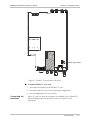
1
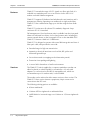
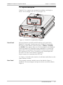
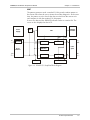
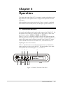
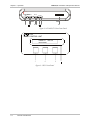
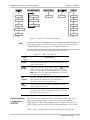
FOMi-E1/T1
High Speed Fiber Optic Modem
Installation and Operation Manual
Notice
This manual contains information that is proprietary to RAD Data Communications. No part of this
publication may be reproduced in any form whatsoever without prior written approval by RAD Data
Communications.
No representation or warranties for fitness for any purpose other than what is specifically mentioned in
this manual is made either by RAD Data Communications or its agents.
For further information contact RAD Data Communications at the address below or contact your local
distributor.
RAD Data Communications
Headquarters
12 Hanechoshet Street
Tel Aviv 69710 Israel
Tel: 972-3-6458181
Fax: 972-3-6498250
E-mail: [email protected]
RAD Data Communications
US East
900 Corporate Drive
Mahwah, NJ 07430 USA
Tel: (201) 529-1100
Fax: (201) 529-5777
E-mail: [email protected]
© 2000 RAD Data Communications
RAD Data Communications
US West
3631 South Harbor Boulevard
Suite 250
Santa Ana, CA 92704
Tel: (714) 850-0555
Fax: (714) 850-1555
Publication No. 317-200-01/00
Warranty
This RAD product is warranted against defects in material and workmanship for a period of one year
from date of shipment. During the warranty period, RAD will, at its option, either repair or replace
products which prove to be defective. For warranty service or repair, this product must be returned to
a service facility designated by RAD. Buyer shall prepay shipping charges to RAD and RAD shall pay
shipping charges to return the product to Buyer. However, Buyer shall pay all shipping charges, duties
and taxes for products returned to RAD from another country.
Limitation of Warranty
The foregoing warranty shall not apply to defects resulting from improper or inadequate maintenance
by Buyer, Buyer-supplied firmware or interfacing, unauthorized modification or misuse, operation
outside of the environmental specifications for the product, or improper site preparation or
maintenance.
Exclusive Remedies
The remedies provided herein are the Buyer’s sole and exclusive remedies. RAD shall not be liable for
any direct, indirect special, incidental, or consequential damages, whether based on contract, tort, or
any legal theory.
Safety Warnings
The exclamation point within a triangle is intended to warn the operator or
service personnel of operation and maintenance factors relating to the
product and its operating environment which could pose a safety hazard.
Always observe standard safety precautions during installation, operation and maintenance of this
product. Only a qualified and authorized service personnel should carry out adjustment, maintenance
or repairs to this instrument. No adjustment, maintenance or repairs should be performed by either the
operator or the user.
Laser Warnings
This product may be equipped with a laser diode. In such a case, this laser
warning symbol label will be attached near the optical transmitter. Please
observe the following precautions:
•
Do not attempt to adjust the laser drive current.
•
Do not use broken or unterminated fiber-optic cables/connectors or stare at the laser beam.
•
The use of optical equipment with this product will increase eye hazard.
•
Use of controls, adjustments or performing procedures other than those specified herein, may
result in hazardous radiation exposure.
Telecommunication Safety
The safety status of each of the ports on the FOMi-E1/T1 is declared according to EN 41003 and is
detailed in the table below:
Ports
Safety Status
E1, T1 (electrical)
SELV
Circuit operating with Safety Extra-Low Voltage
Regulatory Information
FCC-15 User Information
This equipment has been tested and found to comply with the limits of the Class A digital device,
pursuant to Part 15 of the FCC rules. These limits are designed to provide reasonable protection against
harmful interference when the equipment is operated in a commercial environment. This equipment
generates, uses and can radiate radio frequency energy and, if not installed and used in accordance
with the instruction manual, may cause harmful interference to the radio communications. Operation
of this equipment in a residential area is likely to cause harmful interference in which case the user will
be required to correct the interference at his own expense.
Warning per EN 55022
This is a Class A product. In a domestic environment, this product may cause radio interference, in
which case the user may be required to take adequate measures.
Declaration of Conformity
Manufacturer’s Name:
RAD Data Communications Ltd.
Manufacturer’s Address:
12 Hanechoshet St.
Tel Aviv 69710
Israel
declares that the product:
Product Name:
FOMi-E1/T1
Conforms to the following standard(s) or other normative document(s):
EMC:
Safety:
EN 55022 (1994)
Limits and methods of measurement of radio disturbance
characteristics of information technology equipment.
EN 50082-1 (1992)
Electromagnetic compatibility - Generic immunity standards
for residential, commercial and light industry.
EN 60950 (1992/93) Safety of information technology equipment, including
electrical business equipment.
Supplementary Information:
The product herewith complies with the requirements of the EMC Directive 89/336/EEC and the
Low Voltage Directive 73/23/EEC. The product was tested in a typical configuration.
Tel Aviv, November 18th, 1998
Haim Karshen
VP Quality
European Contact: RAD Data Communications GmbH, Lyoner Strasse 14, 60528 Frankfurt am Main, Germany
Quick-Start Guide
If you are familiar with fiber optic modems, use this guide to prepare
FOMi-E1/T1 for operation.
QS.1 Installing FOMi-E1/T1
For most normal installations, setup of FOMi-E1/T1 should be performed in
the following order (see Chapters 2 and 3 for details of each procedure):
Warning
Jumper Setting
Setup
Configuration via
Front Panel
Alarms Check
Make sure that the AC power cord is disconnected before removing the
unit's cover.
1.
Remove the internal board.
2.
Set Cable Type jumper as required (75Ω unbalanced for E1, 120Ω
balanced for E1 or 100Ω balanced for T1) (see section 2.4 for details).
3.
Replace the board and close the unit.
1.
Install the unit in a rack (optional, see Appendix A for details).
2.
Disconnect the cables from the units.
1.
Configure modem with remote modem details (see Chapter 3).
2.
Connect the units to the DTEs.
3.
Configure the DTE parameters.
4.
Configure the Line parameters.
Make sure that there are no alarms indicated on the LCD.
QS.2 Operating FOMi-E1/T1
Connections
1.
Connect the fiber optic cables.
2.
Connect the power cable.
FOMi-E1/T1 is turned on automatically upon connection to a power
source.
3.
If there is an indication of a malfunction or fault, run the appropriate
tests (see Chapter 4).
FOMi-E1/T1 Quick Start Guide
1
Quick-Start Guide
2
Operating FOMi-E1/T1
FOMi-E1/T1 Installation & Operation Manual
Preface
Foreword
This manual provides information on the technical characteristics, installation and operating
instructions of FOMi-E1/T1. The manual contains the following information:
Chapter 1. Introduction
Describes the FOMi-E1/T1, the versions available, features and options. Briefly
describes the Front Panel, LEDs, jumpers, connectors and fuses. This chapter also
provides a basic functional description of the FCD-T1 and a short description of some
of the main operations and options.
Chapter 2. Installation
Explains how to install the FOMi-E1/T1. Explains how to perform all the connections
needed to setup the FOMi-E1/T1. Explains how to set the jumpers and switches.
Chapter 3. Operation
Describes the controls, indicators and functions of the FOMi-E1/T1. Explains how to
operate the FOMi-E1/T1.
Chapter 4. Troubleshooting
Describes the diagnostic tests provided by the FOMi-E1/T1. Explains how to operate
the Internal BER Tester and Pattern Generator. Explains the various alarms and real
time messages that may be encountered. Outlines trobleshooting procedures.
Chapter 5. Sample Application
This chapter illustrates the configuration and setup of a typical application of the
FOMi-E1/T1.
Conventions
Note
Caution
Warning
A note draws attention to a general rule for a procedure, or to
exceptions to a rule.
A caution warns of possible damage to the equipment if a
procedure is not followed correctly.
A warning alerts to the presence of important operating and
maintenance (servicing) instructions in the literature
accompanying the equipment. If these instructions are not
followed exactly, possible bodily injury may occur.
Contents
QUICK-START GUIDE
QS.1 Installing FOMi-E1/T1......................................................................................................1
Jumper Setting ......................................................................................................................... 1
Setup....................................................................................................................................... 1
Configuration via Front Panel ................................................................................................... 1
Alarms Check........................................................................................................................... 1
QS.2 Operating FOMi-E1/T1....................................................................................................1
Connections ............................................................................................................................ 1
CHAPTER 1. INTRODUCTION
1.1 Overview ....................................................................................................................... 1-1
General Description.............................................................................................................. 1-1
Application ........................................................................................................................... 1-1
Features................................................................................................................................ 1-2
Versions................................................................................................................................ 1-2
1.2 Physical Description ....................................................................................................... 1-3
Front Panel ........................................................................................................................... 1-3
Rear Panel ............................................................................................................................ 1-3
1.3 Functional Description ................................................................................................... 1-4
General ................................................................................................................................ 1-4
Main Principles of Operation ................................................................................................ 1-4
1.4 Technical Specifications ................................................................................................. 1-6
Electrical Interface................................................................................................................. 1-6
Power................................................................................................................................... 1-6
Optical Interface ................................................................................................................... 1-6
Range ................................................................................................................................... 1-6
General Indicators................................................................................................................. 1-7
Diagnostics ........................................................................................................................... 1-7
Controls and Displays............................................................................................................ 1-8
Physical Dimensions ............................................................................................................. 1-8
Environment ......................................................................................................................... 1-8
CHAPTER 2. INSTALLATION & SETUP
2.1 Site Requirements and Prerequisites .............................................................................. 2-1
Power................................................................................................................................... 2-1
Ambient Requirements ......................................................................................................... 2-1
2.2 Package Contents........................................................................................................... 2-1
2.3 Equipment Needed........................................................................................................ 2-2
2.4 Jumper Setting ............................................................................................................... 2-2
Connecting the Interfaces...................................................................................................... 2-3
Connecting the Power........................................................................................................... 2-5
Fuse ..................................................................................................................................... 2-6
2.5 Initial Operation and Basic Checks................................................................................. 2-6
FOMi-E1/T1 Installation and Operation Manual
iii
Contents
Power-On Procedure ............................................................................................................ 2-6
Normal Operating Indications ............................................................................................... 2-6
Power-Off Procedure ............................................................................................................ 2-6
CHAPTER 3. OPERATION
3.1 Controls and Indicators .................................................................................................. 3-1
3.2 Operating Procedures .................................................................................................... 3-3
General Instructions .............................................................................................................. 3-4
Viewing Modem Configuration (STATUS) .............................................................................. 3-5
Viewing Active Alarms (ALARM BUFFER).............................................................................. 3-7
Configuring the Line (LINE CONFIG).................................................................................... 3-7
Configuring the DTE (DTE CONFIG)...................................................................................... 3-8
TESTS ................................................................................................................................... 3-9
CHAPTER 4. TROUBLESHOOTING AND DIAGNOSTICS
4.1 Troubleshooting ............................................................................................................. 4-1
4.2 Status Indicators and Alarms........................................................................................... 4-3
Messages .............................................................................................................................. 4-3
Viewing Active Alarms (ALARM BUFFER)............................................................................... 4-3
Dry Contact Alarms............................................................................................................... 4-4
4.3 Diagnostic Tests ............................................................................................................. 4-5
Local Test - Local Analog Loopback (LLB) .............................................................................. 4-5
Remote Digital Loopback (RLB)............................................................................................. 4-7
Activation by a Remote User ................................................................................................. 4-9
Internal BER Tester and Pattern Generator Operation .......................................................... 4-10
Remote Digital Loopback + BERT....................................................................................... 4-11
LEDS Check........................................................................................................................ 4-12
APPENDIX A. RACK INSTALLATION
A.1 Installation of the Unit Case into a 19" Rack................................................................... A-1
General ................................................................................................................................A-1
Installation of a Single Unit....................................................................................................A-1
Installation of Two Units........................................................................................................A-3
iv
FOMi-E1/T1 Installation and Operation Manual
List of Figures
Figure 1-1 Application Diagram .................................................................................................... 1-1
Figure 1-2 FOMi-E1/T1 Simplified Block Diagram.......................................................................... 1-3
Figure 1-3 FOMi-E1/T1 Simplified Block Diagram.......................................................................... 1-5
Figure 2-1 FOMi-E1/T1 Stand Alone PCB Layout ........................................................................... 2-3
Figure 2-2 FOMi-E1/T1 Rear Panel, AC Power Connection............................................................ 2-4
Figure 2-3 FOMi-E1/T1 Rear Panel, DC Power Connection ........................................................... 2-4
Figure 3-1 FOMi-E1/T1 Master Front Panel.................................................................................... 3-1
Figure 3-2 FOMi-E1/T1 Slave Front Panel ...................................................................................... 3-2
Figure 3-3 PCU Front Panel ........................................................................................................... 3-2
Figure 3-4 LCD Data Fields............................................................................................................ 3-3
Figure 3-5 FOMi-E1/T1 Menu Option Menu ................................................................................. 3-5
Figure 3-6 STATUS Menu Options................................................................................................. 3-7
Figure 3-7 LINE CONFIG Menu: Configuring the Remote Modem ................................................ 3-8
Figure 3-8 DTE Config Parameters Configuration ........................................................................... 3-9
Figure 4-1 ALARM BUFFER Menu ................................................................................................. 4-4
Figure 4-2 Local FOMi-E1/T1 in Analog Loopback (LLB) ................................................................ 4-6
Figure 4-3 FOMi-E1/T1 Tests Menu - LLB ...................................................................................... 4-7
Figure 4-4 FOMi-E1/T1 in Remote Digital Loopback (RLB) ............................................................ 4-7
Figure 4-5 FOMi-E1/T1 Tests Menu - RLB...................................................................................... 4-8
Figure 4-6 Activation of LLB at the Remote Modem ...................................................................... 4-9
Figure 4-7 Activation of RLB at the Remote Modem ...................................................................... 4-9
Figure 4-8 FOMi-E1/T1 Internal BER Test .................................................................................... 4-10
Figure 4-9 FOMi-E1/T1 in Remote Digital Loopback + BERT (RLB+BERT).................................. 4-12
Figure A-1 Installation of a Single Unit ........................................................................................... A-2
Figure A-2 Installation of Two Units ............................................................................................... A-3
Figure A-3 Fastening Two Units Together....................................................................................... A-4
FOMi-E1/T1 Installation and Operation Manual
v
List of Tables
List of Tables
Table 1-1 Power Coupled into Fiber and Approximate Application Range ..................................... 1-6
Table 2-1 DB-15 Pin Assignment ................................................................................................... 2-5
Table 2-2 FOMi-E1/T1 Indicator Status .......................................................................................... 2-6
Table 3-1 FOMi-E1/T1 Controls and Indicators .............................................................................. 3-3
Table 3-2 Menu Type Options....................................................................................................... 3-5
Table 3-3 STATUS Menu Options.................................................................................................. 3-6
Table 3-4 LINE CONFIG Menu Options ........................................................................................ 3-7
Table 3-5 DTE Config Menu Options............................................................................................. 3-8
Table 4-1 Troubleshooting............................................................................................................. 4-2
Table 4-2 Real Time Messages....................................................................................................... 4-3
Table 4-3 ALARM BUFFER Menu Options ..................................................................................... 4-3
Table 4-4 Major and Minor Alarm Pin Table .................................................................................. 4-4
Table 4-5 TESTS Menu Options..................................................................................................... 4-5
vi
FOMi-E1/T1 Installation and Operation Manual
Chapter 1
Introduction
This chapter:
•
Describes FOMi-E1/T1, the versions available, features and options.
•
Briefly describes the Front Panel.
•
Provides a basic functional description of FOMi-E1/T1 and a short
description of some of the main operations and options.
•
Details FOMi-E1/T1 technical specifications.
1.1 Overview
General
Description
FOMi-E1/T1 is a fiber-optic modem for transmission of E1 (2048 Mbps)
and T1 (1544 Mbps) signals over multimode or single-mode fiber-optic
media. The unit is transparent to framing, and can transmit data using any
framing pattern with HDB3 E1 or B8ZS T1 coded signals.
FOMi-E1/T1 supports both E1 and T1 in a single unit. The E1 interface fully
complies with the applicable ITU standards and uses HDB3 line coding.
The T1 interface fully complies with requirements of ITU G.703 and G.824
standards and uses B8ZS line coding.
Application
In the application illustrated in Figure 1-1, each FOMi-E1/T1 receives E1 or
T1 signals, which are equalized in order to overcome electrical link
distortion. FOMi-E1/T1 then converts the E1 or T1 signals into an optical
signal.
The optical signal is linked to the fiber-optic media, and transmitted via the
optical link to the remote unit. A high sensitivity pre-amplifier and an AGC
(Automatic Gain Control) circuit enable the remote unit to receive the
optical signal. The output of the receiver is applied to the clock recovery
and the data re-generation circuit, which in turn applies it to the electrical
interface driving circuit.
Fiber Optic
T1 or E1
Coax
PABX
FOMi-E1T1
T1 or E1
FOMi-E1T1
Coax
DACS
Figure 1-1 Application Diagram
Overview
1-1
FOMi-E1/T1 Installation & Operation Manual
Chapter 1. Introduction
Features
FOMi-E1/T1 extends the range of E1/T1 signals over fiber optic links. It is
available as a standalone unit or as a card version for the LRS-12 19"
modem rack with SNMP management.
FOMi-E1/T1 supports E1 balanced and unbalanced (coax) interfaces and is
transparent to framing. Operating over multimode or single mode fibers,
FOMi-E1/T1 has a transmission range up to 100 km using the laser diode
option.
FOMi-E1/T1 conforms to all relevant ITU standards; diagnostic loops
conform to ITU V.54 standard.
Full management of local and remote units is available from the front panel.
Alarms are indicated in real time, for local and remote units, including dry
contact external alarms, on the front panel LCD or on the attachable PCU.
FOMi-E1/T1 features a built-in V.52 BER tester.
FOMi-E1/T1 is designed to operate with several different grades and sizes of
fiber-optic cable, and provides the user with:
Versions
•
Extended range for high-rate transmission
•
Immunity to electrical interference such as EMI, RFI, spikes and
differential ground loops
•
Secure data transfer (no tapping on the information passed)
•
Protection from sparking and lightning
•
A secure link in hazardous or hostile environments.
The FOMi-E1/T1 unit is supplied in a compact, standalone case that can
either be placed on a desk top/shelf, or mounted in a 19" rack (with
adapters). A card version for the LRS-12 manageable rack, which can
accommodate up to 12 modem cards, is also available.
The modem can be ordered as either master version or slave version. The
FOMi-E1/T1 slave version features a proprietary 20-pin connector for
connection to the PCU unit.
The following ordering options are available:
1-2
•
850 nm multimode
•
1300 nm LED for singlemode or multimode fibers
•
LASER diode for increased range over 1300 nm or 1550 nm singlemode
fibers.
Physical Description
FOMi-E1/T1 Installation & Operation Manual
Chapter 1. Introduction
1.2 Physical Description
FOMi-E1/T1 is a compact unit, intended for installation on desktops or
shelves. The unit height is 4.4 cm (1.7") (see Figure 1-2).
Figure 1-2 FOMi-E1/T1 Simplified Block Diagram
Front Panel
All controls (buttons and LCD) and LED indicators are located on the
FOMi-E1/T1 front panel. On the master unit of FOMi-E1/T1 and on the
PCU there are three buttons on the front panel – "SCROLL," "CURSOR,"
and "ENTER." These buttons allow you to work through the menu displayed
on the front panel LCD, change the system configuration, or monitor the
system status. The front panel of the FOMi-E1/T1 master version and the
PCU features an LCD of 2 rows, 16 characters each, which displays the
user menu. The slave version features a proprietary
20-pin connector for connection to the PCU unit.
See Chapter 3 for details on the function of each button and indicator on the
master and slave versions.
Rear Panel
The rear panel connectors and their uses are described in Chapter 2,
Installation. The internal jumpers and preset switches are also described in
Chapter 2.
Functional Description
1-3
FOMi-E1/T1 Installation & Operation Manual
Chapter 1. Introduction
1.3 Functional Description
General
This section describes the functional circuitry of FOMi-E1/T1 and focuses
on the requirements for setting the correct configuration of the modem.
See Figure 1-3 for a block diagram of FOMi-E1/T1 circuitry.
Main Principles of
Operation
FOMi-E1/T1 is a high speed data link between computers, routers or
multiplexers.
FOMi-E1/T1 utilizes a Phase Locked Loop (PLL) circuit to recover
jitter-free data and clock from the optical signal. FOMi-E1/T1 converts
electrical signals from the DTE unit into an optical signal using an infrared
light emitting diode at 850 nm, 1300 nm, or a laser diode at 1300 nm or
1550 nm. At the opposite end of the fiber, the optical signal is converted
back into an electrical signal in compliance with the appropriate interface.
Electrical Interfaces
To recover data and clock from the signal, a Phase Locked Loop (PLL) circuit
is utilized. FOMi-E1/T1 provides internal selection for the following electrical
interfaces: (E1) 75Ω unbalanced and 120Ω balanced; (T1) 100Ω balanced.
When FOMi-E1/T1 detects that the electrical interface levels are below
G.703 electrical levels, or if the Bit Error Rate (BER) on the optical interface
is higher than 1 x 10⁻⁵, the modem transmits an all "1" signal (AIS) to the
optical interface.
When an all "1" signal (AIS) is detected at the optical or electrical interface,
the modem transparently converts the signal and alerts the user via front
panel LEDs and the supervisory port.
Power Supply
The power supply converts from -48 VDC, +24 VDC, 100 VAC, 115/230
VAC input voltage to ±5V output voltage.
G.703 Interface
The modem has the capability of accepting the following digital interfaces:
G.703-E1 (2048 Kbps), or G.703-T1 (1544 Kbps).
Fiber Optic Interfaces
The modem can accept the following fiber optic interfaces:
1-4
•
Infrared LED at 850 nm
•
Infrared LED at 1300 nm
•
Laser diode at 1300 nm
•
Laser diode at 1550 nm in the SC, ST, FC optical connectors.
Functional Description
FOMi-E1/T1 Installation & Operation Manual
Chapter 1. Introduction
BERT
The pattern generator sends a standard 511-bit pseudo-random pattern to
the remote unit when the user activates the modem diagnostic. At the same
time, the pattern receiver checks the data received from the remote unit
and compares it with the standard 511-bit pattern.
If errors are detected, the ERR LED indicator flashes or remains ON. The
errors are also displayed on the LCD.
Power
Supply
BERT
LCD/PCU
and LEDs
CPU
TX
MNG
IN
Jitter
Attenuator
Scrambler
G.703
Interface
AIS Gen.
OUT
Descrambler
AIS Det.
CDP Coder
RX
MNG
TX
TX
Fiber
Optic
CDP Encoder
RX
RX
PLL
Figure 1-3 FOMi-E1/T1 Simplified Block Diagram
Technical Specifications
1-5
FOMi-E1/T1 Installation & Operation Manual
Chapter 1. Introduction
1.4 Technical Specifications
Electrical Interface
The electrical interface meets requirements of ITU G.703, G.921 and
G.956 standards for E1 and T1.
Transmission rates
2.048 Mbps for E1 standards
1.544 Mbps for T1 standards
Interface
User selectable by means of internal switches:
− 75Ω unbalanced E1
− 120Ω balanced for E1
− 100Ω balanced for T1
Zero suppression
E1: HDB3
T1: B8ZS
Connectors
RJ-45 (RJ-48C) for T1 or E1 balanced
interfaces
Two BNC connectors for E1 unbalanced
interface.
Power
115V or 230 VAC
-48 VDC
Optical Interface
Operating Wavelength
– 850 nm (multimode)
– 1300 nm (single-mode)
– 1550 nm (single-mode)
Connectors
ST or FC-PC or SC
50/60 Hz, 20W max.
-36 to -72 VDC 20W max.
Range
Table 1-1 Power Coupled into Fiber and Approximate Application Range
Fiber Type
850 nm
1300 nm
1550 nm laser
dBm
km
dBm
km
dBm
km
dBm
km
9/125
-
-
-18
45
-12
60
-12
100
62.5/125
-18
5
-
-
-
-
-
-
Receiver sensitivity
1-6
1300 nm laser
Technical Specifications
For BER: 10-9
38 dBm at 850 nm
40 dBm at 1300 nm
40 dBm for laser 1300 nm
40 dBm for laser 1550 nm
FOMi-E1/T1 Installation & Operation Manual
General Indicators
Diagnostics
Chapter 1. Introduction
Dynamic range
28 dB for all types of optical interfaces
Budget (Max)
20 dB for 850 nm over 62.5/125
22 dB for 1300 nm over 9/125
28 dB for 1300 nm laser over 9/125
POWER
(green)
On when the unit is powered.
ELECTRICAL LOW
(red)
On when the electrical interface input
is below G.703 electrical levels.
ELECTRICAL AIS
(yellow)
On when an all "1" string is received at
the electrical interface.
OPTICAL ERR
(red)
On when Bit Error Rate of the received
signal from the optical interface is 10-6
or worse.
OPTICAL AIS
(yellow)
On when an all "1" string is received at
the optical interface.
TEST
(red)
On when a test is active at the local or
the remote unit.
ERR
(red)
On when an alarm condition is
initiated, or blinking when an error is
detected in the data stream.
Local (LLB)
Analog loopback, activated from the
front panel, from a PCU, or from the
remote unit.
Remote (RLB)
Digital loopback, through the remote
modem and remote DTE, activated
from the front panel, from the PCU, or
from the remote unit.
Remote + BERT
A remote digital loopback with internal
BER tester.
BERT
Built-in pattern generator and tests,
activated from the front panel, from
the PCU, or from the remote unit.
Performs BER test over the link.
LED Check
LEDs test, activated from the front
panel or the PCU.
Technical Specifications
1-7
FOMi-E1/T1 Installation & Operation Manual
Chapter 1. Introduction
Controls and
Displays
LCD
Two rows of 16 characters (Master
Unit)
Buttons
CURSOR, SCROLL, ENTER (Master
and PCU units)
Indicators
See Section 3.1
Physical Dimensions
Environment
1-8
Height
Width
Depth
Weight
Operating Temperature
Humidity
Technical Specifications
4.4
24
19.3
1.4
cm
cm
cm
kg
/ 1.7 in (1U)
/ 9.6 in
/ 7.6 in
/ 3.1 lb
0-50°C /32-122°F
Up to 90%, non-condensing
Chapter 2
Installation & Setup
This chapter provides mechanical and electrical installation procedures for
FOMi-E1/T1. If a problem is encountered, refer to Chapter 4 for
troubleshooting instructions.
FOMi-E1/T1 is supplied as a fully assembled standalone unit. FOMi-E1/T1
can be adapted to fit into a 19" rack (to order the rack mount adapter kit,
see Ordering Options on the FOMi-E1/T1 data sheet). See Appendix A for
rack mount adapter installation instructions.
2.1 Site Requirements and Prerequisites
Power
AC-powered FOMi-E1/T1 units should be installed within 1.5m (5 ft) of an
easily accessible, grounded AC outlet capable of furnishing the required supply
voltage of the unit (115 or 230 VAC).
DC-powered FOMi-E1/T1 units require a -48 VDC power source which
must be adequately isolated from the mains supply.
In order to prevent a fire hazard, the (negative) supply line must contain a
suitable fuse or a circuit breaker.
Ambient
Requirements
The ambient operating temperature of FOMi-E1/T1 is 0–50oC (32–122oF) at a
relative humidity of up to 90%, non-condensing.
Allow at least 90 cm (36 in) of frontal clearance for operating and
maintenance accessibility. Allow at least 10 cm (4 in) clearance at the rear of
the unit for signal lines and interface cables.
2.2 Package Contents
The package of the FOMi-E1/T1 standalone unit includes:
•
FOMi-E1/T1 modem (protected by adequate cushioning)
•
AC power cord or DC power supply connector kit
•
FOMi-E1/T1 Installation and Operation Manual
Package Contents
2-1
Chapter 2. Installation & Setup
FOMi-E1/T1 Installation & Operation Manual
2.3 Equipment Needed
To operate the standalone version of the FOMi-E1/T1 modem on a desktop
or shelf, no additional equipment is needed.
To install the standalone version of the FOMi-E1/T1 modem in a 19" rack
(either single or in a side by side configuration when a couple is needed), a
rack adapter kit, RM-9, is required (for rack installation instructions refer to
Appendix A).
2.4 Jumper Setting
Access to the inside of the equipment is permitted only to authorized
and qualified service personnel.
Warning
To avoid accidental electric shock, always disconnect the interface
cables and the power cord before removing the unit from its casing.
Line voltages are present inside FOMi-E1/T1 when it is connected to
power and/or to the lines. Moreover, under external fault conditions
dangerous voltages may appear on the lines connected to the unit.
Any adjustment, maintenance, and repair of the opened instrument
under voltage should be avoided as much as possible and, when
inevitable, should be carried out only by a skilled technician who is
aware of the hazard involved. Capacitors inside the instrument may
remain charged even after the instrument has been disconnected from
its power supply source.
➤ To open the FOMi-E1/T1 case:
1. Disconnect the power cord from the mains outlet.
2. Release the two rear panel screws and use them as levers to slide the
PCB interior out of the unit.
➤ To set the jumpers:
1. Identify the jumper according to the configuration diagram
(see Figure 2-2).
2. Set the cable type jumper as required:
E1 unbalanced (75Ω)
E1 balanced (120Ω)
T1 balanced (100Ω)
(230 VAC and -48 VDC options are factory preset to E1 (120);
115 VAC is factory preset to T1.)
2-2
Jumper Setting
FOMi-E1/T1 Installation & Operation Manual
Chapter 2. Installation & Setup
120 E1
100 T1
75 E1
Cable Type Jumper
Figure 2-1 FOMi-E1/T1 Stand Alone PCB Layout
➤ To return FOMi-E1/T1 to its case:
1. Insert the board firmly into the FOMi-E1/T1 case.
2. Insert the FOMi-E1/T1 top cover by pushing it straight down.
3. Insert and tighten the four cover screws.
Connecting the
Interfaces
Figures 2-3 and 2-4 show the rear panel of a standard version FOMi-E1/T1
unit and identify connector locations for the AC and DC versions,
respectively.
Jumper Setting
2-3
Chapter 2. Installation & Setup
FOMi-E1/T1 Installation & Operation Manual
Figure 2-2 FOMi-E1/T1 Rear Panel, AC Power Connection
Figure 2-3 FOMi-E1/T1 Rear Panel, DC Power Connection
Connecting the Fiber-Optic Cables
Two fiber-optic SC, ST or FC-PC connectors are located on the rear panel
and marked TX and RX.
➤ To connect the fiber-optic cables:
1. Remove the protective caps from the connectors and store them in a
safe place for later use.
2. Connect the transmit fiber to the connector of the central unit marked
TX and the receive fiber to the connector marked RX.
3. At the remote unit connect the transmit fiber to RX and the receive fiber
to TX.
Connecting the Electrical Cable
The E1, balanced link and T1-link connections are connected via an RJ-45
connector, or two BNC connectors for E1, unbalanced link. The BNC
connectors are designed as OUT and IN. OUT refers to a signal transmitted
from the FOMi-E1/T1 to the attached equipment. IN refers to the
FOMi-E1/T1 input signal.
The RJ-45 pin connector is used for connection of T1 (see Tables 2-1).
2-4
Jumper Setting
FOMi-E1/T1 Installation & Operation Manual
Chapter 2. Installation & Setup
Table 2-1 RJ-45 Pin Assignment
Pin No.
Designation/ Function
1
TTIP
2
TRING
3
Frame Ground
4
RTIP
5
RRING
6
Frame Ground
7, 8
Not connected
The E1 and T1 ports should be connected to SELV (Safety Extra Low
Voltage) links only.
Warning
Dry Contact
Alarm
The supervisory port is a 9-pin, D-type connector which provides dry
contact for major and minor alarms.
For more information and pinout, see Chapter 4, Table 4-4.
Connecting the
Power
To connect the power to FOMi-E1/T1, refer to the appropriate section
below, depending on your version of the unit (DC or AC).
Warning
The unit has no power switch. Operation starts when power is applied
to the rear panel POWER connector. When applying power, first
connect the plug of the power cord to the FOMi-E1/T1 POWER
connector and then to the mains power source (outlet).
Before switching on this instrument, connect the protective earth
terminals of this instrument to the protective conductor of the (mains)
Grounding power cord. Insert the mains plug only into a socket outlet with a
protective earth contact. Only use an extension cord (power cord) with
a protective conductor (grounding).
Replace fuses only with fuses of the same current and voltage rating as
indicated on the unit. Do not short-circuit fuse holders. Whenever it is
likely that the protection offered by fuses has been impaired, the
instrument must be made inoperative and secured against any
unintended operation.
For your protection, FOMi-E1/T1 must always be grounded. Any
interruption of the protective (grounding) conductor (inside or outside
the instrument) or disconnection of the protective earth terminal can
render this instrument dangerous. Intentional interruption is
prohibited.
Jumper Setting
2-5
FOMi-E1/T1 Installation & Operation Manual
Chapter 2. Installation & Setup
AC Power Connection
AC power should be supplied to FOMi-E1/T1 through the 5 ft (1.5m)
standard power cable terminated by a standard 3-prong plug
(see Figure 2-2). The cable is provided with the unit.
➤ To connect AC power to FOMi-E1/T1:
•
Connect the power cable to the connector on the FOMi-E1/T1 rear panel
and then to the mains outlet.
The unit turns on automatically upon connection to the mains.
DC Power Connection
➤ To connect DC power to FOMi-E1/T1
•
Fuse
Refer to DC Power Supply Connection Supplement.
The fuse is located in an integral-type fuse holder located on the rear panel
(see Figure 2-3) Make sure that only fuses of the required rating, as marked
on the FOMi-E1/T1 rear panel, are used for replacement. Do not use
repaired fuses or short-circuit the fuse holder. Always disconnect the mains
cable before removing or replacing the fuse.
If the fuse protection has been damaged, disconnect the unit from the
power mains and secure it against unintended operation.
2-6
Jumper Setting
FOMi-E1/T1 Installation & Operation Manual
Chapter 2. Installation & Setup
2.5 Initial Operation and Basic Checks
Power-On
Procedure
FOMi-E1/T1 is turned on as soon as power is connected. When power is
connected, the PWR LED lights up to indicate that the FOMi-E1/T1 is on.
When the unit is powered ON, operating personnel are not exposed to
voltage in excess of 30 volts on any card or accessible area of the DC
power supply.
Normal
Operating
Indications
Table 2-1 lists the correct status of the indicators, a few seconds after
power-up.
Table 2-2 FOMi-E1/T1 Indicator Status
Power-Off
Procedure
Indicator
Status
PWR
ON
LCD Display
Displays opening screen:
“FOMi-E1/T1 REV X.X
I N I T I A L I Z I N G...”
ERR
ON (“SYNC-LOSS” always occurs during power-up)
Test
OFF
FOMi-E1/T1 is turned off by disconnecting its power. Always disconnect the power
cord from the mains outlet first.
Initial Operation and Basic Checks
2-7
Chapter 2. Installation & Setup
2-8
Initial Operation and Basic Checks
FOMi-E1/T1 Installation & Operation Manual
Chapter 3
Operation
This chapter describes FOMi-E1/T1 front panel controls and indicators and
their functions. It also explains how to configure and operate the modem
LCD menu.
All the installation procedures described in Chapter 2 must be completed
and checked out successfully before you attempt to operate FOMi-E1/T1.
3.1 Controls and Indicators
All controls and indicators are located on the front panel of FOMi-E1/T1. On
the master unit of FOMi-E1/T1 and on the PCU unit, there are three front
panel button switches: SCROLL, CURSOR, and ENTER (see
Figures 3-1 and 3-3). Using these switches, the user can toggle through the
menu displayed on the front panel LCD, change the system configuration, or
monitor the system status. Both the front panel of the FOMi-E1/T1 master
version and the PCU have an LCD with 2 rows, 16 characters each, for
displaying the user’s menu choices.
Table 3-1 lists the functions of each switch and indicator on FOMi-E1/T1
master and slave versions and on the PCU. The Item numbers in the table
correspond to the call-outs in Figures 3-1, 3-2 and 3-3.
1
2
CURSOR SCROLL
PWR
ELECTRICAL
LOW
5
AIS LOW
6 7
4
3
ENTER
OPTICAL
TEST ERR
FOMi-E1T1 REV X.XX
INITIALIZING ...
AIS
8 9 10 11
Figure 3-1 FOMi-E1/T1 Master Front Panel
Controls and Indicators
3-1
FOMi-E1/T1 Installation and Operation Manual
Chapter 3. Operation
FOMi-E1T1
PWR
ELECTRICAL
LOW
5
OPTICAL
AIS LOW
7
CONTROL
TEST ERR
AIS
8 9
11
13
Figure 3-2 FOMi-E1/T1 Slave Front Panel
PCU
CONTROL UNIT
REV X.X
FOMi-E1T1
INITIALIZING
CURSOR
1
SCROLL
ENTER
2
Figure 3-3 PCU Front Panel
3-2
Controls and Indicators
3
FOMi-E1/T1 Installation and Operation Manual
Chapter 3. Operation
Table 3-1 FOMi-E1/T1 Controls and Indicators
Item
Name
Type
Function
1
CURSOR
Button
Moves the cursor between the LCD fields.
2
SCROLL
Button
Moves between options of the current menu.
3
ENTER
Button
Selects the current option and updates both local and
remote modem data bases.
4
LCD display
LCD display
Displays the current menu screen and cursor position.
5
PWR (green)
LED indicator
On when power is on.
6
ELECTRICAL
LOW (red)
LED indicator
On when electrical interface input is below G.703
electrical levels.
7
ELECTRICAL AIS
(yellow)
LED indicator
On when an "all 1s string" is received at the electrical
interface.
8
OPTICAL LOW
(red)
LED indicator
On when Bit Error Rate of the received signal from the
9
OPTICAL AIS
(yellow)
LED indicator
On when an "all 1s string" is received at the optical
interface.
10
TEST (red)
LED indicator
On when the unit is in any of the two loopback modes
and/or when PATT is activated.
11
ERR (red)
LED indicator
On when an alarm is initiated
Blinks whenever an error is detected in BER tests.
13
CONTROL
Connector
20-pin connector for controlling via the PCU.
-6
optical interface is 10 or worse.
3.2 Operating Procedures
The FOMi-E1/T1 front panel LCD and buttons enable the user to control
and monitor both local and remote modems using menu-driven software.
This section describes the various menus and how to use them to operate
FOMi-E1/T1.
Menu operations are selected by the three front-panel buttons and
displayed on the LCD display.
The LCD display is comprised of four data fields, as shown in Figure 3-4,
below.
Menu Type
Menu Options
LOC/REM
Parameters
Figure 3-4 LCD Data Fields
Operating Procedures
3-3
FOMi-E1/T1 Installation and Operation Manual
Chapter 3. Operation
The function of the data fields is as follows:
Menu Type
Displays the available control menus
LOC/REM
Toggles between controlling and monitoring the local
modem or the remote modem
Menu Options
Contains the control and monitoring options of each
control menu
Parameters
Displays the current parameter for the controllable
menu options
Menu operations are selected by the three front-panel buttons and
displayed on the LCD display. The buttons operate as follows:
General
Instructions
CURSOR
Selects the field.
SCROLL
Enters through the field options.
ENTER
Confirms and accepts a selected option.
➤ To select a parameter, proceed as follows:
1. Press CURSOR until the cursor is on the Menu Type field.
2. Press SCROLL until the required menu appears in the Menu Type field.
3. Press CURSOR until the cursor is on the Menu Options field.
4. Press SCROLL until the required menu option appears.
5. Press CURSOR to move the cursor to the Parameters field.
6. Press SCROLL until the required parameter appears.
7. Press ENTER.
An asterisk (*) appears at the left of the selected parameter.
Figure 3-5 details the schematics of the FOMi-E1/T1 menu options.
The menu concept is circular: the menu options are displayed on the LCD
one after the other in a cyclic order.
3-4
Operating Procedures
FOMi-E1/T1 Installation and Operation Manual
Chapter 3. Operation
ALARM BUFFER
LINE CONFIG
INTERFACE
MAJOR ELEC
REM. M
BITRATE
MAJOR OPTICAL
RLB
CABLE
NO MANAGEMENT
BERT
TESTS
AIS
LLB
FO INTERFACE
RLB + BERT
TESTS
LED TEST
Figure 3-5
FOMi-E1/T1 Menu Option Menu
If a menu option is left unchanged for more than one minute, the unit
automatically returns to the STATUS menu; if there is an alarm stored in the
ALARM BUFFER, the unit displays the ALARM BUFFER menu.
Note
The six main menus are briefly described in the table below.
Table 3-2
Menu
Type
Menu Type Options
Description
STATUS
The STATUS menu enables the user to monitor the current
status of the modem.
ALARM
BUFFER
FOMi-E1/T1 contains a buffer which stores the system alarms.
When alarms are stored in the alarm buffer, the ERR LED
indicator is set to ON. Once the alarm buffer is cleared, the
ERR LED turns off. For ALARM BUFFER details see Chapter 4,
Troubleshooting and Diagnostics.
LINE
CONFIG
The LINE CONFIG menu supports the configuration of the
line parameter and allows you to select the mode of
operation to fit to the remote modem type.
DTE
CONFIG
The DTE CONFIG menu supports configuration of AIS for
both local and remote DTEs.
TESTS
The TESTS menu provides the capability for executing several
diagnostic tests on the local and remote modems. For more
information, refer to Chapter 4.
Viewing Modem
Configuration
(STATUS)
The STATUS menu enables the user to monitor the current status of the
modem. Monitoring of either local or remote modem is enabled by
toggling between LOC (local) and REM (remote) modems. The status of a
remote modem can be monitored only if the management is active. Refer
to
Table 3-2 for a complete list of possible modem STATUS options and
Operating Procedures
3-5
FOMi-E1/T1 Installation and Operation Manual
Chapter 3. Operation
parameters.
3-6
Operating Procedures
FOMi-E1/T1 Installation and Operation Manual
Chapter 3. Operation
STATUS Menu Options
Table 3-3
Menu Options
Indicates
Parameter Values
Description
Interface
Current electrical
interface
G.703
Bit Rate
Line Bit Rate
2048 kbps
1544 kbps
Electrical interface rate
75
120
100
E1 75Ω unbalanced, 120Ω
balanced;
T1 100Ω balanced
SC85
ST85
FC85
SC13
ST13
FC13
SC13L
ST13L
FC13L
SC15L
FC15L
ST15L
SC, ST, FC optical
connectors:
This option is displayed
only if management is
active.
FOM-E1/T1
Displays the far end
modem type.
Current diagnostic status
NONE
LLB
RLB
RLB + BERT
BERT
LED Test
Cable
FO Interface
REM. M
Tests
NEW
G.703-E1 (2048 Kbps), or
G.703-T1 (1544 Kbps)
Infrared LED at 850 nm
Infrared LED at 1300 nm
Laser diode at 1300 nm
Laser diode at 1550 nm
See Chapter 4 for more
information on FOMi-E1/T1
diagnostic tests.
➤ To view modem configuration
1.
Press the ENTER button to move to the Menu Type field.
2.
Press the ENTER button until STATUS is displayed.
3.
Press the ENTER button to move to the LOC/REM field.
4.
Press the ENTER button to toggle between local modem and remote
modem (if management is not active, the remote modem will not be
displayed).
5.
Press the ENTER button to move to the Menu Options field.
6.
Press the ENTER button to scroll through the menu options to view the
desired options; see Figure 3-6 and Table 3-3 for STATUS options.
Operating Procedures
3-7
FOMi-E1/T1 Installation and Operation Manual
Chapter 3. Operation
STATUS
ALARM BUFFER
LINE CONFIG
DTE CONFIG
TESTS
STATUS
REM
LOC
REM
BITRATE
BITRATE
CABLE
INTRF
FO-INTRF
REM. M
TEST
Figure 3-6
STATUS Menu Options
Viewing Active
Alarms
(ALARM BUFFER)
FOMi-E1/T1 contains a buffer which stores the system alarms. When alarms
are stored in the alarm buffer, the ERR LED indicator is set to ON. Once the
alarm buffer is cleared, the ERR LED turns off. For ALARM BUFFER details
see Chapter 4, Troubleshooting and Diagnostics.
Configuring the
Line
(LINE CONFIG)
The LINE CONFIG menu supports the configuration of the line parameters.
Refer to the following table for a complete list of configurable line
parameters.
Table 3-4
Menu Options
REM. M
LINE CONFIG Menu Options
Indicates
Remote modem
connection
LOC. M
Parameter Values
Description
FOM-E1/T1
NEW
Displays remote modem
type
FOM-E1/T1
NEW
Displays local modem type
When you configure a parameter, if both modems are connected and the
management is active, the message WAIT... will be displayed, while the
local modem sends the new settings to the remote modem and receives
acknowledgment. Once the acknowledgment is received, the message
disappears and the new setting is displayed, with an asterisk next to it. If
only the local modem is connected, or the management is not active, you
can configure only the local modem. In such a case, the message LOC
CONFIG ONLY will be displayed on the LCD, for a short period, for each
parameter you set.
If, at the time you try to configure the system, the party on the other side of
the line is already modifying the configuration, the message U R BEING
CONFIG will appear on the LCD and you will not be able to modify the
system.
3-8
Operating Procedures
FOMi-E1/T1 Installation and Operation Manual
Chapter 3. Operation
You will only be able to modify the configuration once the other party has
finished its modifications and:
•
a minute has passed since the other party finished and the system returns
back to STATUS, or
•
the other party scrolled out of LINE CONFIG.
Setting the Remote Modem (REM.M)
FOMi-E1/T1 allows you to select the mode of operation to fit to the remote
modem type. The available modems are designed for FOM-E1T1 (old
version), and NEW (FOMi-E1/T1). The NEW mode of operation supports the
management channel, while the FOM-E1T1 mode of operation does not
support the management channel. Therefore, in the FOM-E1T1 mode of
operation you cannot control or monitor the remote modem.
1. Press the CURSOR button to move to the Menu Type field.
2. Press the SCROLL button until LINE CONFIG is displayed.
3. Press the CURSOR button to move to the Parameters field.
4. Using the SCROLL button select the required mode of operation.
5. Press the ENTER button to set your choice (see Figure 3-7 and
Table 3-4 for LINE CONFIG menu Options).
LINE CONFIG
REM. M:
NEW
BITRATE
CABLE
INTRF
FO-INTRF
REM. M
TEST
Figure 3-7
Configuring the
DTE
(DTE CONFIG)
NEW
FOME1T1
LINE CONFIG Menu: Configuring the Remote Modem
The DTE CONFIG menu supports configuration of both local and remote
DTEs (see Table 3-5 and Figure 3-8 for menu options).
Table 3-5
DTE Config Menu Options
Menu Options
Indicates
AIS
All "1" string is received
at the electrical
interface.
Parameter Values
Enable
Disable
Description
When an all "1" signal (AIS) is
detected at the optical or
electrical interface, the modem
transparently converts the
signal, and alerts the user via
front panel LEDs and the
supervisory port.
Operating Procedures
3-9
FOMi-E1/T1 Installation and Operation Manual
Chapter 3. Operation
➤ To set the AIS
1. Press CURSOR to move to the Menu Type field.
2. Press SCROLL until DTE CONFIG is displayed.
AIS is displayed in the Menu Options field.
3. Press CURSOR to move to the LOC/REM field.
4. Press SCROLL to select the local modem or the remote modem.
5. Press CURSOR to move to the Parameters field.
6. Use SCROLL to toggle between ENABLE and DISABLE.
7. Press the ENTER button to set your choice.
STATUS
ALARM BUFFER
LINE CONFIG
DTE CONFIG
TESTS
DTE CONFIG
AIS
REM
ENABLE
ENABLE
DISABLE
Figure 3-8
TESTS
3-10
DTE Config Parameters Configuration
The TESTS menu provides the capability for executing several diagnostic
tests on the local and remote modems. For more details, refer to Chapter
4.
Operating Procedures
Chapter 4
Troubleshooting and
Diagnostics
This chapter:
•
Provides troubleshooting tips for FOMi-E1/T1.
•
Describes FOMi-E1/T1 messages and alarms.
•
Details FOMi-E1/T1 Diagnostic tests.
4.1 Troubleshooting
This section lists some possible failures and describes the symptoms and the
corrective actions the user has to take in order to overcome these failures.
Perform the corrective actions listed in Table 4-1 in the order given until the
problem is corrected.
Troubleshooting
4-1
Chapter 4. Troubleshooting & Diagnostics
FOMi-E1/T1 Installation & Operation Manual
Table 4-1 Troubleshooting
Symptom
Possible Cause
Corrective Action
PWR LED is off.
Blown fuses
Replace the fuses.
On a stand alone AC unit the fuse is on the
rear panel.
On a stand alone DC unit, the fuses are on
the PCB, close to the power input connector.
ERR and OPTICAL LOW LEDs
are on.
The line between the
modems is not connected
properly.
Check that the line is properly connected.
Check that the wave length settings of the
fiber optic interfaces on both sides match
each other and match the fiber optic cable
type.
Check that the jumpers on both modems are
set to the same baud rate.
ERR LED is on and NO
MANAGEMENT alarm is stored
in the alarm buffer.
The line between the
modems is not connected
properly.
Check that the line is properly connected.
ERR LED is on and NO FIBER
INTERFACE alarm is stored in
the ALARM BUFFER.
No FIBER optic interface,
or a FIBER optic interface
which is not supported by
the modem.
Connect a FIBER optic interface which is
supported by the modem.
ERR LED is on and SELF TEST
FAILED alarm is stored in the
ALARM BUFFER.
Hardware failure
Replace the unit.
ELECTRICAL LOW LED is on.
The line between the
modem and the DTE is
not connected.
Check that the DTE and the attached
modem are set to the same baud rate.
4-2
Status Indicators and Alarms
Check that the remote modem is configured
to New mode of operation (LINE CONFIG
menu).
Check that the cable connecting the DTE
and the modem is of the correct type and
that it is not defective.
FOMi-E1/T1 Installation & Operation Manual
Chapter 4. Troubleshooting & Diagnostics
4.2 Status Indicators and Alarms
Messages
FOMi-E1/T1 responds in real time to changes in system status, dictated by
the user. The messages described in Table 4-2 override the current menu
display for a period of approximately two seconds on the FOMi-E1/T1 front
panel LCD or on the PCU LCD.
Table 4-2 Real Time Messages
Message
Viewing Active
Alarms
(ALARM BUFFER)
Description
“WAIT”
The system is updating the data base at this time and
no other actions can be taken.
“U R BEING CONFIG”
Parameters are being configured by the party at the
other side of the line (the remote modem).
“LOC CONFIG ONLY”
Parameter is modified on the local modem only;
management channel is not available.
“TEST ALREADY ON”
Another test is being performed; activation of test is not
valid.
FOMi-E1/T1 contains a buffer which stores the system alarms. When
alarms are stored in the alarm buffer, the ERR LED indicator is on. Once
the alarm buffer is cleared, the ERR LED turns off.
The cause of the problem is displayed in the Menu Option field. If the
failure has more than one cause, scroll through the field to view the other
causes.
The ERR LED might blink with no relation to the ALARM BUFFER when an
error is detected during a BER test. The following table lists all possible
FOMi-E1/T1 alarms.
Table 4-3 ALARM BUFFER Menu Options
Menu Options
Indicates
Major Electrical
The level of the signal at the DTE interface is low (the LOW
LED, under ELECTRICAL on the front panel is lit).
Minor Electrical
A string of All "1s" is received at the electrical terminals (the
AIS LED under ELECTRICAL on the front panel is on).
Major Optical
Errors are detected on the optical interface.
Minor Optical
A string of all "1s" is received at the optical terminal (the AIS
LED under OPTICAL on the front panel is lit).
Self Test Failed
The unit failed the self test at power-up stage.
NVRAM failed
A hardware failure has been detected.
No Fiber Interf
There is no fiber optic interface module.
No Management
The unit cannot control the modem at the other side of the
link.
Status Indicators and Alarms
4-3
FOMi-E1/T1 Installation & Operation Manual
Chapter 4. Troubleshooting & Diagnostics
➤ To view active alarms:
1. Press the CURSOR button to move to the Menu Type field.
2. Press the SCROLL button until ALARM BUFFER is displayed.
3. Press the CURSOR button to move to the LOC/REM field.
4. Press the SCROLL button, toggle between the local and the remote
modem (if management is not active, the remote modem will not be
displayed).
5. If an alarm message is initiated, it will be displayed in the Menu Options
field. If there is more than one alarm, scroll through the fields, using the
SCROLL button, to monitor all the alarms.
STATUS
ALARM BUFFER
LINE CONFIG
DTE CONFIG
TESTS
ALARM BUFFER
REM
MAJOR ELEC
MAJOR ELEC
MAJOR OPTICAL
NO MANAGEMENT
SELF TEST FAILED
NVRAM FAILED
NO FO INTRF
MINOR OPTICAL
MINOR ELEC
Figure 4-1 ALARM BUFFER Menu
Dry Contact Alarms
Major alarms are electrical low or optical low alarms. Minor alarms occur
when a string of "1"s (AIS) is received on the electrical or optical interface.
The dry contact operates as normally open or normally closed, using
different pins of the 9-pin D-type connnector.
Table 4-4 Major and Minor Alarm Pin Table
Type
Contact
Pins
Minor Alarm
Normally Closed
6 and 1
Normally Open
6 and 2
Normally Closed
9 and 4
Normally Open
9 and 5
Major Alarm
4-4
Status Indicators and Alarms
FOMi-E1/T1 Installation & Operation Manual
Chapter 4. Troubleshooting & Diagnostics
4.3 Diagnostic Tests
FOMi-E1/T1 supports several types of loopbacks for checking the
communication between the attached equipment and the local modem as
well as the communication between the modems.
Use the test procedures provided in this chapter to verify normal system
operation and to isolate faulty equipment and lines in the event of failure.
Do not perform tests with faulty equipment. Before performing a test, either
have the equipment repaired or replace it with a functioning unit.
The following loop tests are available:
Note
•
Local Analog Loopback (LLB)
•
Remote Digital Loopback (RLB)
•
Remote Digital Loopback + BER (RLB + BERT).
Before testing the operation of the data system equipment and its line
circuits, ensure that all units are turned on and are configured correctly. Loop
tests are best performed in the order presented here.
Table 4-5 details TESTS-menu configuration options.
Table 4-5 TESTS Menu Options
Menu
Options
Indicates
Parameter
Values
Description
LLB
Currently
Performed Test
OFF
ON
Analog loopback, activated from the front panel, from a
PCU, or from the remote unit.
RLB
Currently
Performed Test
OFF
ON
Digital loopback, through the remote modem and
remote DTE, activated from the front panel, from the
PCU, or from the remote unit.
RLB +
BERT
Currently
Performed Test
OFF
ON
A remote digital loopback with internal BER tester.
BERT
Currently
Performed Test
OFF
ON
Built-in pattern generator and tests, activated from the
front panel, from the PCU, or from the remote unit.
Performs BER test over the link.
LED TEST
Currently
Performed Test
OFF
ON
LEDs test, activated from the front panel or the PCU.
Local Test - Local
Analog Loopback
(LLB)
The LLB test checks the performance of the local FOMi-E1/T1 modem, the
local data terminal, and the connections between them (see Figure 4-2). It is
performed separately at the local and the remote site.
Diagnostic Tests
4-5
Chapter 4. Troubleshooting & Diagnostics
FOMi-E1/T1 Installation & Operation Manual
Figure 4-2 Local FOMi-E1/T1 in Analog Loopback (LLB)
➤ To perform a Local Analog Loopback test:
1. Press the CURSOR button to move to the Menu Type field.
2. Press the SCROLL button until Tests is displayed.
3. Press the CURSOR button to move to the LOC/REM field.
4. Press the SCROLL button to select the local modem or the remote
modem.
5. Press the CURSOR button to move to the Menu Options field.
6. Press the SCROLL button until LLB is displayed.
7. Press the CURSOR button to move to the Parameters field.
8. Use the SCROLL button to toggle to ON.
9. To start the LLB test, press the ENTER button.
The message WAIT... is displayed on the local modem LCD, and then an
asterisk appears next to the ON indication.
4-6
Diagnostic Tests
FOMi-E1/T1 Installation & Operation Manual
Chapter 4. Troubleshooting & Diagnostics
STATUS
ALARM BUFFER
LINE CONFIG
DTE CONFIG
TESTS
REM
LOC
REM
TESTS
ON
LLB
ON
OFF
LLB
RLB
RLB+BERT
BERT
LEDS CHECK
Figure 4-3
FOMi-E1/T1 Tests Menu - LLB
The TEST indicator lights up. FOMi-E1/T1 digital interface is now connected
to its own DTE data output via most of the modem circuits.
10. Perform this procedure at both ends.
11. If the BERT indicates the correct position, but the data terminal indicates
a fault, follow the manufacturer’s procedures to test the data terminal
and verify that the cable is properly connected between the terminal
and the FOMi-E1/T1 unit.
12. After completion of the test (or when the fault has been corrected),
deactivate the LLB test.
13. To stop the test, press the SCROLL button until OFF is displayed and
then press the ENTER button.
The message WAIT... is displayed on the local modem LCD and the test
is terminated.
Remote Digital
Loopback (RLB)
The Remote Digital Loopback (RLB) test determines the performance of
both the local and the remote FOMi-E1/T1 units, as well as their
connecting lines. The Remote Digital Loopback test provides a loopback at
the remote modem.
LOCAL FOMi-E1/T1
G.703
DATA
LOCAL
DATA
TERMINAL
G.703
DATA
XMTR
FIBER
REMOTE FOMi-E1/T1
FIBER
AIS
RCVR
REMOTE
DATA
TERMINAL
RCVR
FIBER
FIBER
XMTR
Figure 4-4 FOMi-E1/T1 in Remote Digital Loopback (RLB)
Diagnostic Tests
4-7
FOMi-E1/T1 Installation & Operation Manual
Chapter 4. Troubleshooting & Diagnostics
➤ To perform a Remote Loopback test:
1. Press the CURSOR button to move to the Menu Type field.
2. Press the SCROLL button until Tests is displayed.
3. Press the CURSOR button to move to the LOC/REM field.
4. Press the SCROLL button to select the local modem or the remote
modem.
5. Press the CURSOR button to move to the Menu Options field.
6. Press the SCROLL button until RLB is displayed.
7. Press the CURSOR button to move to the Parameters field.
8. Use the SCROLL button to toggle to ON.
9. To start the RLB test, press the ENTER button.
The message WAIT... is displayed on the local modem LCD, and then an
asterisk appears next to the ON indication.
STATUS
ALARM BUFFER
LINE CONFIG
DTE CONFIG
TESTS
REM
LOC
REM
TESTS
ON
RLB
ON
OFF
LLB
RLB
RLB+BERT
BERT
LEDS CHECK
Figure 4-5
FOMi-E1/T1 Tests Menu - RLB
The TEST indicator lights up at both the local and remote units. FOMi-E1/T1
digital interface is now connected to its own DTE data output via most of
the modem circuits.
10. After completion of the test (or when the fault has been corrected),
deactivate the LLB test.
11. To stop the test, press the SCROLL button until OFF is displayed and
then press the ENTER button.
The message WAIT... is displayed on the local modem LCD and the test
is terminated.
4-8
Diagnostic Tests
FOMi-E1/T1 Installation & Operation Manual
Activation by a
Remote User
Chapter 4. Troubleshooting & Diagnostics
Both LLB and RLB loopbacks can be operated from the local modem and
performed on the local and on the remote modems (see Figures 4-6
and 4-7). This option is especially useful when there is an authorized
technician at the local site and an unskilled user on the other side.
Local FOMi-E1/T1
XMTR
FIBER
Remote FOMi-E1/T1
FIBER
G.703
DATA
RCVR
LOCAL
DATA
TERMINAL
RCVR
FIBER
FIBER
G.703
DATA
XMTR
REMOTE
DATA
TERMINAL
AIS
Figure 4-6 Activation of LLB at the Remote Modem
Local FOMi-E1/T1
XMTR
FIBER
Remote FOMi-E1/T1
FIBER
G.703
DATA
RCVR
LOCAL
DATA
TERMINAL
AIS
RCVR
FIBER
FIBER
G.703
DATA
XMTR
REMOTE
DATA
TERMINAL
Figure 4-7 Activation of RLB at the Remote Modem
➤ To run a loopback test from a remote modem:
1. Press the CURSOR button to move to the Menu Type field.
2. Press the SCROLL button until Tests is displayed.
3. Press the CURSOR button to move to the LOC/REM field.
4. Press the SCROLL button to select the remote modem.
5. Activate the LLB or RLB by following the menu configuration procedure
detailed in the instructions above. The TEST indicator lights up.
6. The remote user should verify that the data equipment is working
properly by sending a proper data flow.
7. After completion of the test (or when the fault has been corrected),
deactivate the loopback test.
Diagnostic Tests
4-9
FOMi-E1/T1 Installation & Operation Manual
Chapter 4. Troubleshooting & Diagnostics
8. To stop the test, press the SCROLL button until OFF is displayed and
then press the ENTER button.
The message WAIT... is displayed on the local modem LCD and the test
is terminated.
Internal BER Tester
and Pattern
FOMi-E1/T1 has a built-in BER Tester and Pattern Generator which, together
Generator
with the V.54 diagnostic loops and a remote BER tester, can check normal
Operation
system operation and isolate faulty equipment in the event of system failure.
The Pattern Generator, which is automatically activated when the BER
Tester is activated, sends a 511 pattern according to the ITU V.52 standard.
If errors are detected by the BER tester, the ERR LED indicator blinks or
remains on. Figure 4-9 describes the data flow for the operation of the
internal BER tester and the Pattern Generator.
The BERT test can be activated simultaneously on both the local modem
and the remote modem, thus checking the integrity of the link from both
sides of the application at the same time.
LOCAL FOMi-E1/T1
REMOTE FOMi-E1/T1
FIBER
FIBER
PATTERN
GENERATOR
PATTERN
TESTER
FIBER
FIBER
PATTERN
RCVR
TESTER
REMOTE
DATA
TERMINAL
XMTR
ERR
(511 PATTERN
MODE)
Figure 4-8 FOMi-E1/T1 Internal BER Test
In FOMi-E1/T1 mode of operation, the internal BERT can be performed with
an external BER tester. In such a case, the zero suppressing function of the
tester must be disabled (AMI code).
Note
The BERT test is initiated by the user at the local modem. For this test, the
modem's internal 511 pattern generator generates a message. The message
is sent to the remote modem, and from the remote modem is returned by
the remote DTE. When this test is performed, the remote DTE has to be in a
511 mode of operation. The local DTE is disconnected when this test is
running.
The BERT is the only test that can be executed from both sides of the line
simultaneously. Both modems can initialize their own tests and each LCD
will display the BER in the Menu Options field.
➤ To activate a BER test:
1. Press the CURSOR button to move to the Menu Type field.
2. Press the SCROLL button until Tests is displayed.
4-10
Diagnostic Tests
FOMi-E1/T1 Installation & Operation Manual
Chapter 4. Troubleshooting & Diagnostics
3. Press the CURSOR button to move to the LOC/REM field.
4. Press the SCROLL button to select the local modem or the remote
modem.
5. Press the CURSOR button to move to the Menu Options field.
6. Press the SCROLL button until BERT is displayed.
7. Press the CURSOR button to move to the Parameters field.
8. Use the SCROLL button to toggle to ON.
9. To start the LLB test, press the ENTER button.
The message WAIT... is displayed on the local modem LCD, and then an
asterisk appears next to the ON indication.
10. To start the BERT test, when the parameters field is set to ON press
ENTER.
The message WAIT... is displayed on the local modem LCD and then an
asterisk appears next to the ON indication. The ERR LED will blink
whenever an error is detected and the BER will be displayed on the LCD
of both modems.
11. After completion of the test (or when the fault has been corrected),
deactivate the loopback test.
12. To stop the test, press the SCROLL button until OFF is displayed and
then press the ENTER button.
The message WAIT... is displayed on the local modem LCD and the test
is terminated.
Remote Digital
Loopback + BERT
The Remote Digital Loopback + BER Test (RLB +BERT) determines the
performance of both the local and the remote FOMi-E1/T1 units, as well as
their connecting lines. Using an external BER tester, it measures bit error rate
through the link.
Figure 4-9 describes the data flow for the operation of the external BER
tester.
➤ To activate a BER test:
1. Press the CURSOR button to move to the Menu Type field.
2. Press the SCROLL button until Tests is displayed.
3. Press the CURSOR button to move to the LOC/REM field.
4. Press the SCROLL button to select the local modem or the remote
modem.
5. Press the CURSOR button to move to the Menu Options field.
6. Press the SCROLL button until RLB + BERT is displayed.
7. Press the CURSOR button to move to the Parameters field.
8. Use the SCROLL button to toggle to ON.
Diagnostic Tests
4-11
Chapter 4. Troubleshooting & Diagnostics
FOMi-E1/T1 Installation & Operation Manual
9. To start the LLB test, press the ENTER button.
The message WAIT... is displayed on the local modem LCD, and then an
asterisk appears next to the ON indication.
10. To start the RLB + BERT test, when the parameters field is set to ON
press ENTER.
The message WAIT... is displayed on the local modem LCD and then an
asterisk appears next to the ON indication. The ERR LED will blink
whenever an error is detected and the BER will be displayed on the LCD
of both modems.
11. After completion of the test (or when the fault has been corrected),
deactivate the loopback test.
12. To stop the test, press the SCROLL button until OFF is displayed and
then press the ENTER button.
The message WAIT... is displayed on the local modem LCD and the test
is terminated.
Figure 4-9 FOMi-E1/T1 in Remote Digital Loopback + BERT (RLB+BERT)
LEDS Check
The LEDS CHECK enables you to check that the LED indicators on the front
panel of the modem are operating.
➤ To run a LEDS CHECK:
1. Press the CURSOR button to move to the Menu Type field.
2. Press the SCROLL button until Tests is displayed.
3. Press the CURSOR button to move to the LOC/REM field.
4. Press the SCROLL button to select the local modem or the remote
modem.
5. Press the CURSOR button to move to the Menu Options field.
6. Press the SCROLL button until LEDS CHECK is displayed.
7. Press the CURSOR button to move to the Parameters field.
4-12
Diagnostic Tests
FOMi-E1/T1 Installation & Operation Manual
Chapter 4. Troubleshooting & Diagnostics
8. Use the SCROLL button to toggle to ON.
9. To start the LEDS CHECK, press the ENTER button.
The message WAIT... is displayed on the local modem LCD, and then an
asterisk appears next to the ON indication.
All the LEDs on the front panel should light. If management is inactive, the
LOC CONFIG ONLY message will appear on the LCD.
10. A few seconds after completion of the check the LEDs will turn off.
11. To stop the test, press the SCROLL button until OFF is displayed and
then press the ENTER button.
The message WAIT... is displayed on the local modem LCD and the test
is terminated.
Diagnostic Tests
4-13
Chapter 4. Troubleshooting & Diagnostics
4-14
Diagnostic Tests
FOMi-E1/T1 Installation & Operation Manual
$SSHQGL[$
5DFN,QVWDOODWLRQ
$,QVWDOODWLRQRIWKH8QLW&DVHLQWRD5DFN
7KHKHLJKWRIWKHXQLWLV8WKHZLGWKRIWKHXQLWLVVOLJKWO\OHVVWKDQ
KDOIWKHDYDLODEOHPRXQWLQJZLGWK$UDFNDGDSWHUNLW50LVDYDLODEOHIRU
LQVWDOOLQJHLWKHUDVLQJOHXQLWRUWZRXQLWVVLGHE\VLGHLQWKHUDFN
*HQHUDO
'LVFRQQHFW$&SRZHUEHIRUHRSHQLQJWKHXQLW
:DUQLQJ
,QVWDOODWLRQRID
6LQJOH8QLW
5DFNDGDSWHUFRPSRQHQWVIRULQVWDOOLQJDVLQJOHXQLWLQFOXGHRQHVKRUW
EUDFNHWDQGRQHORQJEUDFNHW(DFKEUDFNHWLVIDVWHQHGWRWKHVLGHZDOOVRI
WKHXQLWE\WZRVFUHZVZKLFKDUHLQVHUWHGLQWRWKHWZRIURQWKROHVRQWKH
VLGHZDOO7KHXQLWLVVXSSOLHGZLWKQXWVDOUHDG\LQSODFHRQWKHLQQHUVLGH
ZDOO1RWHWKDWWKHVKRUWEUDFNHWIDVWHQVWRWKHOHIWVLGHRIWKHXQLWDQGWKH
ORQJEUDFNHWWRWKHULJKWVLGHRIWKHXQLWVHH)LJXUH$
2QFHWKHEUDFNHWVDUHIDVWHQHGWRWKHVLGHZDOOVWKHXQLWLVUHDG\IRU
LQVWDOODWLRQLQWKHUDFN3ODFHWKHXQLWLQWKHUDFNDQGIDVWHQWKHEUDFNHWV
WRWKHVLGHUDLOVRIWKHUDFNXVLQJWZRVFUHZVRQHDFKVLGHQRWLQFOXGHGLQ
WKHNLW
,QVWDOODWLRQRIWKH8QLW&DVHLQWRD5DFN
$
$SSHQGL[$5DFN,QVWDOODWLRQ
)20L(7,QVWDOODWLRQ2SHUDWLRQ0DQXDO
)LJXUH$ ,QVWDOODWLRQRID6LQJOH8QLW
$
,QVWDOODWLRQRIWKH8QLW&DVHLQWRD5DFN
)20L(7,QVWDOODWLRQ2SHUDWLRQ0DQXDO
$SSHQGL[$5DFN,QVWDOODWLRQ
,QVWDOODWLRQRI7ZR 5DFNDGDSWHUFRPSRQHQWVIRULQVWDOOLQJWZRXQLWVLQFOXGHWZRORQJVLGHUDLOV
RQHIRUHDFKXQLWZKLFKVOLGHRQHLQWRWKHRWKHUIDVWHQLQJWKHWZRXQLWV
8QLWV
WRJHWKHUDQGWZRVKRUWVLGHEUDFNHWVZKLFKKROGWKHWZRXQLWVLQWKH
UDFNVHH)LJXUH$
)LJXUH$ ,QVWDOODWLRQRI7ZR8QLWV
7RLQVWDOOWZRXQLWV
)DVWHQRQHORQJVLGHUDLOWRHDFKXQLWULJKWVLGHWRRQHXQLWOHIWVLGHWR
WKHRWKHUXQLWXVLQJWKHIRXUVFUHZVVXSSOLHG7KHVLGHUDLOVPXVWEH
DWWDFKHGLQRSSRVLQJIDVKLRQWKHQDUURZIODQJHRIWKHILUVWUDLORSSRVLWH
WKHZLGHIODQJHRIWKHVHFRQGUDLO
$WWDFKRQHVKRUWEUDFNHWRSSRVLWHWKHVLGHUDLORQHDFKXQLWXVLQJWKH
VFUHZVVXSSOLHG
6OLGHWKHVLGHUDLORIRQHXQLWLQWRWKHVLGHUDLORIWKHRWKHUXQLWMRLQLQJ
WKHWZRXQLWVWRJHWKHUVHH)LJXUH$
6HFXUHWKHVXSSOLHGSODVWLFFDSVWRWKHHQGVRIWKHUDLOVWRSUHYHQWWKH
XQLWVPRYLQJDQGWRSURWHFWWKHUDLOHQGV
7KHDVVHPEOHGXQLWVFDQQRZEHIDVWHQHGWRWKHVLGHUDLOVRIWKHUDFN
E\PHDQVRIIRXUVFUHZVWRHDFKVLGHQRWLQFOXGHGLQWKHNLW
,QVWDOODWLRQRIWKH8QLW&DVHLQWRD5DFN
$
$SSHQGL[$5DFN,QVWDOODWLRQ
)20L(7,QVWDOODWLRQ2SHUDWLRQ0DQXDO
)LJXUH$ )DVWHQLQJ7ZR8QLWV7RJHWKHU
$
,QVWDOODWLRQRIWKH8QLW&DVHLQWRD5DFN