1
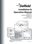
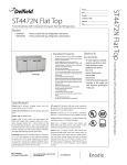
Installation &
Operation Manual
4400 Series
Compact Refrigerators
4500 Series
Compact Freezers
Please read this manual
completely before
attempting to install or
operate this equipment!
Notify carrier of damage.
Inspect all components
immediately.
Delfield 980 S. Isabella Rd., Mt. Pleasant, MI 48858
(989) 773-7891 or (800) 733-8829 • Fax (989) 773-3210
www.delfield.com
May 2011
Delfield
Contents
Introduction....................................................................................2
Receiving And Inspecting The Equipment.......................................2
Specifications...............................................................................3-8
Installation.................................................................................9-10
Location..................................................................................9
Inside Cabinet.........................................................................9
Outside Cabinet.......................................................................9
Leveling..................................................................................9
Stabilizing...............................................................................9
Plumbing................................................................................9
Electrical Connection...............................................................9
Cutting Board Bracket Mounting...........................................10
Shelf Installation Instructions...............................................10
2-Position Pan Rails Installation Instructions.......................10
Operation.................................................................................11-12
Refrigeration Temperature Control........................................11
Freezer Temperature Control.................................................12
Maintenance.............................................................................13-14
Stainless Care And Cleaning.................................................13
Condenser Coil Cleaning.......................................................13
Gasket...................................................................................13
Doors/hinges........................................................................14
Drain.....................................................................................14
Drawer Maintenance.............................................................14
Introduction
All cabinets have stainless steel exteriors and ABS interiors.
Door gaskets are magnetic and mount to the door, snapping
in place and are removable without tools.
Serial Number Location
The serial tag is located either on the left upper sidewall
inside the cabinet or under the top nosing directly above
the door when the door is in the closed position (right hand
door when there are two doors).
Always have the serial number of your cabinet available
when calling for parts or service. A complete list of
authorized Delfield parts depots is available on our website
at www.delfield.com.
This manual covers standard cabinets only. If you have a
custom cabinet, consult the customer service department
at (800) 733-8829.
©2011 The Delfield Company. All rights reserved. Reproduction without written
permission is prohibited. “Delfield” is a registered trademark of The Delfield Company.
Wiring Diagram........................................................................15-16
Standard Labor Guidelines............................................................17
Limited Lifetime Warranty.............................................................18
Standard One Year Warranty.........................................................19
Receiving And Inspecting The Equipment
Even though most equipment is shipped crated, care should be
taken during unloading so the equipment is not damaged while
being moved into the building.
1. Visually inspect the exterior of the package an skid or
container. Any damage should be noted and reported to the
delivering carrier immediately.
2. If damaged, open and inspect the contents with the carrier.
3. In the event that the exterior is not damaged, yet upon
opening, there is concealed damage to the equipment notify
the carrier. Notification should be made verbally as well as
in written form.
4. Request an inspection of the concealed equipment. This
should be done within 10 days from receipt of the equipment.
5. Check the lower portion of the unit to be sure legs or casters
are not bent.
2
6. Also open the compressor compartment housing and
visually inspect the refrigeration package. Be sure lines are
secure and base is still intact.
7. Freight carriers can supply the necessary forms upon
request.
8. Retain all crating material until an inspection has been made
or waived.
9. Do not use forklift or pallet jack to move this equipment
once it is removed from the pallet. Doing so may cause
equipment damage and void warranty.
Uncrating the Equipment
First cut and remove the banding from around the crate. Remove
the front of the crate material, use of some tools will be required.
If the unit is on legs remove the top of the crate as well and lift
the unit off the skid. If the unit is on casters it can be "rolled" off
the skid.
Compact Refrigerators
Specifications
Undercounter Refrigerators
Model
Description
L
D
Work H
Volume
Shelves
1/6 Pan
FT3
FT2
Capacity
H.P.
Refg. Charge
Amp
(oz)
NEMA
Ship Weight
Plug
(lbs)
UC4427N
one door
27”
31.5”
34.25”
8.20
3.17
—
1/5
7.0
3.9
5-15P
223
UCD4427N
two drawer
27”
31.5”
34.25”
8.20
—
—
1/5
7.0
3.9
5-15P
245
UC4432N
one door
32”
31.5”
34.25”
10.10
3.88
—
1/5
7.0
3.9
5-15P
245
UCD4432N
two drawer
32”
31.5”
34.25”
10.10
—
—
1/5
7.0
3.9
5-15P
293
UC4448N
two door
48”
31.5”
34.25”
16.00
5.48
—
1/5
7.0
3.9
5-15P
316
UCD4448N
four drawer
48”
31.5”
34.25”
16.00
—
—
1/5
7.0
3.9
5-15P
398
UC4460N
two door
60”
31.5”
34.25”
20.20
7.19
—
1/5
7.0
3.9
5-15P
411
UCD4460N
four drawer
60”
31.5”
34.25”
20.20
—
—
1/5
7.0
3.9
5-15P
495
UC4464N
two door
64”
31.5”
34.25”
21.60
7.76
—
1/5
7.0
3.9
5-15P
421
UCD4464N
four drawer
64”
31.5”
34.25”
21.60
—
—
1/5
7.0
3.9
5-15P
522
UC4472N
three door
72”
31.5”
34.25”
24.80
8.22
—
1/5
7.0
3.9
5-15P
461
UCD4472N
six drawer
72”
31.5”
34.25”
24.80
—
—
1/5
7.0
3.9
5-15P
545
Volume
Shelves
1/6 Pan
H.P.
FT3
FT2
Capacity
Flat Top & Work Top Refrigerator Bases
Model
Description
L
D
Work H
Refg.
Amp
Charge (oz)
NEMA
Ship Weight
Plug
(lbs)
4427N
one door
27”
31.5”
36”
8.20
3.17
—
1/5
7.0
3.9
5-15P
223
D4427N
two drawer
27”
31.5”
36”
8.20
—
—
1/5
7.0
3.9
5-15P
245
ST4427N
one door
27”
31.5”
36”
8.20
3.17
—
1/5
7.0
3.9
5-15P
223
STD4427N
two drawer
27”
31.5”
36”
8.20
—
—
1/5
7.0
3.9
5-15P
245
4432N
one door
32”
31.5”
36”
10.10
3.88
—
1/5
7.0
3.9
5-15P
245
D4432N
two drawer
32”
31.5”
36”
10.10
—
—
1/5
7.0
3.9
5-15P
293
ST4432N
one door
32”
31.5”
36”
10.10
3.88
—
1/5
7.0
3.9
5-15P
245
STD4432N
two drawer
32”
31.5”
36”
10.10
—
—
1/5
7.0
3.9
5-15P
293
4448N
two door
48”
31.5”
36”
16.00
5.48
—
1/5
7.0
3.9
5-15P
316
D4448N
four drawer
48”
31.5”
36”
16.00
—
—
1/5
7.0
3.9
5-15P
398
ST4448N
two door
48”
31.5”
36”
16.00
5.48
—
1/5
7.0
3.9
5-15P
316
STD4448N
four drawer
48”
31.5”
36”
16.00
—
—
1/5
7.0
3.9
5-15P
398
4460N
two door
60”
31.5”
36”
20.20
7.19
—
1/5
7.0
3.9
5-15P
411
D4460N
four drawer
60”
31.5”
36”
20.20
—
—
1/5
7.0
3.9
5-15P
495
ST4460N
two door
60”
31.5”
36”
20.20
7.19
—
1/5
7.0
3.9
5-15P
411
STD4460N
four drawer
60”
31.5”
36”
20.20
—
—
1/5
7.0
3.9
5-15P
495
4464N
two door
64”
31.5”
36”
21.60
7.76
—
1/5
7.0
3.9
5-15P
421
D4464N
four drawer
64”
31.5”
36”
21.60
—
—
1/5
7.0
3.9
5-15P
522
ST4464N
two door
64”
31.5”
36”
21.60
7.76
—
1/5
7.0
3.9
5-15P
421
STD4464N
four drawer
64”
31.5”
36”
21.60
—
—
1/5
7.0
3.9
5-15P
522
4472N
three door
72”
31.5”
36”
24.80
8.22
—
1/5
7.0
3.9
5-15P
461
D4472N
six drawer
72”
31.5”
36”
24.80
—
—
1/5
7.0
3.9
5-15P
545
ST4472N
three door
72”
31.5”
36”
24.80
8.22
—
1/5
7.0
3.9
5-15P
461
STD4472N
six drawer
72”
31.5”
36”
24.80
—
—
1/5
7.0
3.9
5-15P
545
ST prefix models have a 4" stainless steel backsplash.
3
Delfield
Specifications, continued
Salad Top Refrigerator Bases
Model
Description
L
D
Work H
Volume FT3 Shelves
1/6 Pan
FT2
Capacity
H.P.
Refg. Charge
Amp
(oz)
NEMA
Ship Weight
Plug
(lbs)
4427N-6
one door
27”
31.5”
36”
8.20
3.17
6
1/5
9
7.2
5-15P
223
D4427N-6
two drawer
27”
31.5”
36”
8.20
—
6
1/5
9
7.2
5-15P
245
4448N-8
two door
48”
31.5”
36”
16.00
5.48
8
1/5
9
7.2
5-15P
316
D4448N-8
four drawer
48”
31.5”
36”
16.00
—
8
1/5
9
7.2
5-15P
398
4448N-12
two door
48”
31.5”
36”
16.00
5.48
12
1/5
9
7.2
5-15P
316
D4448N-12
four drawers
48”
31.5”
36”
16.00
—
12
1/5
9
7.2
5-15P
398
ST4448N-8
two door
48”
31.5”
36”
16.00
5.48
8
1/5
9
7.2
5-15P
316
STD4448N-8
four drawers
48”
31.5”
36”
16.00
—
8
1/5
9
7.2
5-15P
398
4460N-8
two door
60”
31.5”
36”
20.20
7.19
8
1/2
12
12
5-15P
411
D4460N-8
four drawer
60”
31.5”
36”
20.20
—
8
1/2
12
12
5-15P
495
4460N-12
two door
60”
31.5”
36”
20.20
7.19
12
1/2
12
12
5-15P
411
D4460N-12
four drawer
60”
31.5”
36”
20.20
—
12
1/2
12
12
5-15P
495
ST4460N-8
two door
60”
31.5”
36”
20.20
7.19
8
1/2
12
12
5-15P
411
STD4460N-8
four drawer
60”
31.5”
36”
20.20
—
8
1/2
12
12
5-15P
495
4464N-8
two door
64”
31.5”
36”
21.60
7.76
8
1/2
12
12
5-15P
421
D4464N-8
four drawer
64”
31.5”
36”
21.60
—
8
1/2
12
12
5-15P
522
4464N-12
two door
64”
31.5”
36”
21.60
7.76
12
1/2
12
12
5-15P
421
D4464N-12
four drawer
64”
31.5”
36”
21.60
—
12
1/2
12
12
5-15P
522
4464N-16
two door
64”
31.5”
36”
21.60
7.76
16
1/2
12
12
5-15P
421
D4464N-16
four drawer
64”
31.5”
36”
21.60
—
16
1/2
12
12
5-15P
522
ST4464N-8
two door
64”
31.5”
36”
21.60
7.76
8
1/2
12
12
5-15P
421
STD4464N-8
four drawer
64”
31.5”
36”
21.60
—
8
1/2
12
12
5-15P
522
ST4464N-12
two door
64”
31.5”
36”
21.60
7.76
12
1/2
12
12
5-15P
421
STD4464N-12
four drawer
64”
31.5”
36”
21.60
—
12
1/2
12
12
5-15P
522
4472N-12
three door
72”
31.5”
36”
24.80
8.22
12
1/2
12
12
5-15P
461
D4472N-12
six drawer
72”
31.5”
36”
24.80
—
12
1/2
12
12
5-15P
545
4472N-18
three door
72”
31.5”
36”
24.80
8.22
18
1/2
12
12
5-15P
461
D4472N-18
six drawer
72”
31.5”
36”
24.80
—
18
1/2
12
12
5-15P
545
ST4472N-12
three door
72”
31.5”
36”
24.80
8.22
12
1/2
12
12
5-15P
461
STD4472N-12
six drawer
72”
31.5”
36”
24.80
—
12
1/2
12
12
5-15P
545
ST prefix models have a 4" stainless steel backsplash.
4
Compact Refrigerators
Specifications, continued
Mega Top Refrigerated Front Breathers
Model
Description
L
D
Work H
Volume
Shelves
1/6 Pan
FT3
FT2
Capacity
H.P.
Refg. Charge
Amp
(oz)
NEMA
Ship Weight
Plug
(lbs)
4427N-9M
one door
27”
31.5”
36”
8.20
3.17
9
1/5
9
7.2
5-15P
223
D4427N-9M
two drawer
27”
31.5”
36”
8.20
—
9
1/5
9
7.2
5-15P
245
4427N-12M
one door
27”
31.5”
36”
8.20
3.17
12
1/5
9
7.2
5-15P
223
D4427N-12M
two drawer
27”
31.5”
36”
8.20
—
12
1/5
9
7.2
5-15P
245
ST4427N-12M
one door
27”
31.5”
36”
8.20
3.17
12
1/5
9
7.2
5-15P
223
STD4427N-12M
two drawer
27”
31.5”
36”
8.20
—
12
1/5
9
7.2
5-15P
245
4432N-12M
one door
32”
31.5”
36”
10.10
3.88
12
1/5
9
7.2
5-15P
245
D4432N-12M
two drawer
32”
31.5”
36”
10.10
—
12
1/5
9
7.2
5-15P
293
4448N-18M
two door
48”
31.5”
36”
16.00
5.48
18
1/5
9
7.2
5-15P
316
D4448N-18M
four drawer
48”
31.5”
36”
16.00
—
18
1/5
9
7.2
5-15P
398
4460N-12M
two door
60”
31.5”
36”
20.20
7.19
12
1/2
12
12
5-15P
411
D4460N-12M
four drawer
60”
31.5”
36”
20.20
—
12
1/2
12
12
5-15P
495
4460N-18M
two door
60”
31.5”
36”
20.20
7.19
18
1/2
12
12
5-15P
411
D4460N-18M
four drawer
60”
31.5”
36”
20.20
—
18
1/2
12
12
5-15P
495
4460N-24M
two door
60”
31.5”
36”
20.20
7.19
24
1/2
12
12
5-15P
411
D4460N-24M
four drawer
60”
31.5”
36”
20.20
—
24
1/2
12
12
5-15P
495
ST4460N-12M
two door
60”
31.5”
36”
20.20
7.19
12
1/2
12
12
5-15P
411
STD4460N-12M
four drawer
60”
31.5”
36”
20.20
—
12
1/2
12
12
5-15P
495
ST4460N-18M
two door
60”
31.5”
36”
20.20
7.19
18
1/2
12
12
5-15P
411
STD4460N-18M
four drawer
60”
31.5”
36”
20.20
—
18
1/2
12
12
5-15P
495
4464N-12M
two door
64”
31.5”
36”
21.60
7.76
12
1/2
12
12
5-15P
421
D4464N-12M
four drawer
64”
31.5”
36”
21.60
—
12
1/2
12
12
5-15P
522
4464N-18M
two door
64”
31.5”
36”
21.60
7.76
18
1/2
12
12
5-15P
421
D4464N-18M
four drawer
64”
31.5”
36”
21.60
—
18
1/2
12
12
5-15P
522
4464N-24M
two door
64”
31.5”
36”
21.60
7.76
24
1/2
12
12
5-15P
421
D4464N-24M
four drawer
64”
31.5”
36”
21.60
—
24
1/2
12
12
5-15P
522
ST4464N-12M
two door
64”
31.5”
36”
21.60
7.76
12
1/2
12
12
5-15P
421
STD4464N-12M
four drawer
64”
31.5”
36”
21.60
—
12
1/2
12
12
5-15P
522
ST4464N-18M
two door
64”
31.5”
36”
21.60
7.76
18
1/2
12
12
5-15P
421
STD4464N-18M
four drawer
64”
31.5”
36”
21.60
—
18
1/2
12
12
5-15P
522
4472N-18M
three door
72”
31.5”
36”
24.80
8.22
18
1/2
12
12
5-15P
461
D4472N-18M
six drawer
72”
31.5”
36”
24.80
—
18
1/2
12
12
5-15P
545
4472N-24M
three door
72”
31.5”
36”
24.80
8.22
24
1/2
12
12
5-15P
461
D4472N-24M
six drawer
72”
31.5”
36”
24.80
—
24
1/2
12
12
5-15P
545
4472N-30M
three door
72”
31.5”
36”
24.80
8.22
30
1/2
12
12
5-15P
461
D4472N-30M
six drawer
72”
31.5”
36”
24.80
—
30
1/2
12
12
5-15P
545
ST4472N-18M
three door
72”
31.5”
36”
24.80
8.22
18
1/2
12
12
5-15P
461
STD4472N-18M
six drawer
72”
31.5”
36”
24.80
—
18
1/2
12
12
5-15P
545
ST4472N-24M
three door
72”
31.5”
36”
24.80
8.22
24
1/2
12
12
5-15P
461
STD4472N-24M
six drawer
72”
31.5”
36”
24.80
—
24
1/2
12
12
5-15P
545
ST prefix models have a 4" stainless steel backsplash.
5
Delfield
Specifications, continued
Reduced Work Height Salad Top Refrigerated Front Breathers
Model
Description
L
D
Work H
Volume
Shelves
1/6 Pan
FT3
FT2
Capacity
H.P.
Refg. Charge
Amp
(oz)
NEMA
Ship Weight
Plug
(lbs)
UC4427N-6
one door
27”
31.5”
34.25”
8.20
3.17
6
1/5
9
7.2
5-15P
223
UCD4427N-6
two drawer
27”
31.5”
34.25”
8.20
—
6
1/5
9
7.2
5-15P
245
UC4448N-8
two door
48”
31.5”
34.25”
16.00
5.48
8
1/5
9
7.2
5-15P
316
UCD4448N-8
four drawer
48”
31.5”
34.25”
16.00
—
8
1/5
9
7.2
5-15P
398
UC4448N-12
two door
48”
31.5”
34.25”
16.00
5.48
12
1/5
9
7.2
5-15P
316
UCD4448N-12
four drawer
48”
31.5”
34.25”
16.00
—
12
1/5
9
7.2
5-15P
398
UC4460N-8
two door
60”
31.5”
34.25”
20.20
7.19
8
1/2
12
12
5-15P
411
UCD4460N-8
four drawer
60”
31.5”
34.25”
20.20
—
8
1/2
12
12
5-15P
495
UC4460N-12
two door
60”
31.5”
34.25”
20.20
7.19
12
1/2
12
12
5-15P
411
UCD4460N-12
four drawer
60”
31.5”
34.25”
20.20
—
12
1/2
12
12
5-15P
495
UC4464N-8
two door
64”
31.5”
34.25”
21.60
7.76
8
1/2
12
12
5-15P
421
UCD4464N-8
four drawer
64”
31.5”
34.25”
21.60
—
8
1/2
12
12
5-15P
522
UC4464N-12
two door
64”
31.5”
34.25”
21.60
7.76
12
1/2
12
12
5-15P
421
UCD4464N-12
four drawer
64”
31.5”
34.25”
21.60
—
12
1/2
12
12
5-15P
522
UC4464N-16
two door
64”
31.5”
34.25”
21.60
7.76
16
1/2
12
12
5-15P
421
UCD4464N-16
four drawer
64”
31.5”
34.25”
21.60
—
16
1/2
12
12
5-15P
522
UC4472N-12
three door
72”
31.5”
34.25”
24.80
8.22
12
1/2
12
12
5-15P
461
UCD4472N-12
six drawer
72”
31.5”
34.25”
24.80
—
12
1/2
12
12
5-15P
545
UC4472N-18
three door
72”
31.5”
34.25”
24.80
8.22
18
1/2
12
12
5-15P
461
UCD4472N-18
six drawer
72”
31.5”
34.25”
24.80
—
18
1/2
12
12
5-15P
545
6
Compact Refrigerators
Specifications, continued
Reduced Work Height Mega Top Refrigerated Front Breathers
Model
Description
L
D
Work H
Volume
Shelves
1/6 Pan
FT3
FT2
Capacity
H.P.
Refg. Charge
Amp
(oz)
NEMA
Ship Weight
Plug
(lbs)
UC4427N-9M
one door
27”
31.5”
34.25”
8.20
3.17
9
1/5
9
7.2
5-15P
223
UCD4427N-9M
two drawer
27”
31.5”
34.25”
8.20
—
9
1/5
9
7.2
5-15P
245
UC4427N-12M
one door
27”
31.5”
34.25”
8.20
3.17
12
1/5
9
7.2
5-15P
223
UCD4427N-12M
two drawer
27”
31.5”
34.25”
8.20
—
12
1/5
9
7.2
5-15P
245
UC4432N-12M
one door
32”
31.5”
34.25”
10.10
3.88
12
1/5
9
7.2
5-15P
245
UCD4432N-12M
two drawer
32”
31.5”
34.25”
10.10
—
12
1/5
9
7.2
5-15P
293
UC4448N-18M
two door
48”
31.5”
34.25”
16.00
5.48
18
1/5
9
7.2
5-15P
316
UCD4448N-18M
four drawer
48”
31.5”
34.25”
16.00
—
18
1/5
9
7.2
5-15P
398
UC4460N-12M
two door
60”
31.5”
34.25”
20.20
7.19
12
1/2
12
12
5-15P
411
UCD4460N-12M
four drawer
60”
31.5”
34.25”
20.20
—
12
1/2
12
12
5-15P
495
UC4460N-18M
two door
60”
31.5”
34.25”
20.20
7.19
18
1/2
12
12
5-15P
411
UCD4460N-18M
four drawer
60”
31.5”
34.25”
20.20
—
18
1/2
12
12
5-15P
495
UC4460N-24M
two door
60”
31.5”
34.25”
20.20
7.19
24
1/2
12
12
5-15P
411
UCD4460N-24M
four drawer
60”
31.5”
34.25”
20.20
—
24
1/2
12
12
5-15P
495
UC4464N-12M
two door
64”
31.5”
34.25”
21.60
7.76
12
1/2
12
12
5-15P
421
UCD4464N-12M
four drawer
64”
31.5”
34.25”
21.60
—
12
1/2
12
12
5-15P
522
UC4464N-18M
two door
64”
31.5”
34.25”
21.60
7.76
18
1/2
12
12
5-15P
421
UCD4464N-18M
four drawer
64”
31.5”
34.25”
21.60
—
18
1/2
12
12
5-15P
522
UC4464N-24M
two door
64”
31.5”
34.25”
21.60
7.76
24
1/2
12
12
5-15P
421
UCD4464N-24M
four drawer
64”
31.5”
34.25”
21.60
—
24
1/2
12
12
5-15P
522
UC4472N-18M
three door
72”
31.5”
34.25”
24.80
8.22
18
1/2
12
12
5-15P
461
UCD4472N-18M
six drawer
72”
31.5”
34.25”
24.80
—
18
1/2
12
12
5-15P
545
UC4472N-24M
three door
72”
31.5”
34.25”
24.80
8.22
24
1/2
12
12
5-15P
461
UCD4472N-24M
six drawer
72”
31.5”
34.25”
24.80
—
24
1/2
12
12
5-15P
545
UC4472N-30M
three door
72”
31.5”
34.25”
24.80
8.22
30
1/2
12
12
5-15P
461
UCD4472N-30M
six drawer
72”
31.5”
34.25”
24.80
—
30
1/2
12
12
5-15P
545
7
Delfield
Specifications, continued
Freezers
Flat top freezer bases
L
D
Work H
Volume
Ft.3
Shelves
Ft.2
H.P.
Refg. Charge
(oz)
Amp
NEMA
Plug
Ship
Weight
one door
32”
(81.3cm)
31.5”
(80.0cm)
36”
(91.4cm)
8.80
3.88
1/5
9.0
9.5
5-15P
245lbs
(111kg)
D4532N
two drawer
32”
(81.3cm)
31.5”
(80.0cm)
36”
(91.4cm)
8.80
—
1/3
9.0
9.5
5-15P
293lbs
(133kg)
ST4532N
one door
32”
(81.3cm)
31.5”
(80.0cm)
36”
(91.4cm)
8.80
3.88
1/5
9.0
9.5
5-15P
245lbs
(111kg)
STD4532N
two drawer
32”
(81.3cm)
31.5”
(80.0cm)
36”
(91.4cm)
8.80
—
1/3
9.0
9.5
5-15P
293lbs
(133kg)
4560N
two door
60”
(152.4cm)
31.5”
(80.0cm)
36”
(91.4cm)
16.90
7.19
1/3
14.0
12.0
5-15P
411lbs
(186kg)
ST4560N
two door
60”
(152.4cm)
31.5”
(80.0cm)
36”
(91.4cm)
16.90
7.19
1/3
14.0
12.0
5-15P
411lbs
(186kg)
L
D
Work H
Volume
Ft.3
Shelves
Ft.2
H.P.
Refg. Charge
Amp
NEMA
Plug
Ship
Weight
Model
Description
4532N
ST prefix models have a 4" stainless steel backsplash.
Undercounter freezers
Model
Description
UC4532N
one door
32”
(81.3cm)
31.5”
(80.0cm)
34.25”
(87.0cm)
8.80
3.88
1/5
9.0
9.5
5-15P
245lbs
(111kg)
UCD4532N
two drawer
32”
(81.3cm)
31.5”
(80.0cm)
34.25”
(87.0cm)
8.80
—
1/3
9.0
9.5
5-15P
293lbs
(133kg)
UC4560N
two door
60”
(152.4cm)
31.5”
(80.0cm)
34.25”
(87.0cm)
16.90
7.19
1/3
14.0
12.0
5-15P
411lbs
(186kg)
8
Compact Refrigerators
Installation
Location
Plumbing
Cabinets represented in this manual are intended for indoor
use only. Be sure the location chosen has a floor strong enough
to support the total weight of the cabinet and contents.
Reinforce the floor as necessary to provide for maximum
loading.
Self-contained models are standard with a condensate
evaporator. If, for some reason, a cabinet does not have a
condensate evaporator, or the evaporator fails, the cabinets
drain must have an outlet to an appropriate drainage area
or container.
The location should be selected so that power cords can be
connected without any extensions.
For the most efficient operation, be sure to provide good air
circulation inside and outside the cabinet. Avoid hot corners
and locations near stoves and ovens.
Inside Cabinet
Do not pack refrigerator so full that air cannot circulate.
Outside Cabinet
4400 Series equipment door and drawer models
These cabinets have Delfield’s “front-breathing” design. They
may be installed flush against a wall or built into a counter
as required.
The louver at the floor level must be kept completely clear
of any obstructions. Proper operation of these models is
dependent on air being able to flow freely through the front
louver. The louver at the back of the cabinet is not necessary for
proper operation, but any air flow through it is beneficial.
Any restriction of the proper air flow outlined
above, total or partial, will void the warranty on
the cabinet.
Leveling
Moisture collecting from improper drainage can
create a slippery surface on the floor and a hazard
to employees. It is the owner’s responsibility to
provide a container or outlet for drainage.
Electrical Connection
A 6’ (1.8 m) long grounded supply cord and three-pronged
plug are provided with standard cabinets. Simply plug into
a three-pronged wall outlet for proper grounding of the
cabinet to begin operation. Do not use an adapter to connect
to a two-pronged outlet. The three-pronged outlet provides
a ground connection which must be used to prevent a shock
hazard.
The wall outlet must be checked by a qualified
electrician to be sure a proper ground is present
and that the outlet provides the correct voltage
and required amperage to match the rating plate.
Any power cord that is frayed or damaged should
be replaced. When disconnecting the cabinet from
the power source, do not pull on the cord. Firmly
grip the plug and remove from outlet.
The 15-P plug shown below is used on the various 4400
Series models.
A level cabinet will perform better because the drain pan
will drain properly, the drawers or doors will line up with the
frames and the cabinet will not be subject to undue strain.
Never stand on the unit or its drawers! Doing so
may result in bodily injury. They are not designed
to hold the weight of a person and will collapse if
misused in this manner.
Stabilizing
All models are supplied standard on casters for your
convenience, for ease of cleaning underneath and for mobility.
The cabinet must be installed in a stable condition
with the front wheels locked. Locking the front
casters after installation is the owner’s and
operator’s responsibility.
Refer to the amperage data list in SPECIFICATIONS, the serial
tag, your local code or the National Electrical Code to be
sure the cabinet is connected to the proper power source.
A protected circuit of the correct voltage and amperage
must be run for connection of the line cord, or permanent
connection to the cabinet.
The thermostat must be turned to OFF and the
cabinet disconnected from the power source
whenever performing service, maintenance
functions or cleaning the refrigerated area.
9
Delfield
Installation, continued
Cutting Board Bracket Mounting
Shelf Installation Instructions
1. Gather brackets, cutting board and screwdriver.
1. Notice the shelves have four alignment pins on the
underside and a backstop on the top back.
2. Open the door to install the center bracket.
3. Remove four screws from the nosing.
4. Place the bracket and secure with the four removed
screws.
2. Insert the shelves into the cabinet.
• The backstop should be at the top back.
• The alignment pins should be in front and back of
the shelf supports.
5. Remove two screws from one end.
6. Place the bracket and secure with the two removed
screws.
Changing Pan Height
7. Repeat at the other end.
8. Insert the cutting board into the brackets, back first.
Lay it down with the holes over the alignment pins.
If additional pan temperature cooling ability is desired,
especially in higher ambient temperature conditions and/
or if pan covers are open or off for extended time periods
improved cooling of pans can usually be achieved by utilizing
the lower position of the dual level pan guides.
When utilizing the lower position on a model with drawers,
only 4" deep pans can be used in the top. When utilizing the
lower position on a door model, 4" or 6" deep pans may be
used.
1. Remove all pans, pan dividers, front and rear support
bars.
2. Remove the upper side support brackets by pulling them
up and off as shown below.
3. Reinstall all components removed in step one.
Remove upper side
support bracket
Use side support alone
to lower pans 1”
10
Compact Refrigerators
Refrigerated Cabinet Operation
After the cabinet is connected to the power source it will
automatically begin operating. With the covers and doors
closed, the temperature of the cabinet should reach 36°F to
40°F (2°C to 4°C) in about one hour. Temperature on salad
top will maintain 33°F to 41°F (1°C to 4°C) with pans recessed
2.5” (6.5cm) at 86°F ambient room temperature for a period
of four hours, meeting NSF-7 requirements. The temperature
control on a flat top unit other than 4427 models is located
on the back panel inside the refrigerator and can be adjusted
to meet the current conditions. The temperature control on
4427 flat top and all salad top units is located in the rear of
the unit, 14" to 16" above floor in access hole.
three minutes on and three minutes off.
3. During an actual defrost event other than the off-cycle
defrost, compressor stays off but the evaporator fan runs
continuously.
Refrigerated cabinets with two evaporators have counterrotating fans to ensure even airflow throughout the cabinet.
The left evaporator has a CCW motor and a clear fan blade
and right evaporator has a CW motor and a black fan blade.
Temperature Control Instruction for Flat Top Units
except 4427 Models
A thermostat located in the evaporator housing on the interior
rear of the cabinet controls the temperature inside the box. The
factory setting for the control is “4” and maintains about 38°F
(3°C) inside the box. Set toward “1” for higher temperatures
and set to a higher number for lower temperatures.
Temperature Control Knob Access
Salad Top Units and 4427 Flat Top Models
Cabinets with pans should be operated with pans
in place. Operating the cabinet without all pans
in place will lessen efficiency and may damage
the cabinet.
Continuous opening and closing of the door will
hamper the cabinet’s ability to maintain optimum
refrigeration temperature.
Top section is not intended for overnight storage.
Product should be removed from pans. Pans can
remain in cabinet while empty.
Defrosting
Flat Top Units except 4427 Models
Temperature Control Instruction for Salad Top
Units and 4427 Flat Top Models
A thermostat located in rear of cabinet controls the
temperature inside the box. The factory setting for the control
is 4.5 and maintains about 34°F(1°C) to 36°F (2°C) inside the
box. Set toward 1 for higher temperatures and set to a higher
number for lower temperatures.
Refrigerators defrost automatically with every cycle of the
compressor. The water generated is routed to a pan on the
rear of the cabinet and is evaporated by the heat given off
by the compressor.
Service Alert
During normal operation the evaporator fan may cycle
and/or pulse independently of the compressor. Consult
the service manual or contact Technical Support at
1-800-733-8829 if you are unsure of the proper function.
Cooling Cycle
Compressor On
Important Information on 4427 Solid Top Models:
The unit is Energy Star Version II compliant. During normal
operation the evaporator fan pulses independently of the
compressor as dictated by the Danfoss Controller as follows:
1. During the cooling mode, compressor and evaporator
fan run simultaneously.
2. During the compressor off mode, evaporator fan pulses
Compressor Off
Defrost Cycle
Compressor Off
Evap
Evap
Evap
Evap
Evap
Evap
Fan On Fan Off Fan On Fan Off Fan On Fan Off
4400
Open Top
X
X
X
4400
Solid Top
X
X
X
4427
Solid Top
X
Cycles On 3-Min,
Off 3-Min
X
11
Delfield
Freezer Cabinet Operation
The electronic temperature control constantly monitors
box temperature as well as evaporator coil temperature to
maintain consistent product temperatures.
At initial start-up or anytime power is disconnected, then
reconnected to the unit, the control will delay all operations
for a short time (up to 10 minutes.) While in this delay period,
the control initializes the control parameters and confirms
that the temperature sensors and circuits are operational.
REGARDING FREEZERS: After initializing, the
control will immediately enter a DEFROST mode.
The compressor and condenser fan as well as the
evaporator fan will remain off until initialization
defrost is complete. This initial defrost cycle may
take up to 15 minutes to complete, at which time
the freezing cycle will begin.
Freezer Automatic Defrost
The control also monitors compressor total running time
and will enter a defrost cycle after total compressor running
time is greater than 4-hours since the last defrost cycle OR
if evaporator coil temperature drops below -34ºF (-37ºC)
(indicating excessive frost on the coil.)
When the control enters the defrost mode, it switches off the
evaporator fan motor, compressor and condenser fan motor,
and switches on the defrost heater to warm the evaporator
coil. Thereby melting all frost accumulated during the previous
refrigeration cycle. The control will continue the defrost
cycle for a MINIMUM of 8 minutes and a MAXIMUM of 30
minutes depending on the amount of frost accumulated on
the evaporator coil.
After the defrost cycle is complete, the control returns to a
normal refrigeration cycle, however the evaporator fan motor
will not switch on for 2 minutes AFTER the compressor and
condenser fan motor have begun operating.
Freezer Manual Defrost
If a manual defrost is desired, simply unplug the unit for several
seconds, then plug unit back in. This will cause the control
to re-initialize and then enter a defrost cycle.
Temperature Control Knob Access
Freezers
The control is located in the rear of the cabinet. Freezers
are factory set at mid-range to maintain about -3ºF
(-19ºC) box temperature. To adjust for colder temperatures,
turn the knob clockwise. For warmer temperatures, turn
the knob counter-clockwise. Turn the knob fully counterclockwise to turn the refrigeration system off. Never turn
the knob more than 1 dial number and always allow 8 hours
for temperature stabilization before making any additional
adjustments.
Freezer cabinets with two evaporators have counter-rotating
fans to ensure even airflow throughout the cabinet. The left
evaporator has a CCW motor and a clear fan blade and the
right evaporator has a CW motor and a black fan blade.
The evaporator fan(s) and condenser fan will cycle off and on
with the compressor to conserve energy.
Freezer:
Whenever the freezer is plugged in, and the control has
completed initializing including the initial defrost cycle.
The temperature control will cycle the compressor and
condenser fan motor and evaporator fan motor to maintain
box temperature at the control setting.
12
Service Alert
During normal operation the evaporator fan may cycle
and/or pulse independently of the compressor. Consult
the service manual or contact Technical Support at
1-800-733-8829 if you are unsure of the proper function.
Cooling Cycle
Compressor On
Defrost Cycle
Compressor Off
Compressor Off
Evap
Evap
Evap
Evap
Evap
Evap
Fan On Fan Off Fan On Fan Off Fan On Fan Off
4500
Freezer
X
X
X
Compact Refrigerators
Maintenance
The thermostat must be turned to OFF and the
cabinet disconnected from the power source
whenever performing service, maintenance
functions or cleaning the refrigerated area.
Stainless Steel Care And Cleaning
To prevent discoloration or rust on stainless steel several
important steps need to be taken. First, the properties of
stainless steel need to be understood. Stainless steel contains
70-80% iron which will rust. It also contains 12-30% chromium
which forms an invisible passive film over the steels surface
which acts as a shield against corrosion. As long as the
protective layer is intact, the metal will not corrode and is
still stainless. If the film is broken or contaminated, outside
elements can begin to breakdown the steel and begin to
form rust or other discoloration.
NEVER USE STEEL PADS, WIRE BRUSHES OR
SCRAPERS!
Do not use an abrasive cleaner because it will scratch the
stainless steel and plastic and can damage gaskets. Proper
cleaning of stainless steel requires soft cloths or plastic
scouring pads.
Cleaning solutions need to be alkaline based or non-chloride
cleaners. Any cleaner containing chlorides will damage
the protective film of the stainless steel. Chlorides are also
commonly found in hard water, salts and household and
industrial cleaners. If cleaners containing chlorides are
used, be sure to rinse repeatedly and dry thoroughly upon
completion.
Routine cleaning of the interior and exterior can be done
with soap and warm water. Extreme stains or grease should
be cleaned with a non-abrasive cleaner and plastic scrub
pad. When cleaning the exterior, always rub with the grain
of the stainless steel to avoid marring the finish. There are
also stainless steel cleaners available which can restore and
preserve the finish of the steels protective layer.
Early signs of stainless steel breakdown can consist of small
pits and cracks. If this has begun, clean thoroughly and start
to apply stainless steel cleaners in an attempt to restore the
passivity of the steel.
Never use an acid based cleaning solution! Many
food products have an acidic content which
can deteriorate the finish. Be sure to clean ALL
food products from any stainless steel surface.
Common items include, tomatoes, peppers and
other vegetables.
CLEANING THE CONDENSER COIL
The condenser coil requires regular cleaning every 90 days
(recommended). In some instances you may find a large
amount of debris and dust or grease accumulated prior to the
90 day time frame. In these cases the condenser coil should
be cleaned every 30 days.
If the build up on the coil consists of only light dust and debris
the condenser coil can be cleaned with a simple brush. Heavier
dust build up may require a vacuum or even compressed air
to blow through the condenser coil.
If heavy grease is present there are de-greasing agents available
for refrigeration use, and specifically for the condenser coils.
The condenser coil may require using a de-greasing agent
and then being blown through with compressed air. Follow
the de-greasing agent manufacturer’s instructions.
Failure to maintain a clean condenser coil can initially cause
high temperatures and excessive run times. Continuous
operation with dirty or clogged condenser coils can result in
compressor failure. Neglecting the condenser coil cleaning
procedures will void any warranties associated with the
compressor or cost to replace the compressor.
Never use a high pressure water wash for this
cleaning procedure as water can damage the
electrical components located near or at the
condenser coil.
In order to maintain proper refrigeration performance, the
condenser fins must be cleaned of dust, dirt and grease
regularly. It is recommended that this be done every three
months. If conditions are such that the condenser is totally
blocked in three months, the frequency of cleaning should be
increased. Clean the condenser with a vacuum cleaner or stiff
brush. If extremely dirty, a commercially available condenser
cleaner may be required.
If your freezer seems to vibrate excessively when the
compressor is running, loosen (but do not remove) the bolts
on the compressor. Semi-hermetic models should be loosened
before operating.
Gasket Maintenance
Gaskets require regular cleaning to prevent mold and mildew
build up and also to maintain the elasticity of the gasket. Gasket
cleaning can be done with the use of warm soapy water. Avoid
full strength cleaning products on gaskets as this can cause
them to become brittle and prevent proper seals. Also, never
use sharp tools or knives to scrape or clean the gasket which
could possibly tear the gasket and rip the bellows.
Gaskets can easily be replaced and do not require the use of
tools or authorized service persons. The gaskets are “Dart”
13
Delfield
Maintenance, continued
style and can be pulled out of the groove in the door and
new gaskets can be “pressed” back into place.
clean the track on the bottom of the drawer box. When finished,
it should be wiped clean of all food and debris.
Doors/Hinges
Tracks
Over time and with heavy use the door hinges may become
loose. If it is noticed that the door is beginning to sag, it may
be necessary to tighten the screws that mount the hinge
brackets to the frame of the cabinet. If the doors are loose
or sagging, this can cause the hinge to pull out of the frame
which may damage both the doors and the door hinges.
In some cases this may require repair by a qualified service
agent or maintenance personnel.
The drawer box assembly must be removed. Pull the drawer
tracks out until they hit a stop. Locate blue safety clips towards
the back of each drawer track. Blue safety clips have a tab on the
top. Push the tab back until it clicks. Lift up and pull the drawer
tracks all the way out of the
drawer cage. The drawer
tracks are dishwasher
safe or can be cleaned
tab on top of
in a sink with detergents
blue safety clip and a soft bristle brush.
Drawers and tracks should
be cleaned on a weekly basis. Using a soft bristle brush, wash the
track making sure each roller is thoroughly cleaned. The drawer
cage should be cleaned with a soft bristle brush, removing any
food and debris gathered on the bottom ledge. Once it’s cleaned
thoroughly with a soft bristle brush, wipe remaining debris clean
with a soft towel.
Reassembly
Drain Maintenance
Each cabinet has a drain located inside which removes the
condensation from the evaporator coil and evaporates it
at an external condensate evaporator pan. Each drain can
become loose or disconnected from moving or bumping
the drain. If you notice excessive water accumulation on the
inside of the cabinet, be sure the drain tube is connected from
the evaporator housing to the condensate evaporator drain
pan. If water has collected underneath the cabinet, check the
condensate evaporator drain tube to be sure it is still located
inside the drain pan. Leveling the cabinet is important as it
is designed to drain properly when on a level surface. If your
floor is not level this can also cause drain problems. Be sure
all drain lines are free of obstructions. Typically, food product
is found blocking drain lines causing water to back up and
overflow the drain pans.
Drawer Maintenance
Drawer Assembly Cleaning
The drawer assembly is designed to be cleaned easily. Both drawer
and tracks are removable without tools. The drawer tracks are
dishwasher safe or can be cleaned in a sink with detergents and
a soft bristle brush. Drawers and tracks should be cleaned on a
weekly basis.
Remove Drawers
Pull the drawer box out until it stops. Lift up on the drawer front
and pull the drawer box completely out. Using a soft bristle brush,
14
Push the drawer tracks into the drawer cage. The blue safety
clip must remain pushed towards the back. Lift up and slide the
drawer track all the way into the drawer cage. The blue safety clip
will lock in place automatically. Once all tracks are replaced, insert
the drawer box. Rest the drawer box bottom track on the front
track roller. Then push the drawer back in place SLOWLY. When the
drawer box is about half way in you will hit a STOP. You must lift
the front of the drawer up approximately ½” (1.3cm) to continue
inward. Clean tracks as often as possible. The cleaner the tracks
are the better they will operate.
Compact Refrigerators
Wiring Diagram, 4427 Flat Top Refrigerator
9294473
9294473
Wiring Diagram, All Remaining Flat Top Refrigerators
L1
BLACK
G
N
NEMA 5-15P
Supply Cord and
Plug furnished
WHITE
EVAPORATOR FAN
HPS
TEMPERATURE
CONTROL
CONDENSING UNIT
15
CONDENSING UNIT
Delfield
Wiring Diagram, Salad & Mega Top Refrigerators
NEMA 5-15P
Supply Cord and
Plug furnished
L1
Temperature Control
Knob Access
EVAPORATOR FANS
TEMPERATURE
CONTROL
1 3
5
HPS
Wiring Diagram, Freezers
DUAL EVAPORATOR
UNITS ONLY
MULLION
HEATER
16
CONDENSING
UNIT
N
Compact Refrigerators
Standard Labor Guidelines To Repair Or Replace Parts On Delfield Equipment
Advice and recommendations given by Delfield Service Technicians do not constitute or guarantee any special coverage.
A maximum of 1-hour is allowed to diagnose a defective component.
A maximum of 1-hour is allowed for retrieval of parts not in stock.
A maximum travel distance of 100 miles round trip and 2-hours will be reimbursed.
Overtime, installation/start-up, normal control adjustments, general maintenance, glass breakage, freight damage, and/or correcting and end-user installation error will not be reimbursed under warranty unless pre-approved with a Service Work Authorization
from Delfield. You must submit the number with the service claim.
LABOR OF 1-HOUR IS ALLOWED TO REPLACE:
• Thermostat
• Evaporator/Condenser Fan Motor and Blade
• Hi-limit/Thermal Protector Switch
• Door Hinges, Locks, and Gaskets
• Compressor Start Components and Overload Protector
LABOR OF 2 HOURS IS ALLOWED TO REPLACE:
• Drawer Tracks/Cartridges
• Locate/Repair a Leak
• Defrost Heater
LABOR OF 3 HOURS IS ALLOWED TO REPLACE:
• Condenser or Evaporator Coil
• Hot gas condensate evaporator
LABOR OF 4 HOURS IS ALLOWED TO REPLACE
Compressor
This includes recovery of refrigerant and leak check.
$55.00 maximum reimbursement for refrigerant recovery (includes recovery machine, pump, torch, oil, flux, minor fittings, solder,
brazing rod, nitrogen, or similar fees.)
REFRIGERANTS
R404A A maximum of $15.00/lb. or $1.00/oz. will be reimbursed.
17
Delfield
Manufacturers Limited Lifetime Warranty
Delfield warrants to the original purchaser-user, subject to the
limitations and exclusions set forth below, that the ABS interior of
the Delfield models identified above will be free of manufactured
defects for as long as the equipment is owned by the original
purchaser-user and is in operation.
What is covered
For purposes of this Warranty, interior liner is defined as the
portion of the interior liner which is made of ABS material. This
Warranty applies only to products sold and installed after March
1, 2000 in the United States, Canada, Puerto Rico, and Mexico.
For purposes of this Warranty, lifetime is defined as the expected
usable life for the equipment of 12 years.
Delfield’s Obligation
Limited strictly to shipping OEM replacement parts or repair kits
for any ABS covered interior. A Delfield authorized service dealer
and Delfield’s Service Department must confirm the liner defect
has occurred under normal conditions and is not due to misuse
as defined below. All decisions regarding the ABS interior shall
be made by Delfield’s Service Department and shall be binding
upon the parties. No labor or service charges or allowances are
covered by this warranty. Warranty service must be performed
by a Delfield approved authorized service agent.
User Responsibility
The product must be installed, cleaned and maintained as described in the Installation & Operation manual which is furnished
with the product. Only approved replacement parts may be used.
Failure to adhere to the requirements of this paragraph may void
warranty coverage.
Procedures
All claims for replacement parts or repair kits must be made
through a Delfield Parts Depot or an authorized Delfield dealer.
The defective part invoice must be returned to Delfield within 15
days after the date of service to be eligible for warranty coverage.
All claims must include the model, serial number, an original date
of installation and customer identification. Use of parts other than
original Delfield replacement parts will not be covered.
18
Exclusions
This warranty does not cover labor, service, charges for travel
time, mileage, or premium charges. This warranty also does not
include defects resulting from:
Operation of the product beyond the specification set forth in
the Service and Installation Manual.
Failure to clean and maintain the product as described in the
Service and Installation Manual.
Installation of the product in a manner other than as set forth in
the Service and Installation.
Use or installation of replacement parts not approved by Delfield:
or The introduction of hot items directly onto the ABS liner.
This warranty is in lieu of all other warranties or guarantees of
any kind, express or implied, except Delfield’s One Year Parts
and 90-Day Warranty 4400 Series. ANY IMPLIED WARRANTIES OR MERCHANTABILITY OR FITNESS FOR A PARTICULAR
PURPOSE ARE HEREBY DISCLAIMED AND EXCLUDED. IN NO
EVENT SHALL DELFIELD BE LIABLE FOR INCIDENTAL OR CONSEQUENTIAL DAMAGES OF ANY KIND OR NATURE, OR FOR ANY
DEFECT RESULTING IN WHOLE OR IN PART FROM MISUSE,
ALTERATION, IMPROPER INSTALLATION OR INADEQUATE
MAINTENANCE OF THE PRODUCT OR ANY PART THEREOF.
No part or assembly which has been subject to accident, alteration or misuse, or which has not been installed or serviced in
accordance with the Installation & Operation Manual furnished
with the product, or which is from equipment on which the serial number has been altered or removed, shall be covered by
this warranty.
Compact Refrigerators
Standard One Year Warranty (One Year Parts, 90 Days Labor)
The Delfield Company (“Delfield”) warrants to the Original Purchaser of
the Delfield product (herein called the “Unit”) that such Unit, and all parts
thereof, will be free from defects in material and workmanship under normal
use and service for a period of one (1) year from the date of shipment of
the Unit to the Original Purchaser or, if the Original Purchaser returns
the warranty card completely filled out including the date of installation
within thirty (30) days of receipt of the Unit, one (1) year from the date
of installation. During this one year warranty period, Delfield will repair
or replace any defective part or portion there of returned to Delfield by the
Original Purchaser which Delfield determines was defective due to faulty
material or workmanship. The Original purchaser will pay all labor, crating,
freight and related costs incurred in the removal of the Unit or defective
component and shipment to Delfield, except that during a period of either
ninety (90) days from the date of shipment of the Unit to the Original
Purchaser or, if the Original Purchaser returns the warranty card completely
filled out including the date of installation within thirty (30) days of receipt
of the Unit, ninety (90) days from the date of installation Delfield will pay
all related labor costs. Delfield will pay the return costs if the Unit or part
thereof was defective.
The term “Original Purchaser” as used herein means that person, firm,
association, or corporation for whom the Unit was originally installed.
This warranty does not apply to any Unit or part thereof that has been
subjected to misuse, neglect, alteration, or accident, such as accidental
damage to the exterior finish, operated contrary to the recommendations
specified by Delfield; or repaired or altered by anyone other than Delfield in
any way so as to, in Delfield’s sole judgement, affect its quality or efficiency.
This warranty does not apply to any Unit that has been moved from the
location where it was originally installed. This warranty also does not cover
the refrigerator drier or the light bulbs used in the Unit. The warranty is
subject to the user’s normal maintenance and care responsibility as
set forth in the Service and Installation Manual, such as cleaning the
condenser coil, and is in lieu of all other obligations of Delfield. Delfield
neither assumes, nor authorizes any other person to assume for Delfield,
any other liability in connection with Delfield’s products.
Removal or defacement of the original Serial Number or Model Number from
any Unit shall be deemed to release Delfield from all obligations hereunder
or any other obligations, express or implied.
Parts furnished by suppliers to Delfield are guaranteed by Delfield only to
the extent of the original manufacturer’s express warranty to Delfield. Failure
of the Original Purchaser to receive such manufacturers warranty shall in
no way create any warranty, expressed or implied, or any other obligation
or liability on Delfield’s part in respect thereof.
IF THE CUSTOMER IS USING A PART THAT RESULTS IN A VOIDED
WARRANTY AND A DELFIELD AUTHORIZED REPRESENTATIVE TRAVELS
TO THE INSTALLATION ADDRESS TO PERFORM WARRANTY SERVICE, THE
SERVICE REPRESENTATIVE WILL ADVISE CUSTOMER THE WARRANTY
IS VOID. SUCH SERVICE CALLS WILL BE BILLED TO CUSTOMER AT
THE AUTHORIZED SERVICE CENTER’S THEN APPLICABLE TIME AND
MATERIALS RATES. CONSIDER: CUSTOMER MAY INITIATE A SERVICE
AGREEMENT WITHOUT PARTS COVERAGE.
No claims can be made under this warranty for spoilage of any products
for any reason, including system failure.
The installation contractor shall be responsible for building access, entrance
and field conditions to insure sufficient clearance to allow any hood(s),
vent(s), or Unit(s) if necessary, to be brought into the building. Delfield
will not be responsible for structural changes or damages incurred during
installation of the Unit or any exhaust system.
Delfield shall not be liable in any manner for any default or delay in performance
hereunder caused by or resulting from any contingency beyond Delfield’s
control, including, but not limited to, war, governmental restrictions or
restraints, strike, lockouts, injunctions, fire, flood, acts of nature, short
or reduced supply of raw materials, or discontinuance of the parts by the
original part manufacturer.
Except as provided in any Additional Four Year Protection Plan, if
applicable, and the Service Labor Contract, if applicable, the foregoing
is exclusive and in lieu of all other warranties, whether written or oral,
express or implied. This warranty supersedes and excludes any prior oral
or written representations or warranties. Delfield expressly disclaims any
implied warranties of merchantability, fitness for a particular purpose, or
compliance with any law, treaty, rule or regulation relating to the discharge
of substances into the environment. The sole and exclusive remedies of
any person relating to the Unit, and the full liability of Delfield for any
breach of this warranty, will be as provided in this warranty.
Other than this Delfield Standard One Year Limited Warranty, any applicable
Delfield Additional Four Year Protection Plan or applicable Delfield Service
Labor Contract, the Original Purchaser agrees and acknowledges that no
other warranties are offered or provided in connection with or for the Unit
or any other part thereof.
In no event will Delfield be liable for special, incidental or consequential
damages, or for damages in the nature of penalties.
IF DURING THE WARRANTY PERIOD, CUSTOMER USES A PART FOR
THIS DELFIELD EQUIPMENT OTHER THAN AN UNMODIFIED NEW OR
RECYCLED PART PURCHASED DIRECTLY FROM DELFIELD OR ANY OF
ITS AUTHORIZED SERVICE CENTERS AND/OR THE PART BEING USED
IS MODIFIED FROM ITS ORIGINAL CONFIGURATION, THIS WARRANTY
WILL BE VOID. FURTHER, DELFIELD AND ITS AFFILIATES WILL NOT BE
LIABLE FOR ANY CLAIMS DAMAGES OR EXPENSES INCURRED BY THE
CUSTOMER WHICH ARISE DIRECTLY OR INDIRECTLY, IN WHOLE OR IN
PART, DUE TO THE INSTALLATION OF ANY MODIFIED PART AND/OR PART
RECEIVED FROM AN UNAUTHORIZED SERVICE CENTER. If the warranty
becomes void, Customer may purchase from Delfield, if available, a
Service Agreement or service at the then current time and materials rate.
For more information on Delfield warranty’s log on and check out the service
section of our web site at www.delfield.com.
If shipment of a replacement part is requested prior to the arrival in the
Delfield factory of the part claimed to be defective, the Original Purchaser
must accept delivery of the replacement part on a C.O.D. basis, with credit
being issued after the part has been received and inspected at Delfield’s
plant and determined by Delfield to be within this warranty.
Under no condition does this warranty give the Original Purchaser the right
to replace the defective Unit with a complete Unit of the same manufacturer
or of another make. Unless authorized by Delfield in writing, this warranty
does not permit the replacement of any part, including the motor-compressor,
to be made with the part of another make or manufacturer.
19
Covington, TN
Mt. Pleasant, MI
Thank you for choosing Delfield!
Help is a phone call away. Help our team of professional, courteous customer
service reps by having your model number and serial number available at the time
of your call (800) 733-8829.
Model:________________________ S/N: _______________________
Installation Date:________________
For a list of Delfield’s authorized parts depots,
visit our website at www.delfield.com.
Delfield
™
®
980 S. Isabella Rd., Mt. Pleasant, MI 48858, U.S.A. • (989) 773-7981 or (800) 733-8829 • Fax (989) 773-3210 • www.delfield.com
Delfield reserves the right to make changes in design or specifications without prior notice. ©2011 The Delfield Company. All rights reserved. Printed in the U.S.A.
DM44_4500 05/11
9294098