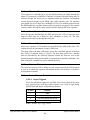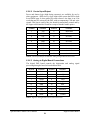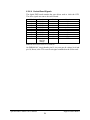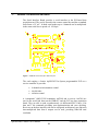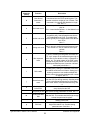
1
PixelVision, Inc.
Rev: C
PMD-004-00012-00
SPECTRAVIDEO™ CAMERA USER’S MANUAL
DOCUMENT CHANGE NOTICE
REV
DATE
DCN
ORIGINATOR
SUMMARY OF CHANGES
A
2/8/98
n/a
T. Nebeker
Original Document
B
4/15/99
n/a
T. Nebeker
Updates/Edits
C
2/15/00
n/a
T. Nebeker
Updates/Edits
™
SPECTRAVIDEO CAMERA
USER’S M ANUAL
LIMITED WARRANTY
™
PixelVision of Oregon, Inc. warrants that The SpectraVideo series of cameras
(the “camera”) will perform essentially in accordance with the accompanying
documentation for a period of one (1) year from date of receipt. If there are
physical defects in workmanship or materials in the camera or documentation that
are not associated with normal use and service, PixelVision, Inc. will replace or
repair camera or documentation free of charge within the period of one (1) year
from the date of receipt. The limited warranty is void if failure of the camera has
resulted from accident, abuse or misapplication on the part of the user.
If the camera must be returned to PixelVision, Inc. for replacement or
repair, it must be packed in its original material, as it was shipped to you.
The limited warranty may be voided if the camera is not returned in its
original packing material.
Some states do not allow exclusions or limitations of implied warranties, so the
above limitations or exclusions may not apply to you. This warranty gives you
specific legal rights and you may also have other rights that vary from state to
state.
DAMAGE DISCLAIMER
At no time will PixelVision, Inc. be liable for direct, indirect, incidental or
consequential damage to hardware or software, loss of business profits, loss of
clients (potential and existing) or loss of information arising from the use or
™
™
inability to use the SpectraVideo series cameras, PixelView software program
or pertaining documentation. PixelVision, Inc. has no liability for any data stored
or processed with this software, including any costs for recovery of such data.
Copyright © 1998 PixelVision of Oregon, Inc. All Rights Reserved
PMD-004-00012-00 Rev. C
Table of Contents
1. INTRODUCTION............................................................................................ 1
2. GENERAL DESCRIPTION OF CAMERA............................................................ 2
2.1.
2.2.
2.3.
2.4.
DIGITAL DATA ACQUISITION BOARD .................................................................... 3
PIXELVIEW SOFTWARE....................................................................................... 3
SOFTWARE DEVELOPER’S KIT ............................................................................ 3
SYSTEM REQUIREMENTS .................................................................................... 3
3. SPECTRAVIDEO CAMERA SETUP ................................................................. 5
3.1.
3.2.
3.3.
PRECAUTIONS ................................................................................................... 5
SETUP .............................................................................................................. 5
SPECTRAVIDEO FAMILY GENERAL SPECIFICATIONS ............................................. 9
4. CAMERA EXPOSURE CONTROL .................................................................. 10
4.1.
4.2.
EXTERNAL EXPOSURE CONTROL ...................................................................... 10
SOFTWARE TRIGGERED EXPOSURE CONTROL ................................................... 11
5. ANALOG SIGNAL PROCESSING BOARD ...................................................... 12
5.1.
5.2.
OVERVIEW....................................................................................................... 12
ANALOG SIGNAL PROCESSING BOARD CONNECTIONS........................................ 12
5.2.1.
5.2.2.
5.2.3.
5.2.4.
5.2.5.
GAIN SELECTION ......................................................................................................... 12
ANALOG OUTPUT ........................................................................................................ 13
BOARD TO BOARD SIGNAL CONNECTIONS ..................................................................... 14
DIGITAL INPUT/OUTPUT ................................................................................................ 15
RS232 INPUT .............................................................................................................. 15
6. DIGITAL CONTROL BOARD ........................................................................ 17
6.1.
6.2.
OVERVIEW....................................................................................................... 17
TIMING SEQUENCE ........................................................................................... 17
6.2.1.
6.2.2.
6.2.3.
6.2.4.
6.2.5.
6.2.6.
6.2.6.1.
6.2.6.2.
6.2.6.3.
6.2.6.4.
FLUSH MODE .............................................................................................................. 18
EXPOSURE MODE ........................................................................................................ 19
AFTER EXPOSURE MODE.............................................................................................. 19
READOUT MODE .......................................................................................................... 19
CLOCKING PARAMETERS.............................................................................................. 19
DIGITAL CONTROL BOARD CONNECTIONS ...................................................................... 19
Scope Triggers ............................................................................................................................................... 19
Control Input/Output ..................................................................................................................................... 20
Analog to Digital Board Connections ......................................................................................................... 20
Socket Board Signals.................................................................................................................................... 21
7. SERIAL INTERFACE BOARD ....................................................................... 22
8. SHUTTER AND COOLING CONTROL BOARD ................................................. 24
9. DATA ACQUISITION BOARDS ..................................................................... 25
9.1.
LYNXPCI DATA ACQUISITION BOARD ................................................................ 25
SpectraVideo Camera User’s Manual
Table of Contents
9.1.1.
9.1.2.
9.1.3.
9.1.4.
10.
11.
FEATURES .................................................................................................................. 25
GENERAL DESCRIPTION ............................................................................................... 25
ARCHITECTURE ........................................................................................................... 26
GENERAL SPECIFICATIONS ........................................................................................... 27
BOARD TO BOARD ELECTRICAL CONNECTIONS ..................................... 28
SOFTWARE DEVELOPMENT ................................................................... 29
11.1. SPECTRAVIDEO SERIAL PORT INTERFACE ......................................................... 29
11.1.1.
11.1.2.
11.1.3.
12.
REBOOT COMMANDS ................................................................................................... 30
REGION OF INTEREST (ROI) IMPLEMENTATION................................................................ 30
COMMAND SUMMARY ................................................................................................... 31
SUPPORTING SOFTWARE ...................................................................... 34
™
12.1. COMMTEST SOFTWARE USER’S GUIDE ........................................................... 34
™
12.2. PIXLOAD SERIAL PORT CONTROL SOFTWARE ................................................. 35
12.2.1.
12.2.2.
13.
TEXT FILE FORMAT ...................................................................................................... 35
SAMPLE TEXT FILE ...................................................................................................... 36
APPENDICES ........................................................................................ 38
13.1. APPENDIX A .................................................................................................... 38
13.1.1.
HEAD ASSEMBLY MECHANICAL DRAWING ...................................................................... 38
13.2. APPENDIX B .................................................................................................... 39
13.2.1.
CAMERA CONTROL BOX MECHANICAL DRAWING ............................................................ 39
13.3. APPENDIX C .................................................................................................... 40
13.3.1.
13.3.2.
SPECTRAVIDEO 1 CAMERA LOW LEVEL COMMAND SUMMARY ......................................... 40
DSP CONTROL OUTPUTS ............................................................................................. 43
GLOSSARY OF ACRONYMS AND TERMS ........................................................... 44
INDEX OF CONTENTS...................................................................................... 46
SpectraVideo Camera User’s Manual
Table of Contents
1.
INTRODUCTION
The SpectraVideo™ series of high performance, charge-coupled device (CCD)
cameras, manufactured by PixelVision, Inc., offer excellent sensitivity and low
noise throughout the visible and ultra-violet spectral regions. The affordable
SpectraVideo series cameras use Scientific Imaging Technologies, Inc. (SITe)designed CCDs. The camera’s back-illuminated CCD detector has as high as
ninety-nine percent quantum efficiency in the visible spectral region.
An optional ultra-violet, anti-reflective coating allows for excellent sensitivity
throughout the visible and ultra-violet spectral regions.
Thinned, back-illuminated CCDs overcome the performance limits of the
conventional front-illuminated CCDs by illuminating and collecting charge
through the back surface away from the polysilicon gate electrodes on the front
surface. The image photons enter the CCD back surface unobstructed, allowing
for high quantum efficiency visible and ultra-violet light detection. Software gain
and shutter control allow variable exposure, binning, region of interest (ROI) and
timing.
The camera is delivered with a head assembly, camera control box, data
™
acquisition board and PixelView (PixelVision, Inc.’s easy-to-use Microsoft
®
Windows -based software package). The head assembly and camera control box
provide all of the necessary circuitry to operate the CCD array and provide low
™
noise signals to the computer interface. A LynxPCI data acquisition board
acquires the images. The detector head is adaptable to most popular lens mounts,
with an ‘F’ mount standard. Exposure, temperature, gain and pixel binning are
controlled using PixelView.
SpectraVideo Camera User’s Manual
Introduction
1
2.
GENERAL DESCRIPTION OF CAMERA
The SpectraVideo series camera is a two-piece camera design. A schematic
representation of the camera is shown in Figure 1 The CCD, thermoelectric
cooler, and pre-amplifier are all contained in the head assembly. The amplified
output of the CCD is transmitted over coaxial cable to the SpectraVideo camera
control box.
CCD Analog
Signal Cable
00 00 00 00 00 00 00 00 00 00 00 00 00 00 00 00 00 00
00 00 00 00 00 00Head
00 00 00 00 00 00 00 00 00 00 00 00
0 0 0 0Assembly
00000000000000
00 00 00 00 00 00 00 00 00 00 00 00 00 00 00 00 00 00
Data Cable
Drive Cable
Serial Cable
00 00 00 00 00 00 00 00 00 00 00 00 00 00 00 00 00 00 00 00 00 00 00
00 00 00 00 00 00 00 00Camera
00 00 00 00 00 00 00 00 00 00 00 00 00 00 00
0 0 0 0 0 Control
0 0 0 0 0 0 0 0 0 Box
000000000
00000000000000000000000
00000000000000000000000000000
00 00 00 00 00 00 00 00 00 00 00 00 00 00 00 00 00 00 00 00 00 00 00 00 00 00 00 00 00
PixelView™
0 0 0 0 0 0 0 0Software
0 0 0 0 0 0 0 0 0 0 0for0 0 0 0 0 0 0 0 0 0
00 00 00 00 00 00 00 00 00 Windows
00 00 00 00 00 00 00 00 00 00 00 00 00 00 00 00 00 00 00 00
00 00 00 00 00 00 00 00 00 00 00 00 00 00 00 00 00 00 00 00 00 00 00 00 00 00 00 00 00
00 00 00 00 00 00 00 00 00 00 00 00 00 00 00 00 00 00 00 00 00 00 00 00 00 00 00 00 00 00 00 00
00 00 00 00 00 00 00 00 00 00 00 00 00 00 00 00 00User
00 00 00 00 00 00 00 00 00 00 00 00 00 00 00
0 0 0 0 0 0 0 0 0 0 0 0 supplied
0 0 0 0 0 0 0 0 0 0 0PC0 0 0 0 0 0 0 0 0
3.1x, 95/98 or NT
Data
Acquisition
Board
Figure 1 Schematic Representation of the SpectraVideo camera electronics
The CCD clock and bias signals are provided to the head from the camera control
box through the drive cable. The pre-amplified CCD signal is returned through
the CCD analog signal cable. The camera control box houses: 1) the power
supplies necessary to operate the camera and thermoelectric cooler; 2) the digital
control board that generates the clocking to operate the CCD; 3) the analog signal
processing board; and 4) the shutter and cooler control board. On those cameras
using a PCI bus data acquisition card and fiber optic data link, a serial to parallel
converter board is also contained in the camera control box.
The digital control board contains the sequencer which generates the logic signals
for all time critical tasks associated with the CCD readout, the drivers which clock
the CCD gates, and the bias supplies for the driver rails. The sequencer is a
programmable digital signal processor (DSP) and many timing parameters are
controlled through its serial port. The analog signal processing board contains the
correlated double sampled (CDS) analog signal chain, the 16 bit, analog-to-digital
converter (ADC) and optical isolation from the PC to improve noise immunity.
SpectraVideo Camera User’s Manual
General Description of Camera
2
2.1. DIGITAL DATA ACQUISITION BOARD
SpectraVideo cameras are shipped with a 16 bit digital input interface to a
LynxPCI data acquisition board that acquires the images. The data acquisition
board receives digital signals from the SpectraVideo camera and the PixelView
software program captures the data that corresponds to the image’s pixel intensity
values and places the image into the PC memory, pixel-by-pixel. For more
detailed information on the data acquisition board, see Section 1.
2.2. PIXELVIEW SOFTWARE
PixelView software is provided with every SpectraVideo camera. PixelView is an
easy-to-use Windows-based image acquisition and analysis software package that
supports the features of the SpectraVideo camera. The software also includes
many intuitive image processing and analysis tools. Through the data acquisition
board, PixelView captures the 16 bit data that corresponds to the image’s pixel
intensity values and places the image into the PC memory, pixel-by-pixel.
PixelView has an intuitive structure where images and graphics are associated
with windows. The Shortcut Key feature (a combination of mouse drags and key
pushes) makes graphics and analysis just a touch away. Some of the most
commonly used analysis and display tools are accessible from toolbox buttons.
The pull down menu system is user friendly and easy to learn.
For detailed information on the functions of the PixelView software program,
please refer to the PixelView Software User’s Manual.
2.3. SOFTWARE DEVELOPER’S KIT
PixelView uses device drivers that are loaded at system boot. These drivers can
also be accessed from the user’s software through provided DLLs.
2.4. SYSTEM REQUIREMENTS
The recommended hardware system to run your SpectraVideo camera is a 233
MHz Pentium processor with at least 64 MB of RAM and 5 MB of available disk
space.
PixelView is compatible with Windows 95/98/NT. It is not compatible with
earlier versions of Window. The program also requires a display adapter that
supports at least 256-color displays.
PixelView supports 1-, 2-, or 4-channel versions of the LynxPCI data acquisition
board with either a parallel or fiber optic interface. In addition, PixelView
supports controlling a single camera using two LynxPCI cards, but does not
support controlling multiple cameras with multiple boards.
SpectraVideo Camera User’s Manual
General Description of Camera
3
The camera determines the data acquisition rate and you must ensure that your
computer has sufficient resources to keep up with the rate at which the camera
transmits data. Computers operating with higher clock speeds will not acquire
images faster than the rate determined by the camera; however, as bus and
microprocessor clock speeds improve the efficiency in which the computer
handles background tasks, a faster computer increases the reliability of acquiring
images.
PixelView does not interface directly with any other program; however, the
software reads and writes files that can be shared with other programs. PixelView
uses TIFF as its default file format.
SpectraVideo Camera User’s Manual
General Description of Camera
4
3.
SPECTRAVIDEO CAMERA SETUP
3.1. PRECAUTIONS
CAUTION! Charge-Coupled Devices (CCDs) are extremely sensitive to
electrostatic discharge (ESD) damage. The CCD may be damaged by
discharges of as low as 50 Volts. Do not unplug the head assembly unless at an
ESD safe workstation.
Your camera may have been shipped with the Head Assembly separate from the
camera control box. If so, the Head Assembly will have a shorting bar on its 37pin connector. Do not remove the shorting bar unless at an ESD safe workstation.
Connect the Head Cable to the camera control box. Remove the shorting bar and
replace it with the Head Cable. Be sure the Head Cable connectors are screwed in
at both ends.
The computer +5 Volt supply is available on pin 37 of the D37 connector of
parallel data acquisition board. It is highly recommended that the computer be
turned off when connecting the data cable on these cameras. The PCI data
acquisition board has a fuse on this supply voltage pin. A damaged fuse on a PCI
board can cause a serial port command upload failure error message.
Please save all packing material! If the camera must be returned to
PixelVision, Inc. for replacement or repair, it must be packed in its original
material, as it was shipped to you. The limited warranty may be voided if the
camera is not returned in its original packing material. If you need new
packing material, please contact PixelVision, Inc.
3.2. SETUP
Your SpectraVideo camera is shipped prepared for easy integration and operation.
Included in your shipment is a Packing List. Please verify that all parts have been
received. If any parts listed in the Packing List are not received with this package,
please contact PixelVision, Inc. Immediately.
Start by plugging the power cord into the power supply box then into a grounded
power source (a grounded wall socket is preferred). Leave the camera and
computer off until all the cabling is connected.
CAUTION! The camera is shipped with the drive cable from the camera control
box to the head assembly connected. DO NOT REMOVE THIS CABLE.
Removal will expose the static-sensitive CCD to possible electrostatic discharge
(ESD) damage.
SpectraVideo Camera User’s Manual
SpectraVideo Camera Setup
5
For the camera control box to communicate with your PC, the data acquisition
board must be installed, if there is not one already installed. To install the board:
1. Make sure the computer is turned off.
2. Leave your computer plugged into a grounded power source, if it is
not already plugged in (a grounded wall socket is preferred).
3. Remove the computer’s chassis cover and locate a free PCI expansion
slot.
4. Remove the protective plate covering that corresponds to the chassis
slot, saving the machine screw.
5. Dissipate any static electricity by touching a bare-metal portion of the
PC chassis.
6. Remove the data acquisition card from the anti-static bag, holding the
board’s edge (do not touch the board’s back or the connectors
because these areas are more susceptible to retained static charge).
7. Insert data acquisition board into the free PCI expansion slot, making
sure that the board is fully seated.
8. Secure the board bracket using the machine screw from the chassis slot
plate.
9. Replace the chassis cover.
If you are not using a PCI bus data acquisition board with fiber optic links, you
must connect the 9-pin serial data cable from the port on the back of the camera
control box marked “serial control” to a free serial (COM) port on your PC. Note
which serial (COM) port you are using for setup of PixelView. Then connect the
parallel cable from the port marked “Parallel Data” to the parallel port on the data
acquisition card. Figure 2 shows the camera setup with serial/parallel cabling. If
you are using a fiber optic link, install the fiber optic cables from the data
acquisition board to the camera control box.
CAUTION! When inserting or detaching the fiber optic cables, grasp the
metal nut at the end of the cable. Do not push or pull on the cable itself.
When removing the plastic cover at the tip of the cable, grasp the metal nut,
not the cable. DO NOT tie the fiber optic cable in a knot. Bending the cable
in a circle with a radius smaller than four inches can damage the cable.
To connect the fiber optic cables:
1. Remove the fiber optic port plugs by turning counter-clockwise ¼ turn and
then pulling out.
2. The first fiber optic cable goes from the port labeled “FO1” on the back of the
camera control box to the top fiber optic port on the data acquisition board.
The “top” port is the port farthest away from where the board is plugged into
the extension slot. Remember to loosen or tighten the cable using the metal
nut. Do not push or pull the cable itself. Rotate the metal nut clockwise until
the key slot drops into place.
SpectraVideo Camera User’s Manual
SpectraVideo Camera Setup
6
3. The next cable goes from the port labeled “FO2” on the back of camera
control box to the next available port on the data acquisition board (again, in
order from top to bottom on the board).
☞
NOTE: If the camera control box has more than two fiber optic ports, continue to
use the next available port on the data acquisition board for each cable coming
from the camera control box, in order from top to bottom on the board.
Once the cables are connected, restart your computer. If you are running
PixelView and a LynxPCI data acquisition board, when you restart your
computer, Windows 95 should inform you that it has detected new hardware, and
ask you for a driver disk for this hardware. Insert the disk label “PCI Driver Disk”
into your 3½" floppy drive, select that drive, and click “OK.” Follow any
instructions Windows 95 presents. Some PC systems may prompt you for a file
name or directory in the Copy files from: box. If this occurs, type the correct path
to your floppy drive (i.e. ‘a:’) and press enter. You may have to direct the search
to your floppy drive more than once on some systems, especially if your system
has a CD-ROM drive.
For “internal exposure” use the short coaxial “exposure control loop back” cable
provided to connect the “Exposure Out” connector on the back of the camera
control box to the “Exposure In” connector (see Figure 2). For external exposure,
disconnect this cable and provide a TTL gate to the “Exposure In” connector (see
Section 4.1 for detailed information). In internal exposure, the camera controls the
exposure start and exposure duration; but, while in external exposure mode,
exposure is slaved to the gate pulse provided by the user.
SpectraVideo Camera User’s Manual
SpectraVideo Camera Setup
7
Figure 2 SpectraVideo Camera with Serial/Parallel Cable Interface
The camera head is provided with a Nikon lens mount standard. A C-mount or
Canon lens mount is optional. A ¼ inch – 20 tpi mounting hole is provided in the
camera head.
For specific information on the installation of the PixelView software program,
please refer to the PixelView Software User’s Manual.
SpectraVideo Camera User’s Manual
SpectraVideo Camera Setup
8
3.3. SPECTRAVIDEO FAMILY GENERAL SPECIFICATIONS
Below are the general specifications for the SpectraVideo family.
–
Full Well Capacity
80,000 – 1,200,000 e
Readout Amplifier Noise
4 - 9 e–/per readout @ -45°C., 50kpix/sec
A/D Conversion
16 bit
Readout Rate
50 - 450 kpix/sec (1 Mpix/sec optional)
Shutter
DC to 50 milliseconds, software or external sync control
Row Shift Period
24 – 60 µsec
Gain Settings
Software select, High (app. 4.5 e–/ADU) or Low (app. 9 e–/ADU)
Binning and Region-of-Interest (ROI) Binning and ROI is software selectable in X and Y coordinates
2-stage TE Vacuum Module -45 – -60°C from ambient
Cooling Capacity
3-stage TE O-ring Dewar -70°C from ambient
Electrical Input
100 VAC - 240 VAC 50 - 60Hz
Computer Interface
Serial port and PCI bus (fiber optic cabling available with PCI
bus)
Camera Head Dimensions
4.0"(w) x 4.0"(h)
Operating Mode
Software selectable via serial port or fiber optic link
Recommended Computer System
Requirements
233MHz Pentium processor with at least 64 MB of RAM and
5MB of available disk space
Software
PixelView is provided with each camera
Table 1 SpectraVideo Family General Specifications
SpectraVideo Camera User’s Manual
SpectraVideo Camera Setup
9
4.
CAMERA EXPOSURE CONTROL
4.1. EXTERNAL EXPOSURE CONTROL
Exposure may be controlled externally by supplying a TTL level to the “Exposure
In” connector on the back of the camera control box, with “Exposure Out”
disconnected. The TTL level is normally high; exposure will occur while the level
is pulled low. With a brief delay (typically 15 µs), as soon as the level goes low,
the camera will go into exposure mode and communication with the camera will
be suspended until exposure is discontinued and a frame readout is complete.
If you are running PixelView, exposure must be set to Externally Gated in the
Exposure Tab within the “Camera Setup” dialog box under the Control menu.
A new frame must then be acquired. The software will wait until an exposure has
occurred and will capture the frame. Pressing the Escape key will cancel the
acquisition. Once a single frame has been acquired, selecting the Continuous
(Ctrl-C) item from the Acquire menu makes continuous acquisitions.
The entrance into exposure mode may be delayed for as long as it takes the
parallel gate drivers to fall, typically 15 µs. Consequently, the exposure gate
should precede the external event by at least 15 µs.
After the exposure gate rises, the CCD will continue to expose to allow time for a
shutter to close, phosphor to decay, etc. The length of time is determined by the
value entered in the “After Exposure” box within the Rate Tab of the “Camera
Setup” dialog box under the Control menu. After exposure wait can also be
accessed by the user’s software. Figure 3 below shows the relationships between
the various waveforms.
Figure 3 Exposure Timing Relationships
SpectraVideo Camera User’s Manual
Camera Exposure Control
10
When using an external exposure gate, the beginning of exposure will not be
synchronized with the end of a CCD line and there will be a slight difference in
dark current between two frames with the same exposure. This results from the
dark current accumulated during the uncertainty in one line. This effect should be
small for cooled CCDs running at high speeds.
When externally gated exposure mode is selected, the Digital Signal Processor
(DSP) stops the parallel gates for the duration of the low level on the exposure
gate (± ½ row readout + one parallel shift).
☞
NOTE: When using a PCI data acquisition board, the 100 µs signal is the signal
that is generated by the PCI board. The signal goes to the DSP that controls CCD
shifting. This DSP acts on the falling edge.
4.2. SOFTWARE TRIGGERED EXPOSURE CONTROL
To use software triggered exposure control, the connector on the camera control
box labeled “Exposure Out” must be looped back to the connector labeled
“Exposure In.” A short coaxial cable is provided with each camera for this use. If
PixelView used, exposure must be set to Software Trigger in the Exposure Tab
within the “Camera Setup” dialog box under the Control menu.
Internal exposure timing is handled by the DSP and when a new frame is
requested, the camera will complete clearing the serial register before beginning
the exposure. A TTL level that is low while the camera is exposing is available at
the Sync connector on the front panel of the camera control box.
Internal exposure duration may be set from 25 µs to over 100 hours with a
granularity of 100 ns or 62.5 ns, depending on the frequency of the system clock.
When externally triggered exposure mode is selected, the DSP stops the CCD
parallel gates for the programmed exposure time, starting on the falling edge of
the Exposure In signal.
SpectraVideo Camera User’s Manual
Camera Exposure Control
11
5.
ANALOG SIGNAL PROCESSING BOARD
5.1. OVERVIEW
The analog signal processing board is used to amplify the output signal from the
CCD and digitize it. The analog processing board contains the clamp/sample
correlated double sample circuit, the analog signal chain, the analog-to-digital
converter, and the optical isolation circuitry that provides noise immunity from
the PC.
Figure 4 SpectraVideo Analog Processing Board Layout
One of two gain settings can be selected on the analog signal processing board. A
buffered analog output is also available for troubleshooting and for external signal
processing.
5.2. ANALOG SIGNAL PROCESSING BOARD CONNECTIONS
5.2.1.
GAIN SELECTION
Two analog gain settings, HIGH and LOW, are used to set the gain of the analog
channel on the analog signal processing board.
Unless otherwise specified by the customer, the HIGH gain setting is used to
adjust the dynamic range of the analog-to-digital converter (ADC) so that the
SpectraVideo Camera User’s Manual
Analog Signal Processing Board
12
upper end of the dynamic range is set to the full well potential of the CCD’s
parallel pixel charge sites and so that 2 bits are used to sample the noise floor of
the camera. The LOW gain setting is used to match the upper end of the ADC’s
dynamic range to the full well potential of the CCD’s serial pixels. Under typical
operating conditions, gain setting is performed by the PixelView software
package.
☞
NOTE: If you are running a two-speed camera, the HIGH gain setting is used for
high speed operation, and the LOW gain is used for low speed operation.
5.2.2.
ANALOG OUTPUT
Buffered analog output (0 to -10V range) taken just prior to input to the analog to
digital converter is available on J7 outer most pin. DC offset may be adjusted on
R11 of the clamp sample piggyback board.
J7 pin 2
J7 pin 2
Analog output
GND
Table 2 Analog Output on the PMB-003
J5 pin
Function
J5 pin
Function
1
-15V
2
Last Gate
3
GND
4
Vrd
5
GND
6
Vdd
7
+15V
8
GND
9
GND
10
Analog Signal
Table 3 Low Noise Cable Connection to Socket Board
SpectraVideo Camera User’s Manual
Analog Signal Processing Board
13
5.2.3.
BOARD TO BOARD SIGNAL CONNECTIONS
Control signals from the DSP digital board control. Analog signal processing for
noise reduction and data conversion.
J1 pin
Function
J1 pin
Function
1
-15Vdc
2
~Sample/Hold 1
3
GND
4
~Start Convert
5
+5Vdc
6
~Output Enable
7
+15Vdc
8
~Sample/Hold2
9
GND
10
Expo_Gate
11
GND
12
Gain
13
GND
14
Serdatain
15
GND
16
Serdataout
17
GND
18
Frame blank
19
serclk
20
Line blank
Table 4 Analog Board to Digital Board Control Cable Connections
SpectraVideo Camera User’s Manual
Analog Signal Processing Board
14
5.2.4.
DIGITAL INPUT/OUTPUT
J3 pin
Function
J3 pin
Function (with Serial I/O)
1
Data 0 (LSB)
2
n/c
3
Data 1
4
n/c
5
Data 2
6
PC GND
7
Data 3
8
Line Blanking pulse
9
GND
10
Frame Blanking pulse
11
Data 4
12
~ Output enable 0
13
Data 5
14
PC GND
15
Data 6
16
~ Output enable 1
17
Data 7
18
n/c
19
GND
20
Data Valid strobe
21
Data 8
22
~ Output enable 2
23
Data 9
24
PC GND
25
Data 10
26
~ Output enable 3
27
Data 11
28
n/c
29
GND
30
n/c
31
Data 12
32
n/c
33
Data 13
34
n/c
35
Data 14
36
+5V from PC
37
Data 15
(MSB)
38
TTL in
39
Serial clock
40
TTL out
Table 5 PMB-003 Data I/O Connector
5.2.5.
RS232 INPUT
RS232 control of DSP parameters is accessible through the RS232 connector.
This connector can be connected straight across to a DB9 connector. These
RS232 connections also appear in the data I/O connector (J3) for convenience.
Parallel SpectraVideo cameras use an RS232 port. CommTest is a program used
to exercise the serial port of the Imaging Module in order to determine the health
of the link. For more information on the CommTest program see Section 12.1.
SpectraVideo Camera User’s Manual
Analog Signal Processing Board
15
J4 pin
Function
J4 pin
Function
1
NC
2
nc
3
RS232 input
4
nc
5
RS232 output
6
nc
7
NC
8
nc
9
GND
10
nc
Table 6 PMB-003 RS232 Connector
SpectraVideo Camera User’s Manual
Analog Signal Processing Board
16
6.
DIGITAL CONTROL BOARD
6.1. OVERVIEW
The SpectraVideo digital control board generates the clock signals used to operate
the CCD. High performance clock drivers generate the clock signals. A digital
signal processor (DSP) controls the clock waveforms. Using a DSP allows users
flexibility in operating and optimizing the CCD. Readout rates, pixel binning, and
region of interest readout are all easily modified using the DSP.
J2
J3
Figure 5 SpectraVideo Digital Control Board Layout
6.2. TIMING SEQUENCE
The DSP program has four basic modes: flush, exposure, after exposure and
readout. During the flush mode the CCD is cleared as quickly as possible and the
data is not transferred to the PC. Exposure mode is entered from the flush mode.
During the exposure interval the CCD central array is not shifted to avoid blurring
of the image. An after exposure delay can be set through the serial port to allow
time for the shutter to close or a phosphor to decay before readout. The readout
mode is entered from the after exposure mode. During readout the charge in the
CCD pixels is clocked out, amplified, processed and digitized. A Data Valid
strobe is active for those pixels that will be transferred to the computer. If region
of interest readout is active, only the data from the region will have Data Valid
strobes.
SpectraVideo Camera User’s Manual
Digital Control Board
17
An Exposure Gate pulse of 25 µs minimum width must be provided to this board
to trigger exposure as discussed below.
A Line Blank and Frame Blank pulse are provided in addition to the Data Valid
strobe. The Line Blanking pulse is high for the parallel shifts. Line Blanking is
only active with a Region of Interest (ROI) selected. Frame Blanking is low
during the exposure period, high during the after exposure delay and then low
during the readout. In this way the I/O channel to the PC can sense the internal
exposure gate timing.
EG=Exposure Gate
DV=Data Valid
LB=Line Blanking
FB=Frame Blanking
Figure 6 Camera Control Timing for Internal Exposure Mode
☞
NOTE: For external exposure mode, EG must be high the entire exposure period.
Parallel mode is used with the parallel data input option and serial mode is used
with the serial fiber optic input option.
6.2.1.
FLUSH MODE
After readout or after rebooting the DSP, the CCD is kept flushed of charge
indefinitely by a parallel transfer, serial readout sequence. The only way to get out
of this mode is to trigger an exposure.
SpectraVideo Camera User’s Manual
Digital Control Board
18
6.2.2.
EXPOSURE MODE
CCD exposure is controlled by a user provided external gate (input through the
digital I/O connector on PMB-003). Internal or External exposure timing may be
selected through the serial port as explained under the software development
section. Exposure begins on the falling edge of the exposure gate. The exposure
gate should stay low or high for a minimum of 25µs. For internal exposure mode
the DSP handles the exposure duration after an exposure is triggered. For external
exposure mode, the exposure gate must be held low through the entire exposure.
6.2.3.
AFTER EXPOSURE MODE
After the exposure has finished, the DSP will keep the CCD in exposure mode
longer to allow time for a shutter to close, phosphor to decay, etc. The after
exposure wait can be set through the serial port.
6.2.4.
READOUT MODE
After every exposure, a CCD readout occurs with the data valid strobe active. The
readout may not be interrupted, except by DSP reset.
The rising edge of the data valid strobe occurs after valid data appears on the data
bus. There is a pipeline delay of 3 pixels. The first three pixels after a parallel
shift are discarded by the warm-up sequence because the first two were in the
pipeline during the shift plus the third is slewing back to baseline conditions. The
data valid pulse is blanked except for unblanked pixels.
6.2.5.
CLOCKING PARAMETERS
The serial port may be used to change several counters used in the DSP program
as well as to control the exposure and readout modes. See Section 1 on software
development for details.
6.2.6.
DIGITAL CONTROL BOARD CONNECTIONS
6.2.6.1. Scope Triggers
Pixel, line and frame triggers are available. Pixel clock is high for the reset
gate period of the serial pixel shift sequence, line clock is high during
parallel shift and shutter is high during exposure.
J1 pin #
Function
1
GND
2
Pixel clock (reset gate logic)
3
Line clock (parallel shift period)
4
Shutter
Table 7 PMB-001 Scope Trigger Outputs
SpectraVideo Camera User’s Manual
Digital Control Board
19
6.2.6.2. Control Input/Output
Power and shutter logic (high during exposure) are available for use by
other equipment. ~DSP reset is a logic input which causes the DSP to boot
from PROM page 0 when pulled low and released. Aux data is an 8 bit
word that may be written by the DSP with accompanying CLK and write
signals. This port is used by the Aux board for temperature control and by
the Jaguar serial interface board for receipt of channel enable pulses.
J2 Pin #
Function
J2 Pin #
Function
1
-15V
2
~DSP reset
3
GND
4
Shutter
5
+5V
6
Aux dat 1
7
+15V
8
Aux dat 2
9
GND
10
Aux dat 3
11
GND
12
Aux dat 4
13
GND
14
Aux dat 5
15
GND
16
Aux dat 6
17
Clockout
18
Aux dat 7
19
Aux1_write
20
Aux dat 8
Table 8 Control Input/Output on PMB-001 Analog to Digital Board Connections
6.2.6.3. Analog to Digital Board Connections
The digital DSP board controls the digitization and analog signal
processing through a board to board ribbon cable.
J3 pin #
Function
J3 pin #
Function
1
-15Vdc
2
~SH1
3
GND
4
~SC
5
+5Vdc
6
~OE
7
+15Vdc
8
~SH2
9
GND
10
Expo_Gate
11
GND
12
Gain
13
GND
14
Serdatain
15
GND
16
Serdataout
17
GND
18
~frmvalid
19
serclk
20
~linvalid
Table 9 Digital to Analog Board Control Cable Connections
SpectraVideo Camera User’s Manual
Digital Control Board
20
6.2.6.4. Socket Board Signals
The digital DSP board contains the gate drivers used to clock the CCD.
The drive signals are sent to the socket board.
J6 Pin #
1
3
5
7
9
11
13
15
17
19
Function
GND
GND
GND
GND
GND
GND
GND
GND
GND
Reset gate
High rail
voltage
J6 Pin #
2
4
6
8
10
12
14
16
18
20
Function
SWout
S1out
S2out
S3out
~Reset Logic
P1out
P2out
P3out
Tgout
TGbias
Table 10 Socket Board Connector on PMB-001
On PMB-001AC circuit boards, pin 19 is a reset gate dc voltage level and
pin 10, Rsout, is the TTL reset circuit signal contained on the socket card.
SpectraVideo Camera User’s Manual
Digital Control Board
21
7.
SERIAL INTERFACE BOARD
The Serial Interface Board provides a serial interface to the PCI-based data
acquisition card. The card is located in the camera control box and has a standard
form-factor of 4" x 4". In both serial modes up to 4 channels can be multiplexed
in the same serial line at speeds of ≤ 454 kpix.
Figure 7 PMB-007 Serial Interface Board Layout
The card employs a Lattice ispLSI-2032 In-System programmable PLD as a
service controller. It provides:
•
4-channel serial transmitter control
•
clock divider
•
violation control
A “transparent” AMD TAXI transmitter Am7968 and a receiver Am7969 are
used in the serial link between the PMB-007 and the PCI bus data acquisition
board. They are able to send, asynchronously via differential PECL lines, 8 bit
data and 3 bit commands providing auto-synchronization and error checking.
Receivers on the host interface side can be configured such that only one link with
time-multiplexed data from 4 outputs can be used, providing 16Kx16K total
resolution.
SpectraVideo Camera User’s Manual
Serial Interface Board
22
Although the link is error-free, every 8 bit word in the RS232 emulation stream is
checked for errors and should they happen, a violation flag will be raised and an
on-board LED will be lit.
Up to four Analog boards can be used to provide an input signal to the board.
They all share the same 16 bit bus. Additional write enable signals are provided
by the Digital Control Board to latch every channel in its own latch to read later
by the controller. The card provides loop back of these 4 enable signals to the
Analog Signal Processing Board.
Software for RS232 serial emulation and board status mailbox message handling
is provided in PVLYNXX.DLL.
Figure 8 Serial Interface Board Timing
SpectraVideo Camera User’s Manual
Serial Interface Board
23
8.
SHUTTER AND COOLING CONTROL BOARD
The shutter and cooler control board provides the drive circuitry to control the
shutter as well as temperature control for the thermoelectric cooler (TEC) and
CCD. The shutter supply circuit operates from the +15V power supply to make
+70V for the shutter. During exposures, closing a switch between the supply and
the shutter opens the shutter. Immediately after exposure, the shutter supply
recharges. The Camera External Sync output is low during the time the shutter is
open and +5V otherwise.
PixelView uses two constants called TempGain and TempOffset. These values
are used to convert a temperature to a binary value to send after the ‘x’ command:
TempGain
∗ (ccdtemp _ in _ Kelvin − TempOffset )
100
The TempGain and TempOffset constants are CCD package and camera specific,
they are calibrated for each camera. A temperature sensor inside the TEC package
converts temperature to current. The current passes through a resistor and the
voltage on the resistor (representing CCD temperature) is displayed by a
Voltmeter LCD display. Temperature can be set in PixelView in Control,
Camera Setup… (Ctrl-C), by using the CCD temperature slider in the CCD tab
within the “Camera Setup” dialog box.
x = 256 ∗
Figure 9 SpectraVideo Shutter and Cooler Control Board Layout
SpectraVideo Camera User’s Manual
Shutter and Cooler Control Board
24
9.
DATA ACQUISITION BOARDS
9.1. LYNXPCI DATA ACQUISITION BOARD
The LynxPCI data acquisition board can be used for 8-, 12-, and 16 bit input from
scientific and non-standard digital cameras. With the serial input option, the board
can accommodate the input simultaneously from up to four data streams.
9.1.1.
9.1.2.
FEATURES
•
PCI bus data transfer rates greater than 80 Mbytes/second
•
Single 16 bit parallel acquisition or up to four 16 bit serial fiber optic
channels
•
Master Mode PCI Plug-and-Play compatible
•
Fiber optic serial input option available to reduce environmental
corruption of data
•
Software drivers available for Microsoft Windows 95, Windows NT,
or Windows 3.1
•
Uses system memory
•
Fiber optic transmission option allows cameras to be “remoted” up to
two kilometers away
GENERAL DESCRIPTION
Specifically designed for use with digital camera systems, the LynxPCI data
acquisition board captures and stores the parallel or serial data from digital
cameras to system memory.
The LynxPCI can accommodate up to four digital serial data streams, and when
implemented with other LynxPCI boards, can accommodate an unlimited number
of serial inputs. ‘Plug-and-Play’ PCI operation allows users to easily add
LynxPCI boards to expand the number of captured channels. No special
configuration file is required. This makes it ideal for multiple camera head
systems or for camera systems that have multiple output data streams. By using
fiber optic serial cables, the LynxPCI overcomes the limitation of SCSI type data
transmissions, and allows operation of your camera up to 2 kilometers from the
host computer system.
LynxPCI’s specially designed line buffering architecture eliminates the need for
costly full frame memory and reduces system complexity and size.
SpectraVideo Camera User’s Manual
Data Acquisition Boards
25
9.1.3.
ARCHITECTURE
The LynxPCI data acquisition board is a PCI-compliant card providing a parallel
or serial interface to digital cameras from PixelVision and other manufacturers. A
serial wire interface can be used for short distance transfers. A fiber optic cable
option is available for long distance data transfer and high data integrity.
Taking advantage of the PCI Bus speed in DMA master mode, the LynxPCI can
transfer to host RAM an unlimited number of consecutive frames across the bus
in real time. Because system resources are not involved in transferring data, the
computer’s CPU is free to perform other tasks such as image processing or
network transfers of the acquired data.
Unlike other popular data acquisition boards that use costly full frame memory to
buffer images, LynxPCI uses doubled FIFO or dual-port memory buffers.
LynxPCI writes incoming data into one memory buffer while another is read by
the PCI controller – guaranteeing uninterrupted data acquisition. The LynxPCI is
™
a very versatile data acquisition board that uses the Taxi serial transmission
standard. The LynxPCI can be configured to receive data in parallel single ended
or parallel mode. It can also receive multiplexed data over a serial data cable that
can then be de-multiplexed on the LynxPCI board so that the image is correctly
placed into memory.
Table 11 shows the different data acquisition configurations for the data
acquisition board.
LynxPCI
Channel
Mode
1
2
3
4
5
6
Configurations
Parallel Acquisition
Serial Acquisition, 1 channel
Serial Acquisition, 2 channels de-multiplexed
from a single multiplexed data stream
Serial Acquisition, 4 channels de-multiplexed
from a single multiplexed data stream
Serial Acquisition, 2 individual channels
Serial Acquisition, 4 individual channels
0
√
√
√
1
2
3
√
√
√
√
√
√
√
√
√
√
√
Table 11 LynxPCI Permissible Configurations
SpectraVideo Camera User’s Manual
Data Acquisition Boards
26
9.1.4.
GENERAL SPECIFICATIONS
LynxPCI Data Acquisition Board
16 bit parallel, 15 MHz Pixel Clock
16 bit serial, 4 MHz Pixel Clock
Frame Blank, Line Blank, Data Valid
“Taxi” Serial 4 bit
8 bit I/O Mapped
Each Line: up to Four 16 bit FIFOs (1KB or 4KB)
32 bit Master Mode, 32 bit Memory Map
+5VDC, 3A (max)
30,000 hrs.
0 – 70 Degrees Celsius (non-condensing)
-20 to 85 Degrees Celsius
DIGITAL INPUTS
SYNCHRONIZATION SIGNALS
DIGITAL OUTPUTS
CONTROL INTERFACE
ON BOARD MEMORY
PCI INTERFACE
POWER
MTBF
OPERATING TEMPERATURE
STORAGE TEMPERATURE
FO
Tx
4
Service bus
Tx
Service
3
Control bus
Status bus
4
controller
Mailbox
interface
9
Buffers
Parallel bus, LB, FB, DV
16
FO
Rx
FIFO
4Kx16
8
Rx
MSB
FIFO
64x16
Switch
Ch.0
8
Rx
LSB
Internal
data bus
FIFO
bus
16
Data
32
controller
(bus master)
registers
FIFO
4Kx16
PCI
PCI
bus
FIFO
64x16
Pass-thru
interface
Ch.1
Data
FIFO
interface
FIFO
controller
PCI FIFO
interface
FIFO 8x32
Ch.2
Ch.3
33 MHz
Clock
distribution
NV SPROM
Figure 10 LynxPCI Data Acquisition Board PMB-002 Funcitonal Diagram
SpectraVideo Camera User’s Manual
Data Acquisition Boards
27
10. BOARD TO BOARD ELECTRICAL CONNECTIONS
The SpectraVideo camera comes with the head assembly connected to the camera
control box via an umbilical that should not be removed.
If individual boards are purchased, they need to be assembled with the socket
board that holds the CCD.
The digital control board, analog signal processing board, and the CCD socket
boards are connected as shown in Table 12.
Digital Control Board
to
Analog Signal Processing
Board
J3
Digital Control Board
J1
to
pin 1 to pin 1
Socket Board
J6
J1 & J2
J6 pin 1
J1 pin 1
Table 12 Board to Board Connections
Depending on the individual CCD shipped with the socket board, analog signal
processing board may be connected to either one of two sets of connectors. The
data sheet will specify which connectors to use.
Analog Signal Processing
Board
to
Socket Board
OR
To
Socket Board
J5
J3 & J4
J5 & J6
J5 pin 1
J3 pin 1
J6 pin 1
Table 13 PMB-003 to Socket Board Connections
SpectraVideo Camera User’s Manual
Board to Board Electrical Connections
28
11. SOFTWARE DEVELOPMENT
11.1. SPECTRAVIDEO SERIAL PORT INTERFACE
The SpectraVideo camera uses a serial interface to control some of the operation
modes and timing parameters involved in image acquisition. A digital signal
processor (DSP) which incorporates a serial port controls timing in the camera.
Mode control and internal counters are set through this port. Serial
communications to the SpectraVideo camera, which uses the PCI data acquisition
board without the fiber optic link, is through the PC’s RS-232 (COM) port. The
port must be set up to use 9600 baud, 1 stop bit, 8 data bits and no parity. This
section of the manual covers serial communication to those cameras that do not
use the serial interface board and fiber optic link to the PCI data acquisition
board. Additional commands are required for the serial interface board / fiber
optic link.
Comm settings:
9600 Baud
1 stop bit
8 data bits
No parity
There are two types of commands: reboot commands and data commands. Reboot
commands consist of a single character (byte). Data commands are three
characters sent without pause between them; first is the control character to tell
the DSP which function is being accessed, and the second two are combined to
form an integer. The port can be tested by sending single characters using a
simple terminal emulator program, but typically these simple programs do not
send characters quickly enough in succession to be able to address any of the data
commands. Data command interpretation in the DSP is timed to look for the
second and third bytes at a particular rate and if no data is present it will read the
hexadecimal numbers 0xFF, 0xFF and interpret them as the hexadecimal integer
0xFFFF.
Data command
syntax:
Control character
Data high byte
Data low byte
After every three-character command sequence, the DSP will respond over the
serial port by sending back the three characters it received. If the control character
is not recognized, it will also send back the ASCII character ‘?’. This feature is
useful for determining whether the DSP is responding to serial port commands.
With fiber optic links, an ACK is not returned if an invalid command sequence is
sent.
There is an eight-page PROM in the camera that contains the DSP code. The DSP
is booted from PROM page 0 on power-up. Although the same basic DSP code is
used in all eight PROM pages, the actual timing sequences in each page differs to
accommodate the different clock timing patterns required for different CCD
SpectraVideo Camera User’s Manual
Software Development
29
outputs. Depending on the CCD output used in a particular camera and the analog
gain state desired, the DSP may have to be rebooted after power-up but before
doing anything else. The PROM pages to be used with a particular camera are
highlighted in bold on the camera data sheet sent with the hardware.
All data commands must be in the range 0 to 16383 due to counter size limitations
in the DSP except as noted. Some values will cause loops to be very long.
Rebooting the camera from the power switch will clear this condition.
The DSP runs off a master clock and all timing is in units of master clock periods,
referred to below as CLK. The actual clock period of a particular camera may be
found on the data sheet and in the registry or pixview.ini shipped with the camera.
11.1.1.
REBOOT COMMANDS
Control Character
(ASCII)
Function
Discussion
0 to 7
Prom Page
Reboot
Reboots the DSP from the selected PROM
page. The pages for use with a particular
camera are noted on the camera data
sheet in bold.
11.1.2.
REGION OF INTEREST (ROI) IMPLEMENTATION
The SpectraVideo camera supports Region-of-Interest (ROI) readout of the CCD.
Both single ROI and multiple ROIs up to a maximum of 16 are supported. The
ROI parameters are set through the serial port interface. The order in which the
parameters are sent is important, depending on whether no ROI, single ROI or
multiple ROI is desired—this order is elaborated below.
Single ROIs may be anywhere on the CCD, up to the edge of the device. Figure
11 shows the parameter names schematically for single ROI readout.
SpectraVideo Camera User’s Manual
Software Development
30
n
l
m
k
p
ROI
r
n = Lines before ROI
k = Pixels before ROI
r = Lines after ROI
m = Pixels after ROI
l = Width of ROI
p = Height of ROI
Figure 11 Single ROI Parameters
11.1.3.
COMMAND SUMMARY
Control
Character
(ASCII)
Function
a
Pixels per line
b
Lines per frame
c
Serial pixels
binned minus 1.
Discussion
Sets the number of pixels per line in the digitized
frame when ROI is disabled. This number must be
greater than the number of serial shifts needed to
fully clear the CCD serial register plus four to
accommodate pipeline delays in the analog to
digital conversion. It must be large enough to clear
the lead-in pixels in the imager as well as the
active pixels. If serial binning is used, this number
may be divided by the number of serial pixels
binned, but the extra 4 pixels for pipeline delay
must still be added. Min = 1.
Sets the number of lines in the digitized frame
(minus one) when ROI is disabled. This number
must be large enough to clear the entire active
area of the CCD plus one to clock the last line into
the PCI data acquisition board. If parallel binning is
used, this number may be divided by the number
of lines binned, but one must be added to clock
the last line in. Min = 1.
Sets the number of serial pixels that are binned
into summing well. Setting this number to 0 turns
off serial binning; setting it to 1 bins two serial
pixels, etc. Min = 0.
SpectraVideo Camera User’s Manual
Software Development
31
Control
Character
(ASCII)
d
e
f
g
h
i
j
k
l
m
n
p
Function
Discussion
This number divided by eight sets the number of
lines binned into the CCD’s serial register. This
number must be a multiple of num Y states. This
command is for use with ROI disabled or single
ROI. Min = 1.
Sets the period of the unbinned serial readout
pixel to:
Serial wait count
CLK 2 ∗ base NumSerialState + 3 ∗ SerialWaitCount
Min = 1.
Set the parallel state time (there are num Y states
per parallel shift). Sets the parallel state time to
(5+ParallelWaitCount)*CLK. The parallel gate
Parallel wait count
drivers typically do not support state times shorter
than 15 µs.
Min = 1.
This wait occurs after parallel shift but before serial
shift. It serves to extend the period between lines.
Disking wait count
Time waited is in units of unbinned serial pixel
periods.
Min = 1.
This wait occurs after exposure but before readout,
in effect, extending the integration time after the
TTL ‘sync’ output on the camera has gone high to
After exposure
allow time for the shutter to close, or phosphor to
count
decay, etc. The serial register of the CCD is kept
flushed during this period. The wait time is set to
AfterExposureWait squared, times the unbinned
serial pixel period. Min = 1.
Setting this to one enables single region of interest
clocking (ROI), setting it to 0 disables it and sets
the readout mode back to full frame. Setting it to a
ROI enable
number greater than one enables multiple ROI
readout, where the number designates the number
of regions. Min = 1.
Sets the serial pixel period for serial shifts used to
flush the CCD (not during readout). Sets the period
Serial flush wait
of the unbinned serial flush pixel to (CLK*(base
count
Num Serial states+3*SerialFlushWaitCount)). Min
= 1.
Serial pixels
Sets the number of unbinned serial pixels to clear
before ROI
every line before the ROI.
Sets the number of digitized pixels per line in the
ROI pixels per line
ROI. Serial binning parameters are used. Min = 1.
Sets the number of unbinned serial pixels to clear
Serial pixels after
after the ROI. This number should be high enough
ROI
to clear the entire serial register.
Sets the number of imager lines to skip before
Lines before ROI
reading out the ROI.
Sets the number of digitized lines in the ROI for
ROI lines
single ROI readout only. Parallel binning
parameters are used. Min = 1.
Lines binned
times num Y
states
SpectraVideo Camera User’s Manual
Software Development
32
Control
Character
(ASCII)
r
s
t
v
w
x
A
B
D
Function
Discussion
Sets the number of imager lines to clear after
reading out the ROI. For use with single ROI only.
When set to 1, internal timing is used for exposure,
when set to 0, exposure time is set by the low
Exposure timer
portion of exposure gate. When internal timing is
mode
used, exposure start is synchronized to the
beginning of a serial shift.
Counter for internal exposure time loop. Exposure
time equals
Internal timer
(ReadoutSerialPixelPeriod*InnerLoopCounter*
inner loop counter
MiddleLoopCounter*OuterLoopCounter). Minimum
InnerLoopCounter = 1.
Internal timer
See discussion for t above. Minimum
middle loop
MiddleLoopCounter = 1
counter
Internal timer
See discussion for t above. Minimum
outer loop
OuterLoopCounter = 1
counter.
See discussion in the Shutter and Cooler control
CCD Temperature
board section
Resets the multiple ROI pointer (internal to the
Reset multi ROI
DSP) in order to begin loading multiple ROI
pointer
parameters.
Enters the next multiple ROI parameter. The
parameters are entered in order:
1) ROI lines in first ROI
2) Lines binned in first ROI * num Y states
3) Lines skipped to next ROI
4) Lines binned in lines skipped above * num Y
Enter multi ROI
states
parameter
...
n) ROI lines in last ROI
n+1) Lines binned in last ROI * num Y states
n+2) Lines skipped to finish clearing CCD
n+3) Lines binned in the last lines skipped * num Y
states
Lines binned
Same as d except it only sets the binning of the
times num Y
lines before the first region of interest in multiple
states before
ROI readout.
multiple ROI
Lines after ROI
SpectraVideo Camera User’s Manual
Software Development
33
12. SUPPORTING SOFTWARE
™
12.1. COMMTEST SOFTWARE USER’S GUIDE
CommTest is a program used to exercise the serial port of the Imaging Module.
The Imaging module expects 9600 baud, 1 start bit, 8 data bits (lsb first), 1 stop
bit, and no parity bit. This program is written to use Serial Port 2; Port 1 can be
used by invoking Commtest /p1 on the run option command line.
Applicable files are:
commtest.exe
bwcc.dll
Commands for the Imaging Module are entered in the space beside the button
Send. The format is:
char[hh][hh]CR
where:
char is the single ASCII character detailed in the Imaging Module manual for the
particular command.
h is a hexidecimal character from 0 to f and the 2 characters must be inside
brackets as shown.
CR is a carriage return.
The Clear button clears the response space in the window.
The Send button works the same as a carriage return if the Send button is
highlighted.
The RS232 lines are optically isolated on the analog board before being fed to the
DSP on the digital board. For the RS232 opto-islators to function, the data cable
of the I/O board must be connected to the data connector on the analog board.
This I/O card provides +5V GND to the PC side of the optical isolators on the
analog board. Plus five volts and GND must be supplied to the analog board data
connector if an alternative I/O card is used.
The RS232 serial port connector is detailed in the Imaging Module manual.
The Imaging module will reply by echoing the characters sent to it. If it does not
recognize a character it will return a ‘?’. A ‘u’ or ‘U’ alone is a useful command
to find if the RS232 serial port is active since these are non-commands to the
Imaging Module.
☞
NOTE: The Imaging Module only accepts commands sent during flush mode,
which, its normal idle state.
SpectraVideo Camera User’s Manual
Supporting Software
34
The imaging module expects all three 8 bit characters as above. If only the first is
sent, the Imaging Module will fill in ff ff for the missing characters. If the
Imaging module needs only a single character, as in the case of rebooting to a
prom page, only one character needs to be sent.
™
12.2. PIXLOAD SERIAL PORT CONTROL SOFTWARE
The PixLoad software is a DOS executable program used to write serial port
command sequences to the SpectraVideo camera. It is copied to the PixView
directory during software installation. This program allows a series of commands
to be written to the camera from a text file and checks for errors in the response.
12.2.1.
TEXT FILE FORMAT
PixLoad reads a text file and sends the commands in the text file to the
SpectraVideo camera over an RS232 serial port. Commands are sent to the
camera at the DOS command line by typing the text file name as a command line
argument to PixLoad. An example would be:
PIXLOAD file.clk
Where ‘file.clk’ is a file containing the alphabetic commands and their numeric
values. A sample text file is included. The text file name must conform to the
DOS filename format. The text file format must conform to the rules described in
this section for the DSP commands to be sent appropriately. PixLoad depends on
the text file to be left justified with ‘=’ signs separating the command character
and the decimal data. PixLoad reinterprets the decimal data to hexadecimal
format.
It is recommended that every command character in each line of ‘file.clk’ should
be completed so that the camera is completely configured with a full command set
each time PixLoad is invoked. Some of the values may be “don’t-cares” in some
modes of clocking operation. In this case, a value of 1 or 0 is sufficient as the
numeric value.
The text file may have any number of lines. The first line of the file must be
present to select the PC Serial Port to be used. The first line must say:
port=x
where x is the number of the serial port being used.
Additional lines are text characters of the form ‘char=number’. The number is in
decimal integer format. A DSP command character must be the first character in
the line. The next character must be an ‘=’ sign with the data number immediately
following with no spaces. Comments may also be added to the end of a command
by placing an apostrophe at least two spaces away from the command string. All
text after the apostrophe is considered a comment. Comments are allowed
SpectraVideo Camera User’s Manual
Supporting Software
35
between command lines only if the first character is left justified and is an
apostrophe ( ‘ ).
Imaging Module PROM pages are accessed by loading different ‘files.clk’ which
have a numeric first character rather than an alphabetic command character. The
PROM pages control the direction of CCD clocking and hence, are designed
specifically for selecting individual amplifiers unique to each SpectraVideo
system. PROM pages are also used to select the gain characteristics of the
correlated double sample analog signal chain on the analog board. High gain and
low gain for each of 4 outputs are generally programmed in the DSP PROM.
Consult the Data Sheet received with the SpectraVideo camera for choice of
PROM page numbers (0 through 7).
The PixLoad program converts the decimal value to a hexadecimal format used
by the DSP. See Section 11.1 on the SpectraVideo serial port interface for details
on the serial port command syntax.
12.2.2.
SAMPLE TEXT FILE
The following is a sample listing of the ‘file.clk’ contents with typical values:
port=2 ‘ MUST be on first line, left justified
‘pc serial port, 9600 baud, 1 start, 1 stop bit, no parity, 8 data bits, set internally.
‘ must be first line of text file.
‘
‘ Next is the commands,
‘ The first character is the prom page from which to boot, the numbers after the =
are
‘ don’t cares but necessary.
0=00
‘ prom page for gain and amplifier selection
‘
next is pixels per line
a=1044
‘ pixels per line = lead in pixels + central array pixels + 2
‘
b=1024
‘ lines per frame = central array rows
c=0
‘ serial pixels binned minus 1, pixels group size = c+1.
d=8
‘ parallel states used per parallel shift, rows binned = d/8.
e=32
f=150
g=600
h=200
‘ serial wait count, pixel period = (19+e*3)*100ηs. (10mhz DSP
clocks)
‘ parallel wait count, wait = f*100ηs.
‘ discing wait count, wait = g*pixel period.
‘ after exposure wait count, h*h*pixel period.
SpectraVideo Camera User’s Manual
Supporting Software
36
i=0
j=15
k=18
l=1024
m=0
‘ (1) region of interest mode switch, (0) no roi.
‘ serial flush wait count = j*pixel period.
‘ pixels skipped before region of interest.
‘ unblanked pixels in region of interest.
‘ pixels skipped after region of interest.
n=0
p=1024
r=0
s=0
t=1000
v=1
‘ lines skipped before region of interest.
‘ unblanked lines in region of interest.
‘ lines skipped after region of interest.
‘ (1) internal/ (0) external exposure control.
‘ internal exposure counter, inner loop.
‘ internal exposure counter, middle loop.
w=1
‘ internal exposure counter, outer loop.
‘
exposure period = W*(V*(T*pixel period)+0.3µs)+0.3µs)+0.4µs
x=48128
‘ TE cooler controller command word. 8 bits used in MSByte (256
‘
to 65535 modulo 256)
‘ only the MSByte is sent to the TE cooler controller hence the modulo function ‘ example given is
‘ [78][BC][00] hexadecimal bytes or x[BC][00]
SpectraVideo Camera User’s Manual
Supporting Software
37
13. APPENDICES
13.1. APPENDIX A
13.1.1.
HEAD ASSEMBLY MECHANICAL DRAWING
Head Assembly Mechanical Specifications:
Weight: 2.5 lbs.
SpectraVideo Camera User’s Manual
Appendices
38
13.2. APPENDIX B
13.2.1.
CAMERA CONTROL BOX MECHANICAL DRAWING
Camera Control Box Mechanical Specifications:
Weight: 7.0 lbs.
SpectraVideo Camera User’s Manual
Appendices
39
13.3. APPENDIX C
13.3.1.
Command
Name
SPECTRAVIDEO 1 CAMERA LOW LEVEL COMMAND SUMMARY
SpectraVideo 1 Camera Control commands
This command is used with pixload.exe. Other programs specify the serial port
in their own ways.
port=2
pc serial port, using 9600 baud, 1 start, 1 stop, no parity, and 8 data bits.
Only parallel output cameras use the PC’s serial port. Cameras using serial PCI
I/O boards use the serial control port on the PCI I/O board.
The SpectraVideo camera stays in flush mode until it receives an exposure
trigger. The camera then enters the exposure mode. At the end of the exposure
period, the camera enters the readout mode. At the end of readout, the camera
returns to flush mode.
The camera ignores the serial control port except when in flush mode.
The first camera control character is the prom page from which to boot, the
numbers after the ‘=’ are don’t cares but necessary.
This file requires the user/host to do some calculations based on constants
associated with the camera. These constants are in pixview.ini or are listed on a
separate data sheet sent with the camera.
prom page, used to configure the camera characteristics, CCD output, analog
gain or bandwidth, custom characteristics.
X size of CCD, serial pixels per row. At least this number of serial pixels plus
lead-in and lead-out pixels + 2 must be shifted out of the CCD on each row.
Y size of CCD, number of CCD rows. At least this number of rows must be
shifted out of the CCD for each frame.
Typical values
X size
Y size
SI502
3+15+512
512
SI003
3+15+1024+15 1024
1100*165
3+15+1100+15 165
masterClock, 100ns or 62.5ns, this is the master oscillator in the camera
baseNumSerialStates, i.e. 19, used with ‘e’ and ‘j’ to calculate pixel period.
pixel period is a parameter of the camera to support the analog board CDS
circuit.
numYStates, i.e. 6, the number of parallel shift states per row.
parallel states = CCD rows to be binned to one group * numYStates
CCD rows = binned row groups * rows per frame
parallel shift state period, A minimum value set by the camera or by the CCD
SpectraVideo Camera User’s Manual
Appendices
40
Command
Name
s=1
U=5555
0=0000
s=0
s=1
s=2
SpectraVideo 1 Camera Control commands
row shift period = parallel shift state period * numYStates
tempGain, a number used in CCD temperature calculation.
tempOffset, a number used in CCD temperature calculation.
Timed internal exposure mode. Not needed at this point for SV 1 cameras.
This command unlocks the control port and returns ACK. This command is
always sent after the camera has booted such as at power up or a commanded
boot as in the next command.
Boot to this prom page (0 through 7)
External exposure. The camera waits in flush mode. Exposure starts on the
falling edge of Expo In. Exposure ends on the rising edge of Exposure In.
Internally timed exposure. The camera waits in flush mode. Exposure starts on
the falling edge of Exposure In. Exposure duration is calculated from pixel
period and the values of t, v, and w.
Video mode is not supported.
digital value for CCD temperature control.
x=47995
i=0
a=number
b=number
z=3
E=1537
F=64
n=0
p=number
r=number
d=6
D=6
x = 256 * tempGain / 100 * (CCD temperature in Kelvin - tempOffset)
Region of Interest mode switch,
(0) no region of interest (roi),
(1) 1 roi
(n) n ROIs with n rods see discussion at ‘B’.
pixels per row (line) = lead in pixels + central array pixels + 2. This is the
number of pixels per row (line) in the image when i = 0.
rows (lines) per frame, i must be set first. When i=0 or 1, b is the number or
rows in the readout frame. When i>1, b is ignored.
warm-up pixels shifted out before ‘a’ pixels (default = 3). These pixels fill the
pipe line in ADC and are binned as readout pixels. ROD pixels are not reduced.
Not used as CCD’s have full frame readout
Not Used
lines skipped before region of interest, requires i > 0 to activate.
number of lines in single region of interest. i must be set to 1 before entering p
or r commands, otherwise they will be ignored. p and r are retained for
backward compatibility and for simplicity. When using p and r commands the r
command must immediately follow p.
number of lines in region of disinterest following the single region of interest set
by p. i must be set to 1 first.
parallel states in flush mode and if i=0 it is also used for readout.
rows binned = d / numYStates.
parallel states used per row shift in rod before first roi, requires i > 0 to activate.
rows binned = D / numYStates.
SpectraVideo Camera User’s Manual
Appendices
41
Command
Name
A=00
B=165
B=6
B=0
B=6
c=0
e=20
f=60
h=1
j=20
k=14
l=1100
m=16
t=10204
v=2
w=1
G=number
H=number
N=number
s=number
I, J, K, L,
M, O
SpectraVideo 1 Camera Control commands
sets a pointer to a data structure. Must appear immediately before group of ‘B’
statements.
Use of B is safer than use of b, p, r since the camera must store b, p, r into the
structure used for B.
if i = 0, this is rows (lines) per frame.
if i > 0, B = lines in first roi.
the number of parallel states associated with B above.
rows binned = B / numYStates.
CCD rows = binned rows * rows per frame
if i = 0, this is not used.
if i > 0, B = lines in first rod.
This B may equal 0.
the number of parallel states associated with B above.
rows binned = B / numYStates.
CCD rows = binned rows * rows per frame
Add a group of 4 Bs for each additional roi greater than 1 (i=n). The sum of all
roi rows (lines) = number of lines in the image
serial pixels binned minus 1, pixels group size = c + 1.
serial wait count,
pixel period = (baseNumSerialStates + e * 3) * masterClock.
Some proms have fixed serial timing
parallel wait count,
parallel shift state period = (f-4) * masterClock .
after exposure wait count = h * h * pixel period.
serial flush wait count,
pixel period = (baseNumSerialStates + e * 3) * masterClock.
pixels skipped before region of interest, requires i > 0 to activate.
pixels in region of interest, requires i > 0 to activate. This is the number of pixels
per row (line) in the image
pixels skipped after region of interest, requires i > 0 to activate.
internal exposure counter, inner loop.
t should be maximized with v and w minimized for best time linearity. Each
value t, v, w, must be less than 16383.
internal exposure counter, middle loop.
internal exposure counter, outer loop.
exposure period = w * (v * (t * pixel period)))
Not used
Not used
Not used
Not used
™
These commands were used for the ADAPT camera and are unique to that
camera.
SpectraVideo Camera User’s Manual
Appendices
42
13.3.2.
DSP CONTROL OUTPUTS
SpectraVideo Camera Control commands
Clamp Sample from DSP
Shutter
Shutter open during Exposure period closed during readout. This signal is used
as Shutter Sync Out
Frame
High for flush period and exposure period, low for readout.
Blanking
Line
High for row shift period of each line. The PCI I/O board blanks the first LB
Blanking
pulse since data is not meaningful until after the first line is written to line
buffer.
An additional line must be read from CCD so that that line will be read from PCI
I/O board line buffer to PC ram.
Data Valid Rising edge pulse that latches data word to pixel or line buffer in I/O board.
Data
In SpectraVideo cameras with multiple analog channels, a group of 4 pulses
Output
enable individual Pixel Data latches for transfer to the I/O board. This pulse is
Enable
internal to the camera.
SpectraVideo Camera User’s Manual
Appendices
43
GLOSSARY OF ACRONYMS AND TERMS
Amplifier
The amplifier converts electronic charge to a voltage. It also provides gain
sufficient to drive the signal off of the chip and to the analog signal processing
electronics.
ADC
Analog-to-Digital Converter.
Back-illuminated CCD
Back-illuminated charge-coupled device. Light enters through the backside of the
thinned CCD instead of passing through the polysilicon gate structure as in
conventional front illumination. Back-illuminated CCDs are typically much more
sensitive, especially at short wavelengths.
CCD
Charge-Coupled Device.
CDS
Correlated Double Sample. A technique of analog signal processing that
eliminates the substantial contribution of "reset" noise to the readout noise of the
CCD.
DSP
Digital Signal Processor. The integrated circuit used to generate the logic for the
CCD clocking sequence.
Lead in pixels
Lead in pixels are extra pixels in the serial register between the imaging array and
the output amplifier. These pixels are used to distance the amplifier from the
imaging area.
Looping
Looping acquires images continuously and displays them in a single window.
Commonly this mode is used for setup and focussing.
LUT
Lookup Table. The table used to convert digital pixel value to displayed
grayscales or colors. For example, a standard gray scale LUT may convert the
minimum pixel value to black, the maximum to white and those between to
ascending shades of gray.
Overscan
Clocking (shifting) more pixels out of the CCD than are physically contained in
the imager results in overscan pixels. Overscanning the serial register results in an
image with extra columns while overscanning the parallel register results in extra
rows. Overscan pixels provide a good measure of the offset.
SpectraVideo Camera User’s Manual
Glossary
44
Parallel Array
The main imaging area of the CCD is referred to as the parallel array. A “parallel
row transfer” occurs when this array is clocked through one row sequence,
because multiple charge packets are transferred in parallel.
PCI
Peripheral Communication Interface
PROM
Programmable Read Only Memory. The DSP program is loaded from PROM on
power-up or on system reboot.
Quantum efficiency
Photon-to-electron conversion efficiency in the CCD.
ROA
Region Of Analysis.
ROI
Region Of Interest. Only those pixels in the ROI are digitized during CCD
readout when ROI is enabled.
Serial register
The register along the side of the CCD’s imaging array that is used to transfer
charge packets out serially, one pixel at a time.
Two-point correction
Pixel-by-pixel correction that removes dark current and optical field variations.
The corrected pixel has a dark pixel subtracted and a flat field coefficient
multiplied by the result.
Virtual memory
A memory swap space on fixed disk.
SpectraVideo Camera User’s Manual
Glossary
45
INDEX OF CONTENTS
A
I
After Exposure Mode............................... 19
Analog Output ......................................... 13
Analog Signal Output .............................. 12
Analog Signal Processing Board ........ 12, 28
Analog Signal Processing Board
Connections ......................................... 12
Installing Data Acquisition Board ..............6
Internal Exposure Control ........................11
L
LynxPCI Data Acquisition Board.............25
P
C
PixelView Software ...................................3
PixLoad™ Serial Port Control Software...35
Camera control box.................................... 2
Clocking Parameters ................................ 19
Comm Port .............................................. 35
CommTest Software ................................ 34
R
Readout Mode..........................................19
Reboot Commands...................................30
Region of Interest (ROI) Implementation .30
ROI
D
Data Valid Strobe .............................. 17, 19
Digital Control Board ........................ 17, 28
Digital Control Board Connections .......... 19
Digital Input/Output................................. 15
DSP Operating Modes ............................. 17
Single .............................................................. 30
RS232 ......................................................35
S
Flush Mode.............................................. 18
Frame Blank Pulse ................................... 18
Scope Triggers .........................................19
Serial Communications Port.....................35
Serial Interface Board...............................22
Setup..........................................................5
Shutter and Cooler Control Board ............24
Signal Chain Gain ....................................12
Software Developer’s Kit ...........................3
SpectraVideo Serial Port Interface............29
System Requirements.................................3
G
T
Gain Selection ......................................... 12
Gain, Signal Chain................................... 12
General Specifications ............................... 9
Temperature Control ................................24
Timing Sequence .....................................17
E
Electrostatic discharge ............................... 5
Exposure Mode........................................ 19
External Exposure Control ....................... 10
F
SpectraVideo Camera User’s Manual
Index
46