1
1-WAY
t.I
O OE
414
L
Congratulations
Congratulations on the purchase of your state-of-the-art remote start
and keyless entry system. Reading this Owner’s Guide prior to using
your system will help maximize the use of your system and its many
features. For more information please visit the following website:
http://www.pythoncarsecurity.com – For general and additional guide information.
For any additional questions please contact your authorized Directed
dealer or contact Directed at 1-800-753-0600. (U.S. only)
What you get
Welcome to the best generation of keyless entry with remote start.
Your system contains everything you need.
s
s
s
Two 1-way SuperCode remote controls
Owner’s guide
Warranty card
AUX
AUX
Important information
Government Regulations and Safety Information
Read the “Government Regulations”and “Warning! Safety
First”sections of this manual prior to operating this system.
Warning! Failure to heed this information can result in
death, personal injury or property damage and may also
result in the illegal use of the system beyond its intended
purpose.
Your Warranty
Your system comes with a warranty. Please make sure you receive the
warranty registration card and proof of purchase from your dealer
indicating the product was installed by an authorized Directed dealer.
You can validate it online at www.prodregister.com/directed or complete and return the warranty registration card.
Replacement remote controls
If additional remote controls (P/N 7153P) are desired, please see
your authorized dealer or visit us at www.directedstore.com to order.
Contents
Getting Started.................................................................................................... 3
Keys to using this manual...................................................................... 3
Remote Control ................................................................................................... 4
Using your System ............................................................................................... 6
Commanding the system ....................................................................... 6
Performing Commands ......................................................................... 6
Remote Control Command table ............................................................ 7
Basic Commands (Direct Access) .......................................................................... 8
Lock ................................................................................................... 8
Unlock................................................................................................ 8
Remote Start........................................................................................ 9
AUX/Trunk.......................................................................................... 9
Advanced Commands: (Level 1) ......................................................................... 10
Silent Lock......................................................................................... 10
Runtime Reset .................................................................................... 10
AUX 1 .............................................................................................. 10
Advanced Commands: (Level 2) ......................................................................... 11
Remote Valet .................................................................................... 11
Timer Start ........................................................................................ 11
AUX 2 .............................................................................................. 11
Advanced Commands: (Level 3) ......................................................................... 12
Car finder ......................................................................................... 12
Smart Start ........................................................................................ 12
AUX 3 .............................................................................................. 12
Advanced Commands: (Level 4) ......................................................................... 13
Defogger .......................................................................................... 13
AUX 4 .............................................................................................. 13
Remote Control Configuration ............................................................................ 14
Remote Programming ......................................................................... 14
Remote Pairing ................................................................................. 14
Remote Programming ......................................................................... 15
Remote Features ................................................................................ 15
Starter Kill Override .......................................................................................... 17
Remote Start Features ........................................................................................ 18
Pit Stop Mode ................................................................................... 18
Key Takeover..................................................................................... 18
Remote Start Safe-lock ...................................................................... 19
Disabling Remote Start ..................................................................... 19
Advanced Start ................................................................................. 19
Manual Transmission Start (MTS mode) ................................................ 20
Turbo Timer Mode.............................................................................. 21
Remote Start Faults ............................................................................. 22
Remote and System Operations .......................................................................... 23
Passive Locking ................................................................................. 23
Auto Re-locking ................................................................................ 23
Valet Mode ....................................................................................... 24
Power Save....................................................................................... 24
Rapid Resume ................................................................................... 24
Car Select ......................................................................................... 24
System Expansion Options ................................................................................. 25
Battery Information ............................................................................................ 26
Low Battery Alerts .............................................................................. 26
Battery Replacement........................................................................... 26
Battery Disposal ................................................................................ 27
Glossary of Terms.............................................................................................. 28
Government Regulations .................................................................................... 29
Warning! Safety First ......................................................................................... 30
Installation ........................................................................................ 30
Remote Start Capable ........................................................................ 30
Manual Transmission Vehicles ............................................................. 30
Interference ....................................................................................... 32
Upgrades ......................................................................................... 32
Water/Heat Resistance ...................................................................... 32
Limited lifetime consumer warranty ..................................................................... 33
Getting Started
Keys to using this manual
Specific actions (in bold type) and style conventions are used consistently throughout this manual, they are as follows:
s
s
s
s
Press: implies pushing in and releasing a button.
Hold: is used after Press actions when a button needs to be held
in position for an extended period of time, typically several seconds.
Italicized words denote section/sub headings in this guide and
can be located through the table of contents.
An asterisk (*) when used after a word or phrase denotes that
additional details can be found in related sections usually noted
at the bottom of the page or end of the section.
© 2011 Directed Electronics. All rights reserved.
3
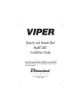
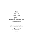
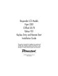
Remote Control
Internal
Antenna
Transmit
LED
Command
Buttons
AUX
Function
Button
4
Feature
Description
Internal Antenna
Used for transmitting information
Transmit LED
Active when transmitting information
Command buttons (4)
Used to perform locking, unlocking, auxiliary channel and
remote start commands
Function button
Used to access function levels for commands, configuration
menus for programming and Car Selection
© 2011 Directed Electronics. All rights reserved.
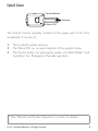
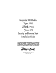
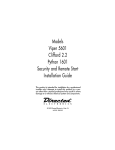
Control Center
Control button
Antenna
Status LED
The Control Center, typically located on the upper part of the front
windshield. It consists of:
s
s
s
The In-vehicle system antenna.
The Status LED, as a visual indicator of the system’s status.
The Control button, for placing the system into Valet Mode* and
to perform the Emergency Override operation.
* See “Remote and System Operations” section for details.
© 2011 Directed Electronics. All rights reserved.
5
Using your System
Commanding the system
Commands, Basic or Advanced, are used to activate system features
and are performed by pressing one of the Command buttons. Basic
commands control the most often used keyless entry and remote start
features while Advanced commands control more specialized features.
Confirmations for Basic or Advanced commands are indicated
by horn honks* and parking light flashes. A description of each feature confirmation is found in the following Basic command and Advanced command sections.
Performing Commands
Perform Basic commands by pressing a Command button.
Perform Advanced Commands by first accessing Levels 1-4 using the
button and then by pressing a Command button while within a
level.
Advanced command example: Silent Lock
1. Press the
button once to access Function Level 1, The transmit LED single flashes for 3 seconds.
2. Press the
button while the transmit LED is still flashing to
perform the Silent Lock command.
3. The system will lock the doors and flash the parking lights,
without horn honks.*
* The optional Horn Honk feature must be connected.
6
© 2011 Directed Electronics. All rights reserved.
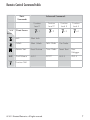
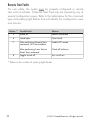
Remote Control Command table
Basic
Commands
Advanced Commands
Function
Level 1
Level
Direct Access
x1
Function
Level 2
x2
Function
Level 3
Function
Level 4
x3
x4
Button
Lock
Silent Lock
Unlock
Silent Unlock
Valet Mode
Car Finder
Remote Start
Reset Runtime
Timer Mode
Smart Start
Rear
Trunk Release
AUX 1
AUX 2
AUX 3
AUX 4
Defogger
AUX
Function Shift
© 2011 Directed Electronics. All rights reserved.
7
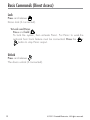
Basic Commands (Direct Access)
Lock
Press and release
Doors lock (if connected).
To Lock and Panic
Press and hold
To lock the system, then activate Panic. For Panic to work,the
optional horn honk feature must be connected. Press the
or
button to stop Panic output.
Unlock
Press and release
The doors unlock (if connected).
8
© 2011 Directed Electronics. All rights reserved.
Remote Start*
Press and release
Activates (or if On, deactivates) the remote starter. The engine turns
On, or the engine turns Off accordingly. If a Remote start configuration issue prevents the engine from starting, the parking lights flash a
Remote Start fault report to identify the fault.
AUX/Trunk**
Press and hold AUX
The Trunk opens (if connected) when this button is pressed for 2 seconds.
*For Manual transmission vehicles see “Manual Transmission
Vehicles”in the “Remote Start Features” section for more details.
**This is an optional feature. See your authorized Directed dealer
for details.
© 2011 Directed Electronics. All rights reserved.
9
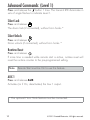
Advanced Commands: (Level 1)
Press and release the
button 1 time. The transmit LED illuminates in
sets of single flashes to indicate Level 1.
Silent Lock
Press and release
The doors lock (if connected), without horn honks.*
Silent Unlock
Press and release
Doors unlock (if connected), without horn honks.*
Runtime Reset
Press and release
If more time is needed while remote start is active, runtime reset will
reset the runtime counter to the pre-programmed setting.
Note
Remote Start must be On to use this feature.
AUX 1
Press and release AUX
Activates (or if On, deactivates) the Aux 1 output.
* The optional Horn Honk feature must be connected.
10
© 2011 Directed Electronics. All rights reserved.
Advanced Commands: (Level 2)
Press and release the
button 2 times. The transmit LED illuminates in
sets of double flashes to indicate Level 2.
Remote Valet
Press and release
Enters (or if On, exits) Valet Mode. The Control Center LED turns on
and off accordingly, and prevents doors from locking passively.
Timer Start*
Press and release
Activates (or if On, deactivates) Timer Start. The parking lights flash
quickly four times for On and slowly four times for Off.
Note
System needs to be locked with the remote or Timer Start
will not start the engine.
AUX 2
Press and release AUX
Activates (or if On, deactivates) the Aux 2 output.
* See “Advanced Start”under “Remote Start Features” for more details.
© 2011 Directed Electronics. All rights reserved.
11
Advanced Commands: (Level 3)
Press and release the
button 3 times. The transmit LED illuminates in
sets of triple flashes to indicate Level 3.
Car finder
Press and release
The horn emits one long honk and the parking lights flash for 10 seconds. The parking light flashes stop if locked or unlocked while Car
Finder is in progress. Lock and Unlock cancels the parking light flash.
Smart Start*
Press and release
Activates (or if On, deactivates) Smart Start. The parking lights flash
quickly five times for On and slowly five times for Off.
Note
System needs to be locked or Smart Start will not start the
engine.
AUX 3
Press and release AUX
Activates (or if On, deactivates) the Aux 3 output. See your authorized
Directed dealer for details.
* See “Advanced Start”under “Remote Start Features” for more details.
12
© 2011 Directed Electronics. All rights reserved.
Advanced Commands: (Level 4)
Press and release the
button 4 times. The transmit LED illuminates in
sets of quadruple flashes to indicate Level 4.
Defogger*
Press and release
Activates the vehicle Defogger circuit (if connected) while Remote Start
is activated and the parking lights flash 3 times. For convenience,
the Defogger circuit will also automatically activate 10 seconds after
remote starting if the temperature is below 55°F.
Note
Remote Start must be active to use this feature.
AUX 4
Press and release AUX
Activates (or if On, deactivates) the Aux 4 output.
* This feature must be installed and turned on by an authorized
Directed dealer.
© 2011 Directed Electronics. All rights reserved.
13
Remote Control Configuration
The remote controls have operations that can be configured to a user’s
personal preferences. The following instruction will direct you through
the available programming options for both remote controls.
Remote Programming
Enter programming, press and hold the
button for 8 seconds, the
transmit LED turns on to indicate the Main Menu is accessed.
Exit programming or go back to a previous menu, press and release
the
button. When programming is exited the transmit LED turns off.
Remote Pairing
The following instruction will step you through the remote pairing operation.
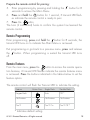
Prepare the vehicle system for pairing:
1. Turn the key to the ON position.
2. Within 5 seconds press and release 1 time the Control button on
the Control Center.
3. Within 5 seconds, press and hold the Control button. The status
LED will flash one time and the horn (if connected) honks once to
confirm the system is ready for remote pairing.
4. Release the Control button and proceed to next step.
Pairing will exit if:
s Step 7 is not completed within 60 seconds
s The doors are closed
s The ignition is turned off.
14
© 2011 Directed Electronics. All rights reserved.
Prepare the remote control for pairing:
5. Enter programming by pressing and holding the
button for 8
seconds to access the Main Menu.
6. Press and hold the
button for 1 second, 3 transmit LED flashes indicate the remote control is ready to pair.
7. Press the
button,
The horn (if connected) honks to confirm the system has learned the
remote control.
Remote Programming
Enter programming, press and hold the
button for 8 seconds, the
transmit LED turns on to indicate the Main Menu is accessed.
Exit programming or go back to a previous menu, press and release
the
button. When programming is exited the transmit LED turns
off.
Remote Features
From the main menu, press the
button to access the remote operation features, 2 transmit LED flashes indicate the remote features menu
is accessed. Press the buttons indicated in the tables below to set the
feature option.
The remote control will flash the Transmit LED to indicate the setting.
Feature
Button Press
Single Flash
Double Flash
Keypad Lock
Auto
Off *
No function
No function
No function
Car 2
Car 2 On
Car 2 Off *
* Indicates default setting.
© 2011 Directed Electronics. All rights reserved.
15
Keypad Lock
Options: Off, Auto
When Off, the buttons do not lock and always perform a command when pressed. When set to Auto, the remote buttons lock
after a 20 second lapse between button presses to prevent unintentional operations.
To unlock the buttons, press the
button followed by the
button.
Note
When the Keypad is locked, the remote control may appear to be non-operational. It will not transmit a command
or illuminate the Transmit LED and needs to be unlocked to
resume normal operation.
Car 2
Options: Off, On
The remote controls can control two systems independently.
When set to Off, the Car Select feature is not available. When
set to On the Car Select feature is enabled. See Car Select (under Remote and System Operations) for detail on using a remote
with 2 systems.
16
© 2011 Directed Electronics. All rights reserved.
Starter Kill Override
To bypass the optional Starter kill without a remote control:
Use the button on the Control Center to bypass the system. You can
bypass the system only if you have the vehicle key.
To check proper operation:
1. While the vehicle is locked, open the door. Immediately insert the
key into the ignition and turn it to the Run or On position. (all the
indicators in the dash turn on)
2. Press and release the Control button one time. The LED on the
Control Center will stop flashing and the optional Starter kill is
bypassed. You can now start the vehicle with the key.
Note: The override feature allows you to select a specific number of
presses needed to disable the system. If the override button has been
programmed to a new number of presses by your authorized dealer,
that number should be indicated below.
© 2011 Directed Electronics. All rights reserved.
17
Remote Start Features
Pit Stop Mode
To exit vehicle with engine running
The system keeps the engine running during short trips into the house
or convenience store. To perform Pit Stop:
1.
2.
3.
4.
With the engine running, set the parking brake and release the
foot brake.
Press the
button, the parking lights will turn on to indicate
remote start is on.
Turn the key to off, and remove it from the ignition, the engine
continues running for the programmed runtime.
Exit the vehicle and lock the system.
Note
For Pit Stop on manual transmission vehicles follow the
directions in the “Manual Transmission Start (MTS mode)”
section.
Key Takeover
When you are ready to drive
The system keeps the engine running until the vehicle is ready to be
driven. To perform Key Takeover:
1. Unlock the system and enter the vehicle, do not step on the foot
brake.
2. Insert the key, turn it to the run position, and then step on the foot
brake, the remote start then turns off.
3. The parking lights turn off to indicate remote start is off.
4. The vehicle is ready to drive.
18
© 2011 Directed Electronics. All rights reserved.
Remote Start Safe-lock
Remote start safe-lock makes sure the doors are locked while the engine is running and after, even if they are unlocked when remote start
is activated. Door locks may require additional parts and labor.
Disabling Remote Start
Remote start can be disabled by moving the Toggle Switch to the Off
position. If remote start is attempted while Off, the engine will not
start. (See “Remote Start Faults” under Remote Start Features) move the
switch back to the On position to resume normal operation.
Advanced Start
The Advanced start features; Timer Start and Smart Start will automatically start the engine to maintain battery charge or combat extreme
cold when parked for an extended period of time.
Precautions for the Advanced Start features:
s Park the vehicle in a well ventilated area away from windows
and doors that lead into inhabited spaces.
s Lock the vehicle, the engine will not start unless the doors are
locked.
s Only one Advanced start feature can be enabled at any given
time.
s For manual transmission vehicles MTS mode must be enabled
before Timer Start or Smart Start can be activated.
Timer Start operation
Activation begins a countdown timer as set by the installer (default 3 hours). When the timer expires the engine starts. When
the Remote start runtime expires the engine shuts off, and the
countdown timer restarts. This will repeat as many times as set
by the installer (default 6 starts). Timer Start is exited after the
final start.
© 2011 Directed Electronics. All rights reserved.
19
Smart Start operation
Smart Start uses the settings for Timer Start in addition to temperature and battery level to automatically start the engine. Activation
begins the countdown timer. When the timer expires the vehicle
interior temperature and battery level is checked and, if the Temperature is above 100F, below 0F, or the battery level is below 10.5v, the engine will start. When the Remote start runtime
expires the engine shuts off, and the countdown timer restarts.
Smart Start is exited after the final start.
Note
The temperature and battery thresholds can be changed by
an authorized Directed dealer if a higher or lower threshold
is desired.
Manual Transmission Start (MTS mode)
When installed into a manual transmission vehicle, the system requires
that the MTS mode is properly set when parking. If MTS mode is not
properly set or is defeated after being properly set the system will not
start the engine.
1.
2.
3.
20
With the engine running, set the parking brake and leave the
engine running.
For Pit Stop or Turbo Timer mode (to leave the engine running
after locking), open the driver door.
Release the foot brake (if pressed during Step 1), or press and
release the foot brake anytime. As long as the engine is running
there is no time limit to perform this step.
Within 20 seconds of foot brake release, press any command
button on the remote, after 20 seconds return to Step 2 (For Turbo
Timer Mode, press the optional dash mounted activation button
© 2011 Directed Electronics. All rights reserved.
4.
5.
6.
7.
or send the Timer Mode command.
The parking lights flash 5 times to confirm MTS mode is enabled
and the remote start activates the ignition outputs.
Turn Off and remove the key from the ignition switch, the engine
remains running.
Exit the vehicle, close all the doors and lock the system.
The engine turns off. If the door is opened in Step 1 then the
engine continues to run.
Turbo Timer Mode
The system keeps the engine running for the Turbo Timer runtime and
can be activated by remote control or optional dash mounted activation button.
1. With the engine running, set the parking brake.
2. Press the optional dash mounted activation button or perform the
Timer Mode command.
3. The parking lights turn on and the remote start activates the ignition outputs.
4. Turn Off and remove the key from the ignition switch, the engine
remains running.
5. Exit the vehicle, close all the doors and lock the system.
6. The engine runs for the Turbo Mode runtime.
Note
Turbo Timer must be turned on by an authorized Directed
dealer.
© 2011 Directed Electronics. All rights reserved.
21
Remote Start Faults
For user safety, the system must be properly configured or remote
start will not activate. A Remote Start Fault may be caused by any of
several configuration issues. Refer to the table below for the command
type and parking light flashes that will identify the configuration issue
and solution.
Flashes *
Possible Fault
Solution
5
Brake on
Release foot brake
6
Hood open
Close hood
7
After performing Remote Start
command - MTS not enabled
Enable MTS mode
After performing Timer Start or
Smart Start command
Check all Solutions
Toggle Switch off
Turn switch on
8
* Refers to the number of parking light flashes.
22
© 2011 Directed Electronics. All rights reserved.
Remote and System Operations
Passive Locking*
Park and exit the vehicle, after the doors are closed the Passive locking countdown begins. The led flashes quickly and upon reaching
20 seconds the siren then chirps once. At 30 seconds the system
activates itself.
Anytime before the system locks you can re-enter the vehicle or
open the trunk to load or unload items and, after closing passive locking resumes.
To stay secure in case of accidental unlocking the system, if a
door is not opened within 30 seconds the system reactivates itself and
locks the doors.
Auto Re-locking*
Auto re- ensures the vehicle stays locked if it is not entered after unlocking by remote control. After unlocking by remote, the system automatically re-locks the doors (if programmed on) in 30 seconds. Open any
point of entry to stop the re-lock until the next unlock by remote.
Onetime Bypass*
Turn the ignition On for one to three seconds and then Off. The horn
honks once to confirm one-time bypass is enabled.
One-time bypass can be used to temporarily bypass the Passive locking operation for one cycle. It also bypasses the comfort closure and
auxiliary channel outputs if programmed to activate when locking.
After the next unlock, all operations return to normal.
* The optional horn honk feature must be installed.
© 2011 Directed Electronics. All rights reserved.
23
Valet Mode
Valet mode can be entered and exited by performing the Remote Valet
command or manually using the vehicle key and the control button.
Use
1.
2.
3.
the following steps to manually enter and exit Valet Mode:
Turn the ignition switch On and then Off
Immediately press and release the control button once
The control center LED turns On when entering and Off when
exiting.
Power Save
To reduce power consumption the control center status LED modifies
its output if the vehicle is parked for an extended period. If Locked the
flashing is reduced after 24 hours. When Valet mode is On the LED
turns off after 1 hour and resets each time the ignition is turned off.
Rapid Resume
If power is ever disconnected by a mechanic or thief, the system will
resume the state it was in at the time of disconnection, when power
is reconnected.
Car Select
Car 2 remote control option must first be turned On (See Remote
Control Configuration section to turn on). Press and hold the
button
for 3 seconds. The LED flashes once or twice to indicate the selected
Car is 1 or 2, release the button for Car Select or continue to hold
for programming.
Release the
button, then press and release while the LED flashes continue to perform Car Select. Once the car is selected a command can be performed by pressing one of the command buttons.
24
© 2011 Directed Electronics. All rights reserved.
System Expansion Options
Controlling two vehicles (Car Select)
The remote controls can control systems in two different vehicles saving the need for multiple remote controls. This feature also allows for
customized system configurations on each vehicle that has more than
one driver. See Owner Recognition for details.
Owner recognition *
The system can be configured to recognize the remote used when
unlocking and change selected features to match the remote users
preferences. Memory seat adjustment, horn honks, passive locking,
remote button auto unlocking, horn output duration can all be custom
set for each remote user at the time of installation.
Comfort closure *
Comfort Closure emulates turning the key in the door cylinder or holding the lock button of an OEM keyless entry. It will automatically close
the windows and sunroof on vehicles with this type of OEM convenience feature.
Driver door priority unlocking *
The door unlocking operation can be configured to emulate an OEM
style of driver priority unlocking for added protection during unocking.
* These features must be turned on by an authorized Directed dealer.
© 2011 Directed Electronics. All rights reserved.
25
Battery Information
The remote controls are powered by 1 coin cell battery (CR-2032)
that can be purchased at most retailers. When the battery begins to
weaken, the operating range will be reduced. The information and
precautions in this section can help maximize your battery’s life and
usage in providing you with many years of trouble free operation.
Low Battery Alerts
When unlocking the system using a remote with a low battery the
horn emits one additional honk as an alert. If confirmation honks are
programmed off, the system will still emit one honk as an alert when
unlocking. The optional horn honk feature must be installed.
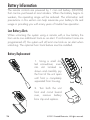
Battery Replacement
1. Using a small slotted screwdriver, insert
into slot located as
shown and carefully pry
the front of the unit open
until front is completely
separated from housing.
26
+
+
2. Turn both the unit
front and circuit board
over, remove battery
from clip and replace.
Detail
© 2011 Directed Electronics. All rights reserved.
Note
3.
Verify that the battery ploarity is correct when replacing.
With the front and circuit board stil turned over, turn back portion
of unit onto both parts, reposition all parts and snap together.
Battery Disposal
Directed Electronics cares about the environment. If you
need to dispose of the battery, please do so in accordance
with your municipal requirements for battery disposal or return to Directed Electronics at: One Viper way, Vista, CA
92081 (Shipping and/or handling costs are the sole responsibility of
the owner/sender and will not be covered by Directed Electronics).
© 2011 Directed Electronics. All rights reserved.
27
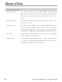
Glossary of Terms
Document Terminology
28
Control Module
The “brain” of your system. Usually hidden underneath the
dash area of the vehicle. It houses the microprocessor which
monitors your vehicle and controls all of the system’s functions.
Remote Control
A hand-held, remote control which operates the various functions of your system.
Control Center
The control center contains the system’s radio-frequency antenna, the control button, and the Status LED. For maximum
remote-control range, the control center is usually located at
the top of the windshield, centered near the rear-view mirror.
Status LED
A light used to indicate the status of your system. It is located
on your system’s Control Center.
Control Button
A small push button located on your system’s control center.
It is used to override (disarm) the alarm when a remote is not
available or to enter or exit Valet Mode.
© 2011 Directed Electronics. All rights reserved.
Government Regulations
This device complies with Part 15 of FCC rules. Operation is subject to the following two conditions: (1) This device may not cause harmful interference, and
(2) This device must accept any interference received, including interference
that may cause undesirable operation.
This equipment has been tested and found to comply with the limits for a
class B digital device, pursuant to Part 15 of the FCC Rules. These limits are
designed to provide reasonable protection against harmful interference in a
residential installation. This equipment generates and can radiate radio frequency energy and, if not installed and used in accordance with the instruction
manual, may cause harmful interference to radio communications. However,
there is no guarantee that interference will not occur in a particular installation. If this equipment does cause harmful interference to radio or television,
which can be determined by turning the equipment OFF and ON, the user is
encouraged to try to correct the interference by one or more of the following
measures:
s2EORIENTORRELOCATETHERECEIVINGANTENNA
s)NCREASETHESEPARATIONBETWEENTHEEQUIPMENTANDRECEIVER
s#ONNECTTHEEQUIPMENTINTOANOUTLETONACIRCUITDIFFERENTFROMTHATTOWHICH
the receiver is connected.
s#ONSULTTHEDEALERORANEXPERIENCEDRADIO46TECHNICIANFORHELP
This device complies with the Industry Canada Radio Standards Specification
RSS 210. Its use is authorized only on a no-interference, no-protection basis;
in other words, this device must not be used if it is determined that it causes
harmful interference to services authorized by IC. In addition, the user of this
device must accept any radio interference that may be received, even if this
interference could affect the operation of the device.
WARNING! Changes or modifications not expressly approved by the party responsible for compliance could void the user’s authority to operate this device.
© 2011 Directed Electronics. All rights reserved.
29
Warning! Safety First
Please read the safety warnings below before proceeding. Improper
use of the product may be dangerous or illegal.
Installation
Due to the complexity of this system, installation of this product must only be
performed by an authorized Directed dealer. If you have any questions, ask
your retailer or contact Directed directly at 1-800-753-0600.
Remote Start Capable
When properly installed, this system can start the vehicle via a command
signal from the remote control transmitter. Therefore, never operate the system
in an enclosed area or partially enclosed area without ventilation (such as a
garage). When parking in an enclosed or partially enclosed area or when
having the vehicle serviced, the remote start system must be disabled using the
installed menu wheel. It is the user’s sole responsibility to properly handle and
keep out of reach from children all remote control transmitters to assure that the
system does not unintentionally remote start the vehicle. THE USER MUST INSTALL A CARBON MONOXIDE DETECTOR IN OR ABOUT THE LIVING AREA
ADJACENT TO THE VEHICLE. ALL DOORS LEADING FROM ADJACENT LIVING AREAS TO THE ENCLOSED OR PARTIALLY ENCLOSED VEHICLE STORAGE AREA MUST AT ALL TIMES REMAIN CLOSED. These precautions are the
sole responsibility of the user.
Manual Transmission Vehicles
Remote starters on manual transmission vehicles operate differently than
those with automatic transmission because you must leave your car in neutral.
You must read this Owner’s Guide to familiarize yourself with the proper procedures regarding manual transmission remote starters. If you have any questions,
ask your authorized Directed dealer or contact Directed at 1-800-753-0600.
30
© 2011 Directed Electronics. All rights reserved.
Before remote starting a manual transmission vehicle, be sure to:
s Leave the vehicle in neutral and be sure no one is standing in front or
behind the vehicle.
s Only remote start on a flat surface
s Have the parking brake fully engaged
WARNING! It is the responsibility of the owner to ensure the parking/emergency brake properly functions. Failure to do so can result in personal injury or
property damage. We recommend the owner have the parking / emergency
brake system inspected and adjusted by a qualified automotive shop biannually.
Use of this product in a manner contrary to its intended mode of operation may
result in property damage, personal injury, or death. (1) Never remotely start
the vehicle with the vehicle in gear, and (2) Never remotely start the vehicle
with the keys in the ignition. The user must also have the neutral safety feature
of the vehicle periodically checked, wherein the vehicle must not remotely start
while the car is in gear. This testing should be performed by an authorized
Directed dealer in accordance with the Safety Check outlined in the product
installation guide. If the vehicle starts in gear, cease remote start operation immediately and consult with the authorized Directed dealer to fix the problem.
After the remote start module has been installed, contact your authorized dealer
to have him or her test the remote start module by performing the Safety Check
outlined in the product installation guide. If the vehicle starts when performing
the Neutral Safety Shutdown Circuit test, the remote start unit has not been
properly installed. The remote start module must be removed or the installer
must properly reinstall the remote start system so that the vehicle does not start
in gear. All installations must be performed by an authorized Directed dealer.
OPERATION OF THE REMOTE START MODULE IF THE VEHICLE STARTS IN
© 2011 Directed Electronics. All rights reserved.
31
GEAR IS CONTRARY TO ITS INTENDED MODE OF OPERATION. OPERATING THE REMOTE START SYSTEM UNDER THESE CONDITIONS MAY
RESULT IN PROPERTY DAMAGE OR PERSONAL INJURY. YOU MUST IMMEDIATELY CEASE THE USE OF THE UNIT AND SEEK THE ASSISTANCE OF
AN AUTHORIZED Directed DEALER TO REPAIR OR DISCONNECT THE INSTALLED REMOTE START MODULE. DIRECTED WILL NOT BE HELD RESPONSIBLE OR PAY FOR INSTALLATION OR REINSTALLATION COSTS.
This product is designed for fuel injected vehicles only. Use of this
product in a standard transmission vehicle must be in strict accordance
with this guide.
This product should not be installed in any convertible vehicles, soft or
hard top with a manual transmission. Installation in such vehicles may
pose certain risk.
Interference
All radio devices are subject to interference which could affect proper
performance.
Upgrades
Any upgrades to this product must be performed by an authorized
Directed dealer. Do not attempt to perform any unauthorized modifications to this product.
Water/Heat Resistance
This product is not designed to be water and/or heat-resistant. Please
take care to keep this product dry and away from heat sources. Any
damage from water or heat will void the warranty.
32
© 2011 Directed Electronics. All rights reserved.
Limited lifetime consumer warranty
Directed Electronics. (“Directed”) promises to the original purchaser to repair or replace
(at Directed’s election) with a comparable reconditioned model any Directed unit (hereafter the “unit”), excluding without limitation the siren, the remote transmitters, the associated
sensors and accessories, which proves to be defective in workmanship or material under
reasonable use during the lifetime of the vehicle provided the following conditions are met:
the unit was purchased from an authorized Directed dealer, the unit was professionally
installed and serviced by an authorized Directed dealer; the unit will be profession¬ally
reinstalled in the vehicle in which it was originally installed by an authorized Directed
dealer; and the unit is returned to Directed, shipping prepaid with a legible copy of the
bill of sale or other dated proof of purchase bearing the following information: consumer’s
name, telephone number and address; the authorized dealers name, telephone number
and address; complete product description, including accessories; the year, make and
model of the vehicle; vehicle license number and vehicle identification number. All components other than the unit, including without limitation the siren, the remote transmitters
and the associated sensors and accessories, carry a one-year warranty from the date of
purchase of the same. ALL PRODUCTS RECEIVED BY DIRECTED FOR WARRANTY REPAIR
WITHOUT PROOF OF PURCHASE FROM AN AUTHORIZED DEALER WILL BE DENIED.
This warranty is non-transferable and is automatically void if: the unit’s date code or serial
number is defaced, missing or altered; the unit has been modified or used in a manner
contrary to its intended purpose; the unit has been damaged by accident, unreasonable
use, neglect, improper service, installation or other causes not arising out of defects in
materials or construction. The warranty does not cover damage to the unit caused by
installation or removal of the unit. Directed, in its sole discretion, will determine what constitutes excessive damage and may refuse the return of any unit with excessive damage.
TO THE MAXIMUM EXTENT ALLOWED BY LAW, ALL WARRANTIES, INCLUDING
BUT NOT LIMITED TO EXPRESS WARRANTY, IMPLIED WARRANTY, WARRANTY
OF MERCHANTABILITY, FITNESS FOR PARTICULAR PURPOSE AND WARRANTY OF
NON-INFRINGEMENT OF INTELLECTUAL PROPERTY, ARE EXPRESSLY EXCLUDED;
AND DIRECTED NEITHER ASSUMES NOR AUTHORIZES ANY PERSON OR ENTITY
TO ASSUME FOR IT ANY DUTY, OBLIGATION OR LIABILITY IN CONNECTION
WITH ITS PRODUCTS. DIRECTED DISCLAIMS AND HAS ABSOLUTELY NO LIABILITY
FOR ANY AND ALL ACTS OF THIRD PARTIES INCLUDING ITS AUTHORIZED
DEALERS OR INSTALLERS. DIRECTED SECURITY SYSTEMS, INCLUDING THIS UNIT,
ARE DETERRENTS AGAINST POSSIBLE THEFT. DIRECTED IS NOT OFFERING A
GUARANTEE OR INSURANCE AGAINST VANDALISM, DAMAGE OR THEFT OF THE
AUTOMOBILE, ITS PARTS OR CONTENTS; AND HEREBY EXPRESSLY DISCLAIMS ANY
LIABILITY WHATSOEVER, INCLUDING WITHOUT LIMITATION, LIABILITY FOR THEFT,
DAMAGE AND/OR VANDALISM. THIS WARRANTY DOES NOT COVER LABOR
COSTS FOR MAINTENANCE, REMOVAL OR REINSTALLATION OF THE UNIT OR
© 2011 Directed Electronics. All rights reserved.
33
ANY CONSEQUENTIAL DAMAGES OF ANY KIND. IN THE EVENT OF A CLAIM
OR A DISPUTE INVOLVING DIRECTED OR ITS SUBSIDIARY, THE VENUE SHALL BE
SAN DIEGO COUNTY IN THE STATE OF CALIFORNIA. CALIFORNIA STATE LAWS
AND APPLICABLE FEDERAL LAWS SHALL APPLY AND GOVERN THE DISPUTE. THE
MAXIMUM RECOVERY UNDER ANY CLAIM AGAINST DIRECTED SHALL BE STRICTLY
LIMITED TO THE AUTHORIZED DIRECTED DEALER’S PURCHASE PRICE OF THE UNIT.
DIRECTED SHALL NOT BE RESPONSIBLE FOR ANY DAMAGES WHATSOEVER,
INCLUDING BUT NOT LIMITED TO, ANY CONSEQUENTIAL DAMAGES, INCIDENTAL
DAMAGES, DAMAGE TO VEHICLE, DAMAGES FOR THE LOSS OF TIME, LOSS OF
EARNINGS, COMMERCIAL LOSS, LOSS OF ECONOMIC OPPORTUNITY AND THE
LIKE. NOTWITHSTANDING THE ABOVE, THE MANUFACTURER DOES OFFER A
LIMITED WARRANTY TO REPLACE OR REPAIR THE CONTROL MODULE SUBJECT TO
THE CONDITIONS AS DESCRIBED HEREIN. THIS WARRANTY IS VOID IF THE UNIT
HAS NOT BEEN PURCHASED FROM DIRECTED, OR AN AUTHORIZED DIRECTED
DEALER, OR IF THE UNIT HAS BEEN DAMAGED BY ACCIDENT, UNREASONABLE
USE, NEGLIGENCE, ACTS OF GOD, NEGLECT, IMPROPER SERVICE, OR OTHER
CAUSES NOT ARISING OUT OF DEFECT IN MATERIALS OR CONSTRUCTION.
Some states do not allow limitations on how long an implied warranty will last or the
exclusion or limitation of incidental or consequential damages. This warranty gives you
specific legal rights and you may also have other rights that vary from State to State.
This warranty is only valid for sale of product(s) within the United States of America and
in Canada. Product(s) sold outside of the United States of America or Canada are sold
“AS-IS” and shall have NO WARRANTY, express or implied.
For further details relating to warranty information of Directed products, please visit the
support section of Directed’s website at: www.directed.com
This product may be covered by a Guaranteed Protection Plan (“GPP”). See your
authorized Directed dealer for details of the plan or call Directed Customer Service at
1-800-876-0800.
920-10011-01-2011-06
34
© 2011 Directed Electronics. All rights reserved.
Models
Viper 4104
Clifford 410.4X
Python 414
Keyless Entry and Remote Start
Installation Guide
This product is intended for installation by a professional
installer only! Attempts to install this product by a person other than a trained professional may result in severe
damage to a vehicle’s electrical system and components.
© 2011 Directed Electronics, Vista, CA
N4104 2011-10
Bitwriter®, Code Hopping™, Doubleguard®, ESP™, FailSafe®, Ghost Switch™, Learn Routine™, Nite-Lite®, Nuisance
Prevention® Circuitry, Revenger®, Silent Mode™, Soft Chirp®,
Stinger®, Valet®, Vehicle Recovery System®, VRS®, and Warn
Away® are all Trademarks or Registered Trademarks of Directed Electronics.
The
Bitwriter®
(p/n
998U) requires chip
version 2.7 or newer to
program this unit.
Bitwriters with a date code of 6a or older require an IC upgrade (p/n
998M). Some Bitwriters with a date code of 6B do not require the IC
upgrade, refer to tech tip # 1112 for more information.
Contents
Warning! safety first......................................................................................................................... 4
Wiring Diagram.............................................................................................................................. 5
Wiring Connections......................................................................................................................... 6
Main Harness (H1), 6-pin connector............................................................................................. 6
Auxiliary/Shutdown Harness (H2), 24-pin connector...................................................................... 6
Remote Start (H3), 8-pin connector............................................................................................. 7
Door Lock, 3-pin connector.......................................................................................................... 7
Initializing Virtual Tach (not needed w/hardwire tach inputs)................................................................. 7
Learning the Tach (not needed with Virtual Tach).................................................................................. 7
Neutral safety switch interface........................................................................................................... 8
Testing the neutral safety switch.................................................................................................... 8
Remote Start Shutdown/Startup Diagnostics........................................................................................ 8
Remote Pairing................................................................................................................................ 9
Programming System Features......................................................................................................... 10
Feature Menus............................................................................................................................... 11
Menu 1 - Vehicle integration...................................................................................................... 11
Menu 2 - Convenience.............................................................................................................. 13
Menu 3 - Remote start............................................................................................................... 15
Bitwriter - Only Options.................................................................................................................. 17
Basic Remote Functions................................................................................................................... 19
Reset and Deletion......................................................................................................................... 19
Troubleshooting: Keyless Entry......................................................................................................... 20
Troubleshooting: Remote Start.......................................................................................................... 20
Warning! safety first
The following safety warnings must be observed at all times:
• Due to the complexity of this system, installation of this product must only be performed by an authorized
Directed Electronics dealer.
• When properly installed, this system can start the vehicle via a command signal from the remote control.
Therefore, never operate the system in an area that does not have adequate ventilation.
The following precautions are the sole responsibility of the user; however, authorized Directed Electronics
dealers should:
• Never use a test light or logic probe when installing this unit. Always use a multimeter.
• Never operate the system in an enclosed or partially enclosed area without ventilation (such as a garage).
• When parking in an enclosed or partially enclosed area or when having the vehicle serviced, the remote
start system must be disabled using the installed toggle switch. It is the user’s sole responsibility to properly handle and keep out of reach from children all remote controls to assure that the system does not
unintentionally remote start the vehicle.
• USER MUST INSTALL A CARBON MONOXIDE DETECTOR IN OR ABOUT THE LIVING AREA ADJACENT
TO THE VEHICLE. ALL DOORS LEADING FROM ADJACENT LIVING AREAS TO THE ENCLOSED OR PARTIALLY ENCLOSED VEHICLE STORAGE AREA MUST REMAIN CLOSED AT ALL TIMES.
Use of this product in a manner contrary to its intended mode of operation may result in property damage,
personal injury, or death. Except when performing the Safety Check outlined in this installation guide, (1)
Never remotely start the vehicle with the vehicle in gear, and (2) Never remotely start the vehicle with the
keys in the ignition. The user is responsible for having the neutral safety feature of the vehicle periodically
checked, wherein the vehicle must not remotely start while the car is in gear. This testing should be performed
by an authorized Directed Electronics dealer in accordance with the Safety Check outlined in this product
installation guide. If the vehicle starts in gear, cease remote start operation immediately and consult with the
user to fix the problem immediately.
After the remote start module has been installed, test the remote start module in accordance with the Safety
Check outlined in this installation guide. If the vehicle starts when performing the Neutral Safety Shutdown
Circuit test, the remote start unit has not been properly installed. The remote start module must be removed
or properly reinstalled so that the vehicle does not start in gear. All installations must be performed by an
authorized Directed Electronics dealer.
OPERATION OF THE REMOTE START MODULE IF THE VEHICLE STARTS IN GEAR IS CONTRARY TO ITS INTENDED MODE OF OPERATION. OPERATING THE REMOTE START SYSTEM UNDER THESE CONDITIONS
MAY RESULT IN PROPERTY DAMAGE OR PERSONAL INJURY. IMMEDIATELY CEASE THE USE OF THE UNIT
AND REPAIR OR DISCONNECT THE INSTALLED REMOTE START MODULE. DIRECTED ELECTRONICS WILL
NOT BE HELD RESPONSIBLE OR PAY FOR INSTALLATION OR REINSTALLATION COSTS.
Remote starters for manual transmission pose significant risks if not properly installed and operated. When
testing to ensure the installation is working properly, only remote start the vehicle in neutral gear, on a flat
surface and with a functional, fully engaged parking brake. Do not allow anyone to stand in front of or behind
the vehicle.
This product should not be installed in any convertible vehicles, soft or hard top with a manual transmission.
Installation in such vehicles may pose certain risk.
4
© 2011 Directed Electronics. All rights reserved.
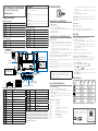
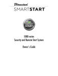
Valet switch
Control button
LED
Status LED
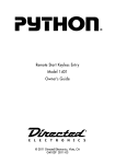
Control Center
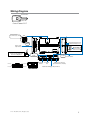
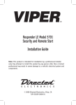
Wiring
Diagram
r
Valet switch
Control button
LED
Status LED
er
Control Center
Control
Center 6111T
er
Control Center
LIGHT FLASH POLARITY
(10A (MAXIMUM) FUSE JUMPER)
Thermistor/Temp Sensor
+
Remote Start
8-pin Harness
Bitwriter/SmartStart Port
10A FUSE
MINI ATM
RPN: 8540
-
4x04
IMPORTANT! Neutral Safety
switch must be plugged in
and in the ON position
PINK/WHITE
1 3 5
BLACK/WHITE
2 4 6
24 GREEN/WHITE
INSERTION/WIRE SIDE
ON
23 VIOLET/WHITE
© 2011 Directed Electronics. All rights reserved.
Neutral Safety
Switch
RF Port
for IVU
Main 6-pin
Harness
Door Lock
Port
Horn Input
Polarity Jumper
Control Center
D2D Port (for external
Xpresskit interface module)
Aux/Shutdown/Trigger 24-pin Harness
5
Wiring Connections
Main Harness (H1), 6-pin connector
H1/1
RED
(+)12VDC CONSTANT INPUT
H1/2
BLACK
(-) CHASSIS GROUND
H1/3
BROWN
(-) 200mA HORN HONK OUTPUT
H1/4
WHITE/BROWN
LIGHT FLASH ISOLATION WIRE - PIN 87a light flash relay
H1/5
WHITE
PIN 30 of LIGHT FLASH RELAY
H1/6
ORANGE
500 mA GROUND WHEN ARMED OUTPUT
Auxiliary/Shutdown Harness (H2), 24-pin connector
H2/1
PNK/WHITE
(-) 200mA FLEX RELAY CONTROL OUTPUT
H2/2
BLACK/WHITE
(-) NEUTRAL SAFETY INPUT
H2/3
BLUE/WHITE
(-) 200mA 2ND STATUS /REAR DEFOGGER OUTPUT
H2/4
GREEN/BLACK
(-) 200mA FACTORY ALARM DISARM OUTPUT
H2/5
RED/WHITE
(-) 200mA TRUNK RELEASE OUTPUT
H2/6
GREEN
(-) DOOR INPUT*
H2/7
BLACK/YELLOW
(-) 200mA DOME LIGHT OUTPUT
H2/8
EMPTY
-----------------------------------(-) 200mA STATUS OUTPUT
H2/9
DARK BLUE
H2/10
PINK
(-) 200mA IGNITION 1 OUTPUT
H2/11
WHITE/BLACK
(-) 200mA AUX 3 OUTPUT
H2/12
VIOLET
(+) DOOR INPUT
H2/13
WHITE/VIOLET
(-) 200mA AUX 1 OUTPUT
H2/14
VIOLET/BLACK
(-) 200mA AUX 2 OUTPUT
H2/15
ORANGE/BLACK
(-) 200mA AUX 4 OUTPUT
H2/16
BROWN
(+) BRAKE SHUTDOWN INPUT
H2/17
GRAY
(-) HOOD PIN INPUT (NC OR NO)
H2/18
VIOLET/YELLOW
(-) 200mA STARTER OUTPUT
H2/19
BLUE**
FACTORY HORN INPUT (Use Jumper to set polarity)
H2/20
GRAY/BLACK
(-) DIESEL WAIT TO START INPUT
H2/21
WHITE/BLUE
ACTIVATION INPUT
(-) 200mA ACCESSORY OUTPUT
H2/22
ORANGE
H2/23
VIOLET/WHITE
TACHOMETER INPUT
H2/24
GREEN/WHITE
(-) 200mA FACTORY ALARM ARM OUTPUT
*The Normally Closed setting will only work if one of the vehicle's doors is connected. If more than one door
is to be monitored, then it is recommended to use the Xpresskit DTIMAZDA or tech tip # 1921 on www.directechs.com to interface with these types of vehicles.
**This optional input can be connected to the horn circuit (+ or -). When this wire receives input for a minimum of
.5 seconds, the system reports a trigger on the 2-way remote. This is useful on vehicles that have a factory security
system that can be armed/disarmed with the Directed system. This system will not report that a zone has been
triggered when unlocking with the 2-way remote. This feature is not available on the 1-way remote.
6
© 2011 Directed Electronics. All rights reserved.
Remote Start (H3), 8-pin connector
H3/1
PINK
(+) IGNITION 1 INPUT/OUTPUT
H3/2
RED/WHITE
+12V FUSED (30A) IGNITION 2/FLEX RELAY INPUT
H3/3
ORANGE
(+) ACCESSORY OUTPUT
H3/4
VIOLET
(+) STARTER OUTPUT
H3/5
RED
+12V FUSED (30A) IGNITION 1 INPUT
H3/6
PINK/WHITE
IGNITION 2/FLEX RELAY OUTPUT
H3/7
PINK/BLACK
FLEX RELAY INPUT 87a (IF REQUIRED) OF FLEX RELAY
H3/8
RED/BLACK
+12V FUSED (30A) ACCESSORY/STARTER INPUT
Door Lock, 3-pin connector
1
BLUE
(-) 500mA UNLOCK OUTPUT
2
EMPTY
NOT USED
3
GREEN
(-) 500mA LOCK OUTPUT
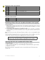
Initializing Virtual Tach (not needed w/hardwire tach inputs)
To program Virtual Tach:
1. After the install is complete, remote start the engine. The programming operation may require 3 cranks of
the starter before the engine starts and runs. Do not turn off the remote start if this happens, it is a normal
programming operation.
2. Once the engine begins running, let it run for at least 30 seconds.
3. Using the Remote, send the Remote start command to turn remote start off. Virtual Tach is programmed.
To reset Virtual Tach, go into the Reset and Deletion section of this guide. Virtual Tach cannot be reset with
the Bitwriter.
Note: Virtual Tach cannot be used in MTS Manual Transmission Mode. It is also not recommended for diesel
trucks.
Virtual Tach handles disengaging the starter motor during remote starting – it does not address over-rev. If the
customer wants to have the over-rev protection capability, the tach wire must be connected.
Important: After successfully learning Virtual Tach, a small minority of vehicle starters
may over crank or under crank during remote start. The Bitwriter can be used fine tune
the starter output time in 50mS increments to compensate for such an occurrence.
Learning the Tach (not needed with Virtual Tach)
To learn the tach signal:
1. Start the vehicle with the key. Within 5 seconds, press and hold the Control button.
2. After 3 seconds the status LED on your Control Center lights constant when the tach signal is learned.
3. Release the Control button.
Note: When the tachometer is programmed, the main unit automatically enters the Tachometer engine
checking mode.
© 2011 Directed Electronics. All rights reserved.
7
Neutral safety switch interface
Some vehicles do not have an electrical neutral safety switch. Instead, the vehicle has a mechanical neutral
safety switch that physically interrupts the starter wire and is used when the vehicle is in any drive gear. If the
remote start is interfaced before this switch, it will provide protection from starting in gear. However, some
vehicles combine the column shift mechanism and the mechanical neutral safety switch into one mechanical
part.
Important: You must complete the remote start system installation before doing the following test. Ensure that the remote start system is functioning normally. This includes connecting to the brake as a shut-down.
Testing the neutral safety switch
1.
2.
3.
4.
5.
6.
Make sure there is adequate clearance to the front and rear of the vehicle because it may move slightly.
Make sure the hood is closed and there are no remote start shut-downs active.
Set the emergency brake.
Turn the key to the “run” position, this releases the shifter.
Place the car in drive (D).
Place your foot directly over the brake pedal, but do not depress it. Be ready to step on the brake if the
starter engages.
7. Activate the remote start system.
8. If the starter engages, immediately depress the brake to shut the remote start system down. If the
starter does not engage, no additional safety system is required.
If the starter engages and the vehicle is a General Motors product or Dodge Dakota pickup, refer to
www.directechs.com for Document 1008 under the Resource tab. For an alternative shut-down method
which prevents the starter from engaging. If the vehicle is not a General Motors product or a Dodge
Dakota pickup, please call Directed Electronics Technical Support for an alternative shut-down method.
Do not return the vehicle to the customer until this feature is properly installed!
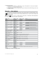
Remote Start Shutdown/Startup Diagnostics
Shutdown diagnostics: If the remote start activates but fails to stay running, the remote start module has the
ability to inform you of what may have caused the remote start failure. Before performing shutdown diagnostics it is important that you let the remote start shut off on its own i.e. let it attempt to start 3 times then shut
down, if this is not done the unit will report the shutdown you used to shut off the remote start.
Note: Shutdown diagnostics does not report if the vehicles factory immobilizer is causing the problem.
To perform shutdown diagnostics:
1. With the ignition Off, press and hold the Control button (on Control Center).
2. Turn the ignition On and then back Off while holding the Control button.
3. Release the Control button.
4. Press and release the Control button. The status LED flashes to report the last shutdown for one minute or
until the ignition is turned on, as shown in the following table:
Status LED Flashes
Shutdown Mode
1 flash
Runtime expired
2 flashes
Over-rev shutdown
3 flashes
Low or no RPM
4 flashes
Transmitter shutdown (or optional push button)
5 flashes
(+) Brake shutdown
6 flashes
(-) Hood shutdown
7 flashes
Timer mode/Turbo mode/Manual mode error *
8 flashes
Neutral safety shutdown
9 flashes
Low battery (voltage mode)
11 flashes
Wait-to-start input timed out
* Timer mode error: Ignition is on or shutdown input is active when activating timer mode.
Turbo mode error: Turbo mode is programmed off, engine is not on or shutdown input is active.
Manual mode error: MTS mode not enabled.
8
© 2011 Directed Electronics. All rights reserved.
Startup Diagnostics: If the vehicle fails to activate the remote start, the remote start module will flash the parking lights on the vehicle to notify you of what caused the no-start situation.
Parking Light Flashes
5 flashes
6 flashes
7 flashes
8 flashes
Brake wire is active
Hood pin wire is active
Manual transmission mode is enabled and not initialized.
Neutral safety wire has no ground or the neutral safety switch is Off.
Remote Pairing
Prepare the vehicle system to be Paired with a new remote
1. Turn the key to the ON position.
2. Within 5 seconds press and release the Control button on the system’s Control Center one time.
3. Within 5 seconds, press and hold the Control button on the Control Center. The status LED will flash one
time and the horn honks and the LED flashes to confirm the vehicle is ready for remote pairing.
4. Release the Control button and proceed below.
Note: If no remote pairing results, the system will exit after 60 seconds.
Prepare the 1-way remote control to be Paired with the system:
Make sure the remote is set for the desired Car 1 (Default) or Car 2 operation for the system it will be paired
with.
AUX
1. Press and hold the
button for 8 seconds.
Note: If Car 2 mode is on, ignore the Car Select indicator after 3 seconds.
2. Wait for the Transmit LED to light solid. Release the
button.
3. Press the
button for 1 second. The transmit LED will blink 3 times.
4. Within 5 seconds, press the
button.
5. The vehicle horn will honk. You have now successfully learned the remote to the vehicle remote start and
keyless entry system.
6. Press the
button two times to exit learn routine on the remote. The transmit LED will turn off when exiting.
AUX
AUX
AUX
AUX
© 2011 Directed Electronics. All rights reserved.
9
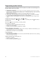
Programming System Features
The System Features Learn Routine dictates how the unit operates. It is possible to access and change most of
the feature settings using the Control button.
1. Turn the ignition on, then off.
2. Select a Menu. Press and hold the Control button. The number of LED flashes and horn honks indicates
the menu number. 1 LED flash and honk indicates menu 1, 2 LED flashes and honks - menu 2 and 3 LED
flashes and honks for menu 3.
3. When the desired menu LED flashes and honks are observed, release the Control button.
4. Select a Feature. Press and release the Control button the number of times corresponding to the feature
you wish to change. Then press and hold one more time to select the features.
5. Program the Feature. While holding the Control button, you can program the feature using the remote
control.
For features with only two options;
= option 1 while
= option 2.
For features with more than two options;
selects the options in ascending order, while
descending order.
AUX
Note: Pressing
selects them in
AUX
AUX
AUX
button resets the feature to the factory default.
AUX
Once a feature is programmed:
• Other features can be programmed within the same menu
• Another menu can be selected
• The learn routine can be exited if programming is complete
To access another feature in the same menu:
1. Press and release the Control button the number of times necessary to advance from the feature you just
programmed to the next one you want to program.
2. Then press the Control button once more and hold it.
To select another menu:
1. Press and hold the Control button.
2. After 3 seconds, the unit advances to the next menu and the LED flashes and the horn honks, indicating
which menu has been accessed.
The learn routine exits if any of the following occurs:
• The ignition is turned On
• There is no activity for 30 seconds
• The Control button is pressed too many times
10
© 2011 Directed Electronics. All rights reserved.
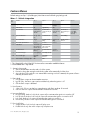
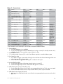
Feature Menus
Default settings are Opt. 1 (in bolder type). New features are bold with grey background.
Menu 1 - Vehicle integration
Menu
Item
Feature
Opt. 1
Opt. 2
Opt. 3
Opt.4
Opt. 5+
1
System Locking Mode
Active Locking
Passive Locking
Auto Relocking*
2
Panic Mode
On
Ign Off only
Off
3
Horn Function
Confirmation
Honk (20 ms)
& Panic
Confirmation
Honk (30 ms) &
Panic
Confirmation
Honk (40 ms)
& Panic
Confirmation
Honk (50 ms) &
Panic
Confirmation
Honk Off Panic Only
(Pulsed)
4
Ign-controlled locks
No Ign- locking
Lock & Unlock
Lock Only
Unlock Only
5
Door Lock Pulses
Single
Double Unlock
Only
Double Lock
Only
Double Lock &
Unlock
6
7
Door Lock output duration
0.8 sec.
3.5 sec.
0.4 sec.
2nd Unlock
2nd unlock on/
Ign-control after first unlock
2nd unlock on/
Ign-control with
first unlock
8
Comfort Closure
No Comfort
Closure
Comfort Closure
1
9
Hood Switch Type
Normally Open
Normally closed
10
Door Switch Type
Normally
Open
Normally
Closed
11
Remote Button unlock (Ign off)**
On
Off
Comfort
Closure 2
* The Green H2/6 or the Violet H2/12 wire must be connected to enable this feature.
** Not available with 1-way remote.
1. System Locking mode
1. Active: the transmitter must be used to lock the system
2. Passive Locking: after exiting the vehicle the system will automatically lock the doors
3. Auto re-locking: if the vehicle is not entered after receiving a unlock command, the system will automatically re-lock the doors
2. Panic Mode
1. On: the Panic output can be activated at any time
2. Ign Off Only : the Panic output can be activated only when the ignition is off
3. Off: the Panic output is defeated
3. Horn Duration
1. - Opt 4. 20 - 50 sec: sets the horn output duration with Panic mode at 30 seconds
2. Off: turns the horn output off and with Panic mode at 60 seconds
4. Ign-controlled Locks
1. No Ign-locking: the door lock/unlock outputs will not activate when ignition is turned on/off
2. Lock & Unlock: the door lock & unlock output will activate when ignition is turned on & off
3. Lock Only: the door lock output will activate when ignition is turned on
4. Unlock Only: the door unlock output will activate when ignition is turned off
5. Door Lock Pulses
1. Single: the door lock & unlock outputs will pulse once
2. Double Unlock only: the unlock output only will pulse twice
© 2011 Directed Electronics. All rights reserved.
11
3. Double Lock Only: the lock output only will pulse twice
4. Double Lock & Unlock: the lock & unlock outputs will pulse twice
6. Door Lock Output Duration
1. 0.8sec.: the door lock output pulses will be 800mS in duration
2. 3.5sec.: the door lock pulses will be 3.5 seconds in duration
3. 0.4 sec.: the door lock pulses will be 400mS in duration
7. Ignition Controlled 2nd Unlock
1. After first unlock: for Ign-controlled unlocking, the 2nd unlock will activate 800mS after the first (driver
door) unlock
2. With first unlock: for Ign-controlled unlocking, the 2nd unlock will activate at the same time as the first
(driver door) unlock
8. Comfort Closure
1. No comfort Closure: Comfort Closure is defeated when locking
2. Comfort Closure 1: the door lock pulse (or 2nd pulse for double pulses) will remain on for 20 seconds.
3. Comfort Closure 2: 800mS following the end of the door lock pulse (or 2nd pulse for double pulses);
the door lock output will turn on again for 20 seconds.
9. Hood Switch Type
1. Normally Open: for vehicles with a hood switch that rests at ground when the hood is OPEN
2. Normally Closed: for vehicles with a hood switch that rests at ground when the hood is CLOSED
10. Door Switch Type
1. Normally Open: for vehicles with door switches that rest at ground when the door is OPEN
2. Normally Closed: for vehicles with door switches that rest at ground when the door is CLOSED
11. Remote Button Unlock (Ign off)
1. On: a message telling the remote control to unlock the keypad is sent each time the vehicle ignition
is turned off
2. Off: no message is sent
12
© 2011 Directed Electronics. All rights reserved.
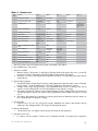
Menu 2 - Convenience
Menu
Item
1
Feature
Opt. 1
Opt. 2
One-time Bypass
No Bypass
Bypass
Opt. 3
Opt.4
Opt. 5+
3
4
5
2
Override Pulse Count
1
2
3
Door Open Error chirp*
On
Off
4
Ign-controlled Dome light
On
Off
5
OEM Alarm Disarm w/Aux/
trunk
On
Off
6
OEM Alarm Disarm Output
With Unlock
Before Unlock
7
OEM Alarm Disarm Pulses
1
2
8
Aux 1 Output type
Validity
Latch
Latch/reset/
ign
Timed
Off (5)/2nd
Unlock (6)
9
Aux 1 Linking
No Linking
Link to Lock
Link to Unlock
Link to Lock/
Unlock
Link to Remote
Start only
10
Aux 2 Output type
Validity
Latch
Latch reset/ign
Timed
Off (5)/2nd
unlock (6)
11
Aux 2 Linking
No Linking
Link to Lock
Link to Unlock
Link to Lock/
Unlock
Link to Remote
Start only
12
Aux 3 Output type
Validity
Latch
Latch reset/ign
Timed
Off (5)/2nd
unlock (6)
13
Aux 3 Linking
No Linking
Link to Lock
Link to Unlock
Link to Lock/
Unlock
Smart Key
Control (Link to
Remote Start
Off)*
14
Aux 4 Output Type
Validity
Latch
Latch reset/ign
Timed
Off (5)/2nd
Unlock (6)
15
Aux 4 Linking
No linking
Link to Lock
Link to Unlock
Link to Lock/
Unlock
Link to Remote
Start Only
16
Aux/Trunk Output type
Validity
Off
2nd unlock
Remote Start
Only
* The Green H2/6 or the Violet H2/12 wire must be connected to enable this feature.
1. One-time Bypass
1. Off: One-Time Bypass is not available
2. On: the One-Time Bypass feature will defeat Passive Locking once and, if Locked by remote control,
will defeat Comfort Closure and Aux outputs linked to Locking
2. Override Pulse Count
• 1-5: sets the number of presses (1-5) on the Control Button required to override the alarm system
3. Door Open Error chirp
1. On: if the door trigger is active when locking, the horn will emit a honk and a message will be sent
to the 2way remote control as an alert
2. Off: an active door trigger when locking will not create an alert output
4. Ign-controlled Dome light
1. On: the dome light output will activate when the ignition is turned off
2. Off: the dome light output will not activate when the ignition is turned off
5. OEM Alarm Disarm w/Aux/Trunk (H2/4 wire)
1. On: the OEM Alarm Disarm wire will pulse as programmed when the Aux/Trunk output is activated
2. Off: the OEM Alarm Disarm wire will not pulse when the Aux/Trunk output is activated
6. OEM Alarm Disarm Output (H2/4 wire)
1. With Unlock: the OEM Alarm Disarm wire will pulse as programmed at the same time as the unlock
(Blue) wire
© 2011 Directed Electronics. All rights reserved.
13
2. Before Unlock: the OEM Alarm Disarm wire will pulse as programmed before the unlock wire
3. Remote start only: the OEM Alarm Disarm wire will pulse as programmed during remote start only
7. OEM Alarm Disarm Pulses (H2/4 wire)
1. 1: the OEM Alarm Disarm wire will pulse once per operation
2. 2: the OEM Alarm Disarm wire will pulse twice per operation
8. Aux 1 Output Type (H2/4 wire)
1. Validity: when the Aux command is received the wire will turn on and remain on until the command
ceases
2. Latch: when the Aux command is received the wire will turn on and remain on until the command is
received again
3. Latch/reset/Ignition: when the Aux command is received the wire will turn on and remain on until the
command is received again or the ignition is turned on/off
4. Timed: when the Aux command is received the wire will turn on for the programmed time duration
(default 30sec)
5. Off: the output will not activate for a remote control command, use this option when the Aux command controls an external device such as a garage door module
6. 2nd unlock: the wire will operate as 2nd unlock and will not activate for remote control commands
9. Aux
1.
2.
3.
4.
5.
1 Linking
No Linking: the Aux output will not activate for a remote control command
Link to Lock: the Aux output will activate for the Lock command
Link to Unlock: the Aux output will activate for the Unlock command
Link to Lock/Unlock: the Aux output will activate for the Lock & Unlock commands
Link to Remote Start: the Aux output will activate for any Remote Start activation
10. Aux 2 Output Type
• Refer to Aux 1 Output Type descriptions
11. Aux 2 Linking
• Refer to Aux 1 Linking descriptions
12. Aux 3 Output Type
• Refer to Aux 1 Output Type descriptions
13. Aux 3 Linking
• Options 1-4: Refer to Aux 1 Linking descriptions
• Option 5: SmartKey Control (Link to Remote Start Off): The Aux output will pulse once following
Remote Start shut down for vehicles with push button engine stop operations. During runtime, if any
door is opened remote start will shut down immediately and pulse the output.
14. Aux 4 Output Type
• Refer to Aux 1 Output Type descriptions
15. Aux 4 Linking
• Refer to Aux 1 Linking descriptions
16. Aux/Trunk Output Type
• Refer to Aux 1 Output Type descriptions 14
© 2011 Directed Electronics. All rights reserved.
Menu 3 - Remote start
Menu
Item
Feature
Opt. 1
Opt. 2
Opt. 3
Opt.4
1
Transmission Mode
Manual*
Automatic
2
Engine Checking Mode
Virtual Tach
3
Cranking Time
0.6 sec.
Voltage
Off
Tachometer
0.8 sec.
1.0 sec.
1.2 sec.
1.4 (5)/ 1.6
(6)/ 1.8 (7)
2.0 (8)/ 4.0
(9)
60 min.
On- 10 min.
4
Remote Start Runtime
12 min.
24 min.
5
Activation Pulse Count
1
2
6
Turbo Mode
No Turbo Mode
On-1 min.
On-3 min.
On-5 min.
7
Timer Mode Runtime
12 min.
3 min.
6 min.
9 min.
8
Flex Relay Function
Ignition 2
Accessory 2
Starter 2
9
Diesel Start Delay
Wait-to Start
input
Timed 15 sec.
Timed 30 sec.
10
Accessory during Diesel Start
Delay
On
Off
11
Status 2 Output
Status
Latch Rear
Defogger
Pulse Rear
Defogger
12
Parking Light Output
Constant
Pulsed
Off
13
Anti-grind Output
On
Off
14
Tach Mode Starter Release
Normal
Increase
15
Vehicle Temp Auto Report**
Off
On
16
Remote Start Safelock
Off
On
Opt. 5+
Timed 45 sec.
Decrease
* The H1/6 Violet or the H1/8 Green wire must be connected for this feature.
** Not available with 1-way remote.
1. Transmission Mode
1. Manual: requires ‘Tachometer’ for the Engine Checking Mode, and requires the user to successfully
perform a procedure when parking the vehicle before remote starter will engage
2. Automatic: uses any of the Engine Checking Modes and does not require any special procedures
when parking
2. Engine Checking Mode
1. VirtualTach: battery voltage drop/rise during cranking determines when the starter output is released.
During runtime, constant voltage level is monitored to determine if the engine is running
2. Voltage: starter output during cranking is a programmed duration (Set in Cranking Time). During
runtime, constant voltage level is monitored to determine if the engine is running
3. Off: starter output during cranking is a programmed duration (Set in Cranking Time). The remote start
will keep the ignition/accessories active for the programmed runtime whether the engine is running
or not
4. Tachometer: tachometer input signal during cranking and runtime to determine when the starter output is released and if the engine is running.
3. Cranking Time
• 0.6/0.8/1.0/1.2/1.4/1.6/1.8/2.0/4.0 seconds: determines the starter output duration during
cranking for the ‘Voltage’ and the ‘Off’ Engine Checking Mode options
4. Remote Start Runtime
• 12/24/60 minutes: sets engine runtime during normal remote start operations
5. Activation Pulse Count
• 1/ 2 pulses: sets the number of remote control commands received or Activation Input required to
© 2011 Directed Electronics. All rights reserved.
15
activate and de-activate remote start
6. Turbo Mode
1. No turbo Mode: Turbo mode is not available
2. On – 1/3/5/10 minutes: Turbo Mode is available and, when activated, the engine will run for the
duration set per the selected option
7. Timer Mode Runtime
• 12/3/6/9 minutes: sets the runtime when the engine is started by the Timer Mode and SmartStart
features
8. Flex Relay Function
1. Ignition 2: the relay will emulate the Ignition 1 output during remote start
2. Accessory 2: the relay will emulate the Accessory 1 output during remote start
3. Starter 2: the relay will emulate the Starter output during remote start
9. Diesel Start Delay
1. Wait-to-start input: (-) input on the Grey/black (H2/20) WTS wire will delay the starter output until
the ground ceases.
2. Timed 15/30/45 seconds: delays the starter output per the selected option, the WTS wire does not
function.
10. Accessory during Diesel Start Delay
1. On: the Accessory outputs (H3/3 high current and H2/22 low current) will be ON during diesel
start delay
2. Off: the Accessory outputs (H/3 high current and H2/22 low current) will be OFF during diesel start
delay
11. Status 2 Output (Dark Blue H2/9 wire)
1. Status: the output will activate before the ignition outputs turn on, and de-activate after they turn off
during remote start
2. Latch rear defogger: the output activates 10 seconds after start if the interior temperature is below
55F. It turns off after 10 minutes or upon remote start off
3. Pulse rear defogger: the output activates (for 800mS) 10 seconds after start if the interior temperature
is below 55F.
12. Parking Light Output
1. Constant: the lights will turn on solid during remote start
2. Pulsed: the lights will pulse on/off during remote start
3. Off: the lights will be off during remote start
13. Anti-grind Output
1. On: the high current starter relay will be activated during remote start as anti-grind protection.
2. Off: the high current starter relay will not be activated during remote start, no anti-grind protection
is available.
14. Tach Mode Starter Release
1. Normal: the starter output will release normally during cranking (50% of the learned tachometer
value)
2. Increase: the starter output will release later during cranking (at 35% of the learned tachometer
value)
3. Decrease: the starter output will release sooner during cranking (at 35% of the learned tachometer
value)
15. Vehicle Temp Auto Report
1. Off: the report during remote start is defeated
2. On: the report is sent every 2 minutes during remote start if the temperature has changed (+/-) 1
degree since the last report
16
© 2011 Directed Electronics. All rights reserved.
16. Remote start Safelock
1. Off: the Door lock and Factory Alarm Re-arm outputs will maintain the current status (locked/unlocked) during remote start and after shut down
2. On: the Door lock and Factory Alarm Re-arm outputs will arm/lock the vehicle during remote start
and after shutdown
Bitwriter - Only Options
If programming with the Bitwriter®, the learn routine can be locked or unlocked. If the learn routine
has previously been locked, it must be unlocked with Bitwriter® - this cannot be done manually with
the Control button.
The Bitwriter®
gives you access to a wider range of system options. These features and the adjustments
that may be programmed are described in the table below.
Menu
Item
Feature
Default
Opt. 2
Opt. 3
Opt.4
Opt. 5+
1
Aux/Trunk Icon Type*
Trunk
Window
Sunroof
Audio
Lights/Left dr/Right dr/Rear Hatch
2
Aux 1 Timed Output
30 sec.
Options: 1 to 90 sec.
3
Aux 1 Icon Type*
Pulsed
Trunk
Sunroof
Audio/Lights/Left dr/Right dr/Rear Hatch/
Timed/Latched
4
Aux 2 Timed Output
30 sec.
Options: 1 to 90 sec.
5
Aux 2 Icon Type*
Pulsed
Trunk
Sunroof
Audio/Lights/Left dr/Right dr/Rear Hatch/
Timed/Latched
6
Aux 3 Timed Output
30 sec.
Options: 1 to 90 sec.
7
Aux 3 Icon Type*
Pulsed
Trunk
Sunroof
Audio/Lights/Left dr/Right dr/Rear Hatch/
Timed/Latched
8
Aux 4 Timed Output
30 sec.
Options: 1 to 90 sec.
9
Diesel Start Delay
type (seconds)
15 sec.
Options: 1 to 90 sec.
10
Timer Mode Runtime
(minutes)
12 min.
Options: 1 to 16 min.
11
Timer Mode Starts
6 starts
Options: 1/2/3/4 to 24 (Starts) in increments of 2
12
Timer mode intervals
(hours)
3 hr.
Options: 1/2/3/4 to 24 in 2 hour increments
13
Smart start low temp
0° (F)
Options: OFF, -20° to 70° in 10° increments
14
Smart start high temp
100° (F)
Options: OFF, 40° to 130° in 10° increments
15
Smart start low battery (volts)
10.5V
Options: OFF, 9V to 12.5V in 0.5V increments
16
Starter Release Fine
Tune
6
(normal)
Options: 0 to 20 in increments of 1
17
Feature Programming
Unlocked
Locked
18
Transmitter Programming
Unlocked
Locked
19
Remote Start Runtime
12 min.
Options: 1 to 60 min.
20
Virtual Tach Fine Tune
Not Initialized
Options: Not initialized, 0 to 1000 in 50 millisecond increments
Window
Window
Window
* Available only on remotes with display screens
© 2011 Directed Electronics. All rights reserved.
17
1. Aux/Trunk Icon Type: sets the name to be displayed in the Text Field when the Aux/Trunk output is activated/de-activated
2. Aux 1 Timed Output: sets the output duration in 1 second intervals up to 90 seconds for Aux 1
3. Aux 1 Icon Type: sets the name to be displayed in the Text Field when the Aux 1 output is activated/
de-activated
4. Aux 2 Timed Output: sets the Aux 2 “Timed” output in 1 second intervals up to 90 seconds
5. Aux 2 Icon Type: sets the name to be displayed in the Text Field when the Aux 2 output is activated/
de-activated
6. Aux 3 Timed Output: sets the Aux 3 “Timed” output in 1 second intervals up to 90 seconds
7. Aux 3 Icon Type: sets the name to be displayed in the Text Field when the Aux 3 output is activated/
de-activated
8. Aux 4 Timed Output: sets the Aux 4 “Timed” output in 1 second intervals up to 90 seconds
9. Diesel Start Delay Timer: sets the delay before engine crank in 1 second intervals up to 90 seconds for
diesel engine vehicles
10.Timer Mode Runtime: sets the duration of runtime when the engine is started by the Timer Mode and Smart
Start features
11.Timer mode Starts: sets the number of times the engine will be started by the Timer Mode and Smart Start
features
12.Timer mode Intervals: sets the number of hours between engine starts by the Timer Mode and Smart Start
features
13.Smart Start Low Temperature: sets the low temperature threshold required for Smart Start to start the
engine
14.Smart Start High Temperature: sets the high temperature threshold required for Smart Start to start the
engine
15.Smart Start Low battery (Volts): sets the low battery level threshold required for Smart Start to start the
engine
16.Starter Release Fine Tune: adds or subtracts crank time in Tachometer mode in order to overcome engine
types that short crank or over-crank on the first start attempt
17.Feature Programming: locks and unlocks the user’s ability to enter the feature menus and manually
change the main unit programming using the Control Center
18.Transmitter Programming: locks and unlocks the user’s ability to enter the remote control/Reset menu and
manually change any functions using the Control Center
19.Remote Start Runtime: sets the duration of runtime when the engine is started by remote command
20.VirtualTach Fine tune: adds or subtracts crank time in VirtualTach mode in order to overcome engine types
that short crank or over-crank on the first start attempt
18
© 2011 Directed Electronics. All rights reserved.
Basic Remote Functions
See Owner’s guide for functionality details on the 1-way remote controls.
Reset and Deletion
If a feature/virtual tach needs to be reset or the remote controls need to be deleted, use the following procedure.
1. Turn the ignition to the ON position (The heavy gauge pink wire must be connected).
2. Within 10 seconds, press and release the Control button: 2 times if you want to delete remotes, 3 times
to reset features or 4 times to reset virtual tach. These function steps are described next.
Step 2:
Delete remotes: This feature erases all remotes from the memory of the keyless entry system. This is
useful in cases when a customer’s remote is lost or stolen.
Note: This does not reset the programmed features of the keyless entry system or reset the Virtual
Tach setting.
Step 3:
Reset Features: This resets all features of the keyless entry system to the factory default settings.
Note: This feature does not delete the remotes from the keyless entry system or reset the Virtual Tach
setting
Step 4:
Virtual Tach Reset: Deletes all previously learned values for Virtual Tach, and on the next remote start
sequence the unit begins virtual tach initialization.
Note: The “Zap” feature on the Bitwriter does not reset the Virtual tach setting.
3. Once you have selected the function step, press the Control button once more and hold it. The LED flashes
and the horn honks to confirm the selected functional step. Do not release the Control button
button on the remote control. The unit honks to confirm that
4. While holding the control button, press the
the feature has been successfully reset.
AUX
Once the feature is reset, the Control button can be released.
© 2011 Directed Electronics. All rights reserved.
19
Troubleshooting: Keyless Entry
System does not Auto re-lock:
1. Is Auto re-locking programmed ON?
2. Are the door inputs connected? Either the H2/6 green or the H2/12 Violet should be connected.
Door locks operate backwards.
• This unit has easily-reversed lock/unlock outputs. Recheck wire connections to see if you have reversed these.
Troubleshooting: Remote Start
The remote will not activate the remote start
1. Check remote startup diagnostics.
2. Is the neutral safety switch plugged in and turned on?
3. If the vehicle has an automatic transmission, make sure the remote start is programmed for Automatic
Transmission mode.
4. Is the remote programmed to the system?
5. Can the remote start be activated manually by applying a ground pulse to the H2/21 White/Blue
wire?
6. Check the harnesses and their connections. Make sure that the harnesses are completely plugged into
the remote start module. Make sure there are good connections to the vehicle wiring.
7. Check voltage and fuses on the main 6-pin harness and on the heavy gauge remote start harness.
The remote start will activate, but the starter never engages.
1. Check for voltage on the purple starter wire two seconds after the remote start becomes active. If
there is voltage present, skip to Step 8. If there is not voltage present, advance to Step 2.
2. Check the 30A fuses.
3. If the gray/black wait-to-start wire is detecting ground upon activation, the starter will not crank.
4. Is the tach wire connected? If so disconnect it and remote start the vehicle to see if the purple wire
sends out voltage. If you get voltage you will need to go to an alternate tach source, the tach wire
you are currently on has a voltage spike upon ignition power up which can cause the remote start to
not send out the crank voltage.
5. Is the vehicle a Chrysler or GM with a multiplexed starter wire? The vehicle will not crank if the resistance is incorrect on the multiplexed accessory/starter wire.
6. Is the vehicle a GM? If so the Brown 2nd accessory needs to be powered up on some of the vehicles
for the vehicle to crank.
7. If this is a manual transmission vehicle, the clutch will need to be bypassed (see tech tip # 10000 at
www.directechs.com)
8. Make sure the purple starter wire is connected on the starter side of the optional starter kill/anti-grind
relay.
9. Does the vehicle have an immobilizer? Some immobilizer systems will not allow the vehicle to crank
if active.
10.Check connections. The heavy gauge remote start input wires on the heavy gauge 10-pin connector
should have a solid connection. “T-taps” or “scotch locks”.
The vehicle starts, but immediately dies.
1. Does the vehicle have an immobilizer? The vehicle’s immobilizer can cut the fuel and/or spark during
unauthorized starting attempts.
2. Is the remote start programmed for virtual tach or voltage sense? If so, the crank time may not be set
high enough. Voltage sense will not work on some vehicles.
3. Is the remote start in tach mode? If so has the tach been programmed to the system?
4. Check diagnostics. Sometimes a shutdown will become active during cranking or just after cranking.
The vehicle starts, but the starter keeps running.
1. Is the system programmed for engine checking off or virtual tach voltage sense? When programmed
for either of these features, the engine cranks for the pre programmed crank time regardless of how
20
© 2011 Directed Electronics. All rights reserved.
long it takes for the vehicle to actually start. Adjust to a lower cranking time.
2. Was the Tach Learn successful? The LED must light solid and bright to indicate a successful learn.
3. Make sure that there is a tach signal at the purple/white tach input wire of the remote start. If there
is not a tach signal, recheck the connection to the vehicle’s tach wire and make sure the wire is not
broken or shorted to ground leading to the remote start.
4. Is an ignition or accessory output wire connected to the starter wire of the vehicle? Verify the color
of the starter wire in the vehicle and confirm that an ignition or an accessory output is not connected
to that wire.
The vehicle starts, but will only run for 10 seconds
1. Is the remote start programmed for voltage sense? If this does not work, a tach wire should be
used.
2. Check shutdown diagnostics.
The climate control system does not work while the unit is operating the vehicle.
1. Either the wrong accessory wire is being energized or more than one ignition or accessory wire must
be energized in order to operate the climate control system.
2. If the vehicle has an electronic climate control system some will reset when the key is turned off and
then back on, unfortunately this is a function of the vehicle and cannot be bypassed.
MTS - Manual Transmission Start diagnostics
When enabling MTS, if you get a failure notification from the remote or the vehicle fails to remain started
check for following:
• Tachometer not connected or programmed.
• E-brake not connected to the remote start unit. The black/white H2/12 neutral safety wire must have
a ground when the parking brake is set.
• Foot must be off the brake when activating the MTS mode on the remote.
• Is the door open when enabling the MTS mode? If so this would cause the unit to enter Pit Stop Mode
and the remote start will continue to run when arming/locking the system.
• Is the door input connected? The system needs to see a door open then close after initiating the remote start.
• Does the vehicle have a delayed dome light? If you are connected to the dome light wire and the
dome light is staying on after arming/locking the system, the system can exit the MTS mode.
• Make sure the neutral safety switch is plugged in and turned on.
MTS mode exiting diagnostics:
If the remote start has entered the MTS mode but exits the mode after the system is armed/locked. Check
these for possible causes.
• The vehicle door has been opened in your absence.
• Does the vehicle have a delayed dome light circuit or does the dome light come on when the ignition
is shut off? If so you may need to go to the independent door inputs of the vehicle.
• If you are connected to the dome light wire in the vehicle and cannot connect the system to the
individual door inputs of the vehicle due to it having normally closed door inputs, you can use the
Xpresskit DTIMAZDA module or Tech Tip # 1921 at www.directechs.com to interface with these
types of circuits.
• The E-brake wire connected to the neutral safety input of the system loses ground when ignition
is turned off or after a certain amount of time, with these vehicles unfortunately there is no workaround.
• The E-brake wire connected to the neutral safety input of the system has a poor ground. Clean the
contacts on the switch or replace the switch.
© 2011 Directed Electronics. All rights reserved.
21
Status LED
LED
Quick Reference Install Guide
Remote Start w/ Keyless Entry
1-Way Super Code
Wiring Connections
Installation Points
Guide Translations
For a Spanish or French version of the Installation Guide, please download it from
Control Center
www.directechs.com under Resources.
Valet switch
Estimado Cliente:
Si buscas los guías de instalación, por favor de bajar lo del Resources en el sitio
www.directechs.com
LED
H/1
RED
(+)12VDC CONSTANT INPUT
BLACK
(-) CHASSIS GROUND
H/3
BROWN
(-) 200mA HORN HONK OUTPUT
H/4
WHITE/BROWN
LIGHT FLASH ISOLATION WIRE - PIN 87a light flash relay
H/5
WHITE
PIN 30 of LIGHT FLASH RELAY
H/6
ORANGE
500 mA GROUND WHEN ARMED OUTPUT
Door Lock, 3-pin connector
H/3
ORANGE
(+) ACCESSORY OUTPUT
H/4
VIOLET
(+) STARTER OUTPUT
H/5
RED
(+) 12VDC CONSTANT INPUT for ignition 1 relay
BLUE
500mA (-) UNLOCK OUTPUT
H/6
PINK/WHITE
(+) IGNITION 2 / FLEX RELAY OUTPUT
2
EMPTY
NOT USED
H/7
PINK/BLACK
(+) FLEX RELAY INPUT 87A key side (if required) of FLEX RELAY
3
GREEN
500mA (-) LOCK OUTPUT
H/8
RED/BLACK
(+) 12VDC CONSTANT INPUT for ACC and starter relays
LIGHT FLASH POLARITY
(10A (MAXIMUM) FUSE JUMPER)
Bitwriter/SmartStart Port
10A FUSE
MINI ATM
RPN: 8540
Thermistor/Temp Sensor
+
Remote Start
8-pin Harness
-
4x04
IMPORTANT! Neutral Safety
switch must be plugged in
and in the ON position
PINK/WHITE
1 3 5
BLACK/WHITE
2 4 6
24 GREEN/WHITE
INSERTION/WIRE SIDE
ON
Neutral Safety
Switch
23 VIOLET/WHITE
RF Port
for IVU
Main 6-pin
Harness
Auxiliary/Shutdown Harness 24-pin connector
Door Lock
Port
Horn Input
Polarity Jumper
Control Center
D2D Port (for external
Xpresskit interface module)
Aux/Shutdown/Trigger 24-pin Harness
H/1
PNK/WHITE
(-) 200mA FLEX RELAY CONTROL OUTPUT
16
BROWN
(+) BRAKE SHUTDOWN INPUT
H/2
BLACK/WHITE
(-) NEUTRAL SAFETY INPUT
17
GRAY
(-) HOOD PIN INPUT (NC OR NO)
H/3
BLUE/WHITE
(-) 200mA 2ND STATUS /REAR DEFOGGER OUTPUT
18
VIOLET/YELLOW
(-) 200mA STARTER OUTPUT
H/4
GREEN/BLACK
(-) 200mA FACTORY ALARM DISARM OUTPUT
19
BLUE*
FACTORY HORN INPUT (Use Jumper to set polarity)
(-) 200mA TRUNK RELEASE OUTPUT
20
GRAY/BLACK
(-) DIESEL WAIT TO START INPUT
WHITE/BLUE
ACTIVATION INPUT
H/6
GREEN
(-) DOOR INPUT
21
H/7
BLACK/YELLOW
(-) 200mA DOME LIGHT OUTPUT
22
ORANGE
(-) 200mA ACCESSORY OUTPUT
H/8
EMPTY
------------------------------------
23
VIOLET/WHITE
TACHOMETER INPUT
24
GREEN/WHITE
(-) 200mA FACTORY ALARM ARM OUTPUT
H/9
DARK BLUE
(-) 200mA STATUS OUTPUT
H/10
PINK
(-) 200mA IGNITION 1 OUTPUT
H/11
WHITE/BLACK
(-) 200mA AUX 3 OUTPUT
H/12
VIOLET
(+) DOOR INPUT
13
WHITE/VIOLET
(-) 200mA AUX 1 OUTPUT
14
VIOLET/BLACK
(-) 200mA AUX 2 OUTPUT
15
ORANGE/BLACK
(-) 200mA AUX 4 OUTPUT
*This optional input can be connected to the horn circuit (+ or -). When this wire
receives input for a minimum of .5 seconds, the system reports a trigger on the
2-way remote. This is useful on vehicles that have a factory security system that
can be armed/disarmed with the Directed system. This system will not report that
a zone has been triggered when unlocking with the 2-way remote. This feature is
not available on the 1-way remote.
Timer mode error: Ignition is on or shutdown input is active when activating
timer mode.
Turbo mode error: Turbo mode is programmed off, engine is not on or shutdown input is active.
Manual mode error: MTS mode not enabled.
Status LED
Learning Virtual Tach (not needed with hardwire tach inputs)
1
© 2011 Directed Electronics. All rights Reserved.
Control button
Learning the Tach (not needed with Virtual Tach)
H/2
RED/WHITE
*
Cher consommateur:
Si vous désirez une version française ou espagnole du guide d’installation, veuillez
Control Center
s.v.p. le télécharger à l’adresse suivante: www.directechs.com en appuyant sur Control Center
To learn the tach signal:
l’icône <<Resources>>.
1. Start the vehicle with the key.
2. Within 5 seconds, press and hold the Control button.
Remote Start, 8-pin connector
3. After 3 seconds the status LED on your Control Center lights constant when
PINK
(+) IGNITION 1 INPUT/OUTPUT
H/1
the tach signal is learned.
RED/WHITE
(+) 12VDC CONSTANT INPUT for ignition 2 and flex relays
H/2
4. Release the Control button.
Main Harness, 6-pin connector
H/5
Control Center
To program Virtual Tach:
1. After the install is complete, remote start the engine. The programming operation may require 3 cranks of the starter before the engine starts and runs.
Do not turn off the remote start if this happens, it is a normal programming
operation.
2. Once the engine begins running, let it run for at least 30 seconds.
3. Using the Remote, send the Remote start command to turn remote start off.
Virtual Tach is programmed.
To reset Virtual Tach, go into the Remote Pairing section of this guide and press/release the Control button 4 times for step #4, then press and hold the Control button
to reset Virtual Tach. Virtual Tach cannot be reset with the Bitwriter.
Note: Virtual Tach cannot be used in MTS Manual Transmission Mode. It is also not
recommended for diesel trucks.
Virtual Tach handles disengaging the starter motor during remote starting – it does
not address over-rev. If the customer wants to have the over-rev protection capability,
the tach wire must be connected.
Important: After successfully learning Virtual Tach, a small minority of vehicle starters may over crank or under crank during remote start. The
Bitwriter can be used to fine tune the starter output time in 50mS increments
to compensate for such an occurrence.
Startup Diagnostics: If the vehicle fails to activate the remote start, the remote start
module will flash the parking lights on the vehicle to notify you of what caused the
no-start situation.
Parking Light Flashes
5 flashes Brake wire is active
6 flashes Hood pin wire is active
7 flashes Manual transmission mode is enabled and not initialized.
8 flashes Neutral safety wire has no ground or the neutral safety switch is Off.
Remote Pairing
Prepare the vehicle system to be Paired with a new remote
1. Turn the key to the ON position.
2. Within 5 seconds press and release the Control button on the system’s Control
Center one time.
3. Within 5 seconds, press and hold the Control button on the Control Center.
The status LED will flash one time and the horn honks to confirm the vehicle is
ready for remote pairing.
4. Release the Control button and proceed below.
Note: If no remote pairing results, the system will exit after 60 seconds.
Prepare the new remote to be Paired with the system
Remote Pair matches your remote to the system. Make sure the remote is set for the
desired Car 1 (Default) or Car 2 operation for the system it will be paired with.
AUX
AUX
Press and hold the button for 8 seconds.
Wait for the Transmit LED to light solid. Release the button. Press the
for 1 second. The transmit LED will blink 3 times.
Within 5 seconds, press the
button.
The vehicle horn will honk. You have now successfully learned the remote to the
vehicle remote start system.
Press the
button two times to exit learn routine on the remote. The transmit
LED will turn off and exit.
1.
2.
3.
4.
5.
AUX
6.
AUX
To perform shutdown diagnostics:
1. With the ignition Off, press and hold the Control button.
2. Turn the ignition On and then back Off while holding the Control button.
3. Release the Control button.
4. Press and release the Control button. The status LED flashes to report the last
shutdown for one minute or until the ignition is turned on, as shown in the
following table:
Button
Shutdown Mode
Runtime expired
Over-rev shutdown
Low or no RPM
Transmitter shutdown (or optional push button)
(+) Brake shutdown
(-) Hood shutdown
Timer mode/Turbo mode/Manual mode error *
Neutral safety shutdown
Low battery (voltage mode)
Wait-to-start input timed out
DIRECT
ACCESS
X1
AUX
X2
AUX
X3
X4
LOCK
SILENT LOCK
UNLOCK
SILENT UNLOCK
REMOTE VALET
CAR FINDER
REMOTE START
RUNTIME RESET
TIMER MODE
SMART START
REAR DEFOGGER
TRUNK RELEASE
AUX 1
AUX 2
AUX 3
AUX 4
AUX
AUX
AUX
UX
AA U
X
Status LED Flashes
1 flash
2 flashes
3 flashes
4 flashes
5 flashes
6 flashes
7 flashes
8 flashes
9 flashes
11 flashes
AUX
Basic Remote Functions
Level
Remote Start Shutdown/Startup Diagnostics
AUX
AUX
FUNCTION SHIFT
Bitwriters with a date code of 6a or older require an IC
upgrade (p/n 998M). Some bitwriters with a date code
of 6B do not require the IC upgrade, refer to tech tip #
1112 for more information.
The Bitwriter® (p/n 998U)
requires chip version 2.7 or
newer to program this unit.
1
Programming System Features
Feature Menus
The System Features Learn Routine dictates how the unit operates. It is possible to
access and change most of the feature settings using the Control button.
Turn the ignition on, then off.
Select a Menu. Press and hold the Control button. The number of horn honks
and LED flashes indicates the menu number. 1 horn honk and LED flash
indicates menu 1, 2 horn honks and LED flashes - menu 2 and 3 horn honks
and LED flashes for menu 3.
When the desired menu horn honks are heard with LED flashes, release the
Control button.
Select a Feature. Press and release the Control button the number of times
corresponding to the feature you wish to change. Then press and hold one
more time to select the features.
Program the Feature. While holding the Control button, you can program the
feature using the remote control.
1.
2.
3.
4.
5.
For features with only two options;
= option 1 while
= option 2.
For features with more than two options;
selects the options in ascending order,
while
selects them in descending order.
AUX
Default settings are in bold type. New features are bold in solid grey rows.
Menu 1 - Vehicle Integration
Menu
Item
One-time Bypass
No Bypass
Bypass
2
Valet Switch Pulse
Count
1
2
Opt.4
3
4
Opt. 5+
5
Menu
Item
Feature
Opt. 1
Opt. 2
Opt. 3
Opt.4
1
Transmission Mode
Manual
Automatic
2
Engine Checking Mode
Virtual
Tach
Voltage
Off
Tachometer
3
Cranking Time
0.6 sec.
0.8 sec.
1.0 sec.
1.2 sec.
1.4 (5) /1.6
(6)/ 1.8 (7)/
2.0 (8)/
4.0(9)
4
Remote Start Runtime
12 min.
24 min.
60 min.
5
Activation Pulse Count
1
2
6
Turbo Mode
No Turbo
Mode
On-1 min.
On-3 min.
On-5 min.
On-10 min.
9 min.
3
Door Ajar Error msg
On
Off
System Locking Mode
Active
Locking
Passive
Locking
Auto Relocking
4
Ign-controlled Dome
light
On
Off
2
Panic Mode
On
Ign Off
only
Off
5
OEM Alarm Disarm
w/Aux/trunk
On
Off
3
Horn Function
Confirmation
Chirp (20
ms) & Panic
Confirmation Chirp
(30 ms) &
Panic
Confirmation Chirp
(40 ms) &
Panic
6
OEM Alarm Disarm
Output
With
Unlock
Before
Unlock
7
OEM Alarm Disarm
Pulses
1
2
7
Timer Mode Runtime
12 min.
3 min.
6 min.
8
Aux 1 Output type
Validity
Latch
Latch/
reset/ign
Timed
Off (5)/2nd
Unlock (6)
8
Flex Relay Function
Ignition 2
Accessory 2
Starter 2
Aux 1 Linking
No Linking
Link to Lock
Link to
Unlock
Link to
Lock/
Unlock
Link to
Remote Start
only
9
Diesel Start Delay
Wait-to
Start input
Timed 15
sec.
Timed 30
sec.
10
Accessory during Diesel
Start Delay
On
Off
11
Status 2 Output
Status
Latch Rear
Defogger
Pulse Rear
Defogger
12
Parking Light Output
Constant
Pulsed
Off
13
Anti-grind Output
On
Off
14
Tach Mode Starter
Release
Normal
Increase
15
Vehicle temp
auto report*
Off
On
16
Remote Start Safelock
Off
On
Confirmation
Chirp Off
- Panic
Only
(Pulsed)
Remote
Start Only
4
Ign-controlled locks
No Ignlocking
Lock &
Unlock
Lock Only
Unlock
Only
9
5
Door Lock Pulses
Single
Double
Unlock
Only
Double
Lock Only
Double
Lock &
Unlock
10
Aux 2 Output type
Validity
Latch
Latch
reset/ign
Timed
Off (5)/2nd
unlock (6)
0.4 sec.
11
Aux 2 Linking
No Linking
Link to Lock
Link to
Unlock
Link to
Lock/
Unlock
Link to
Remote Start
only
12
Aux 3 Output type
Validity
Latch
Latch
reset/ign
Timed
Off (5)/2nd
unlock (6)
13
Aux 3 Linking
No Linking
Link to Lock
Link to
Unlock
Link to
Lock/
Unlock
Smart Key
Control (Link
to Remote
Start Off)
6
Door Lock output
duration
0.8 sec.
3.5 sec.
7
2nd Unlock
2nd unlock
on/ Igncontrol after
first unlock
2nd unlock
on/ Igncontrol with
first unlock
8
Comfort Closure
No Comfort
Closure
Comfort
Closure 1
9
Hood Trigger Type
Normally
Open
Normally
closed
14
Aux 4 Output Type
Validity
Latch
Timed
Normally
open
Normally
closed
Latch
reset/ign
Off (5)/2nd
Unlock (6)
15
Aux 4 Linking
No linking
Link to Lock
Ignition Off msg
(remote button
unlock)
On
Off
Link to
Unlock
Link to
Lock/
Unlock
Link to
Remote Start
Only
16
Aux/Trunk Output type
Validity
Off
2nd unlock
Feature
Default
Opt. 2
Opt. 3
Opt.4
Opt. 5+
Aux 1 Icon Type*
Pulsed
Trunk
Window
Sunroof
Audio/Lights/Left dr/
Right dr/Rear Hatch/
Timed/Latched
10
To select another menu:
1. Press and hold the Control button.
2. After 3 seconds, the unit advances to the next menu and the horn honks and
the LED flashes, indicating which menu has been accessed.
1
Opt. 3
1
button resets the feature to the factory default.
To access another feature in the same menu:
1. Press and release the Control button the number of times necessary to advance
from the feature you just programmed to the next one you want to program.
2. Then press the Control button once more and hold it.
Opt. 2
Opt. 3
AUX
Once a feature is programmed:
• Other features can be programmed within the same menu
• Another menu can be selected
• The learn routine can be exited if programming is complete
Opt. 1
Opt. 2
Confirmation Chirp
(50 ms) &
Panic
Opt. 5+
Menu 3 - Remote start
Feature
Opt. 1
AUX
Note: Pressing
Opt.4
Menu
Item
Feature
AUX
AUX
Menu 2 - Convenience
11
Door Switch Type
Comfort
Closure 2
Opt. 5+
Timed 45
sec.
Decrease
* not applicable to 1way remote
The learn routine exits if any of the following occurs:
• The ignition is turned On
• There is no activity for 30 seconds
• The Control button is pressed too many times
Bitwriter - only Options
If programming with the Bitwriter®, the learn routine can be locked or unlocked. If the learn routine has previously been locked, it must be unlocked
with Bitwriter® - this cannot be done manually with the Control button.
gives you access to a wider range of system options. These
The Bitwriter®
features and the adjustments that may be programmed are described in the table
below. Default settings are in bold.
Menu
Item
1
2
Feature
Aux/Trunk Icon Type*
Aux 1 Timed Output
Default
Trunk
30 sec.
Opt. 2
Window
Opt. 3
Sunroof
Options: 1 to 90 sec.
Opt.4
Audio
Opt. 5+
Lights/Left dr/Right
dr/Rear Hatch
Menu
Item
3
4
Aux 2 Timed Output
30 sec.
Options: 1 to 90 sec.
5
Aux 2 Icon Type*
Pulsed
Trunk
6
Aux 3 Timed Output
30 sec.
Options: 1 to 90 sec.
7
Aux 3 Icon Type *
Pulsed
Trunk
Window
Window
8
Aux 4 Timed Output
30 sec.
Options: 1 to 90 sec.
9
Diesel Start Delay
type (seconds)
15 sec.
Options: 1 to 90 sec.
Sunroof
Sunroof
Audio/Lights/Left dr/
Right dr/Rear Hatch/
Timed/Latched
Audio/Lights/Left dr/
Right dr/Rear Hatch/
Timed/Latched
Menu
Item
Feature
Default
Opt. 2
Timer Mode Runtime
(minutes)
12 min.
Options: 1 to 16 min.
11
Timer Mode Starts
6 starts
Options: 1/2/3/4 to 24 (Starts) in increments of 2
12
Timer mode intervals
(hours)
3 hr.
Options: 1/2/3/4 to 24 in 2 hour increments
13
Smart start low temp
0° (F)
Options: OFF, -20° to 70° in 10° increments
14
Smart start high temp
100° (F)
Options: OFF, 40° to 130° in 10° increments
15
Smart start low battery (volts)
10.5V
Options: OFF, 9V to 12.5V in 0.5V increments
16
Starter Release
Fine Tune
6
(normal)
Options: 0 to 20 in increments of 1
17
Feature Programming
Unlocked
Locked
10
Opt. 3
Opt.4
Opt. 5+
Menu
Item
Feature
Default
Opt. 2
Transmitter Programming
Unlocked
Locked
19
Remote Start Runtime
12 min.
Options: 1 to 60 min.
20
Virtual Tach Fine
Tune
Not Initialized
Options: Not initialized, 0 to 1000 in 50 millisecond
increments
18
Opt. 3
Opt.4
Opt. 5+
Directed Logo Usage
*available on remotes with display screens
only
Logo, Directed with designed in USA.eps
See full Installation Guide for more
detailed information on this system.
Such information and more can be
found online at:
www.directechs.com
Logo, Directed Electronics w-driven.eps
QRN4104 2011-09
© 2011 Directed Electronics. All rights Reserved.
2
~
VEHICLE EQUIPPED WITH A DEl ® REMOTE START SYSTEM
If vehicle battery is disconnected, the system may attempt to start when the battery is reconnected or transmitter
is used. Press brake to disengage. Check with vehicle owner to determine if hood pin switch or override switch
was installed to disengage the system for service.
-
..IMPORTANT SAFETY NOTICE
Z'Ucrem L®PRODU CT REGIST RATION
E L E C T R 0 N I C S, I N C.
Security
Protect Yot1r Investment
Register your product for:
~Recall Notifications
We contact our customers in case of recall.
~ Owner Verification
Registration can serve as verification of your ownership in the event of product theft or loss.
~ Efficient Service
Completing this card will help you obtain more efficient warranty service in case there
is a problem with your product.
Don't forget
We know you are busy, but registering is important, quick and easy!
Or register online at www.prodregister.com/directed
Please send products and
other correspondence to:
First-Class
Postage
Required
Post Office will
not deliver
without proper
postage.
Directed Electronics Inc.
1 Viper Way
Vista, CA 92081
X F J 01
E l E C T R 0 N I C S, I N C.
PO BOX 174391
DENVER CO 80217-4391
II. I. II.
I
I I I I
I. I. Ill. I. 1.. I. II. I. I.
I I
I I
I
I I I I
Ill. I.
I I I I
II. I. I. I
IMPORTANT!
1.
1. 0 Mr.
2. 0 Mrs.
IMPORTANT!
Please complete and return within the next 10 days
or register online at www.prodregister.com/directed
E l E C T R 0 N I C S, I N C.
4. I~ Miss
3. lJ Ms.
First name
Initial
X F J 01
Last name
Street
Apt.
City
State/Province
Zip/Postal code
E-mail address
I
2.
Your date ol birth:
3.
Marital status: 1. C: Mamerl
4.
Date ot purchase:
Mofl/h
I
Month
Whal benefits most influenced your dacision to purchase
this product? (chec!< up to three)
01. 0 Improved security
11. [l Warranty
02. 0 Improved convenience 12. :.J PriceNalue
03. [] Improved performance 13. 0 Rebate/Promotion
04. [] Compatibility with
14. [] Immediate
vehicle
availability
05. [J Ease of <nslallallon
15. 0 Friend/Relative's
06 [] Style/Design/Color
recommendation
07. [J Special features
16.
Salesperson's
08. 0 Quality/Durability
recommendation
09. =J Increase vehicle value 17.
Dealer proximity
10
Funcl<onality
14.
What other brands did you seriously consider before making
this purchase?
1. U No other brands
5
Auto Page
considered
6.
Compustar
2. :__] Other Directed
7. .J Prestige
Electronics brands
8.
Pursuit
3.
Code Alarm
9. L- i Crime Stopper
4.
Audiovox
10. l ' Bulldog
15.
No/including yourself, what is the GENDER and AGE (in years)
of children and other adutts living in your household?
1. r - 1 No one else in household
2. r I Chi ld under 1 year
Year
2.
1
Single
I
Year
Day
5.
Model number:
6.
Name of store where purchased:
7.
Price paid (excluding sales tax):
8.
Which Directed Electronics brand did you purchase?
1
Autostart
4 J Python
2.
Avital
5. • 1 Viper
3.
Cliflord
9.
What type ol product did you purchase?
1.
Security system
10.
13.
$
.00
2
Security system with remote start
4.
Remote start system
Keyless entry system
Male Female
1.
cJ
Age
2.
yrs.
In what vehicle will this product be used?
1.
Car
2.
~
Truck
3.
J
suv
4.
Van
5. '::::J Minivan
1
6.
Motorcycle
7. iJ Boat
8.
Motor home
9. :::J Other
1
16.
Make of vehicle:
Model name:
YIN 1:
Year:
A. [_] Bought new
[~ Bought used
C.
leased
0 L Leased used
How did
01.
02.
C3
04.
05
06
12.
Male Female
yrs
Vehicle type:
11.
Age
··1
you firs! become aware of this
Local newspaper
07. ~J
Yellow pages
08. U
Magazine
advertisement
09. LJ
TV commercial
Magazine article/
10. ' J
revtew
Friend/Relative's
11. [ J
recommendation
12 lJ
product? {chec!< one)
Radio commercial
Salesperson's
recommendation
Manufacturer's
website
Retailer's
website
Internet forum
Other
What factors most influenced the purchase? (chec!< up to three)
01 ;:::: Directed Electronics 10.
Rebate/Promotion
reputation
11. ~ Style/Design/Color
02.
Brand reputation
12. LJ Dealer proxim ity
03.
Experience with
13, 0 FriendfRelative's
Directed product
recommendation
04. 0 Experience with dealer 14 :::J Salesperson's
05.
Value/Price
recommendation
06. I' Warranty
15. 0 Ease of mstallation
07. :J Special features
16. 0 Compatibility with
08. Ll Quality/Durability
vehicle
09. :J Sound board/In-vehicle 17. 0 Other
demo
I 2 Ll
2. '_i
yrs
OccupalionJEmployment status:
You
(check all that apply)
Professionalffechnical .
Upper managemenUExecutive ..
Middle management ..
I
Sa les/Marketing ..
I I
[l
Clerical/Service worker ..
Tradesman/Machine operator/Laborer .. '----J
Teacher/Educator .....
n
Healthcare- Phys icianfNurse/Other .
1-1
Homemaker ..
Military ..
1-:
Retired ..
I
Self employed/Business owner ...
Work from home office ...
yrs.
Spouse
01.
02.
03
ll
c:
0
04.
[]
05.
06
07
08.
09.
10.
u
0
[]
,_ j
[]
i_j
11.
I
12.
13
C:i
0
17.
Which group describes your annual
01. ,~J Under $15,000
08.
02
$15,000 -$19.999
09.
03
$20,000-$29,999
10.
04 l_j $30,000 -$39,999
11.
o5 .
$4o.ooo-S49,999
12.
06 lJ $50.000-$59,999
13
07
$60.000-$74,999
14
18.
level of education: (check highest/eve! completed)
1. 0 Completed high school
2. U Completed college
3. CJ Completed graduate school
19.
For your primary residence, do you:
1. [J Own?
2. C Rent?
20.
Wha11ype of internet access do you use at home?
1. 0 Dial-up
2. ' J Cable
3. 0 DSl
4. C Other b10adband (e.g. fiber optic, wireless Wi-Max)
5. 0 Satellite
21.
When new products that have the latest technologies appear
on lhe market, do you or someone in your household:
1. 0 Tend to buy such items as soon as they are available?
2. 0 Tend to wait until the item has been around for a
while before buying?
family income?
i $75.000-$99.999
:J $100.000·$124,999
[] $125,000-$149,999
0 $150,000-$174,999
:-1 $175,ooo-S199,999
0 $200,000-$249,999
0 $250,000 & over
&
22.
To help us understand our customers' lifestyles, please indicate the interests and activities in which you or your spouse
enjoy participating on a regular basis.
Home Life
· 01 . =~~ Grandchildren
Q'J ' -: Home improvemenVDo-it-yourself
03 ' Gardening
04.
Own a dog
05. [~ Own a cat
leisure
06. [J Cultural/Art events
07. = ~ Avid book reading
08. r: Bible/Devotional reading
09. :=-J Gourmet cooking/Fine foods
10. [___ Wmes
11. 0 ArVAntique collecting
12. [J Stamp/Coin collecting
13. [=-; Crafts
14 . i__;
,-----, Sewing/Needlework/Knitting
' '- .
Travel
15. 0 Airline club/Frequent flyer
16. [J Travel in USA
17. 0 Foreign travel
18. LJ Cruise ship vacations
19. [ J RV vacations
20. L Casino gambling
Investing and Money
21. l~.J Shopping by catalog/mail order
22. l-.::: Shopping by internet
2"". r-~
Use credit cards regularly
L____:
24. [J Donate to charitable causes
25. 0 Investments/Money making
opportunities
26. D Contests/Sweepstakes
Great Outdoors
27. 0 Hunting/Shooting
28. [J Fishing
29 . u
r-~
Camping/Hiking
30. [_] Wildlife/Environmental issues
31 . D Boating/Sailing
Sports, Fitness & Health
32. [] Physical fitness/Exercise
33. D Walking for health
34. D Health/Natural foods
35. D Dieting/Weight control
36. [J Self-improvement
37. D Golf
38. 0 Biking
39. [ J Snowboarding/Snow skiing
40 . I~-l
~
NASCAR
Thanks for taking the time to fill out this questionnaire. Your answers will be used for market research studies and reports. They will also allow you to receive
important mailings and special offers from a number of fine companies whose products and services relate directly to the specific interests, hobbies, and other
information indicated above. Through this selective program, you will be able to obtain more information about activities in which you are involved and less about
those in which you are not. Please check here if, for some reason, you would prefer notto participate in this opportunity. 0
Failure to return this card will not diminish your warranty rights.
Copyright© 2009 All Rights Reserved
•
540-0070 (A)
Please seal with tape. Do not staple .
LRDEI006