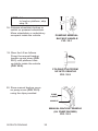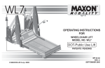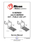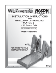
1
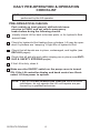
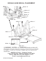
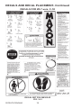
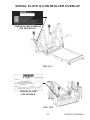
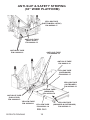
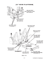
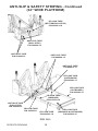
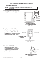
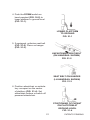
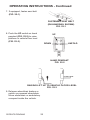
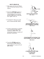
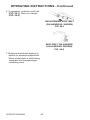
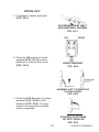
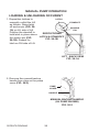
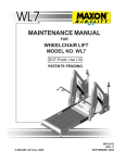
OPERATING INSTRUCTIONS
FOR
WHEELCHAIR LIFT MODEL NO.
• WL7-vers. C
• WL7-vers. C-1K
DOT-Public Use Lift
‘‘DOT-Public Use Lift’’ verifies that this platform lift meets the
‘‘public use lift’’ requirements of FMVSS No. 403. This lift may be
installed on all vehicles appropriate for the size and weight of
the lift, but must be installed on buses, school buses, and multipurpose passenger vehicles other than motor homes with a gross
vehicle weight rating (GVWR) that exceeds 4,536 kg (10,000 lb).
PATENTS PENDING
© MAXON Lift Corp. 2009
1
MP-06-10
REV. A
APRIL 2009
PATENTS PENDING
PATENTS PENDING
TABLE OF CONTENTS
INTRODUCTION ............................................................................................... 4
SAFETY SUMMARY ......................................................................................... 4
DAILY PRE-OPERATION & OPERATION CHECKLIST .................................. 6
MAINTENANCE SCHEDULE ........................................................................... 8
LIFT COMPONENTS & TERMINOLOGY........................................................ 10
DECALS AND DECAL PLACEMENT .............................................................. 12
DECALS FOR WL7-vers. C............................................................................. 13
DECALS FOR WL7-vers. C-1K ...................................................................... 14
SERIAL PLATE & CONTROLLER OVERLAY ................................................. 15
ANTI-SLIP & SAFETY STRIPING .................................................................. 16
OPERATING INSTRUCTIONS ....................................................................... 20
ENTER VEHICLE ............................................................................................ 20
EXIT VEHICLE ................................................................................................ 23
STOW LIFT ..................................................................................................... 25
MANUAL PUMP OPERATION........................................................................ 26
LOADING & UNLOADING OCCUPANT.......................................................... 26
PATENTS PENDING
INTRODUCTION
This manual contains safety information and operating instructions for
the Maxon Wheelchair and Standing Occupant Lift. Read and understand the WARNINGS, SAFETY CONSIDERATIONS, and operating
instructions in this manual, before operating the Lift.
SAFETY SUMMARY
! WARNING
1. This Wheelchair Lift is intended for commercial use only and
should be operated by an attendant. Do not attempt to ride Lift
without the assistance of an attendant.
2. Incorrect operation of this Lift can result in serious personal
injury. Comply with the WARNINGS and Lift operating instructions in this manual. Do not allow untrained persons to operate
the Lift. If you need to replace an Operator’s Manual, additional
copies are available from:
MAXON Lift Corp.
11921 Slauson Ave.
Santa Fe Springs, CA 90670
(800) 227-4116
3. Do not exceed rated load capacity of Lift which is 800 lbs.
(364 kg) for standard models and 1000 lbs. (453 kg) for the
WL7-vers. C-1K. Refer to WARNING-CAPACITY decal “J” on
the Lift.
4. Do not allow any part of your body, or the Lift occupant’s body,
to be placed under, within, or around any portion of the moving
Lift or its mechanisms, or in a position that would trap either of
you between the platform and the ground (or vehicle) when Lift
is operated.
5. Consider the safety and location of bystanders and location of
nearby objects when operating the Lift. Stand to one side of
platform while operating the Lift. Be certain that the area the Lift
will move through during operation is clear of all obstacles.
PATENTS PENDING
4
6. If possible, park the vehicle on level ground. Always set the
vehicle emergency brake before operating the Lift. If the Lift is
operated without setting the emergency brake, it may create a
hazard for occupant and attendant.
7. Comply with all attached instruction decals and warning decals.
8. Above all, USE GOOD COMMON SENSE when operating this
Lift.
9. Do not move vehicle when the wheelchair door is open.
10. MAXON recommends positioning the wheelchair so most of the
weight is by the inboard rollstop (see illustration below).
PLATFORM
OUTBOARD
ROLLSTOP
INBOARD
ROLLSTOP
11. An ambulatory (standing) occupant may face outboard or
inboard. If possible, position ambulatory occupant on the Lift,
facing the direction of travel (face vehicle when entering, face
away when exiting) and holding on the handrails.
5
PATENTS PENDING
DAILY PRE-OPERATION & OPERATION
CHECKLIST
NOTE: PRE-OPERATION and OPERATION CHECKS should be
performed by the Lift operator.
PRE-OPERATION CHECKS
Park vehicle on level ground, shift vehicle transmission to PARK, and set vehicle emergency
brake before doing the following checks.
Visually check Lift for bent or broken parts, or for hydraulic fluid
around base.
Check for hydraulic fluid leaking from cylinders. Lift may be operated if cylinders are “weeping” a light film of hydraulic fluid.
Check that all decals are in place, undamaged, and legible (see
DECALS pages).
Check that all anti-slip and safety striping are in place (see ANTISLIP & SAFETY STRIPING pages).
If the Lift is dirty, clean it.
Make sure the ON/OFF switch on the pump cover is turned
ON. If the Lift controller display and hand control are illuminated, Lift has power to operate.
NOTE: If any of the PRE-OPERATION CHECKS have incorrect
indications, do not operate the Lift until repairs are performed by a qualified technician.
PATENTS PENDING
6
OPERATION CHECKS
Operate the Lift through one full cycle and do the following
checks.
Use Lift operating instructions in this manual to UNFOLD,
LOWER, RAISE, and FOLD platform.
Make sure the Lift responds properly to switches on the
hand pendant.
Listen for unusual noises while the Lift operates.
Watch for uneven movement of the Lift arms, platform, and
inboard and outboard rollstops.
NOTE: If any of the OPERATION CHECKS have
incorrect indications, discontinue operating
Lift until repairs are performed by a qualified
technician.
7
PATENTS PENDING
MAINTENANCE SCHEDULE
NOTE: The Lift controller (brain box) counts the number of cycles & lifts
over the lifetime of the Lift. One CYCLE is counted each time
the Lift is unfolded from the stowed position to floor level, lowered to the ground, raised to floor level, and then stowed. One
LIFT is counted each time the Lift is lowered from floor level to
the ground, and raised back to floor level. Read the LIFTS and
CYCLES counts from the Lift brain box display window periodically so you know when to do the maintenance checks listed
below.
NOTE: Only a qualified technician should do the scheduled maintenance on this page and confirm compliance with Federal
Motor Vehicle Safety Standard 403. For the compliance
checks, refer to the COMPLETED LIFT INSTALLATION
CHECKLIST in Installation Manual MP-06-09.
EVERY 500 LIFTS
Visually check the Lift for bent, broken, or worn out parts, and broken
welds.
Check the electrical wiring for worn insulation, and the terminals for corrosion and secure fit. Apply dielectric grease to connections if needed.
Check for loose fasteners (nuts, bolts, screws & rivets). Also, check cotter
pins, clevis pins, retaining ring pins & retaining rings for noticeable wear
and damage.
Check that all decals are in place, undamaged, and legible (see DECALS
AND DECAL PLACEMENT pages).
Check that all anti-slip and safety striping are in place and undamaged
(see ANTI-SLIP & SAFETY STRIPING pages).
Clean dust and debris from outboard switch & ground switch (magnetic
switches on platform). (See ELECTRICAL COMPONENTS in the Maintenance Manual.)
EVERY 2500 CYCLES
Visually inspect the latch solenoids. If necessary, replace both latch solenoids P/N 266955-01.
Apply multi-use teflon spray lubricant to the inboard rollstop spring lock &
the plunger switch spring on the Lift.
EVERY 5000 LIFTS
Replace both platform light bulbs P/N 906475-01.
EVERY 10000 LIFTS
Check both hydraulic cylinders for leaks. If a film of hydraulic fluid is
visible on cylinder seals, Lift can still be operated. However, if fluid is dripping from the cylinders, replace them.
PATENTS PENDING
8
THIS PAGE INTENTIONALLY LEFT BLANK
9
PATENTS PENDING
LIFT COMPONENTS & TERMINOLOGY
INBOARD
RIGHT
10
6
4
11
10
6
7
8
12
5
2
9
1
12
3
LEFT
OUTBOARD
LIFT COMPONENTS (SEE TABLE 11-1)
FIG. 10-1
PATENTS PENDING
10
ITEM
NAME
DESCRIPTION
1.
THRESHOLD PLATE
Component that bridges the entry way,
through the Lift, into the vehicle. Detects if
that portion of Lift is occupied during “UP/
DOWN” operation between vehicle floor and
the ground.
2.
OUTBOARD ROLLSTOP
Barrier to prevent the wheelchair from rolling
off of the platform. Also provides entry/exit
ramp for platform on the ground.
3.
PLATFORM
Contains the wheelchair and occupant during
“UP/DOWN” operation between vehicle floor
and the ground.
4.
HANDRAILS
(Left/Right) Provides a hand hold for the Lift
occupant.
5.
INBOARD ROLLSTOP
Barrier to prevent the wheelchair from rolling
off inboard side of platform. Also, provides
bridge between platform and threshold.
6.
HYDRAULIC CYLINDER
(Left/Right) Telescoping steel tube and rod,
pressurized by hydraulic fluid, that folds and
unfolds the Lift and moves the Lift up and
down.
7.
HYDRAULIC POWER UNIT
(COVER IS SHOWN)
Contains motorized hydraulic pump, manually
operated backup pump, fluid lines, and
controls to operate the hydraulic cylinders.
8.
LIFT CONTROLLER
(BRAIN BOX)
Electronic device that controls and monitors
Lift operation and the interlock connection
with the vehicle.
9.
BASE
Structure that secures Lift to the vehicle
floor.
10.
THRESHOLD WARNING
BEACON
Flashing red light indicates threshold is
occupied by a person or object when the
platform is below floor level. Also indicates
outboard rollstop is open if platform is at
floor level.
11.
THRESHOLD WARNING
ALARM
Audible alarm sounds when threshold is
occupied by a person or object when the
platform is below floor level. Also indicates
outboard rollstop is open if platform is at
floor level.
12.
PLATFORM LIGHTS
Illuminates the platform when ready to load at
floor level and during “UP/DOWN” operation
between vehicle floor and the ground.
TABLE 11-1
11
PATENTS PENDING
DECALS AND DECAL PLACEMENT
DECAL ”D”
DECAL “O”
DECAL “K”
DECAL “A”
DECAL “B”
DECAL “F”
DECAL “L”
DECAL “M”
DECAL“J”
DECAL “I”
DECAL“N”
DECAL “C”
DECAL
“E”
DECAL“N”
DECAL “H”
FIG. 12-1
All WARNING, CAUTION, and OPERATION decals provided with
Wheelchair Lift must always be in place on the Lift and must always
be legible. If decals are missing or illegible, get free replacement
decals from:
MAXON Lift Corp. - Customer Service
11921 Slauson Ave., Santa Fe Springs, CA 90670
Phone: (800) 227-4116 FAX: (888) 771-7713
E-mail: [email protected]
PATENTS PENDING
12
DECALS FOR WL7-vers. C
DECAL SET P/N 268302-01
FIG. 13-1
13
PATENTS PENDING
DECALS AND DECAL PLACEMENT- Continued
DECALS FOR WL7-vers. C-1K
DECAL SET P/N 268302-03
FIG. 14-1
PATENTS PENDING
14
SERIAL PLATE & CONTROLLER OVERLAY
CONTROLLER OVERLAY
P/N 2667630-01
FIG. 15-1
SERIAL PLATE
P/N 905246-8
FIG. 15-2
15
PATENTS PENDING
ANTI-SLIP & SAFETY STRIPING
(30” WIDE PLATFORM)
YELLOW TAPE
(BOTTOM-ROLLSTOP)
P/N 905293-17
ANTI-SLIP TAPE
(ROLLSTOP)
P/N 096020-13
ANTI-SLIP TAPE
P/N 096020-10
ANTI-SLIP TAPE
P/N 096024-10
ANTI-SLIP TAPE
P/N 096013-10
YELLOW TAPE
(OUTBOARD)
P/N 905293-11
YELLOW TAPE
(OUTBOARD)
P/N 905293-14
YELLOW TAPE
(INBOARD)
P/N 905293-16
ANTI-SLIP TAPE
(ROLLSTOP)
P/N 096020-13
YELLOW TAPE
P/N 905293-11
YELLOW TAPE
P/N 905293-14
FIG. 16-1
PATENTS PENDING
16
YELLOW TAPE
(INBOARD & OUTBOARD)
P/N 905293-13
(33” WIDE PLATFORM)
YELLOW TAPE
(BOTTOM-ROLLSTOP)
P/N 905293-18
ANTI-SLIP TAPE
(ROLLSTOP)
P/N 096020-14
ANTI-SLIP TAPE
P/N 096020-11
ANTI-SLIP TAPE
P/N 096024-11
ANTI-SLIP TAPE
P/N 096013-11
YELLOW TAPE
(OUTBOARD)
P/N 905293-11
YELLOW TAPE
(OUTBOARD)
P/N 905293-14
YELLOW TAPE
(INBOARD)
P/N 905293-16
ANTI-SLIP TAPE
(ROLLSTOP)
P/N 096020-14
YELLOW TAPE
P/N 905293-11
YELLOW TAPE
P/N 905293-14
YELLOW TAPE
(INBOARD & OUTBOARD)
P/N 905293-15
FIG. 17-1
17
PATENTS PENDING
ANTI-SLIP & SAFETY STRIPING - Continued
(34” WIDE PLATFORM)
YELLOW TAPE
(BOTTOM-ROLLSTOP)
P/N 905293-18
ANTI-SLIP TAPE
(ROLLSTOP)
P/N 096020-15
ANTI-SLIP TAPE
P/N 096020-12
ANTI-SLIP TAPE
P/N 096024-12
ANTI-SLIP TAPE
P/N 096013-11
YELLOW TAPE
(OUTBOARD)
P/N 905293-11
YELLOW TAPE
(OUTBOARD)
P/N 905293-14
YELLOW TAPE
(INBOARD)
P/N 905293-16
ANTI-SLIP TAPE
(ROLLSTOP)
P/N 096020-15
YELLOW TAPE
P/N 905293-11
YELLOW TAPE
P/N 905293-14
FIG. 18-1
PATENTS PENDING
18
YELLOW TAPE
(INBOARD & OUTBOARD)
P/N 905293-15
THIS PAGE INTENTIONALLY LEFT BLANK
19
PATENTS PENDING
OPERATING INSTRUCTIONS
ENTER VEHICLE
NOTE: If equipped, seat belt must be fastened for Lift
to operate.
1. Fully open and secure Wheelchair Lift access door(s) on the
vehicle.
ON
OFF
PUMP
COVER
POWER SWITCH
(LH PUMP SHOWN)
FIG. 20-1
2. Apply power to the Lift by
turning on the switch on the
pump cover (FIG. 20-1). The
POWER light on the hand pendant illuminates (FIG. 20-2).
DOWN
UNFOLD
POWER (ON)
LIGHT
HAND PENDANT
FIG. 20-2
3. Push the UNFOLD switch on
hand pendant (FIG. 20-2)
to unfold platform to horizontal position (FIG. 20-3) until
platform lights come on.
FLOOR LEVEL
PLATFORM
LIGHT
UNFOLD PLATFORM
FIG. 20-3
PATENTS PENDING
20
4. Push the DOWN switch on
hand pendant (FIG. 18-2) to
lower platform to ground level
(FIG. 21-1).
LOWER PLATFORM
TO GROUND
FIG. 21-1
5. If equipped, unfasten seat belt
(FIG. 21-2). Place on hanger
(FIG. 21-3).
UNFASTENING SEAT BELT
(RH HANDRAIL SHOWN)
FIG. 21-2
SEAT BELT ON HANGER
(LH HANDRAIL SHOWN)
FIG. 21-3
6. Position wheelchair or ambulatory occupant on the center
of platform (FIG. 21-4). Set
wheelchair brakes or switch off
powered wheelchair.
POSITIONING OCCUPANT
ON PLATFORM AT
GROUND LEVEL
FIG. 21-4
21
PATENTS PENDING
OPERATING INSTRUCTIONS - Continued
7. If equipped, fasten seat belt
(FIG. 22-1).
FASTENING SEAT BELT
(RH HANDRAIL SHOWN)
FIG. 22-1
8. Push the UP switch on hand
pendant (FIG. 22-2) to raise
platform to vehicle floor level
(FIG. 22-3).
UP
DOWN
UNFOLD
HAND PENDANT
FIG. 22-2
RAISING LIFT UP TO VEHICLE FLOOR LEVEL
FIG. 22-3
9. Release wheelchair brakes or
switch on powered wheelchair.
Move wheelchair or ambulatory
occupant inside the vehicle.
PATENTS PENDING
22
EXIT VEHICLE
1. Fully open and secure Wheelchair Lift access door(s) on the
vehicle.
FLOOR LEVEL
PLATFORM
LIGHT
2. Push the UNFOLD switch on
hand pendant (FIG. 22-2) to
unfold platform to horizontal
position (FIG. 23-1) until platform lights come on.
UNFOLD PLATFORM
FIG. 23-1
3. If equipped, make sure seat
belt is fastened (FIG. 23-2).
FASTENING SEAT BELT
(RH HANDRAIL SHOWN)
FIG. 23-2
4. Position wheelchair or ambulatory occupant on the center
of platform (FIG. 23-3). Set
wheelchair brakes or switch off
powered wheelchair.
POSITIONING OCCUPANT ON
PLATFORM AT FLOOR LEVEL
FIG. 23-3
5. Push the DOWN switch on
hand pendant (FIG. 22-2) to
lower platform to ground level
(FIG. 23-4).
LOWERING PLATFORM
TO GROUND
FIG. 23-4
23
PATENTS PENDING
OPERATING INSTRUCTIONS - Continued
6. If equipped, unfasten seat belt
(FIG. 24-1). Place on hanger
(FIG. 24-2).
UNFASTENING SEAT BELT
(RH HANDRAIL SHOWN)
FIG. 24-1
SEAT BELT ON HANGER
(LH HANDRAIL SHOWN)
FIG. 24-2
7. Release wheelchair brakes or
switch on powered wheelchair.
Move wheelchair or ambulatory
occupant into the passenger
unloading zone.
PATENTS PENDING
24
STOW LIFT
1. If equipped, fasten seat belt
(FIG. 25-1).
FASTENING SEAT BELT
(RH HANDRAIL SHOWN)
FIG. 25-1
UP
2. Push the UP switch on hand
pendant (FIG. 25-2) to raise
platform to vehicle floor level
(FIG. 25-3).
FOLD
HAND PENDANT
FIG. 25-2
RAISING LIFT TO VEHICLE
FLOOR LEVEL
FIG. 25-3
3. Push the FOLD switch on hand
pendant (FIG. 25-2) to fold
platform (FIG. 25-4). Fold operation will stop automatically
when completed.
FOLDING PLATFORM
UP INTO VEHICLE
FIG. 25-4
25
PATENTS PENDING
MANUAL PUMP OPERATION
LOADING & UNLOADING OCCUPANT
LATCH
1. Reposition latches to
manually unfold the Lift
as follows. Raise latch
off anchor pin (FIG. 261A) on LH side of Lift.
Position the standoff to
REPOSITIONED
hold latch in place above
LATCH & STANDOFF
the anchor pin (FIG.
FIG. 26-1B
26-1B). Repeat for
latch on RH side of Lift.
STANDOFF
ANCHOR
PIN
LIFT - BACK VIEW
FIG. 26-1A
2. Remove the manual backup
handle from clips on the pump
cover (FIG. 26-2).
PUMP
COVER
HANDLE
MANUAL BACKUP HANDLE
(LH PUMP SHOWN)
FIG. 26-2
PATENTS PENDING
26
3. Unfold the platform as follows. Open release valve
on manual pump by turning
manual backup handle counter-clockwise (FIG. 27-1).
Start with 1/4 turn and slowly
increase to 1/2 turn counterclockwise.
1/4 - 1/2 TURN
OPEN RELEASE VALVE
FIG. 27-1
4. Observe the platform unfolding
to horizontal position at vehicle
floor level (FIG. 27-2).
UNFOLD PLATFORM
FIG. 27-2
5. When the platform reaches
floor level, close release valve
on manual pump by turning
manual backup handle clockwise until tight (FIG. 27-3).
TIGHTEN
CLOSE RELEASE VALVE
FIG. 27-3
27
PATENTS PENDING
MANUAL PUMP OPERATION - Continued
OUTBOARD
ROLLSTOP
6. Ensure outboard rollstop is
raised all the way (FIG. 28-1).
OUTBOARD ROLLSTOP
RAISED UP
FIG. 28-1
7. If equipped, make sure seat
belt is fastened (FIG. 28-2).
FASTENING SEAT BELT
(RH HANDRAIL SHOWN)
FIG. 28-2
NOTE: If there are no occupants to unload from
vehicle, skip step 8.
8. Position wheelchair or ambulatory occupant on the center
of platform (FIG. 28-3). Set
wheelchair brakes or switch off
powered wheelchair.
PATENTS PENDING
POSITIONING OCCUPANT
ON PLATFORM
FIG. 28-3
28
9. Lower the platform as follows.
Re-enter the vehicle to access
manual pump. Open release
valve on manual pump by
turning manual backup handle
counter-clockwise (FIG. 291). Lower the Lift slowly below
floor level and check if inboard
rollstop is raised and locked in
the up position (FIG. 29-2).
OPEN RELEASE VALVE
FIG. 29-1
INBOARD
ROLLSTOP
PLATFORM LOWERED,
INBOARD ROLLSTOP UP
FIG. 29-2
10. Watch platform (FIG. 293) as it lowers occupant to
the ground.
LOWERING PLATFORM
TO GROUND
FIG. 29-3
11. When platform rests on the
ground, close release valve
on manual pump by turning
manual backup handle clockwise until tight (FIG. 29-4).
TIGHTEN
CLOSE RELEASE VALVE
FIG. 29-4
29
PATENTS PENDING
MANUAL PUMP OPERATION - Continued
12. If equipped, unfasten seat
belt (FIG. 30-1). Place on
hanger (FIG. 30-2).
UNFASTENING SEAT BELT
(RH HANDRAIL SHOWN)
FIG. 30-1
SEAT BELT ON HANGER
(LH HANDRAIL SHOWN)
FIG. 30-2
13. Ensure outboard rollstop on
the platform is opened to
the horizontal position (FIG.
30-3).
OUTBOARD
ROLLSTOP
NOTE: If there are no occupants to unload, skip
steps 14 & 15.
OUTBOARD ROLLSTOP IN
HORIZONTAL POSITION
FIG. 30-3
14. Release wheelchair brakes or
switch on powered wheelchair.
Move wheelchair or ambulatory occupant into the unloading zone.
15. Position wheelchair or ambulatory occupant on the center
of platform (FIG. 30-4). Set
wheelchair brakes or switch
off powered wheelchair.
POSITIONING OCCUPANT
ON PLATFORM
FIG. 30-4
16. If equipped, fasten seat belt
(FIG. 30-5).
PATENTS PENDING
30
FASTENING SEAT BELT
(RH HANDRAIL SHOWN)
FIG. 30-5
CAUTION
Prevent the manual backup handle from getting damaged. Before you start pumping with the handle, line up notches on tip
of handle as shown in FIG. 29-1. Then fully engage handle with
manual pump as shown in FIG. 29-2.
NOTCHES LINED
UP VERTICAL
HANDLE - NOTCHES
LINED UP CORRECTLY
FIG. 31-1
HANDLE FULLY ENGAGED
FIG. 31-2
17. Raise the platform as follows.
Insert manual backup handle
in manual pump actuator.
Pump the handle up and
down (FIG. 31-3) until platform is raised up even with
the vehicle floor (FIG. 31-4)
and inboard rollstop lowers to
rest on threshold plate.
PUMPING MANUAL
BACKUP HANDLE
FIG. 31-3
RAISING LIFT TO
VEHICLE FLOOR
FIG. 31-4
31
PATENTS PENDING
NOTE: If there are no occupants
to load on platform, skip
step 18.
18. Release wheelchair brakes or
switch on powered wheelchair.
Move wheelchair or ambulatory
occupant inside the vehicle.
PUMPING MANUAL
BACKUP HANDLE
FIG. 32-1
19. Stow the Lift as follows.
Pump the manual backup
handle up and down (FIG.
32-1) until platform folds
up tightly inside the vehicle
(FIG. 32-2).
FOLDING PLATFORM
UP INTO VEHICLE
FIG. 32-2
20. Store manual backup cover
on pump cover (FIG. 32-3)
using the clips provided.
PUMP
COVER
HANDLE
MANUAL BACKUP HANDLE
(LH PUMP SHOWN)
FIG. 32-3
PATENTS PENDING
32