1
SERVICE
MANUAL
REVISION 0
FEB. 1998
COPYRIGHT © 1998 CANON INC.
FY8-13F4-000
CANON NP6621 REV.0 FEB. 1998 PRINTED IN JAPAN (IMPRIME AU JAPON)
IMPORTANT
THE INFORMATION CONTAINED HEREIN IS PUBLISHED BY CANON, INC., JAPAN, AND IS
FOR REFERENCE USE ONLY. SPECIFICATIONS AND OTHER INFORMATION CONTAINED
HEREIN MAY VARY SLIGHTLY FROM ACTUAL MACHINE VALUES OR THOSE FOUND IN
ADVERTISING AND OTHER PRINTED MATTER.
ANY QUESTIONS REGARDING INFORMATION CONTAINED HEREIN SHOULD BE DIRECTED
TO THE COPIER SERVICE DEPARTMENT OF THE SALES COMPANY.
COPYRIGHT © 1998 CANON INC.
Printed in Japan
Imprimé au Japon
Use of this manual should be
strictly supervised to avoid
disclosure of confidential
information.
Prepared by
OFFICE IMAGING PRODUCTS TECHNICAL SUPPORT DEPARTMENT 1
OFFICE IMAGING PRODUCTS TECHNICAL SUPPORT DIVISION
CANON INC.
5-1, Hakusan 7-chome, Toride-shi Ibaraki, 302-0023 Japan
COPYRIGHT © 1998 CANON INC.
CANON NP6621 REV.0 FEB. 1998 PRINTED IN JAPAN (IMPRIME AU JAPON)
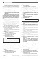
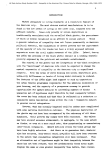
Introduction
This Service Manual provides basic facts and figures you will need to service the plain paper copier
NP6621 in the field.
The NP6621 is designed to enable automated copying work and may be configured with the following
accessory; for servicing information on the sorter, ADF, and control card, see their respective Service
Manuals:
1. Cassette Feeding Module-B2
2. Cassette Feeding Module-A2
3. Cassette Feeding Unit-K1
4. Paper Deck Pedestal-K1
5. Control Card IV N
6. ADF-E1
7. RDF-F1
8. Stapler Sorter-D1
9. Sorter 10-B1
10. Remote Diagnostic Device II
This Service Manual contains descriptions on the 1-Cassette Feeding Unit-B1 and the 2-Cassette Feeding
Unit-A2.
Note:
The Cassette Feeding Unit-B2, the Cassette Feeding Unit-A2 the cassette feeding Unit K1, the Paper
Deck Pedestal-K1 and Remote Diagnostic Device II may not be available for sale in some areas.
This Service Manual is organized as follows:
CHAPTER 1, “General Introduction,” explains the NP6621’s features, specifications, and step-by-step
instructions on how to operate the copier.
CHAPTER 2, “Copying Processes,” shows how the NP6621 generates copies while discussing each of
the steps involved.
CHAPTER 3, “Operations and Timing,” explains the NP6621’s mechanical system by function and
principles behind its electrical system in relation to timing of each operation.
CHAPTER 4, “Mechanical System,” provides instructions on how to disassemble/assemble and adjust the
NP6621.
CHAPTER 5, “Installation,” provides points to note when selecting the site of installation and instructions
on how to install the NP6621.
CHAPTER 6, ‘Maintenance and Inspection,” gives tables of periodically replaced parts and consumables/
durables as well as a scheduled servicing chart.
APPENDIX contains a general timing chart, general circuit diagrams, and PCB diagrams.
This Service Manual is accompanied by the Service Handbook, which provides information on how to
maintain and inspect the NP6621 through adjustment and troubleshooting work.
Information found in this manual may be updated from time to time for product improvement, and major
updates are communicated in the form of Service Information bulletins.
All service persons are expected to be thoroughly familiar with this Service Manual, the Service Handbook,
and Service Information bulletins and be ready to respond to the needs of the user.
COPYRIGHT © 1998 CANON INC.
CANON NP6621 REV.0 FEB. 1998 PRINTED IN JAPAN (IMPRIME AU JAPON)
i
Introduction
RDF-F1 (Recirculating Document Feeder)
Automatically feeds a set of up to 100 originals to the
platen glass for copying. The RDF can also turn over
two-sided originals for automatic two-sided copying.
MS-B1 (10 bins)
Automotically sorts and groups sets of up to
10 copies.
ADF-E1 (Automatic Document Feeder)
Automatically feeds sets of up to 30 originals to
the copyboard for copying.
Control Card IV N
Allows you to monitor the number of
copies made by each card holder.
Stapler Sorter-D2 (10 bins)
Automatically sorts or groups copies
into 10 bins at (30 pages per set).
Staples sets of up to 20 copies
each.
Cassette Feeding Module-B2
Allows you to increase your paper supply
through the addition of one paper cassette.
Cassette Feeding Module-A2
Allows you to increase your paper supply
through the addition of two paper cassettes.
Cassette Feeding Unit-K1
Allows you to increase your
paper supply through the addition
of three paper cassettes.
Paper Deck Pedestal-K1
Holds up to 1500 sheets of one type of paper.
ii
COPYRIGHT © 1998 CANON INC.
CANON NP6621 REV.0 FEB. 1998 PRINTED IN JAPAN (IMPRIME AU JAPON)
CONTENTS
CHAPTER 1 GENERAL DESCRIPTION
I. FEATURES ................................................ 1-1
II. SPECIFICATIONS ..................................... 1-2
A. Copier .................................................. 1-2
B. Cassette Feeding Module-B2/
Cassette Feeding Module-A2/Cassette
Feeding Unit-K1 .................................. 1-5
C. Paper Deck Pedestal-K1 ..................... 1-6
III. NAMES OF PARTS ................................... 1-7
A. Exterior ................................................ 1-7
B. Cross Section ...................................... 1-8
IV. BASIC OPERATION ................................ 1-13
A. Control Panel ..................................... 1-13
B. Making Copies ................................... 1-16
C. Using the Stack Bypass .................... 1-17
D. User Mode ......................................... 1-19
V. WARNINGS AND ACTIONS ................... 1-26
A. Jam Indicator ..................................... 1-26
B. Cleaning the Static Charge
Eliminator ........................................... 1-33
VI. ROUTINE CLEANING ............................. 1-34
CHAPTER 2 COPYING PROCESS
I.
IMAGE FORMATION ................................ 2-1
A. Outline ................................................. 2-1
B. Latent Static Image Formation Block .... 2-2
C. Step 1 (pre-exposure) ......................... 2-3
D. Step 2 (primary charging) .................... 2-3
E. Step 3 (image exposure) ..................... 2-4
F. Step 4 (development) .......................... 2-4
G. Step 5 (transfer) .................................. 2-5
H. Step 6 (separation) .............................. 2-6
I. Step 7 (fixing) ...................................... 2-7
J. Step 8 (drum cleaning) ........................ 2-7
II. AUXILIARY PROCESS ............................. 2-8
A. Blank Exposure ................................... 2-8
CHAPTER 3 OPERATIONS AND TIMING
I.
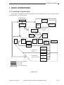
BASIC OPERATIONS ............................... 3-1
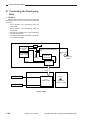
A. Functional Construction ....................... 3-1
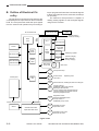
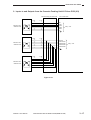
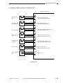
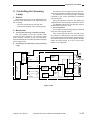
B. Outline of Electrical Circuitry ............... 3-2
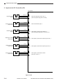
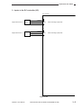
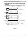
C. Inputs to the DC Controller .................. 3-3
D. Outputs from the DC Controller ........... 3-8
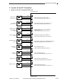
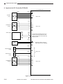
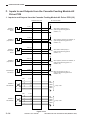
E. Inputs to and Outputs from the Cassette
Feeding Module-B2 Driver PCB ........ 3-13
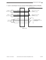
F. Inputs to and Outputs from the Cassette
Feeding Module-A2 Driver PCB ........ 3-14
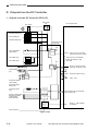
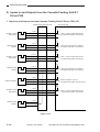
G. Inputs to and Outputs from the Cassette
Feeding Unit-K1 Driver PCB ............. 3-16
H. Main Motor Control Circuit ................. 3-21
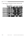
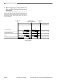
I. Basic Sequence of Operations
(2 copies, continuous, AE) ................ 3-22
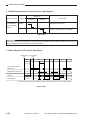
J. Original Size Detecton Control .......... 3-23
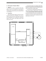
II. EXPOSURE SYSTEM ............................. 3-27
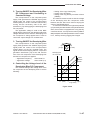
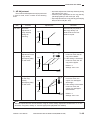
A. Varying the Reproduction Ratio ........ 3-27
B. Lens Drive System ............................ 3-27
C. Scanner Drive System ....................... 3-31
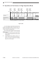
D. Operations of the Scanner in Page
Separation Mode ............................... 3-34
COPYRIGHT © 1998 CANON INC.
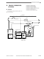
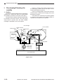
III. IMAGE FORMATION SYSTEM .............. 3-35
A. Outline ............................................... 3-35
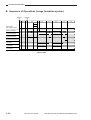
B. Sequence of Operations
(image formation system) .................. 3-36
C. Controlling the Scanning Lamp ......... 3-37
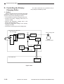
D. Controlling the Primary Charging
Roller ................................................. 3-38
E. Controlling the Transfer Roller Bias .... 3-41
F. Controlling the Static Eliminator
Bias .................................................... 3-44
G. Controlling the Developing Bias ........ 3-46
H. Copy Density Automatic Control ....... 3-48
I. Developing/Cleaning Assembly ........ 3-50
J. Blank Exposure Control ..................... 3-53
K. Primary Charging Roller Cleaning
Control ............................................... 3-55
L. Transfer Roller Locking/Releasing
Control ............................................... 3-56
IV. PICK-UP/FEEDING SYSTEM ................. 3-57
A. Pick-Up from the Machine ................. 3-57
B. Making Two-Sided Copies (1copy) ... 3-61
CANON NP6621 REV.0 FEB. 1998 PRINTED IN JAPAN (IMPRIME AU JAPON)
iii
C. Duplexing Unit ................................... 3-63
D. Pick-Up from the Cassette Feeding
Module-A2 ......................................... 3-72
E. Pick-Up from the Cassette Feeding
Unit-K1 ............................................... 3-74
F. Paper Deck Pedestal-K1 ................... 3-76
G. Multifeeder ......................................... 3-82
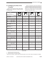
H. Identifying the Size of the Cassette ... 3-85
I. Fixing/Delivery Assembly .................. 3-87
J. Detecting Jams .................................. 3-92
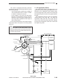
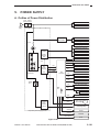
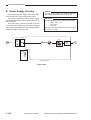
V. POWER SUPPLY .................................. 3-101
A. Outline of Power Distribution ........... 3-101
B. Power Supply Circuitry .................... 3-102
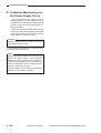
C. Detecting Errors on the Power Supply
PCB ................................................. 3-103
D. Protection Mechanisms for the Power
Supply Circuit .................................. 3-104
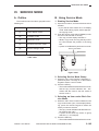
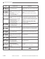
VI. SERVICE MODE ................................... 3-105
A. Outline ............................................. 3-105
B. Using Service Mode ........................ 3-105
C. Control Display Mode (‘1’) ............... 3-107
D. I/O Mode (‘2’) ................................... 3-110
E. Adjustment Mode (‘3’) ..................... 3-114
F. Operation/Inspection Mode (‘4’) ...... 3-117
G. Machine Settings Mode (‘5’) ............ 3-118
H. Counter Mode (‘6’) ........................... 3-120
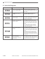
VII. SELF DIAGNOSIS ................................. 3-121
A. Copier Self Diagnosis ...................... 3-121
B. Self Diagnosis on the Cassette Feeding
Unit .................................................. 3-124
C. RDF/ADF Self Diagnosis ................. 3-125
D. Sorter Self Diagnosis ....................... 3-126
VIII. STANDARDS AND ADJUSTMENTS .... 3-127
A. Electrical .......................................... 3-127
CHAPTER 4 MECHANICAL SYSTEM
I.
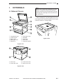
EXTERNALS ............................................. 4-1
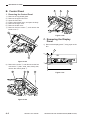
A. External Covers ................................... 4-1
B. Control Panel ....................................... 4-2
C. Removing the Display Panel ............... 4-2
D. Fan ...................................................... 4-3
E. Counter ................................................ 4-4
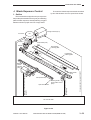
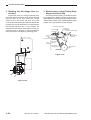
II. DRIVE SYSTEM ........................................ 4-5
A. Scanner Drive System ......................... 4-5
B. Lens Drive Assembly ......................... 4-10
C. Main Motor ......................................... 4-14
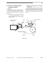
III. PICK-UP/FEEDING SYSTEM ................. 4-15
A. Pick-Up Assembly ............................. 4-15
B. Multifeeder Assembly ........................ 4-17
C. Registration Roller Assembly ............ 4-20
D. Feeding Assembly ............................. 4-22
E. Delivery Assembly ............................. 4-22
F. Duplexing Assembly .......................... 4-23
G. Cassette Unit ..................................... 4-24
H. Paper Deck Pedestal-K1 ................... 4-27
IV. EXPOSURE SYSTEM ............................. 4-34
A. Illuminating Assembly ........................ 4-34
V. CHARGING SYSTEM ............................. 4-38
A. Drum Unit .......................................... 4-38
B. Primary Charging Assembly .............. 4-39
C. Transfer Charging Assembly ............. 4-40
D. Drum Heater ...................................... 4-41
VI. DEVELOPING SYSTEM ......................... 4-42
VII. FIXING SYSTEM ..................................... 4-45
VIII.ELECTRICAL ........................................... 4-50
A. DC Controller PCB ............................ 4-50
B. Composite Power Supply PCB ......... 4-50
C. AE Sensor PCB ................................. 4-51
CHAPTER 5 INSTALLATION
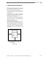
I. SELECTING THE SITE ............................. 5-1
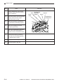
II. UNPACKING AND INSTALLING THE
COPIER ..................................................... 5-2
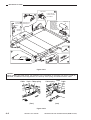
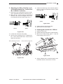
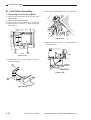
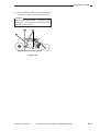
A. Unpacking and Removing Fixings ....... 5-2
B. Turning On the Copier ......................... 5-5
C. Checking the Images and
Operations ........................................... 5-7
D. Attaching the Drum Unit ...................... 5-8
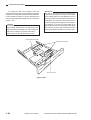
E. Changing the Cassette Size ................ 5-9
III. RELOCATING THE COPIER .................. 5-11
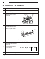
IV. REPLACING THE DRUM UNIT .............. 5-12
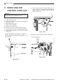
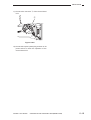
V. INSTALLING THE CONTROL
CARD IV N ............................................... 5-14
iv
COPYRIGHT © 1998 CANON INC.
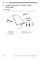
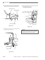
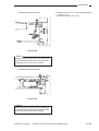
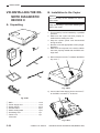
VI. CASSETTE HEATER KIT 5 INSTALLATION
PROCEDURE .......................................... 5-16
A. Unpacking .......................................... 5-16
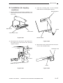
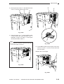
B. Installation (to copying machine) ....... 5-17
C. Installation (to a Cassette Feeding ModuleA2/B2/Cassette Feeding Unit-K1) ....... 5-20
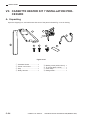
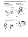
VII. CASSETTE HEATER KIT 7 INSTALLATION
PROCEDURE .......................................... 5-24
A. Unpacking .......................................... 5-24
B. Installation ......................................... 5-25
C. Attaching the Ratings Label .............. 5-27
VIII.INSTALLING THE REMOTE DIAGNOSTIC
DEVICE II ................................................ 5-28
A. Unpacking .......................................... 5-28
B. Installation to the Copier .................... 5-28
CANON NP6621 REV.0 FEB. 1998 PRINTED IN JAPAN (IMPRIME AU JAPON)
CHAPTER 6 MAINTENANCE AND SERVICING
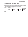
I.
PERIODICALLY REPLACED PARTS ....... 6-1
A. Periodically Replaced Parts ................ 6-1
II. DURABLES AND CONSUMABLES .......... 6-2
A. Copier .................................................. 6-2
B. Cassette Feeding Module-B2,
Cassette Feeding Module-A2,
and Cassette Feeding Unit-K1 ............ 6-3
C. Paper Deck Pedestal-K1 ..................... 6-3
III. BASIC SERVICING ................................... 6-4
IV. SERVICING CHART ................................. 6-5
A. Scheduled Maintenance Work ............ 6-5
APPENDIX
A.
B.
C.
D.
E.
F.
G.
H.
I.
J.
K.
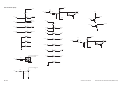
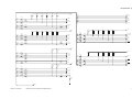
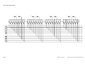
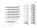
GENERAL TIMING CHART ..................... A-1
SIGNALS AND ABBREVIATIONS ........... A-2
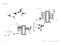
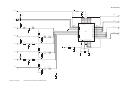
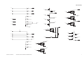
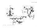
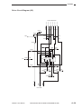
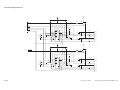
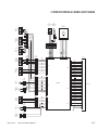
GENERAL CIRCUIT DIAGRAM ............... A-5
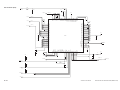
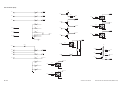
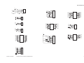
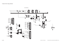
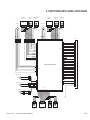
DC CONTROLLER CIRCUIT DIAGRAM ..... A-7
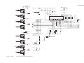
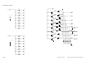
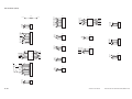
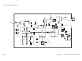
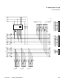
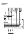
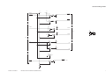
COMPOSITE POWER SUPPLY CIRCUIT
DIAGRAM ............................................... A-21
CONTROL PANEL KEY PCB ................ A-27
AE SENSOR CIRCUIT DIAGRAM ......... A-31
INTENSITY SENSOR CIRCUIT
DIAGRAM ............................................... A-32
TONER LEVEL DETECTION CIRCUIT
DIAGRAM ............................................... A-33
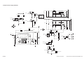
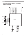
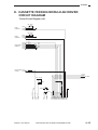
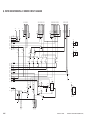
CASSETTE FEEDING MODULE-B2
GENERAL CIRCUIT DIAGRAM ............. A-34
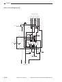
CASSETTE FEEDING MODULE-B2
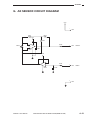
DRIVER CIRCUIT DIAGRAM ................ A-35
COPYRIGHT © 1998 CANON INC.
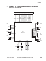
L. CASSETTE FEEDING MODULE-A2
GENERAL CIRCUIT DIAGRAM ............. A-37
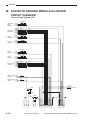
M. CASSETTE FEEDING MODULE-A2
DRIVER CIRCUIT DIAGRAM ................ A-38
N. CASSETTE FEEDING UNIT-K1 GENERAL
CIRCUIT DIAGRAM ............................... A-41
O. CASSETTE FEEDING UNIT-K1 ............ A-42
P. PAPER DECK PEDESTAL-K1 GENERAL
CIRCUIT DIAGRAM ............................... A-45
Q. PAPER DECK PEDESTAL-K1 DRIVER
CIRCUIT DIAGRAM ............................... A-46
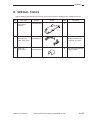
R. SPECIAL TOOLS ................................... A-47
S. SOLVENTS/OILS ................................... A-48
CANON NP6621 REV.0 FEB. 1998 PRINTED IN JAPAN (IMPRIME AU JAPON)
v
vi
COPYRIGHT © 1998 CANON INC.
CANON NP6621 REV.0 FEB. 1998 PRINTED IN JAPAN (IMPRIME AU JAPON)
CHAPTER 1
GENERAL DESCRIPTION
I. FEATURES ................................................ 1-1
II. SPECIFICATIONS ..................................... 1-2
A. Copier .................................................. 1-2
B. Cassette Feeding Module-B2/
Cassette Feeding Module-A2/Cassette
Feeding Unit-K1 .................................. 1-5
C. Paper Deck Pedestal-K1 ..................... 1-6
III. NAMES OF PARTS ................................... 1-7
A. Exterior ................................................ 1-7
B. Cross Section ...................................... 1-8
COPYRIGHT © 1998 CANON INC.
IV. BASIC OPERATION ................................ 1-13
A. Control Panel ..................................... 1-13
B. Making Copies ................................... 1-16
C. Using the Stack Bypass .................... 1-17
D. User Mode ......................................... 1-19
V. WARNINGS AND ACTIONS ................... 1-26
A. Jam Indicator ..................................... 1-26
B. Cleaning the Static Charge
Eliminator ........................................... 1-33
VI. ROUTINE CLEANING ............................. 1-34
CANON NP6621 REV.0 FEB. 1998 PRINTED IN JAPAN (IMPRIME AU JAPON)
COPYRIGHT © 1998 CANON INC.
CANON NP6621 REV.0 FEB. 1998 PRINTED IN JAPAN (IMPRIME AU JAPON)
GENERAL DESCRIPTION
I. FEATURES
When fitted with options, it provides a maximum of four paper sources.
1. Multiple front loading and multifeeder for space saving.
• The cassette may be slid out to the front for paper supply work.
• With the adjustable cassette and the multifeeder, various types of paper may be used.
2. Office conveniences and ecology.
• The copier is designed compact, enabling effective use of office space.
• The use of roller charging has proved to reduce the generation of ozone significantly.(1/100 to 1/1000
compared to other Canon copiers)
• As the pick-up mechanism, center-reference is adopted in consideration of the use of recycled paper.
• A significant number of parts are made of plastic in an effort to promote recycling.
• The copier is designed as a clamshell type to facilitate clearing of jammed paper.
3. Dependable high image quality.
• The new HQ (high-quality) toner ensures faithful reproduction of solid black, text, and photos.
• In addition to Canon’s own single-component toner projection development method, the use of auto
image control (AIC) ensures stable reproduction of images.
4. Practical basic features.
•
•
•
•
•
•
•
•
As many as 21 copies (A4/Letter, horizontal) may be made per minute.
Copies may be as large as A3/11×17 or as small as A5/STMT, accommodating postcards.
The AE mechanism promises enhanced reproduction of newspapers or diazo originals.
Using page separation mode, a book may be copies with its lift and right pages processed separately.
Copies may be made in zoom between 49% and 204%.
The zoom fine-adjustment mechanism ensures better control for faithful reproduction of originals.
The auto energy saver mechanism helps further saving of energy.
The interrupt mechanism enables cutting in on a continuous copying session.
COPYRIGHT © 1998 CANON INC.
CANON NP6621 REV.0 FEB. 1998 PRINTED IN JAPAN (IMPRIME AU JAPON)
1–1
GENERAL DESCRIPTION
II. SPECIFICATIONS
A. Copier
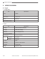
1. Configuration
Specifications
Item
Body
Desktop
Copyboard
Fixed
Light source
Halogen lamp
Lens
Zoom lens
Photosensitive medium
OPC
2. Type
Specifications
Item
Copying
Indirect electrostatic photography
Charging
Roller (direct charging)
Exposure
Slit (moving light source)
Copy density adjustment
Automatic (AE) or manual
Development
Dry (toner projection)
Automatic
2 cassettes
Manual
Multifeeder
Pick-up
Transfer
Roller
Separation
Curvature + static eliminator
Cleaning
Cleaning blade
Fixing
Heat roller, 900W
1–2
COPYRIGHT © 1998 CANON INC.
CANON NP6621 REV.0 FEB. 1998 PRINTED IN JAPAN (IMPRIME AU JAPON)
GENERAL DESCRIPTION
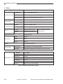
3. Performance
Item
Specifications
Sheet, book, 3-D object (2 kg/2.204 lb. max.)
Maximum original size
A3 (297 x 420 mm)
Reproduction ratio
DIRECT, 2R2E (Table 1-1);
zoom between 49% and 204% (fine zooming provided)
Wait time
30 sec
First copy time
9.7 sec (approx.; A4, DIRECT, non-AE, cassette 1)
Continuous copying
100 copies (max.; upper limit may be changed in service
mode)
Copying speed
See Table 1-202.
Copy size
Cassette: A3 to A5
Manual:
A3 to postcard
Copy paper type
Original type
Cassette
Plain paper (64g to 80 g/m2), tracing paper*1, colored paper*1,
recycled paper (64 to 80 g/m2), eco paper (80 g/m2)
Manual
Plain paper (64 to 80 g/m2), tracing paper*1, colored paper*1,
recycled paper (64 to 80 g/m2), eco paper (80 g/m2 *1), transparency*3, postcard, label sheet*1, Thick paper (81 to 128 g/m2)
Two-sided/overlay copying*2
Plain paper (64 to 80 g/m2), colored paper, postcard, recycled
paper (64 to 80 g/m2), eco paper (80 g/m2)
Cassette
34 mm deep (approx.; about 250 sheets of 80 g/m2); no claw,
front loading (center reference)
Multifeeder
5 mm (max. stacking height; i.e., about 50 sheets of 80 g/m 2);
no claw (center reference)
Copy tray
100 sheets (approx.: A3, 80 g/m2)
Non-image width
One-sided
2.0 ±1.0 mm (leading edge); 2.5 ±1.5 mm (left/right, trailing edge)
Multifeeder
2.0 ±1.0 mm (leading edge); 3.5 ±1.5 mm (left/right, trailing edge)
Auto clear
Provided (2 min standard; may be varied in 1-min increments
between 1 and 9 min; may be deactivated)
Auto power-off
Provided (5 min standard; 2, 5, 10, 15, 30, 60, or 120 min;
may be varied in user mode)
Options
Cassette Feeding Module-B2, Cassette Feeding Module-A2,
Cassette Feeding Unit-K1, Control Card IV N, Stapler SorterD2, Sorter 10-B1, ADF-E1, RDF-F1, Paper Deck PedestalK1, Remote Diagnostic Device II
*1 Canon recommended paper.
*2 If in manual mode, remove curling before second feeding.
*3 Fan out sheets before setting to eliminate adhesion.
COPYRIGHT © 1998 CANON INC.
CANON NP6621 REV.0 FEB. 1998 PRINTED IN JAPAN (IMPRIME AU JAPON)
1–3
GENERAL DESCRIPTION
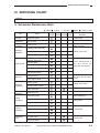
4. Others
Item
Operating environment
Specifications
Temperature
7.5° to 32.5°C/45.5 to 90.5°F
Humidity
5% to 85%
Atmospheric pressure
810.6 hPa to 10313.3 hPa (0.8 to 1 atm)
Serial numbers
Power supply
230 V (50Hz)
QBSxxxxx, UDNxxxxx, SBExxxxx, TBHxxxxx, UDPxxxxx
Standby
0.042 kwh (reference only)
Continuous copying
0.663 kwh (reference only)
Copying
66 dB or less (1m front)
Standby
40 dB or less (1m front)
Power consumption
Noise
0.02 ppm or less
Ozone (avr over 8 hr)
Dimensions
By ISO sound power level
measurement
Width
585 mm
Depth
640 mm
Height
624 mm
77 kg/169.8 lb (approx.)
Weight
Copy paper
Keep wrapped; store avoiding humidity.
Cartridge
Avoid direct sunshine; store at 40°C/104°F, 85% or less.
Consumables
DIRECT
1: 1 (±0.5%)
230V
Reproduction ratio
REDUCE I
1: 0.500
REDUCE II
1: 0.707
ENLARGE I
1: 1.414
ENLARGE II
1: 2.000
ZOOM
49% to 204 % (1% increments)
Table 1-201 Defaults Reproduction Ratio
1–4
COPYRIGHT © 1998 CANON INC.
CANON NP6621 REV.0 FEB. 1998 PRINTED IN JAPAN (IMPRIME AU JAPON)
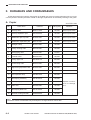
GENERAL DESCRIPTION
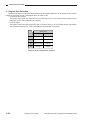
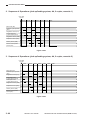
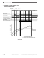
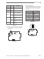
Copy size
Reproduction ratio
DIRECT
REDUCE
ENLARGE
1: 1 (±0.5%)
Q’ty
A3
(297 × 420)
11
A4
(210 × 297)
21
A5
(148 × 210)
21
B4
(257 × 364)
12
B5
(182 × 257)
21
A4R (297 × 210)
16
A5R (210 × 148)
18
B5R (257 × 182)
18
1: 0.500 (+1.0%)
A3
→
A5R
20
1: 0.707 (+1.0%)
A3
→
A4R
15
B4
→
B5R
17
1: 2.000 (+1.0%)
A5R →
A3
12
1: 1.414 (+1.0%)
A4R →
A3
12
B5R →
B4
14
Table 1-202 Copying Speeds
Specifications subject to change without notice.
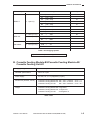
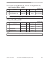
B. Cassette Feeding Module-B2/Cassette Feeding Module-A2/
Cassette Feeding Unit-K1
Copy paper type
Same as copier.
Cassette specifications
Same as copier
Power supply
34 VDC, 24 V, 5 V (supplied by copier)
Dimensions (WxDxH; mm/in)
Cassette Feeding Module-B2: 585 × 622 × 105/23.0 × 24.5 × 4.1
Cassette Feeding Module-A2: 585 × 622 × 210/23.0 × 24.5 × 8.3
Cassette Feeding Unit-KI:
585 × 622 × 384/23.0 × 24.5 × 15.1
Weight
Cassette Feeding Module-B2: 9 kg/19.8 lb
Cassette Feeding Module-A2: 16 kg/32.3 lb
Cassette Feeding Unit-KI:
29.6 kg/65.3 lb
Table 1-203
COPYRIGHT © 1998 CANON INC.
CANON NP6621 REV.0 FEB. 1998 PRINTED IN JAPAN (IMPRIME AU JAPON)
1–5
GENERAL DESCRIPTION
C. Paper Deck Pedestal-K1
Method of pick-up
Clawless
Loading method
Front loading
Type of paper
Plain paper (64 to 80 g/m2), Colored paper*
Size of paper
A4 (landscape), B5 (landscape), LTR (landscape)
Capacity
162 mm high (one side; equivalent of 1500 sheets of 80 g/m2 paper)
Switching (size)
Partitioning plate (incremental)
Control panel
No (use copier' s control panel)
Display
No (see copier' s display)
Power supply
34 VDC, 24 V, 5 V (supplied by copier)
Weight
31.7 kg/70.0 lb
Dimensions (W × D × H; mm/in)
610 × 583 × 414/24.0 × 21.4 × 16.3
Table 1-204
1–6
COPYRIGHT © 1998 CANON INC.
CANON NP6621 REV.0 FEB. 1998 PRINTED IN JAPAN (IMPRIME AU JAPON)
GENERAL DESCRIPTION
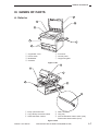
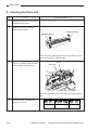
III. NAMES OF PARTS
1
A. Exterior
7
2
6
5
3
4
q
w
e
r
t Front door
y Control panel
u Copyboard glass
Copyboard cover
Power switch
Multifeeder
Cassette
Figure 1-301
1
6
2
5
3
4
r Static eliminator
t Copy tray
y Anti-condensation heater switch (rear)
Fluorescent heater switch (front)
Figure 1-302
q Body open/close lever
w Copy density correction volume
e Static eliminator cleaner
COPYRIGHT © 1998 CANON INC.
CANON NP6621 REV.0 FEB. 1998 PRINTED IN JAPAN (IMPRIME AU JAPON)
1–7
GENERAL DESCRIPTION
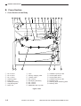
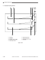
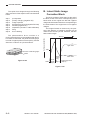
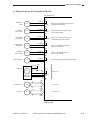
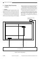
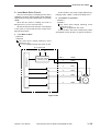
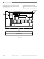
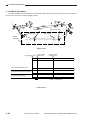
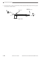
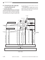
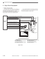
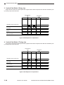
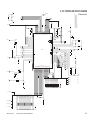
B. Cross Section
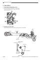
1. Cross Section of the Body
1
23
q
w
e
r
t
y
u
i
2
3
22
No. 3 mirror
No. 2 mirror
No. 1 mirror
Scanning lamp
Fixing unit
Feeding assembly
Copyboard glass
Drum unit
4
6
5
7
8
10
9
11
13
12
20
21
o
!0
!1
!2
!3
!4
!5
!6
Lens
Primary charging roller
Transfer roller
No. 6 mirror
Developing assembly
No. 4 mirror
No. 5 mirror
Multifeeder pick-up roller
!7
!8
!9
@0
@1
@2
@3
14
19
15
16
17
18
Cassette 1 pick-up roller
Vertical path roller 2
Vertical path roller 1
Cassette 2 pick-up roller
Duplexing unit
Delivery paper deflecting plate
Delivery roller
Figure 1-303
1–8
COPYRIGHT © 1998 CANON INC.
CANON NP6621 REV.0 FEB. 1998 PRINTED IN JAPAN (IMPRIME AU JAPON)
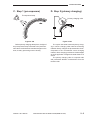
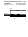
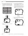
GENERAL DESCRIPTION
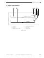
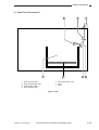
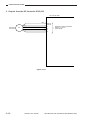
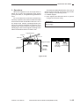
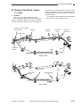
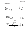
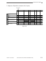
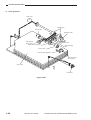
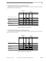
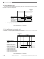
2. Cassette Feeding Module-A2
1
2
q Cassette 3
w Cassette 4
e Cassette 3 pick-up roller
3
4
5
6
r Cassette 4 pick-up roller
t Drive roller
y Feeding roller
Figure 1-304
COPYRIGHT © 1998 CANON INC.
CANON NP6621 REV.0 FEB. 1998 PRINTED IN JAPAN (IMPRIME AU JAPON)
1–9
GENERAL DESCRIPTION
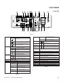
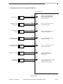
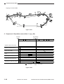
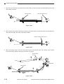
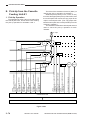
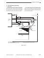
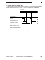
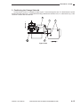
3. Cassette Feeding Unit-K1
1
2
3
9
q
w
e
r
t
8
y
u
i
o
Cassette 3
Cassette 4
Cassette 3 pick-up roller
Cassette 4 pick-up roller
Vertical path roller 4
4
6
5
7
Vertical path roller 3
Vertical path roller 5
Cassette 5 pick-up roller
Cassette 5
Figure 1-305
1–10
COPYRIGHT © 1998 CANON INC.
CANON NP6621 REV.0 FEB. 1998 PRINTED IN JAPAN (IMPRIME AU JAPON)
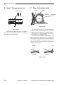
GENERAL DESCRIPTION
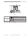
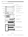
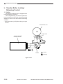
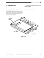
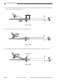
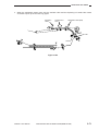
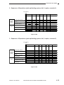
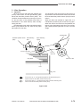
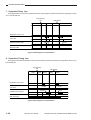
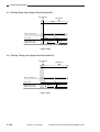
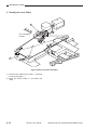
4. Paper Deck Pedestal-K1
1
2
3
7
q
w
e
r
Deck pick-up roller
Deck vertical path roller
Vertical path roller 3
Deck feeding roller
6
5
4
t Deck separation roller
y Lifter
u Deck
Figure 1-306
COPYRIGHT © 1998 CANON INC.
CANON NP6621 REV.0 FEB. 1998 PRINTED IN JAPAN (IMPRIME AU JAPON)
1–11
GENERAL DESCRIPTION
1–12
COPYRIGHT © 1998 CANON INC.
CANON NP6621 REV.0 FEB. 1998 PRINTED IN JAPAN (IMPRIME AU JAPON)
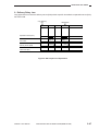
IV. BASIC OPERATION
1
2
4
3
5
7
8
6
9 10 11
12
13
15
14 16 17
18
20 21
19
24
22
25
23
A. Control Panel
26
Figure 1-401
q Sorter key
w Two-sided key (left side)
Press to set or cancel the Sort, Staple Sort, and Group modes.
Sort mode: When copying a multi-page document, copies are automatically sorted into
sets arranged in page order.
* To use this mode, your copier must be equipped with the optional Stapler Sorter, Sorter,
or ADF/RDF.
Staple Sort mode: When copying a multi-page document, copies are automatically sorted
into sets arranged in page order and then stapled.
* To use this mode, your copier must be equipped with the optional Stapler Sorter.
Group mode: When copying a multi-page document, all copies of the same original page
are grouped together, and output into different bins.
* To use this mode, your copier must be equipped with the optional Stapler Sorter or Sorter.
Press to set or cancel the following two-sided copy modes: 1 2-sided, 2 2-sided, 2 1-sided, Book 2-sided.
1 2-sided: Makes two-sided copies from one-sided originals.
2
A
3 · 5····
2 · 4····
e Two-sided key (right side)
2
2
2
2
AE key
Copy exposure key
Reduce/1:1/Enlarge key
Message display
Flashes when a paper jam occurs.
!0 Add Paper indicator
Flashes when the paper supply in the cassete or stack bypass tray runs out, and when the
cassette is not properly set.
Flashes when the toner runs low and must be replaced with a new one.
!1 Replace Toner Cartridge
indicator
!2 Paper Supply/Jam Location
indicator
!3 Paper select key
!4 Select paper size indicator
!5 Copy quantity/copy ratio
display
!6 OK key
!7 Auto Zoom key
1-sided: Makes one-sided copies from two-sided originals.
Book
2-sided: Makes two-sided copies from facing pages in a book.
Press to set or cancel the AE (Automatic Exposure) mode.
Press to manually adjust the copy exposure.
Press to enlarge or reduce using a preset copy ratio, or to return the copier to 100% copying (1:1).
Place originals in feeder
Flashes when the original in the feeder needs to be reloaded.
Enter frame erase/margin size
Flashes when the width of the edges to be erased or the margin needs to be
specified.
* Enter the measurement with the Number keys and then press the OK key.
Replace originals
Flashes when the first original copied needs to be replaced with the next one.
Set copy ratio
Flashes when the copy ratio needs to be specified.
* Enter the copy ratio with the preset copy ratio key, the reduce/1:1/enlarge
keys, or the Zoom key, and then press the OK key.
Select paper size
Flashes when the paper size needs to be specified.
* Select a paper size with the paper select key, and then press the OK key.
Enter original size
Flashes when the original size needs to be specified.
* Enter the original size with the Number keys and then press the OK key.
123
o Paper Jam indicator
!8 Zoom key
2
r
t
y
u
When you do not know the total page number of the original, the copier automatically
counts the original.
Select when you know beforehand that there is an odd number of originals. This will save
the time spent on counting the original.
Select this when you know beforehand that there is an even number of originals.
This will save the time spent on counting the original.
2 2-sided: Makes two-sided copies from two-side originals.
i Check Control Card indicator
Flashes when the original size needs to be selected.
* Select the original size with the paper select key, and then press the OK
key.
Flashes when the copy size needs to be entered.
* Enter the copy size with the Number keys, and then press the Ok key.
Flashes when the control card is not properly inserted.
!9
@0
@1
@2
@3
@4
@5
@6
% key
Reset key
Stop key
Number keys
Power switch
Start key
Clear key
Interrupt key
Lights to indicate the selected paper cassete or stack bypass. When a paper jam occurs, the location of the paper
jam flashes. It also lights when the Sorter or right door needs to be inspected, or when a paper jam occurs in the
ADF/RDF.
Press to select Auto Paper selection, a paper cassette, or the stack bypass.
The size of the original/copy paper selected with the Paper select key lights.
Displays the entered copy quantity copy ratio, and Additional Functions settings.
Press to confirm items and functions that have been selected when setting modes.
Press to set or cancel the Auto Zoom mode. Auto Zoom automatically selects the appropriate copy ratio, based on
the size of the originals and the selected copy paper.
Press to set or cancel the Zoom mode. Zoom mode allows you to specify a copy ratio from 49 to 204% in 1%
increments. Continue pressing for fast selection.
Press to display the selected copy ratio.
Press to return the settings to standard mode.
Press to stop the coper before copying is completed.
Press the enter copy quantity and other numerical values when setting a mode.
Press to turn the power ON and OFF.
Press to begin copying.
Press to return the copy quantity to one, or to clear an incorrectly entered value when setting a mode.
Press to temporarily stop the current copy job to make priority copies.
Table 1-402
Table 1-401
COPYRIGHT © 1998 CANON INC.
CANON NP6621 REV.0 FEB. 1998 PRINTED IN JAPAN (IMPRIME AU JAPON)
1–13
GENERAL DESCRIPTION
1–14
COPYRIGHT © 1998 CANON INC.
CANON NP6621 REV.0 FEB. 1998 PRINTED IN JAPAN (IMPRIME AU JAPON)
GENERAL DESCRIPTION
w
e
q
Figure 1-402
q Transparency Interleaving key
Press to set or cancel the Transparency Interleaving mode.
The interleaf sheets are printed with the same images as the transparencies.
The interleaf sheets are left blank.
w Two-page Separation/Image
Combination key (left side)
Copies facing pages in a bound original onto two copy sheets.
2 ON 1: Reduces two originals to fit on one side of a single copy sheet.
2
e Additional Functions key
2 ON 1/2 Sided: Reduces four originals to fit on two sides of a single copy sheet.
Press to set or change standard settings and custom settings according to specific user needs, and when
adjusting and cleaning the copier.
Table 1-403
COPYRIGHT © 1998 CANON INC.
CANON NP6621 REV.0 FEB. 1998 PRINTED IN JAPAN (IMPRIME AU JAPON)
1–15
GENERAL DESCRIPTION
B. Making Copies
1) Place your originals.
a. Placing originals on the platen glass
• Lift the platen glass cover.
• Place your original on the platen glass. The
surface that you want to copy must face
down. Align the edge of the original with the →
mark in the centre of the platen glass.
• Gently lower the platen glass cover.
3) Press the
key.
a. After copying begins, you cannot change the
number of copies, paper size, copy ratio or
other copy settings.
b. The copier’s counter automatically counts up
one as each copy is output to the copy tray.
1
2
4
5
7
8
C
0
Figure 1-405
Figure 1-403
b. Placing originals in the ADF or RDF (option)
• Adjust the slide guides to fit the size of your
originals.
• Neatly stack your originals face up in the
original tray.
c. If you want to stop the copier before copying is
key.
complete, press the
Reference:
key will not clear the copy
Pressing the
settings. To clear the copy settings, press the
key.
N
Figure 1-404
1
2
3
4
5
6
7
8
9
C
0
A
Figure 1-406
2) Programme the copy settings.
• Press the 0 - 9 keys to enter the number of
copies.
• Press the
keys to adjust the copy
exposure.
key to select the copy paper size.
• Press the
• Press the
keys to select a preset
copy ratio.
1–16
COPYRIGHT © 1998 CANON INC.
CANON NP6621 REV.0 FEB. 1998 PRINTED IN JAPAN (IMPRIME AU JAPON)
GENERAL DESCRIPTION
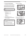
C. Using the Stack Bypass
1) Place your originals.
You can place up to 50 sheets of copy paper (a
stack approximately 5 mm high) in the stack bypass
to be automatically fed into the copier. Use the stack
bypass when you want to copy on special stock,
such as transparencies or labels, or when the paper
size that you want to copy on will not fit in a cassette.
Note:
Note the following points when using the stack
bypass:
a. Paper size: A5 (horizontal placement) to A3
b. Paper weight: 64 to 128 g/m2
c. Acceptable paper
• Plain paper (64 to 128 g/m2)
• Coloured paper
• No. 2 master drawing paper
• Labels
• Transparencies
• Postcards
• Recycled paper
d. Curl down copy stock before use.
e. There are some types of copy stock which meet
the above specifications but which cannot be
fed in the stack bypass.
Notes:
1. Do not use the sort/staple-sort/group mode
when copying postcards as it may result in
a paper jam.
2. A5R-size copy paper cannot be used to
make two-sided or overlay copies.
3. Insert A4-size labels horizontally.
4. If you want the copy stock placed in the
stack bypass to be selected when using
Auto Paper Selection, specify the size.
COPYRIGHT © 1998 CANON INC.
Figure 1-407
Figure 1-408
2) Programme the copy settings.
3) Open the stack bypass.
Figure 1-409
CANON NP6621 REV.0 FEB. 1998 PRINTED IN JAPAN (IMPRIME AU JAPON)
1–17
GENERAL DESCRIPTION
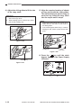
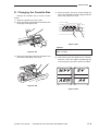
4) Adjust the slide guides to fit the size
of the copy stock.
Reference:
1. Be sure to adjust the slide guides to fit the
size of the copy stock.
2. When feeding A4R or A3-size copy stock,
pull out the auxiliary tray.
5) Align the required number of sheets
of copy stock with the slide guides.
The surface that you want to copy on
must face up. Insert the copy stock
into the copier until it stops.
Notes:
1. Make sure that the height of the paper is not
higher than the limit mark on the inside of
the slide guides.
2. If the Stack Bypass Size Entry in Custom
Settings is ON, select a paper size at this
point.
Figure 1-410
Maximum
level
Slide guides
Limit mark
Figure 1-412
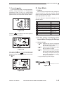
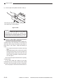
6) Press the
key until the stack
bypass lights on the Paper Supply
indicator.
Auxiliary tray
mm
%
Autom.Paper
Figure 1-411
A3
A4
A4 R
A5
A5 R
OK
Autom.Zoom
%
ZOOM
Figure 1-413
1–18
COPYRIGHT © 1998 CANON INC.
CANON NP6621 REV.0 FEB. 1998 PRINTED IN JAPAN (IMPRIME AU JAPON)
GENERAL DESCRIPTION
7) Press the
D. User Mode
key.
If you set the Two-sided, Two-page separation,
Overlay, Image Separation or Transparency
Interleaving modes in step 1 for stack bypass
feeding, and you have not selected the size of the
paper to be fed, the Paper Size indicator flashes.
1
2
4
5
7
8
C
0
Figure 1-414
key to select the size of the paper to
Press the
be fed into the stack bypass.
mm
%
Autom.Paper
A4
A5
A5 R
OK
Autom.Zoom
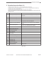
1. Outline
You can change or adjust the factory settings for
various functions to meet your specific copying
needs. It is also possible to perform cleaning and to
make adjustments to the copier.
You can change or adjust the settings for the
following items:
01
02
03
04
05
06
07
08
09
00
Function
Initial setting
Auto Clear Time
2 min.
Auto Energy Saver Time
5 min.
Zoom Fine Adjustment
0%
Auto Cassette Selection ON/OFF
ON
Stack Bypass Size Specification ON/OFF
OFF
Auto Sort ON/OFF
ON
Feeder Cleaning
Standard Copy Settings
Input Unit mm/Inch Selection
2 min.
Initializing Additional Functions NP Drum Cartridge Counter
Table 1-404
2. The Use of Keys and Displays That
Appear When Changing the Settings
%
a. The Use of Keys
key : Press this key to set or cancel the
•
Additional Functions and return to
the normal copying mode.
key : Press this key to indicate the item
•
that you want to change.
• C key : Press this key to clear any mistakes
that you have made when changing
the settings. Also press this key to
return to the last previous setting
that you had entered.
• Copy Quantity/Copy Ratio Display
Aditional
Function
ZOOM
OK
Figure 1-415
key. If the size you want cannot
Then press the
be selected, press the
key so that the Stack
Bypass Size Entry display disappears, then press
key.
the
OK
OK
mm
%
123
Autom.Paper
A3
Press the
A4
A4 R
A5
A5 R
OK
key.
OK
Autom.Zoom
•“
The number for a function that can be set.
The present setting for a certain function.
Figure 1-417
ZOOM
Figure 1-416
COPYRIGHT © 1998 CANON INC.
CANON NP6621 REV.0 FEB. 1998 PRINTED IN JAPAN (IMPRIME AU JAPON)
1–19
GENERAL DESCRIPTION
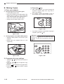
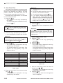
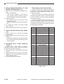
3. Auto Clear Time
If the copier is not operated (no keys are pressed)
for a certain period of time, the copier automatically
returns to the standard copy settings. This time
period is called the “Auto Clear Time.” You can
cancel or freely change the Auto Clear Time.
Auto Clear Time can be set from 1 to 9 minutes
in one-minute increments.
key.
1) Press the
• “U01” appears in the Copy quantity/Copy
ratio display.
To continue setting other Additional Functions,
press the 1 key.
Aditional
Function
Reference:
Once you set the Additional Functions mode,
the
key turns red and copying operations
cannot be initiated.
2) Check the Copy quantity/Copy ratio display.
If “U01” is displayed, proceed to the next step.
Reference:
If “U01” is not displayed or if you make a mistake
while entering a value, press either the 1 key or
press the C key and then the 1 key.
key.
3) Press the
• The current setting is displayed in the Copy
quantity/Copy ratio display.
• The possible settings for Auto Clear Time
appear in the Copy quantity / Copy ratio
display as follows:
OK
key.
5) Press the
The Auto Clear Time is changed and “U01” is
displayed.
OK
Reference:
key is pressed before the
key is
If the
pressed, the Auto Clear Time that was set is
cleared and the copier returns to the normal
copying mode.
OK
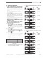
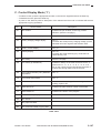
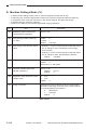
4. Auto Energy Saver Time
Aditional
Function
1) Press the
key.
• “U01” appears in the Copy quantity/Copy
ratio display.
2) Press the 2 key.
key.
3) Press the
• The current setting is displayed in the Copy
quantity/Copy ratio display.
The possible settings for Auto Energy Saver
Time appear in the Copy quantity / Copy ratio
display as follows:
OK
Auto Clear Time (min.)
Settings
Auto Energy Saver Time (min.)
Settings
0
–0
2
–1
1
–1
5
–2
2
–2
10
–3
3
–3
15
–4
4
–4
30
–5
5
–5
60
–6
6
–6
120
–7
7
–7
8
–8
9
–9
Table 1-405
4) Enter the Auto Clear Time with the Number
keys ( 0 - 9 ).
• The setting time is displayed in the Copy
quantity/Copy ratio display.
1–20
Reference:
1. The initial setting for the Auto Clear Time is
2 minutes.
2. You can set Auto Clear Time from 1 to 9
minutes, in one-minute increments.
3. To cancel this function, press the 0 key.
4. If you make a mistake while entering a
value, enter the correct value and it will
replace the incorrect one that was previously
entered, or press the C key and after the
display clears, enter the correct value.
COPYRIGHT © 1998 CANON INC.
Table 1-406
4) Enter the Auto Energy Saver Time with the
Number keys ( 1 - 7 ).
• The setting time is displayed in the Copy
quantity/Copy ratio display.
key.
5) Press the
• The Auto Energy Saver Time is changed and
“U02” is displayed.
OK
CANON NP6621 REV.0 FEB. 1998 PRINTED IN JAPAN (IMPRIME AU JAPON)
GENERAL DESCRIPTION
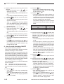
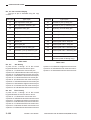
5. Zoom Fine Adjustment
• If there is a slight difference in size between the
original and output copy images when the copy
ratio is set to 100% (direct), use this function to
correct the error. Adjustments can be made
independently in the X (horizontal) and Y (vertical)
directions.
You can make adjustments from –1% to +1%, in
0.2% increments.
keys to adjust the copy ratio for
• Press the
Zoom Fine Adjustment. The zoom fine
adjustments can be confirmed by looking at the
copy exposure display.
• Confirm fine adjustments by making copies and
comparing them with the original.
key, the zoom fine
• Even if you press the
adjustments made in the Additional Functions
mode will not change.
• The zoom fine adjustments are also effective
when making reduced/enlarged copies.
key.
1) Press the
• “U01” appears in the Copy quantity/Copy
ratio display.
• Once you set the Additional Functions mode,
the key turns red and copying operations
cannot be initiated.
2) Press the 3 key.
• If you make a mistake while entering a value,
press either the key or press the C key and
then the key.
key.
3) Press the
• “–1” is displayed in the Copy quantity/Copy
ratio display, and the current setting in the X
direction is displayed in the copy exposure
display.
• The X,Y directions appear in the Copy quantity/
Copy ratio display as follows:
a. Zoom Fine Adjustment (Reduction): Press the
key.
Initial
setting
(±0%)
(–0.2%)
(–0.4%)
(–0.6%)
(–0.8%)
Aditional
Function
3
3
(–1.0 %)
b. Zoom Fine Adjustment (Enlargement): Press
key.
the
OK
Adjustment Directions
Settings
X direction
–1
Y direction
–2
Initial
setting
(±0%)
(+0.2%)
(+0.4%)
Table 1-407
• Fine adjustments ratios are displayed in the
copy exposure display as follows:
(+0.6%)
(+0.8%)
(+1.0 %)
COPYRIGHT © 1998 CANON INC.
CANON NP6621 REV.0 FEB. 1998 PRINTED IN JAPAN (IMPRIME AU JAPON)
1–21
GENERAL DESCRIPTION
4) Make fine adjustments to the copy ratio in the X
direction.
) to
• Press the Exposure keys (
adjust the copy ratio.
• The initial setting for Zoom Fine Adjustment is
0%.
• If you make a mistake while entering a value,
press the C key and then re-enter the value.
5) Press the
key.
• The fine adjustments to the copy ratio in the X
direction are made.
• Then “–2” is displayed in the Copy quantity/
Copy ratio display and the current setting for
the Y direction is displayed in the copy
exposure display.
6) Adjust the copy ratio in the Y direction.
) to
• Press the Exposure keys (
adjust the copy ratio.
• The initial setting for Zoom Fine Adjustment is
0%.
• If you make a mistake while entering a value,
press the C key and then re-enter the value.
7) Press the
key.
• The Zoom Fine Adjustment is set and “U03” is
displayed.
key is pressed before the key is
• If the
pressed, the Zoom Fine Adjustment that was
set is cleared and the copier returns to the
normal copying mode.
OK
OK
OK
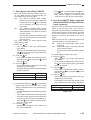
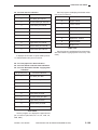
6. Auto Cassette Switching ON/OFF
• Auto Cassette Switching ON/OFF
This function sets Auto Paper Selection and Auto
Cassette Switching for each cassette.
(Auto Paper Switching automatically selects the
appropriate copy paper (cassette) according to
the size of the original and the selected copy ratio.
Auto Cassette Switching automatically supplies
paper from another paper cassette loaded with
the same paper size if the selected paper cassette
runs out during continuous copying.)
Auto Cassette Switching can be set individually
for each cassette.
ON:
Cassettes are selected automatically.
OFF: Cassettes are only selected manually.
• The initial setting for Auto Cassette Switching is
ON.
key.
1) Press the
• “U01” appears in the Copy quantity/Copy
ratio display.
• Once you set the Additional Functions mode,
the key turns red and copying operations
cannot be initiated.
Aditional
Function
1–22
COPYRIGHT © 1998 CANON INC.
2) Press the 4 key.
• If you make a mistake while entering a value,
press either the START key or press the C
key and then the 4 key.
3) Press the
key.
• The Paper Supply/Jam Location indicator for
the upper cassette of the copier main unit light
continuously. The current setting for the upper
cassette of the copier main unit is displayed in
the Copy quantity/Copy ratio display.
The ON/OFF settings for the Auto Cassette
Switching function are as shown in the table
below.
OK
Auto Cassette Switching
Settings
ON
–1
OFF
–0
Table 1-408
4) Press the Number keys ( 1 , 0 ) to select Auto
Cassette Switching ON or OFF for the top
cassette in the copier main unit. The current
setting is displayed in the Copy quantity/Copy
ratio display.
• The initial setting for Auto Cassette Selection
is ON.
• If coloured paper or another type of special
copy stock of the same size is loaded in one
of the paper cassettes, then you may not want
the copier to automatically switch the paper
cassette. Select OFF.
• If you make a mistake while entering a value,
enter the correct value and it will replace the
incorrect one that was previously entered, or
press the C key and after the display clears,
enter the correct value.
key.
5) Press the
• The bottom cassette of the copier main unit
lights.
6) Press the Number keys ( 1 , 0 ) to select Auto
Cassette Switching ON or OFF for the bottom
cassette in the copier main unit.
• Repeat steps ➎ and ➏ to select the Auto
Cassette Switching for all of the cassettes.
• This procedure is the same when the copier
is equipped with the optional Cassette Feeding Module or Cassette Pedestal.
key.
7) Press the
• Auto Cassette Switching ON or OFF is set
and “U04” is displayed.
key is pressed before the key is
• If the
pressed, the changed Auto Cassette Switching
ON/OFF setting is cleared and the copier
returns to the normal copying mode.
OK
OK
CANON NP6621 REV.0 FEB. 1998 PRINTED IN JAPAN (IMPRIME AU JAPON)
GENERAL DESCRIPTION
7. Stack Bypass Size Entry ON/OFF
• When making two-sided and overlay copies, etc.
on copy paper placed in the stack bypass, you
must specify the size of the paper.
OFF: The “SELECT PAPER SIZE” display
flashes and the stack bypass paper size
key is pressed
is specified when the
only if necessary according to the set
copy mode.
ON:
The “SELECT PAPER SIZE” display
flashes and the stack bypass paper size
is specified when copy paper is placed in
the stack bypass.
Like the paper cassettes, the stack bypass
can also be selected during Auto Paper
and Auto Zoom.
• The initial setting for Stack Bypass Size
Specification is OFF.
key.
1) Press the
• “U01” appears in the Copy quantity/Copy
ratio display.
• Once you set the Additional Functions mode,
the key turns red and copying operations
cannot be initiated.
2) Press the 5 key.
• If you make a mistake while entering a value,
press either the 5 key or press the C key and
then the 5 key.
3) Press the
key.
• The current setting is displayed in the Copy
quantity/Copy ratio display.
• The Stack Bypass Size Entry ON/OFF settings
appear as follows.
Aditional
Function
OK
key is pressed before the key is
• If the
pressed, the changed Stack Bypass Size
Entry ON/OFF setting is cleared and the
copier returns to the normal copying mode.
OK
8. Auto Sort ON/OFF (When equipped
with the ADF/RDF and Stapler Sorter/
Sorter (options))
• Auto Sort is a function which automatically outputs
copies in the Non-Sort mode if your copier is
equipped with the ADF/RDF and Stapler Sorter/
Sorter (options) and the original is only one sheet
or one set of copies, or in the Sort mode if the
original is more than one sheet or one set of
copies.
When Auto Sort is OFF, copies are output in the
mode indicated by the Sorter indicator.
ON:
Copies are automatically output in the
Sort mode
OFF: Copies are output in the mode indicated
by the Sorter indicator.
The Sort mode is selected with the Sorter
key.
• The initial setting for Auto Sort is ON.
key.
1) Press the
• “U01” appears in the Copy quantity/Copy
ratio display.
• Once you set the Additional Functions mode,
the key turns red and copying operations
cannot be initiated.
2) Press the 6 key.
• If you make a mistake while entering a value,
press either the key or press the C key and
then the key.
key.
3) Press the
• The current setting is displayed in the Copy
quantity/Copy ratio display.
The settings for the Auto Sort appear in the
Copy quantity/Copy ratio display as follows:
Aditional
Function
6
6
Stack Bypass Size Entry ON/OFF
Settings
ON
–1
OFF
–0
OK
Table 1-409
4) Press the Number keys ( 1 , 0 ) to select stack
bypass Size Entry ON or OFF. The current
setting is displayed in the Copy quantity/Copy
ratio display.
• The initial setting for Stack Bypass Size Entry
is OFF.
• If you make a mistake while entering a value,
enter the correct value and it will replace the
incorrect one that was previously entered, or
press the C key and after the display clears,
enter the correct value.
key.
5) Press the
• Stack Bypass Size Entry ON or OFF is set
and “U5” is displayed.
Auto Sort
Settings
ON
–1
OFF
–0
Table 1-410
OK
COPYRIGHT © 1998 CANON INC.
CANON NP6621 REV.0 FEB. 1998 PRINTED IN JAPAN (IMPRIME AU JAPON)
1–23
GENERAL DESCRIPTION
4) Press the Number keys ( 1 , 0 ) to select Auto
Sort ON/OFF.
• The settings are displayed in the Copy
quantity/Copy ratio display.
• The initial setting for Auto Sort is ON.
• If you make a mistake while entering a value,
enter the correct value and it will replace the
incorrect one that was previously entered, or
press the C key and after the display clears,
enter the correct value.
key.
5) Press the
• Auto Sort ON or OFF is set and “U06” is
displayed.
key is pressed before the key is
• If the
pressed, the changed setting is cleared and
the copier returns to the normal copying mode.
OK
OK
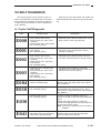
10. Standard Copy Settings (Store/Initialize)
• The Standard Copy Settings which are set when
the
key is pressed can be changed and
stored as desired. In addition, the changed
Standard Copy Settings can be returned to initial
settings.
• The factory-preset (initial) standard copy settings
are as follows:
• Copy exposure
Automatic
Exposure
Control
• Paper selection
Auto Paper Selection
• Number of copies 1
• Copy output
Non-Sort
• Copying
1 → 1 Sided
• Copy ratio
Direct (100%)
key.
1) Press the
• “U01” appears in the Copy quantity/Copy
ratio display.
• Once you set the Additional Functions mode,
the key turns red and copying operations
cannot be initiated.
2) Press the 8 key.
• If you make a mistake while entering a value,
press either the 8 key or press the C key and
then the 8 key.
3) Press the
key.
• “–1” is displayed in the Copy quantity/Copy
Ratio display.
• The settings for Standard Copy Seeting Store/
Initialize are as shown in the table below.
Aditional
Function
9. Feeder Cleaning (When equipped
with the ADF/RDF (options))
• This function automatically cleans the ADF/RDF
(option) Feeding Roller when it becomes dirty
with pencil lead, etc. If your originals have black
streaks or appear dirty after feeding them into the
ADF/RDF, perform Feeder Cleaning. Cleaning is
accomplished by repeated feeding of blank
originals (copy sheets) through the ADF/RDF.
key.
1) Press the
• “U01” appears in the Copy quantity/Copy
ratio display.
• Once you set the Additional Functions mode,
the key turns red and copying operations
cannot be initiated.
2) Press the 7 key.
• If you make a mistake while entering a value,
press either the key or press the C key and
then re-enter the value.
3) Place about 10 blank A4-size originals (copy
sheets) in the ADF/RDF. Then, press the
key.
• Feeder Cleaning begins.
• To stop Feeder Cleaning before it is comkey.
pleted, press the
• To use this function, your copier must be
equipped with the ADF/RDF.
• Use blank A4-size originals to perform
cleaning.
• Dirt will be picked up on the blank originals
used for cleaning.
• During feeder cleaning, “U08” flashes in the
copy quantity display. After feeder cleaning is
finished , “U08” stops flashing and lights.
Aditional
Function
OK
Standard Copy Setting Store/Initialize
Settings
Store
–1
Initialize
–0
7
1–24
COPYRIGHT © 1998 CANON INC.
Table 1-411
4) Press the Number keys ( 1 , 0 ) to select
Standard Copy Settings Store or Initialize.
• The settings are displayed in the Copy
quantity/Copy ratio display.
• If you make a mistake while entering a value,
enter the correct value and it will replace the
incorrect one that was previously entered, or
press the C key and after the display clears,
enter the correct value.
5) Press the
key.
• The Standard Copy Settings are stored or
initialized and “U08” is displayed.
key is pressed before the key is
• If the
pressed, the changed settings for Standard
Copy Setting Store/Initialize are cleared and
the copier returns to the normal copying mode.
OK
OK
CANON NP6621 REV.0 FEB. 1998 PRINTED IN JAPAN (IMPRIME AU JAPON)
GENERAL DESCRIPTION
11. Initializing User Mode
• The settings that were changed in the Additional
Functions mode can be restored to their initial
settings.
key.
1) Press the
• “U01” appears in the Copy quantity/Copy
ratio display.
• Once you set the Additional Functions mode,
the key turns red and copying operations
cannot be initiated.
2) Press the 0 key twice.
• If you make a mistake while entering a value,
press either the key twice or press the C key
and then press the key twice.
key.
3) Press the
• “–1” is displayed in the Copy quantity/Copy
ratio display.
4) Press the 0 key.
• “–0” is displayed in the Copy quantity/Copy
ratio display.
• If you make a mistake while entering a value,
enter the correct value and it will replace the
incorrect one that was previously entered, or
press the C key and after the display clears,
enter the correct value.
5) Press the
key.
• The Additional Functions are initialized and
“U00” is displayed.
Aditional
Function
0
0
OK
OK
Note:
key is pressed before the
key is
If the
pressed, the Additional Functions are not initialized, and the copier will return to the normal
copying mode.
OK
COPYRIGHT © 1998 CANON INC.
CANON NP6621 REV.0 FEB. 1998 PRINTED IN JAPAN (IMPRIME AU JAPON)
1–25
GENERAL DESCRIPTION
V. WARNINGS AND
ACTIONS
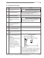
A. Jam Indicator
1. When q Flashes on the Control Panel
1) Open the front door.
Drum
Figure 1-504
Figure 1-501
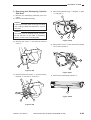
2) Lift the green lever on the left side to open the
top of the main unit.
Figure 1-502
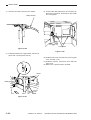
3) Slowly remove any jammed paper, taking care
not to tear it.
• If a paper jam occurs in a location similar to
that shown in the picture to the lower, slowly
turn the green knob in the direction of the
arrows and remove the jammed paper.
!
Fixing assembly
Knob
Caution:
1. The area surrounding the fixing assembly
gets hot during copying. When clearing a
paper jam in that area, be careful. Do not
touch any part of the fixing assembly,
because you could burn yourself.
2. When removing jammed paper or otherwise
inspecting the inside of the copier, do not
allow necklaces, bracelets or other metal
objects to touch the inside of the copier, as
this may result in burns or electrical shock.
3. When removing copy paper which has
become jammed from inside the copier,
take care not to allow the toner on the
jammed copy paper to come into contact
with your hands or clothing, as this will dirty
your hands and clothing. If they become
dirty, wash them immediately with cold
water. Washing with warm water will set the
toner and make it impossible to remove
toner stains.
4. When removing copy paper which has
become jammed from inside the copier,
remove the jammed copy paper gently to
prevent the toner on the paper from
scattering and entering your eyes or mouth.
If toner enters your eyes or mouth, wash
immediately with cold water and consult a
physician.
Notes:
1. If the jammed paper tears while removing it,
be sure to remove any pieces remaining
inside the copier.
2. Do not touch the purple colored surface of
the drum; doing so will adversely affect the
copy quality.
Figure 1-503
1–26
COPYRIGHT © 1998 CANON INC.
CANON NP6621 REV.0 FEB. 1998 PRINTED IN JAPAN (IMPRIME AU JAPON)
GENERAL DESCRIPTION
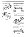
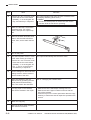
• If a paper jam occurs in a location similar to
that shown in the picture to the lower, slowly
pull the paper out in the direction of the
arrows, taking care not to tear it.
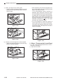
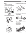
4) Gently close the top of the main unit.
Figure 1-509
Figure 1-505
5) If a paper jam occurs while using the stack
bypass, remove paper placed there and then
gently remove any paper jammed in the stack
bypass so that it does not tear.
Figure 1-506
Figure 1-510
• If you cannot find the jammed paper, lift the
lever as shown in the picture. If paper is
jammed here, gently remove the paper so
that it does not tear.
6) Close the stack bypass, then open the right
door of the copier main unit cassette.
Lever
Figure 1-511
Figure 1-507
Figure 1-508
COPYRIGHT © 1998 CANON INC.
CANON NP6621 REV.0 FEB. 1998 PRINTED IN JAPAN (IMPRIME AU JAPON)
1–27
GENERAL DESCRIPTION
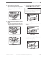
7) Place your finger on the inner guide.
• Push the inner guide down towards you and
gently pull out any jammed paper so that it
does not tear.
Figure 1-512
• After inspecting all areas that appeared on
the control panel, and removing all jammed
paper, close the front door.
If the Sorter/Stapler Sorter (options) is
attached, after closing the main unit, return
the Sorter/Stapler Sorter to its original position.
If a paper jam occurred while using the ADF/
RDF (options), after clearing the paper jam,
place the first page of the original back in the
key. The copier
ADF/RDF and press the
will make the remaining copies.
• It is not necessary to enter the number of
copies again after removing jammed paper.
The copier automatically senses the number
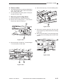
of jammed sheets, and adjusts the number of
copies accordingly.
Figure 1-513
Figure 1-515
8) Securely close the right door of the cassette.
• When using the stack bypass, place the copy
paper in the stack bypass.
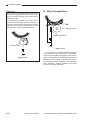
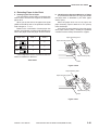
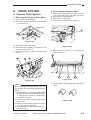
2. When w Flashes on the Control Panel
• If q and w both flash at the same time, check q
first before checking w.
1) Open the front door.
Figure 1-514
Figure 1-516
1–28
COPYRIGHT © 1998 CANON INC.
CANON NP6621 REV.0 FEB. 1998 PRINTED IN JAPAN (IMPRIME AU JAPON)
GENERAL DESCRIPTION
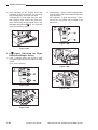
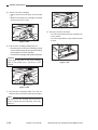
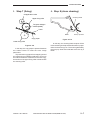
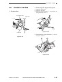
2) Open the right door of the cassette.
• Place your finger on the green finger grip and
pull open the inner guide for the copier main
unit cassette. If the Cassette Feeding Module
or Paper Deck (options) is attached, open
both doors.
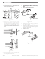
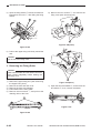
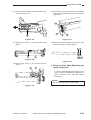
4) If you cannot clear the paper jam after following
steps ➊ and ➋, then pull out the cassette.
Note:
If you cannot see the cassette because the
front door is in the way, close the front door.
After you have cleared the paper jam, open and
close the front door once again.
Figure 1-517
3) Gently pull out any jammed paper so that it does
not tear.
• If a paper jam is located in the Paper Deck
(options), then pull the green grip and pull out
any jammed paper.
Figure 1-518
Figure 1-520
5) Remove any paper that is sticking out of the
cassette.
Figure 1-521
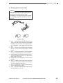
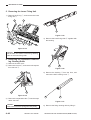
6) Return the cassette to its original position and
securely close the inner guide and right door for
the copier main unit cassette, or the right door
of the Paper Deck (options).
Figure 1-519
Figure 1-522
COPYRIGHT © 1998 CANON INC.
CANON NP6621 REV.0 FEB. 1998 PRINTED IN JAPAN (IMPRIME AU JAPON)
1–29
GENERAL DESCRIPTION
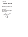
7) After inspecting all jam location areas that
appeared on the control panel, and removing
any jammed paper, close the front door.
If a paper jam occurred while using the ADF/
RDF (options), after clearing the paper jam,
place the first page of the original back in the
key. The copier will
ADF/DRF and press the
make the remaining copies.
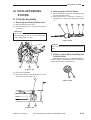
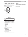
2) If the indicator e lights, close the Stapler Sorter
cover and return the Sorter/Stapler Sorter to its
original position.
If the indicator e lights after making copies,
remove any copy paper that is located in the
Sorter bins.
4
3
1
2
2
Figure 1-526
Figure 1-523
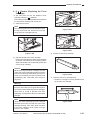
3. If
Lights (Checking the Right
Door/Sorter/Stapler Sorter)
1) If the w indicator lights, then check to make
sure that the right door of the cassette is securely
closed.
If not, close it securely.
Figure 1-527
4
3
1
2
2
Figure 1-524
Figure 1-528
Figure 1-525
1–30
COPYRIGHT © 1998 CANON INC.
CANON NP6621 REV.0 FEB. 1998 PRINTED IN JAPAN (IMPRIME AU JAPON)
GENERAL DESCRIPTION
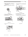
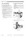
4. If
Flashes (Replacing the Toner
Cartridge)
• If the toner has run low, the Replace Toner
Cartridge indicator ( ) will flash.
Follow the procedure described below and replace
the used toner cartridge with a new one.
1) Open the front door.
Note:
Do not lift the green lever on the left side to open
the top of the main unit. Some toner may spill
out of the toner cartridge opening.
Lever
Figure 1-530
Figure 1-531
Figure 1-529
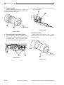
3) Prepare a new toner cartridge.
2) Grip the handle of the toner cartridge.
Push in the cartridge lever and turn the cartridge
clockwise until it reaches a horizontal position.
When the handle is at a horizontal position pull
out the toner cartridge.
Caution:
When removing used toner cartridges from the
copier, remove the cartridges carefully to prevent
toner from scattering and entering your eyes or
mouth. If toner enters your eyes or mouth, wash
immediately with cold water and consult a
physician.
Figure 1-532
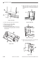
4) Hold the new toner cartridge level.
• Shake the cartridge to evenly distribute the
toner within the cartridge.
Warning:
Do not throw toner cartridges into open fires, as
this may cause the toner to ignite and result in
burns or fire. When disposing of toner cartridges,
place them in a bag to prevent toner from
spattering, and dispose of them as unburnable
garbage.
Note:
Take care when replacing the toner cartridge
because some toner may spill out of the toner
cartridge opening. Also, some toner may stick
to the toner cartridge, so be careful not to get
toner on your clothes.
COPYRIGHT © 1998 CANON INC.
Figure 1-533
CANON NP6621 REV.0 FEB. 1998 PRINTED IN JAPAN (IMPRIME AU JAPON)
1–31
GENERAL DESCRIPTION
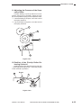
5) Set the new toner cartridge.
• Gently insert it into the copier as far as it will
go.
• Make sure that the toner cartridge is inserted
all the way into the copier.
Figure 1-536
8) Securely close the front door.
• You cannot close the front door until the main
unit is closed.
• You cannot operate the copier if the front door
is open.
Figure 1-534
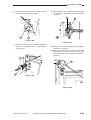
6) Pull the toner cartridge sealing tape off.
• Pressing down on the toner cartridge, grip the
orange sealing tape tab and pull the sealing
tape straight out of the cartridge.
• Pull the toner cartridge sealing tape off straight.
Caution:
Some toner may stick to the toner cartridge
seal, so be careful not to get toner on your
clothes.
Figure 1-537
Sealing tape
Figure 1-535
7) Grip the toner cartridge handle. Turn the cartridge counter-clockwise until it locks into place.
Note:
Be sure to turn the cartridge until it locks into
place. If it does not lock into place, toner may
spill out.
1–32
COPYRIGHT © 1998 CANON INC.
CANON NP6621 REV.0 FEB. 1998 PRINTED IN JAPAN (IMPRIME AU JAPON)
GENERAL DESCRIPTION
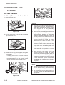
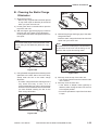
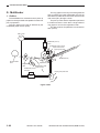
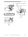
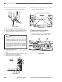
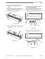
B. Cleaning the Static Charge
Eliminator
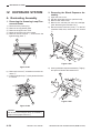
1) Open the front door.
• Remove any originals that have been placed
on top of the copier so that they do not fall off
when you open the main unit.
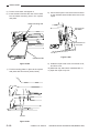
2) Lift the green lever on the left side to open the
top of the main unit.
3) With two fingers, grip the finger grip located on
the front part of the static charge eliminator.
Lift and pull out the static charge eliminator from
the copier.
Note:
Do not touch the purple coloured surface of the
drum; doing so will adversely affect the copy
quality.
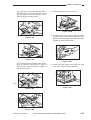
Figure1-540
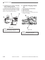
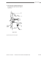
5) With two fingers grip the finger grip of the static
charge eliminator.
Insert the static charge eliminator back into the
copier until you hear a click.
Note:
Be careful not to touch the purple-colored surface
on the drum of the main unit as doing so will
prevent clear copies from being made.
Drum
Figure1-538
4) Using the static charge eliminator cleaning brush
(attached to the back side of the front door),
sweep clean the slot on the static charge
eliminator.
• The static charge eliminator cleaning brush is
very small and easy to lose, so it is
recommended that you return it to its storage
location on the back side of the front door after
you have finished cleaning the slot on the
static charge eliminator.
Figure1-541
6) Securely close the top of the main unit.
• You cannot close the front door until the main
unit is closed.
7) Securely close the front door.
• If the Sorter or Stapler Sorter (options) is
attached, after closing the main unit, return it
to its original position.
• You cannot operate the copier if the front door
is open.
Cleaning brush
Figure1-539
COPYRIGHT © 1998 CANON INC.
CANON NP6621 REV.0 FEB. 1998 PRINTED IN JAPAN (IMPRIME AU JAPON)
1–33
GENERAL DESCRIPTION
VI. ROUTINE CLEANING
Clean the following parts once a week or whenever copies appear dirty.
Warning:
1. When cleaning the copier, first turn OFF the
power switch and unplug the power plug.
Failure to observe these items may result in
fire or electrical shock.
2. Clean the copier using a firmly wrung-out
cloth dampened with a mild cleansing
detergent. Do not use alcohol, benzene,
paint thinner, or other inflammable
substances. If inflammable substances
come into contact with a high-voltage area
inside the copier, it may result in fire or
electrical shock.
1. Platen glass
• Clean the platen glass with a cloth dampened
with water or a mild cleaning agent. Then,
wipe with a dry cloth.
2. Underside of the platen glass cover
• Clean the underside of the platen glass cover
with a cloth dampened with water or a mild
cleaning agent. Then, wipe with a dry cloth.
3. Bottom of the ADF/RDF (Accessory)
• Move the feeding belt with your hand as you
wipe it with a cloth dampened with water or a
mild cleaning agent. Then, wipe with a dry
cloth.
1–34
COPYRIGHT © 1998 CANON INC.
CANON NP6621 REV.0 FEB. 1998 PRINTED IN JAPAN (IMPRIME AU JAPON)
CHAPTER 2
COPYING PROCESS
I.
IMAGE FORMATION ................................ 2-1
A. Outline ................................................. 2-1
B. Latent Static Image Formation Block .. 2-2
C. Step 1 (pre-exposure) ......................... 2-3
D. Step 2 (primary charging) .................... 2-3
E. Step 3 (image exposure) ..................... 2-4
F. Step 4 (development) .......................... 2-4
COPYRIGHT © 1998 CANON INC.
G. Step 5 (transfer) .................................. 2-5
H. Step 6 (separation) .............................. 2-6
I. Step 7 (fixing) ...................................... 2-7
J. Step 8 (drum cleaning) ........................ 2-7
II. AUXILIARY PROCESS ............................. 2-8
A. Blank Exposure ................................... 2-8
CANON NP6621 REV.0 FEB. 1998 PRINTED IN JAPAN (IMPRIME AU JAPON)
COPYRIGHT © 1998 CANON INC.
CANON NP6621 REV.0 FEB. 1998 PRINTED IN JAPAN (IMPRIME AU JAPON)
COPYING PROCESS
I. IMAGE FORMATION
A. Outline
Copyboard glass
Scanning lamp
Lens
Primary corona roller
Pre-exposure lamp
Cleanig roller
Fixing roller
Developing cylinder
Cleaning assembly
Copy paper
Transfer roller
Static eliminator
Pressure roller
Copy paper
Figure 2-101
Static latent image formation block
Image exposure
Primary
Pre-exposure
Development
Drum
Transfer
Delivery
Manual feeding
Separation
Fixing
Registration
Cassette
flow of copy paper
rotation of drum
Figure 2-102
COPYRIGHT © 1998 CANON INC.
CANON NP6621 REV.0 FEB. 1998 PRINTED IN JAPAN (IMPRIME AU JAPON)
2–1
COPYING PROCESS
The copier forms images through the following
steps, and each of the steps functions as described
below.
B. Latent Static Image
Formation Block
step 1
step 2
step 3
step 4
step 5
step 6
step 7
step 8
The block consists of three steps; at the end of
the block, areas of the drum corresponding to the
black areas of the original are left with negative
charges and the areas of the drum corresponding to
the white areas of the original are rid of negative
charges.
The images formed on the drum by the presence and absence of negative charges are not
visible to the human eye and, therefore, the term
latent static images.
The photosensitive drum consists of a
photoconducting layer on the outside and an aluminum base on the inside; the photoconducting layer
is made of organic photoconductor (OPC), and the
aluminum conductor is a photoconductor.
Time (t)
Surface potential (V)
pre-exposure
primary charging (negative DC)
image exposure
development (AC and negative DC bias)
transfer (negative DC)
separation (curvature + static eliminator)
fixing
drum cleaning
Light area
-500
Photo conducting layer
Base
Figure 2-103
-1000
Primary
corona
charg
Pre-ex ing
posure (step 2)
(step1)
Dark area
Image exposure
(step 3)
Figure 2-104
2–2
COPYRIGHT © 1998 CANON INC.
CANON NP6621 REV.0 FEB. 1998 PRINTED IN JAPAN (IMPRIME AU JAPON)
COPYING PROCESS
,,,,
|||
yyyy
zzz
{{{{
,,,,
yyyy
zzz
{{{{
|||
,,,,
yyyy
zzz
{{{{
|||
{{{{
|||
C. Step 1 (pre-exposure)
D. Step 2 (primary charging)
Pre-exposure lamp
Primary charging roller
Figure 2-105
Figure 2-106
Before primary charging takes place, the light of
the pre-exposure lamp is directed to the photosensitive drum to eliminate the residual charges on the
drum, thereby preventing uneven density.
The copier uses what is termed primary charging, in which a charging roller made of conducting
material directly charges the photosensitive drum.
Compared to the conventional corona charging
method, direct charging provides such advantages
as a low application voltage and virtual absence of
ozone.
The primary charging roller is a special roller
and possesses different characteristics from the
transfer roller.
COPYRIGHT © 1998 CANON INC.
CANON NP6621 REV.0 FEB. 1998 PRINTED IN JAPAN (IMPRIME AU JAPON)
2–3
COPYING PROCESS
E. Step 3 (image exposure)
Optical image
F. Step 4 (development)
Toner
Blade
Cylinder
Magnet
Dark
Developing
cylinder
Light area
Figure 2-108
Figure 2-107
In this step, the optical image of an original is
projected on the photosensitive drum to neutralize
the charges in the light areas.
As shown in Figure 2-108, the developing assembly consists of a fixed magnet, a cylinder that
rotates around the magnet, and a rubber blade.
The toner is a one-component toner whose
main ingredient is magnetic resins.
The toner has insulating characteristics and
becomes positively charged by friction against the
rubber blade, which remains in contact under pressure with the cylinder; the toner is evened out to
form a thin layer on the cylinder owing to the
elasticity of the rubber.
Toner
Blade
Magnet
Magnet
Figure 2-109
2–4
COPYRIGHT © 1998 CANON INC.
CANON NP6621 REV.0 FEB. 1998 PRINTED IN JAPAN (IMPRIME AU JAPON)
COPYING PROCESS
An AC bias and DC bias (negative component)
are applied simultaneously* to the developing cylinder and the blade.
* Termed development bias, whose negative component is larger than that of the positive component.
G. Step 5 (transfer)
Positive
component
0V
Transfer
roller
Transfer
guide plates
Negative
component
DC bias
Figure 2-110
During copying operation, the drum surface
potential and development bias (at time of positive
component) draw toner to the photosensitive drum
to turn the latent static image into a visible image.
The excess toner is drawn away from the photosensitive drum by the work of the drum surface potential
and the developing bias (at time of negative component).
The AC bias (frequency, in particular) mainly
affects gradation; a lower frequency improves the
gradation, but tends to result in fogging. The DC
bias relates to copy density and fogging; a higher
bias, that is closer to 0 V, darkens the image but in
turn could lead to fogging.
COPYRIGHT © 1998 CANON INC.
Figure 2-111
The transfer roller deposits negative charges
on the back of copy paper to attract toner from the
drum surface to the copy paper.
The copier uses a roller transfer method, which
requires a lower transfer voltage compared to corona transfer methods and generates virtually no
ozone.
To prevent transfer failure or soiling of the back
of copy paper, the transfer guide is grounded
through a varistor.
Reference:
If the transfer guide was grounded, the charges
that should be on the back of copy paper would
escape, causing transfer failure; by the same
token, if the transfer guide is not grounded at
all, it would become charged and soiled with
deposits of toner, soiling the back of copy
paper.
CANON NP6621 REV.0 FEB. 1998 PRINTED IN JAPAN (IMPRIME AU JAPON)
2–5
COPYING PROCESS
Reference:
If the image on the photosensitive drum fails to
transfer to copy paper because of a jam or the
like, the transfer charging roller could become
soiled with toner.
To prevent such a problem, the copier uses a
positive transfer voltage when the scanner is
moving in reverse or during post rotation, thereby
returning the positively charged toner on the
transfer roller to the photosensitive drum.
H. Step 6 (separation)
Transfer roller
Static eliminator
Transfer roller
Figure 2-113
Figure 2-112
2–6
COPYRIGHT © 1998 CANON INC.
The copier uses a curvature separation method,
which separates copy paper from the photosensitive drum by the rigidity of the paper. However, thin
paper could at times fail to separate from the drum
because of its low rigidity. To prevent such a problem, a positive charge is applied to the separation
static eliminator, thereby weakening the static
attraction for better separation.
CANON NP6621 REV.0 FEB. 1998 PRINTED IN JAPAN (IMPRIME AU JAPON)
COPYING PROCESS
I. Step 7 (fixing)
J. Step 8 (drum cleaning)
Oil application roller
Cleaning blade
Upper fixing roller
Tungsten-halogen
heater (900W)
Toner
Blade
Scoop-up sheet
Copy paper
Figure 2-115
Lower fixing roller
Figure 2-114
In this step, the copy paper is pressed between
two heated rollers to make the toner image
permanent.
To prevent the copy paper from wrapping around
the roller and toner offsetting (adhesion of toner to
the roller and transfer of the toner to the next copy),
the surface of the upper fixing roller is cleaned with
the cleaning roller.
COPYRIGHT © 1998 CANON INC.
In this step, the cleaning blade scrapes off the
toner remaining on the photosensitive drum in preparation for the next copy run. The toner is gathered by
the scoop-up sheet and collected at the rear by a
blade.
CANON NP6621 REV.0 FEB. 1998 PRINTED IN JAPAN (IMPRIME AU JAPON)
2–7
COPYING PROCESS
II. AUXILIARY PROCESS
A. Blank Exposure
Blank exposure is executed to remove the drum
surface potential of the non-image area that occurs
as a result of the difference among copy sizes or
when making copies in Reduce mode.
The light from the pre-exposure lamp is reflected by the reflecting plate and directed to the
photosensitive drum.
The non-image area between sheets of copy
paper is created by reflecting the light from the preexposure lamp by a separate reflecting plate,
exposing the whole area.
Pre-exposure lamp Blank exposure
light path
Reflecting
plates
No. 6 mirror
Shutter
Reflecting plate
Blank exposure light path
(for area between sheets)
Pre-exposure
light path
Photosensitive drum
Figure 2-201
2–8
COPYRIGHT © 1998 CANON INC.
CANON NP6621 REV.0 FEB. 1998 PRINTED IN JAPAN (IMPRIME AU JAPON)
CHAPTER 3
OPERATIONS AND TIMING
In outline diagrams,
represents mechanical drive paths, and
indicates electrical
signal paths.
Signals in digital circuits are identified as ‘1’ for High and ‘0’ for Low. The voltage of signals,
however, depends on the circuit.
Nearly all operations of the product are controlled by a microprocessor; the internal workings
of the processor are not relevant to the service person’s work and, therefore, are left out of the
discussions. By the same token, no repairs are prescribed for the PCBs at the user’s premises; for
this reason, PCBs are discussed by means of block diagrams rather than circuit diagrams.
For the purpose of explanation, discussions are divided into the following: from sensors to main
PCB input ports; from main output ports to loads; and minor control circuits and functions.
I.
BASIC OPERATIONS ............................... 3-1
A. Functional Construction ....................... 3-1
B. Outline of Electrical Circuitry ............... 3-2
C. Inputs to the DC Controller .................. 3-3
D. Outputs from the DC Controller ........... 3-8
E. Inputs to and Outputs from the Cassette
Feeding Module-B2 Driver PCB ........ 3-13
F. Inputs to and Outputs from the Cassette
Feeding Module-A2 Driver PCB ........ 3-14
G. Inputs to and Outputs from the Cassette
Feeding Unit-K1 Driver PCB ............. 3-16
H. Main Motor Control Circuit ................. 3-21
I. Basic Sequence of Operations
(2 copies, continuous, AE) ................ 3-22
J. Original Size Detecton Control .......... 3-23
II. EXPOSURE SYSTEM ............................. 3-27
A. Varying the Reproduction Ratio ........ 3-27
B. Lens Drive System ............................ 3-27
C. Scanner Drive System ....................... 3-31
D. Operations of the Scanner in Page
Separation Mode ............................... 3-34
III. IMAGE FORMATION SYSTEM .............. 3-35
A. Outline ............................................... 3-35
B. Sequence of Operations
(image formation system) .................. 3-36
COPYRIGHT © 1998 CANON INC.
C. Controlling the Scanning Lamp ......... 3-37
D. Controlling the Primary Charging
Roller ................................................. 3-38
E. Controlling the Transfer Roller Bias .... 3-41
F. Controlling the Static Eliminator
Bias .................................................... 3-44
G. Controlling the Developing Bias ........ 3-46
H. Copy Density Automatic Control ....... 3-48
I. Developing/Cleaning Assembly ........ 3-50
J. Blank Exposure Control ..................... 3-53
K. Primary Charging Roller Cleaning
Control ............................................... 3-55
L. Transfer Roller Locking/Releasing
Control ............................................... 3-56
IV. PICK-UP/FEEDING SYSTEM ................. 3-57
A. Pick-Up from the Machine ................. 3-57
B. Making Two-Sided Copies (1copy) ... 3-61
C. Duplexing Unit ................................... 3-63
D. Pick-Up from the Cassette Feeding
Module-A2 ......................................... 3-72
E. Pick-Up from the Cassette Feeding
Unit-K1 ............................................... 3-74
F. Paper Deck Pedestal-K1 ................... 3-76
G. Multifeeder ......................................... 3-82
H. Identifying the Size of the Cassette ... 3-85
CANON NP6621 REV.0 FEB. 1998 PRINTED IN JAPAN (IMPRIME AU JAPON)
I. Fixing/Delivery Assembly .................. 3-87
J. Detecting Jams .................................. 3-92
V. POWER SUPPLY .................................. 3-101
A. Outline of Power Distribution ........... 3-101
B. Power Supply Circuitry .................... 3-102
C. Detecting Errors on the Power Supply
PCB ................................................. 3-103
D. Protection Mechanisms for the Power
Supply Circuit .................................. 3-104
VI. SERVICE MODE ................................... 3-105
A. Outline ............................................. 3-105
B. Using Service Mode ........................ 3-105
C. Control Display Mode (‘1’) ............... 3-107
D. I/O Mode (‘2’) ................................... 3-110
COPYRIGHT © 1998 CANON INC.
E. Adjustment Mode (‘3’) ..................... 3-114
F. Operation/Inspection Mode (‘4’) ...... 3-117
G. Machine Settings Mode (‘5’) ............ 3-118
H. Counter Mode (‘6’) ........................... 3-120
VII. SELF DIAGNOSIS ................................. 3-121
A. Copier Self Diagnosis ...................... 3-121
B. Self Diagnosis on the Cassette Feeding
Unit .................................................. 3-124
C. RDF/ADF Self Diagnosis ................. 3-125
D. Sorter Self Diagnosis ....................... 3-126
VIII. STANDARDS AND ADJUSTMENTS .... 3-127
A. Electrical .......................................... 3-127
CANON NP6621 REV.0 FEB. 1998 PRINTED IN JAPAN (IMPRIME AU JAPON)
OPERATIONS AND TIMING
I. BASIC OPERATIONS
A. Functional Construction
The machine can be divided into four functional blocks: pick-up/feeding system, exposure system, image
formation system, and control system.
Control system
Control panel
Copyboard
Image formation
system
Primary corona
assembly
Drum
cleaning
assembly
Fixing
assembly
Tray
Illuminating
assembly
Optical
path
assembly
Control circuit
Developing
assembly
Photosensitive
drum
Separation
Exposure system
Transfer
Feeding
assembly
Pick-up
control
assembly
Manual feeding
assembly
Duplexing
unit
Cassette 1
Pick-up/feeding
system 1
Cassette 2
Cassette
Unit
Pick-up/feeding
system 3 (accessory)
Cassette
Unit
Cassette
Unit
Flow of high voltage/toner
Flow of paper
Flow of light
Flow of electrical signals
Figure 3-101
COPYRIGHT © 1998 CANON INC.
CANON NP6621 REV.0 FEB. 1998 PRINTED IN JAPAN (IMPRIME AU JAPON)
3–1
OPERATIONS AND TIMING
B. Outline of Electrical Circuitry
The machine’s most electrical mechanisms are
controlled by the microprocessor on its DC controller
PCB. The microprocessor reads the input signals
from the sensors and operation keys according to
DC controller PCB
its pre-programmed instructions and sends signals
to drive such loads as motors, solenoids, and lamps
as necessary.
The machine’s microprocessor is capable of
reading analog signals as well as digital signals
using its A/D converter.
Fixing roller
heater
Heater driver PCB
RDF (accessory)
Sorter (accessory)
Composite power supply
+5V
+24V
+34V
Q301
CPU
CPU
Scanning lamp
Sensor
Toner level
detection
Highvoltage
circuit
Q307
ROM
Developing cylinder
Bias PCB
AE sensor PCB
Transfer charging
Static eliminator
Primary charging
HV
Main thermistor
Sub thermistor
Q308
RAM
Main motor
driver PCB
LA
Control panel
Control card (accessory)
Motor
Q311
IPC
Main motor
Pre-exposure lamp
Scanner motor
Lens motor
Duplexing motor
Fan
Heat exhaust fan, Feeding fan,Scanner cooling fan
SL
Change solenoid
Multifeeder holding plate solenoid
Blanking shutter solenoid
Primary charging roller cleaning solenoid
Transfer charging roller release solenoid
Duplexing change solenoid
CL
Registration clutch
Duplexing registration clutch
Pick-up clutch 1, 2
Multifeeder pick-up clutch
(accessory)
Motor
Sensor
M1
Cassette unit motor
Paper deck motor
Cassette driver PCB/
Paper deck driver PCB
CL
Cassette pick-up clutch
Deck pick-up clutch
Figure 3-102
3–2
COPYRIGHT © 1998 CANON INC.
CANON NP6621 REV.0 FEB. 1998 PRINTED IN JAPAN (IMPRIME AU JAPON)
OPERATIONS AND TIMING
C. Inputs to the DC Controller
1. Inputs to the DC Controller PCB (1/5)
DC controller PCB
Scanner home
position sensor
PS 1
5V
J 315B- 3
-4
SCHP
-5
PS 2
J 310A- 3
-2
-1
PS 3
J 315A- 6
-5
-4
PS 4
J 309- 7
-8
-9
PS 5
J 316- 11
- 10
-9
PS 6
J 316- 12
- 13
- 14
PS 7
J 316- 5
-4
-3
PS 8
J 309- 15
- 14
- 13
PS 10
J 309- 10
- 12
- 11
When the scanner is at home position, '1'.
(when the light-blocking plate is at PS1, '1')
5V
Lens home
position sensor
LHP
When the home position sensor detects lens, '1'.
(when the light-blocking plate is at PS2, '1')
5V
Blanking shutter
home position
sensor
BSHP
When the home position sensor detects the
blanking shutter, '1'.
(when the light-blocking plate is at PS3, '1')
5V
Cassette 1 paper
sensor
CPD1*
When paper is present in the cassette, '0'.
(when the light-blocking plate is not at PS4, '0')
5V
Multifeeder paper
sensor
MFPD*
When paper is present in the multifeeder assembly, '0'.
(when the light-blocking plate is not at PS5, '0')
5V
Registration
sensor
RPD
When PS6 detects paper, '1'.
(when the light blocking-plate is at PS6, '1')
5V
Separation
sensor
SPD*
When PS7 detects paper, '0'.
(when the light-blocking plate is not at PS 7, '0')
5V
Delivery sensor
DPD*
When PS8 does not detect paper, '0'.
(when the light-blocking plate is not at PS8, '0')
5V
Right door sensor
RDOP*
When the right door opens, '0'.
(when the light-blocking plate is not at PS10, '0')
Figure 3-103
COPYRIGHT © 1998 CANON INC.
CANON NP6621 REV.0 FEB. 1998 PRINTED IN JAPAN (IMPRIME AU JAPON)
3–3
OPERATIONS AND TIMING
2. Inputs to the DC Controller (2/5)
DC controller
5V
Copyboard cover
sensor
J 310A- 12
- 11
PS 11
- 10
CVOP
When the copyboard cover is open, '1'.
(when the light-blocking plate is at PS24)
5V
Vertical path roller 2
paper sensor
J 309- 6
-5
PS 12
VP2P
When PS12 detects paper, '1'.
-4
5V
Cassette 2 paper
sensor
J 309- 1
-3
PS 13
-2
CPD2*
When paper is present in the cassette, '0'.
(when the light-blocking plate is not at PS13, '0').
5V
Duplexing unit outlet
paper sensor
PS 14
J 325- 3
-2
-1
DUEX
When paper is present at the duplexing unit outlet, '1'.
5V
Duplexing unit inlet
paper sensor
PS 15
J 320- 1
-2
-3
DUIN
When paper is present at the duplexing unit inlet, '1'.
5V
J 314- 12
Vertical path roller 1
paper sensor
- 13
PS 16
- 14
VP1P
When paper is present at the vertical
path roller 1 sensor, '1'.
Figure 3-104
3–4
COPYRIGHT © 1998 CANON INC.
CANON NP6621 REV.0 FEB. 1998 PRINTED IN JAPAN (IMPRIME AU JAPON)
OPERATIONS AND TIMING
3. Inputs to the DC controller (3/5)
DC controller
Original size sensor 2
PS 21
J 310B- 8
-7
-9
SIZE2
Varies according to paper size.
5V
Original size sensor 1
PS 23
J 310B- 2
-1
-3
SIZE1
Varies according to paper size.
Figure 3-105
COPYRIGHT © 1998 CANON INC.
CANON NP6621 REV.0 FEB. 1998 PRINTED IN JAPAN (IMPRIME AU JAPON)
3–5
OPERATIONS AND TIMING
4. Inputs to the DC Controller PCB (4/5)
DC controller PCB
AE sensor
(1/2)
Cassette size
sensor 1
J 601
-1
-2
-3
-4
J 310A
-9
-8
-7
-6
J 651
-6
-5
-4
-3
-2
-1
J 318
-1
-2
-3
-4
-5
-6
J 801
J 802
J 803
Control panel
AE
AEREF
See p. 3-48.
CS
CSZ1
CSZ2
CSZ3
CSZ4
J 305
J 306
J 316B
-6
-7
-8
VR1
J 324A
-1
Main thermistor
(TH1)
See p. 3-85.
Keys and LEDs are wired in the form of
a matrix on the control panel PCB, and
the DC controller turns on the LEDs and
reads key inputs.
5V
MFPWD
Detects the width of the copy
paper stacked in the multifeeder.
TH1
-2
J 324A
-5
Sub thermistor
(TH2)
Cassette size
sensor 2
+24V
See p. 3-87.
TH2
-6
J 651
-6
-5
-4
-3
-2
-1
J 318
-7
-8
-9
- 10
- 11
- 12
CS
CSZ1
CSZ2
CSZ3
CSZ4
See p. 3-85.
Figure 3-106
3–6
COPYRIGHT © 1998 CANON INC.
CANON NP6621 REV.0 FEB. 1998 PRINTED IN JAPAN (IMPRIME AU JAPON)
OPERATIONS AND TIMING
5. Inputs to the DC Controller PCB (5/5)
Service switch PCB
DC controller PCB
Service switch
SRSW
When the switch turns on, '0'.
(starts service mode)
SW850
+5V
Density correction volume
J306-7
-8
CDC
Adjusts the developing DC bias
-9
VR850
AE sensor
adjustment volume
AEVR2
AEVR1
VR851
AE sensor (2/2)
Figure 3-107
COPYRIGHT © 1998 CANON INC.
CANON NP6621 REV.0 FEB. 1998 PRINTED IN JAPAN (IMPRIME AU JAPON)
3–7
OPERATIONS AND TIMING
D. Outputs from the DC Controller
1. Outputs from the DC Controller PCB (1/5)
Main switch
ON
Door switch
DC controller PCB
Cassette heater (H4)
Drum heater (H3)
Cassette heater (H5)
Composite power
supply PCB
+5V
Anti-condensation
switch (SW1)
RL101
EHTRL* When '0' RL101 turns ON.
(ON when the power is OFF)
Lens heater (R1)
When RL101 is ON and SW1
is ON, the heater (R1, R2)
turns ON.
Lens heater (R2)
24V
RL103
Fuse (FU1)
Fixing heater
(H1)
When '0', RL103 turns ON.
ACOFF (ON when the power is ON)
J319 +5V
–4
B
A
B
–1
HTON*
When the heater is ON, '0'.
HTRD
See p. 3-89.
–2
Fixing
heater
driver
A
–3
Fluorescent heater
switch (SW2)
Fluorescent lamp
heater (H2)
Fluorescent lamp
(LA1)
Primary charging roller
Developing cylinder
Transfer roller
Static eliminator
Scanning
lamp control
circuit
Microprocessor
Communicates with the composite
power supply PCB.
High-voltage
circuit
Toner level
detection
sensor
TEP*
When '0', "ADD TONER"
is indicated.
Antenna Sensor
Figure 3-108
3–8
COPYRIGHT © 1998 CANON INC.
CANON NP6621 REV.0 FEB. 1998 PRINTED IN JAPAN (IMPRIME AU JAPON)
OPERATIONS AND TIMING
2. Outputs from the DC Controller PCB (2/5)
DC controller PCB
+24V
Registration
clutch
J312A- 5
-6
CL1
RGCLD*
When '0', the registration clutch turns ON.
(registration roller rotates)
+24V
Cassette 1
pick-up clutch
J312A- 3
-4
CL2
PUCLD1*
When '0', the pick-up clutch turns ON.
(pick-up roller rotates)
+24V
Multifeeder
pick-up clutch
J312A- 1
-2
CL3
When '0', the pick-up clutch turns ON.
MFPUCLD* (multifeeder pick-up roller rotates)
+24V
Duplexing unit
outlet clutch
J312B- 9
- 10 CL4D*
CL4
When '0', the duplexing unit outlet
clutch (CL4) turns ON.
+24V
Cassette 2
pick-up clutch
J312B- 5
-6
CL5
CL5D*
When '0', the cassette 2 pick-up
clutch (CL5) turns ON.
+24V
Slip roller clutch
J312B- 3
-4
CL6
J501 J206
-1
-1
-2
-2
Main motor
J502
-4
-1
Main motor - 2
drive PCB - 3
M1
CL6D*
When '0', the Slip roller clutch (CL6) turns ON.
+36V
+5V
J312A
- 10
-7
MLOCK*
-8
MMD
-9
See p. 3-21.
J302
Scanner motor
See p. 3-33.
M2
J324B
Lens motor
See p. 3-29.
M3
J324A
Figure 3-109
COPYRIGHT © 1998 CANON INC.
CANON NP6621 REV.0 FEB. 1998 PRINTED IN JAPAN (IMPRIME AU JAPON)
3–9
OPERATIONS AND TIMING
3. Outputs from the DC Controller PCB (3/5)
DC controller PCB
Duplexing
unit motor
J326- 1
-2
-3
-4
-5
-6
M5
COM A
COM B
A
A*
B
B*
While M5 is rotating, alternates
between '1' and '0.
(pulse signal)
Figure 3-110
3–10
COPYRIGHT © 1998 CANON INC.
CANON NP6621 REV.0 FEB. 1998 PRINTED IN JAPAN (IMPRIME AU JAPON)
OPERATIONS AND TIMING
4. Outputs from the DC Controller PCB (4/5)
DC controller PCB
+24V
Change solenoid
SL1
J324B- 7
-8
SL2
J312B- 7
-8
SL3
J315A- 8
-7
SL4
J324A- 8
-7
SL5
J316- 2
-1
SL6
J324B- 3
-4
SL 8
J320- 5
-4
CHSLD*
When '1', the solenoid turns OFF.
(blanking shutter width control)
When '0', the solenoid turns ON.
(lens mount moved)
+24V
Multifeeder holding
plate solenoid
MFSLD*
When '0', the solenoid turns ON.
(holding plate released)
+24V
Blanking shutter
solenoid
BSSLD*
When '0', the solenoid turns ON.
(blanking shutter opened)
+24V
Primary charging roller
cleaning solenoid
PCLSLD*
When '0', the solenoid turns ON.
(cleaning pad locked)
+24V
Transfer charging roller
releasing solenoid
TRSLD*
When '0', the solenoid turns ON.
(transfer roller lowered)
24V
Oil application solenoid
SL6D*
When '0', the oil application
solenoid (SL6) turns ON.
(sensor drive)
24V
Paper deflecting
plate solenoid
SL8D*
When '0', the paper deflecting plate
solenoid (SL8) turns ON.
(duplexing unit inlet opened)
Figure 3-111
COPYRIGHT © 1998 CANON INC.
CANON NP6621 REV.0 FEB. 1998 PRINTED IN JAPAN (IMPRIME AU JAPON)
3–11
OPERATIONS AND TIMING
5. Outputs from the DC Controller PCB (5/5)
DC controller PCB
+24V
J 310A- 4
Scanner cooling fan
(FM2)
-5
When '0', the Scanner cooling fan turns ON.
FM2D
(Scanner cooling fan rotates)
+24V
J 315B- 2
Heat exhaust fan
(FM1)
-1
HEFD*
When '0', the heat exhaust fan turns ON.
(heat exhaust fan rotates)
+24V
J 314A- 7
Feeding fan
-8
(FM4)
Power supply
cooling fan
(FM3)
+24V
J12-4
-3 PSCFD Composite power
supply PCB
-2
J 401
-1
FDFD*
When '0', the feeding fan turns ON.
(feeding fan rotates)
J307
When '1', the power supply cooling fan turns ON.
J 315A
- 10
+24V
Pre-exposure
lamp
When '0', the pre-exposure lamp
turns ON.
-2
-9
J 315B
-9
Total copy counter
-8
PEXP*
+24V
TCNTD*
When changes from '0' to '0', the
count is incremented.
+5V
J 306A- 11
- 13
- 12
- 10
Control Card N
CCD*
When '0', the count is incremented.
CCDT*
When '0', the control card is present.
5V
J 311A- 7
-8
Remote
Diagnostic
-6
-5
-4
Device II
AST-CNTP*
When '0', a copy is counted.
AST-TXD
Transmission data (IPC communication)
AST-RXD
Reception data (IPC communication)
24V
-2
-3
Figure 3-112
3–12
COPYRIGHT © 1998 CANON INC.
CANON NP6621 REV.0 FEB. 1998 PRINTED IN JAPAN (IMPRIME AU JAPON)
OPERATIONS AND TIMING
E. Inputs to and Outputs from the Cassette Feeding Module-B2
Driver PCB
1. Inputs to and Outputs from the Cassette Feeding Module-B2 Driver PCB (1/1)
Cassette driver PCB
DC controller PCB
5V
J 110- 1
Cassette 3
vertical path
sensor
-3
PS1cu
C3VPD
-2
When PS1 detects paper, '1'.
(when the light-blocking plate
is at PS1cu, '1')
5V
J 110- 4
Cassette 3
paper sensor
-6
PS2cu
J 651
-6
-5
-4
-3
-2
-1
Cassette 3
size detection
C3PD
-5
J 110
-7
-8
-9
- 10
- 11
- 12
When paper is present in the
cassette, '0'.
(when the light-blocking plate
is not at PS2cu, '0')
CS2
C2SZ1
C2SZ2
C2SZ3
C2SZ4
See p. 3-85.
+24V
Cassette 3
pick-up clutch
Cassette
unit motor
CL1cu
M1cu
J 115- 1
-2
When '0', the pick-up clutch turns ON.
RGCLD* (pick-up roller rotates)
+24V
J 114- 1
-2
-3
-4
-5
-6
CMA
CMA*
+24V
While M1cu is rotating, alternates
between '1' and '0'.
(pulse signal)
CMB
CMB*
Figure 3-113
COPYRIGHT © 1998 CANON INC.
CANON NP6621 REV.0 FEB. 1998 PRINTED IN JAPAN (IMPRIME AU JAPON)
3–13
OPERATIONS AND TIMING
F. Inputs to and Outputs from the Cassette Feeding Module-A2
Driver PCB
1. Inputs to and Outputs from the Cassette Feeding Module-A2 Driver PCB (1/2)
DC controller PCB
Cassette driver PCB
5V
J 110- 1
Cassette 3
vertical path
sensor
-3
PS1cu
C3VPD
-2
When PS1cu detects paper, '1'.
(when the light-blocking plate is
at PS1cu, '1')
5V
J 110- 4
Cassette 3
paper sensor
-5
PS2cu
C3PD*
-6
When paper is present in the cassette, '0'.
(when the light-blocking plate is not
at PS2cu, '0')
5V
J 120- 13
Cassette 4
vertical path
sensor
- 15
PS3cu
C4VPD
- 14
When PS3cu detects paper, '1'.
(when the light-blocking plate is
at PS3cu, '1')
5V
J 120- 10
Cassette 4
paper sensor
- 12
PS4cu
CS4PD* When paper is present in the cassette, '0'.
(when the light-blocking pale is not
at PS4cu, '0')
- 11
5V
J 120- 1
Cassette right
door sensor
Cassette 3
size detection
Cassette 4
size detection
-3
PS5cu
CRDOP*
-2
J 651
-6
-5
-4
-3
-2
-1
J 110
-7
-8
-9
- 10
- 11
- 12
J 651
-6
-5
-4
-3
-2
-1
J 120
-4
-5
-6
-7
-8
-9
When the right door is open, '0'.
(when the light-blocking plate is not
at PS5cu, '0')
CS3
C3SZ1
C3SZ2
C3SZ3
See p. 3-85.
C3SZ4
CS4
C4SZ1
C4SZ2
C4SZ3
C4SZ4
See p. 3-85.
Figure 3-114
3–14
COPYRIGHT © 1998 CANON INC.
CANON NP6621 REV.0 FEB. 1998 PRINTED IN JAPAN (IMPRIME AU JAPON)
OPERATIONS AND TIMING
2. Inputs to and Outputs from the Cassette Feeding Module-A2 Driver PCB (2/2)
Cassette driver PCB
DC controller PCB
+24V
Cassette 3
pick-up clutch
CL1cu
When '0', the pick-up clutch
turns ON.
C3PUCLD* (pick-up roller rotates)
J 125- 1
-2
+24V
Cassette 4
pick-up clutch
Cassette
unit motor
CL2cu
M1cu
When '0', the pick-up clutch
turns ON.
C4PUCLD* (pick-up roller rotates)
J 125- 3
-4
+24V
J 114- 1
-2
-3
-4
-5
-6
CMA
CMA*
+24V
While M1cu is rotating,
alternates between '1' and '0'.
(pulse signal)
CMB
CMB*
Figure 3-115
COPYRIGHT © 1998 CANON INC.
CANON NP6621 REV.0 FEB. 1998 PRINTED IN JAPAN (IMPRIME AU JAPON)
3–15
OPERATIONS AND TIMING
G. Inputs to and Outputs from the Cassette Feeding Unit-K1
Driver PCB
1. Inputs to and Outputs from the Cassette Feeding Unit-K1 Driver PCB (1/3)
DC controller PCB
Cassette feeding unit driver PCB
5V
J 110- 1
Cassette 3 vertical
path detection
-3
PS1cu
C3VPD
-2
When '1', paper is present at the sensor.
(the light-blocking plate is at the sensor)
5V
J 110- 4
Cassette 3 paper
detection
-6
PS2cu
C3PD*
-5
When paper is present in the cassette, '1'.
(the light-blocking plate is at the sensor)
5V
J 120- 13
Cassette 4 vertical
path detection
- 15
PS3cu
C4VPD
- 14
When '1', paper is present at the sensor.
(the light-blocking plate is at the sensor)
5V
J 120- 10
Cassette 4 paper
detection
- 12
PS4cu
C4/5PD When paper is present in the cassette, '1'.
(the light-blocking plate is at the sensor)
- 11
5V
J 120- 1
-3
Right door detection
PS5cu
CRDOP* When the right door is open, '1'.
(the light-blocking plate is not at the sensor)
-2
5V
J 130- 1
Cassette 5 vertical
path detection
-3
PS6cu
C5VPD
-2
When '1', paper is present at the sensor.
(the light-blocking plate is at the sensor)
J 130- 4
Cassette 5 paper
detection
-6
PS7cu
-5
Figure 3-116
3–16
COPYRIGHT © 1998 CANON INC.
CANON NP6621 REV.0 FEB. 1998 PRINTED IN JAPAN (IMPRIME AU JAPON)
OPERATIONS AND TIMING
2. Inputs to and Outputs from the Cassette Feeding Unit-K1 Driver PCB (2/3)
Cassette feeding unit driver PCB
Cassette 3 size
detection PCB
Cassette 4 size
detection PCB
Cassette 5 size
detection PCB
J 218
-6
-5
-4
-3
-2
-1
J 110
-7
-8
-9
- 10
- 11
- 12
J 228
-6
-5
-4
-3
-2
-1
J 120
-4
-5
-6
-7
-8
-9
J 238
-6
-5
-4
-3
-2
-1
J 130
-7
-8
-9
- 10
- 11
- 12
DC controller PCB
CS3
C3SZ1
C3SZ2
C3SZ3
C3SZ4
See p. 3-85.
CS4/CS5
C4SZ1/C5SZ1
C4SZ2/C5SZ2
See p. 3-85.
C4SZ3/C5SZ3
C4SZ4/C5SZ4
Figure 3-117
COPYRIGHT © 1998 CANON INC.
CANON NP6621 REV.0 FEB. 1998 PRINTED IN JAPAN (IMPRIME AU JAPON)
3–17
OPERATIONS AND TIMING
3. Inputs to and Outputs from the Cassette Feeding Unit-K1 Driver PCB (3/3)
Cassette feeding unit driver PCB
DC controller PCB
24V
Cassette 3
pick-up clutch
J135
-1
CL1cu
-2
C3PUCLD*
When '0', CL1cu turns ON.
24V
Cassette 4
pick-up clutch
J135
-3
CL2cu
-4
C4/5PUCLD* When '0', CL2cu/CL3cu turns on.
24V
J135
-5
Cassette 5
pick-up clutch
Pick-up
motor 1
Pick-up
motor 2
CL3cu
M1cu
M2cu
-6
J114- 1
-2
-3
-4
-5
-6
COM A
A
A*
COM B
B
B*
While M1cu/M3cu is rotating,
alternates between '1' and '0'.
(pulse signal)
J134-1
-2
-3
-4
-5
-6
J103-6
J1-26
SELECT *When '0',
of CL2cu/CL3cu, CL2cu is selected.
of M1cu/M2cu, M1cu is driven.
The cassette size is of cassette 4.
of PS4/PS7cu, PS4cu is detected.
*When '1',
of CL2cu/CL3cu, CL3u is selected.
of M1cu/M2cu, M1cu/M2cu is driven.
The cassette size is of cassette 5.
of PS4/PS7cu, PS7cu is detected.
*When '0', cassette 4 input/output is
selected; when '1', cassette 5
input/output is selected.
Figure 3-118
3–18
COPYRIGHT © 1998 CANON INC.
CANON NP6621 REV.0 FEB. 1998 PRINTED IN JAPAN (IMPRIME AU JAPON)
OPERATIONS AND TIMING
4. Inputs to Paper Deck-K1 Controller (1/2)
Pedestal controller PCB
Right door open
sensor
PS 5
5V
J 111- 6
-5
RDOP*
-4
PS 2
J 112- 3
-2
-1
PS 1
J 112- 6
-5
-4
PS 3
J 112- 9
-8
-7
PS 4
J 113- 3
-2
-1
PS 6
J 113- 10
-7
-8
When "0", right door is open.
(light-blocking plate is not at PS5)
5V
Deck vertical path
roller paper sensor
DVRPD When PS2 detects paper, "1".
(light-blocking palate is at PS2)
5V
Deck paper sensor
DPD
When paper is present in paper desk, "1".
(light-blocking plate is at PS1)
5V
Deck lifter position
sensor
DLD
When lifter is at upper position, "1".
(when light-blocking plate is at PS3)
5V
Deck lifter upper
limit sensor
DEL
When lifter reaches upper limit, "1".
(when light-blocking plate is at PS4)
5V
Deck open sensor
SW1
Deck size switch
PCB
J 114- 1
-2
-3
DEOP*
SIZE 2
SIZE 1
When "0", deck is open.
(light-blocking plate is not at PS6)
See p. 3-81.
Figure 3-119
COPYRIGHT © 1998 CANON INC.
CANON NP6621 REV.0 FEB. 1998 PRINTED IN JAPAN (IMPRIME AU JAPON)
3–19
OPERATIONS AND TIMING
5. Outputs from Paper Deck-K1 Controller (2/2)
Pedestal controller PCB
J221
-1
-2
Pedestal motor
M1
J222
-5
-4
-3
-2
-1
34V
J201
-1
-2
J109
-1
-2
-3
-4
-5
34V
"1" or "0" depending on the type of copier, thereby
changing revolution.
PEDMD (output) When "1", pedestal motor is ON.
LOCK (input)
When "0", pedestal motor is error.
5V
J111-2
Vertical path roller 3
drive clutch
CL3
Deck pick-up clutch
CL1
Deck vertical path
roller drive clutch
CL2
-3
J113-4
-5
J113-6
-7
J114-4
Deck lifter drive
clutch
CL4
Deck pick-up roller
release solenoid
SL1
24V
CL3D*
When "0" , CL3 goes ON.
24V
CL1D*
When "0" , CL1 goes ON.
24V
CL2D*
When "0" , CL2 goes ON.
CL4D*
When "0" , CL4 goes ON.
-5
J114-6
-7
24V
DEPRL*
When "0" , SL1 goes ON.
Figure 3-120
3–20
COPYRIGHT © 1998 CANON INC.
CANON NP6621 REV.0 FEB. 1998 PRINTED IN JAPAN (IMPRIME AU JAPON)
OPERATIONS AND TIMING
H. Main Motor Control Circuit
1. Outline
Figure 3-121 shows the circuit that controls the
main motor (M1), and the circuit has the following
functions:
q Turns ON/OFF the main motor.
w Controls the main motor to a specific speed.
The main motor (M1) is a DC motor equipped
with a built-in clock pulse generator. When the
motor rotates, clock pulse signals (MMCLK*) are
generated according to the revolution of the motor.
The speed control circuit controls the main motor
(M1) to a specific speed by matching the phase of
the frequency of the reference signal with the
frequency of the clock pulses.
36V
2. Operations
When the main motor signal (MMD) from the DC
controller circuit goes ‘1’, the motor driver drive
circuit turns ON, thereby causing the main motor
(M1) to rotate at a specific speed.
While the main motor is rotating at a specific
speed, the motor driver PCB sends the constant
speed status signal (MLOCK*0) to the DC controller
PCB. If a fluctuation occurs in the rotation of the
main motor for some reason, the MLOCK* signal
goes ‘1’.
If MLOCK*=0 continues for about 1 sec while
the main motor drive signal (MMD) is ‘1’, the DC
controller identifies an error condition and stops the
main motor and issues ‘E010’ at the same time.
J 501
J 206
Power
Supply
PCB
-1
-2
J 312A
-8
MMD
J 502
-2
Clock pulse generator
Drive circuit
DC controller
PCB
Drive
current
J 312A
J 502
- 7 MLOCK* - 1
M1
Phase control
circuit
Main motor
Hall IC output
MMCLK
Reference signal
Main motor driver PCB
Figure 3-121
COPYRIGHT © 1998 CANON INC.
CANON NP6621 REV.0 FEB. 1998 PRINTED IN JAPAN (IMPRIME AU JAPON)
3–21
OPERATIONS AND TIMING
I. Basic Sequence of Operations (2 copies, continuous, AE)
Power switch
ON
Copy Start key
ON
WMUP WMUPR STBY
INTR
SCFW
SCRV
SCFW
SCRV LSTR
STBY
AER
Main motor (M1)
Primary charging bias
Transfer bias
Static eliminator bias
Scanning lamp
Scanner
Developing AC bias
Developing DC bias
Figure 3-122
3–22
COPYRIGHT © 1998 CANON INC.
CANON NP6621 REV.0 FEB. 1998 PRINTED IN JAPAN (IMPRIME AU JAPON)
OPERATIONS AND TIMING
Function
Period
Remarks
WMUP (WarmUp)
From switch on until the fixing roller
temperature reaches 165°C for the
black developer or 145°C for the CT
Unit. (about 75 seconds at an ambient
temperature of 20°C)
Allows time for fixing
roller to warm up.
Warm-up time varies
with fixing roller
temperature at power
ON. When the COPY
START key is lighting
green.
WMUPR (WarmUp Rotation)
Until the fixing roller temperature
reaches 175°C to 180°C for the black
developer or 155°C to 160°C for the CT
unit.
Keeps fixing roller
temperature uniform.
• After the WMUPR
period ends, the
READY/WAIT
indicator changes
from orange to green.
• Even when the fixing
roller has warmed up,
it rotates for at least
3.5 seconds.
STBY (standby)
• From when LSTR ends until when
the Copy Start key is pressed or the
power switch is turned OFF.
• From when the power switch is
turned ON until the Copy Start key is
pressed.
Waits for a press on an
operation key (e.g.,
Copy Start key).
INTR
(initial rotation)
For at least 1 sec after the Copy Start
key is pressed.
Stabilizes the drum
sensitivity in preparation
for copying operation.
Stabilizes drum
sensitivity to prepare for
copying.
• 2 min or more after
LSTR ends, the
display on the control
panel switches to
standard mode.
AER
(AE rotation)
Moves the scanner
forward/in reverse about
65 mm to measure the
density of the original.
While the scanner is moving forward.
SCFW
(scanner forward) • The distance traveled forward
depends on the cassette size and the
reproduction ratio.
• The speed for forward travel
depends on the selected
reproduction ratio.
Illuminates the original
by the scanning lamp,
and the reflected optical
image is projected on
the photosensitive drum
through mirrors and
lenses.
While the scanner is moving in reverse.
SCRV
(scanner reverse)
Returns the scanner to
the home position in
preparation for the next
copying operation.
The registration signal is
generated and the copy
paper is fed to the
transfer assembly.
Removes charges from
the surface of the
photosensitive drum as
post copying
processing.
Discharges the last
copy.
LSTR
(last rotation)
From when SCRV ends until when the
copy paper moves past the delivery
sensor.
AE mode only.
Table 3-101
COPYRIGHT © 1998 CANON INC.
CANON NP6621 REV.0 FEB. 1998 PRINTED IN JAPAN (IMPRIME AU JAPON)
3–23
OPERATIONS AND TIMING
J. Original Size Detection
Control
1. Outline
The machine offers auto paper selection, auto
reproduction selection, reduction layout, and enlargement layout functions, all of which require the
identification of the size of the originals being used.
To identify the size, the machine has two to four
original size sensors under its copyboard glass
which check the presence/absence of an original
when the copyboard cover is closed and identify the
original as being any of the default paper sizes.
Each original size sensor consists of a LED and
a phototransistor: the LED illuminates the original,
and the photodiode receives the reflected light and
sends the output to the DC controller circuit.
The size of originals in the DF (option) is identified by the DF and communicated to the machine.
When the DF is used, the machine executes auto
paper selection, auto reproduction selection, reduction layout, and enlargement layout based on
this size data.
Copyboard cover open/
closed sensor
PS11
A4
A3
Original size sensor 2
Original size sensor 1
A4R
DC controller PCB
Figure 3-123 (A configuration)
3–24
COPYRIGHT © 1998 CANON INC.
CANON NP6621 REV.0 FEB. 1998 PRINTED IN JAPAN (IMPRIME AU JAPON)
OPERATIONS AND TIMING
2. Operations
This method enables identification of the size of
a black original. However, the sensor output levels
will not change in the following cases:
a. A3 black original
b. book original (the thickness tends to prevent
changes in the sensor level)
When the copyboard cover is brought down to
about 30° or less, the copyboard cover sensor
(PS11) turns ON, i.e., the light-blocking plate blocks
PS11.
For 15 sec after PS11 turns ON or until the Copy
Start key is pressed, the machine reads the output
level of each sensor at intervals of about 0.1 sec. If
the output level remains unchanged during the
period, the machine identifies the presence of an
original at the sensor location in question, thereby
identifying the size of the original according to the
status combinations shown in Table 3-102.
Reference:
For a. or b. above, the machine can identify the
size wrongly.
Copyboard cover
Original
15°~13°
PS11:ON
Copyboard glass
ON
Original
detection 2
OFF
Level does
not change
Level changes
Original
detection 1
Figure 3-124
COPYRIGHT © 1998 CANON INC.
CANON NP6621 REV.0 FEB. 1998 PRINTED IN JAPAN (IMPRIME AU JAPON)
3–25
OPERATIONS AND TIMING
3. Original Size Detection
The size of an original is identified with reference to the presence/absence of an original at each sensor
based on the sensor output combinations given in Table 3-102.
• Level Does Not Change
The sensor output when the copyboard cover is closed to from 15° to 30° and the sensor output 15 sec
thereafter are the same (detecting an original).
• Level Changes
The sensor output when the copyboard cover is closed to from 15° to 30° and the sensor output when
the copyboard cover is fully closed are different (not detecting an original).
Sensor level
Size
A3
1
2
Does not change Does not change
A4R
Changes
Does not change
A4
Does not change
Changes
A5
Changes
Changes
Table 3-102 (A configuration original)
3–26
COPYRIGHT © 1998 CANON INC.
CANON NP6621 REV.0 FEB. 1998 PRINTED IN JAPAN (IMPRIME AU JAPON)
OPERATIONS AND TIMING
II.
EXPOSURE SYSTEM
B. Lens Drive System
1. Outline
A. Varying the Reproduction
Ratio
The reproduction ratio in the axial direction of
the photosensitive drum is varied by the lens drive
system, and that in the peripheral direction of the
photosensitive drum is varied by the scanner drive
system.
The lens drive system uses a zoom lens, and the
reproduction ratio in the axial direction of the photosensitive drum is varied by changing both the position of the lens and the focal distance as shown in
Figure 3-201.
The scanner drive system moves the No. 1
mirror faster in relation to the peripheral speed of
the photosensitive drum (reduction) or slower
(enlargement), thereby varying the reproduction
ratio in the peripheral direction of the photosensitive
drum.
DIRECT
F'
F
REDUCE
The lens drive system is driven by the lens motor
(M3), and the drive generated by the lens motor is
transmitted to the blanking shutter exposure unit
through a relay gear. (See p. 3-53.)
To move the lens, the relay gear is engaged with
the lens gear by turning ON the change solenoid
(SL1). When the lens motor rotates in the direction
of the arrow in this condition, the lens moves in the
direction of enlargement ( ) because of the drive
coming through the relay lens gear and the lens
cable.
In reduction mode, the blank exposure shutter
operates according to the degree of movement of
the lens, thereby blanking out both sides of the copy
to suit the selected reduction ratio.
The machine’s scanner lens home position
sensor (PS2) is located in the middle of the scanner
lens drive rail so that the scanner lens home position
may be detected quickly at power-on, thereby
shortening the first copy time. (Additionally, a mere
press on each Ratio button causes the scanner lens
to move to the appropriate position to shorten the
first copy time.)
F1'
F1
ENLARGE
F2'
F2
Figure 3-201
COPYRIGHT © 1998 CANON INC.
CANON NP6621 REV.0 FEB. 1998 PRINTED IN JAPAN (IMPRIME AU JAPON)
3–27
OPERATIONS AND TIMING
Lens motor (M3)
Relay gear
Change solenoid (SL1)
SL1 'ON'
(lens drive)
SL1 'OFF'
(blank exposure
unit drive)
Change solenoid (SL1)
Lens motor (M3)
Relay gear
Lens cable
Lens
Enlargement
Lens home position
detection signal (LHP)
Lens motor drive signal
Cam groove
Change solenoid drive signal (CHSLD*)
Lens home
position sensor
(PS2)
DC controller
Figure 3-202
3–28
COPYRIGHT © 1998 CANON INC.
CANON NP6621 REV.0 FEB. 1998 PRINTED IN JAPAN (IMPRIME AU JAPON)
OPERATIONS AND TIMING
2. Lens Motor Drive Circuit
The lens motor (M3) is a stepping motor and is
rotated by the drive power supply signal LNSCA/
LNSCB and pulse signals LNSA/LNSA* and LNSB/
LNSB*.
When the lens motor is rotating, the motor is
being driven by 34 V to move the lens.
Whenever the lens motor is at rest, 5 V is applied
to the motor to ensure that the lens is kept at the
appropriate position.
In this condition, the motor is kept stationary by
keeping LNSA, LNSA*, LNSB, and LNSB* all ‘0’.
b. Lens Motor in Operation
• LNSCA=1
LNSCB=1
> The motor driver voltage switching circuit
switches to 34 V.
> 34 V is supplied to the motor.
In this condition, the motor rotates when pulses
are applied to each phase in a specific sequence.
a. Lens Motor at Rest
• LNSCA=0
LNSCB=0
> The motor drive voltage switching circuit
switches to 5 V.
> 5 V is supplied to keep the motor at rest.
DC controller PCB
Microprocessor
34V
5V
Motor drive voltage
switching circuit
J 324B- 1
LNSCB
-4
LNSCA
-5
LNSA
-6
LNSA*
-2
LNSB
(Q301)
M3
-3
LNSB*
Lens motor
Figure 3-203
COPYRIGHT © 1998 CANON INC.
CANON NP6621 REV.0 FEB. 1998 PRINTED IN JAPAN (IMPRIME AU JAPON)
3–29
OPERATIONS AND TIMING
3. Basic Sequence of Operations for
the Lens Drive System (enlargement/
reduction)
In enlargement/reduction mode, the lens is
always returned to home position first before being
moved to the appropriate position for the selected
reproduction ratio. This is true when the ratio is
reset to DIRECT.
Ratio change
Enlargement selected
Power switch
ON
S
Change solenoid (SL1)
B
Y
I
N
T
R
,
,
➀
Lens motor (M3)
T
Copy Start key
ON
➁
➀
➁
Enlarge Reduce
Lens
Lens home position sensor (PS2)
Figure 3-204
3–30
COPYRIGHT © 1998 CANON INC.
CANON NP6621 REV.0 FEB. 1998 PRINTED IN JAPAN (IMPRIME AU JAPON)
OPERATIONS AND TIMING
C. Scanner Drive System
1. Outline
The scanner drive system is driven by the scanner
motor (M2). The scanner motor changes the direction
of its rotation, and its speed changes when moving
the scanner forward to suit the selected reproduction
ratio. However, its speed when moving the scanner
in reverse remains constant (2.5 times as fast as
when moving the scanner forward) regardless of
the selected reproduction ratio.
The distance traveled by the scanner varies
depending on the length of the copy paper and the
selected reproduction ratio.
SCA
SCA*
SCB
SCB*
DC controller PCB
No. 1 mirror mount
Forward
Light-blocking plate
No. 2 mirror mount
Scanner home position detection signal (SCHP)
Scanner home position sensor (PS1)
Figure 3-205
COPYRIGHT © 1998 CANON INC.
CANON NP6621 REV.0 FEB. 1998 PRINTED IN JAPAN (IMPRIME AU JAPON)
3–31
OPERATIONS AND TIMING
2. Relationship between Scanner Sensors and Signals
Scanner
Scanner sensor
Signal
Description
Forward
PS1 Scanner
home position
sensor
SCHP
Reverse
Registration clutch ON
▼
Scanner reverse OFF 0.1 sec later
▲
Table 3-201
Reference:
The timing at which the registration clutch is turned ON is determined in relation to when the Copy Start
key is pressed or when the scanner is moved forward.
3. Basic Sequence of Scanner Operations
Power switch
ON
Copy Start key
ON
WMUP STBY
INTR
AER
SCFW
SCRV
SCFW
SCRV
LSTR
*
Scanner home position
sensor (PS1)
Registration sensor (PS6)
,
,,
,,
Forward Reverse
Scanner
Scanning lamp
*The scanner is returned to home position at power-on whenever the scanner is not at home position.
Figure 3-206
3–32
COPYRIGHT © 1998 CANON INC.
CANON NP6621 REV.0 FEB. 1998 PRINTED IN JAPAN (IMPRIME AU JAPON)
OPERATIONS AND TIMING
4. Driving the Scanner Motor
a. Outline
The scanner motor is a 4-phase control stepping motor. It is turned ON/OFF and its direction
and the speed of its rotation are chanceged by
controlling the output timing of pulse signals SCA/
A* and SCB/B*.
b. Operations
The microprocessor (Q301) on the DC controller PCB receives such information as on the selected copying mode and reproduction ratio from
the control panel circuit. In response, it issues drive
pulses to the scanner motor (M2) by way of the
motor drive circuit.
The scanner motor is a 4-phase control stepping motor and controls the scanning direction and
speed by changing the frequency and the sequence
of drive pulses (SCA through SCB*).
The motor drive voltage ON/OFF switching circuit controls whether to apply power to drive the
motor or to remove power to keep the motor at rest.
The current switching control circuit determines
the current flowing into the motor according to the
revolution of the motor, and the motor driver circuit
controls the constant current according to the value
determined by the circuit.
DC controller PCB
(Q301)
(Q324)
A,A*,B,B*
J302
SCA
SCA*
Microprocessor
Motor driver
circuit
5V
Current
value
switching
SCB
SCB*
M2
Current value
switching control
circuit
Figure 3-207
COPYRIGHT © 1998 CANON INC.
CANON NP6621 REV.0 FEB. 1998 PRINTED IN JAPAN (IMPRIME AU JAPON)
3–33
OPERATIONS AND TIMING
D. Operations of the Scanner in Page Separation Mode
Original
leading
edge of
1st page
INTR
Original
leading
edge of
1st page
SCRVI
SCFW1
Scanning lamp (LA1)
Original
leading
edge of
1st page
Original
leading
edge of
2nd page
SCRVI
SCFW2
I
II
SCRV2
III
SCFW2
II
SCRV2
LSTR
III
Forward
Scanner
Original
leading
edge of
2nd page
SCFW1
I
Scanner home position
signal (PS1)
Original
leading
edge of
1st page
Reverse
*Non-AE, page separation mode, A4, 2 copies, continuous.
Figure 3-208
I, II, and II in Figure 3-208 use the scanner home
position signal (falling edge of SCHP) for the 1st
page as the reference for control by the microprocessor on the DC controller PCB.
The microprocessor determines how much the
scanner must travel forward to suit the selected
cassette size.
I, II: The distance traveled forward is determined
by the selected reproduction ratio and the
cassette size.
III:
If the forward travel distance during II of
Figure 3-208 is in excess of about 216 mm,
216 mm is used to represent the leading
edge of the second page.
3–34
COPYRIGHT © 1998 CANON INC.
CANON NP6621 REV.0 FEB. 1998 PRINTED IN JAPAN (IMPRIME AU JAPON)
OPERATIONS AND TIMING
•
•
•
•
•
•
III. IMAGE FORMATION
SYSTEM
A. Outline
Controls the scanning lamp.
Controls the primary charging.
Controls the transfer charging.
Controls the separation static eliminator.
Controls the developing bias.
Controls the blank exposure lamp.
The machine’s image formation system consists of the following:
Copyboard
Lens
Scanning lamp
Blank exposure
unit
AE sensor
Developing cylinder
Primary
charging
roller
DC controller
PCB
Composite power
supply
Scanning lamp
ON control circuit
High-voltage
circuit
Microprocessor
T1
T2
T5
Q301
Microprocessor
Static
eliminator
Transfer
roller
Figure 3-301
COPYRIGHT © 1998 CANON INC.
CANON NP6621 REV.0 FEB. 1998 PRINTED IN JAPAN (IMPRIME AU JAPON)
3–35
OPERATIONS AND TIMING
B. Sequence of Operations (image formation system)
Power switch
ON
Copy Start key
ON
WMUP WMUPR STBY
INTR
SCFW
SCRV
SCFW
SCRV
LSTR
AER
,,
,,,,
*1
Main motor/
Pre-exposure lamp
Primary charging
Transfer charging
Transfer cleaning
Reference bias (ATVC)
Separation static
eliminator
Developing bias AC
component
Developing bias DC
component
Figure 3-302
3–36
COPYRIGHT © 1998 CANON INC.
CANON NP6621 REV.0 FEB. 1998 PRINTED IN JAPAN (IMPRIME AU JAPON)
OPERATIONS AND TIMING
C. Controlling the Scanning
Lamp
1. Outline
The scanning lamp (LA1) is controlled by the DC
controller PCB; see Figure 3-303. Specifically, the
DC controller:
• Turns the scanning lamp ON and OFF.
• Controls the intensity of the scanning lamp.
2. Mechanism
a. Turning the Scanning Lamp ON and OFF
The CPU (Q308) on the DC controller PCB
controls the lamp regulator. The scanning lamp
goes ON/OFF through serial communication
interface between DC controller PCB and Composite
power supply PCB.
b. Controlling the Intensity of the Scanning
Lamp
The machine exerts phase control by the zerocross signal (ZXDP) to stabilize the light intensity.
The intensity of the scanning lamp is switched
controlled by the LIGHT INTENSITY CONTROL
command (FLS).
During AE exposure, however, the voltage (70
V) applied to the scanning lamp remains the same.
The NP6621 adjusts the copy density using its
development bias; see p. 3-26.
c. Error Protection
The condition of the scanning lamp is monitored
using the LIGHT signal (LGHT).
If the LIGHT signal (LGHT) is received by the
DC controler for about 20 sec, the error detection
circuit generates the AC SHUTOFF signal (ACOFF)
to force the relay (K1) on the AC driver OFF, thereby
cutting AC power supply (p. 3-101). In this case,
E220 error is displayed.
CPU (Q308)
Error detection
circuit
ACOFF
J307
-2
J307
-4 LGHT
J5
-11
-9
Intensity
switching
circuit
Phase
control
Triactriggering
circuit
Switching
circuit
-13 ZXDP
DC controller PCB
W4
J3
-1
-6 FLS
Relay
(K1)
W15
Lamp ON
detection
circuit
Zero-cross
detection
circuit
Power Supply
Scanning
lamp
(LA1)
-3
-2
Composite power supply
Figure 3-303
COPYRIGHT © 1998 CANON INC.
CANON NP6621 REV.0 FEB. 1998 PRINTED IN JAPAN (IMPRIME AU JAPON)
3–37
OPERATIONS AND TIMING
D. Controlling the Primary
Charging Roller
The main transformer (T1) generates the primary voltage controlled by U402.
1. Outline
Figure 3-304 shows the circuit that controls the
application voltage of the primary charging roller,
and the circuit has the following functions:
• Turns ON/OFF the primary charging roller bias.
• Controls the primary charging roller bias to a
constant voltage.
• Switches the application voltage level of the
primary charging roller bias.
• Controls the application voltage of the primary
charging roller bias.
• Corrects the scanning lamp ON voltage level.
Composite power supply PCB
Main transformer
T1
Primary charging roller
24V
Filter circuit
Rectifier circuit
T4
Photosensitive drum
PDCS
Voltage
detection
circuit
PCTRLS
Current
detection
circuit
Microprocessor
U402
PCURS
DC controller PCB
Q301 (master)
Microprocessor
Figure 3-304
3–38
COPYRIGHT © 1998 CANON INC.
CANON NP6621 REV.0 FEB. 1998 PRINTED IN JAPAN (IMPRIME AU JAPON)
OPERATIONS AND TIMING
2. Turning ON/OFF the Primary Charging Roller Bias
Under the control of the microprocessor master
(Q301) on the DC controller PCB, the micro-processor on the composite power supply PCB generates the PCTRLS signal (pulse signal), which causes
the secondary side of the transformer (T4) to go ON
and the primary charging roller bias to be applied.
3. Controlling the Primary Charging
Roller Bias to a Constant Voltage
The microprocessor on the composite power
supply PCB reads the PDCS signal (analog signal)
from the voltage detection circuit while the bias
voltage is being applied to the primary charging
roller and controls the PDCPWM signal so that the
output voltage remains constant.
4. Switching the Application Voltage
Level for the Primary Charging Roller
Bias
The machine applies a cleaning bias to the
transfer roller during initial rotation (INTR), when
the scanner is moving in reverse (SCRV), during
last rotation, and at power-on after a jam. (See p. 346.)
To improve the efficiency of cleaning by the
cleaning bias and to prevent residual memory on
the drum by the cleaning bias, the primary charging
roller bias is applied during initial rotation and while
the scanner is moving in reverse.
COPYRIGHT © 1998 CANON INC.
5. Automatic Correction of the Application Voltage Level of the Primary
Charging Roller Bias and the Scanning Lamp ON Voltage Level (APVC,
ALVC control)
Changes in latent static images can affect the
copy quality; such changes in latent static images
result from
• changes in the drum sensitivity, and
• changes in the charges from the primary
charging roller.
On the other hand, these changes occur because
of the site of installation (temperature, humidity),
deterioration of related parts, wear, or dirt.
The machine’s light area potential (VL) and dark
area potential (VD) tend to increase. To correct such
an increase, the machine corrects the application
voltage level of the primary charging roller (APVC
control) and, at the same time, corrects the scanning
lamp ON voltage level (ALVC control), thereby
ensuring a specific degree of light area potential
(VL) and light area potential (VD) at all times.
CANON NP6621 REV.0 FEB. 1998 PRINTED IN JAPAN (IMPRIME AU JAPON)
3–39
OPERATIONS AND TIMING
The sequence of this control mechanism is as
follows during initial rotation after the power switch
is turned ON:
• Flow
A specific voltage (about -1.46 kV) is applied
to the primary charging roller for about 1.5
sec.
>
The current value at this time is checked by
the current detection circuit, and the result is
sent to the microprocessor.
Caution:
You must enter the APVC value indicated on
the label attached to the composite power
supply PCB whenever you have replaced the
composite power supply PCB in service mode
No. 315 and No. 316. (See the Service
Handbook.)
Caution:
You must enter the APVC correction voltage
value as indicated on the label attached to the
front of the drum unit whenever you have
replaced the drum unit. (See the Service
Handbook.)
>
In response, the microprocessor forwards
the result to the microprocessor (Q301) on
the DC controller, which determines the primary charging roller bias application voltage
based on the result.
3–40
COPYRIGHT © 1998 CANON INC.
CANON NP6621 REV.0 FEB. 1998 PRINTED IN JAPAN (IMPRIME AU JAPON)
OPERATIONS AND TIMING
E. Controlling the Transfer
Roller Bias
1. Outline
The machine uses a direct transfer method that
uses a roller; and, for this reason, it executes bias
control in a way different from copiers that rely on
corona charging.
The transfer roller bias may be any of three
types and has the following function and output
timing:
a. Transfer Bias
This bias corresponds to the transfer bias of
copiers that rely on corona charging. (constant
voltage of -3.5 kV to -6.0 kV DC)
b. Cleaning Bias
Since the machine uses a direct transfer method,
toner from the photosensitive drum can accumulate
on the transfer roller because of jams.
To remove such a build-up of toner, a positive
voltage (constant, DC) is applied, thereby returning
the toner from the transfer roller to the photosensitive
drum. The bias is applied as follows:
• during initial rotation after the Copy Start key
is pressed.
• part of the period in which the scanner is
moving in reverse.
• part of last rotation.
c. Reference Bias (ATVC)
Changes in the environment or deterioration in
the transfer roller can affect the resistance of the
transfer roller, possibly affecting the transfer
efficiency.
To suppress the changes in the image quality
caused by changes in the transfer efficiency, the
machine corrects the application voltage level of
the transfer bias.
The transfer ATVC bias (constant current, -190
µA DC) is a bias applied each time the Copy Start
key is pressed so that the aforementioned correction
value may be determined.
Copy Start key
ON
INTR
SCFW
SCRV
SCFW
SCRV
LSTR
STBY
Main motor (M1)
Transfer bias
Cleaning bias (+)
Reference bias (ATVC)
Static eliminator bias
Figure 3-305
COPYRIGHT © 1998 CANON INC.
CANON NP6621 REV.0 FEB. 1998 PRINTED IN JAPAN (IMPRIME AU JAPON)
3–41
OPERATIONS AND TIMING
Figure 3-306 shows the circuit that controls the
foregoing three types of biases, and the circuit has
the following functions:
• Turns ON/OFF the transfer roller bias.
• Controls the transfer bias to a constant voltage.
• Corrects the voltage level of the transfer bias.
Photosensitive
drum
Composite power supply PCB
24V
DC
power 24V Transfer
bias control
supply
circuit
Transfer roller
Transformer
circuit
T5
Constant
current circuit
(ATVC)
Current
limiter circuit
(cleaning)
Cleaning bias
control circuit
TREVON*
Current
limiter circuit
(transfer bias)
TFWS
TFWPWM
TFWON*
Constant
voltage control
circuit
Microprocessor
DC controller PCB
Microprocessor (Q301)
Figure 3-306
3–42
COPYRIGHT © 1998 CANON INC.
CANON NP6621 REV.0 FEB. 1998 PRINTED IN JAPAN (IMPRIME AU JAPON)
OPERATIONS AND TIMING
2. Turning ON/OFF the Transfer Roller
Bias
4. Correcting the Transfer Bias Voltage
Level (ATVC control)
The TFWON signal is generated under the
control of the microprocessor on the composite
power supply PCB, thereby turning ON the
secondary side of the transfer transformer (T5) and
applying a DC bias to the transfer roller.
Table 3-301 shows combinations of signals
used to determine the transfer roller bias.
To compensate for changes in the transfer
efficiency caused by changes in the environment or
deterioration of the transfer roller, the machine
automatically corrects the application voltage level
of the transfer bias.
During initial rotation after the Copy Start key is
pressed, a constant current (-10 µA) is sent to the
transfer roller. The microprocessor on the composite
power supply PCB reads the transfer roller
application voltage from the constant control circuit,
and the result is sent to the microprocessor (Q301)
on the DC controller, which in turn determines the
voltage to be applied to the transfer roller.
This control mechanism is executed once during
initial rotation after the Copy Start key is pressed;
therefore, the application voltage can never change
during continuous copying.
TREVON* TFWON* TFWPWM
Transfer bias
output
OFF
ON
ON
Cleaning
bias output
ON
OFF
OFF
Reference
bias output
(ATVC)
OFF
ON
OFF
Table 3-301
3. Controlling the Transfer Bias
Constant Voltage
The microprocessor on the composite power
supply PCB reads the TFWS (analog signal) from
the constant voltage control circuit while the transfer
DC bias is being generated and changes the duty
ratio so that the application voltage remains constant,
thereby controlling the TFWPWM signal.
COPYRIGHT © 1998 CANON INC.
5. Current Limiter Circuit (transfer bias)
If changes in the environment or the like causes
an overcurrent to flow to the secondary side of the
transformer (T5) while the transfer bias is being
generated, the current limiter circuit starts control to
make sure that no current greater than 50 µA flows.
6. Current Limiter Circuit (cleaning bias)
If changes in the environment or the like causes
an overcurrent to flow to the secondary side of the
transformer (T5) while the cleaning bias is being
generated, the current limiter circuit starts control to
make sure that no current greater than 10 µA flows.
CANON NP6621 REV.0 FEB. 1998 PRINTED IN JAPAN (IMPRIME AU JAPON)
3–43
OPERATIONS AND TIMING
F. Controlling the Static Eliminator Bias
1. Outline
Figure 3-307 show the circuit that controls the
static eliminator bias, and the circuit has the following
functions:
• Turns ON/OFF the static eliminator bias and
controls it to a constant voltage.
• Switches the static eliminator bias voltage
level.
24V
Composite power supply PCB
T4
Photosensitive
drum
Static eliminator
bias drive
circuit
JLVCTL
Transformer
circuit
Static
eliminator
JCTL
Microprocessor
J5
J307
DC controller PCB
Q301
Microprocessor
Figure 3-307
3–44
COPYRIGHT © 1998 CANON INC.
CANON NP6621 REV.0 FEB. 1998 PRINTED IN JAPAN (IMPRIME AU JAPON)
OPERATIONS AND TIMING
2. Switching the Voltage Level of the
Static Eliminator Bias
The microprocessor on the composite power
supply PCB generates the JCTL signal (analog
signal) under the control of the microprocessor
(Q301) on the DC controller PCB, thereby causing
the secondary side of the main transformer (T4) to
turn ON; the bias for the static eliminator is generated
by increasing the high-voltage output from the main
transformer (T4).
The JLVCTL signal is used to switch between
output voltages 2.5 and 4.0 KV.
When the JCTL signal turns ON, the drive circuit
turns ON to generate the static eliminator bias.
COPYRIGHT © 1998 CANON INC.
3. Ensuring Separation of Thin Paper
In certain environments, the machine can fail to
separate thin paper.
If such is the case, you may keep the application
voltage to the static eliminator to 4.0 kV at all times
to improve separation from the drum.
Use service mode No. 506 to switch the
separation static eliminator output voltage. (See
p. 3-117.)
CANON NP6621 REV.0 FEB. 1998 PRINTED IN JAPAN (IMPRIME AU JAPON)
3–45
OPERATIONS AND TIMING
G. Controlling the Developing
Bias
1. Outline
Figure 3-308 shows the circuit that controls the
developing bias, and the circuit has the following
functions:
• Turns ON/OFF the developing bias AC
component.
• Turns ON/OFF the developing bias DC
component.
• Controls the voltage level of the developing
bias DC component.
• Controls the developing bias DC component
to a constant voltage.
Composite power supply PCB
24V
T4
Developing
DC bias drive
circuit
Developing AC bias transformer
T301
BPWM
BIASS
Developing AC
transformer
drive circuit
Photosensitive
drum
Developing
cylinder
ACBIAS
Developing
DC bias voltage
detection circuit
Microprocessor
J5
J307
AE sensor
VR850
Q301
Microprocessor
Copy Density key
Copy density
correction volume
DC controller PCB
Figure 3-308
3–46
COPYRIGHT © 1998 CANON INC.
CANON NP6621 REV.0 FEB. 1998 PRINTED IN JAPAN (IMPRIME AU JAPON)
OPERATIONS AND TIMING
2. Turning ON/OFF the Developing Bias
DC Component and Controlling to
Constant Voltage
The microprocessor on the composite power
supply PCB generates the BPWM signal (pulse
signal) under the control of the microprocessor
master (Q301) on the DC controller PCB, thereby
turning ON the secondary side of the main
transformer (T4) and applying the developing bias
DC component.
The application voltage is read as the BIAS
signal (analog signal) from the developing DC bias
voltage detection circuit while the developing bias
DC component is being applied and is used to
control the output voltage to a constant level.
• Setting of the Copy Density key.
• Output of the AE sensor
• Setting of the copy density correction volume
(VR850)
The machine exerts control so that the voltage
of the developing bias DC component varies
between -80 and -560 V as a result of varying the
output of the BPWM signal.
To meet the increases in the light area potential
(VL) caused by the deterioration of the photosensitive
drum, the machine is equipped with a copy density
correction volume. You may turn the volume (VR851/
860) to adjust the DC bias potential for each increase
in VL, thereby ensuring fogging-free images.
3. Turning ON/OFF the Developing Bias
The microprocessor on the composite power
supply PCB generates the ACBIAS signal (pulse
signal) under the control of the microprocessor
master (Q301) on the DC controller PCB. The
signal causes the developing bias AC component
generation transformer (T3) to turn ON, and the
sum of the AC component of the developing bias
and the DC component is applied:
• Application frequency:
about 2400 Hz
• Application voltage:
about 1300 Vp-p
4. Controlling the Voltage Level of the
Developing Bias DC Component
➀
➁
(to light)
(to dark)
VR850
Developing bias
DC component
Lighter
Medium
-500
Darker
-400
The machine changes the voltage level of the
DC component of the developing bias to suit the
following:
-100
F1 (dark)
5
8 (light)
Copy density
Figure 3-309
COPYRIGHT © 1998 CANON INC.
CANON NP6621 REV.0 FEB. 1998 PRINTED IN JAPAN (IMPRIME AU JAPON)
3–47
OPERATIONS AND TIMING
H. Copy Density Automatic
Control
1. Outline
The machine is equipped with an automatic
density correction (AE) function that controls the
DC component of the developing bias to suit the
density of the original used. As long as the original
has an even density, the machine will adjust the DC
component of the developing bias to generate
fogging-free copies.
The DC component that has been adjusted in
AE mode may be checked on the copy density
indicator on the control panel.
2. Control Operations
The scanning lamp (FL1) is turned on at a
specific intensity during initial rotation (INTR), and
the scanner is moved forward for about 65 mm to
expose the original.
In this condition, the reflected light within the
area shown in Figure 3-311 is checked by the AE
sensor (photodiode), and the result is sent to the
DC controller PCB.
The DC controller in turn computes the optimum
value for the developing bias to be used during
copying based on the input it has received, and it
sends the result of the computation to the composite
power supply PCB. Figure 3-310 shows the changes
in the DC component of the developing bias in
relation to different original densities.
The graph uses the degree of exposure that
provides optimum densities when a newspaper or
the Test Sheet is copied to ensure fogging-free
copies.
Developing DC bias
Copy density 9
equivalent
Copy density 7.5
equivalent
Copy density 5
equivalent
Original density
Test Sheet
Newspaper
Figure 3-310
27 mm
(approx.)
Center reference
A
14 mm
(approx.)
50 mm (approx.)
27 mm
(approx.)
Note: A represents the sensor position.
Figure 3-311 AE Sensor Reading Area
3–48
COPYRIGHT © 1998 CANON INC.
CANON NP6621 REV.0 FEB. 1998 PRINTED IN JAPAN (IMPRIME AU JAPON)
OPERATIONS AND TIMING
3. AE Adjustment
• automatic adjustment of the lamp intensity during
AE scanning (No. 301)
• reference point adjustment for the copy density
(developing bias) for AE mode (No. 302)
• slope adjustment for the copy density (developing
bias) for AE mode (No. 303)
The machine’s AE adjustment may be performed
in service mode, and it consists of the following
three:
Item
No. 301
Function
Remarks
Adjustments
Automatic
adjustment of
lamp intensity
during AE
scanning
Automatically adjusted so
that copy density 5 is
attained when the Test
Chart is copied.
Light 9
Copy
density 5
Dark
Test Chart
No. 302
Reference point
adjustment for the
copy density
(developing bias)
for AE mode
➁
Original
density
q If the setting is decreased
in service mode, the AE
copy will be darker.
w If the setting is increased
in service mode, the AE
copy will be lighter.
➀
Light 9
Copy
density 5
Default: 0
Settings:-26 to +26
Dark
Test Chart
No. 303
Slope adjustment
for the copy
density
(developing bias)
for AE mode
Original
density
➀
Light 9
➁
Copy
density 5
q If the setting is increased
in service mode, the
copies of a newspaper
will be light.
w If the setting is decreased
in service mode, the
copies of a newspaper
will be darker.
Dark
Test Chart
Newspaper Original
density
Default: 0
Settings:-26 to +26
Note:
After AE adjustment with Test Chart NA3, using AE mode, density adjustment should show “5”. In nonAE mode, using NA3, density “5” must be appropriate (adjusted with VR850).
Table 3-302
COPYRIGHT © 1998 CANON INC.
CANON NP6621 REV.0 FEB. 1998 PRINTED IN JAPAN (IMPRIME AU JAPON)
3–49
OPERATIONS AND TIMING
The No. 1 stirring rod is used to supply toner to
the developing cylinder and stir the layer of toner
inside the developing chamber.
The No. 2 stirring blade is used to stir the toner
inside the toner container and to supply toner to the
developing chamber.
The waste toner collected by the cleaning blade
is moved by the waste toner feeding blade for
collection in the waste toner container.
I. Developing/Cleaning Assembly
1. Outline
The machine’s photosensitive drum, developing
cylinder, No. 1 stirring rod, and No. 2 stirring blade
are rotated by the drive of the main motor (M1).
The level of toner inside the developing assembly
is checked by the toner sensor; if the toner level
drops below a specific level, the ADD TONER
message is indicated on the control panel.
Drum cartridge
Toner container
Primary charging
Cleaning blade roller
Photosensitive
drum
Toner sensor
Waste toner
feeding blade
Waste toner
assembly
Developing
cylinder
No. 1
stirring rod
Main motor/
Main motor
driver PCB
M1
Motor drive signal
Toner absent
signal
(TEP*)
Torque limiter
No. 2 stirring blade
Toner level
detection PCB
DC controller PCB
Figure 3-312
3–50
COPYRIGHT © 1998 CANON INC.
CANON NP6621 REV.0 FEB. 1998 PRINTED IN JAPAN (IMPRIME AU JAPON)
OPERATIONS AND TIMING
2. Toner Level Detection Control
The level of toner inside the cartridge is monitored
by the antenna sensor circuit.
Inside the cartridge is the toner level sensor, and
an AC bias is applied to the developing cylinder.
The developing cylinder and the toner level
sensor are bonded statistically, and the amount of
static charge between the two varies according to
the level of toner inside the cartridge. For this
reason, an AC bias which suits the level of toner is
Blade mount
Toner
Toner level
sensor
identified by the toner level sensor and communicated to the antenna sensor circuit.
The antenna sensor circuit is directly supplied
with a specific, attenuated AC bias by the composite
power supply for use as a reference signal.
The antenna sensor circuit compares the signal
from the toner level sensor against the reference
signal to find out the level of toner.
Developing assembly
frame
Blade
DC controller
PCB
Antenna sensor circuit
Developing cylinder
Comparator circuit
TEP*
Figure 3-313
COPYRIGHT © 1998 CANON INC.
CANON NP6621 REV.0 FEB. 1998 PRINTED IN JAPAN (IMPRIME AU JAPON)
3–51
OPERATIONS AND TIMING
q If the toner is more than a specific level,
Since toner exists around the toner level sensor,
the AC bias generated by the sensor is greater
than the reference signal.
In this condition, the output of the comparator
circuit goes ‘1’ and the toner absent signal
(TEP*) goes ‘0’.
w If toner is less than a specific level,
Since toner around the toner level sensor
decreases, the AC bias generated by the sensor
decreases.
On the other and, the output voltage remains
high since the reference signal remains
unchanged.
The difference in potential causes the output of
the comparator circuit to go ‘0’ and the toner
absent signal (TEP*) to go ‘1’.
The microprocessor (Q301) on the DC controller
circuit checks the level of toner only during
copying operation (AC bias ON); if it continuously
detects the toner empty signal 0 for 3 min or
more, it flashes the REPLACE CARTRIDGE
message on the control panel after finishing the
ongoing copying run.
e Torque Limiter
If an excess load is imposed on the
photosensitive drum as when the waste toner
becomes full while the photosensitive drum is
rotating, the torque limiter turns on to stop the
rotation of the photosensitive drum by cutting
the drive from the main motor.
Power switch Copy Start key
ON
ON
STBY
REPLACE CARTRIDGE
message flashed
Copy
STBY
Copy
STBY
Copy
Main motor (M1)
Toner level detection
Toner absent signal (TEP*)
1st (3 sec)
2nd (1 sec)
3rd (0.5 sec)
AC bias
REPLACE CARTRIDGE
message (flashed)
A43, AE, 3 copies, continuous.
Figure 3-314
3–52
COPYRIGHT © 1998 CANON INC.
CANON NP6621 REV.0 FEB. 1998 PRINTED IN JAPAN (IMPRIME AU JAPON)
OPERATIONS AND TIMING
J. Blank Exposure Control
The machine’s blank exposure area is controlled
by two slide shutters and one open/close shutter.
1. Outline
The machine directs light from the pre-exposure
lamp to the photosensitive drum by way of a reflecting
plate for blank exposure, thereby blanking out gaps
between sheets of paper and non-image areas.
Change solenoid (SL1)
Lens motor
Gear A
M3
Slide shutter (rear)
Gear B
Size blanking
reflecting plate
Full blanking
reflecting plate
Pre-exposure lamp
Blanking shutter
home position sensor
(PS3)
Open/close shutter
Blank home position detection
signal (BSHP)
Blanking shutter solenoid drive signal
(BSSLD*)
Slide shutter
(front)
Change solenoid drive signal (CHSLD*)
Blanking
shutter
solenoid
(SL3)
DC controller PCB
Figure 3-315
COPYRIGHT © 1998 CANON INC.
CANON NP6621 REV.0 FEB. 1998 PRINTED IN JAPAN (IMPRIME AU JAPON)
3–53
OPERATIONS AND TIMING
2. Blanking the Non-Image Area (reduction)
3. Blanking the Leading/Trailing Edge
Margin and Sheet Gap
In reduction mode, the change solenoid (SL1)
turns ON, and the lens is moved to suit the selected
reduction ratio. At this time, turning the change
solenoid (SL1) OFF allows the drive of the lens
motor to be transmitted to gear A/B; the slide shutter
(rear/front) moves for the distance corresponding to
the selected reduction ratio. In this condition, the
exposure window opens, and the light from the preexposure lamp is directed to the photosensitive
drum through the size blanking reflecting plate.
The microprocessor (Q301) on the DC controller
turns ON/OFF the blanking shutter solenoid drive
signal (BSSLD*), thereby opening/closing the open/
close shutter to blank out the leading/trailing edge
margin or the gap between sheets of paper.
Size blanking optical path
Full blanking
optical path
Size blanking
reflecting plate
Full blanking reflecting plate
Open/close
shutter
Slide shutter
Pre-exposure optical path
Drum
cartridge
Image exposure
optical path
Drum cleaning
assembly
Pre-exposure
reflecting plate
Photosensitive
drum
Figure 3-317
A
B
Figure 3-316
3–54
COPYRIGHT © 1998 CANON INC.
CANON NP6621 REV.0 FEB. 1998 PRINTED IN JAPAN (IMPRIME AU JAPON)
OPERATIONS AND TIMING
K. Primary Charging Roller
Cleaning Control
2. Primary Charging Roller Cleaning
Operations
1. Outline
The machine’s primary charging roller is
equipped with an automatic cleaning mechanism.
The automatic cleaning mechanism cleans the
primary charging roller under the following
conditions:
• During initial rotation (INTR) after making 250
or more copies (accumulative; i.e., after
executing transfer roller locking/releasing
control five times).
Primary charging roller
cleaning solenoid
The microprocessor (Q301) on the DC controller
PCB generates the primary charging roller cleaning
solenoid (SL4) ON signal (PCLSLD), thereby forcing
the cleaning pad against the roller for 2 sec. (During
this period, the cleaning roller rotates about four
times.)
Primary charging roller
Fulcrum
Fulcrum
Drum unit
Cleaning pad
Drum
Figure 3-318
COPYRIGHT © 1998 CANON INC.
CANON NP6621 REV.0 FEB. 1998 PRINTED IN JAPAN (IMPRIME AU JAPON)
3–55
OPERATIONS AND TIMING
L. Transfer Roller Locking/
Releasing Control
1. Outline
The machine’s transfer roller is equipped with a
locking/releasing mechanism.
The locking/releasing mechanism operates to
lock or release the transfer roller, thereby preventing
adhesion of toner to the roller under the following
condition:
• During last rotation (LSTR) after making 50 copies
or more.
Photosensitive drum
Transfer roller
Transfer roller locking
releasing solenoid
Fulcrum
Locking
Releasing
Figure 3-319
3–56
COPYRIGHT © 1998 CANON INC.
CANON NP6621 REV.0 FEB. 1998 PRINTED IN JAPAN (IMPRIME AU JAPON)
OPERATIONS AND TIMING
IV. PICK-UP/FEEDING
SYSTEM
A. Pick-Up from the Machine
1. Outline
When the pick-up clutch (CL2, CL3, or CL5)
turns ON while the main motor is rotating, the
appropriate pick-up roller rotates to pick up paper.
The paper is then forwarded to the registration roller
by way of the vertical path roller if it is from the
cassette or directly if it is from the manual feeding
tray.
Copy paper is controlled by the registration
roller so that its leading edge matches the image on
the photosensitive drum, and it is moved through
the transfer, separation, feeding, fixing, and delivery assembly to reach the copy tray.
The delivery roller is driven by the special delivery motor (M6). The set-back roller in the duplexing
unit is also driven by the special duplexing motor
(M7). Other motors are driven by the main motor
COPYRIGHT © 1998 CANON INC.
(M1).
When two-sided or overlay copying is selected,
the paper first moves through the fixing assembly
and then through the duplexing unit before it reaches
the registration roller once again. The paper path is
provided with the following photointerrupters, and
the machine identifies a jam if copy paper fails to
reach or move past specific sensors within specific
periods of time:
• Registration roller paper sensor
• Separation paper sensor
• Delivery paper sensor
• Vertical path roller 1 paper sensor
• Vertical path roller 2 paper sensor
• Duplexing unit outlet paper sensor
• Duplexing unit inlet paper sensor
• Duplexing unit pre-registration paper sensor
In addition, the cassette is provided with
photointerrupters (PS4, PS13) and the multifeeder
is equipped with yet another photointerrupter (PS5).
CANON NP6621 REV.0 FEB. 1998 PRINTED IN JAPAN (IMPRIME AU JAPON)
3–57
3–58
COPYRIGHT © 1998 CANON INC.
Multifeeder pick-up clutch drive signal (CL2D*)
Multifeeder holding plate solenoid drive signal (SL2D*)
Cassette 1 pick-up clutch drive signal (CL2D*)
M5
Cassette 2 pick-up clutch drive signal (CL5D*)
SL8
Slip roller clutch drive signal (CL6D*)
Duplexing unit outlet clutch drive signal (CL4D*)
Main motor drive signal
Duplexing unit motor drive signal
Registration clutch drive signal (RGCLD*)
Paper deflecting plate solenoid drive signal (SL8D*)
OPERATIONS AND TIMING
CL3
CL1
SL2
CL4
CL6
CL2
CL5
M1
DC controller PCB
Figure 3-401
CANON NP6621 REV.0 FEB. 1998 PRINTED IN JAPAN (IMPRIME AU JAPON)
COPYRIGHT © 1998 CANON INC.
PS14
CANON NP6621 REV.0 FEB. 1998 PRINTED IN JAPAN (IMPRIME AU JAPON)
J316B-1 Registration paper detection signal (RPD*)
PS15
J316B-5 Multifeeder paper detection signal (MFPD*)
PS6
J314B-8 Vertical path roller 1 paper detection signal (VP1P*)
PS7
J309A-5 Vertical path roller 2 paper detection signal (VP2P*)
J309A-9 Cassette 2 paper detection signal (CPD2*)
J309B-5 Cassette 1 paper detection signal (CPD1*)
PS8
J325-2 Duplexing unit outlet paper detection signal (DUEX*)
J316B11 Separation detection signal (SPD*)
J320-2 Duplexing unit outlet detection signal (DUEX*)
J309B-8 Delivery detection signal (DPD*)
OPERATIONS AND TIMING
PS3
PS17
PS16
PS4
PS12
PS13
DC controller PCB
Figure 3-402
3–59
OPERATIONS AND TIMING
2. Sequence of Operations (pick-up/feeding system; A4, 2 copies, cassette 1)
Copy Start
key ON
INTER
SRFW
SCRV
SRFW
SCRV
LSTR
STBY
Main motor (M1)
Cassette 1 pick-up clutch
(CL2)
Registration clutch (CL1)
Vertical path roller
1 paper sensor (PS11)
Registration sensor (PS6)
Separation sensor (PS7)
Delivery sensor (PS8)
Scanner home position
sensor (PS1)
Figure 3-403
3. Sequence of Operations (pick-up/feeding system; A4, 2 copies, cassette 2)
Copy Start
key ON
INTR
SRFW
SCRV
SRFW
SCRV
LSTR
STBY
Main motor (M1)
Cassette 2 pick-up clutch
(CL5)
Registration clutch (CL1)
Vertical path roller
2 paper sensor (PS12)
Vertical path roller
1 paper sensor (PS11)
Registration sensor (PS6)
Separation sensor (PS7)
Delivery sensor (PS8)
Scanner home position
sensor (PS1)
Figure 3-404
3–60
COPYRIGHT © 1998 CANON INC.
CANON NP6621 REV.0 FEB. 1998 PRINTED IN JAPAN (IMPRIME AU JAPON)
OPERATIONS AND TIMING
B. Making Two-Sided Copies
(1 copy)
1. Outline
The copy paper takes the following path.
When copying on the first side, the delivery roller
reverses after the paper from the fixing assembly
has moved past the delivery sensor; the paper is
then sent to the duplexing unit. The paper stops
several millimeters in front of the duplexing unit
outlet paper sensor (PS14) and waits for copying on
the second side.
The duplexing unit is capable of accommodating
10 sheets of A4, A4R (2 sheets of A3).
Copying on the 1st Side
Copy exit sensor
Separation
sensor
Fixing film
Registration
roller
Registration
paper sensor
Outlet solenoid
Outlet motor
(forward)
Figure 3-405
Set-back rollers
(reverse)
Duplex inlet
sensor
Outlet
roller
Duplex exit detect
sensor
Figure 3-406
COPYRIGHT © 1998 CANON INC.
CANON NP6621 REV.0 FEB. 1998 PRINTED IN JAPAN (IMPRIME AU JAPON)
3–61
OPERATIONS AND TIMING
Copying on the 2nd Side
(forward)
Figure 3-407
2. Sequence of Operations (two-sided; 1 copy, A4)
Copy Start
key ON
SCFW
Copy Start key
ON (2nd side)
SCRV
LSTR
STBY
INTR
SCFW
SCRV LSTR STBY
Registration paper sensor (PS6)
Registration roller clutch (CL1)
Delivery sensor (PS8)
Duplexing unit inlet paper sensor
(PS15)
Duplexing unit motor (M5)
Duplexing unit outlet clutch (CL4)
Duplexing unit outlet sensor (PS14)
CW rotation
CCW rotation
Figure 3-408
3–62
COPYRIGHT © 1998 CANON INC.
CANON NP6621 REV.0 FEB. 1998 PRINTED IN JAPAN (IMPRIME AU JAPON)
OPERATIONS AND TIMING
C. Duplexing Unit
1. Outline
The machine uses a set-back method and a
separation flapper during continuous two-sided
copying. The term set-back method refers to a
method of preventing double feeding by stacking
(tiling) sheets of paper in the limited space of the
duplexing unit. The presence of the separation
flapper at the outlet of the duplexing unit serves to
improve separation of sheets.
The set-back mechanism is used under the
following conditions:
1. Copy Paper Size
A3, A4, A4R and A5
2. Copy Count
Up to 10 (A4, A4R) or 2 (A3)
Set-back
roller 1
Copy paper
Duplexing unit
lower plate
Figure 3-409
COPYRIGHT © 1998 CANON INC.
CANON NP6621 REV.0 FEB. 1998 PRINTED IN JAPAN (IMPRIME AU JAPON)
3–63
OPERATIONS AND TIMING
2. Set-Back Operations
The lower feeding inlet roller and the lower feeding outlet roller are driven by the main motor, and the setback roller is driven by a special stepping motor.
Duplex outlet roller
Set-back rollers
Duplex inlet detect
sensor (PS15)
Duplex exit detect
sensor (PS14)
Duplex
assembly
Figure 3-410
Copy Start key ON
1st copy enters
duplexing unit
COPY
2nd copy enters
duplexing unit
COPY
Duplexing outlet sensor (PS14)
Duplexing inlet paper sensor (PS15)
Duplexing unit motor (M5)
CW rotation
CCW rotation
Figure 3-411
3–64
COPYRIGHT © 1998 CANON INC.
CANON NP6621 REV.0 FEB. 1998 PRINTED IN JAPAN (IMPRIME AU JAPON)
OPERATIONS AND TIMING
a. Set-Back Operations
1. The first copy moves from the delivery assembly to the duplexing unit.
Duplex
iniet detect roller
Duplex exit
detect sensor (PS14)
Set-back roller 1
Lower feeder
assembly outlet
roller
Figure 3-412
2. The leading edge of the copy paper butts against the set-back roller 1 and forms an arch.
Set-back roller 1
Figure 3-413
Set-back rollers
Figure 3-414
COPYRIGHT © 1998 CANON INC.
CANON NP6621 REV.0 FEB. 1998 PRINTED IN JAPAN (IMPRIME AU JAPON)
3–65
OPERATIONS AND TIMING
3. The set-back rollers 1 rotate counterclockwise, and the leading edge of the copy paper stops at a point
about 12 mm past the set-back roller 1.
12mm
Figure 3-415
4. The second copy paper is moved to the duplexing unit.
Figure 3-416
5. The leading edge of the second copy paper butts against the set-back roller 1 and forms an arch.
Set-back roller 1
Figure 3-417
3–66
COPYRIGHT © 1998 CANON INC.
CANON NP6621 REV.0 FEB. 1998 PRINTED IN JAPAN (IMPRIME AU JAPON)
OPERATIONS AND TIMING
6. The set-back rollers 1 rotate clockwise, thereby pulling the trailing edge of the second copy paper out the
duplexing unit inlet.
Set-back rollers
12mm
Figure 3-418
7. The set-back rollers 1 and 2 rotate counterclockwise, and the leading edge of the second copy paper stops
at a point about 12 mm past the set-back roller 1.
12mm
12mm
Figure 3-419
8. Operations 4 through 7 are repeated for as many times as there are copies to make, and the copies are
stacked in the duplexing unit.
COPYRIGHT © 1998 CANON INC.
CANON NP6621 REV.0 FEB. 1998 PRINTED IN JAPAN (IMPRIME AU JAPON)
3–67
OPERATIONS AND TIMING
9. The set-back rollers 1 rotates counterclockwise, thereby stopping the trailing edge of the first copy paper
6 mm before the set-back rollers 1.
Set-back roller
6mm
3–68
Duplex exit
detect sensor (PS14)
Figure 3-420
COPYRIGHT © 1998 CANON INC.
CANON NP6621 REV.0 FEB. 1998 PRINTED IN JAPAN (IMPRIME AU JAPON)
OPERATIONS AND TIMING
3. Re-Pick Up Operation
After copying on the first side, the copy paper
stacked in the duplexing unit is picked up once
again for copying on the second side.
The machine’s duplexing unit outlet is equipped
with a flapper to improve separation of stacked
paper, and the operation is as described below.
Sequence of Operations (re-pick up; A4, 2 copies)
Copy Start key ON
(2nd side)
INTR
SCFW
SCRV
SCFW
SCRV
Duplexing unit motor (M5)
Duplexing unit outlet clutch (CL4)
Registration sensor (PS6)
Registration clutch (CL1)
CW rotation
CCW rotation
Figure 3-421
COPYRIGHT © 1998 CANON INC.
CANON NP6621 REV.0 FEB. 1998 PRINTED IN JAPAN (IMPRIME AU JAPON)
3–69
OPERATIONS AND TIMING
1. After the Copy Start key is pressed for the second side, the set-back roller and the duplexing unit outlet
roller rotate clockwise.
Set-back rollers
Outlet roller duplex (CL4)
Figure 3-422
2. When the first copy paper reaches the duplexing unit outlet sensor, the set-back roller and the duplexing
unit outlet roller stop; the outlet roller duplex rotates.
Duplex exit detect sensor (PS14)
Figure 3-423
3. When the trailing edge of the first copy paper leaves the set-back roller, the set-back roller rotates
counterclockwise, thereby returning the second copy paper.
Photosensitive
drum
Slip roller
Set-back roller
Figure 3-424
3–70
COPYRIGHT © 1998 CANON INC.
CANON NP6621 REV.0 FEB. 1998 PRINTED IN JAPAN (IMPRIME AU JAPON)
OPERATIONS AND TIMING
4. When the registration sensor turns ON, the set-back roller and the duplexing unit outlet roller rotate
clockwise to pick up the second copy paper.
Separation
sensor
Photosensitive
drum
Registration sensor(PS6)
Slip roller
Figure 3-425
COPYRIGHT © 1998 CANON INC.
CANON NP6621 REV.0 FEB. 1998 PRINTED IN JAPAN (IMPRIME AU JAPON)
3–71
OPERATIONS AND TIMING
D. Pick-Up from the Cassette
Feeding Module-A2
1. Pick-Up Operation
When the pick-up clutch (CL1cu, CL2cu) turns
ON while the cassette unit motor (M1cu) is rotating,
the pick-up roller rotates to start pick-up operation;
the copy paper is sent as far as the vertical path
roller after the pick-up. (The paper, thereafter, takes
the same path as it would if picked up from the
machine’s cassette.)
The cassette unit is equipped with a pick-up
sensor (PS1cu, PS3cu) to detect the arrival of copy
paper and determine when to turn off the pick-up
roller to suit the size of the paper.
To Copier
Pick-up roller
PS1cu
PS2cu
Vertical path roller
Pick-up clutch
Casette 3 size detection
CL1cu
Pick-up roller
Cassett e 3
PS4cu
Pick-up clutch
Casette 4 size detection
PS3cu
M1cu
Cassette
unit motor
Cassette feeding unit motor drive
signal (CMD)
Cassette 4 pick-up clutch drive signal (C4PUCLD*)
Cassette 4 vertical path detection signal
(C4VPD)
Cassette 3 vertical path detection signal
(C3VPD)
Cassette 4 paper detection signal (C4PD*)
Cassette 3 paper detection signal (C3PD*)
Cassette 4 size detection signal
Cassette 3 size detection signal
Cassett e 4
Cassette 3 pick-up clutch drive signal (C3PUCLD*)
CL2cu
Cassette drive PCB
DC controller PCB
Figure 3-426
3–72
COPYRIGHT © 1998 CANON INC.
CANON NP6621 REV.0 FEB. 1998 PRINTED IN JAPAN (IMPRIME AU JAPON)
OPERATIONS AND TIMING
2. Sequence of Operations (cassette 3; A4, 2 copies)
Copy Start key
ON
Cassette unit
INTR
SRFW
SCRV
SRFW
SCRV
LSTR
STBY
Cassette 3 pick-up clutch
(CL1cu)
Cassette 3 vertical path sensor
(PS1cu)
Cassette unit motor (M1cu)
Copier
Registration clutch (CL1)
Registration sensor (PS6)
Main motor (M1)
Figure 3-427
COPYRIGHT © 1998 CANON INC.
CANON NP6621 REV.0 FEB. 1998 PRINTED IN JAPAN (IMPRIME AU JAPON)
3–73
OPERATIONS AND TIMING
E. Pick-Up from the Cassette
Feeding Unit-K1
1. Pick-Up Operation
The cassette unit motor 1 (M1cu) is used to drive
the vertical path roller, and its drive is also used by
the pick-up operation for cassettes 3 and 4.
The drive of the cassette unit motor 2 (M2cu) is
used by the pick-up operation of cassette 5.
When the pick-up clutch (CL1cu, CL2cu, CL3cu)
turns ON, the appropriate pick-up roller rotates, and
the vertical path roller moves the copy paper to the
copier’s vertical path roller. (The copy paper then
takes the same path as it would if picked up from the
machine’s cassette.)
The cassette unit has three vertical path sensors
used to check the pick-up operation for each
cassette.
To copier
PS1cu
PS2cu
CL1cu
PS3cu
PS4cu
CL2cu
PS5cu
M1cu
Pick-up motor 1 drive signal
M2cu
Pick-up motor 2 drive signal
J135-6
Cassette 5 pick-up clutch drive signal
(C5PUCLD*)
J135-2
Cassette 3 pick-up clutch drive signal
(C3PUCLD*)
J135-4
Cassette 4 pick-up clutch drive signal
(C4PUCLD*)
CL3cu
J130-6
Cassette 5 paper detection
signal (C5PD*)
J1130-3
Cassette 5 vertical path detection
signal (C5VPD)
J120-12
Cassette 4 paper detection
signal (C4PD*)
J120-15
Cassette 4 vertical path detection
signal (C4VPD)
J110-6
Cassette 3 paper detection
signal (C3PD*)
J110-3
Cassette 3 vertical path detection
signal (C3VPD)
PS6cu
Cassette driver PCB
DC controller PCB
Figure 3-428
3–74
COPYRIGHT © 1998 CANON INC.
CANON NP6621 REV.0 FEB. 1998 PRINTED IN JAPAN (IMPRIME AU JAPON)
OPERATIONS AND TIMING
2. Sequence of Operations (pick-up/feeding system; A4, 2 copies, cassette 3)
Copy Start key
ON
INTR
SRFW
SCRV
SRFW
SCRV
LSTR
STBY
Pick-up motor 1 (M1cu)
Cassette
feeding
module
Cassette 3 pick-up clutch
(CL1cu)
Cassette 3 vertical
path sensor (PS1cu)
Registration clutch (CL1)
Copier
Registration sensor (PS6)
Scanner home position sensor
(PS1)
Figure 3-429
3. Sequence of Operations (pick-up/feeding system; A4, 2 copies, cassette 5)
Copy Start key
ON
INTR
SRFW
SCRV
SRFW
SCRV
LSTR
STBY
Pick-up motor 1 (M1cu)
Cassette
feeding
module
Pick-up motor 2 (M2cu)
Cassette 5 pick-up clutch
(CL3u)
Cassette 5 vertical path
sensor (PS5cu)
Registration clutch (CL1)
Copier
Registration sensor (PS6)
Scanner home position
sensor (PS1)
Figure 3-430
COPYRIGHT © 1998 CANON INC.
CANON NP6621 REV.0 FEB. 1998 PRINTED IN JAPAN (IMPRIME AU JAPON)
3–75
OPERATIONS AND TIMING
F. Paper Deck Pedestal-K1
1. Basic Construction
The paper deck unit controls the operation of
each load according to the signals from the pedestal
controller PCB to send paper to the copier.
Each of the loads used to pick-up and feed paper or
raise the lifter is driven by the pedestal motor.
If you operated the deck size switch, the size of
the inside of the deck is communicated to the copier
through the pedestal controller PCB.
J112-2 Deck vertical path roll paper sensor signal (DVRPD)
J113-7 Deck vertical path roller drive signal (CL2D)*
J202-2 Pedestal motor drive signal (PEDMD)
J202-3 Pedestal motor speed error signal (LOCK)*
Pedestal
controller
PCB
Deck vertical
path roller
M1
CL2
J113-5 Deck pick-up drive signal (CL1D)
J112-5 Deck paper sensor (DPD)
J114-5 Deck lifter drive signal (CL4D)*
CL4
CL1
J114-7 Deck pick-up roller release signal (DEPRL)*
PS2
SL1
J112-8 Deck lifter posision sensor signal (DLD)
J113-2 Deck lifter limit sensor signal (DEL)
PS1
J113-9 Deck open sensor signal (DEOP)*
Feeding
roller
PS6 PS4 PS3
Pick-up
roller
Separation roller
Copy paper
Lifter
M1:
CL1:
CL2:
CL4:
SL1:
Pedestal motor
Deck pick-up clutch
Deck vertical path roller drive clutch
Deck lifter drive clutch
Deck pick-up roller release solenoid
PS2:
PS1:
PS3:
PS4:
PS6:
Deck vertical path roller paper sensor
Deck paper sensor
Deck lifter position sensor
Deck lifter upper limit sensor
Deck open sensor
Figure 3-431
3–76
COPYRIGHT © 1998 CANON INC.
CANON NP6621 REV.0 FEB. 1998 PRINTED IN JAPAN (IMPRIME AU JAPON)
OPERATIONS AND TIMING
2. Pick-Up/Feeding Operation
a. Mechanism
When the copier’s COPY START key is pressed,
the deck pick-up clutch (CL1) turns on to rotate the
deck pick-up roller. The deck pick-up roller leaves
the paper when the deck pick-up roller release
solenoid (SL1) turns on after feeding the paper.
The feeding roller and the separation roller
serve to make sure that no more than one sheet of
paper is fed to the feeding path; after leaving both
rollers, the paper is moved to the inside of the copier
by the vertical path roller.
J202-2 PEDMD
M1
Pedestal
controller
PCB
J113-7
CL2D*
J112-2
DVRPD
Deck vertical path roller
CL2
PS2
J113-5
CL1D*
J114-7
DEPRL
CL1
SL1
Feeding
roller
Pick-up roller
Separation roller
Copy paper
Lifter
M1: Pedestal motor
CL1: Deck pick-up clutch
CL2: Deck vertical path roller drive clutch
SL1: Deck pick-up roller release solenoid
PS2: Deck vertical path roller paper sensor
Figure 3-432
COPYRIGHT © 1998 CANON INC.
CANON NP6621 REV.0 FEB. 1998 PRINTED IN JAPAN (IMPRIME AU JAPON)
3–77
OPERATIONS AND TIMING
b. Sequence of Pick-Up Operations (A4, 2 copies)
Copy Start key
ON
SCRV
INTR
SCFW
SCRV
SCFW
LSTR
Pick-up request signal
Copier (from copier)
Pedestal
Deck pick-up clutch
(CL1)
Deck pick-up roller
release solenoid (SL1)
Deck vertical path roller
paper sensor (PS2)
Deck vertical path roller
drive clutch (CL2)
Vertical path roller 3
drive clutch (CL3)
Figure 3-433
3–78
COPYRIGHT © 1998 CANON INC.
CANON NP6621 REV.0 FEB. 1998 PRINTED IN JAPAN (IMPRIME AU JAPON)
OPERATIONS AND TIMING
3. Lifter Operation
a. Operation
When the deck is slid inside the pedestal, the
pick-up roller lowers and the light-blocking plate
leaves the deck lifter position sensor (PS3). The
condition causes the lifter drive clutch (CL4) to turn
on, and the drive of the pedestal motor (M1) is
transmitted to the cable take-up shaft, thereby
raising the lifter.
The lifter keeps rising until the deck lifter position
sensor (PS3) detects the top sheet of the paper
stack placed on the lifter.
The deck lifter upper limit sensor (PS4) serves to
stop the lifter in the event that the sensor arm should
block the deck lifter position sensor (PS3) for some
reason.
When the lifter has reached its upper limit, it is
maintained in position by the work of one-way gear.
When the deck is removed from the pedestal, the
take-up gear disengages itself from the one-way
gear, thereby allowing the lifter to lower in its own
weight.
Feeding roller
Deck lifter position sensor
(PS3)
Lifter detecting
lever
Paper detecting
spacer
Pick-up roller shaft
Pick-up
roller arm
Copy paper
Separation roller
Lifter
Deck
:
Pick-up roller up, i.e., the light-blocking plate of the lifter detecting lever
lowers to block the deck lifter position sensor (PS3)
:
Pick-up roller down, i.e., the light-blocking plate of the lifter detecting lever
rises to leave the deck lifter position sensor (PS3)
Figure 3-434
COPYRIGHT © 1998 CANON INC.
CANON NP6621 REV.0 FEB. 1998 PRINTED IN JAPAN (IMPRIME AU JAPON)
3–79
OPERATIONS AND TIMING
b. Lifter Operation
Deck motor
M
Feeding roller
Pick-up roller
Separation roller
Lifter position
sensor (PS3)
Paper sensor
Paper deteciting spacer
Paper detecting
lever
Pick-up roller
Lifter limit detecting lever
Lifter upper limit
sensor (PS4)
Copy paper
Oil damper
Figure 3-435
3–80
COPYRIGHT © 1998 CANON INC.
CANON NP6621 REV.0 FEB. 1998 PRINTED IN JAPAN (IMPRIME AU JAPON)
OPERATIONS AND TIMING
4. Detecting Paper in the Deck
a. Identifying the Size of Paper
You must set the switch (SW1) on the deck size
switch PCB to suit the size of paper set inside the
paper deck.
When you set the switch, the paper size signal
(SIZE1 and SIZE2) sent to the pedestal controller
PCB changes to ‘1’ or ‘0’.
Based on the combination of these paper size
signals, the pedestal controller PCB identifies the
size of the paper inside the paper deck as follows:
Paper size*
SIZE 1
SIZE 2
1
2
0
1
1
0
b. Identifying the Presence/Absence of Paper
The presence and absence of copy paper inside
the paper deck is identified by the deck paper
sensor (PS1).
When the paper deck runs out of paper, the
paper detecting spacer attached to the pick-up
roller shaft drops.
As a result, the paper detecting lever leaves the
deck paper sensor (PS1), causing the pedestal
controller PCB to identify the absence of paper.
Paper detecting lever
Paper detecting spacer
1 2 3
B5
1 2 3
A4
1 2 3
LTR
*The configuration of SW 1 represents when the
switch is viewed from the front.
Paper sensor (PS1)
Table 2-401
Lifter
Figure 3-436
Paper detecting lever
Paper detecting spacer
Paper sensor (PS1)
Lifter
Figure 3-437
COPYRIGHT © 1998 CANON INC.
CANON NP6621 REV.0 FEB. 1998 PRINTED IN JAPAN (IMPRIME AU JAPON)
3–81
OPERATIONS AND TIMING
G. Multifeeder
The copy paper on the tray is forced against the
pick-up roller by the paper guide plate; the pick-up
roller starts to rotate when it receives drive from the
main motor (M1) through a clutch.
The pick-up roller and the separation pad serve
to make sure that no more than a single sheet of
copy paper is sent to the registration roller.
The above series of operations is executed for
each pick-up.
1. Outline
The multifeeder is a mechanism which picks up
paper from its tray and which is capable of continuous
pick-up operation.
The copy paper on the tray is detected by the
multifeeder paper sensor (PS5).
Main motor
M1
Multifeeder pick-up
clutch
CL3
Multifeeder paper sensor
Paper sensor lever
Paper guide plate
PS5
Multifeeder tray
Photosensitive
drum
Registration
roller
PS
6
Multifeeder pick-up
solenoid
Separation pad
Registration roller
paper sensor
Paper guide plate cam
SL2
Spring
clutch
Figure 3-438
3–82
COPYRIGHT © 1998 CANON INC.
CANON NP6621 REV.0 FEB. 1998 PRINTED IN JAPAN (IMPRIME AU JAPON)
OPERATIONS AND TIMING
2. Identifying the Size of Paper on the
Multifeeder Tray
The size of paper on the tray is identified by the
variable resistor (VR1) that operates in association
with the slide guide moving in relation to the slide
guide moved by the user to suit the width of the
paper.
The identified width of the copy paper is used to
control the lens and blank exposure.
The length of paper placed on the multifeeder
tray is identified in relation to how long the registration
sensor (PS6) remains ON.
All this is used to control how long blank exposure should take, how long the registration roller
should remain ON, and how long high voltage
should remain ON.
Reference:
The maximum length of paper is Ledger (432
mm). Pages longer than this will be likely to jam.
Multifeeder paper
width detection
(MFPWD)
DC controller PCB
Slide guide (rear)
Variable resistor (VR1)
Slide guide (Front)
Multifeeder tray
Figure 3-439
COPYRIGHT © 1998 CANON INC.
CANON NP6621 REV.0 FEB. 1998 PRINTED IN JAPAN (IMPRIME AU JAPON)
3–83
OPERATIONS AND TIMING
3. Sequence of Operations (multifeeder; A4, 2 copies)
Copy Start key
ON
INTR
SRFW
SCRV
SRFW
SCRV
LSTR
Multifeeder pick-up solenoid
(SL2)
Multifeeder pick-up clutch
(CL3)
Pre-registration sensor (PS6)
Registration clutch (CL2)
Scanner motor (M2)
Figure 3-440
3–84
COPYRIGHT © 1998 CANON INC.
CANON NP6621 REV.0 FEB. 1998 PRINTED IN JAPAN (IMPRIME AU JAPON)
OPERATIONS AND TIMING
H. Identifying the Size of the
Cassette
Specific photointerrupters (Q651, Q652, Q653,
Q654) turn OFF or ON when a cassette is slid into
a cassette holder.
Specific combinations of the states (ON/OFF) of
the photointerrupters are used by the microprocessor
on the DC controller PCB to identify the presence/
absence of a cassette and the size of the cassette
(if any) and to control scanner reversal and blank
exposure. (See Table 3-402.)
Configuration
Q651
Cassette size
No cassette
Q652
Q653
(left)
Q654
(right)
0
0
0
0
B5R
(182 × 257)
0
0
0
1
A4
(297 × 220)
0
0
1
0
A3
(297 × 420)
0
0
1
1
Mini (STMTR) 5.5" × 8.5"
(148 × 216)
0
1
0
0
Legal 8.5" × 14"
(356 × 216)
0
1
0
1
Letter 11" × 8.5"
(279 × 216)
0
1
1
0
0
1
1
1
1
0
0
0
A4R
(210 × 297)
Letter R 8.5" × 11"
(216 × 279)
A5R
(149 × 218)
1
0
0
1
A5
(218 × 149)
1
0
1
0
1
0
1
1
Mini-R (STMT) 8.5" × 5.5"
(216 × 148)
B5
(257 × 182)
1
1
0
0
B4
(364 × 257)
1
1
0
1
Ledger 11" × 17"
(182 × 257)
1
1
1
0
*U
(182 ~ 283 × 198 ~ 354)
1
1
1
1
Table 3-402
(unit: mm)
1: Photointerrupter blocking the light.
0: Photointerrupter not blocking the light.
* Sizes may be stored in memory within dimensions given (in mm; see the Service Handbook for details).
COPYRIGHT © 1998 CANON INC.
CANON NP6621 REV.0 FEB. 1998 PRINTED IN JAPAN (IMPRIME AU JAPON)
3–85
OPERATIONS AND TIMING
To change the size of a cassette, move the
guide plates (horizontal, vertical) inside the cassette
and also move the paper size lever found at the front
of the cassette to the left or right so that the arrow
points to the appropriate paper size as indicated in
Figure 3-441.
Caution:
A discrepancy between the size of the copy
paper being used and the size selected by the
paper size lever will trigger an incorrect copying
sequence, leading to jamming and soiling.
Advise the user so that both sizes match.
Reference:
The size of copy paper which is in wide use in
a specific area may not be common in another
area. Setting paper of a size different from the
pre-set size will not turn on the size indication on
the display. This however, will not prevent the
correct copying control sequence for the paper.
For instance, if you set LTR copy paper in an
AB-configured machine (also setting the paper
size lever to LTR size), the machine will control
copying operations based on LTR size paper.
Guide plate (horizontal)
Guide plates (vertical)
Paper size lever
Figure 3-441
3–86
COPYRIGHT © 1998 CANON INC.
CANON NP6621 REV.0 FEB. 1998 PRINTED IN JAPAN (IMPRIME AU JAPON)
OPERATIONS AND TIMING
I. Fixing/Delivery Assembly
1. Controlling the Fixing Roller Temperature
The upper and lower rollers of the fixing assembly
and the delivery roller of the delivery unit are driven
by the main motor (M1).
The upper roller is heated by a heater (H1:900W)
built in it.
The DC controller monitors the surface
temperature of the upper roller by means of two
thermistor (TH1, TH2) so as to control the
temperature to a specific value.
The temperature of the upper fixing roller is
controlled as follows (paper area):
160°C (at standby, during copy operation)
175°C (during copy operation)
To prevent drops in the temperature of the upper
roller during continuous copy operation, the control
temperature is as follow, measured with main thermistor (TH1) Located out of paper area.
Aux themistor (TH2) is at same position of main
thermistor and is checking correct function of TH1.
COPYRIGHT © 1998 CANON INC.
CANON NP6621 REV.0 FEB. 1998 PRINTED IN JAPAN (IMPRIME AU JAPON)
3–87
OPERATIONS AND TIMING
Target temperatures for the following size paper:
A3 – A4
B4 – B5
A4R – A5 – Folio
B5R – B6
Argentine letter
Oficio Equador
Australian Foolscap
A5R – A6
Ledger – Letter
Argentine Legal
Government Letter R – Government Legal
Mini (STM) R
Government letter – Executive
Argentine Letter R
Government Korea R
B6R
Government Korea
Officio – Oficio Bolivia
Executive R
A6R
Foolscap – Legal – Letter R – Mini
Peak
Target
number temperature
1
135
2
142
3
146
4
149
5
153
6
155
7
157
8
159
9
160
10
161
11
162
12
163
13
163
14
164
15
164
16
165
17
165
18
166
19
166
20
166
> 21
167
Peak
Target
number temperature
1
126
2
140
3
148
4
153
5
158
6
162
7
165
8
167
9
170
10
171
11
173
12
175
13
176
14
178
15
179
16
180
17
180
18
181
19
181
20
182
21
182
22
183
23
183
24
184
25
185
26
185
27
185
28
186
29
186
30
187
31
187
32
187
33
188
34
188
35
188
36
188
37
189
38
189
39
189
40
189
41
189
42
189
43
189
44
190
45
190
46
190
47
190
48
190
49
190
50
190
51
190
52
190
53
190
54
190
55
190
56
190
> 57
191
Postcard
Peak
Target
number temperature
1
134
2
145
3
149
4
154
5
160
6
164
7
168
8
171
9
173
10
175
11
176
12
178
13
179
14
180
15
181
16
182
17
183
18
184
19
184
20
185
21
186
22
187
23
188
24
188
25
189
26
189
27
190
28
190
29
191
30
191
31
192
32
192
33
193
> 34
194
Peak
Target
number temperature
1
124
2
138
3
147
4
154
5
160
6
165
7
169
8
171
9
173
10
175
11
177
12
179
13
181
14
182
15
183
16
184
17
185
18
187
19
188
20
189
21
189
22
190
23
190
24
191
25
191
26
192
27
193
28
194
29
194
30
194
31
195
32
195
33
196
34
196
35
197
36
197
37
197
38
198
39
198
40
199
41
199
42
199
43
199
44
200
45
200
46
201
47
201
48
202
49
202
50
202
51
202
52
202
> 53
203
Table 3-403
3–88
COPYRIGHT © 1998 CANON INC.
CANON NP6621 REV.0 FEB. 1998 PRINTED IN JAPAN (IMPRIME AU JAPON)
OPERATIONS AND TIMING
The copier is equipped with three protection
mechanisms to prevent the fixing heater from going
ON at wrong timing.
• The microprocessor monitors the voltage of
TH1 and indicates ‘E000’ or ‘E001’ or ‘E002’
or ‘H003’ in response to an error.
• If the voltage of TH1 and TH2 falls below
about 0.9 V (equivalent of 215°C), the error
detection circuit cuts off the supply power to
the fixing heater regardless of the output of
the microprocessor.
If the inside temperature of the thermal switch
rises above 220°C, the power to the fixing heater
will be off.
2. Oil Application Roller
The upper fixing roller is provided with an oil
application roller for cleaning and application of oil.
Normally, the oil application roller remains away
from the fixing roller, and it comes into contact with
the upper fixing roller only when copy paper passes
through.
The mechanism is driven by the oil application
solenoid (SL6); SL6 goes ON 1 sec after the
registration roller goes ON; it then goes OFF as
soon as the main motor (M1) goes OFF thereby
bringing the oil application roller into contact with
the upper fixing roller.
Note:
Once the contact of the thermoswitch (TS1)
opens, the thermoswitch cannot be used unless
cooled to 0°C or less; the contact will not recover
at ambient temperature.
DC controller PCB
Oil application solenoid
J324A-4
SL6
Oil application roller
Microprocessor
(slave)
M1
Main motor
J324A- 1
Thermistor(TH1);Main
Fixing heater
(H1)
SL6D
TH1
-2
-3
Thermistor(TH2);Auxiliary
Microprocessor
(master)
-4
Thermoswitch
(220˚C)
Delivery roller
TS1
Upper fixing roller
Lower fixing roller
SSR ON
detection
J319- 1
HTON
-3
HTRD
Cleaning roller
SSR
Power supply
24V
J307-2
Relay(K1)
ACOFF
Error detection
circuit
Table 3-442
COPYRIGHT © 1998 CANON INC.
CANON NP6621 REV.0 FEB. 1998 PRINTED IN JAPAN (IMPRIME AU JAPON)
3–89
OPERATIONS AND TIMING
3. Operation of Fixing Assembly Temperature Control System
COPY START key
ON
115˚C
Power switch
(50˚C) (TH1;155˚C) (TH2;175˚C)
ON
WMUP WMUPR
STBY
SCFW
SCRV
SCFW
SCRV LSTR
STBY
,,,
,,
,,,,,
Main motor(M1);
Scanner cooling fan(FM2)
Exhaust fan(FM1)
Fixing roller heater(H1)
Slow
Oil application solenoid(SL6)
WAIT indicator
(COPY START key indicator)
Glows green
Glows orange
190˚C
180˚C
170˚C
155˚C
115˚C
90˚C
50˚C
; Actual temperature(Paper area)
; TH1/TH2 control temperature(Control area)
Figure 3-443
3–90
COPYRIGHT © 1998 CANON INC.
CANON NP6621 REV.0 FEB. 1998 PRINTED IN JAPAN (IMPRIME AU JAPON)
OPERATIONS AND TIMING
4. Detecting Overheating of the End of
the Fixing Heater
The rear end of the machine’s fixing heater is
equipped with a sub thermistor (TH2) to detect and
prevent overheating of the end of the fixing heater.
This consideration is made to prevent damage to
the fixing roller caused by overheating occurring as
a result of overheating on the area of the fixing not
covered by paper during copying operation, as
when making copies smaller than B5 in continuous
mode.
• If the temperature of TH2 exceeds 245°C during
the first 10 copies in continuous mode, the fixing
control target temperature is lowered by 5°C.
If the temperature still increases despite the
increase in the sheet gap and TH2 exceeds 265°C,
the ongoing copying operation is stopped and the
power will be turned OFF. At this time, ‘E001’ data
will be stored in memory.
5. Protection Mechanism
The machine is equipped with the following
protection mechanisms to prevent malfunction of
the fixing heater:
a. Thermistor (TH1, TH2)
1. The microprocessor on the DC controller
monitors the voltage of the thermistor, and if it
detects abnormally high or low temperature it
will cut off the power to the heater and will turn
OFF the machine’s power. At this time, ‘E001’
through ‘E003’ data will be stored in memory.
2. If TH1 is 260°C or more and TH2 is 270°C or
more for 0.3 sec or more, the heater error
detection signal (HTNG) of the DC controller
will turn OFF the relay (RK1) on the composite
power supply PCB to cut off the power to the
fixing heater and will turn OFF the power.
Caution:
To reset the machine, disconnect the connector
(J4) from the heater, and turn ON the power
while pressing SW850 on the service switch
PCB.
b. Thermal Fuse (FU1)
If the temperature around the thermal fuse
exceeds the fuse rating, the thermal fuse will
blow to cut off the power to the fixing heater.
c. Heater ON Detection
The heater ON detection circuit detects how
long the fixing heater drive signal (HTRD)
remains OFF and if it finds an error, it will turn
OFF the power. At this time, ‘E004’ data will be
stored in memory.
COPYRIGHT © 1998 CANON INC.
CANON NP6621 REV.0 FEB. 1998 PRINTED IN JAPAN (IMPRIME AU JAPON)
3–91
OPERATIONS AND TIMING
J. Detecting Jams
As many as ten paper sensors (3 of which are in
the cassette unit) are used to find out whether copy
paper is moving normally.
• Vertical path roller 1 paper sensor (PS16)
• Vertical path roller 2 paper sensor (PS12)
• Registration sensor (PS6)
• Separation sensor (PS7)
• Delivery sensor (PS8)
• Cassette 3 vertical path sensor (PS1cu)
• Cassette 4 vertical path sensor (PS3cu)
• Cassette 5 vertical path sensor (PS5cu)
• Vertical path roller paper sensor (PS2; paper
deck pedestal)
A jam is identified at such times as instructed by
the program in the microprocessor and in relation to
the presence/absence of paper at specific sensors.
3–92
COPYRIGHT © 1998 CANON INC.
The machine is equipped with a mechanism to
remember how many copies remain to be made
and the current copy mode, and such jam information
remains even after you have opened the machine’s
front cover to remove jams.
The microprocessor holds the jam detection
sequences discussed hereafter to check for a jam,
and it identifies a jam also when a sensor detects
paper at power-on.
When a jam is identified, the microprocessor
immediately stops the machine operation and cuts
off the power to the fixing heater (H1); it then flashes
the JAM message on the control panel while flashing
the jam location indicator.
The activation of the jam detection mechanism
causes the copy count to remain unchanged.
CANON NP6621 REV.0 FEB. 1998 PRINTED IN JAPAN (IMPRIME AU JAPON)
OPERATIONS AND TIMING
1. Vertical Path Roller 1 Delay Jam
Copy paper does not reach the vertical path roller 1 paper sensor (PS16) within a specific time after the
cassette 1 pick-up clutch (CL2) has turned ON.
Copy Start key
ON
STBY
INTR
JAM flashed
SRFW
SCRV
SRFW
Cassette 1 pick-up clutch (CL2)
1.2 sec
Jam check
1.2 sec
Normal
Vertical path roller 1 paper sensor
(PS16)
Error
Main motor (M1)
Figure 3-444 Sequence of Operations
2. Vertical Path Roller Timing Jam
Copy paper reaches the vertical path roller 1 paper sensor (PS16) before a specific time after the cassette
1 pick-up clutch (CL2) has turned ON.
Copy Start key
ON
STBY
INTR SRFW
JAM flashed
SCRV
SRFW
Cassette 1 pick-up clutch (CL2)
0.8 sec
Jam check
Vertical path roller 1 paper sensor
(PS16)
0.8 sec
Normal
Error
Main motor (M1)
Figure 3-445 Sequence of Operations
COPYRIGHT © 1998 CANON INC.
CANON NP6621 REV.0 FEB. 1998 PRINTED IN JAPAN (IMPRIME AU JAPON)
3–93
OPERATIONS AND TIMING
3. Vertical Path Roller 2 Delay Jam
Paper does not reach the vertical path roller 2 paper sensor within a specific time after the cassette 2 pickup clutch (CL5) has turned ON.
Copy Start key
ON
STBY
INTR
JAM flashed
SRFW
SCRV
SRFW
Cassette 2 pick-up clutch (CL5)
1.0 sec
Jam check
1.0 sec
Error
Normal
Vertical path roller 2 paper sensor
(PS12)
Main motor (M1)
Figure 3-446 Sequence of Operations
4. Vertical Path Roller 2 Timing Jam
Copy paper reaches the vertical path roller 2 paper sensor before a specific time after the cassette 2 pickup clutch (CL5) has turned ON.
Copy Start key
ON
STBY
INTR
JAM flashed
SRFW
SCRV
SRFW
Cassette 2 pick-up clutch (CL5)
0.8sec
Jam check
Normal
Vertical path roller 2 paper
sensor (PS12)
0.8sec
Error
Main motor (M1)
Figure 3-447 Sequence of Operations
3–94
COPYRIGHT © 1998 CANON INC.
CANON NP6621 REV.0 FEB. 1998 PRINTED IN JAPAN (IMPRIME AU JAPON)
OPERATIONS AND TIMING
5. Pre-Registration Delay Jam (vertical path roller)
Copy paper does not reach the pre-registration sensor (PS6) within a specific time after it has reached the
vertical path roller 1 paper sensor (PS16).
Copy Start key
ON
STBY
INTR
JAM flashed
SRFW
SCRV
SRFW
Cassette 2 pick-up clutch (CL5)
Jam check
1.0 sec
Vertical path roller 2 paper sensor
(PS12)
Normal
1.0 sec
Error
Main motor (M1)
Figure 3-448 Sequence of Operations
6. Pre-Registration Timing Jam (vertical path roller)
Copy paper reaches the pre-registration sensor (PS6) before a specific time after it has reached the vertical
path roller 1 paper sensor (PS16).
Copy Start key
ON
STBY
INTR
JAM flashed
SRFW
SCRV
SRFW
Cassette 2 pick-up clutch (CL5)
Jam check
Vertical path roller 2 paper
sensor (PS12)
0.8sec
Normal
0.8sec
Error
Main motor (M1)
Figure 3-449 Sequence of Operations
COPYRIGHT © 1998 CANON INC.
CANON NP6621 REV.0 FEB. 1998 PRINTED IN JAPAN (IMPRIME AU JAPON)
3–95
OPERATIONS AND TIMING
7. Separation Delay Jam
Copy paper does not reach the separation sensor (PS7) within a specific time after the registration clutch
(CL1) has turned ON.
Copy Start key
ON
STBY
JAM flashed
INTR
SRFW
SCRV
SRFW
Registration clutch (CL1)
0.7 sec
Jam check
0.7 sec
Normal
Separation sensor (PS7)
Error
Main motor (M1)
Figure 3-450 Sequence of Operations
8. Separation Timing Jam
Copy paper reaches the separation sensor (PS7) before a specific time after the registration clutch (CL1)
has turned ON.
Copy Start key
ON
STBY
INTR
JAM flashed
SRFW
SCRV
SRFW
Registration clutch (CL5)
0.3 sec
Jam check
Normal
Separation sensor (PS7)
0.3 sec
Error
Main motor (M1)
Figure 3-451 Sequence of Operations
3–96
COPYRIGHT © 1998 CANON INC.
CANON NP6621 REV.0 FEB. 1998 PRINTED IN JAPAN (IMPRIME AU JAPON)
OPERATIONS AND TIMING
9. Delivery Delay Jam
Copy paper does not reach the delivery sensor (PS8) within a specific time after the separation sensor (PS7)
has turned ON.
Copy Start key
ON
INTR
JAM flashed
SRFW
SCRV
SRFW
Separation sensor (PS7)
Jam check
Delivery sensor (PS8)
1 sec
Normal
1 sec
Error
Main motor (M1)
Figure 3-452 Sequence of Operations
COPYRIGHT © 1998 CANON INC.
CANON NP6621 REV.0 FEB. 1998 PRINTED IN JAPAN (IMPRIME AU JAPON)
3–97
OPERATIONS AND TIMING
10. Delivery Stationary Jam
Copy paper does not move past the delivery sensor (PS8) within a specific time after the delivery sensor
has turned ON because of feeding faults.
JAM flashed
SCFW
SCRV
LSTR
Normal
Delivery sensor (PS8)
*1
Error
*1
Jam check
Main motor (M1)
∗1
Varies depending on paper length (paper length + 40 mm).
Figure 3-453 Sequence of Operations
11. Pick-Up Stationary Jam (cassette unit)
Copy paper is over the cassette vertical path sensor (PS1cu, PS3cu, PS5cu) when the cassette pick-up
clutch (CL1cu, CL2cu, CL3cu) turns ON because of feeding faults.
Copy Start key
ON
STBY
INTR
JAM flashed
SCFW
SCRV
SCFW
Cassette pick-up Clutch (*1)
Jam check
Normal
Error
Cassette vertical path sensor (*2)
Cassette unit motor (M1cu/M2cu)
∗1
∗2
Cassette 3 pick-up clutch (CL1cu)
Cassette 4 pick-up clutch (CL2cu)
Cassette 5 pick-up clutch (CL3cu)
Cassette 3 vertical path sensor (PS1cu)
Cassette 4 vertical path sensor (PS3cu)
Cassette 5 vertical path sensor (PS5cu)
Figure 3-454 Sequence of Operations
3–98
COPYRIGHT © 1998 CANON INC.
CANON NP6621 REV.0 FEB. 1998 PRINTED IN JAPAN (IMPRIME AU JAPON)
OPERATIONS AND TIMING
12. Pick-Up Delay Jam (cassette unit)
Copy paper does not reach the cassette vertical path sensor (PS1cu, PS3cu, PS5cu) within a specific time
after the cassette pick-up clutch (CL1cu, CL2cu, CL3cu) has turned ON because of feeding faults.
Copy Start key
ON
STBY
JAM flashed
INTR
SCFW
SCRV
SCFW
Cassette pick-up clutch (*1)
1.3 sec
1.3 sec
Jam check
Normal
Error
Cassette vertical path sensor (*2)
Cassette unit motor (M1cu/M2cu)
∗1
∗2
Cassette 3 pick-up clutch (CL1cu)
Cassette 4 pick-up clutch (CL2cu)
Cassette 5 pick-up clutch (CL3cu)
Cassette 3 vertical path sensor (PS1cu)
Cassette 4 vertical path sensor (PS3cu)
Cassette 5 vertical path sensor (PS5cu)
Figure 3-455 Sequence of Operations
COPYRIGHT © 1998 CANON INC.
CANON NP6621 REV.0 FEB. 1998 PRINTED IN JAPAN (IMPRIME AU JAPON)
3–99
OPERATIONS AND TIMING
13. Pick-Up Delay Jam (Paper Deck Pedestal-K1)
Copy Start key
ON
JAM flashed
INTR
Pick-up clutch (CL1)
Jam check
Vertical path roller
paper sensor (PS2)
normal
error
Figure 3-456
14. Pick-Up Timing Jam (Paper Deck Pedestal-K1)
Copy Start key
ON
JAM flashed
Pick-up clutch (CL1)
Jam check
Vertical path roller
paper sensor (PS2)
normal
error
Figure 3-457
3–100
COPYRIGHT © 1998 CANON INC.
CANON NP6621 REV.0 FEB. 1998 PRINTED IN JAPAN (IMPRIME AU JAPON)
OPERATIONS AND TIMING
V.
POWER SUPPLY
A. Outline of Power Distribution
Door Power
switch switch
Drum heater
DS1
Cassette heater
Power
plug
Anti-condensation heater
Fixing heater
driver PCB
Fixing heater
FU2
Charging roller
Developing cylinder
Highvoltage
T1
Transfer roller
power
supply
unit
Static eliminator
+24
DC
Power
supply
Main
transformer
unit
+5V
+5V
Antenna sensor
+5V
+24V
Intensity sensor
+24V
+24V
AE sensor
+5V
Sensors
+30V
DC
controller
+24V
Solenoids/Clutches
+24V
Fans
+24V
Relay
RL1
+24V
BAT
301
Motors
Pre-exposure lamp
+5V
Control panel
+5V
+24V
CC-IVN
Counter
+5V
+30V
Scanning
lamp
control
circuit
Main motor
driver PCB
M1
Scanning lamp
+24V,5V
composite power supply circuit
+24V,5V
+34V,24V,5V
Sorter
DF/RDF
Deck
Figure 3-501
COPYRIGHT © 1998 CANON INC.
CANON NP6621 REV.0 FEB. 1998 PRINTED IN JAPAN (IMPRIME AU JAPON)
3–101
OPERATIONS AND TIMING
B. Power Supply Circuitry
Caution:
The AC power supply unit remains supplied
with voltage even when the power is OFF.
The machine’s power supply unit uses a single
main transformer (T101) to supply DC power.
AC power is supplied to the DC power supply
when the power switch (SW1) and the door switch
are turned ON.
Since DC power to the DC controller circuit will
be cut off in this condition, the machine is equipped
with a lithium battery (BAT301) to back up the RAM
(Q308) in the DC controller circuit.
DS1
Reference:
The tolerances of the DC voltage are as follows:
• +30 V +10%, -5%
• +24 V ±5%
• +5V ±5%
However, the above stand when the AC input
inaccuracy is ±10%.
PWSW
T101
FU1
DC Power
supply
unit
+30V
+24V
+5V
Q308
BAT
301
Power supply unit
DC controller
Figure 3-502
3–102
COPYRIGHT © 1998 CANON INC.
CANON NP6621 REV.0 FEB. 1998 PRINTED IN JAPAN (IMPRIME AU JAPON)
OPERATIONS AND TIMING
C. Detecting Errors on the
Power Supply PCB
The microprocessor (U402) and LED501 on the
composite power supply PCB checks for errors; if
an error is identified, the microprocessor (U402)
communicates with the DC controller to indicate the
results of self diagnosis on the display or to flash
LED501 to alert the user.
•
Detecting Overcurrent in the Low-Voltage
Power Supply
If the composite power supply PCB identifies an
error in any of the DC loads or overcurrent caused
by wire trapping, the LED is on fixed.
•
Communication Error between DC Controller
PCB and Composite Power Supply PCB
If an error occurs in the communication between
the DC controller PCB and the composite power
supply PCB, ‘E240’ is indicated as soon as the DC
controller PCB identifies an error. In addition, LED
is flashed at intervals of 5 sec when the composite
power supply PCB identifies an error.
•
Data Error in the High-Voltage Output
If the difference between the actual control
value and the setting associated with the high
voltage generated by the microprocessor (U402) is
more than a specific value, the microprocessor
(U402) communicates error data to the DC controller
PCB to indicate ‘E064’.
COPYRIGHT © 1998 CANON INC.
CANON NP6621 REV.0 FEB. 1998 PRINTED IN JAPAN (IMPRIME AU JAPON)
3–103
OPERATIONS AND TIMING
D. Protection Mechanisms for
the Power Supply Circuit
The composite power supply PCB is
equipped with an overcurrent detection circuit;
its protection mechanism turns ON to stop the
output if a short circuit occurs because of a
fault in the loads.
When the output is stopped, open the front
door to turn OFF the door switch, correct the
load, and turn ON the door switch and the
power switch to return the output.
Caution:
Be sure to disconnect the connector (J4) before
performing the above work.
Do not repeat resetting short-circuits; otherwise,
the built-in fuse (F2) can blow.
Note:
Replace the lithium battery only with the one
listed in the Parts Catalog. Use of different
battery may present a risk of fire or explosion.
The battery may present a fire or chemical burn
hazard if mistreated. Do not recharge, disassemble, or dispose of it in fire.
Keep the battery out of reach of children and
discard any used battery promptly.
3–104
COPYRIGHT © 1998 CANON INC.
CANON NP6621 REV.0 FEB. 1998 PRINTED IN JAPAN (IMPRIME AU JAPON)
OPERATIONS AND TIMING
VI. SERVICE MODE
A. Outline
B. Using Service Mode
The machine’s service mode is grouped into the
following six:
1. Starting Service Mode
No.
Description
[1]
Control display mode
[2]
I/O display mode
[3]
Adjustment mode
[4]
Operation/inspection mode
[5]
Machine settings mode
[6]
Counter mode
1) Open the front door, and insert the door switch
actuator.
• If you want to make checks as in “I/O display
mode” while making copies, set the appropriate copying mode.
2) Push the service mode switch (SW850) on the
service mode PCB with a hex key.
• The copy counter display indicates ‘1’.
• While in copy mode, the copy density indicator LED indicates the position of the fixing
belt.
• A press on the Reset key ends service mode.
Service mode switch
Table 7-601
Figure 3-601
2. Selecting Service Mode Group
1) While the copy count indicator is indicating ‘1’,
press a key from ‘1’ through ‘6’ on the numeric
keypad to select a service mode.
2) Press the AE key.
• The machine starts the selected service mode,
and the copy counter indicates ‘301’. ‘301’
means that the mode is the first mode of
service mode 3.
3. Selecting an Item under Each Service Mode
1) While the 100’s of the number indicated on the
copy mode counter (‘301’, for example) is flashing, press the numeric keypad to select the
mode you want to execute.
• The copy counter indicator indicates the number, flashing the 100’s.
• A press on the Clear key returns to group
selection (‘3’, for example).
2) Press the Start key.
• The machine starts the selected service mode.
COPYRIGHT © 1998 CANON INC.
CANON NP6621 REV.0 FEB. 1998 PRINTED IN JAPAN (IMPRIME AU JAPON)
3–105
OPERATIONS AND TIMING
4. Using Adjustment Mode (‘3’) and
Machine Settings Mode (‘5’)
1) Press the numeric keypad to change the number.
• The number flashes.
• If the number is negative, ‘%’ turns ON. To
enter a negative number, press the % key and
enter the number on the numeric keypad.
2) Press the AE key.
• The machine stores the value and stops
flashing the value.
• A press on the Start key starts copying operation.
3) To change the number once again, repeat
steps 1) and 2).
4) Press the Clear key to return to item selection.
5. Using Operation/Inspection Mode
(‘4’)
1) Press the Start key to execute the selected
service mode.
2) Press the Stop key to stop and return to item
selection.
• If the mode is designed to stop automatically,
the machine stops and automatically returns
to item selection.
6. Resetting Error Codes (back-up
codes)
If ‘E000’, ‘E001’, ‘E002’, ‘E003’, or ‘E004’ is
indicated, remove the cause of the error and reset
the code that has been backed up.
1) Open the front door, and insert the door switch
actuator.
2) While holding down the service mode switch
(SW850) on the service PCB with a hex key,
press the power switch.
3) Turn OFF/ON the power switch.
7. Recording on the Service Label
Figure 3-601 shows the label attached behind
the front door. Each machine is adjusted and set at
the factory, and the appropriate values are recorded on the label.
Be sure to record any new settings you entered
in the field on the label. Further, if you have replaced
the DC controller, be sure to enter the settings
recorded on the label.
If you have replaced the drum unit or the composite power supply, be sure to enter the settings
recorded on the labels attached to the drum unit or
composite power supply (service parts), and record
these settings on the label.
Program
Meaning
302
AE curve shift
303
304
AE curve slope
Fixing offset temperature
305
Register
306
307
Leading edge
Register B-side
308
Leading edge B-side
309
310
Trailing edge
Stack-bypass tail
311
Blank home
312
Blank home reduction
315
316
APVC voltage
APVC current
318
ATVC compensation
319
320
Stack-bypass loop
Main register loop
321
C1_cl_off
322
C2_cl_off
323
324
C3_cl_off
Duplex paper stack adj
325
Duplex inversion roller
326
327
Halogen lamp intensity
Duplex input loop
328
Duplex output loop
Value
Figure 3-602
3–106
COPYRIGHT © 1998 CANON INC.
CANON NP6621 REV.0 FEB. 1998 PRINTED IN JAPAN (IMPRIME AU JAPON)
OPERATIONS AND TIMING
C. Control Display Mode (‘1’)
• To select an item, press the appropriate number on the numeric keypad and then the Start key.
• To deselect an item, press the Clear key.
• A press on the Start key while a description of the selected service mode is indicated will execute
appropriate copying operations.
No.
Service mode
Description
101
Jam location
Indicates the jam location on the copy counter
indicator. (See the next page.)
103
Primary current buffer display
unit: µA
104
Primary charging voltage display
unit: V
To obtain the actual primary charging voltage, put the
indicated value into negative and subtract 1000.
105
Primary current display
unit: µA
106
Intensity display
unit: lux
To obtain the actual intensity (lux), divide the indicated value by 100.
107
Jam history
See the next page.
108
Error history (E indications)
Indicates a history of the most recent ten errors. A
press on the ‘1’, ‘2’, ‘3’, ‘4’, ‘5’, ‘6’, ‘7’, ‘8’, ‘9’, or ‘0’
key on the numeric keypad will indicate the either of
most recent through tenth most recent error.
109
Fixing main thermistor (TH1) detection
temperature
unit: °C
110
Fixing target temperature
unit: °C
112
AE sensor output
Normal if the value changes for each original when
making copies in AE.
113
ROM version No.
Indicates the parts revision number of the ROM.
114
ROM release No.
Indicates the version of the program.
116
AE scan intensity display
Normal if between ‘68’ and ‘72’.
120
Jam interval
121
Jam paper size data
123
Jam document handler copying data
Table 3-602
COPYRIGHT © 1998 CANON INC.
CANON NP6621 REV.0 FEB. 1998 PRINTED IN JAPAN (IMPRIME AU JAPON)
3–107
OPERATIONS AND TIMING
No. 101 Jam Location Display
The type of jam is indicated using the copy
counter.
Type of jam
LED (ON)
LED (ON)
Type of jam
J1
Pre-registration delay jam
JD
Cassette 5 pick-up delay jam
J2
Pre-registration stationary jam
JE
Cassette 5 pick-up stationary jam
J3
Separation delay jam
JF
Duplexing unit inlet delay jam
J4
Separation stationary jam
J10
Duplexing unit outlet delay jam
J5
Delivery delay jam
J11
Duplexing unit registration delay jam
J6
Delivery stationary jam
J12
Duplexing unit inlet stationary jam
J7
Sorter jam
J13
Vertical path roller 2 delay jam
J8
Door open jam
J14
Vertical path roller 1 delay jam
J9
Cassette 3 pick-up delay jam
J15
Vertical path roller 2 stationary jam
JA
Cassette 3 pick-up stationary jam
J16
Vertical path roller 1 stationary jam
Jb
Cassette 4 pick-up delay jam
J17
Deck outlet delay jam
JC
Cassette 4 pick-up stationary jam
J25
Jam due to electrical causes
(IE: Main power off during copy)
Table 3-603
Table 3-604
No. 107
Jam History
A press on the ‘1’ through ‘10’ on the numeric
keypad indicates the most recent ten jams.
A press on ‘1’ indicates the most recent jam.
A press on ‘2’ indicates the second most recent jam.
A press on ‘3’ indicates the third most recent jam.
A press on ‘4’ indicates the fourth most recent jam.
A press on ‘5’ indicates the fifth most recent jam.
A press on ‘6’ indicates the sixth most recent jam.
A press on ‘7’ indicates the seventh most recent jam.
A press on ‘8’ indicates the eighth most recent jam.
A press on ‘9’ indicates the ninth most recent jam.
A press on ‘10’ indicates the tenth most recent jam.
A press on ‘8’ indicates the eighth most recent error.
A press on ‘9’ indicates the ninth most recent error.
A press on ‘10’ indicates the tenth most recent error.
No. 108
Error History
A press on the ‘1’ through ‘10’ on the numeric
keypad indicates the most recent ten errors.
A press on ‘1’ indicates the most recent error.
A press on ‘2’ indicates the second most recent error.
A press on ‘3’ indicates the third most recent error.
A press on ‘4’ indicates the fourth most recent error.
A press on ‘5’ indicates the fifth most recent error.
A press on ‘6’ indicates the sixth most recent error.
A press on ‘7’ indicates the seventh most recent error.
3–108
COPYRIGHT © 1998 CANON INC.
CANON NP6621 REV.0 FEB. 1998 PRINTED IN JAPAN (IMPRIME AU JAPON)
OPERATIONS AND TIMING
No. 120 Jam interval indication
Jam interval indication 120
By pushing key
1
First lates jam interval.
2
Second latest jam interval.
3
Third latest jam interval.
4
Fourth latest jam interval.
5
Fifth latest jam interval.
6
Sixth latest jam interval.
7
Seventh latest jam interval.
8
Eigth latest jam interval.
9
Nineth latest jam interval.
0
Tenth latest jam interval.
Table 3-605
It displays the number of copies made (in tens:
1 to 999) between two jams occurence.
Service program 122 displays the drawer selection at jam occurrence:
0
Upper drawer.
1
Lower drawer.
2
Stack bypass.
3
Optional 1st drawer.
4
Optional 2nd drawer.
5
Optional 3rd drawer.
6
Optional deck.
7
Duplex unit.
Table 3-607
Service program 123 displays if Document Handler was used for copying at jam occurrence (1 = DH
used)
No. 121 Jam paper size data indication
No. 122 Jam drawer selection data indication
No. 123 Jam Document Handler copying data
indication
By pushing key
Jam data indication
1
First lates jam data.
2
Second latest jam data.
3
Third latest jam data.
4
Fourth latest jam data.
5
Fifth latest jam data.
6
Sixth latest jam data.
7
Seventh latest jam data.
8
Eigth latest jam data.
9
Nineth latest jam data.
0
Tenth latest jam data.
Table 3-606
Service program 121 displays the paper size at
jam occurrence (B5, B5R, B4, A3, A4, A4R, A5,
A5R, A6R)
COPYRIGHT © 1998 CANON INC.
CANON NP6621 REV.0 FEB. 1998 PRINTED IN JAPAN (IMPRIME AU JAPON)
3–109
OPERATIONS AND TIMING
D. I/O Mode (‘2’)
•
•
•
•
To start I/O display mode, press ‘2’ (numeric keypad) and then the AE key.
To select an item, press the appropriate number on the numeric keypad and then the Start key.
To deselect an item, press the Clear key.
A press on the Start key while a description of the selected service mode is indicated will execute
appropriate copying operations.
No.
Item
Description
206
Fixing main thermistor (TH1)
voltage display
Indicates the detected voltage in ‘0’ through ‘255’.
207
Fixing sub thermistor (TH2) voltage
display
Indicates the detected voltage in ‘0’ through ‘255’.
208
AE sensor voltage display
Indicates the detected voltage in ‘0’ through ‘255’.
210
Multifeeder paper width sensor
voltage display
Indicates the detected voltage in ‘0’ through ‘255’.
211
Light adjustment sensor voltage
display
Indicates the detected voltage in ‘0’ through ‘255’.
212
Copy density correction knob
Indicates the detected voltage in ‘0’ through ‘255’.
213
Toner sensor detector
Indicates the detected voltage in ‘0’ through ‘255’.
214
Port C digit 1 display
Starting the mode causes part of the copy count indicator to turn ON, representing the I/O state of the input
port.
215
Port C digit 2 display
Starting the mode causes part of the copy count indicator to turn ON, representing the I/O state of the input
port.
216
Port C digit 3 display
Starting the mode causes part of the copy count indicator to turn ON, representing the I/O state of the input
port.
217
Port C digit 4 display
Starting the mode causes part of the copy count indicator to turn ON, representing the I/O state of the input
port.
218
Port C digit 5 display
Starting the mode causes part of the copy count indicator to turn ON, representing the I/O state of the input
port.
219
Port C digit 6 display
Starting the mode causes part of the copy count indicator to turn ON, representing the I/O state of the input
port.
220
Port C digit 7 display
Starting the mode causes part of the copy count indicator to turn ON, representing the I/O state of the input
port.
221
Port C digit 8 display
Starting the mode causes part of the copy count indicator to turn ON, representing the I/O state of the input
port.
222
Port C digit P0 display
Starting the mode causes part of the copy count indicator to turn ON, representing the I/O state of the input
port.
Table 3-608
3–110
COPYRIGHT © 1998 CANON INC.
CANON NP6621 REV.0 FEB. 1998 PRINTED IN JAPAN (IMPRIME AU JAPON)
OPERATIONS AND TIMING
No. 214, No. 215, No. 216, No. 217, and No. 218
No.
214
215
216
217
218
LED
Description
Item
1-a
Cassette 3 paper present
ON: light-blocking plate present (paper absent)
1-b
Cassette 3 vertical path sensor (PS1cu)
ON: light-blocking plate present (paper present)
1-c
Cassette 5 vertical path sensor (PS3cu)
ON: light-blocking plate present (paper present)
1-d
Reserved
–
1-e
Total copy counter connection
ON: connected
1-f
Auto paper selection sensor 1
ON: paper present
1-g
Cassette 2 connection
ON: connected
1-a
Cassette 4/5 paper present
ON: light-blocking plate present (paper absent)
1-b
Cassette 4 vertical path sensor (PS6cu)
ON: light-blocking plate present (paper absent)
1-c
Deck right door open
ON: light-blocking plate present (door closed)
1-d
Service switch
ON: pushed
1-e
Total copy counter connection
ON: connected
1-f
Auto paper selection sensor 2
ON: paper present
1-g
Option counter connection
ON: connected
1-a
Cassette size 1 (cassette 1)
ON: light-blocking plate present
1-b
Cassette size 2 (cassette 1)
ON: light-blocking plate present
1-c
Cassette size 3 (cassette 1)
ON: light-blocking plate present
1-d
Cassette size 4 (cassette 1)
ON: light-blocking plate resent
1-e
Power switch ON/OFF
ON: ON
1-f
Auto paper selection sensor 3
ON: paper present
1-g
Cassette 1 paper present
ON: light-blocking plate present (paper absent)
1-a
Cassette size 1 (cassette 2)
ON: light-blocking plate present
1-b
Cassette size 2 (cassette 2)
ON: light-blocking plate present
1-c
Cassette size 3 (cassette 2)
ON: light-blocking plate present
1-d
Cassette size 4 (cassette 2)
ON: light-blocking plate present
1-e
Reserved
–
1-f
Auto paper selection sensor 4
ON: paper present
1-g
Reserved
–
1-a
Cassette size 1 (cassette 3)
ON: light-blocking plate present (paper absent)
1-b
Cassette size 2 (cassette 3)
ON: light-blocking plate present (paper present)
1-c
Cassette size 3 (cassette 3)
ON: light-blocking plate present (Paper present)
1-d
Cassette size 4 (cassette 3)
ON: light-blocking plate present (paper present)
1-e
Option cassette connection detection 1
See the table below.
1-f
Option cassette connection detection 2
See the table below.
1-g
Reserved
–
Table 3-609
COPYRIGHT © 1998 CANON INC.
CANON NP6621 REV.0 FEB. 1998 PRINTED IN JAPAN (IMPRIME AU JAPON)
3–111
OPERATIONS AND TIMING
No. 219, No. 220, and No. 221
No.
LED
219
220
221
Description
Item
1-a
Cassette size 1 (cassette 4/5)
ON: light-blocking plate present
1-b
Cassette size 2 (cassette 4/5)
ON: light-blocking plate present
1-c
Cassette size 3 (cassette 4/5)
ON: light-blocking plate present
1-d
Cassette size 4 (cassette 4/5)
ON: light-blocking plate present
1-e
Option cassette connection detection 3
See the table below.
1-f
Option cassette connection detection 4
See the table below.
1-g
Reserved
–
1-a
ON: connected
Option counter 1 detection
1-b
ON: connected
Option counter 2 detection
1-c
Reserved
–
1-d
Reserved
–
1-e
Reserved
–
1-f
Right door open detection
ON: light-blocking plate present (door closed)
1-g
Reserved
–
1-a
Multifeeder paper detection
ON: light-blocking plate present (paper absent)
1-b
Delivery sensor
ON: light-blocking plate present (paper present)
1-c
Reserved
–
1-d
Separation sensor
ON: light-blocking plate present (paper absent)
1-e
Control Card IV connection
ON: connected
1-f
Reserved
–
1-g
Reserved
–
Table 3-610
Service mode No. 218
Service mode No. 219
LED 1-e
LED 1-f
LED 1-e
LED 1-f
OFF
OFF
×
×
No optional feeding unit.
ON
OFF
ON
×
Optional deck feeding unit.
ON
OFF
OFF
×
1-cassette optional feeding unit.
OFF
ON
×
×
2-cassette optional feeding unit.
ON
ON
×
×
3-cassette optional feeding unit.
3–112
COPYRIGHT © 1998 CANON INC.
CANON NP6621 REV.0 FEB. 1998 PRINTED IN JAPAN (IMPRIME AU JAPON)
OPERATIONS AND TIMING
No. 222 Port P0 Display
LED
Description
Item
1-a
Registration sensor (PS6)
ON: paper present
1-b
Delivery sensor (PS8)
ON: paper present
1-c
Lens home position sensor (PS2)
ON: at HP
1-d
Blanking shutter home position sensor (PS3)
ON: at HP
1-e
Halogen lamp check signal
OFF: E220 error
1-f
Heater ON detection (triac short circuit detection)
ON: hater ON detected
1-g
Composite power supply ACK
ON: acknowledged
Table 3-611
COPYRIGHT © 1998 CANON INC.
CANON NP6621 REV.0 FEB. 1998 PRINTED IN JAPAN (IMPRIME AU JAPON)
3–113
OPERATIONS AND TIMING
E. Adjustment Mode (‘3’)
•
•
•
•
•
•
To start the mode, press ‘3’ on the numeric keypad and press the AE key.
To select an item, press the appropriate number on the numeric keypad and then the Start key.
To change the value, enter the appropriate value on the numeric keypad and then press the AE key.
To deselect an item, press the Clear key.
A press on the Start key will execute appropriate copying operations.
If the number is negative, ‘%’ turns ON. To enter a negative number, press the % key and enter the
number on the numeric keypad.
No.
Item
Description
Settings
301
AE scan lamp intensity automatic
adjustment
302
AE mode copy density (developing
bias) reference point adjustment
–26 ~ +26
303
AE mode copy density (developing
bias) slope adjustment
–26 ~ +26
304
Fixing heater temperature off set
–50 ~ +50
305
Leading edge margin adjustment
(registration roller ON timing)
0 ~ 63
A higher setting delays the copy paper in
relation to the image, thereby decreasing
the margin.
default:
30
unit: 0.27 mm
306
Leading edge non-image width
adjustment (timing at which the
blanking open/close shutter is
closed)
0 ~ 63
A higher setting increases the leading edge
non-image width.
default:
38
unit: 0.27 mm
307
Page separation right side leading
edge registration adjustment (timing
at which the registration roller turns
ON)
0 ~ 63
A higher setting delays the copy paper in
relation to the image.
default:
28
unit: 0.27 mm
308
Page separation right side leading
edge margin (timing at which the
blanking shutter closes)
0 ~ 63
A higher setting increases the leading edge
margin.
default:
38
unit: 0.27 mm
309
Trailing edge fine adjustment
(timing at which the blanking open/
close shutter is opened)
0 ~ 63
A higher setting decreases the trailing edge
margin.
default:
36
unit: 0.27 mm
310
Multifeeder trailing edge margin
adjustment (timing at which the
blanking open/close shutter is
opened)
0 ~ 63
A higher setting decreases the trailing edge
margin.
default:
26
unit: 0.27 mm
311
Left/right margin adjustment
(DIRECT)
(home position for the blanking
slide shutter)
0 ~ 15
A higher setting increases both left and
right margins.
default:
9
unit: 0.27 mm
default:
See p. 3-129.
default:
default:
0
0
0
Table 3-612-1
Note: A press on the Start key when in No. 305, 306, 307, or 308 makes copies in the mode that has been
effective before the activation of the mode; when executing No. 307 or 308, it is recommended that
page separation mode be selected before activating service mode.
3–114
COPYRIGHT © 1998 CANON INC.
CANON NP6621 REV.0 FEB. 1998 PRINTED IN JAPAN (IMPRIME AU JAPON)
OPERATIONS AND TIMING
No.
Item
Settings
Description
312
Left/right margin adjustment
(reduction; the movement of the
blanking slide shutter)
–10 ~ +10
A higher setting increases both left and
right margins.
default:
–2
unit: 0l.27 mm
313
Primary output voltage correction
(correction against the output
voltage determined on APVC)
–16 ~ +16
Enter the value recorded on the label
attached to the drum cartridge whenever
you have replaced the drum cartridge.
default:
–4
314
APVC measurement current shift
(correction against APVC results)
–40 ~ +40
Enter the value recorded on the label
attached to the drum cartridge whenever
you have replaced the drum cartridge.
default:
–10
315
APVC measurement voltage
correction (correction against
measurement voltage added for
APVC)
–16 ~ +16
default:
5
unit: 16 V
Execute it when replacing the composite
power supply, and enter the value indicated
on the label attached to the composite
power supply.
316
APVC measurement current
correction (correction against the
current value measured during
APVC)
–10 ~ +10
default:
0
Execute it when replacing the composite
power supply, and enter the value indicated
on the label attached to the composite
power supply.
318
Transfer output voltage adjustment
(correction against the transfer
voltage determined by ATVC)
–4 ~ +4
Execute when replacing the composite
power supply by converting the value
indicated on the label attached to the
composite power supply as follows:
default:
0
Value on label Input value
1
→
0
2
→
–1
3
→
–2
4
→
–3
5
→
–4
Value on label Input value
6
→
+1
7
→
+2
8
→
+3
9
→
+4
319
Multifeeder arch adjustment (timing
at which the pick-up roller is turned
OFF)
0 ~ 63
A higher setting increases arching.
default:
36
unit: 0.27 mm
320
Cassette 1/2 pick-up arch adjustment (timing at which the pick-up
roller turns OFF)
0 ~ 63
A higher setting increases arching.
default:
32
unit: 0.27 mm
321
Cassette 3 pick-up arch adjustment
(timing at which the pick-up roller
turns OFF)
0 ~ 63
A higher setting increases arching.
default:
10
unit: 0.27 mm
322
Cassette 4 pick-up arch adjustment
(timing at which the pick-up roller
turns OFF)
0 ~ 63
A higher setting increases arching.
default:
10
unit: 0.27 mm
323
Cassette 5 pick-up arch adjustment
(timing at which the pick-up roller
turns OFF)
0 ~ 63
A higher setting increases arching.
default:
10
unit: 0.27 mm
Table 3-612-2
COPYRIGHT © 1998 CANON INC.
CANON NP6621 REV.0 FEB. 1998 PRINTED IN JAPAN (IMPRIME AU JAPON)
3–115
OPERATIONS AND TIMING
No.
Item
Settings
Description
324
Duplex paper stack timing
adjustment
0 ~ 63
A higher setting delays the ON timing.
unit: 0.27 mm
default:
32
325
Set-back roller reversal timing
adjustment
0 ~ 63
A higher setting delays the reversal timing.
unit: 0.27 mm
default:
32
326
Lamp intensity adjustment
327
Duplexing unit inlet arch adjustment
0 ~ 63
A higher setting increases the arch.
default:
28
unit: 0.27 mm
328
Duplexing unit out let adjustment
0 ~ 63
A higher setting increases the arch.
default:
28
unit: 0.27 mm
For factory only.
default:
125
40 ~ 200
Table 3-612-3
3–116
COPYRIGHT © 1998 CANON INC.
CANON NP6621 REV.0 FEB. 1998 PRINTED IN JAPAN (IMPRIME AU JAPON)
OPERATIONS AND TIMING
F. Operation/Inspection Mode (‘4’)
•
•
•
•
•
To start inspection mode, press ‘4’ (numeric keypad) and then the AE key.
To select an item, press the appropriate number on the numeric keypad and then the Start key.
To execute the mode, press the Start key.
To end the mode, press the Stop key, thereby returning to item selection.
If the mode is designed to stop automatically, the machine will automatically return to item selection after
ending the mode.
No.
Description
Item
401
Developing assembly idle rotation
402
Primary roller cleaning
403
Transfer roller cleaning
406
Nip check
Use the mode when checking the nip or when adjusting
the pressure of the lower fixing roller.
407
Halogen lamp intensity adjusting
Press the zoom +key or the zoom -key to change the
value.
408
Scanning lamp ON check
A press on the Start key causes the lamp to turn ON for
about 2.2 sec. (later E220 error happens)
409
Control panel all ON
410
Scanner forward stop in AE
411
Pre-exposure lamp ON
412
APVC measuring
412
Drum setting
413
Cool drum setting
414
Automatic drum setting
Factory only
415
Fixing offset adjustment
Factory only
417
Jam history clear
418
Error history clear
419
Scanner AP initialization
450
Back-up RAM clear
Execute the mode after supplying toner during installation work.
See p. 3-133.
Table 3-613
COPYRIGHT © 1998 CANON INC.
CANON NP6621 REV.0 FEB. 1998 PRINTED IN JAPAN (IMPRIME AU JAPON)
3–117
OPERATIONS AND TIMING
G. Machine Settings Mode (‘5’)
•
•
•
•
•
To start machine settings mode, press ‘5’ (numeric keypad) and then the AE key.
To select an item, press the appropriate number on the numeric keypad and then the Start key.
To change the value, enter the new value on the numeric keypad, and press the AE key.
To deselect the item, press the Clear key.
A press on the Start key will execute appropriate copying operations.
No.
Item
Description
501
Multifeeder paper width sensor
characteristics registration
See p. 3-131.
502
Copy density notation switch (9-/
17- step)
9-step:
17-step:
default:
503
Auto energy saver function deactivation
• Entering ‘1’ on the numeric keypad causes the indication to change to ‘ON’, activating the auto energy
saver function.
• Entering ‘0’ on the numeric keypad causes the indication to change to ‘OFF, deactivating the function.
default:
activated
504
Copy count upper limit set
settings: 0 to 99
default:
0
When set to ‘0’, 100 copies.
505
Universal cassette paper size
storage (cassette 1)
See p. 3-132.
settings:
default:
506
Separation static eliminator output
voltage switch
0: 2 kV
1: 4 kV
default:
0
507
Fixing forced wait
Activating the item increases the time of initial rotation.
Activate it if the fixing on the first copy is poor because
of a low-temperature environment.
0:
deactivated
1:
activated
default:
0
0
1
0 (9-step)
0 to 14
0
Table 3-614-1
3–118
COPYRIGHT © 1998 CANON INC.
CANON NP6621 REV.0 FEB. 1998 PRINTED IN JAPAN (IMPRIME AU JAPON)
OPERATIONS AND TIMING
Description
Item
No.
509
Universal cassette paper size
storage (cassette 2)
settings:
default:
0 to 14
0
510
Universal cassette paper size
storage (cassette 3)
settings:
default:
0 to 14
0
511
Universal cassette paper size
storage (cassette 4)
settings:
default:
0 to 14
0
512
Universal cassette paper size
storage (cassette 5)
settings:
default:
0 to 14
0
Table 3-614-2
COPYRIGHT © 1998 CANON INC.
CANON NP6621 REV.0 FEB. 1998 PRINTED IN JAPAN (IMPRIME AU JAPON)
3–119
OPERATIONS AND TIMING
H. Counter Mode (‘6’)
•
•
•
•
To start counter mode, press the ‘6’ key on the numeric keypad and press the AE key.
To select an item, press the appropriate number on the numeric keypad and then the Start key.
To deselect an item, press the Clear key.
A press on the Start key while a description of the mode is indicated will execute appropriate copying
operations.
• To obtain the actual count, multiply the indicated value by 100.
No.
Item
601
Large copy counter
602
Small copy counter
603
Total copy counter
Description
Table 3-615
3–120
COPYRIGHT © 1998 CANON INC.
CANON NP6621 REV.0 FEB. 1998 PRINTED IN JAPAN (IMPRIME AU JAPON)
OPERATIONS AND TIMING
VII.SELF DIAGNOSIS
The microprocessor on the machine’s DC controller is provided with a self diagnosis mechanism
which checks the condition of the machine (sensors
in particular) and indicates a code to identify the
error it detects.
Detecting an error associated with ‘E000’ will
automatically turn OFF the power. (error auto poweroff)
A. Copier Self Diagnosis
Possible cause
Code
Description
E000
• Thermistor (TH1; displacement,
poor contact, short circuit)
• Fixing heater (H1; open circuit,
cracking)
• Thermal fuse (FU1; malfunction)
• DC controller (faulty)
• The detection temperature of the main
thermistor (TH1) does not reach 50°C 15 sec
after a press on the Copy Start key.
E001
• Thermistor (TH1; short circuit)
• Triac (faulty)
• DC controller (faulty)
• The detection temperature of the main
thermistor (TH1) exceeds 225°C during
copying or stand-by.
E002
• Thermistor (TH1; displacement,
poor contact, open circuit)
• Fixing heater (H1; open circuit,
cracking)
• Thermal fuse (FU1; activation)
• Triac (faulty)
• DC controller (faulty)
• The detection temperature of the main
thermistor (TH1) does not reach 155°C 25
sec after it has reached 50°C during copying.
• Thermistor (TH1; displacement,
poor contact)
• Fixing heater (H1; open circuit,
cracking)
• Thermal fuse (FU1; activation)
• Triac (faulty)
• DC controller (faulty)
• The detection temperature of the main
thermistor (TH1) is less than 50°C after it has
reached 155°C during copying.
• Triac (faulty)
• Heater ON PCB (faulty)
The activation of fixing heater (HTON=1) is
detected when the fixing heater drive signal is
OFF (HTRD=0).
• Main motor (M1; faulty)
• DC controller (faulty)
The revolution of the main motor deviates from
the specified value (MLOCK=0) for 1 sec or
more while the main motor drive signal remains
ON (MMD=1).
• Counter (open circuit)
• DC controller (faulty)
A check is made immediately before the
counter turns ON or OFF and when starting the
count.
Normal if the drive signal is ‘0’ when the
counter turns ON. Normal if the drive signal is
‘0’ when the counter is OFF.
Note: The check is made only if the counter is
installed.
• Deck motor (M1dk; faulty)
• Deck lifter clutch (CL4dk; faulty)
• Lifter sensor (PS3dk; faulty)
The lifter does not reach the lifter sensor
(PS3dk) within 40 sec after the deck lifter
clutch (CL4dk) has turned ON.
E003
E004
E010
E030
E041
COPYRIGHT © 1998 CANON INC.
CANON NP6621 REV.0 FEB. 1998 PRINTED IN JAPAN (IMPRIME AU JAPON)
3–121
OPERATIONS AND TIMING
Code
Possible cause
Description
• Composite power supply (faulty)
• DC controller (faulty)
The output value is different from the setting for
the high-voltage output of the composite power
supply.
• Scanner cable (displacement,
tear)
• Scanner home position sensor
(PS1; faulty)
• Scanner motor (M2; faulty)
• DC controller (faulty)
The scanner does not return to home position
within 5 sec when scanning operation is
started.
‘E002’ may be checked in service mode No.
108.
E210
• Lens cable (displacement, tear)
• Lens home position sensor (PS2;
faulty)
• Slide shutter (faulty movement)
• Blanking shutter home position
sensor (PS3; faulty)
• Change solenoid (SL1; faulty)
• Lens motor (M3; faulty)
• DC controller (faulty)
• The lens home position signal (LHP) is not
generated within a specific period of time
after the power switch has been turned ON.
• The lens home position signal (LHP) is being
generated for more than a specific period of
time.
• The blank shutter home position signal
(BSHP) is not generated when the slide
shutter is moved.
E220
• Scanning lamp (faulty)
• Composite power supply (faulty)
• DC controller (faulty)
• Activation of the lamp is detected during
standby more than 22 sec.
• DC controller (faulty)
• Composite power supply (faulty)
An error is detected in the communication
between the CPU (Q301) on the DC controller
and the CPU (U402) on the composite power
supply.
E260
• Power supply cooling fan (faulty)
• DC controller (faulty)
The power supply cooling fan (FM3) remains
stationary for 10 sec or more because of an
error.
E261
E710
E712
• Power supply frequency (fluctuation)
• Composite power supply (faulty)
The intervals of the zero-cross signal deviates
from the tolerance.
• DC controller (faulty)
Initialization of the IPC (Q311) fails at poweron.
• DC controller (faulty)
• DF controller(faulty)
• Connector (poor contact)
An error in the communication with the DF
cannot be removed.
E717
• DC controller (faulty)
• ASSIST controller (faulty)
• Communication with ASSIST
(faulty)
• Communication with ASSIST after connection fails.
• A break is detected with ASSIST.
E802
• Composite power supply (faulty)
• DC controller (faulty)
The relay (KI) does not turn off when the power
switch is turned off (ACOFF=0).
E064
E202
(control panel
keys locked)
E240
3–122
COPYRIGHT © 1998 CANON INC.
CANON NP6621 REV.0 FEB. 1998 PRINTED IN JAPAN (IMPRIME AU JAPON)
OPERATIONS AND TIMING
Initializing Back-Up Error Codes
If the self-diagnosis mechanism has turned ON,
you can reset the machine by turning OFF and then
ON the power switch, unless the error is represented by ‘E000’, ‘E001’, ‘E002’, “E003', or ‘E004’.
This is to prevent the user from resetting the machine
thereby damaging the fixing assembly.
If ‘E000’, ‘E001’, ‘E002’, “E003', or ‘E004’ is
indicated, remove the cause of the error and perform
the following:
COPYRIGHT © 1998 CANON INC.
1) Open the front door, and insert the door switch
actuator.
2) While holding down the service mode switch
(SW850) on the DC controller, turn the power
switch OFF/ON.
3) When the power has been removed in about 2
sec, turn ON the power switch once again.
CANON NP6621 REV.0 FEB. 1998 PRINTED IN JAPAN (IMPRIME AU JAPON)
3–123
OPERATIONS AND TIMING
B. Self Diagnosis on the Cassette Feeding Unit
Code
Cause
E901
• Cassette feeding unit controller (faulty)
• Cassette feeding unit motor
(faulty)
3–124
COPYRIGHT © 1998 CANON INC.
Description
• The motor clock signal is not detected
within 1 sec after the pedestal motor
drive signal has been generated.
CANON NP6621 REV.0 FEB. 1998 PRINTED IN JAPAN (IMPRIME AU JAPON)
OPERATIONS AND TIMING
C. RDF/ADF Self Diagnosis
Code
Cause
Description
• Data communication with
copier (faulty)
• Communication breaks for 5 sec or
more. (The communication is monitored
at all times.)
E401
• Pick-up motor (faulty)
• Pick-up roller home position
sensor (faulty)
• The state of the sensor remains unchanged even after the pick-up motor
has been driven for 2 sec or more.
E402
• Belt motor (faulty)
• Belt motor clock sensor
(S11; faulty)
• The number of belt motor clock pulses is
below a specific value for 100 ms.
• Feeding motor (faulty)
• Slip sensor (faulty)
• The number of slip clock pulses is below
a specific value for 100 ms.
• Delivery motor (faulty)
• Delivery motor clock sensor
(faulty)
• The number of delivery motor clock
pulses is below a specific value for 200
ms.
• Registration sensor (faulty)
• Original sensor (faulty)
• The output of each sensor in the absence of paper is more than a specific
value.
E400
E403
E404
E411
Caution:
1. When the self-diagnosis mechanism has turned ON, you may reset the machine by turning OFF and
then ON the copier’s power switch.
2. You may make copies even while the RF remains out of order by placing originals on the copy paper.
COPYRIGHT © 1998 CANON INC.
CANON NP6621 REV.0 FEB. 1998 PRINTED IN JAPAN (IMPRIME AU JAPON)
3–125
OPERATIONS AND TIMING
D. Sorter Self Diagnosis
Code
E500
E510
E530
Cause
• CPU or communication IC on
sorter controller (faulty)
• An error has been detected in the
communication between the sorter and
the copier.
• Feeding motor (fails to
rotate)
• The clock signal from the motor is
absent for 250 ms or more.
• Staple guide bar swing motor
(fails to rotate)
• The home position sensor does not turn
OFF after generating the motor drive
signals for 2560 pulses.
• Stapler unit swing motor
(fails to rotate)
• The stapler unit swing motor sensor
does not turn OFF within 500 ms after
the motor drive signal has been generated.
• The sensor does not turn ON within
1000 ms after the stapler unit swing
sensor has turned OFF.
• Bin shift motor (fails to
rotate)
• The lead cam home position sensor
does not turn OFF within 2000 ms after
the motor drive signal has been generated.
• The lead cam home position sensor
does not turn ON within 2000 ms after
the lead cam home position sensor has
turned OFF.
• Bin motor (faulty)
• Lead cam drive gear (displacement)
• The lead cam position sensor does not
turn ON within 10 sec after the lead cam
position sensor has turned OFF.
E531
E540
E541
3–126
Description
COPYRIGHT © 1998 CANON INC.
CANON NP6621 REV.0 FEB. 1998 PRINTED IN JAPAN (IMPRIME AU JAPON)
OPERATIONS AND TIMING
VIII. STANDARDS AND
ADJUSTMENTS
A. Electrical
1
Adjustment after Replacing
PCBs
You must perform the following adjustments
whenever you have replaced the following PCBs:
a. DC Controller PCB
1) Start service mode (adjustment mode [3]), and
enter the settings indicated on the Service
Mode label attached behind the front door.
2) Perform the multifeeder paper width sensor
adjustment.
3) Perform scanning lamp intensity adjustment.
4) Perform AE adjustment.
As necessary, change the settings of service
mode and user mode.
Caution:
If you changed any of the settings indicated in
the Service Mode label, be sure to record the
new settings on the label.
b. Composite Power Supply PCB
1) Select service mode No. 315 through No. 318
(adjustment mode [3]), and enter the settings
indicated on the label attached to the composite
power supply PCB.
Be sure to record any new settings in the Service Mode label.
c. AE Sensor PCB
1) Perform AE adjustment.
Caution:
If you changed any of the settings indicated in
the Service Mode label, be sure to record the
new settings on the label.
d. Light Adjustment Sensor PCB
1) Perform scanning lamp intensity adjustment.
2) Perform AE adjustment.
Caution:
If you changed any of the settings indicated in
the Service Mode label, be sure to record the
new settings on the label.
COPYRIGHT © 1998 CANON INC.
2
Adjusting the Scanning Lamp
Intensity
Select service mode No. 407.
1) Place the Test Sheet NA3 on the copyboard,
and close the copyboard cover.
2) Turn OFF AE, and make copies in continuous
mode at copy density 5 and VR850 (DC bias) at
center.
3) Press the zoom + keys or zoom - key so that the
optimum image is obtained.
• If the image is too light, press the zoom + key.
• If the image is too dark, press the zoom - key.
Reference:
1. What is referred to as optimum image is an
image in which gray scale No. 8 on the copy
corresponds to gray scale No. 4 through
No. 7 on the Test sheet while the copy is
free of fogging.
2. Turning the VR excessively can cause E220
to be displayed. If this is the case, turn the
VR 301 to the center position, turn OFF/ON
the power, and make adjustments once
again.
Caution:
After making the adjustment, be sure to perform
AE adjustment.
3
AE Adjustment
Perform AE adjustment using the following three
service modes:
q AE Basic Adjustment
No. 410 scanner forward stop
No. 408 scanning lamp ON check
No. 208 AE sensor voltage display
No. 301 AE scan lamp intensity automatic adjustment
w No. 302 AE mode copy density (developing
bias) reference adjustment
e No. 303 AE mode copy density (developing
bias) slope adjustment
If the copy density is not optimum after performing AE basic adjustment q No. 410, No. 408, No.
208, and No. 301, try w No. 302 and e No. 303 in
sequence.
CANON NP6621 REV.0 FEB. 1998 PRINTED IN JAPAN (IMPRIME AU JAPON)
3–127
OPERATIONS AND TIMING
If you have replaced the AE sensor, scanning
lamp, or DC controller or if you performed scanning
lamp intensity adjustment (VR301), you must perform
• AE basic adjustment,
• No. 410 scanning forward stop,
• No. 408 scanning lamp ON check,
• No. 208 AE sensor voltage indication, and
• No. 301 AE scanning lamp intensity automatic
adjustment.
Go through the steps that follow when making
these adjustments. Table 3-801 gives a list of three
service modes excluding No. 408 scanning lamp
ON check and No. 208 AE sensor voltage indication.
a. AE Basic Adjustment (No. 410, No. 408,
No. 208, No. 301)
In this adjustment, the intensity of the scanning
lamp is read by the lamp intensity sensor, and the
voltage of the AE sensor unit is adjusted using
VR860/851 on the service switch PCB.
After making the adjustment, you must perform
AE scan lamp intensity automatic adjustment.
1) Place the Test Sheet NA-3 on the copyboard,
and close the copyboard.
Press the service mode switch (SW850) to start
service mode.
2) Press ‘4’ on the numeric keypad, and press the
AE key.
• The display indicates ‘401’.
3) Press ‘410’ on the numeric keypad.
• The machine indicates ‘410’.
4) Press the Start key once.
• The scanner moves forward.
Caution:
Each press on the Start key causes the scanner
to move forward. Be sure not to press it more
than once.
5) Press ‘408’ on the numeric keypad, and press
the Start key.
• The display indicates ‘ON’, and the scanning
lamp turns ON about 1.5 sec later.
6) Press the Clear key twice.
• The display indicates ‘4’.
7) Press ‘2’ on the numeric keypad, and press the
AE key.
• The display indicates ‘201’.
8) Press ‘208’ on the numeric keypad.
• The machine indicates ‘208’.
3–128
COPYRIGHT © 1998 CANON INC.
9) Press the Start key.
• The display indicates ‘0’ through ‘255’.
10) Adjust VR860/851 on the Service switch PCB
so that the display indicates ‘100’ through ‘105’.
11) Turn OFF/ON the power switch.
• This turns OFF the scanning lamp and turns
ON the power once again.
12) Press the service mode switch.
• The machine starts service mode and indicates ‘1’.
13) Press ‘3’ on the numeric keypad, and press the
AE key.
• The display indicates ‘301’.
14) Press the Start key.
Caution:
Wait until initial rotation ends.
• After initial rotation, the AE indicator starts to
flash.
15) Press the AE key so that the following takes
place to perform automatic adjustment.
• The AE indicator stops flashing and remains
ON.
• The scanner moves to the AE measurement
point.
• When the intensity has stabilized, the reading
of the AE sensor is stored.
• The lamp turns OFF, and the scanner returns.
16) After the above ends, press the Clear key twice.
• The display indicates ‘3’.
17) Press ‘1’ on the numeric keypad, and press the
AE key.
• The display indicates ‘1’.
18) Press ‘116’ on the numeric keypad, and press
the Start key.
• Make sure that the display indicates ‘68’
through ‘72’. If not, start with step 2) of operation/inspection mode and make adjustments
once again.
b. AE Mode Copy Density (developing bias)
Reference Point Adjustment (No. 302)
1) If the display does not indicate ‘300’s’, start
adjustment mode of service mode as you would
for No. 301.
2) Press ‘2’ on the numeric keypad.
• The display indicates ‘302’.
3) Press the Start key.
• The display indicates the current setting.
4) Change the setting using the numeric keypad,
and press the AE key.
• To increase the setting, press the AE key.
CANON NP6621 REV.0 FEB. 1998 PRINTED IN JAPAN (IMPRIME AU JAPON)
OPERATIONS AND TIMING
• default:
0
settings: –26 to +26
• If the value is negative, ‘%’ is turned ON. To
enter a negative value, press the ‘%’ key
before entering the value.
• The indication stops flashing and remains ON
when the value has been stored.
5) Record the new adjustment value in the Service
Mode label.
6) Press the Clear key.
• The machine returns to item selection and
indicates ‘302’.
• As necessary, perform No. 303.
c. AE Mode Copy Density (developing bias)
Slope Adjustment (No. 303)
1) If the display does not indicate ‘300’s’, start
adjustment mode in service mode as you would
for No. 301.
2) Press ‘3’ on the numeric keypad.
• The display indicates ‘303’.
3) Press the Start key.
• The display indicates the current setting.
4) Change the value using numeric keypad, and
press the AE key.
• A higher setting produces lighter AE copies.
• default:
0
settings: –26 to +26
• If the value is negative, ‘%’ is turned ON. To
enter a negative value, press the ‘%’ key
before entering the value.
• The indication stops flashing and remains ON
when the value has been stored.
5) Record any new settings in the Service Mode
label.
6) Press the Reset key.
• The machine ends service mode.
COPYRIGHT © 1998 CANON INC.
CANON NP6621 REV.0 FEB. 1998 PRINTED IN JAPAN (IMPRIME AU JAPON)
3–129
OPERATIONS AND TIMING
Item
No. 301
Remarks
Description
Function
The lamp intensity is
automatically adjusted so
that the copies of the
Test Chart will be made
at density 5.
Automatic lamp
intensity adjustment
for AE scans
Lighter 9
Copy
density 5
Darker
Test Chart
No. 302
Copy density (development bias) reference point adjustment
for AE mode
Density of
original
w
q
Lighter 9
Copy
density 5
Darker
q A lower setting in
service mode causes
the AE copies to be
darker.
w A higher settings in
service mode causes
the AE copies to be
lighter.
default: 0
Test Chart
Density of range: –26 to +26
original
(see Note.)
No. 303
Copy density (development bias) slope
adjustment for AE
mode
q
Lighter 9
w
Copy
density 5
Darker
Test Chart
News- Density of
paper original
q A higher setting in
service mode causes
copies of a newspaper to be lighter.
w A lower setting in
service mode causes
copies of a newspaper to be darker.
default: 0
range: –26 to +26
Table 3-801
Note: 1. After Adjustment, with test chart NA-3, using AE mode, density adjustment should show ‘5’.
2. In non-AE mode, using NA-3, density ‘5’ must be appropriate (adjusted with VR850).
3–130
COPYRIGHT © 1998 CANON INC.
CANON NP6621 REV.0 FEB. 1998 PRINTED IN JAPAN (IMPRIME AU JAPON)
OPERATIONS AND TIMING
4
Multifeeder Paper Width Sensor
Adjustment
In this adjustment, you will be storing the characteristics of the multifeeder paper width sensor
using service mode No. 501.
Perform the adjustment if you have replaced the
sensor or if the machine wrongly identifies paper
sizes.
1) Open the front door, and insert the door switch
actuator into the door switch.
2) Press the service mode switch (SW850) with a
hex key.
• The machine starts service mode and indicates ‘1’.
3) Press ‘5’ on the numeric keypad.
• The display indicates ‘5’.
4) Press the AE key.
• The machine starts machine settings mode
and indicates ‘501’.
5) Press the Start key.
• The display indicates ‘A3’.
6) Select the appropriate paper size (except CLR).
(A press on the numeric keypad brings out a list
shown in Table 3-802.)
• If you select a size not stored, the display will
start to flash.
• If you press the Start key when ‘CLR’ is
indicated, all stored settings will be cleared
and returned to default settings.
7) Adjust the guide of the multifeeder to suit the
size you are setting.
• Make sure you feel a click when positioning
the guide.
8) Press the AE key.
• When the setting has been stored, the display
stops flashing and remains ON.
9) Press the Reset key.
• The machine ends service mode.
COPYRIGHT © 1998 CANON INC.
Numeric
keypad
Display
Remarks
1
A3
A3
2
Ldr
Ledger
3
b4
B4
4
LGL
Legal
5
A4r
A4R
6
b5r
B5R
7
A5r
A5R
8
Sr
Statement R
9
JPC
Japanese governmental postcard (100 wide)
0
CLr
Clear
(clears stored settings)
Table 3-802
Reference:
1. If you are storing the size under No. 9 (JPC),
adjust the guides so that they are closest.
2. At time of shipment from the factory, A3,
A4R and JPC (North America model: 11×17,
LGL and Sr) are pre-stored, and the characteristic curves of these three sizes are
computed and the results are used for
identification of paper sizes. If you enter a
size other than these three in the field, the
machine will compute a characteristic curve
with the addition of the data obtained from
the new size. For this reason, it is best to
store the sizes of the papers the user tends
to use frequently.
CANON NP6621 REV.0 FEB. 1998 PRINTED IN JAPAN (IMPRIME AU JAPON)
3–131
OPERATIONS AND TIMING
5
Setting the Paper Size for the
Universal Cassette
You will be using service mode to set the paper
size that is effective when the paper size lever of the
cassette is positioned for the universal cassette.
1) Open the front door, and insert the door switch
actuator into the door switch.
2) Press the service mode switch (SW850) with a
hex key.
• The machine starts service mode and indicates ‘1’.
3) Press ‘5’ on the numeric keypad.
• The display indicates ‘5’.
4) Press the AE key.
• The machine starts machine settings mode
and indicates ‘501’.
5) Using the numeric keypad, select the appropriate cassette holder.
For example, select cassette 1 by pressing ‘0’
and ‘5’.
6) Press the Start key.
• The display indicates the number corresponding to the universal cassette currently set.
7) According to Table 3-803, select the size you
want to store using the numeric keypad.
8) Press the AE key to store the setting.
9) Press the Reset key.
• The machine ends service mode.
Cassette holder
Service mode No.
Cassette 1
No. 505
Cassette 2
No. 509
Cassette 3
No. 510
Cassette 4
No. 511
Cassette 5
No. 512
Numeric
keypad
Paper
Size (mm)
0
Bolivian
OFFICIO
355.0 × 216.0
1
Argentine
OFFICIO
340.0 × 220.0
2
Argentine
LEGAL
340.0 × 220.0
3
Australian
FOOLSCAP
337.0 × 206.0
4
FOOLSCAP
330.2 × 215.9
5
FOLIO
330.0 × 210.0
6
Government
LEGAL
330.2 × 203.2
7
Ecuadorian
OFFICIO
320.0 × 220.0
8
OFFICIO
317.0 × 216.0
9
Argentine LETTER-R
280.0 × 220.0
10
Korean Government-R
268.0 × 190.0
11
Government
LETTER-R
266.7 × 203.2
12
Argentine LETTER
220.0 × 280.0
13
Government
LETTER
203.2 × 266.7
14
Korean
Government
190.0 × 268.0
Table 3-804
Table 3-803
3–132
COPYRIGHT © 1998 CANON INC.
CANON NP6621 REV.0 FEB. 1998 PRINTED IN JAPAN (IMPRIME AU JAPON)
OPERATIONS AND TIMING
6
Initializing the Back-Up RAM
1) Open the front door, and insert the door switch
actuator into the door switch.
2) Press the service mode switch (SW850) with a
hex key.
• The machine enters service mode and indicates ‘1’.
3) Press ‘4’ on the numeric keypad.
• The display indicates ‘4’.
4) Press the AE key.
• The machine starts operation/inspection mode
and indicates ‘401’.
5) Press ‘5’ and ‘0’ on the numeric keypad.
• The display indicates ‘450’.
6) Press the Start key.
• The display changes to ‘EE’.
8) Press the Start key.
• The display returns to ‘EE’.
9) Turn OFF/ON the power switch.
• The back-up RAM is initialized and set to
default settings.
Reference:
To stop initializing the RAM, press the Clear key
and then the Reset key.
To stop it after performing step 8), press the
start key, and press the Start key after the
display has indicated ‘nop’.
7
Checking the Photointerrupters
The machine’s photointerrupters may be
checked using a conventional meter or in service
mode.
q Using a Meter
1) Set the meter to the 12VDC range.
2) Connect the - probe of the tester to J301-4
(GND) of the DC controller.
3) Make checks as indicated.
1: 5 V
0: 0 V
w Using Service Mode
1) Open the front door, and insert the door
switch actuator into the door switch.
2) Press the service mode switch (SW850)
with a hex key.
3) Press ‘2’ on the numeric keypad.
• The display indicates ‘2’.
4) Press the AE key.
• The machine enters I/O display mode
and indicates ‘201’.
5) Enter the appropriate number using the
numeric key, and press the Start key.
• Check each photointerrupter with reference to the copy count indicator.
2-a
2-f
1-a
1-f
2-b
2-g
2-e
1-b
1-g
1-e
2-c
2-d
1-c
1-d
Figure 3-801
COPYRIGHT © 1998 CANON INC.
CANON NP6621 REV.0 FEB. 1998 PRINTED IN JAPAN (IMPRIME AU JAPON)
3–133
OPERATIONS AND TIMING
3–134
COPYRIGHT © 1998 CANON INC.
CANON NP6621 REV.0 FEB. 1998 PRINTED IN JAPAN (IMPRIME AU JAPON)
CHAPTER 4
MECHANICAL SYSTEM
1.
2.
3.
4.
5.
Before disassembly or reassembly work, disconnect the heating (if a heater is installed)
and main body power cord(s).
Group the screws by type (length and diameter) and location.
The fixing screw for the grounding wire and varistors is fitted with a washer to ensure
electric continuity; be sure to use the washer for reassembly.
If possible, avoid operating the machine with any of its parts removed.
Unless otherwise noted, reassembly is the reverse of disassembly.
I.
EXTERNALS ............................................. 4-1
A. External Covers ................................... 4-1
B. Control Panel ....................................... 4-2
C. Removing the Display Panel ............... 4-2
D. Fan ...................................................... 4-3
E. Counter ................................................ 4-4
II. DRIVE SYSTEM ........................................ 4-5
A. Scanner Drive System ......................... 4-5
B. Lens Drive Assembly ......................... 4-10
C. Main Motor ......................................... 4-14
III. PICK-UP/FEEDING SYSTEM ................. 4-15
A. Pick-Up Assembly ............................. 4-15
B. Multifeeder Assembly ........................ 4-17
C. Registration Roller Assembly ............ 4-20
D. Feeding Assembly ............................. 4-22
E. Delivery Assembly ............................. 4-22
COPYRIGHT © 1998 CANON INC.
F. Duplexing Assembly .......................... 4-23
G. Cassette Unit ..................................... 4-24
H. Paper Deck Pedestal-K1 ................... 4-27
IV. EXPOSURE SYSTEM ............................. 4-34
A. Illuminating Assembly ........................ 4-34
V. CHARGING SYSTEM ............................. 4-38
A. Drum Unit .......................................... 4-38
B. Primary Charging Assembly .............. 4-39
C. Transfer Charging Assembly ............. 4-40
D. Drum Heater ...................................... 4-41
VI. DEVELOPING SYSTEM ......................... 4-42
VII. FIXING SYSTEM ..................................... 4-45
VIII.ELECTRICAL ........................................... 4-50
A. DC Controller PCB ............................ 4-50
B. Composite Power Supply PCB ......... 4-50
C. AE Sensor PCB ................................. 4-51
CANON NP6621 REV.0 FEB. 1998 PRINTED IN JAPAN (IMPRIME AU JAPON)
COPYRIGHT © 1998 CANON INC.
CANON NP6621 REV.0 FEB. 1998 PRINTED IN JAPAN (IMPRIME AU JAPON)
MECHANICAL SYSTEM
I.
EXTERNALS
Note:
Remove the covers as necessary to clean,
inspect, or repair the inside of the machine.
Those covers that may be detached by merely
removing their mounting screws are left out of
the discussions.
A. External Covers
1
10
9
2
When installing the copyboard glass, be sure to
butt it against the vertical size plate so that no gap
is left for intrusion of foreign matter.
3
8
4
5
7
6
q
w
e
r
t
Copyboard cover
Control panel
Right cover
Rear right cover
Right door
y
u
i
o
!0
Front right cover
Cassette
Front door
Size index
Copyboard glass
Figure 4-103
Figure 4-101
14
11
13
12
!1 Left cover
!2 Lower left cover
!3 Lower rear cover
!4 Upper rear cover
Figure 4-102
COPYRIGHT © 1998 CANON INC.
CANON NP6621 REV.0 FEB. 1998 PRINTED IN JAPAN (IMPRIME AU JAPON)
4–1
MECHANICAL SYSTEM
3
B. Control Panel
5
3
1. Removing the Control Panel
1)
2)
3)
4)
5)
6)
7)
Remove the copyboard glass.
Remove the upper left cover.
Open the front door.
Pull the open/close lever, and open the body.
Remove the right cover.
Remove the left cover.
Remove the four screws q, and remove the
inside cover w.
1
Figure 4-106
C. Removing the Display
Panel
1) Remove the display panel q using a pen or the
like.
2
1
1
Figure 4-104
8) Remove the screw e, and disconnect the four
connectors r (J801, J802, J803, J804); then,
remove the control panel t.
3
4
3
4
Figure 4-107
Figure 4-105
4–2
COPYRIGHT © 1998 CANON INC.
CANON NP6621 REV.0 FEB. 1998 PRINTED IN JAPAN (IMPRIME AU JAPON)
MECHANICAL SYSTEM
5) Holding the exhaust fan assembly r, pull it off
to the front.
D. Fan
1. Removing the Exhaust Fan
1) Open the front door.
2) Pull the open/close door, and open the body.
3) Remove the relay connector q.
4
1
Figure 4-111
Figure 4-108
6) Remove the four screws t, and remove the air
conveyor y,.then remove the fan u together
with the two rubbers i.
4) Remove the screw w from the rear and the two
screws from the front e.
5
8
8
7
2
5
6
5
Figure 4-112
2. Removing the Scanner cooling fan
Figure 4-109
1)
2)
3)
4)
Open the front door.
Pull the open/close door, and open the body.
Remove the rear cover.
Remove the four screws q, and remove the
scanner cooling fan w.
1
2
3
1
Figure 4-110
COPYRIGHT © 1998 CANON INC.
Figure 4-113
CANON NP6621 REV.0 FEB. 1998 PRINTED IN JAPAN (IMPRIME AU JAPON)
4–3
MECHANICAL SYSTEM
E. Counter*
* This may not be available for sale in same areas.
1. Installing the Option Counter (CNT2)
5) Install the counter mount to the copier with two
screws.
6) Connect the two connectors t of the counter.
1) Open the top body.
2) Remove the inside upper cover.
3) Remove the two screws w, and disconnect the
connector e; then, remove the counter mount
q.
1
3
5
Figure 4-116
7) Set SW303 on the DC controller as indicated in
Table 4-101.
2
Figure 4-114
4) Put the option counter r in the counter mount.
4
Figure 4-115
SW303
Counter
Description
ON
2
1
OFF
Large size copy counter
ON
2
1
OFF
Duplexing unit counter
ON
2
1
OFF
Small size copy counter
ON
2
1
OFF
No counter
SW303 settings determines
how the option counter (CNT2)
behaves.
Table 4-101
4–4
COPYRIGHT © 1998 CANON INC.
CANON NP6621 REV.0 FEB. 1998 PRINTED IN JAPAN (IMPRIME AU JAPON)
MECHANICAL SYSTEM
II.
DRIVE SYSTEM
A. Scanner Drive System
1. Removing the Scanner Drive Motor
1) Remove the copy board glass.
2) Remove the spring q, the E ring w, the tensioner
e, and the belt r.
2. Removing the Scanner Cable
1) Remove the copyboard cover, right cover, left
cover, upper rear cover, and lower rear cover.
2) Remove the copyboard glass.
3) Remove the control panel.
4) Remove the copyboard cover support q.
Scanner wire
3
1
1
2
4
Figure 4-201
3) Remove the upper rear cover.
4) Disconnect the connector t of the motor, and
remove the two screws y.
5) Remove the spring u and the scanner drive
motor i.
Figure 4-203
5) Remove the ten screws w, and remove the
upper left stay e.
2
8
2
6
6
7
5
3
2
Figure 4-202
Caution:
When mounting the scanner driver motor, be
sure to make the appropriate adjustments as
follows:
1) Hook the spring u on the metal plate, and fix
the scanner driver motor in place with screws
y; then, give the screws y counterclockwise half turn to free it.
2) Push the motor down, and then shift it to the
left and right.
3) Where the motor stops, tighten the screws
y (on the right and then left).
4) Fit the tensioner e, and mount the spring q
and the E-ring w.
COPYRIGHT © 1998 CANON INC.
2
Figure 4-204
6) Fix the cable in place using cable clips (FY93010).
Figure 4-205
CANON NP6621 REV.0 FEB. 1998 PRINTED IN JAPAN (IMPRIME AU JAPON)
4–5
MECHANICAL SYSTEM
7) Loosen the two screws r, and loosen the cable
tension (both front and rear).
3. Assembling the Mirror Positioning
Tool
1) Remove the screw from position B.
4
B
A
A
B
Position B
Longest pin
Medium-Length pin
Figure 4-206
8) Move the No. 1 mirror mount in the forward
direction, and match the angular hole in the
front side panel and the cable fixing screw t.
Then, remove t to separate the No. 1 mirror
mount and the scanner cable (both front and
rear).
Figure 4-208
2) Put the screw removed in step 1) to position A;
then, tighten it slightly.
3) Pull the arm out of the main frame, and extend
it until it comes into contact with the stopper as
indicated in Figure 4-209.
4) Tighten the screw.
5
B
B
A
A
(front)
Position A
5
Figure 4-209
(rear)
Figure 4-207
9) Remove the pulley clip, and remove the scanner cable (both front and rear).
4–6
COPYRIGHT © 1998 CANON INC.
CANON NP6621 REV.0 FEB. 1998 PRINTED IN JAPAN (IMPRIME AU JAPON)
MECHANICAL SYSTEM
4. Routing the Scanner Cable
Caution:
You must keep the mirror positioning tool (FY93009) and the pulley clip (FY9-3010) near at
hand when routing the scanner cable.
Assemble the mirror positioning tool according
to “Assembling the Mirror Positioning Tool” in
advance.
B
B
A
A
Figure 4-210
1) As in q, put the steel ball into the hole in the
pulley; then, wind the cable four times toward
the flange and nine times in the opposite direction. Thereafter, fix the cable using the pulley
clip.
2) As in w, set the mirror positioning tool between
the No. 1 mirror mount and the No. 2 mirror
mount.
3) As in e, loosen the screw on the mirror pulley
mount, and temporarily fix it on the left stay.
4) As illustrated, route the scanning cable; hook t
on the side plate, and hook i on the tension
plate of the lens mount.
5) Tighten the screw loosened in e to fix it on the
left stay.
6) As in !0, loosen the set screw once so that the
tension on the scanner cable is even throughout; then, tighten the set screw.
7) As in !1, fix the No. 1 mirror mount and the
scanner cable fixing in place.
8) As in o, adjust the cable spring using a ruler so
that its length is 34 ±1 mm.
COPYRIGHT © 1998 CANON INC.
CANON NP6621 REV.0 FEB. 1998 PRINTED IN JAPAN (IMPRIME AU JAPON)
4–7
MECHANICAL SYSTEM
10
Set screws
Loosen the set
screws to enable
free rotation.
2
Screw
3
Loosen the
screw,and shift
it down.
Put the steel ball
into the hole in
the pulley; wind
the cable nine
times toward the
inside, and four
times toward the
outside; then, snap
on the pulley clip.
Attach the mirror
positioning tool.
8
Re-tighten
the screw.
Pulley clip
Steel ball
1
5
9
46.5~49mm
6
4
11
7
Figure 4-211
Caution:
When installing the cable spring, pay attention to the orientation of the spring. Be sure to install as
indicated; if installed in the wrong direction, the hook tip of the spring can interfere with the cable.
Cable
Hook Cable spring
Cable spring Hook Cable
(front)
(rear)
Figure 4-212
4–8
COPYRIGHT © 1998 CANON INC.
CANON NP6621 REV.0 FEB. 1998 PRINTED IN JAPAN (IMPRIME AU JAPON)
MECHANICAL SYSTEM
5. Adjusting the Mirror Position (optical length between No. 1 mirror and
No. 2 and No. 3 mirrors)
5) Install the metal fixing of the scanner cable to
the No. 1 mirror mount with two screws e (both
front and rear).
1) Keep the mirror positioning tool near at hand.
(See “Assembling the Mirror Positioning Tool.”)
2) Move the No. 1 mirror mount in the forward
direction, and match the angular hole in the
front side plate and the cable fixing screw q.
1
(front)
1
(rear)
Figure 4-215
6) Tighten the set screw of the pulley.
7) Remove the tool (FY9-3009).
(front)
(rear)
6. Cleaning the Scanner No. 6 Mirror
Figure 4-213
3) Loosen the set screw of the pulley.
4) Set the mirror positioning tool w between the
No. 1 mirror mount and the No. 2 mirror mount
(both front and rear).
Mirror positioning tool (front)
1) Open the front cover.
2) Operate the open/close lever to open the body.
3) Remove the dust-proofing glass q and the
dust-proofing mirror cover w.
Mirror positioning tool (rear)
(front)
(front)
1
2
(front)
(front)
Figure 4-216
Figure 4-214
4) Using a blower brush or lint-free paper moistened with alcohol, clean the No. 6 mirror.
COPYRIGHT © 1998 CANON INC.
CANON NP6621 REV.0 FEB. 1998 PRINTED IN JAPAN (IMPRIME AU JAPON)
4–9
MECHANICAL SYSTEM
B. Lens Drive Assembly
6) Disconnect the two connectors y from the rear.
1. Removing the Lens Drive Motor
1) Remove the upper rear cover and the right
glass retainer.
2) Remove the copyboard glass.
3) Move the No. 1 mirror assembly q to the left.
4) Remove the two screws w, and remove the
lens cover e.
6
2
Figure 4-219
7) Remove the two screws u, and remove the
lens drive unit i.
2
1
3
8
(front)
Figure 4-217
5) Loosen the tension on the spring r, and remove the cable t.
7
5
Figure 4-220
4
Figure 4-218
4–10
COPYRIGHT © 1998 CANON INC.
CANON NP6621 REV.0 FEB. 1998 PRINTED IN JAPAN (IMPRIME AU JAPON)
MECHANICAL SYSTEM
8) Remove the two screws o, and disconnect the
connector !0; then, remove the lens motor !1.
Caution:
When removing the screw o, disconnect the
connector !0 first to avoid contact between the
harness and the driver.
10
9
11
Figure 4-221
COPYRIGHT © 1998 CANON INC.
CANON NP6621 REV.0 FEB. 1998 PRINTED IN JAPAN (IMPRIME AU JAPON)
4–11
MECHANICAL SYSTEM
2. Routing the Lens Cable
SL
2
Turn clockwise
3 times.
1
3
Figure 4-222 Lens Drive Assembly
1) Stop the lens cable at each pulley q, and wind
it around the pulley w.
2) Move the tension pulley e, and attach the
cable.
4–12
COPYRIGHT © 1998 CANON INC.
CANON NP6621 REV.0 FEB. 1998 PRINTED IN JAPAN (IMPRIME AU JAPON)
MECHANICAL SYSTEM
3. Positioning the Change Solenoid
Loosen the two screws t to adjust so that the gear r moves through the arm e in the direction of b until
it stops when the steel core q of the solenoid is fully pushed in the direction of B, i.e., when the E-ring w has
come into contact with the solenoid.
3
1
5
a
b
4
2
A
B
Figure 4-223
COPYRIGHT © 1998 CANON INC.
CANON NP6621 REV.0 FEB. 1998 PRINTED IN JAPAN (IMPRIME AU JAPON)
4–13
MECHANICAL SYSTEM
C. Main Motor
1. Removing the Main Motor Unit
1) Disconnect the two connectors q, and remove
the three mounting screws w; then, remove the
main motor unit e.
1
3
2
2
Figure 4-224
2. Routing the Drive Belt
Route the drive belt over the pulley and the tensioner as indicated.
Pulley
Drive belt
Tensioner
Figure 4-225
Vertical path roller gear
Main motor
Tensioner
Vertical path roller
clutch (CL7)
Figure 4-226
4–14
COPYRIGHT © 1998 CANON INC.
CANON NP6621 REV.0 FEB. 1998 PRINTED IN JAPAN (IMPRIME AU JAPON)
MECHANICAL SYSTEM
III. PICK-UP/FEEDING
SYSTEM
A. Pick-Up Assembly
2. Removing the Pick-Up Roller
1) Remove the pick-up roller unit. (See “Removing
the Pick-Up Roller Unit.”)
2) Remove the E-ring q, bushing w, spacer 1 e
and spacer 2 r; then, remove the pick-up roller
t.
1. Removing the Pick-Up Roller Unit
1) Remove the lower rear cover.
2) Remove the grip ring q, and remove the pickup clutch w.
4
5
1
3
2
Reference:
When removing the pick-up clutch, pull it off
after matching the cut-off e in the gear of the
clutch against the turn stop.
Figure 4-303
Caution:
Take care not to lose the pins from its front and
rear.
3. Points to Note When Installing the
Pick-Up Roller
Install the pick-up roller q so that the marking w
shown in Figure 4-304 is at the rear. (However, the
parallel pin will not fit in the groove.)
1
2
3
Figure 4-301
3) Pull out the cassettes.
4) Remove the E-ring r and the bushing t; then,
remove the pick-up roller unit y.
2
1
5
Figure 4-304
6
4
Figure 4-302
COPYRIGHT © 1998 CANON INC.
CANON NP6621 REV.0 FEB. 1998 PRINTED IN JAPAN (IMPRIME AU JAPON)
4–15
MECHANICAL SYSTEM
4. Removing the Separation Pad
5. Adjusting the Left/Right Registration
1) Fully open the right door. (Remove the tension
tape from the door.)
Make adjustments so that the image position is
as indicated in Figure 4-308 when the Test Sheet is
copied in Direct.
Caution:
Take care not to open the right door excessively.
2) Remove the front right cover.
3) Remove the vertical path guide q (upper; four
screws).
1
a. Pick-Up from the Cassette
Turn the screw q shown in Figure 4-307 to
adjust the position of the cassette hook plate.
standards: 0 ± 1.5 mm
• CW direction: moves the paper in the direction of – in Figure 4-308
• CCW direction:moves the paper in the direction of + in Figure 4-308
1
Figure 4-307
Figure 4-305
4) Remove the two screws w, and remove the
separation pad unit e.
3
(-)
(+)
0±1.5mm
0
2
4
6
8
10
Figure 4-308
2
Figure 4-306
4–16
COPYRIGHT © 1998 CANON INC.
CANON NP6621 REV.0 FEB. 1998 PRINTED IN JAPAN (IMPRIME AU JAPON)
MECHANICAL SYSTEM
5) Shift the multifeeder pick-up roller unit y toward the rear, and remove it.
B. Multifeeder Assembly
1. Removing the Multifeeder Pick-up
Roller Unit
1) Open the right door.
2) Remove the E-ring q, and pull out the bushing
w.
3) Remove the two screws e.
1
2
3
6
Figure 4-311
2. Removing the Multifeeder Pick-Up
Roller
Figure 4-309
4) Remove the screw r, and remove the roller
cover t.
1) Remove the multifeeder pick-up roller unit. (See
“Removing the Multifeeder Pick-Up Roller Unit.”)
2) Remove the stop ring (plastic) q, and remove
the pick-up roller w together with its collar.
Caution:
Take care not to lose the pin from the rear.
5
4
1
2
Figure 4-312
Figure 4-310
COPYRIGHT © 1998 CANON INC.
CANON NP6621 REV.0 FEB. 1998 PRINTED IN JAPAN (IMPRIME AU JAPON)
4–17
MECHANICAL SYSTEM
3. Points to Note When Installing the
Multifeeder Pick-Up Roller
5. Removing the Multifeeder Spring
Clutch
When installing the multifeeder pick-up roller q,
make sure that the side with a cross w on the collar
is toward the rear.
1) Remove the upper rear cover and the lower rear
cover.
2) Remove the three screws q, and shift the cord
guide w.
1
2
1
2
(front of copier)
Figure 4-313
1
4. Removing the Separation Pad
1) Open the upper right door.
2) Remove the two screws q, and remove the
separation pad w.
Caution:
Take care so that the spring on the separation
pad assembly will not fly off.
Figure 4-315
3) Remove the main motor. (See “Removing the
Main Motor.”)
4) Remove the three screws e, then, remove the
clutch stop plate y and the clutche u.
1
6
7
2
Figure 4-314
3
3
Figure 4-316
4–18
COPYRIGHT © 1998 CANON INC.
CANON NP6621 REV.0 FEB. 1998 PRINTED IN JAPAN (IMPRIME AU JAPON)
MECHANICAL SYSTEM
5) Remove the two E-rings i, and remove the two
bushings o.
6) Remove the spring !0 of the actuator.
7) Remove the three screws !1, and remove the
solenoid mounting plate !2.
9
8
9
8
11
10
6. Positioning the Multifeeder Assembly Paper Guide Plate Cam
Temporarily fix the screw with a hex nut of the
spring clutch assembly, and turn the control ring. At
this time, make adjustments so that the hole in the
cam and the hole (or black dot) in the multifeeder
drive unit match while the claw of the control ring is
in contact with the solenoid plate.
Holes (or hole and black dot) matched
11
12
Horizontal line
11
Figure 4-317
Caution:
Take care so that the plunger of the solenoid will
not fall.
Gear
Control ring
Screw w/hex nut
8) Loosen the hex nut !3, and remove the spring
clutch !4.
Claw
14
Gear
Paper guide plate cam
13
Solenoid plate
Figure 4-319
Figure 4-318
COPYRIGHT © 1998 CANON INC.
CANON NP6621 REV.0 FEB. 1998 PRINTED IN JAPAN (IMPRIME AU JAPON)
4–19
MECHANICAL SYSTEM
Caution:
If the adjusting hole is not furnished with a black
dot for reference, make adjustments as instructed while making sure that the paper guide
plate cam of the multifeeder aseembly is located as shown.
C. Registration Roller Assembly
1. Removing the Registration Clutch
1) Remove the lower rear cover.
2) Remove the clip ring q, and disconnect the
connector w; then, remove the registration
clutch e.
2
Paper guide
plate cam
130.5±0.5mm
Hole
3
1
Figure 4-320
Figure 4-322
7. Adjusting the Left/Right Registration
If the left/right registration is wrong when using
the multifeeder, loosen the screws q to adjust the
tray position.
2. Removing the Upper Registration
Roller
1) Remove the registration clutch. (See “Removing the Registration Clutch.”)
2) Remove the springs (front) q and (rear) w.
1
Figure 4-321
8. Points to Note When Installing the
Multifeeder Assembly Rack Plate
1
Figure 4-323
Install the multifeeder rack plate to the pulley
with both left and right rack plates fully open.
4–20
COPYRIGHT © 1998 CANON INC.
CANON NP6621 REV.0 FEB. 1998 PRINTED IN JAPAN (IMPRIME AU JAPON)
MECHANICAL SYSTEM
2
3. Removing the Lower Registration
Roller
1) Remove the E-ring (front) q, and shift the
bushing w.
2) Remove the registration roller e.
2
3
Figure 4-324
Caution:
At this time, take care so that the springs at the
front and the rear will not fly away.
3) Remove the upper registration roller e by lifting
it.
1
Figure 4-326
3
Figure 4-325
COPYRIGHT © 1998 CANON INC.
CANON NP6621 REV.0 FEB. 1998 PRINTED IN JAPAN (IMPRIME AU JAPON)
4–21
MECHANICAL SYSTEM
D. Feeding Assembly
E. Delivery Assembly
1. Removing the Feeding Belt
1. Removing the Delivery Roller
1) Remove the mounting screw w, and remove
the feeding center guide w.
2) Pull the feeding roll e toward the fixing assembly, and remove it.
3) Remove the feeding roll r, and remove the
feeding belt t.
4
4
5
5
1) Open the top body.
2) Remove the E-ring q.
3) Shift the bushings (rear) w and (front) e; then,
remove the delivery roller r.
2
4
1
3
Figure 4-329
3
2
1
3
Figure 4-327
Caution:
Do not touch the transfer roller. Take care not to
damage the joint between the feeding rolls.
2. Removing the Feeding Fan
1) Remove the feeding belt. (See “Removing the
Feeding Belt.”)
2) Remove the three mounting screws q, and
remove the feeding fan w.
1
2
1
Figure 4-328
4–22
COPYRIGHT © 1998 CANON INC.
CANON NP6621 REV.0 FEB. 1998 PRINTED IN JAPAN (IMPRIME AU JAPON)
MECHANICAL SYSTEM
F. Duplexing Assembly
1. Removing the Duplexing Assembly
Inlet Unit
3) Remove the lower rear cover.
4) Disconnect the connectors (J325, J326) r.
4
1) Remove the left cover.
2) Remove the delivery roller.
3) Disconnect the connector q, and remove the
duplexing unit w inlet unit.
Figure 4-332
5) Remove the two mounting screws t, and remove the duplexing unit y.
1
2
Figure 4-330
6
2. Removing the Duplexing Unit
1) Remove the front door, two cassettes and the
front left cover.
2) Remove the three mounting screws q, and
disconnect the connector w; then, remove the
paper size detection unit 1 e.
2
3
5
Figure 4-333
1
1
Figure 4-331
COPYRIGHT © 1998 CANON INC.
CANON NP6621 REV.0 FEB. 1998 PRINTED IN JAPAN (IMPRIME AU JAPON)
4–23
MECHANICAL SYSTEM
G. Cassette Unit
1. Removing the Copier from the Cassette Unit
3) Remove the bushing w of the pick-up roller unit
e while pushing it down toward the left.
1) Disconnect the copier’s power plug.
2) Disconnect the cassette unit connector q from
the copier.
3
2
Figure 4-336
3. Removing the Pick-Up Roller
1
Figure 4-334
3) Holding the copier’s grips, remove the copier
from the cassette unit.
2. Removing the Pick-Up Roller Unit
1) Remove the pick-up roller unit. (See “Removing
the Pick-Up Roller Unit.”)
2) Remove the E-rings q and w; then, remove
the pick-up roller e together with the collar.
Caution:
Take care not to lose the pin from the rear.
1) Remove the cassette.
2) Remove the stop ring (plastic) q found at the
front of the pick-up roller unit.
1
3
1
2
Figure 4-337
Figure 4-335
4–24
COPYRIGHT © 1998 CANON INC.
CANON NP6621 REV.0 FEB. 1998 PRINTED IN JAPAN (IMPRIME AU JAPON)
MECHANICAL SYSTEM
4. Points to Note When Installing the
Pick-Up Roller
When installing the pick-up roller q, install it so
that the marking w shown in Figure 4-338 is toward
the rear.
4) Remove the four screws r, and disconnect the
two connectors t; then, remove the pick-up
drive unit y.
4
5
2
5
4
6
4
1
Figure 4-341
Figure 4-338
6. Removing the Cassette Motor
5. Removing the Pick-Up Unit
1) Remove the rear cover and the right cover.
2) Remove the screw q.
1) Remove the rear cover.
2) Remove the two screws q, and disconnect the
connector (J114) w; then, remove the motor e.
1
3
1
2
1
Figure 4-339
3) Remove the screw w, and remove the harness
guide e.
Figure 4-342
2
3
Figure 4-340
COPYRIGHT © 1998 CANON INC.
CANON NP6621 REV.0 FEB. 1998 PRINTED IN JAPAN (IMPRIME AU JAPON)
4–25
MECHANICAL SYSTEM
7. Removing the Pick-Up Clutch
1) Remove the pick-up drive unit. (See “Removing
the Pick-Up Drive Unit.”)
2) Remove the cassette motor. (See “Removing
the Cassette Motor.”)
3) Remove the three screws q and bushing w;
then, remove the side plate e and the pick-up
clutch r.
4
9. Removing the Pick-Up Motor (Cassette Pedestal-K1)
1) Remove the upper rear cover.
2) Remove the two screws q, and disconnect the
connector w; then, remove the motor e.
1
3
1
2
2
3
1
Figure 4-343
Figure 4-345
8. Removing the Cassette Driver PCB
10.Removing the Pick-Up Clutch (Cassette Pedestal-K1; cassettes 3, 4)
1) Remove the rear cover.
2) Disconnect all connectors from the cassette
driver PCB q.
3) Remove the three screws w, and remove the
driver PCB q.
1) Remove the upper rear cover.
2) Remove the pick-up motor.
3) Disconnect the two relay connectors q.
1
2
1
Figure 4-344
Figure 4-346
4–26
COPYRIGHT © 1998 CANON INC.
CANON NP6621 REV.0 FEB. 1998 PRINTED IN JAPAN (IMPRIME AU JAPON)
MECHANICAL SYSTEM
4) Remove the six screws w and two E-rings e;
then, remove the support plate r.
5) Remove the two pick-up clutches t.
H. Paper Deck Pedestal-K1
1. Removing the Pedestal Motor Drive
Assembly
1) Slide out the holding tray to the front.
2) Remove the rear cover.
3) Disconnect the four connectors q, and remove
the harness from harness guide w.
4) Remove the three mounting screws e, and
remove the pedestal motor drive assembly. r.
2
3
4
5
3
3
4
2
Figure 4-347
11.Removing the Driver PCB (Cassette
Module-A2/Cassette Pedestal-K1)
1) Remove the rear cover/upper rear cover.
2) Disconnect all connectors from the cassette
driver PCB q.
2) Remove the four screws w, and remove the
driver PCB q.
2
1
2
3
2
1
Figure 4-349
2. Removing the Paper Deck
1) Remove the front right cover and the front left
cover.
2) Remove the mounting screw q, and remove
the stopper plate w from both left and right.
1
Figure 4-348
2
Figure 4-350 (right)
COPYRIGHT © 1998 CANON INC.
CANON NP6621 REV.0 FEB. 1998 PRINTED IN JAPAN (IMPRIME AU JAPON)
4–27
MECHANICAL SYSTEM
4) Mark the position of the latch assembly, and
detach the latch assembly by removing the
mounting screws e on both left and right (6 in
total).
2
3
1
3
Figure 4-351 (left)
3) Slide out the paper deck slowly to the front.
Figure 4-353a (left)
3. Removing the Lifter Wire
1) Remove the paper deck.
2) Remove the deck front cover.
3) Remove the two screws q from the inside of the
deck and remove the guide plate w from both
front and rear.
3
2
3
Figure 4-353b (right)
5) Remove the mounting screw r from the front
right, and remove the gear cover t.
1
Figure 4-352
5
4
Figure 4-354
4–28
COPYRIGHT © 1998 CANON INC.
CANON NP6621 REV.0 FEB. 1998 PRINTED IN JAPAN (IMPRIME AU JAPON)
MECHANICAL SYSTEM
6) Remove the mounting screw y from the front,
and remove the oil damper plate u.
8) Remove the E-ring !1; then, remove the gear
!2, parallel pin, and pulley cover (front/rear in
common).
11
6
12
7
Figure 4-355
Figure 4-357
7) Remove the E-ring i from the lifter drive shaft
(rear); then, remove the gear o, two washers,
and spring !0.
9) Remove the end of the wire from the pulley
(front/rear in common).
10) Remove the fastener !3 from the wire relay
assembly; then, remove the pulley cover, and
remove the wire from the pulley (front/rear in
common).
9 10
13
8
Figure 4-356
Figure 4-358
COPYRIGHT © 1998 CANON INC.
CANON NP6621 REV.0 FEB. 1998 PRINTED IN JAPAN (IMPRIME AU JAPON)
4–29
MECHANICAL SYSTEM
11) Remove the mounting screw !4, and remove
the wire together with the mounting support.
6) Remove the six mounting screws t, and remove the pick-up assembly.
5
14
Figure 4-359
Figure 4-361
4. Removing the Pick-Up Assembly
1) Open the right door of the pedestal, and slide
out the paper deck to the front about 10 cm.
Caution:
• For the paper deck pedestal, slide out only the
paper deck.
• Do not try to detach the pick-up assembly
without removing the paper deck from the
pedestal; the lifter will make the removal of
the pick-up assembly impossible.
• Do not slide out the paper deck too far toward
the front; doing so would cause the pedestal
to tilt to the front when the pick-up assembly
is removed.
2) Remove the right cover.
3) Remove the screw q; then, remove the stop
plate.
4) Remove the eight mounting screws w, and
remove the two support plates e.
5) Disconnect the four connectors r.
5. Removing the Pick-Up Roller
1) Remove the pick-up assembly.
2) Remove the stop ring q, and remove the pickup roller w together with the roller collar.
2
1
Figure 4-362
2
3
4
2
3
1
4
Figure 4-360
4–30
COPYRIGHT © 1998 CANON INC.
CANON NP6621 REV.0 FEB. 1998 PRINTED IN JAPAN (IMPRIME AU JAPON)
MECHANICAL SYSTEM
4) Remove the stop ring t from the feeding roller.
6. Points to Note
a. The collars for the pick-up roller are identified by
color; use the gold collar for the front, and the
silver collar for the rear.
b. Do not separate the rubber portion of the pickup roller from the collar.
7. Removing the Feeding Roller
1) Remove the pick-up roller from the front.
2) Remove the mounting screw q, and remove
the pick-up roller arm bushing w.
1
5
Figure 4-365
5) Remove the pick-up roller from the rear, and
remove the pick-up roller shaft from the bushing
at the rear.
6) Remove the drive belt y from the feeding roller
u, and remove the feeding roller and the roller
shaft i.
2
7
Figure 4-363
8
3) Remove the pick-up roller arm e and the weight
r from the pick-up roller shaft.
6
Figure 4-366
3
4
Figure 4-364
COPYRIGHT © 1998 CANON INC.
CANON NP6621 REV.0 FEB. 1998 PRINTED IN JAPAN (IMPRIME AU JAPON)
4–31
MECHANICAL SYSTEM
8. Points to Note
When installing the feeding roller q, make sure
that the belt pulley w attached to the feeding roller
is toward the rear of the copier.
2) Remove the stop ring e, and remove the
separation roller r.
4
3
2
1
Front of copier
Figure 4-369
Figure 4-367
10.Points to Note
9. Removing the Separation Roller
1) Open the right door, and remove the two mounting screws w from the separation roller assembly support plate q; then, remove the separation roller together with the pressure arm.
When installing the separation roller q, make
sure that the D-cut in the roller collar is toward the
front of the copier.
Rear
2
Front of copier
1
1
Figure 4-368
Figure 4-370
4–32
COPYRIGHT © 1998 CANON INC.
CANON NP6621 REV.0 FEB. 1998 PRINTED IN JAPAN (IMPRIME AU JAPON)
MECHANICAL SYSTEM
11.Adjusting the Pressure of the Separation Roller
If double feeding or pick-up failure occurs frequently during pick-up operation, adjust the position of the pressure spring for the separation roller.
q if double feeding is frequent, move the hook of
the spring toward A.
w if pick-up failure is frequent, move the hook of
the spring toward B.
1
2
3
B
A
4
Figure 4-371
12.Position of the Pick-Up Roller Releasing Solenoid
Install the solenoid so that the pick-up roller arm
q butts against the upper stay w when the plunger
of the solenoid is pushed in.
2
Butted.
1
Butted.
Figure 4-372
COPYRIGHT © 1998 CANON INC.
CANON NP6621 REV.0 FEB. 1998 PRINTED IN JAPAN (IMPRIME AU JAPON)
4–33
MECHANICAL SYSTEM
IV. EXPOSURE SYSTEM
A. Illuminating Assembly
1. Removing the Scanning Lamp/Fluorescent Heater
1)
2)
3)
4)
5)
Disconnect the power plug.
Remove the copyboard glass.
Remove the upper rear cover.
Move the scanner unit to the center.
Remove the two screws q, and remove the
light-blocking plate w.
2. Removing the Blank Exposure Assembly
1)
2)
3)
4)
Open the front cover.
Pull the open/close lever to open the body.
Remove the inside cover.
Remove the exhaust fan and the cartridge.
(See “Removing the Exhaust Fan.”)
5) Disconnect the connector (J315) q on the DC
controller PCB; then, remove the two screws
w.
1
2
2
1
Figure 4-403
Figure 4-401
6) Remove the screw t, and disconnect the connector y.
7) Pull the halogen lamp u slowly toward the front
to remove.
6) Push up the blank exposure assembly e lightly,
and pull it off toward the bottom front.
3
7
Figure 4-404
6
5
Figure 4-402
Caution:
Do not touch the halogen lamp. (If necessary,
wrap lint-free paper around it.)
4–34
COPYRIGHT © 1998 CANON INC.
CANON NP6621 REV.0 FEB. 1998 PRINTED IN JAPAN (IMPRIME AU JAPON)
MECHANICAL SYSTEM
3. Removing the Blank Exposure Lamp
1) Remove the blank exposure lamp. (See “Removing the Blank Exposure Assembly.”)
2) Remove the four screws q, and disconnect the
connector w.
1
1
4. Removing the Blank Shutter Solenoid
1) Remove the blank exposure assembly.
2) Remove the blank top plate, and disconnect the
connector q. (See “Removing the Blank Exposure Assembly.”)
3) Remove the E-ring w, and remove the link arm
e from the blank shutter.
4) Remove the two screws r, and pull out the
blank shutter solenoid.
3
2
Figure 4-405
3) Disconnect the connector e.
3
1
4
2
Figure 4-408
5. Positioning the Blank Shutter Solenoid
Figure 4-406
Adjust the position of the solenoid so that bottom
A is 9.5 ±0.5 mm on both sides when the solenoid
is moved in the direction of ON. Do not force the
shutter excessively.
After the adjustment, check to make sure that
the solenoid moves smoothly.
4) Remove the three screws r, and remove the
blank exposure lamp t.
4
Figure 4-409a
5
A
Figure 4-407
Figure 4-409b
COPYRIGHT © 1998 CANON INC.
CANON NP6621 REV.0 FEB. 1998 PRINTED IN JAPAN (IMPRIME AU JAPON)
4–35
MECHANICAL SYSTEM
6. Routing the Blank Shutter Cable
Attach the spring the outside
of the slide shutter.
Slide shutter (rear)
8. Installing the Mirror Heater
1) Remove the copyboard glass.
2) Install the cord clamp q to the bottom plate of
the lens mount.
3) Install the mirror heater e with a screw w.
2
3
Wind 3.5 items
Slide shutter (front)
Figure 4-410
1
7. Adjusting the Left/Right Margin Position
Turn the blank adjusting screw on the front plate
shown in Figure 4-411 so that the measurements
meet the standards.
q CW turn:
moves the margin to the front
w CCW turn: moves the margin to the rear
e full turn:
moves about 1 mm
Figure 4-412
4) Connect the connector r.
5) Set the lens heater harness t to the cord
clamp.
4
5
1
Figure 4-411
Figure 4-413
6) Install the copyboard glass.
4–36
COPYRIGHT © 1998 CANON INC.
CANON NP6621 REV.0 FEB. 1998 PRINTED IN JAPAN (IMPRIME AU JAPON)
MECHANICAL SYSTEM
9. Installing the Lens Heater
1) Remove the copyboard glass and the lens
hood.
2) Remove the three screws, and disconnect the
two connectors; then, remove the original size
sensor q together with its mount.
5) Set the mirror heater harness t to the cord
guide.
5
Figure 4-416
6) Install the original size sensor mount, lens hood,
and copyboard glass.
1
Figure 4-414
3) Install the lens heater w with a screw e.
4) Connect the connector r.
4
3
2
Figure 4-415
COPYRIGHT © 1998 CANON INC.
CANON NP6621 REV.0 FEB. 1998 PRINTED IN JAPAN (IMPRIME AU JAPON)
4–37
MECHANICAL SYSTEM
V.
CHARGING SYSTEM
Caution:
Take extra care not to damage the photosensitive drum.
A. Drum Unit
1. Removing the Drum Unit
1) Open the front door.
2) Pull the developing assembly releasing lever q
to the front, and turn it clockwise.
1
Caution:
The photosensitive drum is highly susceptible
to light, and exposure even to room lighting
could lead to white spots or black bands on
copies.
As a rule, you must not turn on the copier with
the drum unit removed; otherwise, the following
can occur:
• The registration roller and the transfer guide
will interfere; rotation of the registration roller
during WMUPR can damage the registration
roller.
2. Cleaning
If the surface of the photosensitive drum becomes soiled, wipe it with a cloth coated with toner.
(Do not use paper, lint-free or otherwise.)
Figure 4-501
3) Open the top body.
4) Turn the knob w counterclockwise, and remove it.
5) Pull out the drum unit e slowly to the front.
3
Caution:
You should never dry-wipe the surface of the
photosensitive drum or use solvent on it.
Do not use drum cleaning powder.
2
Figure 4-502
4–38
COPYRIGHT © 1998 CANON INC.
CANON NP6621 REV.0 FEB. 1998 PRINTED IN JAPAN (IMPRIME AU JAPON)
MECHANICAL SYSTEM
B. Primary Charging Assembly
1. Removing the Primary Charging Unit
1) Remove the drum unit from the body.
2) Slide the locks q found on the top of the drum
unit in the direction of the arrows.
2. Cleaning the Cleaning Pad and the
Primary Charging Roller
1) Remove the primary charging assembly unit.
2) As in Figure 4-505, place the primary charging
assembly, and clean the cleaning pad e with a
cotton swab r or folded lint-free paper.
Caution:
• Dry-wipe only. Do not use water, alcohol,
solvent, or any alcohol- or solvent-related
agents.
• When dry-wiping, use strokes in one direction
only.
1
1
Figure 4-503
4
5
3) While rotating the primary charging unit w in
the direction of the arrow, remove it together
with its holder.
Figure 4-505
2
3) Then, clean the primary charging roller t with
lint-free paper y while rotating the roller.
Caution:
• Dry-wipe only. Do not use water, alcohol,
solvent, or any alcohol- or solvent-related
agents.
• When dry-wiping, move in one direction only.
Figure 4-504
5
6
Figure 4-506
COPYRIGHT © 1998 CANON INC.
CANON NP6621 REV.0 FEB. 1998 PRINTED IN JAPAN (IMPRIME AU JAPON)
4–39
MECHANICAL SYSTEM
3. Positioning the Primary Charging
Roller Cleaning Solenoid
Loosen the two screws used to fix the solenoid
e in place and move the solenoid e in the the
direction of arrow B so that the distance l in Figure
4-507 is 5.5 ±0.2 mm when the joint q is butted
against a of the solenoid support plate w.
1
2
B
C. Transfer Charging Assembly
1. Removing the Transfer Roller
1)
2)
3)
4)
Open the front door.
Open the top body.
Remove the static eliminator.
Remove the bushing q, and remove the transfer roller w by lifting it.
2
3
a
= 5.5 ± 0.2
Figure 4-507
Caution:
You must always make this adjustment whenever you have replaced the solenoid.
1
Figure 4-508
Caution:
Do not touch the surface of the roller.
Do not soil the surface of the roller.
4–40
COPYRIGHT © 1998 CANON INC.
CANON NP6621 REV.0 FEB. 1998 PRINTED IN JAPAN (IMPRIME AU JAPON)
MECHANICAL SYSTEM
D. Drum Heater*
* This may not be available for sale in some areas.
4) Install the heater holder t to the transfer guide
y with two screws r.
1. Installing the Drum Heater
6
1) Remove the transfer guide from the copier.
2) Install the cord clamp w to the heater holder q.
1
4
5
4
FIgure 4-511
5) Install the transfer guide to the copier.
6) Connect the connector u of the heater to the
copier’s connector.
2
Figure 4-509
3) Put the heater unit e into the heater holder.
3
7
Figure 4-512
Figure 4-510
COPYRIGHT © 1998 CANON INC.
Caution:
As necessary, keep the heater harness in place
on the cord guide using tie-wraps.
CANON NP6621 REV.0 FEB. 1998 PRINTED IN JAPAN (IMPRIME AU JAPON)
4–41
MECHANICAL SYSTEM
VI. DEVELOPING SYSTEM
1) Remove the developing assembly from the
copier.
2) Remove the four screws q, and remove the
developing cover w.
1. Removing the Developing Assembly
1
1) Open the copier’s front door.
2) Operate the open/close lever to open the top
body.
3) Turn the locking lever q clockwise to unlock the
developing assembly.
4) Remove the screw w.
5) Pull the developing assembly e slowly to the
front.
3
2
2
1
1
Figure 4-602
3) Place a newspaper or the like on the floor or a
desk top, and pour out the toner from the
developing assembly.
4) Remove the two screws e, and remove the
blade assembly* r.
* consisting of the blade and its mount.
4
Figure 4-601
2. Removing the Blade Assembly
Caution:
In European model, there are two type of blade
unit. The old type developing blade does not
have spacers at front and rear side.
3
Figure 4-603
[Old type]
Spacers
* Spacers are glued on the new type
developing blade unit.
[New type]
If the developing blade unit for the developing a
ssembly aith the old type is removed, the old
type can't be reattached.
4–42
COPYRIGHT © 1998 CANON INC.
CANON NP6621 REV.0 FEB. 1998 PRINTED IN JAPAN (IMPRIME AU JAPON)
MECHANICAL SYSTEM
3. Removing the Developing Cylinder
Side Seal
1) Remove the developing assembly from the
copier.
2) Remove the blade assembly.
5) Remove the three E-rings u, and gear i, gear
o, and gear !0.
7
Caution:
In European model, there are two type of blade
unit. If old type blade are attached, it can't be
removed.
Caution:
The blade must be installed at high precision.
Do not remove it in the field. If necessary,
remove it intact on its mounting plate.
3) Remove the screw q, and remove the front
cover w.
7
8
9
10
Figure 4-606
6) Remove the screw !1, and remove the butting
roll !2 and roll case !3.
11
2
12
1
13
Figure 4-604
Figure 4-607
4) Remove the three screws e, and remove the
terminal r, roll case t, and roll y.
5
7) Remove the developing cylinder !4.
4
14
3
Figure 4-608
3
6
Figure 4-605
COPYRIGHT © 1998 CANON INC.
CANON NP6621 REV.0 FEB. 1998 PRINTED IN JAPAN (IMPRIME AU JAPON)
4–43
MECHANICAL SYSTEM
8) Remove the side seal !5. (both sides)
4. Installing the Side Seal and the Blade
Assembly
1) Clean the area where the side seal will be
installed with alcohol.
2) Attach the side seal as indicated in Figure 4611.
15
Figure 4-609
Figure 4-611
3) Check that the side seal and the container are
in firm contact.
4) In European model, push the developing blade
unit attachment section all the way against the
upper side and secure it with the screw.
15
Figure 4-610
* Some
spacers are glued top and
bottom in reverse; however, regardless
of the spacer positions, attach the
unit by pushing it all the way against
the Upper side.
Figure 4-612
In other model, engage both ends of the blade
assembly q with the developing aseembly, and
tighten the two screws w.
1
2
Figure 4-613
4–44
COPYRIGHT © 1998 CANON INC.
CANON NP6621 REV.0 FEB. 1998 PRINTED IN JAPAN (IMPRIME AU JAPON)
MECHANICAL SYSTEM
VII. FIXING SYSTEM
1. Construction
2. Removing the Upper Fixing Unit
1) Open the front cover.
2) Open the top body.
3) Remove the two screws q, and remove the
fixing assembly cover w.
Oil application roller
1
Upper roller
2
Figure 4-702
Lower roller
Figure 4-701
4) Disconnect the three connectors e, and remove the screw r.
4
3
Figure 4-703
COPYRIGHT © 1998 CANON INC.
CANON NP6621 REV.0 FEB. 1998 PRINTED IN JAPAN (IMPRIME AU JAPON)
4–45
MECHANICAL SYSTEM
5) Open the fixing shutter t with the screw driver
inserted into the hole u, after lifting the fixing
shutter.
6
6) Remove the four screws w, and remove the
fixing cover (both front and rear).
7
2
5
Figure 4-706(front)
Figure 4-704
6) Pull out the upper fixing unit slowly toward the
rear.
Caution:
Do not touch the fixing roller.
3. Removing the Fixing Roller
Caution:
Wait until the heater and the heater connector
have cooled adequately before starting the
following work:
2
1) Remove the upper fixing unit. (See “Removing
the Upper Fixing Unit.”)
2) Remove the front and rear cover.
3) Remove the front wire (stopper).
4) Pull toward rear the fixing roller.
5) Remove the two screws q, and pull out the
cleaning roller to the front.
Figure 4-706(rear)
7) Open the two wire saddles e, and remove the
two fastons r; then, remove the heater.
1
4
3
Figure 4-707
Figure 4-705
4–46
COPYRIGHT © 1998 CANON INC.
CANON NP6621 REV.0 FEB. 1998 PRINTED IN JAPAN (IMPRIME AU JAPON)
MECHANICAL SYSTEM
8) Push the thermal switch t in the direction of the
arrow, and remove it.
11) Remove the E-ring !0 at the front, and remove
the bush !1 and the bearing !2; then, pull out the
upper roller.
10
11
12
5
Figure 4-708
Figure 4-711
9) Remove the screw y, and remove the metal
plate u.
12) Remove the three E-rings !3 at the rear, and
pull out the gear !4 and the bush !5.
15 14
6
7
13 13 13
Figure 4-709
Figure 4-712
10) Remove the screw i, and remove the thermistor o.
9
8
4. Points to Note after Replacing the
Upper Fixing Unit
• If you have replaced the upper fixing unit, you
must enter the temperature adjustment in
service mode No. 304. (See the Service
Handbook.)
Caution:
Do not touch the surface of the heater.
Figure 4-710
COPYRIGHT © 1998 CANON INC.
CANON NP6621 REV.0 FEB. 1998 PRINTED IN JAPAN (IMPRIME AU JAPON)
4–47
MECHANICAL SYSTEM
5. Removing the Lower Fixing Unit
1) Remove the E-ring q, and remove the lower
fixing unit w.
2
1
3
Figure 4-715
4) Remove the lower fixing roller r together with
the bushing.
Figure 4-713
Caution:
Do not touch the surface of the fixing cleaning
roller or the lower fixing roller.
6. Removing the Separation Claw/Fixing Cleaning Roller
1) Remove the front cover.
2) Remove the screw q, and remove the separation claw unit w.
3
4
Figure 4-716
5) Remove the bushing y from the front, and
remove the HOT warning cover u.
3
2
·
·····
········
· ····
·····
········
· ····
·····
··········
··
·
·····
········
····
1
Figure 4-714
6
3) Remove the separation claw e from the separation claw unit.
Caution:
Take care so that the spring will not fly away.
4–48
COPYRIGHT © 1998 CANON INC.
7
Figure 4-717
6) Remove the fixing cleaning roller by lifting it.
CANON NP6621 REV.0 FEB. 1998 PRINTED IN JAPAN (IMPRIME AU JAPON)
MECHANICAL SYSTEM
7. Adjusting the Lower Fixing Roller
Pressure (nip)
If fixing faults are noted, make adjustments as
follows:
The nip is correct if it is as indicated in Figure 4718; otherwise, turn the bolt to adjust.
Reference:
The paper will be stopped halfway sandwiched
between the fixing rollers; it will be discharged
about 10 sec later.
8) Measure the nip.
c
A4 size
Feeding
direction
b Center of paper
b : 4.5 ± 0.5mm
| a-c | : 0.5mm or less
Figure 4-718
Note:
a and c represent points 10 mm from both ends
of paper.
a. Measuring the Nip
Measure the nip before starting to use the copier
for the day.
1) Open the copyboard cover, and make an A4
solid black copy.
2) Place the copy with its solid black facing down
in the cassette.
3) Press the service mode switch (SW850) with a
hex key.
• The machine starts service mode and indicates ‘1’.
4) Press ‘4’ on the numeric key pad.
• The machine indicates ‘4’.
5) Press the AE key.
• The machine starts operation/inspection mode
and indicates ‘401’.
6) Press ‘6’ on the numeric keypad.
• The machine indicates ‘406’.
7) Press the Start key.
• The machine picks up paper from the cassette,
allows measurement as in Figure 4-718, and
discharges paper.
COPYRIGHT © 1998 CANON INC.
CANON NP6621 REV.0 FEB. 1998 PRINTED IN JAPAN (IMPRIME AU JAPON)
4–49
MECHANICAL SYSTEM
VIII. ELECTRICAL
A. DC Controller PCB
1. Removing the DC Controller PCB
1) Remove the lower rear cover.
2) Disconnect the connector from the DC controller.
3) Remove the six screws, and remove the DC
controller PCB from the mounting plate.
B. Composite Power Supply
PCB
1. Removing the Composite Power Supply PCB
1) Remove the lower rear cover and the left cover.
2) Disconnect all connectors of the composite
power supply PCB.
3) Disconnect J317 and J322 q of the DC controller PCB.
2. Points to Note When Replacing the
DC Controller
1
• When sending the DC controller PCB to the
workshop or the factory, put it in a static conductive bag. Use a static conductive bag whose that
is transparent enough in order for the face of the
DC controller PCB to be visible.
After replacement, perform the following:
q enter the settings recorded on the service
mode label
w adjust the multifeeder paper width sensor
e adjust the scanning lamp light intensity
r adjust AE
t enter the values recorded on the composite
power supply label
Figure 4-801
4) Disconnect the two AC connectors w, and
remove the two screws e.
3
2
Figure 4-802
4–50
COPYRIGHT © 1998 CANON INC.
CANON NP6621 REV.0 FEB. 1998 PRINTED IN JAPAN (IMPRIME AU JAPON)
MECHANICAL SYSTEM
5) Remove the grounding wire r, screw t, the
remaining connectors,and cord guide hook y;
then, remove the composite power supply PCB
u.
6
4
5
7
Figure 4-803
C. AE Sensor PCB
1. Points to Note When Replacing the
AE Sensor
• After replacement, perform the following:
q adjust AE
COPYRIGHT © 1998 CANON INC.
CANON NP6621 REV.0 FEB. 1998 PRINTED IN JAPAN (IMPRIME AU JAPON)
4–51
MECHANICAL SYSTEM
4–52
COPYRIGHT © 1998 CANON INC.
CANON NP6621 REV.0 FEB. 1998 PRINTED IN JAPAN (IMPRIME AU JAPON)
CHAPTER 5
INSTALLATION
The machine is precisely adjusted and strictly inspected before shipment, and it is important to
install the machine so that it retains its pre-shipment performance.
The service person is expected to install the machine based on a full understanding of its
mechanisms and run necessary checks after installation.
I. SELECTING THE SITE ............................. 5-1
II. UNPACKING AND INSTALLING THE
COPIER ..................................................... 5-2
A. Unpacking and Removing Fixings ....... 5-2
B. Turning On the Copier ......................... 5-5
C. Checking the Images and
Operations ........................................... 5-7
D. Attaching the Drum Unit ...................... 5-8
E. Changing the Cassette Size ................ 5-9
III. RELOCATING THE COPIER .................. 5-11
IV. REPLACING THE DRUM UNIT .............. 5-12
V. INSTALLING THE CONTROL
CARD IV N ............................................... 5-14
COPYRIGHT © 1998 CANON INC.
VI. CASSETTE HEATER KIT 5 INSTALLATION
PROCEDURE .......................................... 5-16
A. Unpacking .......................................... 5-16
B. Installation (to copying machine) ....... 5-17
C. Installation (to a cassette Feeding ModuleA2/B2/Cassette Feeding Unit-K1) ....... 5-20
VII. CASSETTE HEATER KIT 7 INSTALLATION
PROCEDURE .......................................... 5-24
A. Unpacking .......................................... 5-24
B. Installation ......................................... 5-25
C. Attaching the Ratings Label .............. 5-27
VIII.INSTALLING THE REMOTE
DIAGNOSTIC DEVICE II ......................... 5-28
A. Unpacking .......................................... 5-28
B. Installing to the Copier ....................... 5-28
CANON NP6621 REV.0 FEB. 1998 PRINTED IN JAPAN (IMPRIME AU JAPON)
COPYRIGHT © 1998 CANON INC.
CANON NP6621 REV.0 FEB. 1998 PRINTED IN JAPAN (IMPRIME AU JAPON)
INSTALLATION
I. SELECTING THE SITE
Keep the following in mind when selecting the
site of installation; if possible, pay a visit to the
user’s before the delivery of the machine.
• The site must provide a power outlet that may be
used exclusively for the machine and that meets
the rating ±10%.
• The site must be 45.5° to 90.5°F (7.5° to 30°C) in
temperature and 10% to 80% in humidity. In
particular, avoid areas near water faucets, boilers, humidifiers, or refrigerators.
• Avoid areas near sources of fire, areas subject to
dust or ammonium gas, or areas exposed to the
direct rays of the sun; if necessary, provide curtains to shut out the sun.
• The site must be well ventilated.
• Make sure that the floor will remain in contact with
the copier’s feet and will keep the copier level.
• Make sure that there will be work space that
meets the measurements shown in Figure 5-101;
in other words, there must be distances A and B
around the copier when measured with its front
door open.
B
A
A
A
A: 19.7in./50cm
B: 3.9in./10cm
Figure 5-101
COPYRIGHT © 1998 CANON INC.
CANON NP6621 REV.0 FEB. 1998 PRINTED IN JAPAN (IMPRIME AU JAPON)
5–1
INSTALLATION
II. UNPACKING AND INSTALLING THE COPIER
When a metal part is brought in from a cold to warm environment, droplets of water can develop on the
surface of the part. This phenomenon is called condensation, and condensation in a copier can lead to faulty
images. If the copier has been moved from a cold to warm place, leave it alone for about one hour or more
before unpacking it.
A. Unpacking and Removing Fixings
Step
Work
Remarks
1
Unpack the copier.
2
Detach the plastic cover, and place
the copier on the pedestal holding
its grips; be sure to work in a group
of two.
Install the Cassette Feeding
Module-B2, -A2, etc. (accessory)
according to its Installation Procedure if the copier is to be placed
on it.
Note:
If the A or INCH/AB configuration machine the
copyboard cover is attached.
3
Open the cardboard box, and take
out all the accessories.
Check that none of the following accessories is missing:
• Copy tray
• Toner
• Cassette (Universal) × 2
• Drum unit
• Operator’s Manual
4
Remove all tape from the outside
of the copier. Take out the cassette from the cardboard box, and
remove the cushions from inside
the cassette; then, slide the
cassette into the copier.
Make sure that the paper size plate and size label (1 pc.
each) are inside the cassette.
5
Remove the tape from the scanner
fixing found on the outside of the
left cover, remove the screw, and
slide the fixing to the right to
detach it to the front.
• Keep the fixing stored for
possible relocation of the
machine.
5–2
COPYRIGHT © 1998 CANON INC.
Scanner fixing
Screw
CANON NP6621 REV.0 FEB. 1998 PRINTED IN JAPAN (IMPRIME AU JAPON)
INSTALLATION
Step
Work
6
Open the front cover, and push the
lever found on the left side up in
the direction of the arrow to open
the copier’s top body.
7
Pull up the spacer (front and rear,
1 pc. each) of the fixing roller until
a click is heard.
8
Remove the two pieces of cardboard (spacer) from the feeding
assembly.
COPYRIGHT © 1998 CANON INC.
Remarks
Spacer
Spacer
Spacer
Spacer
Spacer
CANON NP6621 REV.0 FEB. 1998 PRINTED IN JAPAN (IMPRIME AU JAPON)
5–3
INSTALLATION
Step
Work
Remarks
9
Pull the developing locking lever
toward the front, and turn it clockwise to release it.
10
Remove the knob, and remove the
dummy drum from the copier.
(Keep the knob for later.)
11
Remove the screw, and remove
the developing assembly stopper.
12
Remove the stopper from the
developing assembly.
13
Remove the developing assembly,
and check that the developing
cylinder is free of scratches or dirt.
14
Install the developing assembly,
and attach the developing assembly stopper with a screw.
15
Engage the developing assembly.
16
Close the copier’s top unit.
5–4
Developping
Knob assembly
Stopper
stopper
Dumy
Screw
drum
Developping
locking lever
COPYRIGHT © 1998 CANON INC.
CANON NP6621 REV.0 FEB. 1998 PRINTED IN JAPAN (IMPRIME AU JAPON)
INSTALLATION
B. Turning On the Copier
Step
Work
1
Connect the power plug to the
power outlet.
2
Turn on the power switch.
3
Turn off the power switch.
4
Supply toner according to the
instructions given on the toner
supply label attached behind the
front door.
5
Release the developing assembly
by the developing assembly
locking lever.
6
Install the drum unit.
7
Lock the developing assembly,
and close the copier’s top unit.
8
Insert the door switch activator into
the door switch, and turn on the
power.
9
In others model except European
model, this procedure is not
necessary.
Go to step 10).
Select service mode No. 313/314,
and enter the settings recorded on
the drum label.
To select service mode,
• Press the service mode switch
(SW850) with a hex key.
Select ‘3’ of the mode by pressing ‘3’ on the keypad and AE
key; then, select ‘No. 3 xx’ by
pressing ‘x’ and ‘x’ on the keypad
and the start key.
COPYRIGHT © 1998 CANON INC.
Remarks
Caution:
• Make sure that the power outlet is the rating ±10%.
Make sure that the Add Paper message flashes.
• Press the keypad and the Clear key to make sure that
the copy count indication is correct.
Caution:
When turning the toner cartridge counterclockwise to
set it, you must fully turn it until it is locked; the developing assembly can cause a fault if you operate the
machine without locking the cartridge.
See “D. Attaching the Drum Unit.”
Service mode switch
To enter settings,
• Select ‘No. 313’ in service mode, and enter the setting
recorded on the label (PRIMARY) using the keypad. (To
enter ‘–’, press the % key before entering the setting.)
Then, press the Start key to store the setting.
To enter the setting for IP_OFST, select ‘No. 314’ in
service mode and work in the same way.
CANON NP6621 REV.0 FEB. 1998 PRINTED IN JAPAN (IMPRIME AU JAPON)
5–5
INSTALLATION
Step
Work
10
Execute ‘No. 401’ in service mode.
• Press the service mode switch
(SW850), ‘4’ on the keypad, AE
Key, and Start key in sequence.
11
Make sure that step 10 has been
completed; then, turn off the
power, and open the copier’s top
unit.
12
Remove the static eliminator, and
clean it with the static eliminator
brush; then, set the static eliminator.
13
Turn on the power.
14
Only the European model, in case
of the other model, go to step 15.
Execute ‘No. 412’ in service mode.
• Press the service mode switch
(SW850), ‘4’ on the keypad, AE
key, ‘1’ and ‘2’ on the keypad,
and Start key in sequence.
15
Set the settings for user mode and
settings mode in service mode to
suit the needs of the user.
16
Tailor the cassette to suit the
desired size by operating the size
guide plate and size detecting
lever; then, attach the size label.
See “E. Changing the Cassette Size.”
17
Put copy paper in the cassette,
and set the cassette in the copier.
• Make sure that the Add Paper message turns off.
• Make sure that the paper indicator matches with the
size of the cassette.
• Press the keys on the control panel other than the Copy
Start key to make sure that all respective operations are
normal.
18
Attach the copy tray.
19
Remove the door switch activator,
and close the front door.
5–6
Remarks
The copier supplies toner from the toner container to the
developing assembly (about 5 min).
Caution:
• Do not turn off the power or remove the door switch
actuator while the machine is operating.
The copier automatically sets the APVC value.
COPYRIGHT © 1998 CANON INC.
CANON NP6621 REV.0 FEB. 1998 PRINTED IN JAPAN (IMPRIME AU JAPON)
INSTALLATION
C. Checking the Images and Operations
Step
Work
Checks/Remarks
1
Place the Test Sheet on the
copyboard, and check the copies.
• Make sure there is no abnormal sound.
• Check the copy images for each standard reproduction
ratio.
• Make sure that as many copies as specified are made
normally.
• If the copy image is faulty, perform the “Image Adjustment Basic Procedure.”(See service Handbook P.1-5.)
2
Make copies in manual mode.
Make sure that the copying operation is normal.
3
Make sure that the external covers
are free of scratches and deformations.
4
Clean the area around the copier.
5
Move the machine to its site of
installation.
COPYRIGHT © 1998 CANON INC.
Make sure that the copier is more or less level.
CANON NP6621 REV.0 FEB. 1998 PRINTED IN JAPAN (IMPRIME AU JAPON)
5–7
INSTALLATION
D. Attaching the Drum Unit
Step
Work
1
Unpack the drum unit, and remove
the light-blocking sheet.
2
Remove the primary charging
roller releasing spacer.
Checks/Remarks
Releasing spacer
Releasing spacer
Take care not to damage the surface of the drum and not
to touch the primary charging roller.
3
Set the drum unit to the copier,
and fix it in position using the knob
used to keep the dummy drum.
Knob
Drum unit
Be sure to insert the drum unit straight along the copier’s
rail.
4
5–8
Fill out the label, and attach it to
the drum unit cover.
COPYRIGHT © 1998 CANON INC.
CANON NP6621 REV.0 FEB. 1998 PRINTED IN JAPAN (IMPRIME AU JAPON)
INSTALLATION
E. Changing the Cassette Size
Change the cassette size to suit the user’s
needs.
1) Slide the cassette out of the copier.
2) Move the length plate inside the cassette to suit
the length of the paper size.
4) Move the paper size lever found toward the
front of the cassette so that it is aligned with the
size of the paper to be used.
U STMTRLTRR STM LGL LTR 11x17
A5R B5R A4R A
B
B
A
A
A5
STMT
LTR R
MTR
LTR ST /A5R
A4
Figure 5-203
Figure 5-201
3) Move the width plate inside the cassette to suit
the width of the paper to be used.
Caution:
Failure to adjust the paper size lever will lead to
jams or soiling.
5) Take out the paper size plates for the cassette,
and pick out the four plates representing the
most frequently used sizes; attach the labels.
A3
A4R
B5R
A4 R
R
MT
ST A5R
B5R
R
T
A5/A4
TM
L/S
LTRR
B5/B4
1x17
LTR/1 /A3
A4
LG
A5 R
A4
Figure 5-202
Figure 5-204
COPYRIGHT © 1998 CANON INC.
CANON NP6621 REV.0 FEB. 1998 PRINTED IN JAPAN (IMPRIME AU JAPON)
5–9
INSTALLATION
6) Set the paper size plates selected in step 4).
After setting the size plate, make sure it corresponds
to the paper size you have selected.
Figure 5-205
Caution:
If you are setting the plate for the position
representing the universal (U) cassette, you
must perform the work described for “universal
cassette paper size setting (505); see p. 3-131.
■ Points to Note When Handling the Photosensitive Drum after Installation
The copier’s photosensitive drum is highly susceptible to light; mere exposure to room light can
affect the drum enough to produce white spots or
black lines on the copies. Keep the following in
mind:
• Do not spend more than 5 min when removing
jams.
• After detaching the drum unit from the copier
during servicing work, be sure to protect it in
the light-blocking sheet that came with the
drum or fresh copy paper, and place the drum
in a dark place.
Do not touch the photosensitive drum or primary
charging roller.
If you have soiled the surface of the drum
inadvertently, wipe it using a flannel cloth coated
with toner; do not use paper, lint-free or otherwise.
Do not dry wipe or use solvent to clean the drum.
5–10
COPYRIGHT © 1998 CANON INC.
CANON NP6621 REV.0 FEB. 1998 PRINTED IN JAPAN (IMPRIME AU JAPON)
INSTALLATION
III. RELOCATING THE COPIER
If you must relocate the copier by truck or using other means of transportation, perform the following work:
Step
Work
1
Move the lens to the Direct position.
2
Take out the drum unit.
3
Fix the scanner in place.
4
Tape the front door and delivery
assembly in place.
5
Place 11 × 17/A3 copy paper on the
copyboard glass, and tape the
copyboard cover in place.
COPYRIGHT © 1998 CANON INC.
Checks
Remarks
Direct position refers to
the position of the lens
after warm-up initiated by
power-on.
Put the drum unit in a
box for transport.
CANON NP6621 REV.0 FEB. 1998 PRINTED IN JAPAN (IMPRIME AU JAPON)
Use the fixing removed at
time of installation.
5–11
INSTALLATION
IV. REPLACING THE DRUM UNIT
Go through the following when replacing the drum unit:
Step
Work
1
Turn off the copier, and open the
front door and the copier’s top unit.
2
Release the developing assembly,
and remove the knob to remove
the drum unit.
3
Unpack the new drum unit, and
remove the light-blocking sheet.
4
Remove the primary charging
roller releasing spacer.
Remarks
Knob
Drum unit
Locking
lever
Releasing spacer
Releasing spacer
Take care not to damage the surface of the drum and not
to touch the primary charging roller.
5
Set the drum unit to the copier,
and attach the knob used to fix the
old drum unit.
6
Fill out the label, and attach it to
the drum unit cover.
7
Lock the developing assembly.
5–12
COPYRIGHT © 1998 CANON INC.
CANON NP6621 REV.0 FEB. 1998 PRINTED IN JAPAN (IMPRIME AU JAPON)
INSTALLATION
Step
Work
8
Turn on the door switch using the
door switch actuator; then, shift the
power switch to ‘ON’.
9
Only the European model, in case
of the other model, go to next step.
Select service mode No. 313/314,
and enter the settings recorded on
the drum label.
To select service mode,
• Press the service mode switch
(SW850) with a hex key.
Select ‘3’ of the mode by pressing ‘3’ on the keypad and AE
key; then, select ‘No. 3 xx’ by
pressing ‘x’ and ‘x’ on the keypad
and the Start key.
Remarks
Service mode switch
To enter settings,
• Select ‘No. 313’ in service mode, and enter the setting
recorded on the label (PRIMARY) using the keypad. (To
enter ‘–’, press the % key before entering the setting.)
Then, press the Start key to store the setting.
To enter the setting for IP_OFST, select ‘No. 314’ in
service mode and work in the same way.
10
Turn off the power, and open the
copier’s top unit.
11
Replace the static eliminator, and
close the copier's top unit.
12
Close the front door, and turn on
the power.
13
Only the European model, in case
of the other model, go to next step.
Execute ‘No. 412’ in service mode.
• Press the service mode swicth
(SW850), ‘4’ on the keypad, AE
key, ‘1’ and ‘2’ on the keypad,
and Start key in sequence.
14
Remove the door switch actuator,
and close the front door.
15
Place the test sheet and check
copy.
COPYRIGHT © 1998 CANON INC.
The copier automatically sets the APVC value; it stops in
about 23 sec.
Follow image adjustment procedure.
(See the Service Handbook P.1-5.)
CANON NP6621 REV.0 FEB. 1998 PRINTED IN JAPAN (IMPRIME AU JAPON)
5–13
INSTALLATION
V. INSTALLING THE
CONTROL CARD IV N
9) Fix the Control Card IV N to the copier using a
screw w (M4×12); at the time, be sure that the
copier’s emboss e is fitted in the hole in the
Control Card IV N.
Caution:
Be sure to disconnect the copier’s power plug
before starting the installation work.
1) Open the front cover
2) Open the copier’s top body by operating its
open/close lever.
3) Detach the front cover.
4) Take out the cartridge.
5) Detach the inside cover.
6) Loosen the screw on the upper rear cover.
7) Loosen the two screws on the copyboard glass.
8) Detach the face plate q from the control card
cable inlet.
When detaching the face plate q, detach it
in the direction of the arrow using pliers or
screwdriver.
3
2
Figure 5-502
10) Disconnect the copier’s dummy connector r.
1
4
Figure 5-503
Figure 5-501
5–14
COPYRIGHT © 1998 CANON INC.
CANON NP6621 REV.0 FEB. 1998 PRINTED IN JAPAN (IMPRIME AU JAPON)
INSTALLATION
11) Connect the connector t of the Control Card
IV N.
t
Figure 5-504
12) Connect the copier’s power plug, and turn on its
power switch to check the operation of the
Control Card IV N.
COPYRIGHT © 1998 CANON INC.
CANON NP6621 REV.0 FEB. 1998 PRINTED IN JAPAN (IMPRIME AU JAPON)
5–15
INSTALLATION
VI. CASSETTE HEATER KIT 5 INSTALLATION
PROCEDURE
A. Unpacking
Open the shipping box, and check to make sure that none of the parts shown in Fig. 5-601 is missing.
2
3
4
6
7
5
1
Figure 5-601
q
w
e
r
5–16
Cassette Heater ....................
Mounting plate 1 ....................
Mounting plate 2 ....................
Relay harness .......................
1
1
1
1
COPYRIGHT © 1998 CANON INC.
t Cord clamp ............................ 1
y Binding screw (black; M4×6) . 2
u TP screw (white; M3×6) ........ 2
CANON NP6621 REV.0 FEB. 1998 PRINTED IN JAPAN (IMPRIME AU JAPON)
INSTALLATION
B. Installation (to copying
machine)
3) Install the mounting plate 1 to the cassette
heater with two screws (black; M4×6).
Mounting plate 1
1) Remove both top and bottom cassettes, and
remove the front cover, front lower cover, and
rear cover.
Rear cover
Screws
Front cover
Front lower cover
Figure 5-602
Cassette heater
Figure 5-604
2) Disconnect the connector for the heater from
the copier’s rear, and remove the connector
support member.
4) Remove the screw, and remove the connector
cover of the cassette heater.
Support
member
Connector cover
Connector
Screw
Figure 5-603
COPYRIGHT © 1998 CANON INC.
CANON NP6621 REV.0 FEB. 1998 PRINTED IN JAPAN (IMPRIME AU JAPON)
Figure 5-605
5–17
INSTALLATION
5) Put the screw back, and tighten it.
6) Insert the bend found at the rear of the heater
into the heater mounting hole in the copier’s
rear plate.
8) Connect the copier’s connector to the connector
on the cassette heater visible at the rear of the
copier.
Heater mounting hole
Connector on
the heater
Connector on
the copier
Cassette heater
Figure 5-606
7) Fix the mounting plate 1 in place to the copier’s
side plate with two screws (white; M3×6).
Figure 5-608
9) Install the copier’s rear cover, front lower cover,
and front cover.
10) Slide both top and bottom cassettes back in.
11) Open the copier’s top unit.
Screws
Figure 5-607
5–18
COPYRIGHT © 1998 CANON INC.
CANON NP6621 REV.0 FEB. 1998 PRINTED IN JAPAN (IMPRIME AU JAPON)
INSTALLATION
12) Turn on the copier’s cassette heater switch. (Of
the two switches, one at the rear; the heater will
be supplied with power when the copier is
switched off.)
Switch for the
cassette
heater
Figure 5-609
13) Close the top unit of the copier.
COPYRIGHT © 1998 CANON INC.
CANON NP6621 REV.0 FEB. 1998 PRINTED IN JAPAN (IMPRIME AU JAPON)
5–19
INSTALLATION
C. Installation (to a Cassette
Feeding Module-A2/B2/
Cassette Feeding Unit-K1)
1) Remove the cassettes and all rear covers from
the cassette feeding unit/pedestal.
2) Remove the copier’s rear cover.
3) Install the mounting plate 2 to the cassette
heater with two screws (black; M4×6).
Mounting plate 2
Figure 5-611
Screw
5) Open the cover on the front of the cassette
feeding unit/module, and fix the mounting plate
2 in place to the front side plate with two screws
(white; M3×6).
Cassette heater
Figure 5-610
4) Insert the bend found at the rear of the heater
into the heater mounting slit in the rear side
plate of the cassette feeding unit/ pedestal
(bottom holder).
Screws
Figure 5-612
5–20
COPYRIGHT © 1998 CANON INC.
CANON NP6621 REV.0 FEB. 1998 PRINTED IN JAPAN (IMPRIME AU JAPON)
INSTALLATION
6) Close the cover.
7) Connect the connector on the relay harness to
the connector of the cassette heater (rear side
plate of the cassette feeding unit/module). (Connect the side where the harness is bundled with
a tie-wrap.)
• Cassette Feeding Module-B2
Tie-wrap
Cord clamp
Figure 5-615
9) Arrange the relay harness on the rear side plate
as indicated (Cassette Feeding Unit-K1).
Relay harness
Connector
Cord clamp
Figure 5-613
8) Install the cord clamp to the hole in the rear side
plate of the cassette feeding unit/pedestal.
• Cassette Feeding Module-A2/Cassette Feeding Unit-K1
Figure 5-616
Cord clamp
Figure 5-614
COPYRIGHT © 1998 CANON INC.
CANON NP6621 REV.0 FEB. 1998 PRINTED IN JAPAN (IMPRIME AU JAPON)
5–21
INSTALLATION
10) Lead the other connector on the relay harness
through the copier’s bottom plate as shown.
12) Fix the relay harness in place to the rear side
plate with the cord clamp.
• Cassette Feeding Unit-K1
Copier's connector
Molded member
Copier's base plate
Figure 5-617
Figure 5-619
11) Connect the connector on the relay harness
with the copier’s connector.
Caution:
Make sure that the relay harness is outside the
are indicated by dashed lines to prevent it from
interfering with the feet of the cassette.
Relay harness
Figure 5-618
5–22
COPYRIGHT © 1998 CANON INC.
CANON NP6621 REV.0 FEB. 1998 PRINTED IN JAPAN (IMPRIME AU JAPON)
INSTALLATION
• Cassette Feeding Module-A2
13) Install the rear cover of the cassette pedestal
and all covers.
14) Install the copier’s rear cover.
Figure 5-620
Caution:
Make sure that the relay harness is outside the
area indicated by dashed lines to prevent it from
interfering with the feet of the cassette.
• Cassette Feeding Module-B2
Figure 5-621
Caution:
Make sure that the relay harness is outside the
area indicated by dashed lines to prevent it from
interfering with the feet of the cassette.
COPYRIGHT © 1998 CANON INC.
CANON NP6621 REV.0 FEB. 1998 PRINTED IN JAPAN (IMPRIME AU JAPON)
5–23
INSTALLATION
VII. CASSETTE HEATER KIT 7 INSTALLATION PROCEDURE
A. Unpacking
Open the shipping box, and make sure that none of the parts indicated Fig. 5-701 is missing.
2
1
4
3
5
6
7
8
Figure 5-701
q
w
e
r
5–24
Cassette Heater .................... 1
Power cord mount ................. 1
Stay ....................................... 1
Relay harness ....................... 1
COPYRIGHT © 1998 CANON INC.
t
y
u
i
Binding screw (white; M4×6) .
TP screw (black; M4×6) ........
Cord clamp ............................
Ratings label ..........................
1
1
1
1
CANON NP6621 REV.0 FEB. 1998 PRINTED IN JAPAN (IMPRIME AU JAPON)
INSTALLATION
B. Installation
1) Remove the copier’s bottom cassette.
2) Remove the two screws, and remove the copier’s
front right cover; then, disengage the snap, and
remove the front lower cover.
4) Remove the paper deck.
5) Install the power cord mount. (Use the mounting
screw removed from the face plate.)
Front right cover
Power cord mount
Mounting screws
Figure 5-704
Front lower
cover
6) Install the stay with one mounting screw (white;
M4×6).
Figure 5-702
3) Remove the left cover (4 screws), front upper
cover (2 screws), front left cover (3 screws), and
rear cover (4 screws); then, remove the two
screws, and remove the face plate.
Stay
Screw
Rear cover
Front upper cover
Face plate
Left cover
Figure 5-705
Front left cover
Figure 5-703
COPYRIGHT © 1998 CANON INC.
CANON NP6621 REV.0 FEB. 1998 PRINTED IN JAPAN (IMPRIME AU JAPON)
5–25
INSTALLATION
7) Connect the relay harness to the heater.
9) Connect the relay harness to the connector on
the power cord mount, and keep it in place with
two cord guides.
Relay harness
Cord guides
Figure 5-706
Figure 5-708
8) Install the heater to the paper deck, and fix it in
place with a screw (black; M4×6).
10) Install the left cover, front left cover, front upper
over, and rear cover.
11) Install the copier’s front lower cover and front
right cover.
12) Slide in the copier’s bottom cassette.
Screw
Relay harness
Heater
Figure 5-707
5–26
COPYRIGHT © 1998 CANON INC.
CANON NP6621 REV.0 FEB. 1998 PRINTED IN JAPAN (IMPRIME AU JAPON)
INSTALLATION
C. Attaching the Ratings
Label
1) Peel the backing sheet from the label, and
attach the label to the rear cover of the pedestal
as indicated.
7 mm
6 mm
Figure 5-709
2) Connect the heater’s power plug to the power
outlet.
3) Turn on the heater’s power switch.
COPYRIGHT © 1998 CANON INC.
CANON NP6621 REV.0 FEB. 1998 PRINTED IN JAPAN (IMPRIME AU JAPON)
5–27
INSTALLATION
VIII.INSTALLING THE REMOTE DIAGNOSTIC
DEVICE II
Caution:
This model may not be available for sale in
some areas.
Caution:
Keep the following in mind when installing the
RDD to the copier:
A. Unpacking
1. This Accessory is to be installed by a qualified
personal.
2. Make sure the copier has been properly installed before starting the work.
3. Keep the copier’s power cord disconnected
during the work.
4. Be sure to use the appropriate screws (length,
diameter).
5. Make sure the computer in the service station
has been properly loaded with the RDD’s settings data.
q
w
B. Installation to the Copier
e
1) Remove the two screws w to detach the RDD’s
top cover q.
q
w
w
r
t
y
Fig. 5-802
2) Connect the Power Supply Unit’s connector e
to the RDD’s connector r as shown.
u
r
Fig. 5-801
q
w
e
r
t
y
u
RDD ....................................................... 1 unit
Power Supply Unit ................................. 1 unit
Screw (M4×6) ........................................ 4 pcs.
Harness band ........................................ 2 pcs.
Switch setting label ................................ 1 pcs.
Grounding wire* ..................................... 1 pc.
Ferrite core ............................................ 1 pc.
*Not used.
e
Fig. 5-803
5–28
COPYRIGHT © 1998 CANON INC.
CANON NP6621 REV.0 FEB. 1998 PRINTED IN JAPAN (IMPRIME AU JAPON)
INSTALLATION
3) Remove the two screws y, and detach the face
cover t from the copier’s rear cover.
t
y
o
i
y
Fig. 5-804
4) Open the ferrite core u, wind the RDD’s cable
i three times, and close the ferrite core u;
thereafter, connect the cable o on the copier
side and the RDD’s cable i.
u
Note:
If a conversion connector is found on the cable
!1 from the copier, remove it.
Fig. 5-806
5) Fix the RDD in place on the copier’s rear cover
with four screws y; use the screws removed
from the copier.
o
Modular Jack on the Right
y
Fig. 5-805
y
Fig. 5-807
COPYRIGHT © 1998 CANON INC.
CANON NP6621 REV.0 FEB. 1998 PRINTED IN JAPAN (IMPRIME AU JAPON)
5–29
INSTALLATION
!0
8) If the ROM IC6 !22 is mounted on the RDD’s
PCB, shift bit 7 of the DIP switch 2 !3 to ON;
otherwise, shift bit 7 of the DIP switch 2 to OFF.
Note:
1. If the ROM (IC6; !2) is not mounted, you
need not mount it.
2. If you are mounting or replacing the ROM
(IC6; !2 for upgrading the RDD, be sure to
shift bit 7 of the DIP switch 2 !3 to ON.
1 2 3 4 5 6 7 8
6) Remove the slack from the cable between the
copier and the RDD; keep the excess cable to
the RDD using the harness band !0.
!3
Fig. 5-808
7) Shift bit 4 of the DIP switch 2 !1 to ON so that the
communication mode between the RDD and
the copier is IPC mode.
LED1 LED2 LED3
2
6
BAT1
1
1 2 3 4 5 6 7 8
LED5
LED6
LED4
!1
1
1
SW3
SW2
SW4
2
IC6
CN4
!2
SW1
CN3
CN2
Fig. 5-810
LED1 LED2 LED3
2
6
BAT1
1
1
SW3
SW2
LED5
LED6
LED4
1
SW4
2
IC6
CN4
9) Set the bits of the DIP switch 3 !4 on the RDD’s
PCB as indicated in the table.
SW1
CN2
1 2 3 4 5 6
CN3
!4
Fig. 5-809
LED1 LED2 LED3
2
6
BAT1
1
1
SW3
SW2
LED5
LED6
LED4
1
SW4
2
IC6
CN4
SW1
CN3
CN2
Fig. 5-811
5–30
COPYRIGHT © 1998 CANON INC.
CANON NP6621 REV.0 FEB. 1998 PRINTED IN JAPAN (IMPRIME AU JAPON)
INSTALLATION
Switch
Setting
SW3-1
AII
SW3-2
OFF
SW3-3
ON
11) Reset the RDD’s RAM.
Set the bits on the DIP switch 2 !6 on the RDD’s
PCB as indicated in the table, and press the
push switch 4 !7 to make sure that LED5 !8
(red) comes on.
Description
bits on SW2
ON
selects push pulse for
RDD circuit confihuration
OFF
selscts dial pulse for
RDD circuit confihuration
ON
sets dial pulse speed to
20 PPS
sets dial pulse speed to
10 PPS
SW3-4
SW3-5
OFF
–
SW2-1
OFF
SW2-2
OFF
SW2-3
ON
SW2-4
ON
SW2-5
OFF
SW2-6
OFF
SW2-7
See step 9).
SW2-8
OFF
Table 5-802
reserved
Table 5-801
1 2 3 4 5 6 7 8
SW3-6
Setting
!6
10) Fit the Power Supply Unit into the power plug,
and check that LED 1 !5 (green) on the RDD’s
PCB comes on.
!8
!5
LED1 LED2 LED3
2
6
1
1
BAT1
LED5
LED6
LED4
LED1 LED2 LED3
2
SW3
SW2
SW4
!7
IC6
1
2
CN4
SW1
6
BAT1
1
SW2
LED5
LED6
LED4
1
SW3
1
CN3
CN2
SW4
2
IC6
CN4
Fig. 5-813
SW1
CN3
CN2
Fig. 5-812
COPYRIGHT © 1998 CANON INC.
CANON NP6621 REV.0 FEB. 1998 PRINTED IN JAPAN (IMPRIME AU JAPON)
5–31
INSTALLATION
12) After making sure that LED5 !8 (red) has come
on, set the bits on the DIP switch 2 !6 on the
RDD’s PCB as indicated in the table, and press
the push switch 4 !7 to make sure that LED5 !8
(red) goes out, indicating that the RAM has
been reset.
bits on SW2
Setting
SW2-1
OFF
SW2-2
OFF
SW2-3
OFF
SW2-4
ON
SW2-5
OFF
SW2-6
ON
SW2-7
See step 9).
SW2-8
OFF
14) Connect the RDD to the telephone line.
If you are connecting the RDD on its own,
connect the modular jack cable to the RDD’s
connector @0 (LINE).
If you will be using the RDD’s extra circuit,
connect the existing telephone or fax machine
to the RDD’s connector @1 (TEL), and connect
the telephone circuit to the RDD’s connector @0
(LINE).
LED1 LED2 LED3
2
6
BAT1
1
SW2
LED5
LED6
LED4
1
1
SW3
SW4
2
IC6
CN4
SW1
CN3
CN2
Table 5-803
@0
1 2 3 4 5 6 7 8
@1
!6
!8
LED1 LED2 LED3
2
6
1
1
Fig. 5-816
15) Call up the service station, and request the
RDD’s initial settings. (LED 4 @2 (red) starts to
flash upon receipt.)
BAT1
LED5
LED6
LED4
1
SW3
SW2
SW4
!7
IC6
2
CN4
LED1 LED2 LED3
2
6
SW1
BAT1
CN3
@2
CN2
1
SW2
LED5
LED6
LED4
1
SW3
1
SW4
2
IC6
CN4
SW1
Fig. 5-814
13) Shift bit 6 of the DIP switch 2 !9 on the RDD’s
PCB to OFF.
CN3
CN2
1 2 3 4 5 6 7 8
Fig. 5-817
!9
LED1 LED2 LED3
2
6
BAT1
1
1
SW3
SW2
LED5
LED6
LED4
1
SW4
2
IC6
CN4
SW1
CN3
CN2
Fig. 5-815
5–32
COPYRIGHT © 1998 CANON INC.
CANON NP6621 REV.0 FEB. 1998 PRINTED IN JAPAN (IMPRIME AU JAPON)
INSTALLATION
16) Call up the service station to check if the initial
settings have been successfully made; if the
attempt has failed, reset the RAM once again
starting with step 11) through 13).
19) Press the copier’ COPY START key to make
sure that LED3 @6 (pink) flashes each time a
copy is delivered.
@6
Important:
You must confirm that the RDD’s settings are
correct by calling the service station.
17) Check that you can place a telephone call from
the RDD to the computer in the service station.
Press the push switch 4 !7. LED6 @3 (red)
should come on; it will go out when transmission ends successfully, or will start to flash if
transmission fails.
Retransmission is executed in response to a
press on the push switch 4 !7 while LED6 @3 is
flashing.
Transmission is canceled in response to a
press on the push switch 1 @4 while LED6 @3 is
flashing.
LED1 LED2 LED3
2
6
BAT1
1
SW2
LED5
LED6
LED4
1
1
SW3
SW4
2
IC6
CN4
SW1
CN3
CN2
Fig. 5-820
20) Attach the Switch setting label @7, to the RDD’s
top cover q; then, record the setting of each
switch on the label.
w
@7
LED1 LED2 LED3
2
q
6
BAT1
@3
1
SW2
LED5
LED6
LED4
1
w
1
SW3
SW4
2
!7
IC6
CN4
SW1
@4
CN3
CN2
Fig. 5-818
Fig. 5-821
18) Check that the communications between the
RDD and the copier are executed normally.
Connect the copier’s power plug, and switch it
on to make sure that LED 2 @5 (orange) flashes.
@5
LED1 LED2 LED3
2
21) Fix the RDD’s top cover q in place using two
screws w. (Make sure that the Power Unit’s
cable is fixed in place on the cable guide inside
the RDD and is not trapped by the top cover q.
6
BAT1
1
SW2
LED5
LED6
LED4
1
SW3
1
SW4
2
IC6
CN4
SW1
CN3
CN2
Fig. 5-819
COPYRIGHT © 1998 CANON INC.
CANON NP6621 REV.0 FEB. 1998 PRINTED IN JAPAN (IMPRIME AU JAPON)
5–33
INSTALLATION
5–34
COPYRIGHT © 1998 CANON INC.
CANON NP6621 REV.0 FEB. 1998 PRINTED IN JAPAN (IMPRIME AU JAPON)
CHAPTER 6
MAINTENANCE AND SERVICING
I.
PERIODICALLY REPLACED PARTS ....... 6-1
A. Periodically Replaced Parts ................ 6-1
II. DURABLES AND CONSUMABLES .......... 6-2
A. Copier .................................................. 6-2
B. Cassette Feeding Module-B2,
Cassette Feeding Module-A2,
and Cassette Feeding Unit-K1 ............ 6-3
COPYRIGHT © 1998 CANON INC.
C. Paper Deck Pedestal-K1 ..................... 6-3
III. BASIC SERVICING ................................... 6-4
IV. SERVICING CHART ................................. 6-5
A. Scheduled Maintenance Work ............ 6-5
CANON NP6621 REV.0 FEB. 1998 PRINTED IN JAPAN (IMPRIME AU JAPON)
COPYRIGHT © 1998 CANON INC.
CANON NP6621 REV.0 FEB. 1998 PRINTED IN JAPAN (IMPRIME AU JAPON)
MAINTENANCE AND SERVICING
I.
PERIODICALLY REPLACED PARTS
Of the parts used in the machine, those given in the table must be replaced on a periodical basis to maintain
a specific level of machine performance. (You must replace them regardless of the absence of exterior wear
or damage, as they significantly affect the machine performance should they fail.)
Schedule a visit so that you may replace the parts during periodical servicing.
A. Periodically Replaced Parts
No.
1
Parts name
Static eliminator
As of FEB. 1998
Parts No.
Q’ty
Life
FG5-2912-020
1
100,000
Remarks
Note:
The above values are estimates only and subject to change based on future data.
COPYRIGHT © 1996 CANON INC.
CANON NP6621 REV.0 FEB. 1998 PRINTED IN JAPAN (IMPRIME AU JAPON)
6–1
MAINTENANCE AND SERVICING
II. DURABLES AND CONSUMABLES
Of the parts used in the machine, those given in the table may prove to require replacement once or more
over the period of warranty because of wear or damage; replace them as necessary referring to the guide.
A. Copier
No.
As of FEB. 1998
Parts name
Parts No.
Q’ty
Life (copies)
Remarks
1
Pick-up roller
FB3-8771-00P
2
100,000
Actual copies made.
2
Pick-up separation pad
FG5-6792-020
2
100,000
Actual copies made.
3
Multifeeder pick-up roller
FB1-8581-000
1
100,000
Actual copies made.
4
Multifeeder separation pad
FB2-2167-000
1
100,000
Actual copies made.
5
Halogen Lamp
FB7-3271-000
1
100,000
6
Fixing cleaning roller
FB3-4494-00P
1
100,000
7
Oil-applying roller
FA0-0353-00P
1
60,000
8
Transfer roller
FB2-2223-000
1
100,000
9
Fixing upper unit
FG5-2928-140
1
200,000
10
Lower fixing roller
FB2-2316-000
1
200,000
11
Upper fixing separation claw
FB1-0301-000
4
200,000
12
Lower fixing separation claw
FB1-7275-000
4
200,000
13
Pre-exposure lamp
FG5-2891-000
1
200,000
14
Developing assembly
FG5-3275-04P
1
100,000
14-1
Developing cylinder
FB2-3834-000
1
100,000
14-2
Side seal
FB2-3825-00P
2
100,000
14-3
Developing blade unit
FG5-7012-00P
1
100,000
Scanner cooling fan filter
FC2-8902-00P
1
100,000
15
Replace in units of
12 or 12-1 through
12-4.
Note:
The above values are estimates only and subject to change based on future data.
6–2
COPYRIGHT © 1998 CANON INC.
CANON NP6621 REV.0 FEB. 1998 PRINTED IN JAPAN (IMPRIME AU JAPON)
MAINTENANCE AND SERVICING
B. Cassette Feeding Module-B2, Cassette Feeding Module-A2,
and Cassette Feeding Unit-K1
As of FEB. 1998
No.
Parts name
Parts No.
Q’ty
Life (copies)
Remarks
1
Pick-up roller
FB2-2251-000
1 through 3
100,000
Actual copies made.
2
Pick-up separation pad
FG5-3614-000
1 through 3
100,000
Actual copies made.
Note:
The above values are estimates only and subject to change based on future data.
C. Paper Deck Pedestal-K1
As of FEB. 1998
No.
1
Parts name
Pick-up roller
Parts No.
Q’ty
Life (copies)
Remarks
FF5-1220-000
1
100,000
Rear
FF5-1221-000
1
100,000
Front
2
Feeding roller
FB1-7061-000
1
100,000
3
Separation roller
FB1-7060-020
1
100,000
Note:
The above values are estimates only and subject to change based on future data.
COPYRIGHT © 1996 CANON INC.
CANON NP6621 REV.0 FEB. 1998 PRINTED IN JAPAN (IMPRIME AU JAPON)
6–3
MAINTENANCE AND SERVICING
III. BASIC SERVICING
The machine does not have items to be serviced on a scheduled basis. However, it is desirable to go
through the steps in the table when paying a visit to the user.
Step
Work
Items
1
Meet the person in charge.
Check the general
condition.
2
Make test copies in DIRECT,
REDUCE, ENLARGE.
Check the following:
a. image density
b. soiling of white
background
c. clarity of characters
d. leading edge nonimage width
e. left/right margin
f. fixing/registration
displacement, soiled
back
g. abnormal noise
h. counter operation
Remarks
standard: 2.5 ±1.5 mm
(DIRECT, one-sided)
standard: 2.5 ±1.5 mm
(DIRECT, one-sided)
3
Clean the static eliminator and feeding
assembly.
Use the special brush
(accessory) when
cleaning the static
eliminator.
4
Clean the fixing/delivery assembly:
• paper guide plate
• separation claw
Use solvent.
Use solvent.
5
Perform servicing according to the
number of copies made.
6
Clean the copyboard cover and
copyboard glass.
7
Make test copies.
8
Make sample copies.
9
Put sample copies in order and clean
up the site of installation.
10
Record the latest counter reading.
11
Fill out the Servicing Sheet, and report
to the person in charge.
6–4
COPYRIGHT © 1998 CANON INC.
CANON NP6621 REV.0 FEB. 1998 PRINTED IN JAPAN (IMPRIME AU JAPON)
MAINTENANCE AND SERVICING
IV. SERVICING CHART
Caution:
Do not use solvents or oils other than those indicated.
A. Scheduled Maintenance Work
: clean
Parts
Unit
External
Control
Pick-up
assembly
Scanner drive
assembly
: replace ✩ : lubricate
every every every every
20,000 60,000 100,000 year
Copyboard glass
: adjust
: check or clean
Remarks
Use alcohol.
Pick-up roller
✩
Scanning rail
Use alcohol; then,
apply lubricant.
Transfer guide assembly
Feeding
assembly
Use a moist cloth.
Feeding belt
Feeding assembly PCB
Scanning lamp reflecting plate
Scanning lamp side
reflecting plate
Optical path
No. 1 through No. 6 mirrors
Use a blower brush; if
the dirt cannot be
removed, use alcohol.
Lens
Dust-proofing glass
Clearner bottom
Drum kit
Drum support shaft
Charging roller
Charging
assembly
Actual number of times
the drum ikit has been
used.
Use a cotton wad.
Charging roller cleaner
Static eliminator
Developing
assembly
Developing roll
Lower fixing roller
Fixing
assembly
Separation claw (lower, upper)
Use cleaning oil.
Use solvent..
Fixing inlet guide
Delivery guide/ tray
Delivery
assembly
Fixing feeding spacer
Use alcohol.
Delivery roll
Duplexing
unit
Set-back roller
Use alcohol.
Re-pick-up roller
COPYRIGHT © 1996 CANON INC.
CANON NP6621 REV.0 FEB. 1998 PRINTED IN JAPAN (IMPRIME AU JAPON)
6–5
MAINTENANCE AND SERVICING
6–6
COPYRIGHT © 1998 CANON INC.
CANON NP6621 REV.0 FEB. 1998 PRINTED IN JAPAN (IMPRIME AU JAPON)
APPENDIX
A.
B.
C.
D.
E.
F.
G.
H.
I.
J.
K.
GENERAL TIMING CHART ..................... A-1
SIGNALS AND ABBREVIATIONS ........... A-2
GENERAL CIRCUIT DIAGRAM ............... A-5
DC CONTROLLER CIRCUIT DIAGRAM ... A-7
COMPOSITE POWER SUPPLY CIRCUIT
DIAGRAM ............................................... A-21
CONTROL PANEL KEYPCB ................. A-27
AE SENSOR CIRCUIT DIAGRAM ......... A-31
INTENSITY SENSOR CIRCUIT
DIAGRAM ............................................... A-32
TONER LEVEL DETECTION CIRCUIT
DIAGRAM ............................................... A-33
CASSETTE FEEDING MODULE-B2
GENERAL CIRCUIT DIAGRAM ............. A-34
CASSETTE FEEDING MODULE-B2
DRIVER CIRCUIT DIAGRAM ................ A-35
COPYRIGHT © 1998 CANON INC.
L. CASSETTE FEEDING MODULE-A2
GENERAL CIRCUIT DIAGRAM ............. A-37
M. CASSETTE FEEDING MODULE-A2 DRIVER
CIRSUIT DIAGRAM ............................... A-38
N. CASSETTE FEEDING UNIT-K1 GENERAL
CIRCUIT DIAGRAM ............................... A-41
O. CASSETTE FEEDING UNIT-K1 ............ A-42
P. PAPER DECK PEDESTAL-K1 GENERAL
CIRCUIT DIAGRAM ............................... A-45
Q. PAPER DECK PEDESTAL-K1
DRIVER CIRCUIT DIAGRAM ................ A-46
R. SPECIAL TOOLS ................................... A-47
S. SOLVENTS/OILS ................................... A-48
CANON NP6621 REV.0 FEB. 1998 PRINTED IN JAPAN (IMPRIME AU JAPON)
COPYRIGHT © 1998 CANON INC.
CANON NP6621 REV.0 FEB. 1998 PRINTED IN JAPAN (IMPRIME AU JAPON)
A. GENERAL TIMING CHART
A4, 2 copies, DIRECT, cassette 1
Power switch
ON
Sequence
Copy start key
ON
STBY
INTR
SCFW
SCRV
SCFW
SCRV
LSTR
STBY
AER
Main motor (M1)
1 Pre-exposure lamp
2 Primary charging (APVC)
3 Primary charging bias
5 Scanning lamp
,
Q
¢
,
Q
S
¢
¤
,
Q
S
¢
¤
,
Q
S
¢
¤
,
Q
S
¢
¤
,
Q
S
¢
¤
¤
S
¤
S
4 Scanning motor (M2)
Reverse
Forward
6 Image exposure
7 Blanking shutter solenoid
(SL3)
Transfer
reference bias
8
(ATVC)
9 Transfer cleaning bias
10 Transfer bias
11 Static eliminator bias
12 Developing bias AC
13 Developing bias DC
-80 to -560V
14 Fixing heater (H1)
16 Environment heater (H3)
17 Scanner cooling fan (FM2)
High
Low
,
Q
¢
¤
,
Q
¢
S
15 Heat exhaust fan (FM1)
18 Scanner home position
sensor (PS1)
19 Registration sensor (PS6)
20 Separation sensor (PS7)
21 Delivery sensor (PS8)
22 Cassette 1 pick-up clutch
(CL2)
23 Vertical path roller clutch
24 Registration clutch (CL1)
25 0;Lqpplying solenoid (SL6)
COPYRIGHT © 1998 CANON INC.
CANON NP6621 REV.0 FEB. 1998 PRINTED IN JAPAN (IMPRIME AU JAPON)
A–1
B. SIGNALS AND ABBREVIATIONS
1. Signals
A/A*
ACBIAS
AE
AEREF
ATTH
B/B*
BIASS
BPWM
BSHP
BSSLD
C2SZ1
C2SZ2
C2SZ3
C2SZ4
C3PD
C3PUCLD
C3SZ1
C3SZ2
C3SZ3
C3SZ4
C3VPD
C4PD/C5PD
C4PUCLD/C5PUCLD
C4SZ1/C5SZ1
C4SZ2/C5SZ2
C4SZ3/C5SZ3
C4SZ4/C5SZ4
C4VPD
C5VPD
CCD
CCDT
CDC
CHSLD
CL1D
CL2D
CL3D
CL4D
CL5D
CL6D
CL7D
CMA/CMA*
CMB/CMB*
COMA
COMB
CPD1
CPD2
CRDOP
CS
CS2
CS3
CS4
CS4PD
CSZ1
CSZ2
A–2
HORIZONTAL REGISTRATION / DELIVERY/ DUPLEX MOTOR PHASE A
DEVELOPING AC BIAS VOLTAGE DETECTION signal
AE SENSOR OUTPUT signal AE
AE SENSOR REFERENCE signal AE
AMBIENT TEMPERATURE THERMISTOR signal
HORIZONTAL REGISTRATION / DELIVERY/ DUPLEX MOTOR PHASE B
DEVELOPING DC BIAS VOLTAGE DETECTION signal
DEVELOPING BIAS DRIVE command
BLANKING SHUTTER HOME POSITION signal
BLANKING SHUTTER SOLENOID DRIVE command
CASSETTE2 SIZE 1 signal
CASSETTE2 SIZE 2 signal
CASSETTE2 SIZE 3 signal
CASSETTE2 SIZE 4 signal
CASSETTE3 PAPER DETECTION signal
CASSETTE3 PICK-UP CLUTCH DRIVE command
CASSETTE3 SIZE DETECTION1 signal
CASSETTE3 SIZE DETECTION2 signal
CASSETTE3 SIZE DETECTION3 signal
CASSETTE3 SIZE DETECTION4 signal
CASSETTE3 VERTICAL PATH PAPER DETECTION signal
CASSETTE4/5 PAPER DETECTION 1 signal
CASSETTE4/5 PICK-UP CLUTCH DRIVE command
CASSETTE4/5 SIZE DETECTION 1 signal
CASSETTE4/5 SIZE DETECTION 2 signal
CASSETTE4/5 SIZE DETECTION 3 signal
CASSETTE4/5 SIZE DETECTION 4 signal
CASSETTE4 VERTICAL PAPER DETECTION 1 signal
CASSETTE5 VERTICAL PAPER DETECTION 1 signal
CONTROL CARD DRIVE command
CONTROL CARD DETECTION signal
COPY DENSITY CORRECTION signal
CHANGE SOLENOID DRIVE command
DECK PICK-UP ROLLER CLUTCH DRIVE command
DECK VERTICAL PATH ROLLER CLUTCH DRIVE command
VERTICAL PATH ROLLER 3 CLUTCH DRIVE command
DECK LIFTER CLUTCH DRIVE command
CASSETTE2 PICK-UP CLUTCH DRIVE command
DUPLE XING UNIT HORIZONTAL REGISTRATION ROLLER CLUTCH DRIVE command
VERTICAL PATH ROLLER CLUTCH DRIVE command
CASSETTE UNIT MOTOR PULSE command A/A*
CASSETTE UNIT MOTOR PULSE command B/B*
HORIZONTAL REGISTRATION / DELIVERY/ DUPLEX MOTOR COMMON A signal
HORIZONTAL REGISTRATION / DELIVERY/ DUPLEX MOTOR COMMON B signal
CASSETTE PAPER1 DETECTION signal
CASSETTE PAPER2 DETECTION signal
CASSETTE RIGHT DOOR OPEN DETECTION signal
CASSETTE SIZE DETECTION command
CASSETTE SIZE DETECTION2 command
CASSETTE SIZE DETECTION3 command
CASSETTE SIZE DETECTION4 command
CASSETTE4 PAPER DETECTION signal
CASSETTE SIZE signal 1
CASSETTE SIZE signal 2
CSZ3
CSZ4
CVOP
DEL
DEOP
DEPRL
DLD
DPD
DUEX
DUIN
DUPD
DURG
DVRPD
EHTRL
FDFD
FFA/FFA*
FFB/FFB*
FFCB/FFCA
FFD
FLHTOFF
FLON
FLPRHT
FLS
FLTH
FLTHON
FMD
HEFD
HTON
HTRD
JCTL
JLVCTL
LHP
LID
LNSA/LNSA*
LNSB/LNSB*
LNSCA
LNSCB
LOCK
MFPD
MFPUCLD
MFPWD
MFSLD
MLOCK
MMD
MMCLK
MPWN
PCLSLD
PCTRLS
PCURS
PDCS
PEDMD
PEXD
PUCLD1
CASSETTE SIZE signal 3
CASSETTE SIZE signal 4
CCPYBOARD COVER OPEN signal
DECK LIFTER LIMIT signal
DECK OPEN signal
DECK PICK-UP ROLLER RELEASE SOLENOID DRIVE command
DECK LIFTER POSITION DETECTION signal
DELIVERY DETECTION signal
DUPLEX PAPER EXIT DETECTION signal
DUPLEX PAPER INLET DETECTION saignal
DUPLEXING UNIT PRE-REGISTRATION PAPER DETECTION signal
DUPLEX REGISTRATION PAPER DETECTION signal
DECK VERTICAL ROLLER PAPER DETECTION signal
EARTH RL DRIVE command RL2
FEEDING FAN DRIVE signal
FUSER FILM MOTOR PULSE command A/A*
FUSER FILM MOTOR PULSE command B/B*
FUSER FILM MOTOR VOLTAGE command A/B
FIXING FILM POSITION signal
FLUORESCENT LAMP HEATER OFF command
FLUORESCENT LAMP ON command
FLUORESCENT LAMP PRE-HEAT command
FLUORESCENT LAMP INTENSITY signal
FLUORESCENT LAMP THERMISTOR signal
FLUORESCENT LAMP HEATER ON command
FUSER FILM MOTOR DRIVE command
HEATER EXHAUST FAN DRIVE command
HEATER ON DETECTION signal
HEATER DRIVE command
DISCHARGE BIAS DRIVE command
DISCHARGE BIAS CHARGE command
LENS HOME POSITION DETECTION signal
LIGHT INTENSITY signal
LENS MOTOR PULSE command A/A*
LENS MOTOR PULSE command B/B*
LENS MOTOR DRIVE command A
LENS MOTOR DRIVE command B
PEDESTAL MOTOR ERROR signal
MULTIFEEDER PAPER DETECTION signal
MULTIFEEDER PICK-UP CLUTCH DRIVE command
MULTIFEEDER PAPER WIDTH DETECTION signal
MULTIFEEDER SOLENOID DRIVE command
MAIN MOTOR SPEED STATUS signal
MAIN MOTOR DRIVE signal
MAIN MOTOR CLOCK signal
MAIN PULSE command
PRIMARY CORONA ROLLER CLEANING SOLENOID command
PRIMARY CORONA DETECT PULSE command
PRIMARY CORONA CURRENT BUFFER signal
PRIMARY CORONA DETECT command
PEDESTAL MOTOR DRIVE command
PRE-EXPOSURE LAMP LIT command
CASSETTE1 PICK-UP CLUTCH DRIVE command
COPYRIGHT © 1998 CANON INC.
CANON NP6621 REV.0 FEB. 1998 PRINTED IN JAPAN (IMPRIME AU JAPON)
PWSW
RDOP
RGCLD
RGHP
RPD
SCA/A*
SCB/B*
SCHP
SELECT
SIZE1
SIZE2
SIZE3
SIZE4
SL6D
SL7D
SL8D
SPD
SRSW
TCNTD
TEP
TFWON
TFWPWN
TFWS
TH1
TH2
TREVON
TRSLD
VP1P
VP2P
POWER SWITCH command
RIGHT DOOR OPEN signal
REGISTRATION CLUTCH DRIVE command
DUPLEXING UNIT REGISTRATION ROLLER HOME POSITION DETECTION signal
REGISTRATION PAPER DETECTION signal
SCANNER MOTOR PULSE command A/A*
SCANNER MOTOR PULSE command B/B*
SCANNER HOME POSITION DETECTION signal
CASSETTE4/5 SELECT signal
ORIGINAL SIZE1 DETECTION signal
ORIGINAL SIZE2 DETECTION signal
ORIGINAL SIZE3 DETECTION signal
ORIGINAL SIZE4 DETECTION signal
DUPLEXING UNIT CHANGE SOLENOID DRIVE signal
DUPLEXING UNIT FLAPPER SOLENOID DRIVE signal
PAPER DEFLECTING PLATE SOLENOID DRIVE signal
SEPARATION DETECTION signal
SERVICE MODE SWITCH signal
TOTAL COUNTER DRIVE command
TONER EMPTY signal
TRANSFER BIAS ON/OFF command
TRANSFER BIAS LOW VOLTAGE signal
TRANSFER BIAS PULSE command
FIXING HEATER TEMPERATURE DETECTION signal
FIXING HEATER END TEMPERATURE DETECTION signal
TRANSFER REVERSE ON command
TRANSFER CHARGING ROLLER RELEASING signal
VERTICAL PATH1 PAPER DETECTION signal
VERTICAL PATH2 PAPER DETECTION signal
3. Abbreviations
AER
INTR
LSTR
SCFW
SCRV
STBY
COPYRIGHT © 1998 CANON INC.
AE ROTATION
INITIAL ROTATION
LAST ROTATION
SCANNER FORWARD
SCANNER REVERSE
STANDBY
CANON NP6621 REV.0 FEB. 1998 PRINTED IN JAPAN (IMPRIME AU JAPON)
A–3
APPENDIX
A–4
COPYRIGHT © 1998 CANON INC.
CANON NP6621 REV.0 FEB. 1998 PRINTED IN JAPAN (IMPRIME AU JAPON)
APPENDIX
C. GENERAL CIRCUIT DIAGRAM
not available
COPYRIGHT © 1998 CANON INC.
CANON NP6621 REV.0 FEB. 1998 PRINTED IN JAPAN (IMPRIME AU JAPON)
A–5
APPENDIX
A–6
COPYRIGHT © 1998 CANON INC.
CANON NP6621 REV.0 FEB. 1998 PRINTED IN JAPAN (IMPRIME AU JAPON)
VCC
D. DC CONTROLLER CIRCUIT DIAGRAM
R301
ZERCRSS
+
C391
CSGA
CSIPC
CSRAM
CSROM
C392
PI[0..7]
PI[0..7]
C353
TP[2..15]
C301
TP[2..15]
VCC
VCC
VCC
P10
P11
P12
P13
P14
P15
P16
P17
TP2
TP3
TP4
TP5
TP6
TP7
L1
DC Controller (1/14)
LINK
I XR331.SCH
I XR332.SCH
I XR333.SCH
I XR334.SCH
I XR335.SCH
I XR336.SCH
I XR337.SCH
I XR338.SCH
I XR339.SCH
I XR3310.SCH
I XR3311.SCH
I XR3312.SCH
I XR3313.SCH
L2
INDUCTOR
C311
85
86
87
88
89
90
91
92
93
94
95
96
97
98
99
100
101
102
103
104
105
106
107
108
109
110
111
112
C302
VREF
AN0
AN1
AN2
AN3
AN4
AN5
AN6
AN7
AVSS
A20
A21
A22
A23
VSS
IRQ0
IRQ1
IRQ2
IRQ3
CS0
PA0
PA1
PA2
PA3
PA4
PA5
PA6
PA7
CP-SOUT
1
2
3
4
5
6
7
8
9
10
11
12
13
14
15
16
17
18
19
20
21
22
23
24
25
26
27
28
TP8
TP9
TP10
TP11
TP12
TP13
TP14
TP15
DTC114EU
Q303
DIPD-I
DEPD-I
UP-FEDDT-I
VCC
LW-FEDDT-I
COVDT-I
R349
WATDG
R348
PH8
CP-SIN
C310
SCI
VCC
PB0
PB1
PB2
PB3
PB4
PB5
PB6
PB7
VSS
PC0
PC1
PC2
PC3
PC4
PC5
PC6
PC7
RES0
TXD0
TXD1
RXD0
RXD1
IRQ4
IRQ5
VSS
D0
D1
VCC
AVCC
MD2
MD1
MD0
LWR/LW/LCAS
HWR/UW/UCAS
RD/CAS/WE
AS
VCC
XTAL
EXTAL
VSS
NMI
RES
STBY
FAI
BACK
BREQ
WAIT
A19
A18
A17
A16
A15
A14
A13
A12
A11
Q301
L3
INDUCTOR
84
83
82
81
80
79
78
77
76
75
74
73
72
71
70
69
68
67
66
65
64
63
62
61
60
59
58
57
R302
R303
C304
WR
RD
R305
R306
R307
VCC
RES
C306
DERS-I
R308
ADD19
ADD18
ADD17
ADD16
ADD15
ADD14
ADD13
ADD12
R309
R311
R312
R316
R313
R314
R315
VCC
VCC
C307
ADD11
ADD10
ADD9
ADD8
ADD7
ADD6
ADD5
ADD4
ADD3
ADD2
ADD1
ADD0
Q302
DTC114EU
DATA15
DATA14
DATA13
DATA12
DATA11
DATA10
DATA9
DATA8
CP-SCLK
VCC
R310
56
55
54
53
52
51
50
49
48
47
46
45
44
43
42
41
40
39
38
37
36
35
34
33
32
31
30
29
DATA7
DATA6
DATA5
DATA4
DATA3
DATA2
DATA1
DATA0
DTA114EU
X301
C305
A10
A9
A8
VSS
A7
A6
A5
A4
A3
A2
A1
A0
VCC
D15
D14
D13
D12
D11
D10
D9
D8
VSS
D7
D6
D5
D4
D3
D2
VCC
C303
R304
R317
R318
Q304
CLCK
ADD11
ADD10
ADD9
ADD8
ADD7
ADD6
ADD5
ADD4
ADD3
R319
R320
R321
R322
R323
R324
R325
R326
R327
R328
R329
IPC
R330
C309
ADD2
SCI
ADD1
ADD0
R347
VCC
ADD[1..15]
GA
ADD[0..14]
RAM
ADD[1..18]
ROM
ADD[0..7]
IPC
DATA[8..15]
DATA15
DATA14
DATA13
DATA12
DATA11
DATA10
DATA9
DATA8
DATA7
DATA6
DATA5
DATA4
DATA3
DATA2
DATA1
DATA0
VCC
L4
INDUCTOR
C308
R331
R332
R333
R334
R335
R336
R337
R338
R339
R340
R341
DATA[8..15]
R342
GA
R343
DATA[0..15]
R344
ROM
R345
DATA[8..15]
R346
RAM
VCC
COPYRIGHT © 1998 CANON INC.
CANON NP6621 REV.0 FEB. 1998 PRINTED IN JAPAN (IMPRIME AU JAPON)
A–7
DC Controller (2/14)
VCC
ADD[1..18]
VCC
R355
R401
C314
Q307
1 VPP
R402
Q306
MR
RES
Q305
ADD18
ADD17
ADD16
ADD15
ADD14
ADD13
ADD12
ADD11
ADD10
ADD9
ADD8
ADD7
ADD6
ADD5
ADD4
ADD3
ADD2
ADD1
RES
VCC
R354
Q398
WATDG
Q399
VCC
R356
39
38
37
36
35
34
33
32
31
29
28
27
26
25
24
23
22
21
A17
A16
A15
A14
A13
A12
A11
A10
A9
A8
A7
A6
A5
A4
A3
A2
A1
A0
VCC 40
D15
D14
D13
D12
D11
D10
D9
D8
D7
D6
D5
D4
D3
D2
D1
D0
3
4
5
6
7
8
9
10
12
13
14
15
16
17
18
19
11 VSS
DATA[0..15]
DATA[0..15]
2 CE
20 DE
CSROM
DATA15
DATA14
DATA13
DATA12
DATA11
DATA10
DATA9
DATA8
DATA7
DATA6
DATA5
DATA4
DATA3
DATA2
DATA1
DATA0
VSS 30
VCC
ADD[0..14]
R357
D301
Q309
Q310
Q308
5
CSRAMOU
ADD14
ADD13
ADD12
ADD11
ADD10
ADD9
ADD8
ADD7
ADD6
ADD5
ADD4
ADD3
ADD2
ADD1
ADD0
Q300
1
1
26
2
23
21
24
25
3
4
5
6
7
8
9
10
A14
A13
A12
A11
A10
A9
A8
A7
A6
A5
A4
A3
A2
A1
A0
RES
VDD 28
1/07
1/06
1/05
1/04
1/03
1/02
1/01
1/00
19
18
17
16
15
13
12
11
DATA15
DATA14
DATA13
DATA12
DATA11
DATA10
DATA9
DATA8
D302
C313
C315
R358
BAT301
4
2
3
RD
RAMWR
20 CE
22 DE
27 R/W
VSS 14
DATA[8..15]
RES
A–8
COPYRIGHT © 1998 CANON INC.
CANON NP6621 REV.0 FEB. 1998 PRINTED IN JAPAN (IMPRIME AU JAPON)
DC Controller (3/14)
VCC
L5
DATA[8..15]
INDUCTOR
C316
VCC
ADD[0..7]
R360
ADD6
ADD5
ADD4
ADD3
ADD2
ADD1
ADD0
DATA15
DATA14
DATA13
DATA12
DATA11
DATA10
WR
RD
CSIPC
PD[0..7]
PD[0..7]
51
52
53
54
55
56
57
58
59
60
61
62
63
64
VCC
ADD[0..7]
A6
A5
A4
A3
A2
A1
A0
VCC
DO7
DO6
DO5
DO4
DO3
DO2
R361
DATA9
DATA8
R362
R363
AST-RXD
C317
VCC
R364
AST-TXD
Q313
R365
Q312F
12
13
VCC
DO1
DO0
W
R
S
BM
INTR
RXD3
TXD3
RXD2
TXD2
RXD1
TXD1
CTS3
CTS2
CTS1
CLK
PI2
A7
PA0
PA1
PA2
PA3
PA4
PA5
PA6
PA7
PB0
PB1
PB2
PB3
PB4
PB5
PB6
PB7
PO0
Q311
50
49
48
47
46
45
44
43
42
41
40
39
38
37
36
35
34
33
ADD7
PD0
PD1
PD2
PD3
PD4
PD5
PD6
PD7
PE0
PE1
PE2
PE3
PE4
PE5
PE6
PE7
PH0
PE[0..7]
PH[0..7]
PE[0..7]
PH[0..7]
PO1
PO2
PO3
PO4
PO5
PO6
PO7
VSS
XOUT
XIN
PI0
INT
RST
CNVSS
R366
1
2
3
4
5
6
7
8
9
10
11
12
13
14
15
16
17
18
R369
32
31
30
29
28
27
26
25
24
23
22
21
20
19
R367
PH1
PH2
PH3
PH4
PH5
PH6
PH7
R368
S-RXD
C318
VCC
C379
RES
C320
R370
X302
S-TXD
Q314
R372
Q312E
10
11
C321
C322
VCC
R371
R373
R374
R375
D-RXD
C319
VCC
R376
D-TXD
Q315
R377
Q312D
8
9
R378
VCC
C323
COPYRIGHT © 1998 CANON INC.
CANON NP6621 REV.0 FEB. 1998 PRINTED IN JAPAN (IMPRIME AU JAPON)
A–9
DC Controller (4/14)
R383
RES
PT40
C324
VCC
C328
PT[60..67]
PT[60..67]
VCC
PT60
PT61
PT62
PT63
P[30..37]
PT64
PT65
PT66
PT67
VCC
PT41
P[30..37]
109
110
111
112
113
114
115
116
117
118
119
120
121
122
123
124
125
126
127
128
129
130
131
132
133
134
135
136
137
138
139
140
141
142
143
144
VSS
PT57
OUSTPD
OUSTPB
OUSTPB
OUSTPA
RGSTPD
RGSTPC
RGSTPB
VDD
RGSTPA
DXSTP
DXSTP
DXSTP
DXSTP
RESET
PT40
VDD
PT41
PT42
PT43
PT44
PT45
PT46
PT47
LC0
LC1
LC2
LC3
VSS
LC4
LC5
LC6
LC7
LCRS
VDD
PT[0..7]
PT[0..7]
PT57
PC[0..12]
P37
P36
P35
P34
P33
P32
P31
P30
PC[0..12]
VCC
PT7
PT6
PT5
PT4
PT3
PT2
PT1
PT0
MO
C329
PC12
PC11
PC10
PC9
PC8
PC7
PC6
PC5
PC4
PC3
PC2
PC1
PC0
VSS
PT37
PT36
PT35
PT34
PT33
PT32
PT31
PT30
VSS
PTO7
PTO6
PTO5
PTO4
PTO3
PTO2
PTO1
PTO0
VDD
PC15
PC14
PC13
PC12
PC11
PC10
PC9
PC8
PC7
PC6
PC5
PC4
PC3
PC2
PC1
PC0
VDD
VDD
PT56
PT55
PT54
PT53
PT52
VSS
PT51
PT50
PT27
PT26
PT25
PT24
PT23
PT22
PT21
PT20
VDD
PT17
PT16
PT15
PT14
PT13
PT12
PT11
PT10
RLOFOU
VSS
HTOFOU
HTOFIN
ACCRIN
ADD15
ADD14
ADD13
ADD12
VSS
Q316
108
107
106
105
104
103
102
101
100
99
98
97
96
95
94
93
92
91
90
89
88
87
86
85
84
83
82
81
80
79
78
77
76
75
74
73
VCC
PT56
PT55
PT54
PT53
PT52
PT51
PT50
PT27
PT26
PT25
PT24
PT23
PT22
PT21
PT20
VCC
PT17
PT16
PT15
PT14
PT13
PT12
PT11
PT10
C327
HTOFFOUT
HTNG
ADD15
ADD14
ADD13
ADD12
VDD
ADD11
D8
D9
D10
D11
D12
D13
D14
D15
CPUCLK
READ
WRITE
CS0
CS1
RAMWV
CSRAMO
VSS
VDD
KEY
PRTTRL
CSRAMCH
COUNT3
COUNT2
COUNT1
CLOCK1
DACRS
ZERCRS
TS2
TS1
TS0
OPTENB
OPTPHB
OPTPHA
TOUT
VSS
VCC
1
2
3
4
5
6
7
8
9
10
11
12
13
14
15
16
17
18
19
20
21
22
23
24
25
26
27
28
29
30
31
32
33
34
35
36
VCC
72
71
70
69
68
67
66
65
64
63
62
61
60
59
58
57
56
55
54
53
52
51
50
49
48
47
46
45
44
43
42
41
40
39
38
37
C330
L7
ADD11
DATA8
DATA9
DATA10
DATA11
DATA12
DATA13
DATA14
DATA15
OPTPHA
OPTPHB
OPTENB
VCC
INDUCTOR
C325
R384
ADD[11..15]
CSRAMOU
DATA[8..15]
ADD[11..15]
DATA[8..15]
RAMWR
VCC
VCC
L6
INDUCTOR
C326
R382
CSGA
VCC
R380
CSRAM
WR
RD
CLCK
A–10
COPYRIGHT © 1998 CANON INC.
CANON NP6621 REV.0 FEB. 1998 PRINTED IN JAPAN (IMPRIME AU JAPON)
DC Controller (5/14)
DUPLEX-COMA
+24VF2
DUPLEX-COMB
+24VF1
DUPLEX-A
+34V
C394
F303
JUMPER
R409
+
C393
R386
TP8
Q334
Q323
R387
VBG
D303
C331
TP7
VBG
C332
+
VCC
Q322
DUPLEX-A
C387
C388
GND34
R410
TP9
Q335
PT21
Q324
VCC
VMB
OB
PGB
NFB
OB
OA
NFA
PGA
OA
VMA
DUPLEX-B
D306
R388
R389
R390
R391
R392
R393
Q325
TP7
1
2
3
4
5
6
7
8
9
10
11
D305
13
15
16
17
18
19
20
21
22
23
24
D304
GND
RES
ENB
OSC
CW/CCW
CK2
CK1
M1
M2
RFIN
MO
VBG
D307
R411
TP10
Q336
VCC
SC-A
VBG
DUPLEX-B
PT55
C333
SC-A
TP4
TP5
SC-B
R412
TP6
TP11
Q337
PT57
SC-B
R394
MO
VBG
D308
D309
D310
D311
R350
LENS-COMA
+34V
LENS-COMB
LENS-A
Q350
C334
R395
Q351
GND34
+24V2
R397
TP12
R351
R396
Q318
R426
R352
GND34
LENS-A
R427
R398
TP13
Q319
PT56
R428
Q400
GND34
LENS-B
GND34
R399
TP14
Q320
+24VF2
GND34
C390
+
C389
LENS-B
VBG
R400
TP15
Q321
GND34
COPYRIGHT © 1998 CANON INC.
CANON NP6621 REV.0 FEB. 1998 PRINTED IN JAPAN (IMPRIME AU JAPON)
A–11
DC Controller (6/14)
+24V2
+24V2
VCC
PT23
Q344
ZD303
D315
OPCNTD
R416
Q345
OPCNTPR
9
1
R415
Q346
R417
PT10
VCC
ZD302
16
SLNOID
MF PUCL
VBG
Q338A
8
PE4
Q347
VBG
3
PT20
+24V2
14
DSR-CL
Q338C
MTR-COM
ZD304
OPTENB
15
9
2
PT12
Q352
RGCL
Q338B
PE5
1
16
CL1
Q401A
8
VBG
4
PT16
13
LWPU-CL
Q338D
PE6
2
15
CL2
Q401B
6
11
+24V2
Q338F
OPTPHA
3
14
VCC
CL3
D313
Q401C
7
PT22
10
Q341
Q338G
Q342
OPTPHB
5
TCNTD
R413
4
13
TCNTRPR
Q343
R414
CL4
ZD301
Q401D
12
VBG
Q338E
PE3
5
12
CCD
Q401E
PAPFAN
TP2
6
11
FL-S
Q401F
R418
PD3
Q339
7
10
VBG
Q401G
APGND
R419
Q340
PD7
C397
A–12
COPYRIGHT © 1998 CANON INC.
CANON NP6621 REV.0 FEB. 1998 PRINTED IN JAPAN (IMPRIME AU JAPON)
DC Controller (7/14)
VCC
2
PT51
15
CHNG-SL
Q348B
PT13
4
PT27
Q353
PR-EXP
R425
13
TRCLSL
MMD
R420
Q348D
5
PT25
Q359
AST-CNTP
12
MFMRLSL
PT17
VBG
Q348E
PE2
Q356
EPD-SL
3
14
Q348C
R385
PT54
CP-DATA0
6
PD2
Q327
11
PE1
Q348F
7
Q360
VBG
CRCLSL
10
PD1
Q348G
ZD305
CP-REQ
R591
+24V2
9
PT52
1
PE0
16
Q405
Q357
PT50
8
Q348A
VBG
VBG
EXFAN
R421
PT24
Q361
ZD306
VCC
+24V2
VBG
PD6
9
PT26
1
16
R575
R575
Q362
BLNKST-SL
R422
CSCEP
8
Q349A
VBG
PT11
3
14
PD5
PUCL
5
PD0
Q349C
Q363
12
R423
EEP-SCLK
Q349E
PT15
4
13
PD4
UPFED-CL
Q364
Q349D
2
R424
EEP-SO
DPT-FAN
15
Q349B
R381
PE7
6
Q402
11
Q349F
VBG
7
10
Q349G
SOL-OIL
R403
PT40
Q330
VBG
COPYRIGHT © 1998 CANON INC.
CANON NP6621 REV.0 FEB. 1998 PRINTED IN JAPAN (IMPRIME AU JAPON)
A–13
DC Controller (8/14)
VCC
2
PT51
15
CHNG-SL
Q348B
PT13
4
PT27
Q353
PR-EXP
R425
13
TRCLSL
MMD
R420
Q348D
5
PT25
Q359
AST-CNTP
12
MFMRLSL
PT17
VBG
Q348E
PE2
Q356
EPD-SL
3
14
Q348C
R385
PT54
CP-DATA0
6
PD2
Q327
11
PE1
Q348F
7
Q360
VBG
CRCLSL
10
PD1
Q348G
ZD305
CP-REQ
R591
+24V2
9
PT52
1
PE0
16
Q405
Q357
PT50
8
Q348A
VBG
VBG
EXFAN
R421
PT24
Q361
ZD306
VCC
+24V2
VBG
PD6
9
PT26
1
16
R575
R575
Q362
BLNKST-SL
R422
CSCEP
8
Q349A
VBG
PT11
3
14
PD5
PUCL
5
PD0
Q349C
Q363
12
R423
EEP-SCLK
Q349E
PT15
4
13
PD4
UPFED-CL
Q364
Q349D
2
R424
EEP-SO
DPT-FAN
15
Q349B
R381
PE7
6
Q402
11
Q349F
VBG
7
10
Q349G
SOL-OIL
R403
PT40
Q330
VBG
A–14
COPYRIGHT © 1998 CANON INC.
CANON NP6621 REV.0 FEB. 1998 PRINTED IN JAPAN (IMPRIME AU JAPON)
DC Controller (9/14)
R486
R485
R483
R482
R481
R480
PC[0..12]
VCC
R487
PH0
PH1
PH2
PH3
PH4
PH5
PH6
RGPD
PAP-EX
LENS-HP
BLNKST-HP
L-CHECK
R488
R489
R490
R491
R492
R540
PC0
CP-ACK
HTON
M9
R530
M10
R497
R496
R353
R529
PC11
M11
R589
PC12
R498
M8
R531
PC9
PC10
M12
MAIN-TH
AUX-TH
AE-DATA0
R404
R500
R588
R552
R551
R550
R549
R548
R547
R546
R545
R544
R504
C373 C374 C375 C300
R543
C364 C365 C366 C367 C368 C369 C370 C371 C372
MFPWD
R542
R502
R541
PI0
PI1
PI2
PI3
PI4
PI5
PI6
PI7
M7
R532
PC8
M-TH
M6
R533
PC7
A-TH
M5
R534
PC6
VCC
M4
R535
PC5
Q384
DTC114EU
M3
R536
PC4
C338 C339 C340 C341 C342 C343 C344
M2
R537
PC3
R484
M1
R538
PC2
R493
M0
R539
PC1
KVR
TNEMP
R505
PI[0..7]
C345
C346
C347
C348
C350
C352
VCC
VCC
R586
KR0
R528
R587
VCC
COVDT-I
COVDT
KR1
Q312B
SCI
4
R527
3
SC-HP
KR2
C395
KR3
R506
Q312C
ZERCRSS
6
Q312A
5
2
1
KR4
Q385
DTC114EU
M0
M1
M2
M3
M4
M5
R526
AC-MNTR
PH8
EEP-SI
C312
C363
R525
VCC
M[0..12]
R509
R510
R511
R513
R515
R517
DIPD-I
M[0..12]
DIPD
R518
DEPD-I
DEPD
R519
DERS-I
DERS
R521
UP-FEDDT-I
UP-FEDDT
R523
LW-FEDDT-I
LW-FEDDT
C356
COPYRIGHT © 1998 CANON INC.
C358
C360
C361
C362
CANON NP6621 REV.0 FEB. 1998 PRINTED IN JAPAN (IMPRIME AU JAPON)
A–15
DC Controller (10/14)
PT[0..7]
P[30..37]
VCC
PT[0..7]
Q381H
P[30..37]
P30
8
11
SEG0
DG0
Q373
Q381G
P31
Q381
7
PT0
12
SEG1
KS0
Q365
DG1
Q381F
P32
6
13
VCC
SEG2
Q374
PT1
KS1
Q366
Q381E
C337
P33
5
14
4
DG2
R582
PT2
Q381D
P34
R592
SEG3
15
SEG4
Q375
KS2
Q367
R594
DG3
Q381C
P35
3
16
SEG5
R593
PT3
Q376
KS3
Q368
Q381B
P36
2
17
R596
SEG6
DG4
KS4
Q381A
P37
1
R595
PT4
18
FAC0
Q369
SEG7
D321
Q377
C386
R598
DG5
KS5
D322
R597
PT5
Q378
FAC1
Q370
C398
DG6
KS6
Q379
D323
PT6
FAC2
Q382E
P[60..67]
PT67
5
14
Q371
SEG8
DG7
KS7
Q382D
PT66
4
15
Q380
SEG9
D324
PT7
FAC3
Q372
Q382
Q382C
R449
R448
1
R447
PT63
R442
C335
R446
2
SEG10
R445
PT64
16
R444
3
R443
PT65
VCC
Q382B
17
SEG11
Q382A
18
SEG12
TD62380P
Q382F
PT62
6
PT61
7
PT60
8
13
SEG13
Q382G
12
SEG14
Q382H
11
SEG15
TD62380P
A–16
COPYRIGHT © 1998 CANON INC.
CANON NP6621 REV.0 FEB. 1998 PRINTED IN JAPAN (IMPRIME AU JAPON)
DC Controller (11/14)
KS0
M6
R450
R451
R452
R454
R455
SIZE1
M7
R456
SIZE2
M8
D325
M6
D326
M7
D327
M8
PAPER1
M9
FEED1
M10
MTRLOK
M11
SIZE3
SIZE4
CNCT1
CNCT2
D329
M10
D316
D330
M11
TCNTRPR
APS-L1
D331
M12
CPDL
KS6
KS1
R469
R457
R458
R459
R460
R462
R463
R470
R471
R472
R473
R474
D352
M6
D332
OPCNTCN1
D353
M6
D333
UPLIMIT
M7
FEED2
M8
DROPN
M9
SRSW
M10
OPCNTCN2
D354
M7
D334
DIST1
D355
M8
D335
DIST2
D356
M9
DIST3
D357
M11
D317
D337
M11
RDROPN
APS-L2
D338
M12
OPCNTPR
KS2
R465
R466
KS7
D339
M6
UPCSZ-1
D340
R475
M7
UPCSZ-2
D341
M6
M8
M9
UPCSZ-4
D361
M9
M11
APS-L3
D345
CPDU
D363
KS3
M11
D320
M12
R467
R359
PCBCH
SPD
D362
M10
M12
R479
D360
M8
D318
D344
R478
MFPD
UPCSZ-3
D342
R477
D358
CCDT
MMLOCK
FACTORY
R468
D346
M6
LWCSZ-1
D347
M7
LWCSZ-2
D348
M8
LWCSZ-3
D349
M9
LWCSZ-4
D350
M10
D319
D351
M11
APS-L4
JPPGP
PGP
M[6..12]
COPYRIGHT © 1998 CANON INC.
CANON NP6621 REV.0 FEB. 1998 PRINTED IN JAPAN (IMPRIME AU JAPON)
A–17
DC Controller (12/14)
VCC
M-TH
VCC
HTNG
HTNG
C351
VCC
R439
R407
R429
RES
R556
5
+
Q386B
7
R567
6 –
R440
D364
PT41
Q354
R408
R431
D312
Q331B
7
5 +
4
C377
VCC
VCC
R553
6
–
5 +
M-TH
4
Q389
Q329B
7
8
–
R406
+24V2
8
6
HEAT-PROT
R557
D328
R555
5
+
Q328B
7
6 –
8
3 +
R430
R453
HTNG
Q386A
1
C354
R433
HTNG
R436
2 –
4
D336
R554
HTOFFOUT
8
2
R432
Q331A
1
R435
2
–
3 +
R434
4
A-TH
8
–
VCC
Q329A
1
D314
3 +
4
D368
Q326
+24V2
+24V2
R438
R437
L-CHECK
R571
R574
D366
R503
D367
R573
LAMP-ON
LAMP-CHECK
C385
R507
C336
+
VCC
PT14
Q392
Q394
VCC
C384
C376
R570
Q395
JP1
MMLOCK
R568
R566
MMLOCK
Q391
R569
PT53
HTTRIG
Q393
+24V2
+24V2
+24V2
R572
C378
R559
Q317
VCC
AE-REF
C381
Q390
+
8
3
C349
2 –
+24V2
Q387A
1
R561
C379
R560
4
4
2
–
+
R562
SW303
HTNG
8
OPCNTCN2
OPCNTCN1
1
2
4
3
AE-DATA
Q387B
7
R564
AE-DATA0
6 –
4
3
Q328A
1
8
5 +
R405
R565
SW DIP-2
R563
A-TH
C380
A–18
COPYRIGHT © 1998 CANON INC.
CANON NP6621 REV.0 FEB. 1998 PRINTED IN JAPAN (IMPRIME AU JAPON)
DC Controller (13/14)
J301
MOLEX 53258-0620
VCC
+24VFI
1
2
3
4
5
6
VCC
+34V
GND34
GND
J307
VBG
J302
SC-B
SC-B
SC-A
SC-A
1
2
3
4
5
6
7
8
9
10
11
12
13
14
HEAT-PROT
TNEMP
LAMP-CHECK
CP-REQ
FL-S
MR
CP-DATA0
CP-ACK
CP-SIN
CP-SOUT
CP-SCLK
AC-MNTR
GND
1
2
3
4
5
J310
VCC
LENS-HP
GND
+24V2
OPT-FAN
VBG
AE-REF
AE-DATA
+24V2
GND
COVDT
VCC
1
2
3
4
5
6
7
8
9
10
11
12
24
23
22
21
20
19
18
17
16
15
14
13
APGND
VCC
APS-L4
APGND
VCC
APS-L3
APGND
VCC
APS-L2
APGND
VCC
APS-L1
20
19
18
17
16
15
14
13
12
11
DSR-CL
+24V2
MF MRLSL
+24V2
LWPU-CL
+24V2
UPFED-CL
+24V2
J303
+24VF1
+24VF1
1
2
3
4
VBG
VBG
J308
KS4
FEED1
CL1
PAPER1
CNCT1
DROPN
FEED2
CL2
UPLIMIT
SIZE1
SIZE2
J304
1
2
3
4
5
6
+24VF1
VBG
+34V
GND34
VCC
1
2
3
4
5
6
7
8
9
10
11
22
21
20
19
18
17
16
15
14
13
12
GND
KS5
MTRLOK
SLNOID
KS4
/MTR-COM
CL4
CL3
CNCT2
SIZE4
SIZE3
J311
VBG
+24V2
GND
AST-RXD
AST-TXD
AST-CNTP
VCC
GND
1
2
3
4
5
6
7
8
VCC
J312
+24V2
J305
SEG0
SEG1
SRG2
SEG3
SEG4
SEG5
SEG6
SEG7
SEG8
SEG9
SEG10
SEG11
SRG12
28
27
26
25
24
23
22
21
20
19
18
17
16
15
1
2
3
4
5
6
7
8
9
10
11
12
13
14
VCC
VCC
VCC
DG7
DG6
DG5
DG4
DG3
DG2
DG1
DG0
SEG15
SEG14
SRG13
J309
R580
R581
GND
CPDL
GND
LW-FEDDT
VCC
GND
CPDU
R583
GND
RDROPN
GND
PAP-EX
1
2
3
4
5
6
7
8
9
10
11
12
13
14
15
MFPUCL
+24V2
PUCL
+24V2
RGCL
MMLOCK
MMD
GND
VCC
1
2
3
4
5
6
7
8
9
10
J306
KR0
KR1
KR2
KR3
KR4
SRSW
VCC
KVR
GND
GND
VCC
CCDT
CCD
COPYRIGHT © 1998 CANON INC.
1
2
3
4
5
6
7
8
9
10
11
12
13
CANON NP6621 REV.0 FEB. 1998 PRINTED IN JAPAN (IMPRIME AU JAPON)
A–19
DC Controller (14/14)
F302
+24VF2
J318
+24V2
J313
1
2
3
4
D-TXD
GND
D-RXD
GND
KS2
UPCSZ-1
UPCSZ-2
UPCSZ-3
UPCSZ-4
GND
KS3
LWCSZ-1
LWCSZ-2
LWCSZ-3
LWCSZ-4
GND
1
2
3
4
5
6
7
8
9
10
11
12
J324
MAIN-TH
GND
+24V2
SOL-OIL
GND
AUX-TH
CRCLSL
+24V2
16
15
14
13
12
11
10
9
1
2
3
4
5
6
7
8
CHNG-SL
+24V2
LENS-COMB
LENS-B
LENS-B
LENS-COMA
LENS-A
LENS-A
J351
DIST1
DIST2
DIST3
GND
GND
1
2
3
4
5
J314
1
2
3
4
5
6
7
8
9
10
11
12
13
14
VCC
CSEEP
EEP-SCLK
EEP-SI
EEP-SO
GND
+24V2
PAPFAN
VCC
DERS
GND
VCC
PU-FEDDT
GND
J319
HTON
GND
HTTRIG
VCC
1
2
3
4
5
J325
GND
DEPD
VCC
1
2
3
J352
FAC0
FAC1
FAC2
FAC3
FACTORY
PCBCH
GND
1
2
3
4
5
6
7
J320
VCC
DIPD
GND
+24V2
EPD-SL
1
2
3
4
5
J315
GND
BLNKST-HP
VCC
BLNKST-SL
+24V2
PR-EXP
+24V2
1
2
3
4
5
6
7
8
9
10
20
19
18
17
16
15
14
13
12
11
+24V2
TCNTD
+24V2
OPCNTD
GND
SC-HP
VCC
+24V2
EXFAN
J326
DUPLEX-COMA
DUPLEX-COMB
DUPLEX-A
DUPLEX-A
DUPLEX-B
DUPLEX-B
1
2
3
4
5
6
J353
VCC
+24V2
+34V
GND
J321
+24VF2
+24VF2
VBG
VBG
1
2
3
4
1
2
3
4
5
J316
VCC
R585
TRCLSL
+24V2
SPD
GND
R584
VCC
MFPWD
GND
MFPD
GND
VCC
RGPD
GND
1
2
3
4
5
6
7
8
9
10
11
12
13
14
15
J322
+24VF2
+24VF2
VBG
VBG
1
2
3
4
J317
S-TXD
GND
S-RXD
GND
A–20
1
2
3
4
COPYRIGHT © 1998 CANON INC.
CANON NP6621 REV.0 FEB. 1998 PRINTED IN JAPAN (IMPRIME AU JAPON)
E. COMPOSITE POWER SUPPLY CIRCUIT DIAGRAM
Composite Power Supply PCB (1/6)
6
+BATT
+30VSEC
7
8
15
+24VSEC
11
D84
R1
VCC-PRIN
-BATT
Q1
D2
L1
4
C7
1
C8
C9
R3
C2
+
RV1
+
C4
C5
C1
D1
C6
T1
R4
9
C3
HOT
2
+
17
R2
D3
3
9
18
R5
8
F1
D4
D5
Q2
F2
D85
R8
R7
F3
2
5
4
1
R9
D7
C12
T2
R10
R11
5
4
3
2
1
2
-BATT
C13
9
R14
R207
W4
W15
W1
WHITE
W3
W2
R15
BLACK
W5
W6
C136
C141
C135
C14
HOT
D90
R17
C15
COLD-LINE
HOT-LINE
3
2
4
D9
Q6
L2
C20
D10
D8
D87
D88
5
C19
Q52
D12
1
K1
ZD11
R220
+
Q51
D89
R222
Q53
R221
R22
HEAT-PROT
OVERC
Q54
R23
C17
OSC-U1
VAUX
+
R21 R20
-BATT
Q7
C10
C18
D86
D11
24V
C16
VREF-U1
D77
VCC-PRIN
D6
R224
+
2
1
8
7
6
5
R19
+
1
2
3
COPYRIGHT © 1998 CANON INC.
COMP VREF
VI
VFS
IS
OUT
OSC
GNS
2
1
2
3
VAUX
U1
1
2
3
4
VFEEBBK
1
Q5
J1
1
R12
C11
C140
+
R46
R223
-BATT
A–21
CANON NP6621 REV.0 FEB. 1998 PRINTED IN JAPAN (IMPRIME AU JAPON)
1/6
Composite Power Supply PCB (2/6)
36V
R24
C22
3
+30VSEC
R25
2
5
1
4
6
2
3
5
6
2
3
11
10
14
15
U2A
C27
R31
R42
C28
VFEEDBK
6
D14
R32
C36
R45
C29
3
U3
R33
R34
1
U4
C139
3
+24VSEC
1
2
R36
D15
R47
R38
R35
+
C31
5
C33
4
3
U2B
C35
13
R43
+5FBT
+
-
R44
+
D16
2
C32
12
+
-
R37
R39
3
2
C30
U2D
10
C24
1
24V
-BATT
11
+
-
+
C23
12
R30
R41
7
C26
L3
D13
R40
+
C25
1
R26
3
24V
R27 24V R28
R29
C34
D17
12
+
R208
C37
R51
R52
24V
MRES
R49
R209
D18
R48
20
9
3
12
4
GND
GND
15
C48 C45 C46
R61
1
3
2
D19
R53
+ 9
- 8
14
U2C
6
C39
R54
C40
ZD1
ZD2
R55
24V
36V
Q8
R56
C43
1
7
2
8
18
17
13
R60
-BATT
4
5
D20
ZD3
+5FBT
24V
D21
C44
C47
OVERC
16
24V
24V
12
C.DOOT
COMP
R.DLY
S.S.
COSC
GND
GND
R50
U5
3
OUT
FEED IN
RES.OUT
N.C.
RES.IN
C42
ROSC
C41
N.C.
VREF
19
+
VS
SYNC
11
VSTART
R57
10
14
36V
L4
U6
1
2
R58
C49
R210
U20
VREF-UI
3
C50
OSC-UI
4
1
3
2
R211
24V
R59
R62
Q9
R63
FAN-ON
Q10
D22
A–22
Q11
CP-DATAO
COPYRIGHT © 1998 CANON INC.
CANON NP6621 REV.0 FEB. 1998 PRINTED IN JAPAN (IMPRIME AU JAPON)
Composite Power Supply PCB (3/6)
24V
24V
AC+DC BIAS
J2
F4
2
1
R65
R64
C51
R67
Q14
C53
Q12
R69
AC-BCAS
MRES
Q13
H.V.GENERATOR
R66
T3
3
R70
2
R6
C52
+
V9
4
L5
1
Q15
C54
R71
MV-L
R72
9
Q16
D23
T4
8
R73
10
2
HV-L
C56
C55
7
1
5
R74
R77
HV-H
HV-L
Q17
6
R75
ACBIAS-ON
+5FBT
R76
R78
4 HV-H
+5FBT
24V
2
PRIMARY
Q19
R80
R81
8
D27
Q18
3
3
C57
D25
2
R79
R82
1
1
3 +
R84
R85
C59
C60
R87
D26
R88
R89
R90
D27
C61
C64
R92
R91
C63
C58
+
PDC-S
HV-H
R83
U7A
BIAS-S
R86
C62
1
2
3
1
4
+5FBT
2
J3
R93
HV-L
24V
C65
R94
R95
Q20
COPYRIGHT © 1998 CANON INC.
7
-
C66
R98
R99
C67
C68
4
+
P-CUR-S
5 +
6
P-CTRL-S
R96
8
PDC-S
R97
C69
CANON NP6621 REV.0 FEB. 1998 PRINTED IN JAPAN (IMPRIME AU JAPON)
A–23
Composite Power Supply PCB (4/6)
DISCHARGE
C71
C70
C73
R100
C72
R101
MV-L
D30
D28
D35
D31
D29
D32
D33
D34
C74
MV-H
R102
C75
C76
J4
C77
+5FBT
R103
Q21
R104
D37
24V
C78
D36
R105
C79
R108
R106
R107
J5
R109
+
-
4
+5FBT
3
D38
2
R111
U8A
J-CTRL
HEADER 17
J-LVL-CTRL
J-CTRL
BIAS-S
P-CTRL-S
ACBIAS-ON
P-OUR-S
T-REV-ON
T-FV-ON
T-FV-S
T-CTRL-S
CP-SCLK
CP-SOUT
CP-SIN
24V
4
3
2
1
J8
+5FBT
CP-ACKM
CP-BATAO
16
15
14
13
12
11
10
9
8
7
6
5
4
3
2
1
R113
R114
R115
J-LVL-CTRL
Q22
24V
C81
R116
5
6
+
7
-
U8B
4
6
5
4
3
2
1
17
8
36V
C80
1
J9
24V
+5FBT
R110
8
HEAT-PROT
TNEMPM
LAMP-CHECK
CP-REQM
FL-S
MRES
CP-DATAO
CP-ACKM
CP-SIN
CP-SOUT
CP-SCLK
ZERO-CROSS
14
13
12
11
10
9
8
7
6
5
4
3
2
1
J7
R201
R202
HEADER 17
36V FOR BRUSHLESS MOTOR
CP-REOM
J11
1
2
Q45
FL-LIGHT-ON*
Q46
24V
+5FBT
FL-LIGHT-ONM
MRES
J12
FAN-ON
FAN-EN
1
2
3
4
R203
FAN-EN
17
16
15
14
13
12
11
10
9
8
7
6
5
4
3
2
1
J10
A–24
COPYRIGHT © 1998 CANON INC.
CANON NP6621 REV.0 FEB. 1998 PRINTED IN JAPAN (IMPRIME AU JAPON)
Composite Power Supply PCB (5/6)
T MAX -6.0KV <-20 UA>
T TYP. -4KV <-6 UA>
T CL +3KV <+10 UA>
T Lconst <-10 UA>
24V
T5
R117
TRANSFER
T-FEEDBACK
C82
1
D39
Q23
24V
D40
D41
C86
2
+ C88
R120
D45
C89
CV
TR
R122
2
D47
R125
T-FW-ON
U11A
- 2
+ 3
7
24V
8
4
1
-
5 +
+5FBT
R133
R137
6
R131
ZD4
C96
C92
4
Q28
C94
C91
R127
R128
Q27
R136
Q25
+5FBT
T-PROTECT
1
C93
C90
3
THR
GND
5
D46
R124
Q26
Q
24V
D43
7
R121
U9
R
R126
VCC
6
D48
DIS
4
8
7
C87
R119
MV-L
C85
Q24
R123
R118
T-REV
C84
+5FBT
D42
150M
5
6
D44
C83
Q29
R129
U10B
R130
R132
C95
D50
R135
R134
R138
T-REV-ON
R139
8
4
R140
R142
U11B
8
D52
D51
+5FBT
- 6
+ 5
7
24V
C97
R141
C98
R143
R144
T-PROTECT
TRANSFER
24V
R145
R146
R147
R148
R149
Q30
R150
T-FW-S
24V
C99
D53
C101
C100
8
U10A
R152
C102
7
4
Q31
- 2
8
+ 3
1
R154
T-FEEDBACK
D54
U12A
+ 3
- 2
4
R155
1
4
C104
R153
- 6
24V
8
C103
U12B
+ 5
T-CTRL-S
C105
C106
R156
COPYRIGHT © 1998 CANON INC.
CANON NP6621 REV.0 FEB. 1998 PRINTED IN JAPAN (IMPRIME AU JAPON)
A–25
Composite Power Supply PCB (6/6)
24V
R213
D58
R205
15V
R159
R171
24VAUX
2
4
1
3
2
3
D62
ZD6
R157
C107
R169
R160
R219
D55
R166
Q47
ZD5
R165
5
2
3
4
6
ZERO-CROSS
C109
R175
C108
+
2
-
6
1
5
Q32
U13B
Q33
7
R176
R181
R179
R177
D79
1
6
2
5
3
4
ZD7
C136
C113
R182
FL-LIGHT-D
U15
4
R174
3
U13A
8
+
R178
24V
R215
15V
24VAUX
L6
Q34
D61
8
R167
R214
24VAUX
Q48
R163
R212
U16
1
4
24VAUX
R173
D78
R168
R161
R172
R170
Q39
R162
24VAUX
Q40
D56
D57
R164
D63
24V
HOT-LINE
COLD-LINE
1
U21
LAMPCHECK
R158
J13
D61
R216
BTA12-600C
Q49
R217
R218
C137
ZD8
+ C110
24V
C111
R184
ZD9
+
D90
A–26
R183
C112
U14
5
1
4
6
2
3
1/2V NO FLAME
R204
FL-S
COPYRIGHT © 1998 CANON INC.
CANON NP6621 REV.0 FEB. 1998 PRINTED IN JAPAN (IMPRIME AU JAPON)
F. CONTROL PANEL KEY PCB
Control Panel Key PCB (1/3)
DG2C
ILINK
I TAST1.SCH
I TAST2.SCH
DG1C
DG0C
DG3B
DG3C
3
L813
L812
L810
L809
L808
L807
L859
L873
L874
L879
L878
L877
L876
L875
D808
1
g
f
e
d
c
b
a
L805
10
f
e
d
c
b
a
L811
100
%
%
g
d
c
b
a
L806
17
10
L800
J801
20
4
21
22
23
1
2
7
16
18
19
5
6
12
11
13
14
15
8
9
SEG0
SEG1
SEG2
SEG3
SEG4
SEG5
SEG6
SEG7
SEG8
SEG9
SEG10
SEG11
SEG12
1
2
3
4
5
6
7
8
9
10
11
12
13
R801
SEG0
S0
J802
R802
SEG1
S1
R803
SEG2
S2
R804
SEG3
S3
R805
SEG4
S4
R806
SEG5
S5
R807
SEG6
S6
R808
SEG7
S7
SEG13
SEG14
DG0
DG1
DG2
DG3
DG4
DG5
DG6
DG7
VCC
VCC
VCC
1
2
3
4
5
6
7
8
9
10
11
12
13
14
R809
SEG8
S8
R810
SEG9
J803
S9
R811
SEG10
S10
R812
SEG11
S11
R813
SEG12
KR0
KR1
KR2
KR3
KR4
1
2
3
4
5
S12
R814
SEG13
S13
R815
SEG14
S14
D807
L844
L843
L836
L825
L824
L823
L852
L840
L839
CANON NP6621 REV.0 FEB. 1998 PRINTED IN JAPAN (IMPRIME AU JAPON)
L835
DG1B
L819
L818
L817
L857
L846
L848
L847
L831
COPYRIGHT © 1998 CANON INC.
L830
L829
DG0B
DG2B
A–27
Control Panel Key PCB (2/3)
S14
S14
D812
S13
S13
L860
S12
S12
L883
S11
S11
L868
S10
S10
L869
S9
S9
L864
S8
S8
L861
S7
S7
L881
S6
S6
L889
S5
S5
L888
S4
S4
L887
S3
S3
L886
S2
S2
L885
L882
L880
D811
L862
L851
L838
L816
L815
L814
L884
L871
L870
L867
L866
L865
L863
L853
D810
L856
L855
L845
L828
L827
L826
L858
L850
L849
L837
L834
L833
L832
L893
D809
L854
L842
L841
L822
L821
L820
L892
L891
L890
L872
L804
L803
L802
L801
S1
S1
CANON NP6621 REV.0 FEB. 1998 PRINTED IN JAPAN (IMPRIME AU JAPON)
COPYRIGHT © 1998 CANON INC.
A–28
S0
S0
DG7B
DG7C
DG6B
DG6C
DG5B
DG5C
DG4B
DG4C
Control Panel Key PCB (3/3)
VCC
VCC
R832
R816
Q800
R817
1
2
3
4
5
R833
KS0
DG0
DG0
Q808
DG0B
DG0C
D800
SW804
SW803
SW802
SW807
SW806
VCC
VCC
KS0
R834
R818
Q801
R819
6
7
8
9
0
SW805
SW810
SW809
SW808
SW812
R835
KS1
DG1
DG1
Q809
DG1C
D801
VCC
DG1B
VCC
KS1
R836
R820
Q802
R821
CLEAR
STOP
COPY
OK
RESET
R837
KS2
DG2
DG2
Q810
DG2C
D802
SW813
SW814
SW815
SW816
DG2B
SW819
VCC
KS2
VCC
R838
R822
ENLARGMENT
REDUCTION
1:1
DARK
AUTO
EXPOSURE
R823
Q803
R839
KS3
DG3
DG3
Q811
DG3C
D803
SW823
SW824
SW825
SW826
DG3B
SW827
VCC
KS3
VCC
R824
R825
LIGHT
TWO-SIDE
TWO-SIDE-NUM
SORTER
INTERRUPT
SW828
SW829
SW830
SW833
SW811
R840
Q804
R841
KS4
DG4
Q812
DG4
DG4C
D804
VCC
KS4
DG4B
VCC
R842
R826
Q805
R827
%
ADD-FUNC
AMS
ENERGY
SAVING
TRANSP
SW817
SW834
SW820
SW801
SW832
R843
KS5
DG5
DG5
Q813
DG5C
D805
VCC
KS5
DG5B
VCC
R844
R828
Q806
R829
COMB-NUM
ZOOM +
ZOOM -
CASS-SELEC
R845
KS6
DG6
DG6
Q814
DG6C
D806
SW813
SW818
SW821
DG6B
SW822
KS6
VCC
VCC
R830
R846
R831
DG7
KR0
KR0
COPYRIGHT © 1998 CANON INC.
KR1
KR1
KR2
KR2
CANON NP6621 REV.0 FEB. 1998 PRINTED IN JAPAN (IMPRIME AU JAPON)
KR3
KR3
KR4
KR4
R847
DG7
Q807
DG7C
Q815
DG7B
A–29
APPENDIX
A–30
COPYRIGHT © 1998 CANON INC.
CANON NP6621 REV.0 FEB. 1998 PRINTED IN JAPAN (IMPRIME AU JAPON)
APPENDIX
G. AE SENSOR CIRCUIT DIAGRAM
+24V
1
R601
J601
R603
+24V
R602
PD601
2
3
+
8
R605
1
4
2
J601
AEDATA
J601
AEREF
C601
Q601
+24V
8
7
4
+
6
R604
3
5
Q601
C602
4
COPYRIGHT © 1998 CANON INC.
CANON NP6621 REV.0 FEB. 1998 PRINTED IN JAPAN (IMPRIME AU JAPON)
J601
A–31
APPENDIX
H. INTENSITY SENSOR CIRCUIT DIAGRAM
D402
D401
+5V
R402
Q401
R401
1
J402
4
HTON
1
2
3
GND
2
+5V
HTON
GND
HTTRIG
J401
1
4
3
2
R403
D404
D403
WHITE
J403
1
2
W1
R404
L401 140uH 7A
Q403
3
1
C402
FROM
POWER
SUPPLY
1 HTTRIG
4
5
3
2
W2
AC INPUT CABLE
Q402
6
2
GND
R406
R405
C401
BLACK
A–32
COPYRIGHT © 1998 CANON INC.
CANON NP6621 REV.0 FEB. 1998 PRINTED IN JAPAN (IMPRIME AU JAPON)
APPENDIX
3
2
1
2
ADJ-
ADJ+
+
+24V
4
8
1
R769
J752
TONER LEVEL DETECTION CIRCUIT DIAGRAM
J752
I.
R760
+24V
Q753
R761
R759
+24V
C757
5
6
+
+24V
4
8
7
+
C756
Q753
C755
R767
R766
2
+24V
C763
R765
1
+
+
R757
Q762 3
R756
2
+24V
Q761
Q751
2
1
D762
R764
1
3
D763
R755
1
Q752 3
2
3
C753
D752
R754
D753
3
2
1
R771 VR762
R751
R762
D761
D751
+24V
GNDB
BIAS
3
1
J751
GNDB
2
J751
SENSOR
1
J751
24VB
J754
TNEMP
3
J754
GNDB
2
C751
1
J754
COPYRIGHT © 1998 CANON INC.
R752
C750
J753
CANON NP6621 REV.0 FEB. 1998 PRINTED IN JAPAN (IMPRIME AU JAPON)
A–33
APPENDIX
J. CASSETTE FEEDING MODULE-B2 GENERAL
CIRCUIT DIAGRAM
8
GND
FEED1
CLUTCH1
PAPER1
CNCT1
SIZE1
SIZE2
SIZE3
SIZE4
KS4
MTR-COM
MTR-A
MTR-B
13
12
11
10
9
8
7
6
5
4
3
2
1
J100F J101F
FGND
4
6
GND
+34V
2
1
7
9
10
11
12
17
18
19
20
25
26
27
28
1
2
3
+5V
+24V
GND
I/F Cable -1
3
2
1
J1
J2
J102F
J216F
3
2
1
J217F
Paper
Detector1
PS2
3
2
1
J218F
Paper Size
Detector1
PCB2
6
5
4
3
2
1
5V
GND
FEED1
5V
GND
PAPER1
KS4
SIZE1-1
SIZE2-1
SIZE3-1
SIZE4-1
GND
1
2
3
4
5
6
7
8
9
10
11
12
PCB1
OPCST Driver-1
J110F
J114F
2
1
24V
CLUTCH1
1
2
J115F
1
2
3
4
5
6
PS1
COM A
A
A
COM B
B
B
Feed
Detector1
1
2
J115FP
J115P
Feed
CL
Clutch1
CL1
A–34
COPYRIGHT © 1998 CANON INC.
M
Feed
Motor M1
CANON NP6621 REV.0 FEB. 1998 PRINTED IN JAPAN (IMPRIME AU JAPON)
APPENDIX
K. CASSETTE FEEDING MODULE-B2 DRIVER
CIRCUIT DIAGRAM
Driver Circuit Diagram (1/2)
+5V R111
Feed
Detector1
J110
J110
J110
1
2
3
Paper
Detector 1
J110
J110
J110
4
5
6
GND
PAPER1
J110
J110
Paper Size J110
Detector 1 J110
J110
J110
7
8
9
10
11
12
KS4
SIZE1-1
SIZE2-1
SIZE3-1
SIZE4-1
GND
Paper Feed J115
Clutch 1
J115
1
2
+24V
CLUTCH1
5V
GND
FEED1
+5V R112
D111
D112
D113
D114
MTR-B
MTR-A
MTR-COM
C103
D110
C102
+34V
GND
MTR-B
MTR-A
MTR-COM
KS4
SIZE4
SIZE3
SIZE2
SIZE1
CNCT1
PAPER1
CLUTCH1
FEED1
GND
1
2
1
2
3
4
5
6
7
8
9
10
11
12
13
J101
J101
J100
+24V
2
J100
GND
J100
1
+
C101
J102
J102
J102
J102
J102
J102
J102
J102
J102
J102
J102
J102
J102
+5V
3
+34V
COPYRIGHT © 1998 CANON INC.
to A503
R100
+
+5V C104
CANON NP6621 REV.0 FEB. 1998 PRINTED IN JAPAN (IMPRIME AU JAPON)
A–35
APPENDIX
Driver Circuit Diagram (2/2)
6
B
J114
5
B
J114
4
CON B
J114
3
A
J114
2
A
J114
1
COM A
J114
Paper Feed Motor
+
C100
R102
Q102
+34V
C110
C112
C109
C111
R101
C106
+5V
R132
C108
R106
R109 R110
Q101
1
3
5
7
9
11
13
15
17
+5V
OUTA
TdA
VrefA
GND
INA
INA
VSA
OUTA
RSA
RSB
OUTB
VSB
TdB
VrefB
GND
INB
INB
OUTB
2
4
6
8
10
12
14
16
18
R108
R131
R107
C107
+5V
Q103 R103
+5V
+5V
Q104 R104
R105
MTR-B
MTR-A
MTR-COM
C105
from A502
A–36
COPYRIGHT © 1998 CANON INC.
CANON NP6621 REV.0 FEB. 1998 PRINTED IN JAPAN (IMPRIME AU JAPON)
APPENDIX
L. CASSETTE FEEDING MODULE-A2 GENERAL
CIRCUIT DIAGRAM
Paper
Size
Detector1
PCB2
Paper
Detector1
PS2
Feed
Detector1
PS1
7
9
10
11
12
17
18
19
20
25
26
27
28
13
14
15
16
21
24
GND
FEED1
CLUTCH1
PAPER1
CNCT1
SIZE1
SIZE2
SIZE3
SIZE4
KS4
MTR-COM
MTR-A
MTR-B
DROPN
FEED2
CLUTCH2
PAPER2
CNCT2
KS5
13
12
11
10
9
8
7
6
5
4
3
2
1
7 N.C
6
5
4
3
2
1
J102F
8
4
6
GND
+34V
2
1
J100F J101F
FGND
1
2
3
+5V
+24V
GND
I/F Cable -2
3
2
1
J1
J2
J2226F
1
2
3
J103F
J218F
6
5
4
3
2
1
KS4
SIZE1-1
SIZE2-1
SIZE3-1
SIZE4-1
GND
1
2
3
4
5
6
J2227F
J118F
1
2
3
J217F
3 5V
1
2 GND
2
1 PAPER1 3
N.C
4
PCB1
OPCST Driver-2
J120
J117F
J216F
3 5V
2 GND
1 FEED1
1
2
3
15
14
13
12
11
10
9
8
7
6
5
4
3
2
1
FEED2
GND
5V
PAPER2
GND
5V
GND
SIZE4-1
SIZE3-1
SIZE2-1
SIZE1-1
KS4
DROPN
GND
5V
Paper
PS4 Detector2
J228F
1
2
3
4
5
6
Paper
PCB3 Size
Detector2
J229F
J116F
1
2
3
J125F
COM A
A
A
COM B
B
B
24V
CLUTCH2
1
2
3
4
5
6
Right
Door
Open
Detector
2
1
2
1
24V
CLUTCH1
1
2
3
4
J114F
PS5
1
2
J225FP
J225P
1
2
J215FP
F215P
Feed
CL Feed
CL
Clutch1
Clutch2
CL1
CL2
COPYRIGHT © 1998 CANON INC.
Feed
PS3 Detector2
M
Feed
Motor M1
CANON NP6621 REV.0 FEB. 1998 PRINTED IN JAPAN (IMPRIME AU JAPON)
A–37
APPENDIX
M. CASSETTE FEEDING MODULE-A2 DRIVER
CIRCUIT DIAGRAM
Driver Circuit Diagram (1/2)
+5V R123
J120
J120
J120
1
2
3
5V
GND
DROPN
J120
J120
Paper Size J120
Detector 2 J120
J120
J120
4
5
6
7
8
9
KS5
SIZE1-2
SIZE2-2
SIZE3-2
SIZE4-2
GND
Right Door
Open
Detector
D121
D122
D123
D124
+5V R122
Paper
Detector 2
J120
J120
J120
10 5V
11 GND
12 PAPER2
Feed
Detector 2
J120
J120
J120
13 5V
14 GND
15 FEED2
Feed
Detector 1
J110
J110
J110
1
2
3
Paper
Detector 1
J110
J110
J110
4
5
6
5V
GND
PAPER1
J110
J110
Paper Size J110
Detector 1 J110
J110
J110
7
8
9
10
11
12
KS4
SIZE1-1
SIZE2-1
SIZE3-1
SIZE4-1
GND
Paper Feed J125
J125
Clutch 2
1
2
+24V
CLUTCH1
Paper Feed J125
J125
Clutch 1
1
2
+24V
CLUTCH2
+5V R121
+5V R111
5V
GND
FEED1
+5V
R112
D111
D112
D113
D114
MTR-B
MTR-A
MTR-COM
+
+5V C104
C103
to A503
R100
KS5
CNCT2
PAPER2
CLUTCH2
FEED2
DROPN
GND
1
2
3
4
5
6
7
1
2
3
4
5
6
7
8
9
10
11
12
13
D120
J103
J103
J103
J103
J103
J103
J103
J101
COPYRIGHT © 1998 CANON INC.
J102
J102
J102
J102
J102
J102
J102
J102
J102
J102
J102
J102
J102
+34V
+
GND
2
1
J101
+5V
3
J100
+24V
2
J100
GND
1
J100
A–38
C101
MTR-B
MTR-A
MTR-COM
KS4
SIZE4
SIZE3
SIZE2
SIZE1
CNCT1
N.C
PAPER1
CLUTCH1
FEED1
GND
C102
+34V
CANON NP6621 REV.0 FEB. 1998 PRINTED IN JAPAN (IMPRIME AU JAPON)
APPENDIX
Drivcr Circuit Diagram (2/2)
6
B
J114
5
B
J114
4
CON B
J114
3
A
J114
2
A
J114
1
COM A
J114
Paper Feed Motor
+
C100
R102
Q102
+34V
C110
C112
C109
C111
R101
C106
+5V
C108
R106
R132
R109 R110
Q101
1
3
5
7
9
11
13
15
17
+5V
OUTA
TdA
VrefA
GND
INA
INA
VSA
OUTA
RSA
RSB
OUTB
VSB
TdB
VrefB
GND
INB
INB
OUTB
2
4
6
8
10
12
14
16
18
R108
R131
R107
C107
+5V
Q103 R103
+5V
+5V
Q104 R104
R105
MTR-B
MTR-A
MTR-COM
C105
from A502
COPYRIGHT © 1998 CANON INC.
CANON NP6621 REV.0 FEB. 1998 PRINTED IN JAPAN (IMPRIME AU JAPON)
A–39
APPENDIX
A–40
COPYRIGHT © 1998 CANON INC.
CANON NP6621 REV.0 FEB. 1998 PRINTED IN JAPAN (IMPRIME AU JAPON)
N. CASSETTE FEEDING UNIT-K1 GENERAL CIRCUIT DIAGRAM
Cassette 5 size
detection PCB
Cassette 5 paper
detection
Cassette 5 vertical path
detection
PS7
PS6
Cassette 3 size
detection PCB
Pick-up motor 2
2
3
4
5
J238F
6
1
2
J237F
3
1
2
3
J236F
1
2
3
4
5
J218F
6
1
2
3
J217F
1
2
3
J216F
11 10
5VF1
12
GND
1
C3VPD
2
5VP1
3
GND
4
C3PD
5
CS3
6
C3SZ1
1
C3SZ3
2
C3SZ4
3
GND
4
COM A
5VF3
5
A
GND
6
A
C5VPD
7
COM B
5VP3
8
B
GND
9
J234F
B
C4/5PD
12 11 10
CS4/CS5
COM A
1
C4SZ1/C5SZ1
A
2
C4SZ2/C5SZ2
A
3
C4SZ3/C5SZ3
COM B
4
C4SZ4/C5SZ4
B
5
GND
B
6
C3SZ2
M
M
9
8
7
6
5
4
3
2
1
6
1
2
3
4
5
CL
CL
11 12
J110F
10
+5V
1
5VF3
1
9
+24V
2
GND
2
8
GND
3
C5VPD
3
7
GND
7
5VP3
4
6
C3VPD
GND
5
5
C3PUCLD
4
C3PD
11
3
CNCT1
12
J102F
9
10
C4/5PD
6
CS4/CS5
7
C4SZ1/C5SZ1
8
2
CRDOP
13
C4SZ2/C5SZ2
9
1
C4VPD
14
C4SZ3/C5SZ3
10
J130F
C4SZ4/C5SZ4
11
14
C4/5PUCLD
15
GND
12
13
C4/5PD
16
13
12
SIZE1
17
11
SIZE2
18
10
SIZE3
19
9
SIZE4
20
8
CNCT2
21
7
C5VPD
22
COM A
1
A
2
Cassette pedestal controller PCB
A
3
COM B
4
B
5
6
SELECT3
23
B
6
5
CS4/CS5
24
7
4
CS3
25
3
MTR-COM
26
J103F
J134F
2
2
MTR-A
27
2
1
1
MTR-B
28
2
GND
4
1
+34V
6
+24V
1
C3PUCLD
2
1
2
+24V
3
2
1
C4/5PUCLD
4
+24V
5
C4/5PUCLD
6
J135F
FGND
I/F Cable
8
J120F
3
2
1
J229F
7
8
5
4
3
2
1
6
9 10 11 12 13 14 15
GND
6
C4VPD
5
5VF2
4
C4/5PD
3
GND
2
5VP2
1
GND
1
C4SZ4/C5SZ4
2
2
C4SZ3/C5SZ3
1
1
C4SZ2/C5SZ2
2
2
CS4/CS5
1
C4SZ1/C5SZ1
J235P
GND
J335P
J101F
CRDOP
CL
9 10
J225P
Cassette 5 pick-up clutch
CL3
8
1
Cassette 4 pick-up clutch
CL2
7
J215P
Cassette 3 pick-up clutch
CL1
6
5VDR
5
J1
To copier
J230F
J114F
4
PS1
M1
1
3
PS2
Pick-up motor 1
M2
2
Cassette 3 vertical path
detection
PCB2
PCB4
1
Cassette 3 paper
detection
J2
J228F
3
2
1
J227F
3
2
1
J226F
PCB3
PS5
Cassette night
door senson
COPYRIGHT © 1998 CANON INC.
CANON NP6621 REV.0 FEB. 1998 PRINTED IN JAPAN (IMPRIME AU JAPON)
Cassette 4 size
detection PCB
PS4
PS3
Cassette 4 paper
detection
Cassette 4 vertical path
detection
A–41
O. CASSETTE FEEDING UNIT-K1
R112
R121
R122
J130
1
5VF3
J130
2
GND
J130
3
C5VPD
J130
4
5VP3
J130
5
GND
J130
6
C4/5PD
J130
7
CS4/CS5
J130
8
C4SZ1/C5SZ1
J130
9
C4SZ2/C5SZ2
J130
10
C4SZ3/C5SZ3
J130
11
C4SZ4/C5SZ4
J130
12
J130
13
N.C
+5V
GND
J120
1
5VDR
J120
2
GND
J120
3
CRDOP
J120
4
CS4/CS5
J120
5
C4SZ1/C5SZ1
J120
6
C4SZ2/C5SZ2
J120
7
C4SZ3/C5SZ3
J120
8
C4SZ4/C5SZ4
J120
9
GND
J120
10
5VP2
J120
11
GND
J120
12
J120
J120
13
5VF2
14
C4/5PD
15
J120
R111
GND
1
5VF1
+5V
C4VPD
2
GND
J110
3
C3VPD
J110
4
5VP1
J110
5
GND
J110
6
C3PD
J110
7
CS3
J110
8
C3SZ1
J110
9
C3SZ2
J110
10
C3SZ3
J110
11
J110
12
GND
C3SZ4
J110
1
+24V
J110
J135
2
C3PUCLÇc
J135
3
+24V
J135
4
C4/5PUCLÇc
J135
5
+24V
J135
6
C4/5PUCLÇc
J135
Cassette Feeding Unit-K1 (1/3)
R123
+5V
R132
R131
+34V
J102
J102
J102
J102
J102
J102
J102
J102
J102
J102
+34V
2
GND
1
C4VPD
2
CRDOP
3
CNCT1
4
C3PD
5
C3PUCLD
6
C3VPD
7
GND
8
GND
9
+24Çu
10
+5Çu
+
C103
D101
D131
D132
D133
D134
D121
D122
D123
D111
D124
C102
D112
C101
D113
J101
1
D114
J101
R101
+5V
+
CLUTCH2
CLUTCH3
C104
PAPER2
PAPER3
J103
J103
J103
J103
J103
J103
J103
J103
J103
J103
J103
J103
J103
J103
1
MTR-B
KS5
2
MTR-A
KS6
3
MTR-COM
4
CS3
5
CS4/CS5
6
SELECT3
7
C5VPD
8
CNCT2
9
SIZE4
10
SIZE3
11
SIZE2
12
SIZE1
13
C4/5PD
14
C4/5PUCLD
to A503
SELECT3
D102
R102
CLUTCH2/3
PAPER2/3
KS5/6
MTRCOM
+5V
+5V
Q103
+5V
Q104
Q107
Q117
MTR-COM1
MTR-B
R104
MTR-B
MTR-A
MTR-A
R103
to A504
A–42
COPYRIGHT © 1998 CANON INC.
CANON NP6621 REV.0 FEB. 1998 PRINTED IN JAPAN (IMPRIME AU JAPON)
Cassette Feeding Unit-K1 (2/3)
+5V
SELECT3
+5V
Q105
R106
CLUTCH2/3
Q110
17
CLUTCH2
3
R124
18
R134
Q124
19
Q110
2
CLUTCH3
Q134
1
+5V
Q125
PAPER2/3
Q110
5
R125
PAPER2
15
19
+5V
+5V
16
20
C110
Q110
Q135
Q110
to A502
R135
10
VCC
GND
PAPER3
4
1
to A502
+5V
Q110
KS5/6
13
7
Q126
KS5
19
+5V
Q110
6
14
Q136
KS6
1
Q110
11
9
N.C.
19
Q110
MTR-COM
8
MTR-COM3
12
to A504
Q137
1
R105
COPYRIGHT © 1998 CANON INC.
CANON NP6621 REV.0 FEB. 1998 PRINTED IN JAPAN (IMPRIME AU JAPON)
A–43
Cassette Feeding Unit-K1 (3/3)
+34V
+5V
R209
R210
R207
R208
R201
MTR-COM1
Q202
R202
MTR-A
to A502
MTR-A
+5V
MTR-B
Q201
R206
MTR-B
1
3
+5V
C207
INA
7
VSA
11
R231
C205
VrefA
5
9
R205
OUTA
RSA
OUTB
13
TdB
15
GND
17
INB
TdA
2
GND
4
INA
6
OUTA
8
RSB
10
VSB
12
VrefB
14
INB
16
OUTB
18
C206
C209
C210
R232
C211
C208
C212
COM A
1
A
2
A
3
COM B
4
B
5
B
6
COM A
1
A
2
A
3
COM B
4
B
5
B
6
J114
J114
J114
J114
J114
J114
+34V
+5V
R309
R310
R307
to A503
R308
R301
MTR-COM3
Q302
R302
+5V
Q301
1
3
+5V
C307
C305
R331
VrefA
5
INA
7
VSA
9
R305
R306
OUTA
11
RSA
OUTB
13
TdB
15
GND
17
INB
TdA
2
GND
4
INA
6
OUTA
8
RSB
10
VSB
12
VrefB
14
INB
16
OUTB
18
C306
C309
C310
R332
C308
C311
C312
N.C.
A–44
COPYRIGHT © 1998 CANON INC.
7
J134
J134
J134
J134
J134
J134
J134
CANON NP6621 REV.0 FEB. 1998 PRINTED IN JAPAN (IMPRIME AU JAPON)
P. PAPER DECK PEDESTAL-K1 GENERAL CIRCUIT DIAGRAM
PS1
CL2
Right door open Vertical path roller 3
drive clutch
sensor
J92F
M1
Pedestal motor
3
CL
2
J81R
J81F J81P
5
6
4
7
3
8
2
9
1
3
2
J222F 1
12 11 10
9
8
7
6
5
4
2
3
4
5
1
2
5
4
3
2
1
2
1
J32R
J32P
1
3
2
3
4
5
6
7
8
6
5
4
3
2
9 10
11 12
2
Deck open
sensor
1
J80R
J80F J80P
J91F
PS16
3
Deck vertical
path roller
paper sensor
1
2
1
J221F
1
J32F
J95F
PS20
1
GND
5
1
J35R
J35P
2
MTR34V
2
M
J35F
MTSPEED
Deck lifter
upper limit
sensor
2
PEDMD
6
1
3
LOCK
7
4
3
2
GND
3
PS19
J36F 1
+24V
8
CL2D
9
2
GND
J94F
1
RDOP
1
+5V
Deck paper
sensor
+5V
PS17
1
J50R
J50F J50P
3
To copier
1
9
GND
1
J111F
J202F
J201F
2
2
2
8
DVRPD
2
1
+5V
1
3
1
3
7
+5V
3
2
+24V
2
4
6
GND
4
3
GND
3
5
5
DPD
5
4
GND
7
6
4
+5V
6
5
FEED1
6
CLUTCH1
J93F
J112F
J102F
9
PS18
3
7
3
GND
7
Deck lifter
position
sensor
2
8
2
DLP
8
7
PAPER1
11
1
9
1
KS5
9
8
CNCT1
12
9
DROPN
13
10
FEED2
14
J61R
J61F J61P
J83R
J83F J83P
CL7
Deck pick-up
clutch
CL
CL8
11
GND
1
2
10
DEL
2
1
CLUTCH2
15
3
9
+5V
3
2
UPLIMIT
16
2
4
8
+24V
4
3
SIZE1
17
2
1
5
7
CL7D
5
4
SIZE2
18
6
6
+24V
6
5
SIZE3
19
7
5
CL8D
7
6
SIZE4
20
8
4
GND
8
7
CNCT2
21
9
3
DEOP
9
8
MTRLOCK
22
10
2
KS5
10
9
SLNOID
23
11
1
11
10
KS5
24
11
KS4
25
12
MTR-COM
26
1
CL
1
1
J84R
J84F J84P
Deck vertical
path roller drive
clutch
2
2
1
Deck Driver
J113F
J103F
N.C
J69R
J69F J69P
J90F
SW103
Deck size
switch PCB
3
1
6
SIZE2
1
13
CLUTCH3
27
2
2
5
SIZE1
2
14
CLUTCH4
28
1
3
4
GND
3
4
3
+24V
4
1
GND
4
5
2
CL9D
5
2
+34V
6
6
1
+24V
6
DEPRL
7
FGND
8
J86R
J86F J86P
CL9
Deck lifter drive
clutch
CL
10
1
2
2
1
J114F
J101F
J1 Deck I/F Cable
J2
J87R
J87F J87P
SL11
Deck pick-up
roller release
solenoid
COPYRIGHT © 1998 CANON INC.
SL
1
2
2
1
CANON NP6621 REV.0 FEB. 1998 PRINTED IN JAPAN (IMPRIME AU JAPON)
A–45
1
+5V
2
+24Çu
3
GND
4
GND
J102
5
FEED1
J102
6
CLUTCH1
7
PAPER1
8
CNCT1
9
DROPN
10
FEED2
J102
J102
J102
J102
J102
J102
J102
J102
J114
J114
7
J114
J114
J114
J114
J114
6
5
4
3
2
1
J113
J113
11
J113
10
J113
J113
9
8
J113
7
J113
6
J113
5
J113
4
J113
3
J113
2
1
J112
J112
9
J112
8
J112
J112
7
6
J112
5
J112
4
J112
3
J112
2
1
J111
J111
6
J111
J111
J111
5
4
3
DEPRL
+24V
CL9D
+24V
GND
+24V
SIZE1
GND
KS5
DEOP
GND
CL8D
+24V
CL7D
+24V
+5V
DEL
+5V
GND
KS5
DLP
GND
+5V
DPD
GND
+5V
+5V
DVRPD
+5V
GND
+5V
RDOP
GND
CL2D
+24V
+24V
GND
+24V
SIZE2
+5V
+24V
2
1
J111
Q. PAPER DECK PEDESTAL-K1 DRIVER CIRCUIT DIAGRAM
+
C101
C102
+5V
Q120
14
C120
7
VCC
GND
1
3
+5V
N.C
D111
2
+5V
Q121
D112
5
4
13
+5V
Q121
12
14
R101
R102
Q121
Q121
C121
6
Q103
7
VCC
GND
11
Q102
Q101
Q106
Q107
Q105
D103
1
CLUTCH2
2
UPLIMIT
3
SIZE1
4
SIZE2
5
SIZE3
6
SIZE4
7
CNCT2
8
MTRLOCK
J103
9
SLNOID
J103
10
KS5
11
KS4
12
MTR-COM
13
CLUTCH3
14
CLUTCH4
J103
J103
J103
J103
J103
J103
J103
J103
J103
J103
J103
J103
D102
D101
D106
D107
D105
+5V
N.C
N.C
R110
Q110
+5V
+5V
4
+5V
+5V
R104
D114
9
J101
1
GND
2
+34V
Q112
10
Q111
R105
+5V
J101
Q109
8
2
D
+5V
3
CK
Q
5
Q
6
10
D113
R109
CLR
C104
12
D
11
CK
R103
+
C103
Q120
PR
1
R111
Q114
C105
Q120
PR
Q121
Q
9
Q
8
CLR
Q113
13
Q115
A–46
GND
+5V
4
5
J201
LOCK
3
J201
PEDMD
2
J201
MTSPEED
1
J201
J201
MT34V
2
J201
GND
J201
1
+5V
COPYRIGHT © 1998 CANON INC.
CANON NP6621 REV.0 FEB. 1998 PRINTED IN JAPAN (IMPRIME AU JAPON)
APPENDIX
R. SPECIAL TOOLS
See the table for the special tools used to service the machine in addition to the standard tools set.
2
Mirror positioning
tool (comes in
pairs; front, rear)
3
Pulley clip
(front, rear)
COPYRIGHT © 1998 CANON INC.
Remarks
A
TKN-0093-000
B
For adjusting the
distance between No.
1 and No. 2 mirrors.
B
For fixing the scanning
cable in place.
FY9-3009-040
A
Door switch
actuator
Rank
Shape
A
1
Tool No.
B
Tool name
B
No.
FY9-3010-000
CANON NP6621 REV.0 FEB. 1998 PRINTED IN JAPAN (IMPRIME AU JAPON)
A–47
APPENDIX
S. SOLVENTS/OILS
No.
1
Name
Ethyl alcohol
(Ethanol)
Composition
Use
C2 H5 OH
Cleaning:
copyboard glass,
mirror, etc.
(CHZ3)2 CHOH
CH3 • CO • C2H5
Methylethyl ketone
Isopropyl
alcohol
(Isopropanol)
Description
• Flammable.
• Use in a well-ventilated area.
• Avoid breathing concentrated
vapor.
2
MEK
Removing toner or
oil stains
3
Heat-resistant
grease
Lubricating the
drive mechanisms;
e.g., copyboard
driving gear, fixing
drive gear, fixing
ass’y, etc.
4
Lubricating oil
(low viscosity)
Lubrication points:
Scanner rail, etc.
ISO VG 68 oil
ESSO Febis K68
MOBIL Vactraoil No. 2
SHELL Tonna oil T68
Equivalent oil may be used.
Tool No.: CK-0451 (100cc)
5
Lubricating oil
(low viscosity)
Lubrication point:
one-way clutch in
pick-up control
assembly
ISO VG 220 oil
ESSO Febis K220
MOBIL Vactraoil No. 4
Equivalent oil may be used.
Tool No.: CK-0524 (100cc).
6
Lubricating
grease
Lubrication point:
friction parts
Silicone oil
Tool No.: CK-0551 (20g)
7
Conductive
grease
Silicone oil
Tool No.: CK-0438 (100g)
A–48
• Flammable.
• Use in a well-ventilated area
and avoid breathing concentrated vapor.
• Avoid contact with eyes or
skin.
• Do not use for cleaning the
drum, plastic molded parts, or
corona wires.
Tool No.: CK-0427 (500g can)
(Equivqlent grease may be
used, able to withstand 200°C
for extended periods of time.)
COPYRIGHT © 1998 CANON INC.
CANON NP6621 REV.0 FEB. 1998 PRINTED IN JAPAN (IMPRIME AU JAPON)
Prepared by
OFFICE IMAGING PRODUCTS TECHNICAL SUPPORT DEPARTMENT 1
OFFICE IMAGING PRODUCTS TECHNICAL SUPPORT DIVISION
CANON INC.
Printed in Japan
REVISION 0 (FEB. 1998) (31625)
5-1, Hakusan 7-chome, Toride-shi Ibaraki, 302 -0023 Japan
COPYRIGHT © 1998 CANON INC.
CANON NP6621 REV.0 FEB. 1998 PRINTED IN JAPAN (IMPRIME AU JAPON)
This publication is printed on
70% reprocessed paper.
PRINTED IN JAPAN (IMPRIME AU JAPON)
0398S1.11-1