1
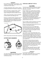
5 2K23A
OPERATORS
MANUAL
an Authorized Encore Dealer. To ensure
optimum performance and safety, always
purchase genuine Encore replacement parts
and accessories
GENERAL
This manual contains techincal data on the
following Encore commercial mowers.
SIGNAL WORDS
52K650ZP ; 52K700ZP ; 52K850ZP ; 61K650P
61B850P ; 61B950P ; 61K650ZP ; 61K700ZP
61K850ZP ; 61B850ZP ; 72B850P ; 72B950P
72B850ZP ; 72K850ZP -- 52K23A ; 52K25A 52K27L ;
61K27L; 51B27LD ; 61K25A ; 61B31LP 72K27L ;
72B27LD ; 72B31LP
INTRODUCTION
This symbol means “Attention! Become
Alert! Your Safety is Involved!” The symbol
is used with the following signal action words
to attract your attention to safety messages.
The message that follows the symbol contains important information about safety.
Your mower was built to the highest standards in
the industry. However, the prolonged life and
maximum efficiency of your mower depends on
you following the operating, maintenance and
adjustment instructions in this manual.
We encourage you to contact your local Encore
dealer for repairs. All Encore dealers are
informed of the latest methods to service this
equipment and provide prompt and efficient
service. They carry a full line of Encore service
parts.
Signal Word:
WARNING:
The signal action word “ WARNING” denotes
that a hazard exists on or near the machine
that can result in injury or death if proper
precautions are not taken.
A replacement Operator’s Manual is available
from your Encore Dealer or by contacting
Encore Manufacturing Co., Inc., Service
Department at PO Box 888, Beatrice, NE
68310. Please indicate the complete model
and serial number of your Encore product.
CAUTION:
The “Right” and “Left”,”Front” and “Rear” of the
machine are referenced from the operator’s
perspective when in the normal operating
position and facing forward travel direction.
The signal action word “CAUTION” is a reminder of safety practices on or near the
machine that could result in personal injury if
proper precautions are not taken.
GENERAL SAFETY INSTRUCTIONS
NOTES:
READ THIS OPERATOR’S MANUAL and
instructions furnished with attachments.
Perform only those maintenance procedures
described in this manual. If major repairs are
ever needed or assistance is desired, contact
The signal action word “NOTES” denotes
relevant information to assist you in the performance of a task.
1
ENCORE PROWLER MID CUT
Your mower is only as safe as the operator!
Operator carelessness or error may result in
serious bodily injury. Improper maintenance of the
machine may also result in injury. Please read and
follow these instructions on Safe Operation and be
certain that anyone using this mower fully
understands and follows these instructions.
1.
Familiarize yourself with the controls and know
how to stop the rider and mower deck quickly.
Drive levers must be in the Neutral position and
the Blade Clutch must be disengaged before
starting engine.
9.
Operator must wear proper shoes and clothing,
which may include safety glasses and ear protection.
10. Mow only during daylight hours or under very good
artificial light.
WARNING:
11. The safety shield over the Grass Discharge area
must always be bolted in place and in the DOWN
position unless the Grass Catcher is being used.
DO NOT allow children to operate the machine.
DO NOT allow any adult to operate the
machine without proper instruction.
2.
8.
12. If a solid object has been hit by the blades stop the
machine and check for damage. Repair or replace
any damaged/broken part prior to restarting the
engine.
Inspect your work area carefully. Remove debris
from the area to be cut. Keep all bystanders away
from the mowing area.
13. To avoid burns, DO NOT TOUCH the engine or
muffler immediately after operation.
3.
Avoid contact with moving parts. Keep hands and
feet clear of the mower deck.
14. Disengage blades when transporting and when
crossing walks and gravel roads.
4.
Never direct the discharge of material toward
bystanders nor allow anyone near the machine
while in operation.
5.
The machine is not intended for highway or street
use. Never carry passengers!
15. Do NOT mow close to drop-offs, deep ditches or
other hazards. Do NOT stop or start suddenly
when going uphill or downhill. Mow up and down
the face of steep slopes; NEVER mow across the
face. If a steep hill must be ascended, BACK up
the hill, drive forward when descending.
6.
Never tamper with safety devices or guards. If a
guard or safety device is damaged or removed,
replace it before operating the rider.
7.
Handle gasoline carefully. Use an approved
gasoline container. Fill the fuel tank, to within 1"
from the neck, with good quality unleaded gasoline.
16. Reduce speed and exercise extreme caution on
slopes and in sharp turns to prevent tipping or loss
of control. Be especially cautious when changing
direction on slopes.
17. The Mid-Cut Prowler is NOT designed for towing.
Only factory approved Grass Collection
Systems are permitted.
CAUTION:
Never add fuel to the tank while the engine is
running or hot. ALWAYS WAIT at least five
minutes before refueling and REFUEL WITH THE
ENGINE OFF. KEEP FUEL AWAY FROM
SPARKS OR FLAMES. WIPE AWAY any fuel
spillage BEFORE starting unit. Never fill the fuel
tank indoors. Wipe up any spilled gasoline.
Gasoline is highly flammable - NO SMOKING.
2
5. Place breather cap on oil tank. Note: The oil tank
is pre-filled from the factory with 20w50 oil and
should be visible in the sight glass located on the
back of the tank. The correct level is mid-point in
the sight glass.
ASSEMBLY INSTRUCTIONS:
1. Remove tractor from the crate. Lay out all the
hardware and parts from the inner box:
Parts will consist of:
1 - seat
1 - bolt bag
1 – literature packet
2 - handles
Battery:
2. Open bolt bag and lay out
Important for units prior to SN 43276:
1 - oil breather cap
4 - 5/16-18 X 1 ¼ bolt
4 - 5/16-18 whiz lock nut
4 - 5/16-18 nylock nut
4 - 5/16- std flat washers
Do not overfill battery! Electrolyte will
overflow onto parts of the machine,
resulting in severe corrosion.
THE MACHINE IS SHIPPED WITH A DRY
BATTERY!!
Units SN 43276 & above have sealed
battery - Require no filling or charging
3. Take 4 - 5/16 std flat washers and 4 - 5/16
nylock nuts and bolt the seat into place. Slide the
studs of the seat though the seat plate and secure
with one flat washer and nylock nut on each of the
4 studs. (Slide the seat all the way back onto seat
tracks in order to flip seat forward.) At this time
you may also connect the seat switch wires.
1. Remove the battery from the machine. Tilt seat
up to gain access to the battery. Disconnect
battery cables- NEGATIVE (black) CABLE FIRST.
Remove battery hold down and lift battery out.
2. Place battery on a level surface and remove
vent caps.
4. Using the 4 - 5/16 – 18 X 1 ¼ bolts, bolt the
handles into place. Note: Handle mounts to the
outside of the square control block with whiz locks
located on slotted or handle side.
3. Fill cells with battery grade sulfuric acid (1.265
specific gravity) to halfway between the top of the
separators and bottom of vent well.
4. Let battery stand for ½ hour after filling.
If battery acid level has fallen, refill to level above
plates.
5. Charge the battery at 4 to 5 amps for 3-5 hours.
6. After charging, install vent caps and wash off
any acid with water and dry battery.
7. Install battery in machine and secure battery
hold-down. DO NOT over tighten.
When reconnecting the battery cables the
POSITIVE (red) CABLE MUST BE ATTACHED
FIRST, then connect the Negative (black) Cable
and black wire to the battery terminal. Slip the
insulator boot over the Positive Terminal.
NOTE: If time does not permit charging the
battery, or if charging equipment is not available,
follow steps 1-4 and install as described in step 7.
Then run to vehicle continuously for 20 to 30
minutes to sufficiently charge the battery.
3
Fuel and Oil Recommendations
If gasoline is spilled, wipe it up immediately.
NOTE:
DIESEL UNITS FUEL:
Consult Engine Manual for Engine
Manufactures Recommendations on
Operation and Maintenance Information.
CAUTION:
On Diesel engine model series 432447, 522447
& 582447 - THESE ENGINES ARE CERTIFIED
TO OPERATE ON DIESEL FUEL ONLY.
CAUTION:
Engines are NOT shipped serviced from
factory. You must service engine before
cranking it!
Use clean, fresh diesel with a minimum of 40
cetane. Purchase fuel in quantity that can be used
within 30 days to assure fuel freshness.
GAS UNITS FUEL:
Use only clean, fresh, unleaded regular grade
gasoline.
Note: DO NOT use kerosene or gasoline instead
of diesel fuel. Failure to observe this caution will
damage engine.
CAUTION:
Do not mix oil with gasoline.
ALL UNITS FUEL LEVELS:
OCTANE RATING:
Keep tank full. Do NOT over fill. Allow space in
tank for fuel expansion. Check for fuel leaks at fuel
filter, injector pump, fuel pipes and etc.
The octane rating of gasoline is a measure of its
resistance to “knocking”. Using a minimum of 87
octane by the anti-knock index is recommenced.
The anti-knock index is posted on service station
pumps in the U.S.A.
If the fuel tank does run dry and the engine is
equipped with a fuel filter with priming pump,
stroke the pump to bleed the air from the fuel filter
system.
NOTE: If “knocking or pinging” occurs, use a
different brand of gasoline or higher octane rating.
ENGINE OIL:
CAUTION:
Oxygenates (either ethanol or MTBE) are added
to the gasoline. If you use the oxygenated fuel be
sure it is unleaded and meets the minimum octane
rating requirement.
ENGINES ARE SHIPPED WITHOUT OIL.
SERVICE ENGINE AND RECHECK OIL LEVEL
BEFORE STARTING.
! WARNING !
Gasoline is extremely flammable and can be
explosive under certain conditions.
Before refueling, turn the engine switch OFF. Do
not smoke! Make sure the area is well ventilated
and free from any source of flame or sparks,
including any appliances with a pilot light. Never
fill tank so that fuel level rises into the filler neck. If
tank is overfilled, heat may cause fuel to expand
and overflow through vents in tank cap. After
refueling make sure tank cap is securely closed.
The following oils are recommended for gasoline
engines.
API Service Classification: SF, SG, SH or SJ
4
4. Set Engine Choke Control to for cold starts to
FULL position.
NOTE:
Using multi-grade oils (5w-20, 10w30, and 10w40)
will increase oil consumption. Check oils more
frequently when using them.
FOR DIESEL UNITS: WITH THE THROTTLE SET
IN “SLOW “POSITION, TURN THE KEY TO THE
“ON” POSITION AND WAIT APPROXIMATELY 5
SECONDS FOR THE GLOW PLUGS TO CYCLE
(INDICATOR LIGHT SHOULD BE ON WHILE
PLUGS ARE PREHEATING COMBUSTION
CHAMBER). WHEN THE LIGHT GOES OUT,
TURN THE KEY TO THE “START” POSITION.
Let the engine warm up for a few minutes before
applying load.
ENGINE OIL CAPACITIES:
NOTE:
Consult Engine Manual for Engine
Manufactures Recommendations on
Operation and Maintenance Information.
5. Set Throttle to approximately half throttle and
turn key to “START” position. Release to run as
soon as engine starts. NOTE: Prolonged cranking
Gasoline two cylinder Models FD671D, FD711D
and FD750D hold 1.8L or 1.9 Qrts. when oil filter is will damage the starter motor and shorten battery
NOT removed. When filter is removed 2.0L or 2.1 life.
Qrts.
6. Adjust Engine Throttle and Choke for desired
Engine models FH601D, FH641D and FH680 hold engine smoothness and speed. NOTE: Let engine
warm up for 3 to 4 minutes before applying load.
1.4L or 1.5 Qrts. when filter is NOT removed.
When filter is removed 1.6L or 1.7 Qrts.
STOPPING ENGINE:
DIESEL OIL CAPACITY INCLUDING OIL FILTER
1. Lower the engine speed to an idle. Keep
IS APPROXIMATELY 3.3L OR 3.5 QRTS.
engine running at idle for about one minute.
COOLANT:
2. Turn the engine switch to “OFF” position.
Engines that are liquid cooled use a 50/50%
EMERGENCY STOP:
mixture of phosphate –free antifreeze and tap
water. This 50/50 % mixture is required for heat
dissipation, operation at low ambient temperature, Immediately turn the engine key to the OFF
position and close the fuel valve.
rust resistance and lubrication. Fill radiator
reservoir to bottom of the fill cap seat.
! WARNING !
Check coolant daily before starting the engine. Be ALWAYS REMOVE THE KEY FROM THE
SWITCH WHEN LEAVING EQUIPMENT
sure the engine is level. Check coolant level only
at the overflow reservoir located at the side of the UNATTENDED OR WHEN EQUIPMENT IS NOT
IN USE.
radiator. The cooling system is a closed type.
Never open the radiator cap, doing so may induce
TEST OPERATION:
air into the cooling system and may cause over
heating. The coolant level should be between the
Once the engine is started you are ready to test
“H” and “L” marks on over flow bottle.
drive the unit. NOTE: IF THE OPERATOR IS
INEXPERIENCED WITH THE ZERO TURNING
STARTING ENGINE:
RADIUS LEVER STEERING & SPEED
CONTROL, HE/ SHE SHOULD FOLLOW THESE
1. Move levers to the center of the control
RECOMMENDATIONS.
panel and place them in the lock out position by
pushing them outward.
2. Set the Parking Brake to the ON position.
3. Make sure that the PTO is disengaged, by
pushing the switch to the DOWN position.
5
TEST OPERATION – (continued)
1. Release the Park Brake Lever by pushing it
forward.
2. To drive unit bring both handles in so that they
are positioned in front of the operator. Slowly
move the handles forward to increase speed,
ease handles forward evenly. To decrease
speed ease handles back. To back up
continue to ease handles all the way back
toward the operator. To “zero turn” slowly
move the right handle forward to turn left or left
handle forward to turn right. To prevent turf
tear when zero turning always ease unit into
reverse and ease either right or left lever
forward.
3. Engage mower blades by pulling up on PTO
switch. Note: Discharge chute should always
be in the DOWN position. Never point
discharge toward bystanders.
4. To STOP, disengage PTO Switch and slow
engine to half throttle. Move Control Levers to
Lock or Neutral position and apply Park Brake.
Let unit run at ½ throttle for 60 seconds, for a
cool down period before turning key to OFF
position.
WARNING MAY RESULT IN INJURY TO
YOURSELF AND OTHERS OR PROPERTY
DAMAGE COULD RESULT.
CONTROL LOCATIONS:
4.
5.
7.
8.
REVERSE
NEUTRAL
FORWARD
1.
2.
3.
CONTROLS:
6. GAS UNITS
Your Encore Prowler is equipped with a Safety
Interlock System that is designed to help prevent
possible serious injuries. Understanding and
maintaining this system is vital for safe operation.
FUEL
TANKS
OFF
TO START ENGINE:
1.
2.
3.
4.
LEFT
FUEL
TANK
RIGHT
FUEL
TANK
Blades (PTO) switch must be OFF.
Control Levers must be in Neutral position.
Park Brake must be ON.
Operator must be in seat.
6. DIESEL UNITS
LEFT
FUEL
TANK
FUEL
TANKS
OFF
RIGHT
FUEL
TANK
1.
2.
3.
4.
5.
6.
7.
Ignition Key- On front control panel
Engine Throttle- On front control panel
Engine Choke – On front control panel
Blade Switch – Right hand console
Parking Brake – Left hand console
Fuel Valve- On front panel
Indicator Lights (oil, alt and temp) - Right
hand console.
8. Diesel units will have glow plugs and fuel filter
lights located on the left console.
9. Hour meter is located behind the seat on the
left hand side standing in front of the machine.
10. Serial Plate is located under the seat, on the
inside of the right side of the seat frame.
ENGINE WILL KILL IF:
1. The operator leaves the seat with ANY
or ALL the following conditions.
* The Control Levers OUT of Neutral.
* The Blade (PTO) switch is engaged.
* Park Brake in the OFF position.
2. The Park Brake is set BEFORE the Control
Levers are in Neutral.
! WARNING !
DO NOT OPERATE MOWER WITH THE
INTERLOCK SYSTEM DISCONNECTED OR
MALFUNCTIONING. FAILURE TO HEED THIS
6
4. All neutral creep (rotation) should be adjusted
out of the drive. This adjustment is performed
at the adjustable Pump Link on each
corresponding pump. ( See fig. ) Loosen the
jam nut between the ball stud and the control
rod. Tread the stud into the control rod if there
is forward rotation and out of the control rod if
there is reverse rotation. Never adjust the link
more than 2 full turns at a time. Retighten the
jam nut and start the engine, and repeat step
#2.
5. If the wheel still rotates in the Neutral Lock
position with the brake OFF repeat step #4.
DRIVE ADJUSTMENTS:
If the mower is not tracking straight or if the unit
creeps in the “Neutral Stop” position proceed with
the following instructions.
TIRE PRESSURE:
Checking air pressure in the tires is critical for
proper drive or tracking.
NOTE: DO NOT ADD ANY TYPE OF TIRE LINER
OR FOAM FILL MATERIAL TO THE TIRES!
Excessive loads created by foam filled tires may
cause failures to the hydro drive system, frame
and other components. Foam filling tires will void
warranty.
TRACKING ADJUSTMENT:
If the machine pulls left or right on a level, flat
surface begin by checking the tire pressure. The
front tires should have 20 to 22 PSI and the rear
tires should have 12 to 14 PSI. If tire pressures
are correct examine the dampening cylinders. The
cylinders are preset from factory to limit the
forward motion of the control levers. (When the
control lever is at full speed, all the way forward in
the control slot, the damping cylinder should
bottom out.) To adjust tracking, loosen the two
bolts on the cylinder adjusting plate. Push
adjusting plate to move the cylinder forward on the
fast side. This will restrict the movement of the
control lever to even out tracking. Always slow the
fast side of the machine down if tracking is
necessary.
Note: On uneven surfaces the operator is
responsible in keeping the machine traveling
in a straight line.
Front tires: 20 to 22 psi
Drive tires: 12 to14 psi
NEUTRAL ADJUSTMENTS – DRIVE:
1. Raise the drive wheels of the mower off of the
ground. Safely block the frame in this position
so it is secure.
2. With the unit blocked up securely and the
arms in the neutral position (in the lock out
position) sit in the operators seat and start the
engine. With the engine running release the
park brake and check to see if there is any
wheel creep (any rotation).
3. If wheels rotate with the control levers in lock
position, stop the engine and remove the belt
cover between the seat frame and engine by
removing the 2 - ¼ x ¾ bolts.
CYLINDER ADJUSTING PLATE
SPEED
CYLINDER
PUMP LINK
( SLOWER )
JAM NUT
( FASTER )
7
REVERSE LIMIT
STOP
RETURN
LINK
5. Reassemble the spring rod and replace the
clevis pin. Now move the deck up and down
and recheck the side to side blade
measurement.
LEVELING THE DECK:
The deck comes from the manufacturer preleveled. If the deck does not appear to be cutting
level, follow this procedure.
BELT ADJUSMENT:
1. Set all tire pressures to correct specification.
2. Place machine on a level cutting surface and
inspect blades to make sure that one is not
damaged or bent.
3. Stop engine and Remove the ignition key.
While wearing heavy gloves rotate the blades
so that they are all pointing to the forward side
of the deck. (See fig.1) Measure from the
blade tip to the ground on all three blades. If
there is more than 3/16" difference from one
side of the deck to the other, the deck should
be leveled.
Remove the key from ignition switch. Flip up the
floor plate (See fig. 3) to gain access to the deck
drive belt and the eyebolt assembly that is used
for adjusting the spring tension. The spring tension
is measured by the gap between the coils and
should be approximately 1/8". By turning the 5/
16" nylock nut on the end of the eyebolt clockwise,
it will increase tension. Moving the deck bracket
into the second slot (See fig. 3) may also increase
tension.
BLADE TIPS
DISCHARGE
SIDE
( BOTTOM VIEW )
FIG. 1
FIG. 3
4. To adjust the deck height, remove the clevis
pin from the lift spring rod. This may be
accomplished by moving the lift arm to a point
that relieves the pressure off the pin. (See fig.
2) To raise the deck, thread the back of the
BELT TENSION ADJUSTMENT
MAINTENANCE
! CAUTION !
Before performing any maintenance work, turn OFF
engine, remove key and disconnect Spark Plugs. Use
extreme care when working on machinery. Do not wear
loose fitting clothes, and observe all common safety
practices with tools. Also let all hydraulic and engine
parts cool before servicing any filters or engine parts.
CLEVIS PIN
LIFT SPRING
ROD
! BATTERY WARNING !
AVOID SERIOUS INJURY OR DEATH:
LIFT SPRING
SPRING TENSION
BOLT
THE BATTERY CONTAINS SULFURIC ACID.
AVOID CONTACT WITH SKIN, EYES OR
CLOTHING.
FIG. 2
spring rod clockwise. To lower the deck, turn
the spring rod counter clockwise (Note: That
when changing the length of the spring rod do
so in two turn increments). At this time also
inspect the bushings or washers, at the base
of the spring (by the spring bolt) and check for
binding.
8
ANTIDOTE: INTERNAL- DRINK LARGE
QUANTITIES OF WATER OR MILK, FOLLOW
WITH MILK OF MAGNESIA, BEATEN EGGS OR
VEGETABLE OIL. CALL PHYSICIAN
IMMEDIATELY. EYES AND SKIN SHOULD BE
FLUSHED WITH WATER AND GET PROMPT
MEDICAL ATTENTION.
BATTERIES PRODUCE EXPLOSIVE GASES.
KEEP SPARKS, FLAMES AND SMOKING
MATERIALS AWAY. VENTILATE WHEN
CHARGING IN AN ENCLOSED SPACE. WEAR
EYE PROTECTION WHEN WORKING NEAR
BATTERIES.
Lug nuts should be checked regularly for
tightness. Torque lug nuts to 50ft./lbs. The center
hub nut should be torqued to 175-200ft./lbs.
LOCATED BY THE WHEEL
MOTOR AREA
SWIVEL
ADJUST CLAMP COLLAR TO
APPROX. 3/16" GAP FROM
SWIVEL WITH BRAKE ON
CLAMP COLLAR
SWIVEL
BRAKE
ASSEMBLY
BRAKE
LINK
HAIR PIN
CLIP
LOCATED BY THE SEAT AREA
UNDER METAL FENDER
KEEP OUT OF REACH OF CHILDREN.
Keep the electrolyte level above the plates in each
cell by adding distilled water, as it becomes
necessary. Add water just before operating the
mower to mix the water with solution. Be careful
not to over fill the battery, the electrolyte solution is
corrosive and can cause damage to surrounding
metal parts if it should spill. Keep your battery at
1.260 specific gravity charge. When taking the
battery out of the mower for servicing, make sure
to reconnect the cables to the Battery, exactly as
they were prior to removal. Keep the battery clean.
Remove corrosion around the battery terminals by
applying a solution of one part baking soda to
four parts water. Coat all exposed terminal
surfaces with a light layer of grease or petroleum
jelly to prevent corrosion.
BRAKES:
After the first 40 hours of use check brakes for
adjustment. Brakes are adjusted by setting the
lock collars on the brake rods located by each
drive wheel. There must be 1/8 to 1/4 inch of gap
between the lock collar and swivel with the brake
in the ON position. This distance should be
checked bi-weekly. After adjusting the lock collar,
you may have to also adjust the brake link by
pulling the hair pin clip and adjusting swivel
accordingly.
MOWER BLADES:
New Blade
DRIVE BELTS:
25 Degrees
All drive belts are spring loaded and selftensioning, however, after the first 8-10 hours of
operation, the belts should be checked for proper
alignment and wear. There after check the belts
every 40 hours of operation or weekly, whichever
occurs first.
When Notch Starts
Discard Blade
Dangerous!
Service interval: Daily
Stop engine, set park brake, and remove engine
key before servicing blades.
Raise the mower deck to the highest position.
! WARNING !
Always wear proper hand and eye protection
when working with cutter blades.
Check the cutter blades for straightness. If the
cutter blades appear bent, they will need to be
replaced.
TIRES:
Correct tire pressure is essential for efficient
operation of the mower. Check tire air pressure
periodically. Inflate tires to the pressure listed:
Front Tires 20 to 22 psi
Dive tires 12 to 14 psi
9
! WARNING !
Do not attempt to straighten a bent blade or weld
a broken or cracked blade. Always replace it with
a new blade to assure safety.
CHECKING LUBRICANT LEVELS:
CAUTION
If a blade cutting edge is dull or nicked, it should
be sharpened. Remove the blades for sharpening.
Raise cutter deck to transport position. Lift the
front of unit using jack stands or equivalent
support making sure that the machine is secure.
Clean out any grass build-up from the underside
of the deck and in deck discharge chute.
Remove or install the blades by placing a block of
wood between the front or rear baffles and the
blade. When replacing the blade bolt be sure the
spring disk washer cone is installed toward the
bolt head (See fig. 1).
BLOCK OF WOOD
The fluid level in the gear box should be checked
after every 100 hours of operation or bi-weekly,
which ever occurs first.
Remove ignition key and raise deck to transport
position. Clean and remove the check plug from
the side of the gearbox. Visually check that the
lubricant level is up to the bottom edge of the
check-plug hole. If lubricant is low, add SAE
80W90 lubricant through the check-plug hole.
Install the check plug and tighten securely.
The lubricant in the cutter deck gearbox should be
changed after every 500 hours of operation or
yearly, whichever occurs first.
Place a suitable container beneath the cutter deck
gearbox and locate the gearbox drain plug.
Remove the drain plug, drain the lubricant into the
container and properly discard it.
Reinstall the drain plug and add SAE 80w90
lubricant through the check-plug in the gearbox,
until it is level with the bottom of the check-plug
hole. Install the check plug and tighten securely.
HYDRAULIC SYSTEM:
The hydraulic oil should be changed after every
500 hours or annually, which ever comes first. The
oil should also be changed if the color of the fluid
NOTE: Always balance the blade after sharpening. has become black or milky. A black color and/or a
rancid odor usually indicates possible over heating
of the oil, and a milky color usually indicates water
CUTTER DECK GEARBOX:
in the hydraulic oil.
FIG. 1
52-61" MID CUT
GEAR BOX
72" MID CUT
GEAR BOX
CAUTION
The cutter deck gearbox can reach high operating
temperatures. Allow the cutter deck gearbox to
cool before servicing.
Park mower on a level surface and stop the
engine. Place a suitable container under the
hydraulic oil reservoir. Remove the fill cap from the
reservoir. Remove the drain plug from the bottom
of the tank and allow oil to drain into the container.
While the reservoir is draining replace the
hydraulic filter.
Replace the drain plug and fill reservoir to sight
glass (located in the rear side of the tank) with
20W50 motor oil. This will require approximately
7qts of oil.
! WARNING !
To avoid serious Burn injuries:
Allow engine, and hydraulic fluids to cool before
servicing transmission or engine systems.
10
Maintanence Reference Information
LOCATED UNDER THE ENGINE
TO THE REAR OF THE MACHINE
F.
G.
A.
A.
72" MID CUT
GEAR BOX
52-61" MID CUT
GEAR BOX
LOCATED TO REAR
OF THE DECK
B.
C.
B.
E.
D.
C.
Grease Fitting Lubrication List
A.
B.
C.
D.
Control Arm Pivots
1 Pump / 100 Hours
Caster Support Bearing
5 Pumps / 250 Hours
Front Caster
2 Pumps / 40 Hours
Pivot Joints ( Left & Right Side)
1 Pump / 40 Hours
E.
Back Rail
1 Pump / 40 Hours
Drive Shaft
1 Pump / 40 Hours
Power Shaft Bearings
1 Pump / 250 Hours
F.
G.
INTERVAL
MAINTENANCE
DAILY
CHECK AND ADD ENGINE OIL
CHECK FOR LOOSE OR LOST NUTS AND SCREWS.
CHECK FOR FUEL AND OIL LEAKAGE.
CLEAN AIR CLEANER PAPER ELEMENT.
EVERY
25 HR.
EVERY
50 HR.
EVERY
100 HR.
EVERY
200 HR.
EVERY
300 HR.
CLEAN DUST AND DIRT FROM CYLINDER AND
CYLINDER HEAD FINS. TIGHTEN NUTS AND SCREWS.
CHANGE ENGINE OIL.
CLEAN AND REGAP SPARK PLUG.
CHANGE OIL FILTER.
REPLACE AIR CLEANER PAPER ELEMENT.
CLEAN COMBUSTION CHAMBER. CHECK AND ADJUST VALVE CLEARANCE. CLEAN AND LAP VALVE SEATING SURFACE. : SERVICE MORE FREQUENTLY UNDER DUSTLY CONDITIONS.
: HAVE AN AUTHORIZED ENGINE MFG DEALER PERFORM THESE SERVICES
.
11
NOTE:
Consult Engine Manual for
Engine
Manufactures
Recommendations
on
Operation and Maintenance
Information.
CHEAK OR CLEAN AIR INTAKE SCREEN.
CLEAN AIR CLEANER FOAM ELEMENT.
FIRST
8 HR.
Notes:
Notes:
ENCORE WARRANTY
For Prowler and Z Series Mowers
(excluding the Z 34)
This warranty extends to the original retail purchaser only and commences on the date of original
retail purchase. Any part of the Encore commercial mower manufactured by Encore Mfg. Co.,
Inc. and found in reasonable judgment of Encore Mfg. Co., Inc. to be defective in material or
workmanship will be repaired or replaced by an Authorized Encore Dealer without charge for
parts and labor. The Encore mower including any defective part must be returned to an Authorized Encore Service Dealer within the warranty period. The expense of delivering the mower to
the dealer for warranty work and the expense of returning it back to the owner after repair or
replacement will be paid by the owner. This warranty is limited to two years for frame, deck,
hydrostatic drive system (excluding hoses), cutter housings, gearbox, and driveshaft. The warranty will be 2 years from the date of purchase against defects in workmanship and materials
(90 days for rental use) for any Encore rider that is used for homeowner, commercial or any other
income producing purpose. Belts, batteries, and tires are warranted for 90 days against defects
in materials and workmanship.
Cutter housings, electrical components, hydraulic components and electric-clutch must be returned before warranty will be paid.
The engine is covered by its respective manufacturer please refer to the manufacture’s warranty
statement that is included in the literature packet. Engine warranties should be referred to the
nearest authorized service outlet of the engine manufacturer.
The responsibility of Encore Mfg. Co., Inc. in respect to claim is limited to making the required
repairs or replacements, and no claim of breach of warranty shall be cause for cancellation or
recession of the contract of sale of any Encore mower.
Proof of purchase is required by both Encore and the servicing Dealer, before any warranty will
be paid, and warranty work must be preformed by an Authorized Encore service dealer.
This warranty does not cover any Encore mower that has been altered or modified so as to
adversely affect the intended use of the product, it operation, performance, or durability. This
warranty also does not cover any mower that has been subject to misuse, neglect, negligence,
accident or that has been operated in any way contrary to the operating instructions as specified
in the Operators Manual.
Encore Mfg. Co., Inc. reserves the right to change or improve the design of any mower without
assuming any obligation to modify any mower previously manufactured.
Encore Mfg. Co., Inc. obligation under warranty is strictly and excessively limited to repair or
replacement of defective parts. Encore Mfg. Co., Inc. does not assume or authorize anyone to
assume for them any other obligation.
ENCORE MFG. CO., INC. CANNOT BE RESPONSIBLE FOR THE WAY YOU OPERATE, OR
THE CONDITIONS IN WHICH YOU OPERATE THE MOWER. USE COMMON SENSE AT ALL
TIMES.
As of May 1, 2003 this warranty statement supersedes any warranty statement published by
ENCORE MANUFACTURING CO., INC.
0802 B ,ENCORE MANUFACTURING CO., INC.
All rights reserved. Contents subject to change.
PROWLER MID-CUT
52K23A - OPERATORS MANUAL
Part Number
933095