1
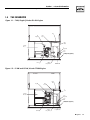
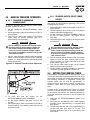
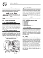
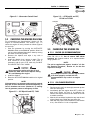
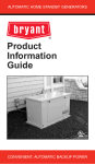
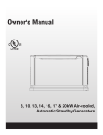
Owner’s Manual Air-cooled, Prepackaged Automatic Standby Generators Models: ASPAS1BBA007 (6 kW NG, 7 kW LP) ASPAS1BBA012 (12 kW NG, 12 kW LP) ASPAS1BBA015 (13 kW NG, 15 kW LP) US C LISTED GENERAC R POWER SYSTEMS, INC. R ! Not intended for use as Primary Power in place of utility or in life-support applications. DANGER DEADLY EXHAUST FUMES. OUTDOOR INSTALLATION ONLY!! ! INTRODUCTION Thank you for purchasing this model of the Bryant product line. This model is a compact, high performance, air-cooled, engine-driven generator designed to automatically supply electrical power to operate critical loads during a utility power failure. This unit is factory installed in an all-weather, metal enclosure that is intended exclusively for outdoor installation. This generator will operate using either vapor withdrawn liquid propane (LP) or natural gas (NG). READ THIS MANUAL THOROUGHLY If any portion of this manual is not understood, contact the nearest Bryant Dealer for starting, operating and servicing procedures. Throughout this publication, and on tags and decals affixed to the generator, DANGER, WARNING, CAUTION and NOTE blocks are used to alert personnel to special instructions about a particular operation that may be hazardous if performed incorrectly or carelessly. Observe them carefully. Their definitions are as follows: DANGER After this heading, read instructions that, if not strictly complied with, will result in serious personal injury, including death, in addition to property damage. After this heading, read instructions that, if not strictly complied with, may result in serious personal injury or property damage. After this heading, read instructions that, if not strictly complied with, could result in damage to equipment and/or property. NOTE: After this heading, read explanatory statements that require special emphasis. These safety warnings cannot eliminate the hazards that they indicate. Common sense and strict compliance with the special instructions while performing the service are essential to preventing accidents. Four commonly used safety symbols accompany the DANGER, WARNING and CAUTION blocks. The type of information each indicates follows: This symbol points out important safety ! information that, if not followed, could endanger personal safety and/or property of others. This symbol points out potential explosion hazard. This symbol points out potential fire hazard. This symbol points out potential electrical shock hazard. Bryant The operator is responsible for proper and safe use of the equipment. Bryant strongly recommends that the operator read this Owner's Manual and thoroughly understand all instructions before using this equipment. Bryant also strongly recommends instructing other users to properly start and operate the unit. This prepares them if they need to operate the equipment in an emergency. CONTENTS This manual contains pertinent owner’s information, including warranty, electrical diagrams, exploded views and lists of repair parts, for three different Bryant models: • ASPAS1BBA007 – 6 kW NG, 7 kW LP, single-cylinder GH-410 Engine • ASPAS1BBA012 – 12 kW NG, 12 kW LP, V-twin GT990 Engine • ASPAS1BBA015 – 13 kW NG, 15 kW LP, V-twin GT990 Engine OPERATION AND MAINTENANCE It is the operator's responsibility to perform all safety checks, to make sure that all maintenance for safe operation is performed promptly, and to have the equipment checked periodically by a Bryant Dealer. Normal maintenance service and replacement of parts are the responsibility of the owner/operator and, as such, are not considered defects in materials or workmanship within the terms of the warranty. Individual operating habits and usage contribute to the need for maintenance service. Proper maintenance and care of the generator ensures a minimum number of problems and keep operating expenses at a minimum. See a Bryant Dealer for service aids and accessories. HOW TO OBTAIN SERVICE When the generator requires servicing or repairs, contact a Bryant Dealer for assistance. Service technicians are factory-trained and are capable of handling all service needs. When contacting a Bryant Dealer about parts and service, always supply the complete model number and serial number of the unit as given on its data decal, which is located on the generator. See Figure 1.1 or Figure 1.2 in Section 1.4 for decal location. Model No. ____________ Serial No. ____________ Table of Contents Bryant Air-cooled 7 kW, 12 kW and 15 kW Generators Introduction ........................Inside Front Cover Section 3 – Maintenance ..............................12 Read This Manual Thoroughly ..............................IFC Contents ................................................................IFC Operation and Maintenance ..................................IFC How to Obtain Service ..........................................IFC 3.1 Fuses ................................................................12 3.2 Checking the Engine Oil Level ..........................13 3.3 Changing the Engine Oil....................................13 3.4 Changing the Oil Filter ......................................14 Safety Rules ........................................................2 3.5 Changing the Engine Air Cleaner......................14 Standards Index ........................................................3 3.6 Spark Plug(s) ....................................................14 3.7 Battery Maintenance..........................................15 Section 1 – General Information ..................4 3.8 Cooling System..................................................15 1.1 Unpacking/Inspection ..........................................4 3.9 Corrosion Protection ..........................................16 1.2 Protection Systems..............................................4 3.10 Attention After Submersion................................16 1.3 NEC Requirement for Arc Fault Circuit Interruption Breaker for Bedrooms ......................4 3.11 Out of Service Procedure ..................................16 1.4 The Generator ....................................................5 Section 4 – Service ..........................................17 1.5 Specifications ......................................................6 4.1 1.6 System Set LED ..................................................6 1.7 Fuel Requirements and Recommendations ........6 Section 5 – Troubleshooting ........................18 1.8 Fuel Consumption................................................7 5.1 1.9 Location ..............................................................7 1.10 Battery Installation ..............................................8 Service Schedule ..............................................17 Troubleshooting Guide ......................................18 Section 6 – Warranty ......................................19 1.11 The Battery ..........................................................8 Section 2 – Operation ......................................9 2.1 Break-in Procedure..............................................9 2.2 Using the Auto/Off/Manual Switch ......................9 2.3 Automatic Transfer Operation ..........................10 2.4 Sequence of Automatic Operation ....................10 2.5 Manual Transfer Operation................................11 2.6 Setting the Exercise Timer ................................11 2.7 Protection Systems............................................12 Bryant 1 IMPORTANT SAFETY INSTRUCTIONS Bryant Air-cooled 7 kW, 12 kW and 15 kW Generators SAVE THESE INSTRUCTIONS – The manufacturer suggests that these rules for safe operation be copied and posted near the unit’s installation site. Safety should be stressed to all operators and potential operators of this equipment. ! ! WARNING: ! GENERAL HAZARDS ! ! The engine exhaust from this product contains chemicals known to the state of California to cause cancer, birth defects or other reproductive harm. ! WARNING: ! This product contains or emits chemicals known to the state of California to cause cancer, birth defects or other reproductive harm. Study these SAFETY RULES carefully before installing, operating or servicing this equipment. Become familiar with this Owner’s Manual and with the unit. The generator can operate safely, efficiently and reliably only if it is properly installed, operated and maintained. Many accidents are caused by failing to follow simple and fundamental rules or precautions. Bryant cannot anticipate every possible circumstance that might involve a hazard. The warnings in this manual, and on tags and decals affixed to the unit are, therefore, not all-inclusive. If using a procedure, work method or operating technique Bryant does not specifically recommend, ensure that it is safe for others. Also make sure the procedure, work method or operating technique chosen does not render the generator unsafe. DANGER ! Despite the safe design of this generator, operating this equipment imprudently, neglecting its maintenance or being careless can cause possible injury or death. Permit only responsible and capable persons to operate or maintain this equipment. Potentially lethal voltages are generated by these machines. Ensure all steps are taken to render the machine safe before attempting to work on the generator. ! 2 Parts of the generator are rotating and/or hot during operation. Exercise care near running generators. Bryant ! • For safety reasons, Bryant recommends that the installation, initial start-up and maintenance of this equipment is carried out by a Bryant Dealer. • The engine exhaust fumes contain carbon monoxide, which can be DEADLY. This dangerous gas, if breathed in sufficient concentrations, can cause unconsciousness or even death. This exhaust system must be installed properly, in strict compliance with applicable codes and standards. Following installation, do nothing that might render the system unsafe or in noncompliance with such codes and standards. • Keep hands, feet, clothing, etc., away from drive belts, fans, and other moving or hot parts. Never remove any drive belt or fan guard while the unit is operating. • Adequate, unobstructed flow of cooling and ventilating air is critical to correct generator operation. Do not alter the installation or permit even partial blockage of ventilation provisions, as this can seriously affect safe operation of the generator. The generator MUST be installed outdoors. • When working on this equipment, remain alert at all times. Never work on the equipment when physically or mentally fatigued. • Inspect the generator regularly, and contact the nearest Bryant Dealer for parts needing repair or replacement. • Before performing any maintenance on the generator, disconnect its battery cables to prevent accidental start up. Disconnect the cable from the battery post indicated by a NEGATIVE, NEG or (–) first. Reconnect that cable last. • Never use the generator or any of its parts as a step. Stepping on the unit can stress and break parts, and may result in dangerous operating conditions from leaking exhaust gases, fuel leakage, oil leakage, etc. IMPORTANT SAFETY INSTRUCTIONS Bryant Air-cooled 7 kW, 12 kW and 15 kW Generators ELECTRICAL HAZARDS • All generators covered by this manual produce dangerous electrical voltages and can cause fatal electrical shock. Utility power delivers extremely high and dangerous voltages to the transfer switch as does the standby generator when it is in operation. Avoid contact with bare wires, terminals, connections, etc., while the unit is running. Ensure all appropriate covers, guards and barriers are in place before operating the generator. If work must be done around an operating unit, stand on an insulated, dry surface to reduce shock hazard. • Do not handle any kind of electrical device while standing in water, while barefoot, or while hands or feet are wet. DANGEROUS ELECTRICAL SHOCK MAY RESULT. • The National Electrical Code (NEC) requires the frame and external electrically conductive parts of the generator to be connected to an approved earth ground. Local electrical codes also may require proper grounding of the generator electrical system. • After installing this home standby electrical system, the generator may crank and start at any time without warning. When this occurs, load circuits are transferred to the STANDBY (generator) power source. To prevent possible injury if such a start and transfer occur, always set the generator’s Auto/Off/Manual switch to its OFF position before working on equipment and remove the 7.5A and 15A fuses from the generator control panel. • In case of accident caused by electric shock, immediately shut down the source of electrical power. If this is not possible, attempt to free the victim from the live conductor. AVOID DIRECT CONTACT WITH THE VICTIM. Use a nonconducting implement, such as a dry rope or board, to free the victim from the live conductor. If the victim is unconscious, apply first aid and get immediate medical help. • Never wear jewelry when working on this equipment. Jewelry can conduct electricity resulting in electric shock, or may get caught in moving components causing injury. FIRE HAZARDS • For fire safety, the generator must be installed and maintained properly. Installation always must comply with applicable codes, standards, laws and regulations. Adhere strictly to local, state and national electrical and building codes. Comply with regulations the Occupational Safety and Health Administration (OSHA) has established. Also, ensure that the generator is installed in accordance with the manufacturer’s instructions and recommendations. Following proper installation, do nothing that might alter a safe installation and render the unit in noncompliance with the aforementioned codes, standards, laws and regulations. • Keep a fire extinguisher near the generator at all times. Extinguishers rated “ABC” by the National Fire Protection Association are appropriate for use on the standby electric system. Keep the extinguisher properly charged and be familiar with its use. Consult the local fire department with any questions pertaining to fire extinguishers. EXPLOSION HAZARDS • Do not smoke around the generator. Wipe up any fuel or oil spills immediately. Ensure that no combustible materials are left in the generator compartment, or on or near the generator, as FIRE or EXPLOSION may result. Keep the area surrounding the generator clean and free from debris. • Gaseous fluids such as natural gas and liquid propane (LP) gas are extremely EXPLOSIVE. Install the fuel supply system according to applicable fuel-gas codes. Before placing the home standby electric system into service, fuel system lines must be properly purged and leak tested according to applicable code. After installation, inspect the fuel system periodically for leaks. No leakage is permitted. STANDARDS INDEX In the absence of pertinent standards, codes, regulations and laws, the published information listed below may be used as installation guide for this equipment. 1. NFPA No. 37, STATIONARY COMBUSTION ENGINES AND GAS TURBINES, available from the National Fire Protection Association, 470 Atlantic Avenue, Boston, MA 02210. 2. NFPA No. 76A, ESSENTIAL ELECTRICAL SYSTEMS FOR HEALTH CARE FACILITIES, available same as Item 1. 3. NFPA No. 54, NATIONAL FUEL GAS CODE, available same as Item 1. 4. NFPA No. 58, AMERICAN NATIONAL STANDARD FOR STORAGE AND HANDLING OF LIQUEFIED PETROLEUM GAS, available same as Item 1. 5. NFPA No. 70, NFPA HANDBOOK OF NATIONAL ELECTRIC CODE, available same as Item 1. 6. Article X, NATIONAL BUILDING CODE, available from the American Insurance Association, 85 John Street, New York, N.Y. 10038. 7. AGRICULTURAL WIRING HANDBOOK, available from the Food and Energy Council, 909 University Avenue, Columbia, MO 65201. 8. ASAE EP-3634, INSTALLATION AND MAINTENANCE OF FARM STANDBY ELECTRICAL SYSTEMS, available from the American Society of Agricultural Engineers, 2950 Niles Road, St. Joseph, MI 49085. 9. NFPA No. 30, FLAMMABLE AND COMBUSTIBLE LIQUIDS CODE, available same as Item 1. Bryant 3 Section 1 — General Information Bryant Air-cooled 7 kW, 12 kW and 15 kW Generators DANGER ! 1.1 Only qualified electricians or contractors should attempt such installations, which must comply strictly with applicable codes, standards and regulations. UNPACKING/INSPECTION After unpacking, for damage. carefully inspect the contents • This standby generator set has been factory supplied with a weather protective enclosure that is intended for outdoor installation only. • This UL listed standby generator set is packaged with an automatic transfer switch with built in load center. The combination transfer switch and load center is pre-wired with a two foot and 30 foot conduit. Circuit breakers for emergency circuit connections are included. • This UL listed, 2-pole switch is rated at 100 AC amperes at 250 volts maximum. This transfer switch is for indoor use only. If this generator is used to power electrical load circuits normally powered by a utility power source, it is required by code to install a transfer switch. The transfer switch must effectively isolate the electrical system from the utility distribution system when the generator is operating (NEC 700, 701 & 702). Failure to isolate an electrical system by such means will result in damage to the generator and also may result in injury or death to utility power workers due to backfeed of electrical energy. If any loss or damage is noted at time of delivery, have the person(s) making the delivery note all damage on the freight bill or affix their signature under the consignor's memo of loss or damage. If a loss or damage is noted after delivery, separate the damaged materials and contact the Bryant for claim procedures. “Concealed damage” is understood to mean damage to the contents of a package that is not in evidence at the time of delivery, but is discovered later. 1.2 PROTECTION SYSTEMS Unlike an automobile engine, the generator may have to run for long periods of time with no operator present to monitor engine conditions. For that reason, the engine is equipped with the following systems that protect it against potentially damaging conditions: 1. Low Oil Pressure Sensor 2. High Temperature Sensor 4 Bryant 3. Overcrank 4. Overspeed There are LED readouts on the control panel to notify personnel that one of these faults has occurred. There is also a “System Set” LED that is lit when all of the conditions describe in Section 1.3 are true. 1.3 NEC REQUIREMENT FOR ARC FAULT CIRCUIT INTERRUPTION BREAKER FOR BEDROOMS In 2001, the National Electric Code (NEC) introduced a requirement for new construction. This new requirement indicates the need for Arc Fault Circuit Interrupters to be used to protect the complete branch circuit that feeds a dwelling bedroom. The actual NEC requirement is indicated below. 1.3.1 SECTION 210.12 ARC FAULT CIRCUIT INTERRUPTER PROTECTION 1. Definition: An arc fault circuit interrupter is a device intended to provide protection from the effects of arc faults by recognizing characteristics unique to arcing and by functioning to de-energize the circuit when an arc fault is detected. 2. Dwelling Unit Bedrooms: All branch circuits that supply 125 volt, single-phase, 15 and 20 ampere outlets installed in dwelling unit bedrooms shall be protected by an arc fault circuit interrupter listed to provide protection of the entire branch circuit. Section 210.12 requires that AFCI protection be provided on branch circuits that supply outlets (receptacle, lighting, etc.) in dwelling bedrooms. The requirement is limited to 15 and 20 ampere, 125 volt circuits. There is no prohibition against providing AFCI protection on other circuits or in locations other than bedrooms. Because circuits are often shared between a bedroom and other areas such as closets and hallways, providing AFCI protection on the complete circuit would comply with 210.12. If during the installation of the Bryant Home Standby system the decision is made to provide back up power to a bedroom branch circuit, then the circuit breaker in the Bryant Transfer Switch should be replaced with an Arc Fault Circuit Interrupter. It is most important that breakers only be switched like for like. For instance, if replacing a 15A breaker, it MUST be replaced with a 15A AFCI breaker. Likewise, a 20A breaker MUST be replaced with a 20A AFCI. These AFCI breakers are available at the nearest electrical wholesaler or hardware store. Siemens Item # Description Q115AF 15A Single Pole AFCI Q120AF 20A Single Pole AFCI Section 1 — General Information Bryant Air-cooled 7 kW, 12 kW and 15 kW Generators 1.4 THE GENERATOR Figure 1.1 – 7 kW, Single Cylinder GH-410 Engine Oil Dipstick Control Panel Data Decal GFCI Outlet Exhaust Enclosure Fuel Regulator Fuel Inlet Lifting holes (4 places) Oil Filter Battery Compartment Figure 1.2 – 12 kW and 15 kW, V-twin GT-990 Engine Oil Dipstick Data Decal Control Panel GFCI Outlet Exhaust Enclosure Fuel Regulator Fuel Inlet Lifting holes (4 places) Oil Filter Battery Compartment Composite Base Bryant 5 Section 1 — General Information Bryant Air-cooled 7 kW, 12 kW and 15 kW Generators 1.5 SPECIFICATIONS 1.5.1 GENERATOR Model Rated Max. Continuous Power Capacity (Watts*) Rated Voltage Rated Max. Continuous Load Current (Amps) 120 Volts** 240 Volts Main Line Circuit Breaker Phase Number of Rotor Poles Rated AC Frequency Power Factor Recommended Air Filter Battery Requirement (At 0° F -17.8° C) Weight Output Sound Level @ 23 ft (7m) at full load Normal Operating Range ASPAS1BBA007 6,000 NG/7,000 LP 120/240 50.0 NG/58.3 LP 25.0 NG/29.2 LP 30 Amp 1 2 60 Hz 1 Bryant Part # 0C8127 Group 26 12 Volts and 350 Cold-cranking Amperes Minimum 375 Pounds 68 db (A) ASPAS1BBA012 12,000 NG/12,000 LP 120/240 ASPAS1BBA015 13,000 NG/15,000 LP 120/240 100.0 NG/100.0 LP 108.3 NG/125.0 LP 50.0 NG/50.0 LP 54.2 NG/62.5 LP 50 Amp 65 Amp 1 1 2 2 60 Hz 60 Hz 1 1 Bryant Part # 0C8127 Bryant Part # 0C8127 Group 26 Group 26 12 Volts and 12 Volts and 525 Cold-cranking 525 Cold-cranking Amperes Minimum Amperes Minimum 470 Pounds 487 Pounds 70.5 db (A) 71.5 db (A) -20°F (-28.8°C) to 104°F (40°C) * Maximum wattage and current are subject to and limited by such factors as fuel Btu content, ambient temperature, altitude, engine power and condition, etc. Maximum power decreases about 3.5 percent for each 1,000 feet above sea level; and also will decrease about 1 percent for each 6° C (10° F) above 16° C (60° F) ambient temperature. ** Load current values shown for 120 volts are maximum TOTAL values for two separate circuits. The maximum current in each circuit must not exceed the value stated for 240 volts. 1.5.2 ENGINE Type of Engine Number of Cylinders Rated Horsepower Displacement Cylinder Block Valve Arrangement Ignition System Recommended Spark Plug Spark Plug Gap Compression Ratio Starter Oil Capacity Including Filter Recommended Oil Filter Recommended Air Filter Operating RPM 1.6 ASPAS1BBA007 GH-410 1 14.5 @ 3,600 rpm 410cc Aluminum w/Cast Iron Sleeve Overhead Valves Solid-state w/Magneto RC14YC 0.76 mm (0.030 inch) 8.6:1 12 Vdc Approx. 1.5 Qts Bryant Part # 70185D Bryant Part # 0C8127 3,600 SYSTEM SET LED The “System Set” LED is lit when all of the following conditions are true: 1. The AUTO/OFF/MANUAL switch is set to the AUTO position. 2. The utility voltage being supplied to the unit is being sensed by the PCB. If the utility sense voltage is not connected to the unit or if it is below 168 volts AC, then the system set light will flash rapidly. This indicates that if the AUTO/OFF/ MANUAL switch is placed in the Auto position, the generator will start. 3. The “Not In Auto” dip switch is set to the OFF position on the control board. 6 Bryant ASPAS1BBA012 GT-990 2 30 @ 3,600 rpm 992cc Aluminum w/Cast Iron Sleeve Overhead Valves Solid-state w/Magneto RC12YC 0.508 mm (0.020 inch) 9.5:1 12 Vdc Approx. 1.7 Qts Bryant Part # 70185D Bryant Part # 0C8127 3,600 ASPAS1BBA015 GT-990 2 30 @ 3,600 rpm 992cc Aluminum w/Cast Iron Sleeve Overhead Valves Solid-state w/Magneto RC12YC 0.508 mm (0.020 inch) 9.5:1 12Vdc Approx. 1.7 Qts Bryant Part # 70185D Bryant Part # 0C8127 3,600 4. No alarms are present, for example, low oil pressure, high temperature, etc. 1.7 FUEL REQUIREMENTS AND RECOMMENDATIONS With LP gas, use only the vapor withdrawal system. This type of system uses the vapors formed above the liquid fuel in the storage tank. The engine has been fitted with a fuel carburetion system that meets the specifications of the 1997 California Air Resources Board for tamper-proof dual fuel systems. The unit will run on natural gas or LP gas, but it has been factory set to run on natural gas. Section 1 — General Information Bryant Air-cooled 7 kW, 12 kW and 15 kW Generators Should the primary fuel need to be changed to LP gas, the fuel system needs to be reconfigured. See Section 1.9 for instructions on reconfiguration of the fuel system. Recommended fuels should have a Btu content of at least 1,000 Btus per cubic foot for natural gas; or at least 2,520 Btus per cubic foot for LP gas. Ask the fuel supplier for the Btu content of the fuel. Required fuel pressure for natural gas is 5 inches to 7 inches water colum (0.18 to 0.25 psi); and for liquid propane, 11 inches to 14 inches of water column (0.4 to 0.5 psi). NOTE: Any piping used to connect the generator to the fuel supply should be of adequate size to ensure the fuel pressure NEVER drops below 4 inches water colum for natural gas or 10 inches water column for liquid propane for all load ranges. 1.8 FUEL CONSUMPTION *Natural gas is in cubic feet per hour. **LP is in gallons per hour/cubic feet per hour. *** Values given are approximate. Model # Nat. Gas (*) 1/2 Load Full Load 6/7 kW 66 119 12 kW 152 215 13/15 kW 156 220 LP Vapor (**) 1/2 Load Full Load 0.82/30 1.47/54 1.53/56 2.08/76 1.58/58 2.40/88 DANGER Gaseous fuels such as natural gas and liquid propane (LP) gas are highly explosive. Even the slightest spark can ignite such fuels and cause an explosion. No leakage of fuel is permitted. Natural gas, which is lighter than air, tends to collect in high areas. LP gas is heavier than air and tends to settle in low areas. 1.9 LOCATION ◆ 1.9.1 LIFTING THE GENERATOR To lift the generator, insert pipe having sufficient strength and diameter through the lifting holes which are located near the unit’s base (see Figure 1.1 and 1.2, page 5). You may also lift the unit using a hook and hoist method provided you utilize a spreader bar to ensure that the lifting lines clear the roof panel. ! Excercise caution when lifting the unit manually as it may shift on lifting pipes during transportation, which may result in injury. ◆ 1.9.2 PLACEMENT Install the generator set, in its protective enclosure, outdoors, where adequate cooling and ventilating air is always available. Consider these factors: • Install the unit where air inlet and outlet openings will not become obstructed by leaves, grass, snow, etc. If prevailing winds will cause blowing or drifting, consider using a windbreak to protect the unit. • Install the generator on high ground where water levels will not rise and endanger it. • Allow sufficient room on all sides of the generator for maintenance and servicing. A good rule is to allow three feet of space on all sides. • Where strong prevailing winds blow from one direction, face the generator air inlet openings to the prevailing winds. • Install the generator as close as possible to the fuel supply, to reduce the length of piping. • Install the generator as close as possible to the transfer switch. HOWEVER, REMEMBER THAT LAWS OR CODES MAY REGULATE THE DISTANCE. The genset must be installed on a level surface. The base frame must be level within two (2) inches all around. ◆ 1.9.3 TRANSFER SWITCH 1.9.3.1 7 kW, 12 kW and 15 kW Units The transfer switch shipped with this generator is enclosed in a NEMA 1 enclosure. This type of enclosure is intended for indoor use only. Follow these rules: • Install the transfer switch indoors on a firm, sturdy supporting structure. • To prevent switch distortion, level the switch if necessary. This can be done by placing washers between the switch enclosure and mounting surface. • Never install the switch where water or any corrosive substance might drip onto the enclosure. • Protect the switch at all times against excessive moisture, dust, dirt, lint, construction grit and corrosive vapors. DANGER When lifting or hoisting equipment is used, be careful not to contact overhead power lines. ! The generator’s weight of more than 300 pounds requires proper tools, equipment and qualified personnel to be used in all phases of handling and unpacking. If the AUTO/OFF/MANUAL switch is not set to its OFF position, the generator can crank and start as soon as the battery cables are connected. If the utility power supply is not turned off, sparking can occur at the battery posts and cause an explosion. Bryant 7 Section 1 — General Information Bryant Air-cooled 7 kW, 12 kW and 15 kW Generators 1.10 BATTERY INSTALLATION Fill the battery with the proper electrolyte fluid if necessary and have the battery fully charged before installing it. Before installing and connecting the battery, complete the following steps: 1. Set the generator's AUTO/OFF/MANUAL switch to OFF. 2. Turn off utility power supply to the transfer switch. 3. Remove the 7.5A and 15A fuses from the generator control panel. Battery cables were factory connected at the generator (Figure 1.5). Connect cables to battery posts as follows: Figure 1.5 – Battery Cable Connections 4. Connect the red battery cable (from starter contactor) to the battery post indicated by a positive, POS or (+). 5. Connect the black battery cable (from frame ground) to the battery post indicated by a negative, NEG or (—). NOTE: Damage will result if battery connections are made in reverse. NOTE: The generator is equipped with a battery trickle charger that is active when the unit is set up for automatic operation. With the battery installed and utility power source voltage available to the transfer switch, the battery receives a trickle charge while the engine is not running, to prevent self-discharge. The trickle charger is designed to help extend the life of the battery by maintaining the battery when the unit is not running. The trickle charge feature cannot be used to recharge a discharged battery. 1.11 THE BATTERY DANGER Do not dispose of the battery in a fire. The battery is capable of exploding. 8 Bryant A battery presents a risk of electrical shock and high short circuit current. The following precautions are to be observed when working on batteries: • Remove the 7.5A and 15A fuses from the generator control panel. • Remove watches, rings or other metal objects; • Use tools with insulated handles; • Wear rubber gloves and boots; • Do not lay tools or metal parts on top of the battery; and • Disconnect charging source prior to connecting or disconnecting battery terminals. ! Do not open or mutilate the battery. Released electrolyte has been known to be harmful to the skin and eyes, and to be toxic. ! The electrolyte is a dilute sulfuric acid that is harmful to the skin and eyes. It is electrically conductive and corrosive. The following procedures are to be observed: • Wear full eye protection and protective clothing; • Where electrolyte contacts the skin, wash it off immediately with water; • Where electrolyte contacts the eyes, flush thoroughly and immediately with water and seek medical attention; and • Spilled electrolyte is to be washed down with an acid neutralizing agent. A common practice is to use a solution of 1 pound (500 grams) bicarbonate of soda to 1 gallon (4 liters) of water. The bicarbonate of soda solution is to be added until the evidence of reaction (foaming) has ceased. The resulting liquid is to be flushed with water and the area dried. Lead-acid batteries present a risk of fire because they generate hydrogen gas. The following procedures are to be followed: • DO NOT SMOKE when near the battery; • DO NOT cause flame or spark in battery area; and • Discharge static electricity from body before touching the battery by first touching a grounded metal surface. ! Be sure the AUTO/OFF/MANUAL switch is set to the OFF position before connecting the battery cables. If the switch is set to AUTO or MANUAL, the generator can crank and start as soon as the battery cables are connected. Be sure the utility power supply is turned off and the 7.5A and 15A fuses are removed from the generator control panel, or sparking may occur at the battery posts as the cables are attached and cause an explosion. Section 2 — Operation Bryant Air-cooled 7 kW, 12 kW and 15 kW Generators Servicing of the battery is to be performed or supervised by personnel knowledgeable of batteries and the required precautions. Keep unauthorized personnel away from batteries. When replacing the battery, use the following type of battery: Group 26 12-volt DC, negative ground battery with a rating of 350 cold-cranking amps minimum for 7 kW; 525 cold-cranking amps minimum for 12 and 15 kW at -17.8° C (0° F) minimum. When using a maintenancefree battery, it is not necessary to check the specific gravity or electrolyte level. Have these procedures performed at the intervals specified in the “Service Schedule.” A negative ground system is used. Battery connections are shown on the wiring diagrams. Make sure the battery is correctly connected and terminals are tight. Observe battery polarity when connecting the battery to the generator set. 2.1 BREAK-IN PROCEDURE Once the unit has been installed and all electrical checks have been made, it is strongly recommended that the following “Break-in Procedure” be completed to ensure correct generator operation in the future. 1. Set the generator’s AUTO/OFF/MANUAL switch to AUTO. 2. Turn OFF the utility power supply to the transfer switch using the means provided (such as a utility main line circuit breaker). 3. The unit will start, and the transfer switch will transfer to standby. 4. Using the transfer switch’s built-in emergency load center, turn on circuits to load the generator to approximately 25% rated load and run the unit for one hour. 5. Run the unit for one hour at 50% rated load. 6. Run the unit for one hour at 75% rated load. 7. Run the unit for one hour at 100% rated load. 8. Turn ON the utility power supply to the transfer switch, which will allow the transfer switch to transfer back to utility power. The unit will continue to run for one minute and then shut down. 9. Allow the unit to cool. 10. Set the generator’s main circuit breaker to its OFF (or OPEN) position. 11. Set the generator's AUTO/OFF/MANUAL switch to OFF. Remove the 7.5A and 15A fuses from the generator control panel. Disconnect the battery cables as outlined in “General Hazards” (page 2). 12. Drain the oil and remove the oil filter. Replace the oil filter according to Section 3.4, “Changing the Oil Filter”. Replace the oil with synthetic oil as recommended in Section 3.3, “Changing the Engine Oil”. 13. Reconnect the battery cables as outlined in “General Hazards” (page 2) and insert the 7.5A and 15A fuses into the generator control panel. The generator is now ready for service. 2.2 USING THE AUTO/OFF/MANUAL SWITCH (FIGURE 2.1) 2.2.1 “AUTO” POSITION Selecting this switch position activates fully automatic system operation. It also allows personnel to start and exercise the engine every seven days with the setting of the exercise timer (see Section 2.6). This position also is used for remote starting, when it is set up. 2.2.2 “OFF” POSITION This switch position shuts down the engine. This position also prevents automatic operation. Figure 2.1 – Generator Control Panel EXTERNAL GFCI OUTLET FUSE 7.5A AUTO OFF MAN. CIRCUIT BREAKER SYSTEM SET LOW OIL 12 VDC HIGH TEMP. SYST OVER SPEED OVER CRANK SET EXERCISE TIME 2.2.3 ACCESSORY OUTLET 7.5A MAX 4 FLA S H I N O FL S H EX ER N LED = S EN S E R E LED S = R N O T S ET “MANUAL” POSITION Set the switch to MANUAL to crank and start the engine. Transfer to standby power will not occur unless there is a utility failure. ! With the switch set to AUTO, the engine may crank and start at any time without warning. Such automatic starting normally occurs when utility power source voltage drops below a preset level or during the normal exercise cycle. To prevent possible injury that might be caused by such sudden starts, always set the switch to OFF and remove the fuses before working on or around the generator or transfer switch. Then, place a “DO NOT OPERATE” tag on the generator panel and on the transfer switch. Bryant 9 Section 2 — Operation Bryant Air-cooled 7 kW, 12 kW and 15 kW Generators 2.3 AUTOMATIC TRANSFER OPERATION To select automatic operation, do the following: 1. Make sure the transfer switch main contacts are set to their UTILITY position, i.e., loads connected to the utility power source (Figure 2.2). 2. Be sure that normal UTILITY power source voltage is available to transfer switch terminal lugs N1 and N2. 3. Set the generator’s AUTO/OFF/MANUAL switch to AUTO. 4. Set the generator’s main circuit breaker to its ON (or closed) position. With the preceding steps complete, the generator will start automatically when utility source voltage drops below a preset level. After the unit starts, loads are transferred to the standby power source. Refer to Section 2.4, “Sequence of Automatic Operation.” 2.3.1 12 VDC ACCESSORY OUTLET Your generator is equipped with a 12 VDC accessory outlet in the Generator Control Panel. (Figure 2.1) With the generator running or in standby mode, this outlet may be used to temporarily power low power accessories such as a work light, cell phone, radio or any other automotive style accessory. This outlet is capable of delivering a MAXIMUM of 7.5 Amps. If the accessory to be used through this circuit demands too much power, the fuse that protects this circuit will melt open and the circuit will not be functional. ! This 12 VDC outlet draws power from the generator's starting battery and extended use of this outlet may drain the battery and the engine may not start. This outlet should NOT be used for battery charging. 2.3.2 120 VAC GFCI OUTLET Your generator is equipped with an external, 15 amp, 120 volt, GFCI convenience outlet that is located in the right rear of the generator enclosure. (Figures 1.1 and 1.2, page 5) When the generator is running, in the absence of utility power, this outlet may be used to power items outside your home such as lights or power tools. This outlet may also be used when utility power is present by running the generator in manual mode. This oultlet does not provide power if the generator is not running. This outlet is protected by a 15-amp circuit breaker located in the generator control panel. (Figure 3.1). 10 Bryant 2.4 SEQUENCE OF AUTOMATIC OPERATION The generator’s control panel houses a control logic circuit board. This board constantly monitors utility power source voltage. Should that voltage drop below a preset level, circuit board action will signal the engine to crank and start. After the engine starts, the circuit board signals the transfer switch to activate and connect load circuits to the standby power supply (load terminal lugs T1/T2 connect to terminal lugs E1/E2). Upon restoration of utility power supply, generator circuit board action signals the transfer switch to transfer loads back to the utility power supply. After retransfer, the engine is signalled to shut down. The actual sequence of operation is controlled by sensors and timers on a control logic circuit board, as follows: A. Utility Voltage Dropout Sensor • This sensor monitors utility source voltage. • If utility source voltage drops below about 70 percent of the nominal supply voltage, the sensor energizes a 15-second timer. • Once the timer has expired, the engine will crank and start. B. Engine Warm-up Time Delay • This mechanism lets the engine warm up for about 10 seconds before the load is transferred to the standby source. C.Standby Voltage Sensor • This sensor monitors generator AC output voltage. When the voltage has reached 50 percent of the nominal rated voltage, transfer to standby can occur. D.Utility Voltage Pickup Sensor • This sensor monitors utility power supply voltage. When that voltage is restored above 70 percent of the nominal source voltage, a retransfer time delay starts timing. E. Retransfer Time Delay • This timer runs for about 15 seconds. • At end of a 15-second delay, circuit board action deenergizes transfer relay in the transfer switch. • Retransfer to utility power source then occurs. F. Engine Cool-down Timer • When the load is transferred back to utility power source, the engine cool-down timer starts timing. • The timer will run for about one minute, and the generator will then shut down. Section 2 — Operation Bryant Air-cooled 7 kW, 12 kW and 15 kW Generators 2.5 MANUAL TRANSFER OPERATION 2.5.1 TRANSFER TO GENERATOR POWER SOURCE To start the generator and activate the transfer switch manually, proceed as follows: 1. Set the generator’s AUTO/OFF/MANUAL switch to OFF. 2. Set the generator’s main circuit breaker to its OFF (or open) position. 3. Turn OFF the utility power supply to the transfer switch using the means provided (such as a utility main line circuit breaker). DANGER Do not attempt to activate the transfer switch manually until all power voltage supplies to the switch have been positively turned off. Failure to turn off all power voltage supplies may result in extremely hazardous and possibly fatal electrical shock. 4. Use the manual transfer handle inside the transfer switch to move the main contacts to their “Standby” position, i.e., loads connected to the standby power source (Figure 2.2). Figure 2.2 – Manual Transfer Switch Operation 2.5.2 TRANSFER BACK TO UTILITY POWER SOURCE When utility power has been restored, transfer back to that source and shut down the generator. This can be accomplished as follows: 1. Set the generator’s main circuit breaker to its OFF (or open) position. 2. Let the engine run for a minute or two at no-load to stabilize the internal temperatures. 3. Set the generator’s AUTO/OFF/MANUAL switch to its OFF (or open) position. The engine should shut down. 4. Check that utility power supply to the transfer switch is turned OFF. DANGER Do not attempt to activate the transfer switch manually until all power voltage supplies to the switch have been positively turned off. Failure to turn off all power voltage supplies may result in extremely hazardous and possibly fatal electrical shock. 5. Use the manual transfer handle inside the transfer switch to move the main contacts back to their UTILITY position, i.e., loads connected to the utility power source (Figure 2.2). 6. Turn ON the utility power supply to the transfer switch using the means provided. 7. Set the system to automatic operation as outlined in “Automatic Transfer Operation,” Section 2.3. 2.6 SETTING THE EXERCISE TIMER This generator is equipped with an exercise timer. Once it is set, the generator will start and exercise once every seven days, on the day of the week and at the time of day the following sequence is completed. During this exercise period, the unit runs for approximately 12 minutes and then shuts down. Transfer of loads to the generator output does not occur during the exercise cycle. 5. To crank and start the engine, set the AUTO/OFF/MANUAL switch to MANUAL. 6. Let the engine stabilize and warm up for a few minutes. 7. Set the generator’s main circuit breaker to its ON (or closed) position. The standby power source now powers the loads. A switch on the control panel (see Figure 2.1) permits selection of the day and time for the system to exercise. At the chosen time, perform the following sequence to select the desired day and time of day the system will exercise. 1. Verify that the AUTO/OFF/MANUAL switch is set to AUTO. 2. Hold down the “Set Exercise Time” switch until the generator starts (approximately 10 seconds) and then release. 3. The generator will start and run for approximately 12 minutes and then shut down on its own. The exerciser will then be set to run at that time of day every week. Bryant 11 Section 2 — Operation Bryant Air-cooled 7 kW, 12 kW and 15 kW Generators NOTE: The exerciser will only work in the AUTO mode and will not work unless this procedure is performed. The exerciser will need to be reset every time the 12-volt battery is disconnected and then reconnected. ! The exerciser WILL NOT work if dip switch 2 on the controller printed circuit board (Remote Not Auto) is ON. NOTE: 2.7.3 OVER CRANK This feature prevents the generator from damaging itself when it continually attempts to start and another problem, such as no fuel supply, prevents it from starting. The unit will crank and rest for a preset time limit. Then, it will stop cranking, and the Over Crank LED on the generator control panel will light indicating an over crank failure. The AUTO/OFF/MANUAL switch will need to be set to OFF and then back to AUTO to reset the generator control board. NOTE: Damage will result if battery connections are made in reverse. If the fault is not repaired, the over crank feature will continue to activate. 2.7 2.7.3.1 Approximate Crank Cycle Times PROTECTION SYSTEMS 2.7.1 LOW OIL PRESSURE SWITCH This switch (Figure 2.3) has normally closed contacts that are held open by engine oil pressure during cranking and operating. Should oil pressure drop below the 8 psi limit, switch contacts close, and the engine shuts down. The Low Oil LED will light. The unit should not be restarted until oil is added. The AUTO/OFF/MANUAL switch must then be turned to OFF and then back to AUTO to reset. 2.7.2 HIGH TEMPERATURE SWITCH This switch’s contacts (Figure 3.3) close if the temperature should exceed approximately 140º C (284º F), initiating an engine shutdown. The High Temp. LED will light. The generator will automatically restart and the LED on the generator control panel will reset once the temperature has returned to a safe operating level. Figure 2.3 – Low Oil Pressure and High Temperature Switches Low Oil Switch High Temp Switch Loos en Oil Drain Hose Oil Filter 12 Bryant • • • • • 15 seconds ON 7 seconds OFF 7 seconds ON 7 seconds OFF Repeat for 45 seconds Approximately 90 seconds total 2.7.4 OVER SPEED This feature protects the generator from damage by shutting it down if it happens to run faster than the preset limit. This protection also prevents the generator from supplying an output that could potentially damage appliances connected to the generator circuit. If this protective shutdown should occur the Over Speed LED will light. Contact the nearest Bryant Dealer if this failure occurs. 3.1 FUSES The generator panel's 15-amp fuse (Figure 2.1) protects the DC control circuit and the battery charge circuit against overload. This fuse is wired in series with the battery output lead to the panel. If this fuse element has melted open, the engine will not be able to crank or start. The generator will also lose all battery charge capabilities. Replace this fuse using only an identical 15amp replacement fuse. To replace the fuse, push the fuse holder cap down and rotate it counterclockwise. The generator panel's 7.5-amp fuse protects the 12 VDC accessory socket. If the fuse element has melted open, the 12 VDC socket will not be able to provide power to any accessories. Replace this fuse using only an identical 7.5-amp replacement fuse. To replace the fuse, push the fuse holder cap down and rotate it counterclockwise. Section 3 — Maintenance Bryant Air-cooled 7 kW, 12 kW and 15 kW Generators Figure 3.3 — Oil Dipstick and Fill, 12 kW and 15 kW Figure 3.1 – Generator Control Panel Oil Dipstick EXTERNAL GFCI OUTLET FUSE 7.5A AUTO OFF MAN. CIRCUIT BREAKER SYSTEM SET LOW OIL 12 VDC HIGH TEMP. SYST OVER SPEED OVER CRANK SET EXERCISE TIME 3.2 MAINTENENANCE ACCESSORY OUTLET 7.5A MAX 4 FLA S H I N O FL S H EX ER Oil Fill N LED = S EN S E R E LED S = R N O T S ET CHECKING THE ENGINE OIL LEVEL For oil capacities, see “Specifications,” Section 1.5. For engine oil recommendations, see Section 3.3.1. To check the engine oil level, proceed as follows (Figures 3.2 and 3.3): 1. Start the generator by moving the AUTO/OFF/ MANUAL switch to the MANUAL position. Allow it to run for a short while and then shut it down by moving the switch to the OFF position. 2. Remove the dipstick and wipe it dry with a clean cloth. 3. Install the dipstick; then, remove it again. The oil level should be at the dipstick “Full” mark. If necessary, add oil to the “Full” mark only. DO NOT FILL ABOVE THE “FULL” MARK. Never operate the engine with the oil level below the “Add” mark on the dipstick. Doing this could damage the engine. 4. Install the dipstick. 5. Reset the AUTO/OFF/MANUAL switch to its original position. NOTE: If the generator is to operate continuously for several days the oil level should be monitored frequently. A low oil shutdown can occur (Section 2.7.1) causing loss of generator power to emergency circuits. 3.3 CHANGING THE ENGINE OIL 3.3.1 ENGINE OIL RECOMMENDATIONS Use oil of American Petroleum Institute (API) Service Class SG, SH or SJ. Use all season SAE 5W-30 Synthetic oil. Organic break-in oil is required before using synthetic oil. NOTE: The unit is supplied with organic “break-in” oil. See the “Break-in Procedure,” Section 2.1, for the first required oil change. ! Figure 3.2 — Oil Dipstick and Fill, 7 kW Oil Dipstick and Fill ! Any attempt to crank or start the engine before it has been properly serviced with the recommended oil may result in an engine failure. 3.3.2 OIL CHANGE PROCEDURE To change the oil, proceed as follows: 1. Run the engine until it is thoroughly warmed up then shut OFF the engine. 2. Immediately after the engine shuts OFF, pull the oil drain hose (Figure 3.4) free of its retaining clip. Remove the cap from the hose and drain the oil into a suitable container. 3. After the oil has drained, replace the cap onto the end of the oil drain hose. Retain the hose in the clip. 4. Refill with the proper recommended oil (see Section 3.3.1). See Section 1.5.2 for oil capacities. Bryant 13 Section 3 — Maintenance MAINTENENANCE Bryant Air-cooled 7 kW, 12 kW and 15 kW Generators Figure 3.4 – Oil Drain Hose and Filter Low Oil Switch Figure 3.5 — 7 kW, Engine Air Cleaner Location High Temp Switch Loos en Oil Drain Hose Air Cleaner Fuel Regulator Screw 3/4” Hole Oil Filter Figure 3.6 — 12 kW and 15 kW Engine Air Cleaner 3.4 CHANGING THE OIL FILTER Screw Change the engine oil filter as follows: 1. With the oil drained, remove the old oil filter by turning it counterclockwise. 2. Apply a light coating of clean engine oil to the gasket of the new filter. See Section 1.5.2 for recommended filter. 3. Screw the new filter on by hand until its gasket lightly contacts the oil filter adapter. Then, tighten the filter an additional 3/4 to one turn (Figure 3.4). 4. Refill with the proper recommended oil (see Section 3.3.1). See Section 1.5.2 for oil capacities. 5. Start the engine and check for leaks. 3.5 Cover Filter CHANGING THE ENGINE AIR CLEANER 3.5.1 7 KW, 12 KW AND 15 KW GENERATORS See Figures 1.1 and 1.2, for the location of the air cleaner. Use the following procedure (Figures 3.5 & 3.6): 1. Turn the two screws counterclockwise to loosen. 2. Remove the cover and air filter. 3. Wipe away dust or debris from inside of the air box and around edges. 4. Install the new air cleaner into the air box. 5. Install the cover. Turn the two cover screws clockwise to tighten. See the “Service Schedule,” Section 4.1, for air cleaner maintenance. See Section 1.5.1 for air filter replacement part number. 14 Bryant 3.6 SPARK PLUG(S) Reset the spark plug(s) gap or replace the spark plug(s) as necessary. See Section 4.1 for maintenance requirements. 1. Clean the area around the base of the spark plug(s) to keep dirt and debris out of the engine. Clean by scraping or washing using a wire brush and commercial solvent. Do not blast the spark plug(s) to clean. 2. Remove the spark plug(s) and check the condition. Replace the spark plug(s) if worn or if reuse is questionable. See Section 4.1 for recommended inspection. 3. Check the spark plug gap using a wire feeler gauge. Adjust the gap to 0.76 mm (0.030 inch) for 7 kW and 0.50 mm (0.020 inch) for 12 kW and 15 kW by carefully bending the ground electrode (Figure 3.7). Section 3 — Maintenance Bryant Air-cooled 7 kW, 12 kW and 15 kW Generators Figure 3.7 – Setting the Spark Plug Gap SET PLUG GAP AT 0.76 mm (.030 inch) - 7 kW 0.508 mm (.020 inch) - 12 kW & 15 kW 3.7 • Wear full eye protection and protective clothing; • Where electrolyte contacts the skin, wash it off immediately with water; • Where electrolyte contacts the eyes, flush thoroughly and immediately with water and seek medical attention; and • Spilled electrolyte is to be washed down with an acid neutralizing agent. A common practice is to use a solution of 1 pound (500 grams) bicarbonate of soda to 1 gallon (4 liters) of water. The bicarbonate of soda solution is to be added until the evidence of reaction (foaming) has ceased. The resulting liquid is to be flushed with water and the area dried. Lead-acid batteries present a risk of fire because they generate hydrogen gas. The following procedures are to be followed: BATTERY MAINTENANCE The battery should be inspected per the “Service Schedule,” Section 4.1. The following procedure should be followed for inspection: 1. Inspect the battery posts and cables for tightness and corrosion. Tighten and clean as necessary. 2. Check the battery fluid level of unsealed batteries and, if necessary, fill with Distilled Water Only. Do not use tap water in batteries. 3. Have the state of charge and condition checked. This should be done with an automotive-type battery hydrometer. • DO NOT SMOKE when near the battery; • DO NOT cause flame or spark in battery area; and • Discharge static electricity from body before touching the battery by first touching a grounded metal surface. ! Do not dispose of the battery in a fire. The battery is capable of exploding. • Remove the 7.5A and 15A fuses from the generator control panel. • Remove watches, rings or other metal objects; • Use tools with insulated handles; • Wear rubber gloves and boots; • Do not lay tools or metal parts on top of the battery; and • Disconnect charging source prior to connecting or disconnecting battery terminals. ! Do not open or mutilate the battery. Released electrolyte has been known to be harmful to the skin and eyes, and to be toxic. ! The electrolyte is a dilute sulfuric acid that is harmful to the skin and eyes. It is electrically conductive and corrosive. The following procedures are to be observed: Be sure the AUTO/OFF/MANUAL switch is set to the OFF position before connecting the battery cables. If the switch is set to AUTO or MANUAL, the generator can crank and start as soon as the battery cables are connected. Be sure the utility power supply is turned off and the 7.5A and 15A fuses are removed from the generator control panel, or sparking may occur at the battery posts as the cables are attached and cause an explosion. DANGER A battery presents a risk of electrical shock and high short circuit current. The following precautions are to be observed when working on batteries: MAINTENENANCE 3.8 COOLING SYSTEM Air inlet and outlet openings in the generator compartment must be open and unobstructed for continued proper operation. This includes such obstructions as high grass, weeds, brush, leaves and snow. Without sufficient cooling and ventilating air flow, the engine/generator quickly overheats, which causes it to quickly shut down. (See Figure 3.8 for vent locations.) Bryant 15 Section 3 — Maintenance MAINTENENANCE Bryant Air-cooled 7 kW, 12 kW and 15 kW Generators Figure 3.8 – Cooling Vent Locations The exhaust from this product gets extremely hot and remains hot after shutdown. High grass, weeds, brush, leaves, etc. must remain clear of the exhaust. Such materials may ignite and burn from the heat of the exhaust system. 5. Set the AUTO/OFF/MANUAL switch to OFF and turn off the utility power to the transfer switch. Remove the 7.5A and 15A fuses from the generator control panel. Disconnect the battery cables as outlined in “General Hazards” (page 2). Turn on the utility power supply to the transfer switch in order to power the emergency load centers circuits while utility power is available. 6. While the engine is still warm from running, drain the oil completely. Refill the crankcase with oil. See ”Engine Oil Recommendations,” Section 3.3.1. 7. Attach a tag to the engine indicating the viscosity and classification of the oil in the crankcase. 8. Remove the spark plug(s) and spray fogging agent into the spark plug(s) threaded openings. Reinstall and tighten the spark plug(s). 9. Remove the battery and store it in a cool, dry room on a wooden board. Never store the battery on any concrete or earthen floor. 10. Clean and wipe the entire generator. 3.11.2 RETURN TO SERVICE To return the unit to service after storage, proceed as follows: ! 3.9 The maximum ambient temperature for the generator is 40° C (104° F). CORROSION PROTECTION Periodically wash and wax the enclosure using automotive type products. Frequent washing is recommended in salt water/coastal areas. Periodically spray all engine linkage parts and brackets with corrosion inhibiting spray such as WD-40 or a comparable product. 3.10 ATTENTION AFTER SUBMERSION If the generator has been submerged in water, it must not be started and operated. Following any submersion in water, have a Bryant Dealer thoroughly clean and dry the generator. 3.11 OUT OF SERVICE PROCEDURE 3.11.1 REMOVAL FROM SERVICE If the generator cannot be exercised every seven days, and will be out of service longer than 90 days, prepare the generator for storage as follows: 1. Start the engine and let it warm up. 2. Close the fuel shutoff valve in the fuel supply line and allow the unit to shut down. 3. Once the unit has shut down, it will signal a low oil fault. 4. Set the generator’s main circuit breaker to its OFF (or open) position. 16 Bryant 1. Verify that utility power is turned off and that the AUTO/OFF/MANUAL switch is set to OFF. 2. Check the tag on the engine for oil viscosity and classification. Verify that the correct recommended oil is used in the engine (see Section 3.3.1). If necessary, drain and refill with the proper oil. 3. Check the state of the battery. Fill all cells of unsealed batteries to the proper level with distilled water. DO NOT USE TAP WATER IN THE BATTERY. Recharge the battery to 100 percent state of charge, or, if defective, replace the battery. See “Specifications,” Section 1.5, for type and size. 4. Clean and wipe the entire generator. 5. Remove the 7.5A and 15A fuses from the generator control panel. Reconnect the battery. Observe battery polarity. Damage may occur if the battery is connected incorrectly. 6. Open the fuel shutoff valve. 7. Insert the 7.5A and 15A fuses into the generator control panel. Start the unit by moving the AUTO/OFF/MANUAL switch to MANUAL. Allow the unit to warm up thoroughly. 8. Stop the unit by setting the AUTO/OFF/MANUAL switch to OFF. 9. Turn on the utility power to the transfer switch. 10. Set the AUTO/OFF/MANUAL switch to AUTO. 11. The generator is now ready for service. NOTE: If the battery was dead or disconnected, the exercise timer must be reset. Section 4 — Service SERVICE Bryant Air-cooled 7 kW, 12 kW and 15 kW Generators 4.1 SERVICE SCHEDULE ATTENTION: It is recommended that all service work be performed by the nearest Bryant Dealer. SYSTEM/COMPONENT X = Action R = Replace as Necessary * = Notify Dealer if Repair is Needed. PROCEDURE Inspect Change FREQUENCY Clean W = Weekly M = Monthly Y = Yearly FUEL Fuel lines and connections* X M X M LUBRICATION Oil level Oil X AFTER BREAK-IN, AND Y Oil filter X AFTER BREAK-IN, AND Y COOLING X X W Remove corrosion, ensure dryness X X M Clean and tighten battery terminals X X M Check charge state X R EVERY 6 M Electrolyte level (unsealed batteries only)* X R EVERY 6 M Air cleaner X R Y Spark plug(s) X R Y Enclosure louvers BATTERY ENGINE AND MOUNTING GENERAL CONDITION Vibration, Noise, Leakage, Temperature* COMPLETE TUNE-UP* X M TO BE COMPLETED BY A BRYANT DEALER Y Bryant 17 Section 5 — Troubleshooting Bryant Air-cooled 7 kW, 12 kW and 15 kW Generators 5.1 TROUBLESHOOTING GUIDE PROBLEM CAUSE CORRECTION The engine will not crank. 1. Fuse blown. 1. Replace 15A fuse in generator control panel. 2. Tighten, clean or replace as necessary. 3. * 4. * 5. Charge or replace battery. 2. Loose, corroded or defective battery cables. 3. Defective starter contactor. (7 kW) 4. Defective starter motor. 5. Dead Battery. The engine cranks but will not start. 1. Out of fuel. 2. Defective fuel solenoid (FS). 3. Open #14 wire from engine control board. 4. Defective spark plug(s). 5. Valve lash out of adjustment. 1. Replenish fuel. 2. * 3. * 1. Air cleaner plugged or damaged. 2. Defective spark plug(s). 3. Fuel Regulator not set. 4. Fuel Pressure incorrect. 1. Check, replace air cleaner. The Auto/Off/Manual switch is set to OFF, but the engine continues to run. 1. Defective switch. 2. Auto/Off/Manual switch wired incorrectly. 3. Defective control board. 1. * 2. * There is no AC output from the generator. 1. Main line circuit breaker open. The engine starts hard and runs rough. There is no transfer to standby after utility source failure. Unit consumes large amounts of oil. 4. Clean, re-gap or replace plug(s). 5. * 2. Clean, re-gap or replace plug(s). 3. Set Fuel Regulator. 4. Confirm fuel pressure to regulator is 11-14” water column (0.4-0.5 psi) for LP, and 5-7” water colum (0.180.25 psi) for natural gas. 3. * 2. Generator internal failure. 1. Reset circuit breaker to ON (or closed). 2. * 1. 2. 3. 4. 1. 2. 3. 4. Defective transfer switch coil. Defective transfer relay. Transfer relay circuit open. Defective control logic board. Break-in procedure not followed (see Section 2.1). * * * * * *Contact the nearest Bryant Dealer for assistance. 18 Bryant Section 6 — Warranty Bryant Air-cooled 7 kW, 12 kW and 15 kW Generators BRYANT "TWO YEAR" LIMITED WARRANTY FOR "PREPACKAGED EMERGENCY AUTOMATIC STANDBY GENERATORS" For a period of two years from the date of original sale, Bryant warrants that its generator will be free from defects in material and workmanship for the items and period set forth below. Bryant will, at its option, repair or replace any part which, upon examination, inspection and testing by a Bryant Dealer, is found to be defective. All transportation costs under the warranty, including return to the factory, are to be borne and prepaid by the purchaser/owner. This warranty applies only to Bryant prepackaged emergency automatic standby generators sold and rated for use in "Standby" applications. WARRANTY SCHEDULE YEARS ONE AND TWO - 100% (one hundred percent) transferable coverage on Labor and Part(s) listed. ENGINE - All Components ALTERNATOR - All Components TRANSFER SYSTEM - All Components Steel enclosures are warranted against rusting for the first year of ownership only. Damage caused after receipt of generator is the responsibility of the owner and is not covered by this warranty. Nicks, scrapes, dents or scratches to the painted enclosure should be repaired promptly by the owner. THIS WARRANTY SHALL NOT APPLY TO THE FOLLOWING: • • • • • • • • • • • • • • • • • • • • • Bryant generators that utilize non-Bryant replacement parts. Bryant generators utilizing non-Bryant automatic transfer switches. Any Bryant generators used as rental or trailer mounted applications. Units used for prime power in place of existing utility power where utility power is present or in place of utility power where utility power service does not normally exist. Costs of normal maintenance, adjustments, installation and start-up. Steel enclosures that are rusting due to the improper installation, location in a harsh or saltwater environment or scratched where integrity of paint applied is compromised. Failures caused by any contaminated fuels, oils, coolants or lack of proper fluid amounts. Failures due, but not limited to, accident, misuse, abuse, negligence or improper installation. As with all mechanical devices, the Bryant engines need periodic part(s) service and replacement to perform well. Failures caused by any external cause or act of God, such as collision, theft, vandalism, riot or wars, nuclear holocaust, fire, freezing, lightning, earthquake, windstorm, hail, volcanic eruption, water or flood, tornado or hurricane. Damage related to rodent and/or insect infestation. Products that are modified or altered in a manner not authorized by Bryant in writing. Any incidental, consequential or indirect damages caused by defects in materials or workmanship, or any delay in repair or replacement of the defective part(s). Failure due to misapplication. Telephone, cellular phone, facsimile, internet access or other communication expenses. Living or travel expenses of person(s) performing service, except as specifically included within the terms of a specific unit warranty period. Expenses related to "customer instruction" or troubleshooting where no manufacturing defect is found. Rental equipment used while warranty repairs are being performed. Costs incurred for equipment used for removal and/or reinstallation of generator, (i.e.; cranes, hoists, lifts, etc.) Overnight freight costs for replacement part(s). Overtime labor. Starting batteries, fuses, light bulbs and engine fluids. THIS WARRANTY IS IN PLACE OF ALL OTHER WARRANTIES, EXPRESSED OR IMPLIED. SPECIFICALLY, BRYANT MAKES NO OTHER WARRANTIES AS TO THE MERCHANTABILITY OR FITNESS FOR A PARTICULAR PURPOSE. Some states do not allow limitations on how long an implied warranty lasts, so the above limitation may not apply to you. BRYANT'S ONLY LIABILITY SHALL BE THE REPAIR OR REPLACEMENT OF PART(S) AS STATED ABOVE. IN NO EVENT SHALL BRYANT BE LIABLE FOR ANY INCIDENTAL OR CONSEQUENTIAL DAMAGES, EVEN IF SUCH DAMAGES ARE A DIRECT RESULT OF BRYANT 'S NEGLIGENCE. Some states do not allow the exclusion or limitation of incidental or consequential damages, so the above limitation may not apply to you. This warranty gives you specific legal rights. You also have other rights from state to state. Revision (01/20/05) Bryant 19 Section 6 – Warranty Bryant Air-cooled 7 kW, 12 kW and 15 kW Generators CALIFORNIA EMISSION CONTROL WARRANTY STATEMENT YOUR WARRANTY RIGHTS AND OBLIGATIONS The California Air Resources Board (CARB) and Generac Power Systems, Inc. (Generac) are pleased to explain the Emission Control System Warranty on your new engine.* In California, new utility, and lawn and garden equipment engines must be designed, built and equipped to meet the state’s stringent anti-smog standards. Bryant will warrant the emission control system on your engine for the periods of time listed below provided there has been no abuse, neglect, unapproved modification or improper maintenance of your engine. Your emission control system may include parts such as the carburetor, ignition system and exhaust system. Generac will repair your engine at no cost to you for diagnosis, replacement parts and labor, should a warrantable condition occur. MANUFACTURER’S EMISSION CONTROL SYSTEM WARRANTY COVERAGE: Emissions control systems on 1995 and later model year engines are warranted for two years as hereinafter noted. If, during such warranty period, any emission-related component or system on your engine is found to be defective in materials or workmanship, repairs or replacement will be performed by a Generac Authorized Warranty Service Facility. PURCHASER’S/OWNER’S WARRANTY RESPONSIBILITIES: As the engine purchaser/owner, you are responsible for the completion of all required maintenance as listed in your factory supplied Owner’s Manual. For warranty purposes, Generac recommends that you retain all receipts covering maintenance on your engine. However, Bryant cannot deny warranty solely due to the lack of receipts or for your failure to ensure the completion of all scheduled maintenance. As the engine purchaser/owner, you should, however, be aware that Generac may deny any and/or all warranty coverage or responsibility if your engine, or a part/component thereof, has failed due to abuse, neglect , improper maintenance or unapproved modifications, or the use of counterfeit and/or “grey market” parts not made, supplied or approved by Generac. You are responsible for contacting a Generac Authorized Warranty Service Facility as soon as a problem occurs. The warranty repairs should be completed in a reasonable amount of time, not to exceed 30 days. Warranty service can be arranged by contacting either your selling dealer or a Generac Authorized Warranty Service Facility. To locate the Generac Authorized Warranty Service Facility nearest you, call our toll-free number: 1-800-333-1322 IMPORTANT NOTE: This warranty statement explains your rights and obligations under the Emission Control System Warranty (ECS Warranty), which is provided to you by Generac pursuant to California law. See also the “Generac Limited Warranties for Generac,” which is enclosed herewith on a separate sheet, also provided to you by Generac. The ECS Warranty applies only to the emission control system of your new engine. If there is any conflict in terms between the ECS Warranty and the Bryant Warranty, the ECS Warranty shall apply except in circumstances where the Generac Warranty may provide a longer warranty period. Both the ECS Warranty and the Generac Warranty describe important rights and obligations with respect to your new engine. Warranty service can be performed only by a Generac Authorized Warranty Service Facility. When requesting warranty service, evidence must be presented showing the date of the sale to the original purchaser/owner. If you have any questions regarding your warranty rights and responsibilities, you should contact Generac at one of the following addresses: For Air-cooled Product ... For Liquid-cooled Product ... ATTENTION WARRANTY DEPARTMENT GENERAC POWER SYSTEMS, INC. P.O. BOX 297 WHITEWATER, WI 53190 ATTENTION WARRANTY DEPARTMENT GENERAC POWER SYSTEMS, INC. 211 MURPHY DRIVE EAGLE, WI 53119 Part 1 20 Bryant Section 6 – Warranty Bryant Air-cooled 7 kW, 12 kW and 15 kW Generators EMISSION CONTROL SYSTEM WARRANTY Emission Control System Warranty (ECS Warranty) for 1995 and later model year engines: (a) Applicability: This warranty shall apply to 1995 and later model year engines. The ECS Warranty Period shall begin on the date the new engine or equipment is purchased by/delivered to its original, end-use purchaser/owner and shall continue for 24 consecutive months thereafter. (b) General Emissions Warranty Coverage: Generac warrants to the original, end-use purchaser/owner of the new engine or equipment and to each subsequent purchaser/owner that each of its engines is ... (1) Designed, built and equipped so as to conform with all applicable regulations adopted by the CARB pursuant to its authority, and (2) Free from defects in materials and workmanship which, at any time during the ECS Warranty Period, may cause a warranted emissions-related part to fail to be identical in all material respects to the part as described in the engine manufacturer’s application for certification. (c) The ECS Warranty only pertains to emissions-related parts on your engine, as follows: (1) Any warranted, emissions-related parts that are not scheduled for replacement as required maintenance in the Owner’s Manual shall be warranted for the ECS Warranty Period. If any such part fails during the ECS Warranty Period, it shall be repaired or replaced by Generac according to Subsection (4) below. Any such part repaired or replaced under the ECS Warranty shall be warranted for the remainder of the ECS Warranty Period. (2) Any warranted, emissions-related part that is scheduled only for regular inspection as specified in the Owner’s Manual shall be warranted for the ECS Warranty Period. A statement in such written instructions to the effect of “repair or replace as necessary” shall not reduce the ECS Warranty Period. Any such part repaired or replaced under the ECS Warranty shall be warranted for the remainder of the ECS Warranty Period. (3) Any warranted, emissions-related part that is scheduled for replacement as required maintenance in the Owner’s Manual shall be warranted for the period of time prior to the first scheduled replacement point for that part. If the part fails prior to the first scheduled replacement, the part shall be repaired or replaced by Generac according to Subsection (4) below. Any such emissions-related part repaired or replaced under the ECS Warranty shall be warranted for the remainder of the ECS Warranty Period prior to the first scheduled replacement point for such emissions-related part. (4) Repair or replacement of any warranted, emissions-related part under this ECS Warranty shall be performed at no charge to the owner at a Generac Authorized Warranty Service Facility. (5) When the engine is inspected by a Generac Authorized Warranty Service Facility, the owner shall not be held responsible for diagnostic costs if the repair is deemed warrantable. (6) Generac shall be liable for damages to other original engine components or approved modifications proximately caused by a failure under warranty of any emission-related part covered by the ECS Warranty. (7) Throughout the ECS Warranty Period, Generac shall maintain a supply of warranted emission-related parts sufficient to meet the expected demand for such emission-related parts. (8) Any Generac authorized and approved emission-related replacement part may be used in the performance of any ECS Warranty maintenance or repairs and will be provided without charge to the owner. Such use shall not reduce Generac ECS Warranty obligations. (9) Unapproved, add-on, modified, counterfeit and/or “grey market” parts may not be used to modify or repair a Generac engine. Such use voids this ECS Warranty and shall be sufficient grounds for disallowing an ECS Warranty claim. Generac shall not be held liable hereunder for failures of any warranted parts of a Bryant engine caused by the use of such an unapproved, add-on, modified, counterfeit and/or “grey market” part. EMISSION RELATED PARTS INCLUDE THE FOLLOWING: 1) Fuel Metering System: 3) Ignition System including: a) Spark plug 1.2) LPG/Natural Gas carburetion assembly and its internal components. b) Ignition module a) Fuel controller (if so equipped) 4) Catalytic Muffler Assembly (if so equipped) including: b) Mixer and its gaskets (if so equipped) a) Muffler gasket c) Carburetor and its gaskets (if so equipped) b) Exhaust manifold d) Primary gas regulator (if so equipped) 5) Crankcase Breather Assembly including: e) LP liquid vaporizer (if so equipped) a) Breather connection tube 2) Air Induction System including: a) Intake pipe/manifold b) Air cleaner *Generac engine types covered by this warranty statement include the following: 1) Prepackaged Standby Generator 2) Auxiliary Power Unit (APU) Generator 3) Standby Generator Part 2 Bryant 21 PART NO. 0F6906 CATALOG NO. OM18-5 REV. * (6/01/05) PRINTED IN U.S.A.