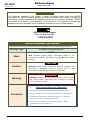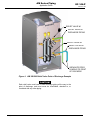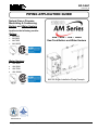
1
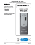
GF-146-P
TAG-0074_0B
PIPING APPLICATION GUIDE
Natural Gas or Propane
Modulating & Condensing
Boilers and Water Heaters
Applies to the following models:
Boilers
•
•
•
•
399 / 500 / 750 / 1000
AM 399B
AM 500B
AM 750B
AM 1000B
Gas-Fired Boilers and Water Heaters
Pending
Water Heaters
•
•
•
•
AM 399W
AM 500W
AM 750W
AM 1000W
AM 399 Single-Installation Piping Example
Pending
04/08/2014
Page 1 of 30
AERCO International, Inc. • 100 Oritani Dr. • Blauvelt, New York 10913 • Phone: 800-526-0288
PR1 04/08/2014
AM Series Piping
GF-146-P
Application Guide
TAG-0074 0B
DISCLAIMER
The information contained in this manual is subject to change without notice from AERCO
International, Inc. AERCO makes no warranty of any kind with respect to this material, including, but
not limited to, implied warranties of merchantability and fitness for a particular application. AERCO
International is not liable for errors appearing in this manual, nor for incidental or consequential
damages occurring in connection with the furnishing, performance, or use of these materials.
AERCO Technical Support:
(Mon–Fri, 8am-5pm EST)
1 (800) 526-0288
AERCO Document Conventions
In this document, some types of information are presented as shown in the following examples:
Message Type
Example and Description
Notes
NOTE messages indicate specific information related to the
surrounding contextual information, and highlighted for special
attention.
NOTE
CAUTION!
Cautions
CAUTION messages inform of potential problems relating to the
functioning of equipment, safety to persons, harm to the
environment, and/or damage to property or equipment.
WARNING!
Warnings
WARNING messages warn of potential dangerous situations that
may result in serious injury and/or death to persons or animals.
Text is red within a red box.
How Instructions are Presented
1. Instructions are shown in a blue box with an underlined title.
Instructions
2. All text, excepting in accompanying illustrations, is colored blue.
3. All procedures are listed in steps starting with “1.” and using
letters [a), b), c), etc.] indicating sub=steps.
4. Steps that are continued on the next page have a “(Cont.)”
appended to the instruction title.
Page 2 of 30
AERCO International, Inc. • 100 Oritani Dr. • Blauvelt, New York 10913 • Phone: 800-526-0288
PR1 04/08/2014
AM Series Piping
Application Guide
GF-146-P
TAG-0074 0B
Table of Contents
Table of Contents ..................................................................................... 3
1.
MANDATORY REQUIREMENTS ........................................................ 4
2.
BOILER QUALITY AND MAINTENANCE........................................... 6
2.1.
BOILER WATER CHEMISTRY ........................................................................ 6
2.1.1. Scale and Corrosion .......................................................................................6
2.1.2. Make-up or Feed Water Quality ....................................................................6
2.1.3. Treating Water to Prevent Freezing ...............................................................6
2.1.4. Water Treatment Certification .......................................................................6
2.2.
TESTING AND MAINTENANCE OF WATER QUALITY .................................. 6
2.3.
SYSTEM FLUSHING, TREATMENT, AND CLEANSING ................................ 8
2.3.1. System Flushing Recommendations ..............................................................8
2.3.2. Water Quality Maintenance and Boiler Warranty .........................................9
2.3.3. Water Treatment Certification ..................... Error! Bookmark not defined.
2.3.4. Water Treatment Analysis and Scheduling ...................................................9
2.4.
PRIMARY PUMP ............................................................................................ 11
2.5.
STRAINERS ................................................................................................... 15
2.6.
ISOLATION VALVES ..................................................................................... 15
2.7.
AIR VENTING OF THE HEATING SYSTEM (Boilers Only) .......................... 16
3.
CSD-1 MANIFOLD ASSEMBLY (SUPPLIED) ......Error! Bookmark not
defined.
4.
5.
CONNECTIONS ............................................................................... 19
4.1.
PRIMARY-SECONDARY PIPING .................................................................. 19
4.2.
SYSTEM FILLING AND DRAINING ............................................................... 19
4.3.
CONDENSATE DRAIN ................................................................................... 19
PIPING DIAGRAMS ......................................................................... 21
Page 3 of 30
AERCO International, Inc. • 100 Oritani Dr. • Blauvelt, New York 10913 • Phone: 800-526-0288
PR1 04/08/2014
AM Series Piping
GF-146-P
Application Guide
TAG-0074_0B
1.
MANDATORY REQUIREMENTS
The following are mandatory actions required to ensure proper piping and drainage of the AM Series
system.
CAUTION!
Local codes and authorities should be consulted prior to installation.
•
AERCO requires that the boiler loop to be de-coupled from the system loop. This can be achieved
by one of the following:
o
Employing primary-secondary piping.
o
Installation of a hydraulic separator between the boiler and the system loop.
o
Installation of a heat exchanger (for example, plate heat exchanger) between the boiler and
the system loop.
•
For water heating installations, a storage tank provides the required de-coupling.
•
AERCO requires cleaning of the whole system and to fit a mandatory Y-strainer on the return pipe
to the boiler, equipped with isolation valves (See Figures 11 to 18 at the end of this document).
•
For boiler replacement installations, cleaning of the whole system is required before connecting
the boiler (See Section 2.3 for Flushing, Treatment, and Cleansing tips and guidelines). Failure to
clean a system will limit it from the full benefits offered by the high efficiency AM Series.
•
Boiler drain valve and condensate neutralizer drain should be arranged to permit the fluids to drain
freely, by gravity, to a convenient floor drain.
•
For units installed in environments likely to experience freezing temperatures, it is necessary to
ensure that the condensate line and exhaust manifold are equipped with suitable freeze
protection, such as a heat trace line or insulation.
•
Relief valve must be installed vertically in the top, side, or to a valveless header connected to the
water supply outlet.
•
All piping and electrical connections (i.e. service switches, conduit boxes, etc.) should be located
at a minimum of 6 inches from the boiler panels and covers.
•
See Table 1 (Section 2) for sizing guidelines for the mandatory primary pump and boiler strainer.
•
A discharge pipe must be used and must not have an internal cross-sectional area less than the
outlet of the relief valve.
•
The discharge pipe must be installed so that there will be no danger of scalding to the boiler
attendants. See Figure 1 for a discharge pipe example of an AM Series unit.
•
The relief valve point of discharge piping must have provisions for proper drainage.
Page 4 of 30
AERCO International, Inc. • 100 Oritani Dr. • Blauvelt, New York 10913 • Phone: 800-526-0288
PR1 04/08/2014
AM Series Piping
GF-146-P
Application Guide
TAG-0074 0B
RELIEF VALVE #1
RELIEF VALVE #1
DISCHARGE PIPING
RELIEF VALVE #2
RELIEF VALVE #2
DISCHARGE PIPING
SEPARATE PIPES
LEADING TO POINT
OF DISCARGE
Figure 1: AM 399/500 Relief Valve Point of Discharge Example
CAUTION!
Each relief valve must have its own discharge piping all the way to the
point of discharge, and must never be manifolded, attached to, or
combined with any other piping.
Page 5 of 30
AERCO International, Inc. • 100 Oritani Dr. • Blauvelt, New York 10913 • Phone: 800-526-0288
PR1 04/08/2014
AM Series Piping
GF-146-P
Application Guide
TAG-0074 0B
2.
BOILER QUALITY AND MAINTENANCE
2.1. BOILER WATER CHEMISTRY
2.1.1. Scale and Corrosion
Free oxygen can cause the formation of rust (iron oxides), which degrade metallic materials.
Magnetite is formed in un-inhibited water if there is electrolytic action in the presence of oxygen.
Sludge is formed when calcium compounds, primarily CaCO3, are heated. Rust and magnetite, when
combined with sludge, can form a very hard scale, which significantly reduces system efficiency and
life expectancy of the heating system. Scale reduces heat exchange due to its low heat conductivity
and so may cause very dangerous localized overheating. Waterside corrosion of all heating circuit
surfaces is also a major concern.
2.1.2. Make-up or Feed Water Quality
Make-up or feed water is water added to a closed hydronic system to replenish water lost through
evaporation, maintenance, or leakage. The quality of make-up or feed water, which may contain
dissolved oxygen, minerals and other dissolved contaminants, is extremely important. Such
introduced water must be chemically treated or strictly limited when ensuring neutral chemical
conditions in boiler system water. Generally, any closed hydronic heating system should be restricted
from receiving untreated makeup water of no more than 5% of the total volume of system water per
year.
2.1.3. Treating Water to Prevent Freezing
When using anti-freeze solutions, their compatibility with the AM Series 316 (Ti) heat exchanger and
other components of the heating system must be determined prior to use. If a glycol solution is used
as anti-freeze protection, a backflow preventer must be installed upstream of the fill/makeup valve.
Only virgin glycol should be used for systems requiring freeze protection, and it must be treated with
an inhibitor compatible with the particular chemical treatment being used in the system. Note that
glycol must be changed from time to time due to its limited useful life.
Use only inhibited propylene glycol solutions, formulated for hydronic systems. Ethylene glycol is toxic
and can attack gaskets and seals used in hydronic systems.
2.1.4. Water Treatment Certification
When using chemical treatments in hydronic systems, it is necessary to ensure that the chosen
treatment is appropriate and certified by the manufacturer for such environments. The manufacturer
should also guarantee that the treatment, when applied according to the manufacturer’s
recommendations, will not cause harm to the boiler, pumps, piping, and other components of the
hydronic boiler system.
2.2. TESTING AND MAINTENANCE OF WATER QUALITY
Water in the installation should be checked, monitored, and treated for the following conditions and
characteristics:
•
Hardness – High hardness of the available water is measured in grains of hardness and
indicates the quantity of minerals (mostly calcium and magnesium) which are dissolved in the
water. Hardness substantially contributes to the formation of scaling, which is highly undesirable.
The total hardness must be less than 350 ppm total dissolved solids (TDS).
•
Artificial Softness – Do NOT use artificially softened water. Artificial softening agents generally
use salt, which creates a chloride water chemistry, a major contributor to the corrosion of the
Page 6 of 30
AERCO International, Inc. • 100 Oritani Dr. • Blauvelt, New York 10913 • Phone: 800-526-0288
PR1 04/08/2014
AM Series Piping
Application Guide
GF-146-P
TAG-0074 0B
types of metals used in hydronic systems. Elevated salt levels also contribute to higher
conductivity levels, another undesirable characteristic in hydronic systems.
•
Chloride – Chlorides are salts resulting from the combination of the gas chlorine with a metal and
are instrumental in accelerating corrosion in the types of metals used in hydronic systems.
Chlorides may be introduced into the water naturally. Concentrations of chlorides in system water
should be less than 150 ppm.
•
Conductivity – Dissolved metals and minerals increase the conductivity of water and indicate not
only the presence of undesired corrosive agents, but also contribute to the transfer and migration
of ions and charged particles in the water that contribute to fouling of sensors, valves, and other
devices used in the system. Additionally, high conductivity contributes to galvanic corrosion, in
which one metal will preferentially corrode when in contact with another type of metal, when both
are in contact with an electrolyte. Conductivity should be less than 3000 μS.
•
pH – The pH, a measure of the acidic, neutrality, and alkalinity of the water, must always be
between 7.5 and 9.5 pH.
•
Oxygen – All precautions should be taken to avoid the formation and localization of oxygen in the
water of a heating system. Water that is low in minerals (soft water) absorbs oxygen much more
readily than mineralized (hard) water. For this reason it is necessary that in heating systems
using floor radiant heating, the plastic pipes used be impermeable to oxygen.
•
Scale and Corrosion – The use of an inhibitor is advisable to treat feed and make-up water and
to protect heating systems against scale, corrosion and microbiologic growth. To prevent
freezing, the use of an anti-freezing agent together with the inhibitor is advisable. Qualified
companies can also provide boiler de-scaling.
•
Water treatment is also advisable in the following cases:
o
Very large heating systems
o
High quantities of replenished water due to leakages or maintenance work
Page 7 of 30
AERCO International, Inc. • 100 Oritani Dr. • Blauvelt, New York 10913 • Phone: 800-526-0288
PR1 04/08/2014
GF-146-P
TAG-0074 0B
AM Series Piping
Application Guide
2.3. SYSTEM FLUSHING, TREATMENT, AND CLEANSING
Note that prior to cleaning the heating system, the boiler MUST be isolated from the piping to
prevent infusion of containments, including sludge, into the boiler. Section 2.3 provides
recommendations for flushing, cleaning, and treating the water used in the AM Series system.
IMPORTANT!
Cleaning solution and inhibitors used must be compatible with
heat exchanger material.
Corrosion/scale inhibitor will be
ineffective if added to a dirty system; therefore, it is very important
to clean the system first.
AERCO recommends the following cleaning solution, inhibitor, and antifreeze products.
www.aerco.com for Product Fact sheet and Material Safety Data Sheets:
•
•
Visit
Water Quality Testing — X100 Quick Test Kit
Part number 99152-1
Corrosion/Scale Inhibitor — Sentinel X100 Liquid Inhibitor
4 x 1 gallon case – part number 99153-2
5 gallon jug – part number 99153-1
•
Boiler Noise Reducer — Sentinel X200 Liquid Noise Inhibitor
4 x 1 gallon case – part number 99154-2
5 gallon jug – part number 99154-1
•
System Cleaner — Sentinel X300 Liquid System Cleaner
4 x 1 gallon case – part number 99199-2
5 gallon jug – part number 99199-1
•
Cleaning solution — Sentinel X400 Liquid System Restorer
4 x 1 gallon case – part number 99155-2
5 gallon jug – part number 99155-1
•
Antifreeze — Sentinel X500 Liquid Inhibited Antifreeze
5 gallon jug – part number 99156-1
55 gallon jug – part number 99156-2
275 gallon tote – part number 99156-3
When cleaning, treating, and maintaining, a heating system, consult a qualified professional. The
following are AERCO’s tips/guidelines for cleaning a heating system – these do NOT take precedence
over detailed instructions from qualified professionals.
2.3.1. System Flushing Recommendations
•
Make sure to use an appropriate amount of cleaning solution, carefully following the
manufacturer’s instructions. Follow the chemical manufacturer’s recommendations when
introducing cleaning agents into the system.
•
Ensure that the cleaning solution is circulated thoroughly in the system.
•
Flush the system thoroughly to remove the maximum amount of contaminants. When emptying
the system, make sure it is done as quickly as possible using all drain off points and ensuring all
Page 8 of 30
AERCO International, Inc. • 100 Oritani Dr. • Blauvelt, New York 10913 • Phone: 800-526-0288
PR1 04/08/2014
AM Series Piping
Application Guide
low lying pipework is fully drained.
completely emptied.
GF-146-P
TAG-0074 0B
Opening all bleed valves ensures the system will be
•
A reliable test to determine if a system is clean is if the Total Dissolved Solids (TDS) of the water
being drained is within 10% of the make-up water TDS. This indicates that sufficient
contamination has been flushed from the system. If the difference in TDS is more than 10%, it is
recommended to repeat the cleaning process until that is achieved. A turbidity test can be used
as an alternate way to determine if a system is clean.
•
For boiler retrofit/replacement installation, it will be necessary to repeat the cleaning process until
the draining water appears to be clear. Once clear, the above TDS comparison (or a turbidity test)
should be performed.
•
If a flushing machine is used in the cleaning process, carefully follow the manufacturer’s
instructions. If the flushing machine is designed to flush individual zones, the TDS comparison
must be made between each zone and the make-up water, or the turbidity test performed for each
zone.
•
Add corrosion and scale inhibitor after the system has been declared clean, using the appropriate
amount recommended by the manufacturer. Introduce the protector/scale inhibitor to the system
following the chemical treatment manufacturer’s instructions. Adding inhibitor to a dirty system
reduces its effectiveness.
When refilling the system, ensure the boiler is not air-bound by opening the pressure-relief valve
located at the rear of the boiler. Leave the relief valve open until a steady flow of water is observed.
Close the valve and finish filling the system.
2.3.2. Water Quality Maintenance and Boiler Warranty
Heat exchanger failures due to improperly cleaned/treated and poorly maintained water are not
covered under warranty. Scheduled system/boiler water maintenance is required to maintain the heat
exchanger warranty. AERCO shall reserve the right to require maintenance records when evaluating
warranty claims.
2.3.3. Water Treatment Analysis and Scheduling
The proper mixture of water, chemical treatment, and glycol (if used) should be ascertained based on
a sample of the system water and the make-up water. Your local water treatment company, or one of
the manufacturers listed below, may analyze your sample. Adjust the chemical composition of your
system water based on the analysis. After this initial analysis, the chemical composition of your
system water should be tested at the beginning of each heating season. For boilers operating year
round, this analysis should be made at least twice a year.
2.3.4. Boiler Loop Design Guidelines
For proper and safe operation of the water tube AM boiler, the primary (boiler) loop piping and the
associated fittings and accessories must be designed/selected as discussed in the following sections.
Table 1 shows the required minimum flow rates at various system designed temperature rises. Also
shown are pressure drops through strainers typically needed in the boiler loop (see paragraph 4.2 for
strainer requirement details).
The following primary/secondary piping design guidelines should be used for AM Series installations.
The data was calculated based upon systems with Return Water Temperatures above 80°F. A 20
mesh strainer (or finer) is required at each boiler inlet. Water flow rates and pressure drops shown
below are for the boiler loop. Boiler water flow rates vary with system design parameters. The boiler
loop fittings and strainer pressure drops shown below are examples only – actual pressure
drops will vary depending on actual piping layout and strainer size/type used.
Page 9 of 30
AERCO International, Inc. • 100 Oritani Dr. • Blauvelt, New York 10913 • Phone: 800-526-0288
PR1 04/08/2014
AM Series Piping
GF-146-P
Application Guide
TAG-0074 0B
TABLE 1: Flow Rate and Pressure Drops
AM 399
AM 500
AM 750
AM 1000
Minimum Water Flow (GPM) @ Min. Fire Rate
4
4
4
4
Minimum Water Flow (GPM) @ Max. Fire Rate
7
9
14
18
Maximum Water Flow (GPM)
37
37
55
74
Water Pressure Drop (Ft. of Hd.) at Max. Flow
29
55
41.5
38
14.7
18.4
27.6
36.8
5
17
13
10.5
1-1/4" NPT
1-1/2"
NPT
1-1/2" NPT
2" NPT
Strainer ∆P (Ft. of Hd.) – (‘Y’ Strainer, 20 mesh)
0.63
0.54
1.22
0.64
∆P (Ft. of Hd.) – (20’ SCH.40, 4 x 90°, 2 x
reducing
couplings, 2 x Ball Valve)
1.28
1.03
2.37
1.22
Total Primary Loop ∆P (Ft. of Hd.) @ ∆T of
50°F
6.91
18.57
16.59
12.36
Water Flow (GPM) @ 40°F ∆T
18.4
23.0
34.5
46.0
Water Pressure Drop (Ft. of Hd.) @ 40°F ∆T
Flow
7.5
25
18.5
15
1-1/4" NPT
1-1/2"
NPT
2" NPT
2" NPT
Strainer ∆P (Ft. of Hd.) – (‘Y’ Strainer, 20 mesh)
0.99
0.85
0.56
1.00
∆P (Ft. of Hd.) – (20’ SCH.40, 4 x 90°, 2 x
reducing
couplings, 2 x Ball Valve)
2.89
1.64
1.11
1.74
Total Primary Loop ∆P (Ft. of Hd.) @ ∆T of
40°F
11.38
27.48
20.17
17.73
24.5
30.7
46.0
61.3
13
39
30
27
1-1/2" NPT
2" NPT
2" NPT
2" NPT
0.96
0.44
1.00
1.77
∆P (Ft. of Hd.) – (20’ SCH.40, 4 x 90°, 2 x
reducing couplings, 2 x Ball Valve)
1.76
0.75
1.74
3.11
Total Primary Loop ∆P (Ft. of Hd.) @ ∆T of 30°F
15.72
40.19
32.73
31.88
@ 25°F
Water Flow (GPM) @ Min. ∆T of 25°F
Water Pressure Drop (Ft. of Hd.) at Max. Flow
29.4
19
36.8
55
55.2
41.5
73.6
38
@ 50°F
Water Flow (GPM) @ Max. ∆T of 50°F
Water Pressure Drop (Ft. of Hd.) at Min. Flow
Strainer, Pipes, Valves and Fittings Size
@ 40°F
Strainer, Pipes, Valves and Fittings Size
@ 30°F
Water Flow (GPM) @ 30°F ∆T
Water Pressure Drop (Ft. of Hd.) @ 30°F ∆T
Flow
Strainer, Pipes, Valves and Fittings Size
Strainer ∆P (Ft. of Hd.) – (‘Y’ Strainer, 20 mesh)
Page 10 of 30
AERCO International, Inc. • 100 Oritani Dr. • Blauvelt, New York 10913 • Phone: 800-526-0288
PR1 04/08/2014
AM Series Piping
GF-146-P
Application Guide
TAG-0074 0B
TABLE 1: Flow Rate and Pressure Drops
AM 399
AM 500
AM 750
AM 1000
1-1/4" NPT
1-1/2"
NPT
2" NPT
2" NPT
Strainer ∆P (Ft. of Hd.) – (‘Y’ Strainer, 20 mesh)
0.41
0.64
0.70
1.25
∆P (Ft. of Hd.) – (20’ SCH.40, 4 x 90°, 2 x
reducing
couplings, 2 x Ball Valve)
0.71
1.21
0.92
1.76
Total Primary Loop ∆P (Ft. of Hd.) @ ∆T of
25°F
20.12
56.85
43.13
41.01
Strainer, Pipes, Valves and Fittings Size
NOTE: A reducing coupling is not used where boiler line size matches outlet size.
2.4. PRIMARY PUMP
The primary pump shall have a discharge pressure able to assure the designed water flow rate, taking
into account pressure drop losses as shown in Figure 2. When selecting a pump, take into account
the pressure drop across the unit, fittings, accessories, and piping. The primary pump electrical
connection shall be made as shown in Figure 4 for boilers and Figure 5 or 6 for water heaters (terminals 113
and 114).
Pumps shall be calculated by installers or engineers according to boiler and system parameters. The
pump is not an integral part of the boiler.
•
If water is between 5 and 8 grains, water is soft, and must have a minimum velocity of 4 ft/sec.
See Table 1.
•
If water is between 9 and 17 grains, water is normal, and flow should be between 4-8 ft/sec.
•
If water is between 18 and 23 grains, water is hard, and must have a minimum velocity of 8
ft/sec.
NOTE
Select the pump flow rate so that the boiler water outlet temperature is
190°F (87.8°C) or below.
Page 11 of 30
AERCO International, Inc. • 100 Oritani Dr. • Blauvelt, New York 10913 • Phone: 800-526-0288
PR1 04/08/2014
GF-146-P
TAG-0074 0B
AM Series Piping
Application Guide
Figure 2: Water Side Pressure Loss Chart
Figure 3: Water Velocity Flow Chart
Page 12 of 30
AERCO International, Inc. • 100 Oritani Dr. • Blauvelt, New York 10913 • Phone: 800-526-0288
PR1 04/08/2014
AM Series Piping
Application Guide
GF-146-P
TAG-0074 0B
Figure 4: AM BOILER: Electrical Connections
Page 13 of 30
AERCO International, Inc. • 100 Oritani Dr. • Blauvelt, New York 10913 • Phone: 800-526-0288
PR1 04/08/2014
GF-146-P
TAG-0074 0B
AM Series Piping
Application Guide
Figure 5: Water Heater Electrical Junction Box Connections
(with Small Storage Tank)
Figure 6: Water Heater Electrical Junction Box Connections
(with Large Storage Tank)
Page 14 of 30
AERCO International, Inc. • 100 Oritani Dr. • Blauvelt, New York 10913 • Phone: 800-526-0288
PR1 04/08/2014
AM Series Piping
Application Guide
GF-146-P
TAG-0074 0B
2.5. STRAINERS
AERCO requires the installation of a Y strainer to keep dirt out of the system and boiler. The strainer
should be installed in the return piping with isolation valves to allow for cleaning as necessary. The Y
strainer shall have a 20 mesh or finer strainer. Such filter shall protect the boiler from heating system
dirt. It should be regularly cleaned to prevent problems.
2.6. ISOLATION VALVES
It is MANDATORY that ball or other type of shut-off valves be installed in the system supply and
return piping to isolate the boiler if necessary. In this case the boiler can be disconnected or drained
without having to drain the whole system.
WARNING!
NEVER bypass safety devices, such as safety valves and expansion
vessels.
Page 15 of 30
AERCO International, Inc. • 100 Oritani Dr. • Blauvelt, New York 10913 • Phone: 800-526-0288
PR1 04/08/2014
AM Series Piping
GF-146-P
Application Guide
TAG-0074 0B
2.7. AIR VENTING OF THE HEATING SYSTEM
The AM Series units come standard with automatic air vents on each of the headers on the rear of the
unit (see Figure 6a and 6b). These vents are for the unit only and not the entire heating system. An
effective air vent for air removal for the entire heating system must be installed in the highest point of
the system piping.
AUTOMATIC AIR
VENTS
SAFETY RELIEF VALVE
PRESSURE AND
TEMPERATURE GAUGE
HEADER
TEMPERATURE
SENSOR
WATER SUPPLY
(OUTLET) CONNECTION
HEADERS
WATER RETURN
(INLET) CONNECTION
DRAINING VALVES
Figure 6a: AM 399/500 Rear Panel Connections
Page 16 of 30
AERCO International, Inc. • 100 Oritani Dr. • Blauvelt, New York 10913 • Phone: 800-526-0288
PR1 04/08/2014
AM Series Piping
Application Guide
GF-146-P
TAG-0074 0B
AUTOMATIC AIR
VENTS
SAFETY RELIEF VALVE
PRESSURE AND
TEMPERATURE GAUGE
HEADER
TEMPERATURE
SENSOR
WATER SUPPLY
(OUTLET) CONNECTION
HEADERS
WATER RETURN
(INLET) CONNECTION
DRAINING VALVES
Figure 6b: AM 750/1000 Rear Panel Connections
Page 17 of 30
AERCO International, Inc. • 100 Oritani Dr. • Blauvelt, New York 10913 • Phone: 800-526-0288
PR1 04/08/2014
AM Series Piping
GF-146-P
Application Guide
TAG-0074 0B
2.3.5. Flow Switch
A flow switch is required to be installed on every unit (Figure 7). This flow switch is included with the
unit and must be field-installed.
The flow switch should be installed in a tee on the boiler outlet piping as shown in Figure 7. The
paddle of the flow switch may have to be cut to length for the given pipe diameter according to the
manufacturer’s instructions. You must NOT install any valves in between the unit and the flow switch.
FLOW
SWITCH
FLOW SWITCH
BOILER OUTLET
PIPING
FLOW
SWITCH
PADDLE
Figure 7: Supplied Flow Switch (L) and Installation Location (R) Example
2.3.6. Low Water Cutoff (LWCO)
If a low water cutoff (LWCO) is preferred (Figure 8), one may be installed in place of, or in addition to,
the flow switch. This is available as an accessory from AERCO. When installing such a device, you
must consult and abide by all local codes and regulations in force.
Figure 8: Optional Low Water Cutoff (LWCO)
NOTE
Use Teflon tape or a suitable pipe joint compound for component and
piping connections.
Page 18 of 30
AERCO International, Inc. • 100 Oritani Dr. • Blauvelt, New York 10913 • Phone: 800-526-0288
PR1 04/08/2014
AM Series Piping
Application Guide
3.
GF-146-P
TAG-0074 0B
CONNECTIONS
3.1. PRIMARY-SECONDARY PIPING
Primary-secondary piping must be utilized. This can be accomplished by using a common pipe (see
Figures 11, 13, 15, 17) or a hydraulic separator. Primary – secondary piping decouples the boiler loop
from the system loop, making it independent from system loop pressure fluctuations associated with
opening/closing of zone valves or 3-way valves.
3.2. SYSTEM FILLING AND DRAINING
The boiler is equipped with its own header drains (see Figures 6a and 6b for the drain locations).
NEVER USE IT TO DRAIN THE ENTIRE SYSTEM, since the system dirt could gather in the boiler
and compromise its operation. The system itself shall be equipped with its own drain, whose size will
depend on the system capacity.
•
For filling the system, a filling tap has to be inserted on the system return pipe.
•
The filling can also be done through the draining tap on the boiler return manifold
(see drain valve locations in Figure 6a and Figure 6b).
•
In both cases, an approved hydraulic disconnection system has to be fitted.
•
Before connecting the boiler, carefully rinse out the whole system, as specified in Section 2.3 or
by local code and best practices.
3.3. CONDENSATE DRAIN
To maintain proper flow of condensate the drain pipe must have a slope toward the drain of at least
3/8 in./ft. (30 mm/m). In order to prevent ice from forming, the condensate piping must be well
insulated.
Figure 9: Typical Condensate Drain Installation
Page 19 of 30
AERCO International, Inc. • 100 Oritani Dr. • Blauvelt, New York 10913 • Phone: 800-526-0288
PR1 04/08/2014
GF-146-P
TAG-0074 0B
AM Series Piping
Application Guide
The AM Series of boilers and water heaters come equipped with a condensate trap and neutralizer
tank (see Figure 10). It is crucial that these be filled with water to prevent combustion gases from
entering the room and/or gases flowing backwards through the condensate line. A corrugated tube is
provided to pipe neutralized condensate to a drain. It may be necessary to add additional piping to the
condensate removal system in order to reach an appropriate drain.
Figure 10: Condensate Drain Assembly Components
WARNING!
The condensate collection box must be filled with water to prevent flue
gas emissions from escaping during unit operation. Failure to comply
with this requirement can result in dangerous levels of carbon monoxide
and other dangerous gases.
Page 20 of 30
AERCO International, Inc. • 100 Oritani Dr. • Blauvelt, New York 10913 • Phone: 800-526-0288
PR1 04/08/2014
AM Series Piping
Application Guide
4.
GF-146-P
TAG-0074 0B
PIPING DIAGRAMS
NOTES
1) For actual sizes and locations of piping and other connections to
the boiler, see appropriate dimensional drawing.
2) Drain valve and condensate drain hose should be arranged to
permit the fluids to drain freely by gravity to a convenient floor
drain. The relief valve should be piped vertically to a height 18"
above the floor.
3) All piping and electric connections (service switches, conduit
boxes, etc.) should be 6" away from side panels.
4) Mandatory: primary pump
5) Mandatory: boiler strainer (20 mesh or finer).
6) Recommended: Gas regulator (and is required when supply
pressure is greater than 13" W.C.)
7) All drawings are of typical installations. Local codes and
authorities should be consulted.
Page 21 of 30
AERCO International, Inc. • 100 Oritani Dr. • Blauvelt, New York 10913 • Phone: 800-526-0288
PR1 04/08/2014
GF-146-P
TAG-0074 0B
AM Series Piping
Application Guide
Figure 11: AM 399/500 Single Unit Installation
Page 22 of 30
AERCO International, Inc. • 100 Oritani Dr. • Blauvelt, New York 10913 • Phone: 800-526-0288
PR1 04/08/2014
AM Series Piping
Application Guide
GF-146-P
TAG-0074 0B
Figure 12: AM Series 399/500 Single Unit Installation
with DHW Installed
Page 23 of 30
AERCO International, Inc. • 100 Oritani Dr. • Blauvelt, New York 10913 • Phone: 800-526-0288
PR1 04/08/2014
GF-146-P
TAG-0074 0B
AM Series Piping
Application Guide
Figure 13: AM Series 399/500 Multiple Unit Installation
Page 24 of 30
AERCO International, Inc. • 100 Oritani Dr. • Blauvelt, New York 10913 • Phone: 800-526-0288
PR1 04/08/2014
AM Series Piping
Application Guide
GF-146-P
TAG-0074 0B
Figure 14: AM Series 399/500 Multiple unit Installation
With DHW Installed
Page 25 of 30
AERCO International, Inc. • 100 Oritani Dr. • Blauvelt, New York 10913 • Phone: 800-526-0288
PR1 04/08/2014
GF-146-P
TAG-0074 0B
AM Series Piping
Application Guide
Figure 15: AM 750/1000 Single Unit Installation
Page 26 of 30
AERCO International, Inc. • 100 Oritani Dr. • Blauvelt, New York 10913 • Phone: 800-526-0288
PR1 04/08/2014
AM Series Piping
Application Guide
GF-146-P
TAG-0074 0B
Figure 16: AM Series 750/1000 Single Unit Installation
with DHW Installed
Page 27 of 30
AERCO International, Inc. • 100 Oritani Dr. • Blauvelt, New York 10913 • Phone: 800-526-0288
PR1 04/08/2014
GF-146-P
TAG-0074 0B
AM Series Piping
Application Guide
Figure 17: AM Series 750/1000 Multiple Unit Installation
Page 28 of 30
AERCO International, Inc. • 100 Oritani Dr. • Blauvelt, New York 10913 • Phone: 800-526-0288
PR1 04/08/2014
AM Series Piping
Application Guide
GF-146-P
TAG-0074 0B
Figure 18: AM Series 750/1000 Multiple unit Installation
With DHW Installed
Page 29 of 30
AERCO International, Inc. • 100 Oritani Dr. • Blauvelt, New York 10913 • Phone: 800-526-0288
PR1 04/08/2014
AM Series Piping
GF-146-P
Application Guide
TAG-0074 0B
Change Log
Date
Description
Changed By
04/08/2014
Rev 0A: Release
Curtis Harvey
© AERCO International, Inc., 2014
www.aerco.com
Page 30 of 30
AERCO International, Inc. • 100 Oritani Dr. • Blauvelt, New York 10913 • Phone: 800-526-0288
PR1 04/08/2014