1
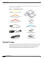
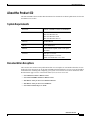
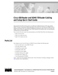
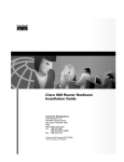
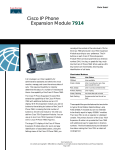
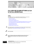
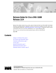
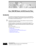
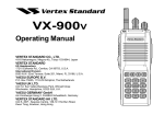
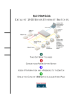
Cisco 800 Series Router Cabling and Setup
Quick Start Guide
This document describes the basic process of cabling and configuring the Internet access device, the
Cisco 800 series router. For advanced cabling information, refer to the Cisco 800 Series Router Hardware
Installation Guide. For advanced configuration information, refer to the Cisco 800 Series Router Software
Configuration Guide. These documents are available on the Cisco Documentation CD-ROM and on the
World Wide Web.
You can access the most current Cisco documentation on the World Wide Web at the following sites:
•
http://www.cisco.com
•
http://www-china.cisco.com
•
http://www-europe.cisco.com
Parts List
The shipment of your Cisco 800 series router includes the following items:
•
One Cisco 800 series router
•
One yellow Ethernet cable
•
One orange ISDN S/T cable (Cisco 801 and Cisco 803 only)
•
One red ISDN U cable (Cisco 802 and Cisco 804 only)
•
One RJ-45-to-RJ-11 adapter cable (for use with the red ISDN U cable)
•
One blue console cable
•
One DB-9-to-RJ-45 adapter (for use with the blue console cable)
•
One DB-25-to-RJ-45 adapter (for use with the blue console cable)
•
One black power supply
•
One black power supply cord
•
800 and SOHO Series Product Documentation CD
•
Cisco 800 Fast Step CD-ROM
Corporate Headquarters:
Cisco Systems, Inc., 170 West Tasman Drive, San Jose, CA 95134-1706 USA
Copyright © 2001. Cisco Systems, Inc. All rights reserved.
Verify the PC Setup
Figure 1 shows the items included with the router. If any of the items is missing or damaged, contact
your customer service representative.
Figure 1
Items Included with the Router
er ai
th nt
O e
um
oc
D
on
Yellow Ethernet cable
rt
ta
S
e
ck id
ui u
Q G
n
tio
ta
en OM
um -R
oc D
D C
Orange ISDN S/T cable
(Cisco 801 and Cisco 803)
Product documentation
0
80 p
e
co t
is S
C ast
F
Red ISDN U cable
(Cisco 802 and Cisco 804)
Cisco 800
Fast Step CD-ROM
RJ-45-to-RJ-11 adapter cable
(for use with red ISDN U cable)
Light blue console cable
Desktop power supply
DB-9-to-RJ-45 adapter
(for use with light blue console cable)
Black power cord
DB-25-to-RJ-45 adapter
(for use with light blue console cable)
Verify the PC Setup
Before you begin, verify that each computer that will be connected to the router has a network interface
card (NIC) installed and that Transmission Control Protocol/Internet Protocol (TCP/IP) has been loaded
and configured. For more information on how to configure TCP/IP, refer to the PC Configuration
Instructions to Establish Cisco Router-to-PC Communications, which is available on the Cisco
Documentation CD-ROM, and refer to information available the Microsoft web site.
Verify the PC Setup
2
78-5374-03
Connect the Cisco 800 Series Router to a PC
Connect the Cisco 800 Series Router to a PC
Follow these steps to connect the Cisco 800 series router to a PC:
Step 1
Connect the yellow Ethernet cable from the yellow Ethernet port (Cisco 801 and 802 routers) or from
the yellow Ethernet port with the number 0 (Cisco 803 and 804 routers) on the back panel of the router
to the Ethernet port on the NIC on the computer.
Figure 2
Connecting a Cisco 800 Series Router to a PC
HUB
NO HUB
Cisco 80
ETHERN
3
ET 10 BAS
ET
CONSO
LE
ISDN S/T
0
PHONE
1
2
3
1
2
Cisco 803 router
OK
SER 0
AUX
LAN
AUX
PC
Step 2
Note
Step 3
Caution
Verify that the HUB/NO HUB switch on the left side of the back panel has been set to the NO HUB
position (out). If the button is in, press it to set it to the out position.
The HUB/NO HUB button corresponds to the Ethernet port on Cisco 801 and 802 routers and to
Ethernet port 0 on Cisco 803 and 804 routers.
For Cisco 803 and 804 routers, connect additional computers to the Cisco 800 series router by
connecting Ethernet cables from the Ethernet ports labeled with the numbers 1, 2, and 3 to the Ethernet
ports on the computers.
Always connect the yellow cable or Ethernet cable that you supply to the yellow ports on the router.
Do not connect the cable to an ISDN S/T or U port or to a Network Termination 1 (NT1) device.
Accidently connecting the cable to the wrong port can damage your router.
Connect the Cisco 800 Series Router to a PC
78-5374-03
3
Connect the Cisco 800 Series Router to a Hub
Connect the Cisco 800 Series Router to a Hub
Follow these steps to connect the Cisco 800 series router to a hub:
Step 1
Connect the yellow Ethernet cable from the yellow Ethernet port (Cisco 801 and 802 routers) or from
the yellow Ethernet port with the number 0 (Cisco 803 and 804 routers) on the back panel of the router
to the Ethernet port on the hub.
Figure 3
Connecting a Cisco 800 Series Router to a Hub
HUB
NO HUB
Cisco 80
ETHERN
3
ET 10 BAS
ET
CONSO
LE
ISDN S/T
0
PHONE
1
2
3
Cisco 803 router
1
2
1X
2X
SPEED
LED
100Bas
eTX SO
LID
10Base
T BLI
NK
10/100
3X
4X
1 2 3
4
5 6 7
8
5X
6X
7X
8X
MDI
MDI-X
Cisco 1528 Micro Hub 10/100
Step 2
Note
Caution
Verify that the HUB/NO HUB switch on the left side of the back panel has been set to the HUB position
(in). If the button is out, press it to set it to the in position.
The HUB/NO HUB button corresponds to the Ethernet port on Cisco 801 and 802 routers and to
Ethernet port 0 on Cisco 803 and 804 routers.
Always connect the yellow cable or Ethernet cable that you supply to the yellow ports on the router.
Do not connect the cable to an ISDN S/T or U port or to a Network Termination 1 (NT1) device.
Accidently connecting the cable to the wrong port can damage your router.
Connect the Cisco 800 Series Router to a Hub
4
78-5374-03
Connect an ISDN Line
Connect an ISDN Line
Refer to the section corresponding to your router model and follow the steps to connect the
Cisco 800 series router to an ISDN line.
Caution
•
Option A—Connecting Cisco 801 and Cisco 803 Routers
•
Option B—Connecting Cisco 802 and Cisco 804 Routers
Always connect the orange cable to the orange ISDN S/T port and the red cable to the red ISDN U
port on the router. Do not connect either cable to the yellow Ethernet port. Accidently connecting
these cables to the wrong port can damage your router.
Option A—Connecting Cisco 801 and Cisco 803 Routers
This section describes how to connect Cisco 801 and Cisco 803 routers outside of North America. For
information on connecting these routers in North America, see the Cisco 800 Series Routers Hardware
Installation Guide.
Figure 4
Connecting an 801 or 803 Router to an ISDN Line
HUB
NO HUB
Cisco 80
ETHERN
3
ET 10 BAS
ET
CONSO
LE
ISDN S/T
0
PHONE
1
2
3
1
2
Cisco 803 router
ISDN wall jack
Step 1
Connect the orange cable to the orange ISDN S/T port.
Step 2
Connect the other end of the cable to the ISDN wall jack.
Connect an ISDN Line
78-5374-03
5
Connect Telephone, Fax Machine, or Modem
Option B—Connecting Cisco 802 and Cisco 804 Routers
Figure 5
Connecting an 802 or 804 Router to an ISDN Line
HUB
NO HUB
Cisco 80
ETHERN
4
ET 10 BA
SE T
CONSO
LE
ISDN U
0
PHONE
1
2
Cisco 804 router
3
1
2
ISDN wall jack
RJ-45-to-RJ-11
adapter cable
Step 1
Connect the red cable to the red ISDN U port.
Step 2
Connect the other end of the cable to the ISDN wall jack. If your wall jack has an RJ-11 connector,
attach the RJ-45-to-RJ-11 adapter cable to the red cable, and then connect the RJ-11 connector to the
ISDN wall jack.
Connect Telephone, Fax Machine, or Modem
If you have a Cisco 803 or Cisco 804 router, you can connect a touch-tone telephone, fax machine, or
modem. Use the cables provided with these devices.
The gray PHONE 1 and PHONE 2 ports are RJ-11 connectors. If you are outside of North America, you
must buy and attach adapters that allow your telephones, faxes, or modems to be connected to these
RJ-11 connectors. In some countries, these adapters need additional electronics to convert the
telephones, faxes, or modems to work properly with the router phone ports. For example, in the United
Kingdom, you must buy an adapter that also provides a master socket, which causes incoming calls to
ring the connected devices. For information on recommended master sockets, see the Cisco 800 Series
Routers Hardware Installation Guide.
Caution
Do not connect the router telephone ports to the telephone wall jack. These ports are not meant for
direct connection to the public network. This connection can damage your router.
Option B—Connecting Cisco 802 and Cisco 804 Routers
6
78-5374-03
Connect the Power and Turn On the Router
Figure 6
Connecting an 800 Series Router to a Telephone
HUB
NO HUB
Cisco 80
ETHERN
4
ET 10 BAS
ET
CONSO
LE
ISDN U
0
PHONE
1
2
3
Cisco 804 router
1
2
Analog telephone
Step 1
Connect one end of the telephone cable to the gray PHONE 1 or PHONE 2 port. If you are connecting
only one device, use the PHONE 1 port.
Step 2
Connect the other end of the cable to your device.
Connect the Power and Turn On the Router
Follow these steps to connect power to the Cisco 800 series router and turn it on:
Figure 7
Connecting the Power to an 800 Series Router
HUB
NO HUB
Cisco 80
ETHERN
3
ET 10 BAS
ET
CONSO
LE
ISDN S/T
0
PHONE
1
2
3
1
2
To electrical outlet
Desktop power supply
Connect the Power and Turn On the Router
78-5374-03
7
Verifying the LEDs
Step 1
Make sure the router power is off. Press the power switch to standby (
Step 2
Connect the power supply cable to the 8-pin connector on the router.
Step 3
Connect the power cord to the desktop power supply.
Step 4
Connect the other end of the power cord to an electrical outlet.
Step 5
Turn ON the router. Press the power switch to on (|).
).
Verifying the LEDs
Verify the power connection and all other connections (links) by checking the LEDs in the table below.
If the LEDs are not on, see the troubleshooting information in the Cisco 800 Series Routers Hardware
Installation Guide.
Power/Link
LEDs To Check
Normal Patterns
Power
OK
On
To hub, server, PC, or
workstation
Cisco 801 or Cisco 802 back panel:
LINK LED
On
Cisco 803 or Cisco 804 front panel:
LKØ, LK1, LK2, and LK3 LEDs
To ISDN network using
ISDN S/T port
LINE, CH1, or CH2
On. CH1 or CH2 is on only
when the router has an active
voice or data connection.
To ISDN network using
ISDN U port
NT1, LINE, CH1, or CH2
On. CH1 or CH2 is on only
when the router has an active
voice or data connection.
To telephone, fax, or
modem
PH1 or PH2
On. PH1 or PH2 is on only
when telephone, fax, or
modem is in use.
You can also pick up the handset and
listen for a dial tone.
Verifying the LEDs
8
78-5374-03
About the Product CD
About the Product CD
The 800 and SOHO Series Product Documentation CD contains the technical publications for the 800
and SOHO series routers.
System Requirements
Processor
Pentium 150 MHz or faster recommended
PC OS
Microsoft Windows 95
Microsoft Windows 98
Microsoft Windows 2000
Microsoft Windows NT 4.0
Memory
64-MB DRAM
Drives
4x CD-ROM drive
Monitor
Color monitor capable of 800 x 600 pixel
resolution
Software
Netscape 3.0 or later
Internet Explorer 3.0 or later
Adobe Acrobat Reader 3.0 or later
Documentation Exceptions
This CD does not contain certain publications that were incomplete or unavailable when this CD was
produced. These documents are in the 800 and SOHO platform hardware accessory kits and should be
consulted before installing and configuring your system. You can also access these documents on the
Documentation page on Cisco Connection Online (CCO) at www.cisco.com.
•
Cisco 800 Series Routers Release Notes
•
Cisco 828 and SOHO 78 Routers Release Notes
•
IOS Release Notes for the Cisco 800 Series Router
•
IOS Release Notes for the Cisco 828 Router
•
Cisco Router Web Setup User Guide
About the Product CD
78-5374-03
9
About the Product CD
Using the CD Interface
When the CD is first launched, it automatically opens a browser session and displays the CD interface
in the browser window. You can use the list of books in the left pane of your display to navigate directly
to the book you want to view. Within the interface, you can use your mouse to:
•
Hover over book titles in the left column for an overview of the document before opening a
document.
•
Select a book title from the document list on the left or from the document drop-down menu on the
CD title bar.
•
Click the Cisco Systems corporate icon to display Cisco support and service information.
•
Click About This CD (notepad icon) to get additional information about this CD.
•
Click Send Us Your Feedback! (pencil & notepad icon) to provide us with your feedback.
•
Click Get Acrobat Reader to install a free copy of Adobe Acrobat Reader 4.0.
Changing the Display Properties of Documents
When you first launch the CD, you will notice a list of books in the left pane of your display that you
can use to navigate directly to the book you want to view. When you select the document, Acrobat
Reader opens the book in .pdf format and provides a list of topics in the left frame of the Acrobat
window. To disable this option and view the book fully in the window, click the Show/Hide Navigation
Pane button on the Acrobat toolbar. Note that when hiding bookmarks, the thumbnails, annotations, and
articles are also hidden.
Printing Documents
To print a document:
Step 1
Click the Printer icon on the Acrobat toolbar.
The Windows Print Dialog box appears.
Step 2
Select your default printer and click OK.
Ordering Printed Copies of Documents
You can order printed copies of the documents on this CD and additional copies of this CD on the 800
and SOHO platform product ordering pages on Cisco Connection Online (CCO). Registered CCO users
can order documentation for other Cisco products and the Cisco Documentation CD-ROM (containing
all Cisco documentation) through our online Subscription Services at
http://www.cisco.com/cgi-bin/subcat/kaojump.cgi.
Nonregistered CCO users can order documentation through a local account representative by calling
Cisco’s corporate headquarters (California, USA) at 408 526-4000 or, in North America, by calling
800 553-NETS (6387).
You can access the most current Cisco documentation on the World Wide Web at http://www.cisco.com,
http://www-china.cisco.com, or http://www-europe.cisco.com.
Using the CD Interface
10
78-5374-03
About the Product CD
AccessPath, AtmDirector, Browse with Me, CCDA, CCDE, CCDP, CCIE, CCNA, CCNP, CCSI, CD-PAC, CiscoLink, the Cisco NetWorks logo, the Cisco Powered Network logo,
Cisco Systems Networking Academy, the Cisco Systems Networking Academy logo, Fast Step, Follow Me Browsing, FormShare, FrameShare, GigaStack, IGX, Internet Quotient,
IP/VC, iQ Breakthrough, iQ Expertise, iQ FastTrack, the iQ Logo, iQ Net Readiness Scorecard, MGX, the Networkers logo, Packet, RateMUX, ScriptBuilder, ScriptShare,
SlideCast, SMARTnet, TransPath, Unity, Voice LAN, Wavelength Router, and WebViewer are trademarks of Cisco Systems, Inc.; Changing the Way We Work, Live, Play, and
Learn, Discover All That’s Possible, and Empowering the Internet Generation, are service marks of Cisco Systems, Inc.; and Aironet, ASIST, BPX, Catalyst, Cisco, the Cisco
Certified Internetwork Expert logo, Cisco IOS, the Cisco IOS logo, Cisco Systems, Cisco Systems Capital, the Cisco Systems logo, Enterprise/Solver, EtherChannel, EtherSwitch,
FastHub, FastSwitch, IOS, IP/TV, LightStream, MICA, Network Registrar, PIX, Post-Routing, Pre-Routing, Registrar, StrataView Plus, Stratm, SwitchProbe, TeleRouter, and VCO
are registered trademarks of Cisco Systems, Inc. and/or its affiliates in the U.S. and certain other countries.
All other brands, names, or trademarks mentioned in this document or Web site are the property of their respective owners. The use of the word partner does not imply a partnership
relationship between Cisco and any other company. (0104R)
Copyright © 2001, Cisco Systems, Inc.
All rights reserved.
Cisco 800 Series Router Cabling and Setup Quick Start Guide
11
78-5374-03
About the Product CD
Ordering Printed Copies of Documents
12
78-5374-03