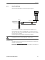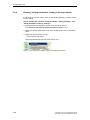
1
Operating Instructions 11/2012
SICLOCK TC100
Plant Central Clock
SICLOCK
s
s
Preface, Table of Contents
Safety instructions
SICLOCK® TC100
Plant Central Clock
Description
Hardware description
Operation planning
Operating Instructions
Mounting
Connection
Configuration Tool
Parameter assignment
Parameter assignment and operation
of the device
Parameter table
Service and maintenance
Messages
Technical data
Dimension drawing
Circuit diagrams
Spare parts / accessories
Annex
ESD guidelines
List of icons
Glossary, Index
11/2012
A2B00094941-02
Safety notices
This manual contains information that must be observed to ensure your personal safety and to prevent
property damage. The notices referring to your personal safety are highlighted in the manual by a safety
alert symbol, notices referring to property damage only, have no safety alert symbol. Depending on the
hazard level, warnings are displayed in descending order as follows:.
Danger
indicates that death or serious injury will result if proper precautions are not taken.
Warning
indicates that death or serious injury may result if proper precautions are not taken.
Caution
with a warning triangle indicates that minor personal injury can result if proper precautions are not taken.
Caution
without a warning triangle means that material damage can occur if the appropriate precautions are not
aken.
Notice
means an undesirable result or state can occur if the corresponding instruction is not followed.
In the event of a number of levels of danger prevailing simultaneously, the warning corresponding to the
highest level of danger is always used. A warning with a warning triangle indicating risk of physical injury
may also include a warning of the risk of damage to property.
Qualified personnel
The associated device/system may only be installed and used in conjunction with this documentation.
Only qualified personnel should be allowed to commission and operate the device/system. For the purpose of the safety information in this documentation, a “qualified person” is someone who is authorized to
energize, ground, and tag equipment, systems, and circuits in accordance with established safety
procedures.
Intended use
Please note the following:
Warning
This equipment is only allowed to be used for the applications described in the catalog and in the technical
description, and only in conjunction with non-Siemens equipment and components recommended by
Siemens. Correct transport, storage, installation and assembly, as well as careful operation and maintenance,
are required to ensure that the product operates safely and without faults.
Registered Trademarks
All designations with the trademark symbol ® are registered trademarks of Siemens AG. Other designations in this documentation may be trademarks whose use by third parties for their own purposes can violate the rights of the owner.
Disclaimer of liability
We have checked that the contents of this publication agree with the hardware and software described
here. Nevertheless, we cannot assume responsibility for any deviations that may arise. The information
given in this publication is reviewed at regular intervals and any corrections that might be necessary are
made in the subsequent editions.
Siemens AG
I IA CE EDM
Frauenauracher Strasse 98
D-91056 Erlangen
Germany
© Siemens AG 2010
Technical data subject to change.
Preface
This document contains the information required for operating and assigning
parameters to the SICLOCK TC100 central plant clock.
Area of application
This manual is valid for the SICLOCK® TC100 product with firmware version V1.0
and processor version V1.0 in conjunction with the SICLOCK TC100
Configuration Tool version 1.0 or higher.
Recycling and disposal
Die The SICLOCK TC100 is low in contaminants and can therefore be recycled.
For ecologically compatible recycling and disposal of your old device, contact a
certificated disposal service for electronic scrap.
Technical Assistance
If you have any technical questions, please contact Technical Assistance:
Phone:
+49 (911) 895-59 00
Monday to Friday, 8 am – 5 pm CET
Fax:
+49 (911) 895-59 07
E-Mail:
[email protected]
The latest information on SICLOCK products, product support and FAQs can be
found on the Internet:
• http://www.siemens.de/siclock (German)
• http://www.siemens.com/siclock (international)
© Siemens AG 2010 All Rights Reserved
SICLOCK® TC100 Operating Instructions
Preface-3
Preface
Preface-4
© Siemens AG 2010 All Rights Reserved
SICLOCK® TC100 Operating Instructions
Table of Contents
Preface. . . . . . . . . . . . . . . . . . . . . . . . . . . . . . . . . . . . . . . . . . . . . . . . . . . . . . .
Preface-3
1
Safety instructions . . . . . . . . . . . . . . . . . . . . . . . . . . . . . . . . . . . . . . . . . . . . .
1-9
2
Description . . . . . . . . . . . . . . . . . . . . . . . . . . . . . . . . . . . . . . . . . . . . . . . . . . .
2-11
2.1
Layout of the SICLOCK TC100 hardware . . . . . . . . . . . . . . . . . . . .
2-12
2.2
External synchronization . . . . . . . . . . . . . . . . . . . . . . . . . . . . . . . . . .
2-13
2.3
2.3.1
Time receivers. . . . . . . . . . . . . . . . . . . . . . . . . . . . . . . . . . . . . . . . . .
Plant synchronization via Ethernet . . . . . . . . . . . . . . . . . . . . . . . . . .
2-14
2-14
2.4
Time management . . . . . . . . . . . . . . . . . . . . . . . . . . . . . . . . . . . . . .
2-15
2.5
Commissioning . . . . . . . . . . . . . . . . . . . . . . . . . . . . . . . . . . . . . . . . .
2-15
2.6
Redundancy . . . . . . . . . . . . . . . . . . . . . . . . . . . . . . . . . . . . . . . . . . .
2-16
Hardware description . . . . . . . . . . . . . . . . . . . . . . . . . . . . . . . . . . . . . . . . . . .
3-17
3.1
Exterior design . . . . . . . . . . . . . . . . . . . . . . . . . . . . . . . . . . . . . . . . .
3-17
3.2
Connection elements. . . . . . . . . . . . . . . . . . . . . . . . . . . . . . . . . . . . .
3-18
3.3
Operator controls and displays . . . . . . . . . . . . . . . . . . . . . . . . . . . . .
3-19
3.4
Scope of supply. . . . . . . . . . . . . . . . . . . . . . . . . . . . . . . . . . . . . . . . .
3-21
Operation planning. . . . . . . . . . . . . . . . . . . . . . . . . . . . . . . . . . . . . . . . . . . . .
4-23
4.1
Overview of operation planning. . . . . . . . . . . . . . . . . . . . . . . . . . . . .
4-23
4.2
Transport / storage conditions. . . . . . . . . . . . . . . . . . . . . . . . . . . . . .
4-25
4.3
Unpacking and checking the delivery . . . . . . . . . . . . . . . . . . . . . . . .
4-26
4.4
4.4.1
4.4.2
4.4.3
Mounting position and fastening . . . . . . . . . . . . . . . . . . . . . . . . . . . .
Installation guidelines . . . . . . . . . . . . . . . . . . . . . . . . . . . . . . . . . . . .
Permissible mounting position. . . . . . . . . . . . . . . . . . . . . . . . . . . . . .
Type of fixation . . . . . . . . . . . . . . . . . . . . . . . . . . . . . . . . . . . . . . . . .
4-27
4-27
4-28
4-28
Mounting . . . . . . . . . . . . . . . . . . . . . . . . . . . . . . . . . . . . . . . . . . . . . . . . . . . . .
5-29
5.1
Overview of mounting . . . . . . . . . . . . . . . . . . . . . . . . . . . . . . . . . . . .
5-29
Connection . . . . . . . . . . . . . . . . . . . . . . . . . . . . . . . . . . . . . . . . . . . . . . . . . . .
6-31
6.1
Overview of connection . . . . . . . . . . . . . . . . . . . . . . . . . . . . . . . . . . .
6-31
6.2
Connecting the power supply . . . . . . . . . . . . . . . . . . . . . . . . . . . . . .
6-32
3
4
5
6
© Siemens AG 2010 All Rights Reserved
SICLOCK® TC100 Operating Instructions
Contents-5
Table of Contents
7
8
9
10
6.3
6.3.1
6.3.2
6.3.3
6.3.4
Connecting external synchronization . . . . . . . . . . . . . . . . . . . . . . . .
SICLOCK GPS1000 . . . . . . . . . . . . . . . . . . . . . . . . . . . . . . . . . . . . .
SICLOCK DCFRS Industrial version . . . . . . . . . . . . . . . . . . . . . . . . .
SICLOCK GPSDEC . . . . . . . . . . . . . . . . . . . . . . . . . . . . . . . . . . . . .
Third-party systems. . . . . . . . . . . . . . . . . . . . . . . . . . . . . . . . . . . . . .
6-33
6-35
6-36
6-37
6-38
6.4
Connecting alarm and warning outputs. . . . . . . . . . . . . . . . . . . . . . .
6-39
Configuration Tool . . . . . . . . . . . . . . . . . . . . . . . . . . . . . . . . . . . . . . . . . . . . .
7-41
7.1
Menus . . . . . . . . . . . . . . . . . . . . . . . . . . . . . . . . . . . . . . . . . . . . . . . .
7-44
7.2
7.2.1
7.2.2
General functions . . . . . . . . . . . . . . . . . . . . . . . . . . . . . . . . . . . . . . .
Connect / disconnect online connection . . . . . . . . . . . . . . . . . . . . . .
Authorization . . . . . . . . . . . . . . . . . . . . . . . . . . . . . . . . . . . . . . . . . . .
7-46
7-47
7-48
7.3
7.3.1
7.3.2
7.3.3
7.3.4
Parameters . . . . . . . . . . . . . . . . . . . . . . . . . . . . . . . . . . . . . . . . . . . .
Sorting Parameter tables. . . . . . . . . . . . . . . . . . . . . . . . . . . . . . . . . .
Hiding / showing Parameter table entries . . . . . . . . . . . . . . . . . . . . .
Editing parameters . . . . . . . . . . . . . . . . . . . . . . . . . . . . . . . . . . . . . .
Reading / writing parameters, setting to factory defaults . . . . . . . . .
7-49
7-53
7-53
7-54
7-56
7.4
7.4.1
7.4.2
Archive . . . . . . . . . . . . . . . . . . . . . . . . . . . . . . . . . . . . . . . . . . . . . . .
Sorting the Archive table . . . . . . . . . . . . . . . . . . . . . . . . . . . . . . . . . .
Filters. . . . . . . . . . . . . . . . . . . . . . . . . . . . . . . . . . . . . . . . . . . . . . . . .
7-57
7-60
7-61
7.5
Troubleshooting. . . . . . . . . . . . . . . . . . . . . . . . . . . . . . . . . . . . . . . . .
7-62
Parameter assignment and operation of the device . . . . . . . . . . . . . . . . .
8-65
8.1
Status display . . . . . . . . . . . . . . . . . . . . . . . . . . . . . . . . . . . . . . . . . .
8-66
8.2
8.2.1
8.2.2
8.2.3
Operation and parameter assignment. . . . . . . . . . . . . . . . . . . . . . . .
One-button operation with the MODE button . . . . . . . . . . . . . . . . . .
Network settings on the device . . . . . . . . . . . . . . . . . . . . . . . . . . . . .
Readout versions . . . . . . . . . . . . . . . . . . . . . . . . . . . . . . . . . . . . . . .
8-68
8-68
8-70
8-71
Parameter assignment . . . . . . . . . . . . . . . . . . . . . . . . . . . . . . . . . . . . . . . . . .
9-73
9.1
9.1.1
9.1.2
9.1.3
Connecting external synchronization . . . . . . . . . . . . . . . . . . . . . . . .
Radio clocks via terminals. . . . . . . . . . . . . . . . . . . . . . . . . . . . . . . . .
Operation as NTP client . . . . . . . . . . . . . . . . . . . . . . . . . . . . . . . . . .
Redundancy . . . . . . . . . . . . . . . . . . . . . . . . . . . . . . . . . . . . . . . . . . .
9-74
9-74
9-75
9-75
9.2
9.2.1
9.2.2
Connecting time receivers. . . . . . . . . . . . . . . . . . . . . . . . . . . . . . . . .
NTP server service . . . . . . . . . . . . . . . . . . . . . . . . . . . . . . . . . . . . . .
SIMATIC mode . . . . . . . . . . . . . . . . . . . . . . . . . . . . . . . . . . . . . . . . .
9-76
9-76
9-77
9.3
9.3.1
9.3.2
9.3.3
9.3.4
9.3.5
9.3.6
General settings on the device . . . . . . . . . . . . . . . . . . . . . . . . . . . . .
Time management . . . . . . . . . . . . . . . . . . . . . . . . . . . . . . . . . . . . . .
Synchronization. . . . . . . . . . . . . . . . . . . . . . . . . . . . . . . . . . . . . . . . .
Display. . . . . . . . . . . . . . . . . . . . . . . . . . . . . . . . . . . . . . . . . . . . . . . .
System . . . . . . . . . . . . . . . . . . . . . . . . . . . . . . . . . . . . . . . . . . . . . . .
Temperature . . . . . . . . . . . . . . . . . . . . . . . . . . . . . . . . . . . . . . . . . . .
Battery . . . . . . . . . . . . . . . . . . . . . . . . . . . . . . . . . . . . . . . . . . . . . . . .
9-78
9-78
9-79
9-80
9-80
9-81
9-81
Parameter table. . . . . . . . . . . . . . . . . . . . . . . . . . . . . . . . . . . . . . . . . . . . . . . .
10-83
Contents-6
© Siemens AG 2010 All Rights Reserved
SICLOCK® TC100 Operating Instructions
Table of Contents
11
Service and maintenance. . . . . . . . . . . . . . . . . . . . . . . . . . . . . . . . . . . . . . . .
11-89
11.1
Battery . . . . . . . . . . . . . . . . . . . . . . . . . . . . . . . . . . . . . . . . . . . . . . . .
11-89
11.2
Restoring factory defaults . . . . . . . . . . . . . . . . . . . . . . . . . . . . . . . . .
11-89
11.3
Software update . . . . . . . . . . . . . . . . . . . . . . . . . . . . . . . . . . . . . . . .
11-90
12
Messages . . . . . . . . . . . . . . . . . . . . . . . . . . . . . . . . . . . . . . . . . . . . . . . . . . . .
12-91
13
Technical data. . . . . . . . . . . . . . . . . . . . . . . . . . . . . . . . . . . . . . . . . . . . . . . . .
13-95
14
Dimension drawing. . . . . . . . . . . . . . . . . . . . . . . . . . . . . . . . . . . . . . . . . . . . .
14-99
15
Circuit diagrams . . . . . . . . . . . . . . . . . . . . . . . . . . . . . . . . . . . . . . . . . . . . . . .
15-101
15.1
Terminal assignment . . . . . . . . . . . . . . . . . . . . . . . . . . . . . . . . . . . . .
15-101
16
Spare parts / accessories . . . . . . . . . . . . . . . . . . . . . . . . . . . . . . . . . . . . . . .
16-103
A
Annex. . . . . . . . . . . . . . . . . . . . . . . . . . . . . . . . . . . . . . . . . . . . . . . . . . . . . . . .
A-105
A.1
Directives and declarations . . . . . . . . . . . . . . . . . . . . . . . . . . . . . . . .
A-105
A.2
Certificates and approvals. . . . . . . . . . . . . . . . . . . . . . . . . . . . . . . . .
A-106
ESD guidelines . . . . . . . . . . . . . . . . . . . . . . . . . . . . . . . . . . . . . . . . . . . . . . . .
B-107
B.1
Electrostatic sensitive devices. . . . . . . . . . . . . . . . . . . . . . . . . . . . . .
B-107
B.2
Electrostatic charging of persons . . . . . . . . . . . . . . . . . . . . . . . . . . .
B-108
B.3
Fundamental measures to protect against static discharge . . . . . . .
B-109
C
List of icons. . . . . . . . . . . . . . . . . . . . . . . . . . . . . . . . . . . . . . . . . . . . . . . . . . .
C-111
D
Glossary . . . . . . . . . . . . . . . . . . . . . . . . . . . . . . . . . . . . . . . . . . . . . . . . . . . . .
D-113
Index . . . . . . . . . . . . . . . . . . . . . . . . . . . . . . . . . . . . . . . . . . . . . . . . . . . . . . . .
Index-119
B
© Siemens AG 2010 All Rights Reserved
SICLOCK® TC100 Operating Instructions
Contents-7
Table of Contents
Contents-8
© Siemens AG 2010 All Rights Reserved
SICLOCK® TC100 Operating Instructions
Safety instructions
1
Caution
Please observe the safety instructions on the back of the cover sheet of this documentation. You should not expand your device unless you have read the relevant
safety instructions.
If you have questions about the validity of the installation in the planned environment, please contact your service representative.
Repairs
Only authorized personnel are permitted to repair the device.
Warning
Unauthorized opening and improper repairs can cause considerable damage to
property or danger for the user.
System expansions
Only install system expansion devices designed for this device. The installation
of other expansions can damage the system and violate the radio-interference
suppression regulations.
Contact your technical support team or where you purchased your PC to find out
which system expansion devices may safely be installed.
Caution
If you install or exchange system expansions and damage your device, the warranty becomes void.
© Siemens AG 2010 All Rights Reserved
SICLOCK® TC100 Operating Instructions
1-9
Sicherheitshinweise
Safety information
Siemens offers IT security mechanisms for its automation and drive product portfolio in order to support the safe operation of the plant/machine. Our products are
also continuously developed further with regard to IT security. We therefore
recommend that you keep yourself informed about updates and upgrades for our
products and always use the latest version of each product. For information on
this topic, refer to: Industry Online Support (http://www.siemens.com/automation/csi_de_WW). You can register for a product-specific newsletter here.
For the safe operation of a plant/machine, however, it is also necessary to integrate the automation components into an overall IT security concept for the entire
plant/machine which corresponds to state-of-the-art IT technology. You can find
information on this at: Industrial Security (http://www.siemens.com/industrialsecurity).
Products used from other manufacturers should also be taken into account here.
Network security
In order to protect the entire plant from attacks on network security, corresponding measures must be taken.
Caution
Failures or damage to your overall system
Unauthorized persons can gain entry into your network via the Ethernet ports and
make changes to the SICLOCK TC100 parameterization. This can result in the
time being adjusted. Individual or even all clients to be synchronized can be removed from the synchronization cycle. This has the potential to cause failures or
damage throughout the plant.
Please adhere to the following safety measures:
− Ensure that your network is protected against unauthorized access by installing a firewall at all Ethernet ports.
− Change the default password immediately after commissioning.
− Limit the number of people to whom this password is known to the absolute
minimum.
− Change the password regularly.
1-10
© Siemens AG 2010 All Rights Reserved
SICLOCK® TC100 Operating Instructions
Safety Information
Battery
This device is fitted with a Lithium battery. Batteries may only be replaced by
qualified personnel. See Battery (Chapter 11.1).
Caution
There is the risk of an explosion if the battery is not replaced as directed. Replace
only with the same type or with an equivalent type recommended by the manufacturer. Dispose of used batteries in accordance with local regulations.
Warning
Risk of explosion and release of harmful substances!
For this reason, do not throw lithium batteries into open fires, do not solder on the
cell body, do not open, do not short circuit, do not reverse polarity, do not heat
above 100°C, dispose of correctly, and protect against direct sunlight, dampness
and dew.
EGB directives
Modules containing electrostatic sensitive devices (ESDs) can be identified by the
following label:
Strictly follow the guidelines mentioned below when handling modules which are sensitive
to ESD:
•
Before working with modules with ESDs, you must discharge all your personal static
(e.g. by touching a grounded object).
• All devices and tools must be free of static charge.
• Always pull the mains connector before you install or remove modules which
are sensitive to ESD.
• Handle modules fitted with ESDs by their edges only.
• Do not touch any pins.
© Siemens AG 2010 All Rights Reserved
SICLOCK® TC100
1-11
Safety Information
1-12
© Siemens AG 2010 All Rights Reserved
SICLOCK® TC100 Operating Instructions
Description
2
Modern automation systems are made up of a multitude of computers, controllers
and systems, that exchange data with one another. In order to operate such systems in real time, it is absolutely essential to synchronize the clock times of all the
components involved. This particularly applies to error tracing if event messages
are time stamped, and cause and effect have to be identified by a reliable chronological order.
As a central plant clock, SICLOCK TC100 supplies the various plant components
with a precise, reliable clock time, which is usually obtained from one or more
external synchronizations with official or statutory times of day, usually GPS or
DCF77 radio clocks.
SICLOCK TC100 distributes the time solely via Ethernet.
Note
Use one single device as the central clock for the whole plant, which supplies the
clock time to all the other devices.
Exception: Redundant operation of the central plant clock
© Siemens AG 2010 All Rights Reserved
SICLOCK® TC100 Operating Instructions
2-1
Description
2.1
Layout of the SICLOCK TC100 hardware
The following diagram shows an application example of a SICLOCK TC100, with
a SICLOCK GPS1000 as the radio clock and an NTP server as an additional
external synchronization.
Figure 2-1 Application Example
2-1
© Siemens AG 2010 All Rights Reserved
SICLOCK® TC100 Operating Instructions
Description
2.2
External synchronization
SICLOCK TC100 can be externally synchronized to the applicable, statutory national time or GMT in order to automate or minimize manual interventions, such as
daylight saving time changes and leap seconds.
External synchronizations can be GPS or DCF77 radio clocks, servers (e.g. the
time signal from an NTP server), SICLOCK TC400 devices, SICLOCK TC100
devices or other signal sources. They are connected to the RADIO CLOCK of the
device.
The Ethernet port supports NTP servers as external synchronizations.
Possible RADIO CLOCKS are:
• SICLOCK GPS1000
• SICLOCK GPSDEC
(SICLOCK GPSDEC has been discontinued, please use SICLOCK GPS1000)
ವ
SICLOCK DCFRS
Third-party products can be connected passively via TTY. The following protocols
are supported:
• Demodulated DCF77
• Serial:
− Meinberg format (time-zone dependent)
− Meinberg format (time-zone independent)
− NMEA (0183/ZDA)
Get more information
Connecting external synchronization (Chapter 9.1)
© Siemens AG 2010 All Rights Reserved
SICLOCK® TC100 Operating Instructions
2-1
Description
2.3
Time receivers
The time receivers in the plant are connected solely via Ethernet.
2.3.1
Plant synchronization via Ethernet
Physical access
An Ethernet port with the following specification is provided to enable physical
access to the network:
• 100Base-TX via RJ-45 socket
Protocols
The following protocols are implemented:
• NTP server according to RFC2030
− Any/unicast mode
− Any/unicast mode with local time
− Multicast mode
− Multicast mode with local time
•
Time synchronization in the SIMATIC procedure
− PCS7-compatible mode
− S5-compatible mode
Thetime message frames can be transmitted to each Ethernet port individually either every second or every 10 seconds.
2-1
© Siemens AG 2010 All Rights Reserved
SICLOCK® TC100 Operating Instructions
Description
2.4
Time management
The SICLOCK TC100 has a range of functions for generating the valid plant time
from the external synchronization. This includes the option of setting times zones
and the parameterizable generation of daylight saving.
Time security through protected synchronization
If a discontinuity of longer than five seconds occurs in the external synchronization, the protected synchronization is activated, and the synchronization is not
executed for safety reasons.
Time security through microstep mode
A time difference between the external synchronization and the device, such as
can occur as the result of a brief loss of loss of radio contact or switching to a substitute synchronization, is run down automatically in microstep mode that is imperceptible to the operation of the plant. No time jump occurs.
More detailed information and the options for parameter assignment for protected
synchronization and microstep mode are described in the chapter
Synchronization (Chapter 9.3.2).
Note
Parameterize the plant time at one single point within the synchronization hierarchy, ideally on the central plant clock.
2.5
Commissioning
Commissioning can be subdivided into the following steps:
1. Mounting (Chapter 5)
2. Connection (Chapter 6)
3. Assignment of an IP address to the device
Parameter assignment and operation of the device (Chapter 8)
4. Parameter assignment (Chapter 9)
With few exceptions, the settings are made with the Configuration Tool, see
Configuration Tool (Chapter 7).
© Siemens AG 2010 All Rights Reserved
SICLOCK® TC100 Operating Instructions
2-1
Description
2.6
Redundancy
Redundant external synchronization
Up to four time servers can be run on the SICLOCK TC100 for external synchronization via NTP. However, they must all be in the same IP network.
Radio clocks cannot be connected redundantly to a SICLOCK TC100.
The order of priority among the external synchronizations (radio clock or NTP server), and thus the redundancy behavior, can be set with parameters, see
Redundancy (Chapter 9.1.3).
Redundant SICLOCK TC100 central plant clocks
A number of SICLOCK TC100s can be run as redundant time servers in a single
network.
You will find more detailed information in the chapters Configuration Tool
(Chapter 7) and Parameter table (Chapter 10).
You can find more information on redundancy in
„Application Note 0108“ on http://www.siemens.com/siclock under "FAQ".
2-1
© Siemens AG 2010 All Rights Reserved
SICLOCK® TC100 Operating Instructions
3
Hardware description
The layout of the hardware, together with the connectors, operator controls and
displays are described in this chapter.
3.1
Exterior design
The display and operator controls together with the connectors on the
SICLOCK TC100 are shown in the following figures.
Figure 3-1 Perspective view of the SICLOCK TC100 showing the front panel and ventilation grille
(1)
Panel with operator and display controls
(2)
Ventilation grille
© Siemens AG 2010 All Rights Reserved
SICLOCK® TC100 Operating Instructions
3-1
Hardware description
3.2
Connection elements
The following figure shows the connectors on the SICLOCK TC100.
Figure 3-2 SICLOCK TC100 - layout of connectors
(1)
(2)
Terminal X1 - 24V supply voltage
Terminal X2 - connecting terminal for radio clocks, outputs and alarm
See also Terminal assignment (Chapter 15.1).
(3)
3-
Ethernet port
© Siemens AG 2010 All Rights Reserved
SICLOCK® TC100 Operating Instructions
Hardware description
3.3
Operator controls and displays
The display and LEDs on the front panel show the current operating state. The
keypad can be used for the basic operation of the device. A Web-based Configuration Tool is available for more extensive configuration options, see
Configuration Tool (Chapter 7).
Figure 3-3 SICLOCK TC100 front view
© Siemens AG 2010 All Rights Reserved
SICLOCK® TC100 Operating Instructions
3-
Hardware description
Table 3-1
Meanings of the displays and operator controls
Name
Color (LED)
Meaning
Displays
POWER
Green
Operational readiness
SYNC
Green
SICLOCK TC100 is externally synchronized.
FAULT
Red
Alarm
The associated message text is shown in the display.
Flashing red Warning
The associated message text is shown in the display.
LINK
Green
The physical connection has been made, transmission and
reception are possible.
ACTIVE
Green
Display of the data traffic for the particular port
RADIO CLOCK
Yellow
Incoming signal from the radio clock
Display
Display of the time, date and synchronization, or message
text in the case of an error
Operator controls
MODE
Call and edit the basic parameter list
Acknowledge messages
For more detailed information see Parameter assignment and operation of the device
(Chapter 8).
3-2
© Siemens AG 2010 All Rights Reserved
SICLOCK® TC100 Operating Instructions
Hardware description
3.4
Scope of supply
Table 3-2
Scope of supply of the individual versions of the device
2XV9450-2AR22
SICLOCK TC100 single device with terminal strips connected to X1 and X2
2XV9450-2AR50 (SICLOCK TC100 GPS1000 package)
SICLOCK TC100 single device with terminal strips connected to X1 and X2
SICLOCK GPS1000 radio clock with mounting frame and lightning protection
2XV9450-2AR26 (SICLOCK TC100 DCF77 package)
SICLOCK TC100 single device with terminal strips connected to X1 and X2
SICLOCK DCFRS industrial version of the radio clock, complete with mounting frame
© Siemens AG 2010 All Rights Reserved
SICLOCK® TC100 Operating Instructions
3-2
Hardware description
3-2
© Siemens AG 2010 All Rights Reserved
SICLOCK® TC100 Operating Instructions
Operation planning
4.1
4
Overview of operation planning
SICLOCK TC100 is designed for stationary use in weather-proof locations in an
industrial environment.
The operating conditions surpass the requirements of DIN IEC 60721-3-3.
• Class 3M3 (mechanical requirements)
• Class 3K3 (climatic requirements)
General notes on operation
Caution
The device is approved for operation in closed rooms only. The guarantee is void
if this stipulation is ignored.
Condensation
When transporting the device at low temperatures, ensure that no moisture gets
on or into the device. This also applies if the device is subjected to extreme changes in temperature.
Commissioning
Allow the device to slowly adjust to room temperature before commissioning the
device. However, do not expose the device to direct heat radiation. In the event
of greater temperature differences, harmful condensation can be avoided by leaving the device in its transport packaging.
If condensation develops, wait 12 hours before you switch on the device (for a
temperature difference of 20°C). For greater temperature differences, the waiting
time is correspondingly longer.
Avoid extreme ambient conditions. Protect your device against dust, moisture and
heat. Refer to Technical data (Chapter 13).
Do not place the device in direct sunlight.
© Siemens AG 2010 All Rights Reserved
SICLOCK® TC100 Operating Instructions
4-2
Operation planning
Use in residential areas, and operation in the public network
If you use the SICLOCK TC100 in residential areas or in the public network, you
must ensure that it complies with the limit value class B according to EN 55022
with regard to the emission of radio interference.
Note
This is a Class A system. The equipment may cause RF interference in residential
areas or the public network. In this case, the operating company may be required
to take appropriate measures.
The following measures are recommended to ensure the interference complies
with limit value class B:
• Install the SICLOCK TC100 in grounded control cabinets / control boxes
• Use filters in the supply lines
Usage with additional measures
SICLOCK TC100 must not be used in the following exemplary cases without
additional measures:
• At locations with a high level of ionizing radiation
• In aggressive environments caused, for example, by
− The development of dust
− Corrosive vapors or gases
− Strong electric or magnetic fields
− Damp and wet rooms
− Severe oscillations, shocks, vibrations
− High levels of radiant heat
• In systems that require special monitoring, such as.
− Elevators
− Electrical plants in potentially hazardous areas
One additional measure could be to install the SICLOCK TC100 in a cabinet or
housing.
4-2
© Siemens AG 2010 All Rights Reserved
SICLOCK® TC100 Operating Instructions
Operation planning
4.2
Transport / storage conditions
Despite the device's rugged design, its internal components are sensitive to
severe vibrations and shock. You must therefore protect the device from severe
mechanical stresses.
You should always use the original packaging for shipping and transporting the
device.
Unpack the device at its installation location.
Do not transport the device when it is mounted.
Follow the instructions for temporary storage under Battery (Chapter 11.1) in
Service and maintenance.
The following information applies to modules transported or stored in their original
packaging.
The ambient conditions for transport comply with IEC 60721-3-2, class 2K4.
The mechanical environmental conditions for transport comply with
IEC 60721-3-2, class 2M2.
Caution
Risk of damage to the device!
If the device is transported in extreme weather conditions with large fluctuations
in temperature, care must be taken to ensure that no moisture forms on or in the
device (condensation).
If you notice any condensation, wait around 12 hours before switching on the
device.
Notice
Adhere to these stipulations each time the device is transported, otherwise the
guarantee is void.
Table 4-1
Shipping and storage conditions
Type of condition
Permissible range
Free fall (in transport packaging)
<= 1 m
Temperature
-40 °C to +70 °C
Atmospheric pressure
From 1080 to 660 hPa (corresponds to an
altitude from -1000 to 3500m)
Maximum rate of temperature
change
20 °C/h
Relative humidity
10 to 95 % (at 25°C without condensation)
© Siemens AG 2010 All Rights Reserved
SICLOCK® TC100 Operating Instructions
4-2
Operation planning
4.3
Unpacking and checking the delivery
The device is completely assembled, tested and packed in the factory, and has
no internal transport locks.
If there are large temperature differences between the means of transport and the
unpacking site, we recommend leaving the device in its transport packaging to
avoid harmful condensation.
Procedure
• Please check the packaging material for transport damage upon delivery.
• If any transport damage is present at the time of delivery, lodge a complaint
with the responsible shipping company. Have the shipper confirm the transport damage immediately.
• Unpack the device.
• Keep the packaging material in case you have to transport the device again.
Notice
The packaging protects the device during transport and storage. Transport the
device only in its original packaging!
• Please keep the accompanying documentation in a safe place. You will need
the documentation when you start up the device for the first time.
• Check the package contents for completeness and any visible transport
damage. Check for completeness using the enclosed "Contents of Delivery"
list.
• Notify the responsible delivery service immediately if the packages contents
are incomplete or damaged.
Warning
Ensure that a damaged device is neither inadvertently installed nor brought into
operation.
4-2
© Siemens AG 2010 All Rights Reserved
SICLOCK® TC100 Operating Instructions
Operation planning
4.4
Mounting position and fastening
4.4.1
Installation guidelines
Before installing the device, read the following general notes relating to
installation.
Warning
Danger, high voltage!
Disconnect the power supply from the control cabinet before opening it. Ensure
that the power to the control cabinet cannot be switched on accidentally.
• Locate the device / display in an ergonomically advantageous position for the
user. Choose a suitable installation height.
• Position the device / display so that it is not exposed to direct sunlight or other
strong sources of light.
• Ensure that there is adequate free space in the control cabinet for air circulation and heat transport. Maintain a clearance of 100mm above and below the
device. Connection cables increase these clearances correspondingly.
• Install the device in a position that does not block the air vents in the housing.
• Also provide enough free space to be able to remove the device.
• Fit struts in the control cabinet to stabilize the mounting cut-out. Install struts
where necessary.
• Install the device in such a way that it cannot pose any danger by, for example,
falling out.
• During assembly, please comply with the approved installation positions.
See Dimension drawing (Chapter 14).
© Siemens AG 2010 All Rights Reserved
SICLOCK® TC100 Operating Instructions
4-2
Operation planning
4.4.2
Permissible mounting position
Only a horizontal mounting position is permitted, that is the display is read from a
horizontal viewing direction. The ventilation is inadequate in all other mounting
positions.
Figure 4-1 Horizontal mounting position
4.4.3
Type of fixation
The housing can be fixated by snap-on mounting to a standard mounting rail or
to a SIMATIC S5 DIN rail.
See Overview of mounting (Chapter 5.1).
4-
© Siemens AG 2010 All Rights Reserved
SICLOCK® TC100 Operating Instructions
Mounting
5.1
5
Overview of mounting
Figure 5-1 SICLOCK TC100 - view of mounting
SICLOCK TC100 must be mounted in an easily accessible position in the control
cabinet.
The housing can be fixated by snap-on mounting to a standard mounting rail
(EN 50022-35) or to a SIMATIC S5 DIN rail (6ES5 710-8maxx).
A clearance of 100mm must be maintained above the device so that it can be
hooked in and out, and to facilitate unimpeded heat dissipation.
A clearance of at least 100mm must be maintained under the device for the process signal plug.
We recommend mounting a suitable cable channel below this clearance.
Note
Ensure that the snap-on mounting is locked correctly.
See also Dimension drawing (Chapter 14).
© Siemens AG 2010 All Rights Reserved
SICLOCK® TC100 Operating Instructions
5-
Mounting
5-3
© Siemens AG 2010 All Rights Reserved
SICLOCK® TC100 Operating Instructions
Connection
6.1
6
Overview of connection
Notice
Only connect peripheral devices suitable for an industrial environment.
Caution
Strictly adhere to the specifications for peripheral equipment.
Ensure that the installation complies with the following conditions:
• The device may only be connected to 24 VDC power supply systems which
meet the requirements of a safe extra-low voltage with protective separation
according to SELV. The conductor cross-section selected must be large
enough so that if there is a short circuit in the SICLOCK TC100 no damage
can be caused by an overheated cable. For the conductor cross-section, see
Connecting the power supply (Chapter 6.2).
• Avoid extreme ambient conditions as far as possible.
• Protect the device against dust, moisture, heat and severe vibrations.
• Do not place the device in direct sunlight.
• Install the device in such a way that it cannot pose any danger, for example by
falling down.
• Do not cover the ventilation slots
• Permissible mounting position (Chapter 4.4.2).
© Siemens AG 2010 All Rights Reserved
SICLOCK® TC100 Operating Instructions
6-3
Connection
6.2
Connecting the power supply
The power supply is connected to terminal strip X1, and muss pass through a
slow-blow 1A fuse. The device does not have a power switch.
Figure 6-1 Connecting the power supply
Note before connecting the device
Warning
The device may only be connected to 24 VDC power supply systems which meet
the requirements of a safe extra-low voltage with protective separation (SELV); a
protective conductor must also be connected. The conductors must be able to
withstand the short-circuit current of the 24 VDC power supply, so that a short circuit will not damage the cable. Only cables with a cross-section between a minimum of 0.25 mm2 (AWG23) and a maximum of 2.50 mm2 (AWG13) may be
connected.
Notice
The 24 VDC power supply must match the input specification of the device
Technical data (Chapter 13).
Caution
Ensure that the functional grounding is connected correctly.
It is essential to ensure the correct polarity with direct current.
Functional check
After switching on, the POWER LED must light up green.
6-3
© Siemens AG 2010 All Rights Reserved
SICLOCK® TC100 Operating Instructions
Connection
6.3
Connecting external synchronization
The signal from the connected radio clock is automatically detected, and displayed in the parameter /Inputs/Input 1/Status (0.20.02).
Figure 6-2 Circuit diagrams for a passive and an active radio clock
Table 6-1
Terminal assignment of radio clock inputs
Terminal
Description
X2-1
RADIO CLOCK GND
X2-2
RADIO CLOCK 1A
X2-3
RADIO CLOCK 1B
© Siemens AG 2010 All Rights Reserved
SICLOCK® TC100 Operating Instructions
6-3
Connection
Functional check
The incoming signal of the radio clock is indicated on the front panel by the
"RADIO CLOCK" LED.
The status of the radio clock is displayed in the parameter
/Inputs/Input 1/Status (0.20.02).
Possible states:
• GPS (SICLOCK GPS1000 and SICLOCK GPSDEC)
• GPS (disturbed)
The signal reception is temporarily disturbed.
• DCF77 (SICLOCK DCFRS and SICLOCK GPSDEC)
• DCF77 (disturbed)
The signal reception is temporarily disturbed.
• Serial
− Meinberg
Meinberg format being received
− NMEA
NMEA format being received
− Telegram (disturbed)
Error detected in telegram or loss of telegram
• No signal
The connection of individual sources of external synchronization is described in
the following.
6-3
© Siemens AG 2010 All Rights Reserved
SICLOCK® TC100 Operating Instructions
Connection
6.3.1
SICLOCK GPS1000
The GPS receiver GPS1000 is connected according to Figure 6-3.
;
5$',2&/2&.*1'
5$',2&/2&.$
5$',2&/2&.%
/LJKWQLQJSURWHFWLRQ
PD[P
Figure 6-3 Connection of the radio clock SICLOCK GPS1000 to RADIO CLOCK 1
We recommend using a two-wire, shielded cable, e.g. LiYCY 2x1 mm² as the
radio clock cable. One end of the cable shielding must be connected to a suitable
point at the place of installation.
No further assignment of parameters to the GPS1000 is required.
Warning
Provide lightning protection for the GPS aerial in outdoor areas.
Functional check
The "RADIO CLOCK" LED on the front panel must flash at about 1Hz when the
GPS1000 is received correctly.
The parameter /Inputs/Input 1/Status (0.20.02) must change to "GPS" after about
three minutes reception.
© Siemens AG 2010 All Rights Reserved
SICLOCK® TC100 Operating Instructions
6-3
Connection
6.3.2
SICLOCK DCFRS Industrial version
The industrial version of the SICLOCK DCFRS radio clock included in the DCF77
package is connected as shown in Figure 6-4. In this case the polarity is irrelevant.
PD[P
;
5$',2&/2&.*1'
5$',2&/2&.$
5$',2&/2&.%
Figure 6-4 Connection of the radio clock SICLOCK DCFRS industrial version to
RADIO CLOCK 1
Warning
When used outdoors, a lightning conductor must also be installed.
Note
One end of the shielding of the radio clock cable must be connected to a suitable
point at the place of installation.
Functional check
The "RADIO CLOCK" LED on the front panel must flash at about 1Hz when the
SICLOCK DCFRS is received correctly.
The parameter /Inputs/Input 1/Status (0.20.02) must change to "DCF77" after
about three minutes reception.
Note
If possible select a location for the aerial where there is no electromagnetic interference on the DCF77 carrier frequency, because this is crucial for the quality of
reception. Do not mount the aerial anywhere near electric drives, neon tubes,
monitors or other emitters of interference.
6-3
© Siemens AG 2010 All Rights Reserved
SICLOCK® TC100 Operating Instructions
Connection
6.3.3
SICLOCK GPSDEC
(SICLOCK GPSDEC has been discontinued, please use SICLOCK GPS1000)
A SICLOCK GPSDEC decoder is connected as shown in Figure 6-5.
'&)77<
;
5$',2&/2&.*1'
5$',2&/2&.$
5$',2&/2&.%
PD[P
Figure 6-5 Connection of the radio clock SICLOCK GPSDEC to RADIO CLOCK 1
Caution
A SICLOCK GPSDEC may only be operated as an active radio clock.
Operation as a passive radio clock leads to the destruction of the
SICLOCK GPSDEC.
Table 6-2
Recommended assignment of parameters to the GPSDEC decoder for
synchronizing a SICLOCK TC100
Parameter
Setting
Time difference from GMT
00:00
Daylight saving time change
„none“
X1.5-8 (DCF77TTY)
„DCF without ZZB“
Functional check
The "RADIO CLOCK" LED on the front panel must flash at about 1Hz when the
GPSDEC is received correctly.
The parameter /Inputs/Input 1/Status (0.20.02) must change to "GPS" or "DCF77"
after about three minutes reception.
© Siemens AG 2010 All Rights Reserved
SICLOCK® TC100 Operating Instructions
6-3
Connection
6.3.4
Third-party systems
Third-party systems can also be used for external synchronization of the
SICLOCK TC100 if the following conditions are fulfilled.
Prerequisites
• Active radio clock signal with 20mA rated current
• Supported signals:
− Demodulated DCF77
− Serial:
Meinberg format (time-zone dependent),
Meinberg format (time-zone independent),
NMEA (0183/ZDA)
Functional check
The parameter /Inputs/Input 1/Status (0.20.02) must change to "Meinberg",
"NMEA" or "DCF77" after about three minutes reception.
6-
© Siemens AG 2010 All Rights Reserved
SICLOCK® TC100 Operating Instructions
Connection
6.4
Connecting alarm and warning outputs
During operation, the SICLOCK TC100 automatically carries out a range of function tests. If an error occurs, the device generates corresponding messages on
the display. A distinction is made between alarms and warnings.
There is an alarm output and a warning output for external monitoring on terminal
X2.
;
;
;
Figure 6-6 Alarm output X2-7 and warning output X2-8
Table 6-3
Parameters affecting the alarm behavior
/Synchronization/Extended/Monitoring/Monitor Synchronization Status (0.09.14)
/Network Settings/Ethernet 1/Extended Settings Adapter 1/Monitor Link Status (0.05.09)
/NTP Client/Monitoring/Monitor Server (0.18.04)
/Environment/Extended/Temperature/Monitoring (0.24.01)
Example:
Set the alarm output if there is no external synchronization.
Use the Configuration Tool to set the parameter entry /Synchronisation/Exended/Monitoring/Monitor Synchronization Status (0.09.14) = "Alarm" to activate
monitoring / alarm output in case of error.
Note
The contacts are designed as wire-break-proof, normally closed contacts. If there
is an alarm or warning, the corresponding contact opens.
© Siemens AG 2010 All Rights Reserved
SICLOCK® TC100 Operating Instructions
6-
Connection
6-4
© Siemens AG 2010 All Rights Reserved
SICLOCK® TC100 Operating Instructions
Configuration Tool
7
The SICLOCK TC100 Configuration Tool is available to make it easier to assign
parameters and configure the SICLOCK TC100. The tool can be called from an
Internet browser as a Web interface.
With the Configuration Tool you can, among other things, view and change parameters online and offline, view archives, search them with specific filter criteria,
and load, backup and change the parameter assignments of the
SICLOCK TC100 device.
Figure 7-1 SICLOCK TC100 Configuration Tool
(1) Toolbar of the Configuration Tool
(2) Working area of the Configuration Tool
You can make settings and assign parameters in the Parameter tab, and check
and search for events in the Archive tab.
©Siemens AG 2010 All Rights Reserved
SICLOCK® TC100 Operating Instructions
7-4
Configuration Tool
Preconditions
PC
• Minimum screen resolution of 1280x1024
• Java Runtime of at least V1.4.0 or higher
• Web browser, e.g. Microsoft Internet Explorer
• Connection with the Ethernet port on the device
SICLOCK TC100
• Assignment of an IP address to the device
A valid IP address must be assigned to the Ethernet port of the device. The
device is supplied with the address 192.168.1.10 and subnet mask
255.255.255.0. See also Network settings on the device (Chapter 8.2.2).
The PC and device must be in the same subnetwork.
Parameters, entries and lists
A parameter is defined as a group of related values. Each of these values is termed an entry in its parameter.
Similar parameters can form a list. Such lists are indicated by [ ].
Notice
Entries can be individually edited, but not individually read or written. A parameter
is always read or written with all its entries. If it is a list, the complete list is read or
written.
Parameters are identified by their unique parameter number. The parameter
number always has three parts, e.g. 0.05.12.
Example: parameter /Display/Display (0.10.01) with the entries "Language" and
"Time":
Figure 7-2 Parameter display
7-4
© Siemens AG 2010 All Rights Reserved
SICLOCK® TC100 Operating Instructions
Configuration Tool
Working with the Configuration Tool
How to start the Configuration Tool:
1. Open the Web browser
2. Enter the address of the device port, e.g. 192.168.1.10
3. If necessary, confirm the installation and execution of the applet with "Yes"
and/or "Always".
−> The Configuration Tool is started and displayed in the browser.
Note
Take note of the information in your browser concerning restrictions as a result of
high security settings.
How to assign parameters to the SICLOCK TC100 with the Configuration
Tool:
1. Connect the Configuration Tool to the SICLOCK TC100 with the button
2. In the case of a new assignment of parameters to the device, load the parameters into the Configuration Tool with the
button, or open an existing
parameter file (*.u600) with the button
.
3. Assign parameters to the SICLOCK TC100 according to your hardware configuration and requirements.
In online mode, changes become immediately effective in the device.
4. Back up the configuration as a parameter file (*.u600) on your PC with the
button.
Note
In order to be able to fall back on the last version of the SICLOCK TC100 parameter assignment, we recommend backing up the current parameter assignment
of SICLOCK TC100 as a *.u600 file before you make any changes.
© Siemens AG 2010 All Rights Reserved
SICLOCK® TC100 Operating Instructions
7-4
Configuration Tool
7.1
Menus
Table 7-1
Menus in the Configuration Tool
Menu / function
Meaning / note
File
Open
Loads a parameter assignment/an archive from the local file system
See also General functions (Chapter 7.2).
Save
Saves a parameter assignment/an archive to a local file system
See also General functions General functions (Chapter 7.2).
End
Link
Exits application
See also Connect / disconnect online connection (Chapter 7.2.1).
Connect
Connects to a device
Disconnect
Disconnects from a device
Data transfer
See also Connect / disconnect online connection (Chapter 7.2.1).
(online connection required)
Download parameters
from device
Loads all parameters from a connected device onto the PC
See also Parameters (Chapter 7.3).
Update the parameters Updates all the parameters so far loaded on the PC with the values
from the device
from the connected device
See also Parameters (Chapter 7.3).
Upload parameters to
the device
Writes all parameter from the PC into the connected device
Download archive
Loads the complete archive from the connected device onto the PC
See also Parameters (Chapter 7.3).
See also Archive (Chapter 7.4).
Update archive
Requests/updates the archive of a connected device
See also Archive (Chapter 7.4).
View
Parameters
Changes to parameter view
See also Parameters (Chapter 7.3).
Archive/events
Changes to the archive/events view
See also Archive (Chapter 7.4).
Language
Selects one of the languages available for the user interface
Depending on the version, more languages could be offered for
selection:
• English (standard language)
• German
The language/naming of parameters and archives are supplied by the
device. Provided that the device recognizes the language set in the
Configuration Tool, the parameters and archives will be displayed in this
language. If the device does not recognize the language, the display will
be in the standard language.
7-4
© Siemens AG 2010 All Rights Reserved
SICLOCK® TC100 Operating Instructions
Configuration Tool
Table 7-1
Menus in the Configuration Tool
Menu / function
Meaning / note
?
Help…
Calls Help system
Version…
Displays version information for the Configuration Tool
© Siemens AG 2010 All Rights Reserved
SICLOCK® TC100 Operating Instructions
7-4
Configuration Tool
7.2
General functions
The toolbar of the Configuration Tool provides general functions for the parameters and the archive. You can also acknowledge events, and authorize yourself in
the Configuration Tool.
Table 7-2
Possible operations and displays in the toolbar of the Configuration Tool
Field / button
Meaning / instruction
Loads a parameter assignment/an archive from the local file system
Open
The file must be in the U600 format (*.u600). The parameter assignment
and the archive are loaded from the file when it is opened.
Notice
The currently loaded data (parameter assignment and archive) are
overwritten.
Saves a parameter assignment/an archive to a local file system
Save
The data (parameter assignment and archive) are saved in U600 format
(*.u600).
IP address of the SICLOCK TC100
Enter the IP address of the device here.
IP address
Connects to a device
The connection is established to the device with the given IP address.
Connect to device
Disconnects from device
The connection is terminated.
Die aufgebaute Verbindung wird getrennt.
Disconnect from device
See also Connect / disconnect online connection (Chapter 7.2.1).
Enter a password to enable a higher access level
Password supplied with device: "2222"
Authorization - password
See also Authorization (Chapter 7.2.2).
Executes authorization with the password entered
Authorize
Events currently pending in the device
Event
(online connection
required)
In online mode, the events pending in the device are shown (e.g.
warnings, alarms, etc.)
In offline mode, the display contains no information.
Acknowledges pending event
Confirm event
(online connection
required)
7-4
In online mode, an acknowledgment for the pending event is sent to the
device. Provided that it is acknowledgeable, the device deletes the event
from the display. Non-acknowledgeable events (persistent indications)
remain in the display.
© Siemens AG 2010 All Rights Reserved
SICLOCK® TC100 Operating Instructions
Configuration Tool
Table 7-2
Possible operations and displays in the toolbar of the Configuration Tool
Field / button
Meaning / instruction
Acknowledges all pending events
In online mode, an acknowledgment for all pending events is sent to the
device. An acknowledgment is made, even if the cause of the event is still
pending. This enables, e.g., persistent alarms to be deactivated.
Confirm all events
Rejects the pending event
The event display is deleted without interaction with the device.
Ignore event
7.2.1
Connect / disconnect online connection
How to establish an online connection to the SICLOCK TC100:
1. Enter the IP address of the device in the toolbar.:
2. Start establishing the connection by clicking the icon
address field.
next to the IP
−> The Configuration Tool changes into online mode:
How to terminate the online connection to the SICLOCK TC100:
1. Click
next to the IP address field.
−> The Configuration Tool changes into offline mode:
Note
The connection to the device is terminated after about two hours without operator
input.
© Siemens AG 2010 All Rights Reserved
SICLOCK® TC100 Operating Instructions
7-4
Configuration Tool
7.2.2
Authorization
There are authorization levels for each parameter, which allow or forbid read and
write accesses to the parameter. The operator interface initially starts with the
lowest authorization level, which mostly only allows read access to parameters.
You obtain more rights by inputting the corresponding password.
The user can change the password.
• Parameter /System/Authorization For Standard Protection (2.06.02)
Note
The combination "0000" is not permitted as a password. Setting the password to
"0000" disables access with this authorization level. Access is then only possible
using the service password. The service password can be requested from Technical Assistance by an authorized person.
The device is supplied with the password: "2222"
The current authorization level is indicated by the color of the password field.
Write protection - red entry field
In this authorization level, the user typically has only read access to standard
parameters.
Standard protection - green entry field
In this authorization level, the user typically also has read access to extended
parameters and write access to standard parameters.
Online mode
Authorization is executed directly on the device, i.e. the device assigns an appropriate authorization level.
Offline mode
You can authorize yourself for a higher authorization level with a password, provided that it is included in the loaded offline authorization parameters.
Note
In offline mode, it is not possible to authorize oneself with a password that is present in the device but is not included in the offline authorization parameters.
7-
© Siemens AG 2010 All Rights Reserved
SICLOCK® TC100 Operating Instructions
Configuration Tool
7.3
Parameters
You can set and transfer parameters to the SICLOCK TC100 in the Parameter
tab of the Configuration Tool in both offline and online modes.
Figure 7-3 SICLOCK TC100 Configuration Tool - Parameters
(1) Toolbar of the parameter tab
(2) Parameter tree
(3) Parameter table
(4) Parameter info
©Siemens AG 2010 All Rights Reserved
SICLOCK® TC100 Operating Instructions
7-
Configuration Tool
Table 7-3
Possible operations and displays in the Parameter tab
Field / button
Meaning / instruction
Outputs parameter assignment in a text file.
Print table in text file
The currently displayed parameter assignment is output in a text file. The
data can be further processed, e.g., with Excel.
Notice
Parameter assignments cannot be restored from these text files. In order to
restore a parameter assignment, it must have previously been saved in U600
format.
See open/save in General functions (Chapter 7.2).
Loads the parameters of the connected device
Download parameters
(online connection
required)
The parameters of the connected device, including its description data (e.g.
texts in all languages), are loaded. This can take several minutes. The
parameter assignment is also implicitly reloaded from the device.
Notice
The displayed parameter assignment data are overwritten. The archived data
are not accepted from the device, i.e. the displayed archived data are
retained.
See also Connect / disconnect online connection (Chapter 7.2.1).
Loads the parameters of the connected device without parameter description
Update parameters
(online connection
required)
The parameters of a connected device are loaded without the description
data. This can take several minutes.
Notice
The displayed parameter assignment data are overwritten. The archived data
are not accepted from the device, i.e. the displayed archived data are
retained.
See also Connect / disconnect online connection (Chapter 7.2.1).
Transfers the writable values of the loaded parameters to the connected
device
Upload parameters
The following values/parameters are not transferred into the device:
(online connection
required)
•
Values of write-protected parameters
•
Operationally critical parameters
•
Display parameters
• Command parameters
To transfer the parameter, an online connection must be established to the
device and the Confiiguration Tool correspondingly authorized. See also
Connect / disconnect online connection (Chapter 7.2.1) and
Authorization (Chapter 7.2.2).
Current values / states of actual values observed
Observe actual values
(online connection
required)
7-5
After observation has been activated, the current values and/or states are
readout from the device cyclically, and the displays in the Parameter tree and
the Parameter table are updated.
See also Connect / disconnect online connection (Chapter 7.2.1).
© Siemens AG 2010 All Rights Reserved
SICLOCK® TC100 Operating Instructions
Configuration Tool
Table 7-3
Possible operations and displays in the Parameter tab
Field / button
Parameter tree
Meaning / instruction
Tree display of parameters
The parameters are subordinated in the trees of the individual menus and
submenus.
Online mode:
In online mode, you can open a context menu with a right mouse click on the
parameter / entry. The following functions are available:
• Read individual parameters
• Write individual parameters
• Set parameters to factory settings
See Reading / writing parameters, setting to factory defaults
(Chapter 7.3.4).
Icons:
•
Write protection – the parameter cannot be edited
The current authorization level does not allow write access to this
parameter.
•
Master level
The current authorization level allows reading, editing and writing of the
parameter.
•
Master level without upload– operationally critical parameter
The current authorization level allows reading, editing and writing of the
parameter.
In order to change such parameters in the device, you have to select the
parameter explicitly and write it individually.
See Reading / writing parameters, setting to factory defaults
(Chapter 7.3.4)
•
Display parameters
Display parameters can only be read, and are typically actual values.
In order to update the display of actual values, activate automatic update
.
•
Parameter Table
Entry – this is a parameter entry
Tabular display of the parameters
You can edit the parameter values in this display, see Editing parameters
(Chapter 7.3.3).
Online mode:
In online mode, you can open a context menu with a right mouse click on the
parameter/entry. The following functions are available:
• Read individual parameters
• Write individual parameters
• Set parameters to factory settings
See Reading / writing parameters, setting to factory defaults
(Chapter 7.3.4).
© Siemens AG 2010 All Rights Reserved
SICLOCK® TC100 Operating Instructions
7-5
Configuration Tool
Table 7-3
Possible operations and displays in the Parameter tab
Field / button
Meaning / instruction
Number
Unique, three-part parameter number, e.g. 000.005.00012
Parameter
Related values are grouped in a parameter.
Parameter lists are displayed with square brackets after the parameter name,
e.g. "Leap second[20]".
Entry
The individual values of a parameter are each defined as an entry in a
parameter.
Note
Entries can be individually edited but not individually read or written. The
complete parameter is always read or written with all its entries. If it is in a list,
the complete list is read or written.
Value
Numerical value or setting of the parameter entry
•
Write protection – the parameter cannot be edited
The current authorization level does not allow write access to this
parameter.
•
Master level
The current authorization level allows reading, editing and writing of the
parameter.
Master level without upload – operationally critical parameter
The current authorization level allows reading, editing and writing of the
parameter.
In order to change such parameters in the device, you have to select the
parameter explicitly and write it individually. See Reading / writing
parameters, setting to factory defaults (Chapter 7.3.4).
Display parameters
Display parameters can only be read, and are typically actual values.
In order to update the display of actual values, activate automatic update
.
Parameter info
Information about the selected parameter
Information on the selected parameter / entry is displayed here.
Note
If the Configuration Tool is not authorized or is used with lower authorization
rights, not all the parameters will be displayed. This restriction concerns, e.g., settings under "System“.
Furthermore, the access rights change with the authorization level.
7-5
© Siemens AG 2010 All Rights Reserved
SICLOCK® TC100 Operating Instructions
Configuration Tool
7.3.1
Sorting Parameter tables
How to sort a Parameter table by number or parameter:
1. Click the "Number" or "Parameter" column with the mouse.
−> The table is sorted into alphabetical order according to the clicked column.
2. Click the "Number" or "Parameter" column again with the mouse to reverse the
alphabetical order.
−> The alphabetical order of the column is reversed in comparison to the current sorting in ascending or descending alphabetical order.
The current sorting order is shown by an arrow alongside the column header:
7.3.2
Hiding / showing Parameter table entries
How to hide and show parameter entries:
1. 1.Click with the mouse on the
the parameter.
icon on the left-hand side of the table next to
−> The entries of the parameter are displayed.
2. 2.Click with the mouse on the
the parameter.
.icon on the left-hand side of the table next to
−> The entries of the parameter are hidden.
Figure 7-4 Parameter table with shown and hidden entries
© Siemens AG 2010 All Rights Reserved
SICLOCK® TC100 Operating Instructions
7-5
Configuration Tool
7.3.3
Editing parameters
Precondition for editing a parameter entry
• It must be a writable entry (
).
How to change the values of a parameter entry:
1. Show the entries of the desired parameters in the Parameter table, see
Hiding / showing Parameter table entries (Chapter 7.3.2).
2. Click the "Value" column of the parameter entry with the mouse.
−> The dialog for editing the entry opens.
An entry can be canceled with ESC.
Figure 7-5 of an editing dialog drop down list box
You can enter new values for parameters with units without entering the unit. Any
units entered are ignored, only the numerical value is accepted.
Figure 7-6 Example of an editing dialog with a numerical entry
Note
In online mode, the value is sent to the device when the entry has been
completed.
7-5
© Siemens AG 2010 All Rights Reserved
SICLOCK® TC100 Operating Instructions
Configuration Tool
How you check whether the value has been accepted by the device:
1. In online mode, select the entry of the changed parameter as described above.
−> The current value is displayed in the device.
Note
Depending on the parameter/entry and operating state, the device checks whether it can accept the changed value. If the device rejects the new value, it is reset
to the old value.
© Siemens AG 2010 All Rights Reserved
SICLOCK® TC100 Operating Instructions
7-5
Configuration Tool
7.3.4
Reading / writing parameters, setting to factory defaults
In online mode, you can read or write an individual parameter, or reset it to the
factory setting.
How to activate the functions "Read parameter", "Write parameter" and
"Reset parameter to factory settings":
1. Ensure that the Configuration Tool is connected to the device.
See Connect / disconnect online connection (Chapter 7.2.1).
2. Select the desired parameter / entry from the Parameter tree or Parameter
table.
3. Right-click the parameter or entry.
−> The context menu opens.
Select the desired function with a left mouse click.
Figure 7-7 Context menu for reading, writing and resetting parameters
7-5
© Siemens AG 2010 All Rights Reserved
SICLOCK® TC100 Operating Instructions
Configuration Tool
7.4
Archive
In the Archive tab of the Configuration Tool, you can load archived data from the
device, and save the data in a file, as well as evaluate and search the data with
filter functions.
Figure 7-8 SICLOCK TC100 Configuration Tool - Archives
(1) Toolbar of the Archive tab
(2) Archive table
(3) Include filter (shows events)
(4) Exclude filter (hides events)
© Siemens AG 2010 All Rights Reserved
SICLOCK® TC100 Operating Instructions
7-5
Configuration Tool
Table 7-4
Possible operations and displays in the Archive tab
Field / button
Meaning / instruction
Outputs the archive in a text file.
Print table in text file
The currently displayed Archive table is output in a text file. Events hidden by
the filter are not output. The data can be further processed, e.g., with Excel.
Notice
Archives cannot be restored from these text files. In order to restore an
archive, it must have previously been saved in U600 format.
See open/save in General functions (Chapter 7.2).
Loads the archive of the connected device
Download archive
(online connection
required)
The archive of the connected device, including its description data (e.g. texts
in all languages), is loaded. This can take several minutes. The parameter
assignment is also implicitly reloaded from the device.
Notice
The currently loaded data (parameter assignment and archive) are
overwritten.
See also Connect / disconnect online connection (Chapter 7.2.1).
Loads the archive of the connected device without the parameter description
Update archive
(online connection
required)
The archive of a connected device is loaded without the description data. The
loading process without the description data is quicker than "Download
archive". The parameter assignment is also implicitly reloaded from the
device.
Notice
The currently loaded data (parameter assignment and archive) are
overwritten.
See also Connect / disconnect online connection (Chapter 7.2.1).
Displays only incoming and outgoing events
View reduced to
incoming / outgoing
Only persistent indications (typically alarms) are displayed in the Archive
table. This gives you a compact overview of important operational
malfunctions. The hidden events are displayed in the Exclude window of the
filter.
In order to display all events again, delete the Include filter.
See Filters (Chapter 7.4.2).
Switches an event from the Include to the Exclude filter, and vice versa
Switch Exclude-Include
view
The events selected in the Include and Exclude filters are in each case
moved into the other filter.
See Filters (Chapter 7.4.2).
Removes all events from the Include filter
The events are moved into the Exclude filter.
Clear Include filter
See Filters (Chapter 7.4.2).
Removes all events from the Exclude filter
The events are moved into the Include filter.
Clear Exclude filter
7-
See Filters (Chapter 7.4.2).
© Siemens AG 2010 All Rights Reserved
SICLOCK® TC100 Operating Instructions
Configuration Tool
Table 7-4
Possible operations and displays in the Archive tab
Field / button
Archive table
Meaning / instruction
Events are shown in tabular form.
Persistent indications trigger an incoming and an outgoing event, and are
highlighted in color:
• red = incoming
• green = outgoing
Typically, alarms are implemented in the device as persistent indications.
Type
Event type:
• System
• Application
• Information
• Alarm
Note:
Each type of event is managed in its own buffer in the device. If a buffer is full,
the next message of this type overwrites the oldest message in the buffer.
See also Messages (Chapter 12).
Time
Tripping event in the device, time base UTC
Event
Message triggered by device.
The sum of all events forms the archive of the device.
Information
Optional information accompanying the event.
+/-
• ++ (incoming)
Event marked as incoming (persistent indication, e.g. alarm)
• -- (outgoing)
Event marked as outgoing (persistent indication, e.g. alarm)
Include filter
Events shown in the Archive table.
See Filters (Chapter 7.4.2).
Exclude filter
Events not shown in the Archive table.
See Filters (Chapter 7.4.2).
© Siemens AG 2010 All Rights Reserved
SICLOCK® TC100 Operating Instructions
7-
Configuration Tool
7.4.1
Sorting the Archive table
How to sort the Archive table by time or event:
1. Click the "Time" or "Event" column with the mouse.
−>The table is sorted into alphabetical order according to the clicked column.
2. Click the "Time" or "Event" column again with the mouse to reverse the alphabetical order.
−> The alphabetical order of the column is reversed in comparison to the current sorting in ascending or descending alphabetical order.
The current sorting order is shown by an arrow alongside the column header:
7-6
© Siemens AG 2010 All Rights Reserved
SICLOCK® TC100 Operating Instructions
Configuration Tool
7.4.2
Filters
You can show and hide specific events by means of a filter to make searching the
archive easier. All the events listed in the Include window are displayed in the
Archive table, all the events listed in the Exclude window are not displayed.
Changing the assignment of an event from the Include to the Exclude filter,
or vice versa:
1. Click on the event in the Include or Exclude window.
−> The selected event is highlighted blue.
2. Click the
button.
−> The event is moved from the Include into the Exclude filter, or vice versa.
How to select and move multiple events in the filters:
1. Hold the CTRL button down while you select the events in the filter with mouse
clicks.
−> The selected event is highlighted blue, and the blue highlighting of previously selected events is retained.
2. Click the
button.
−> The events are moved from the Include into the Exclude filter, or vice versa.
How to select and move successive events in the filters:
1. Click the first item in the group of events with the mouse.
2. Hold the SHIFT key down, and click the last item in the group of events with
the mouse.
−> These two events and all those lying between them are selected.
3. Click the
button.
−> The events are moved from the Include into the Exclude filter, or vice versa.
How to remove all events from the Include or Exclude filter:
1. Click the
button above the Include or Exclude filter.
−> The contents of the Include or Exclude filter are removed. The events so
removed are now available for selection in the other filter.
© Siemens AG 2010 All Rights Reserved
SICLOCK® TC100 Operating Instructions
7-6
Configuration Tool
7.5
Troubleshooting
Frequent questions about the SICLOCK TC100 Configuration Tool and solutions
to problems are listed below.
Table 7-5
Solutions to problems with the Configuration Tool
Question / problem
Cause / remedy
Authorization not possible in offline mode
The data do not include any authorization parameters. An online authorization
has to be made.
See Authorization (Chapter 7.2.2).
No connection can be established to the device
• Check whether the IP address has been set correctly in the Configuration
Tool.
• Check whether there is a network connection
• Check whether the TCP:2155 port is enabled for the connection or is already
being used for another application.
See also Connect / disconnect online connection (Chapter 7.2.1).
An event cannot be acknowledged
It is a persistent indication that is queued in the device.
See also General functions (Chapter 7.2).
No interaction with the device in online mode (hourglass)
The connection to the device has been terminated and has to be re-established.
See also Connect / disconnect online connection (Chapter 7.2.1).
Parameter cannot be edited
• The parameter is a display parameter
See Parameters (Chapter 7.3)
• The current authorization level is too low
See Authorization (Chapter 7.2.2)
• The parameter has no value.
In this case, the parameter has to be read from the device again.
Parameters and archives are displayed in a different language to that of the operator interface
The language set in the Configuration Tool is not available in the device.
See Menus (Chapter 7.1)
Parameters are not written by upload
These are operationally critical parameters
an upload.
, that are explicitly excluded from
Such parameters have to be written individually.
See Parameters (Chapter 7.3) and Reading / writing parameters, setting to
factory defaults (Chapter 7.3.4)
7-6
© Siemens AG 2010 All Rights Reserved
SICLOCK® TC100 Operating Instructions
Configuration Tool
Table 7-5
Solutions to problems with the Configuration Tool
Question / problem
Cause / remedy
Parameters are displayed without values
The authorization level has been raised after a download, so that parameters
with a higher authorization are visible. However no values are returned for a
request with a lower authorization.
You can update these values with the
button, and read them individually.
See
Parameters (Chapter 7.3),
Authorization (Chapter 7.2.2) and
Reading / writing parameters, setting to factory defaults (Chapter 7.3.4).
© Siemens AG 2010 All Rights Reserved
SICLOCK® TC100 Operating Instructions
7-6
Configuration Tool
7-6
© Siemens AG 2010 All Rights Reserved
SICLOCK® TC100 Operating Instructions
Parameter assignment and operation
of the device
8
SICLOCK TC100 has a two-line, alphanumeric LCD display with background lighting and automatic contrast control for displaying the date and time, messages and status.
You can use the MODE button to readout and change parameters important for commissioning.
.
Figure 8-1 Front view of SICLOCK TC100
© Siemens AG 2010 All Rights Reserved
SICLOCK® TC100 Operating Instructions
8-6
Parameter assignment and operation of the device
8.1
Status display
When the device is switched on, operation and status display are not possible for
a brief ramp-up time.
SICLOCK TC100
.......
Figure 8-2 Device ramp-up display after switch on
The time, date and current synchronization state are shown during operation.
09:48:26
→ NTP
Fr, 01. Oct. 2010
Figure 8-3 Example of display during operation
Table 8-1
Possible synchronization states
Display
→Q
→NTP
→DCF11)
Description
No external synchronization
External synchronization via NTP active.
External synchronization active via DCF signal to
RADIO CLOCK.
→GPS11)
External synchronization active via GPS signal to
RADIO CLOCK.
→MBG1
External synchronization active via Meinberg telegram to
RADIO CLOCK.
→NME1
External synchronization active via NMEA telegram to
RADIO CLOCK.
--1 flashing2)
The external synchronization to the RADIO CLOCK has not
supplied a signal for more than 30 minutes (default setting),
and a switch has not yet been made to a substitute
synchronization.
1)
If the display flashes, no valid signal is currently being received.
2)
This occurs when the timeout selected for switching to the substitute
synchronization is longer than the monitoring timeout for the external
synchronization.
The timeout for switching to the substitute synchronization can be set with the
following parameter entry:
/Redundancy/Redundancy/Timeout (0.09.10)
The timeout for the external synchronization can be set with the following
parameter entry:
/Inputs/Input 1/Monitoring/Timeout (0.20.01)
8-6
© Siemens AG 2010 All Rights Reserved
SICLOCK® TC100 Operating Instructions
Parameter assignment and operation of the device
Status display with queued message
EVENT
event-text event-text..
↔
19/09/2010
10:41:27
event-text event-text..
Figure 8-4 Example of display during operation with error
The top line shows the message type and the date / time alternately. The message text is shown scrolling through the bottom line.
When a message arrives, the background lighting is automatically switched on for
10 minutes.
Table 8-2
Possible types of message
Display
Description
INFO
Current message is an info message
WARNING
Current message is a warning
EVENT
Other messages, e.g. an alarm
Note
Queued messages can be acknowledged by a long press on the MODE button.
If a current, unacknowledgable, persistent indication is pending, you can temporarily change to the status display with a short press on the MODE button.
Background lighting
Each time the button is pressed, the background lighting of the display is switched
on for 10 minutes.
© Siemens AG 2010 All Rights Reserved
SICLOCK® TC100 Operating Instructions
8-6
Parameter assignment and operation of the device
8.2
Operation and parameter assignment
8.2.1
One-button operation with the MODE button
The MODE button enables restricted operation and important parameters to be
read out directly on the device. This mainly involves the network settings required
to commission the device.
There are three different operational actions for the MODE button:
Short button press
A definite button press, but for less than 3 seconds.
As a rule, a short button press is used to "turn the page". An action
that can be executed by a short button press is indicated by a short
arrow pointing to the right in the top right-hand corner of the
display.
See examples 1 to 4.
Long button press: A definite button press for longer than 3 seconds.
The action addressed by the long button press is executed after
this time has elapsed. As a rule, a long button press is used to
"accept" a setting. An action that can be executed by a long button
press is indicated by a long arrow pointing to the right in the bottom
right-hand corner of the display.
See examples 1 to 4.
No button press::
If there is no button press for 45 seconds, the operating level is
exited automatically.
See example 4.
Example 1:
IP address
->
192.168.001.011 -->
Figure 8-5 Example 1 of one-button operation
The display shows the readout of the currently set IP address. A short button
press "turns the page" to readout the next parameter. A long button press can
accept the parameter "IP address" in a programming mode.
8-
© Siemens AG 2010 All Rights Reserved
SICLOCK® TC100 Operating Instructions
Parameter assignment and operation of the device
Example 2:
IP Gateway
000.000.000.000
->
Figure 8-6 Example 2 of one-button operation
The display shows the readout of the currently set IP gateway. A short button
press "turns the page" to readout the next parameter. A long button press is not
possible in this mask (no long arrow on the right).
Example 3:
-> Select -->Reset
192.168.001.010 ?
Figure 8-7 Example 3 of one-button operation
The display shows the programming mode of a parameter, in this case an IP
address. A short button press can "turn the page" to another possible value
(→Select). A long button press can reset the parameter to the selected value
(→Reset).
Example 4:
Next
Exit
->
-->
Figure 8-8 Example 4 of one-button operation
At the end of the lists of pages, in most cases the operating level can be exited
by selecting "Exit" with a long button press, instead of having to wait for the automatic exit after the timeout.
© Siemens AG 2010 All Rights Reserved
SICLOCK® TC100 Operating Instructions
8-
Parameter assignment and operation of the device
8.2.2
Network settings on the device
One-button operation can be used to read out the network settings of the device,
and settings can be made to the extent required for commissioning.
The following can be set and/or readout:
• IP address, selection from the list offered
• Subnet mask, selection from list offered
• Gateway, read only.
The following diagram shows the setting options:
.
11:46:48
->GPS1
Mo, 4. Oct. 2010
short
45s
Level 1:
IP adress
192.168.001.010
short
IP subnet
255.255.255.000
short
->Selection -->Reset
192.168.001.011 ?
->
-->
short
IP Gateway
000.000.000.000
->
long
45s
Level 2:
->
-->
->Selection -->Reset
192.168.001.010 ?
short
...
long
Accept value
Figure 8-9 Assigning network settings
On level 2, one of the predefined selection values can be selected for the network
setting.
For IP addresses:
• 192.168.001.010
• 192.168.001.011
• 192.168.002.020
• 192.168.002.021
For subnet masks:
• 255.255.255.000
• 255.255.254.000
8-7
© Siemens AG 2010 All Rights Reserved
SICLOCK® TC100 Operating Instructions
Parameter assignment and operation of the device
In this way, you can add your own values to the list of options, and assign
any IP addresses:
For this purpose, you need a notebook or PC with an Ethernet connection to the
device. The notebook must already be in the desired IP subnet.
1. Open a CMD shell on the notebook.
2. Press the button until the list of options is displayed (operating level 2, IP
address flashes, only in this status can new values be added).
3. Now trigger a ping on the notebook with at least 4 attempts to the desired IP
address (e.g. ping –n 5 192.168.1.43).
4. The ping is not answered by the device, but the destination address is added
to the list of options, and can be accepted by a long button press.
8.2.3
Readout versions
The relevant software versions can be readout by one-button operation:
11:46:48
->GPS1
Mo, 4. Oct. 2010
V
/HYHO
VKRUW
IP address
192.168.001.010
->
-->
VKRUW
VKRUW
Version
Firmware 1.53467
->
VKRUW
Figure 8-10 Readout versions
The following versions can be readout:
• Firmware version TC100
• Core version TC400
• Core version U300
• Processor version
© Siemens AG 2010 All Rights Reserved
SICLOCK® TC100 Operating Instructions
8-7
Parameter assignment and operation of the device
8-7
© Siemens AG 2010 All Rights Reserved
SICLOCK® TC100 Operating Instructions
Parameter assignment
9
Frequently required settings are described in the following.
Get more information
Parameter table (Chapter 10)
Configuration Tool (Chapter 7)
© Siemens AG 2010 All Rights Reserved
SICLOCK® TC100 Operating Instructions
9-7
Parameter assignment
9.1
Connecting external synchronization
The external synchronizations can be connected to SICLOCK TC100 via
Ethernet as an NTP server and/or as a radio clock via point-to-point connections.
The prerequisite for operation is at least one external synchronization. Additional
external synchronizations can serve as substitute synchronizations in the event
of a fault, see Redundancy (Chapter 2.6).
GPS and DCF77 radio clocks, cable distribution installations, atomic clocks and
other signal sources can serve as external synchronizations.
Get more informationen
Synchronization (Chapter 9.3.2).
9.1.1
Radio clocks via terminals
A radio clock can be connected, see also Terminal assignment (Chapter 15.1).
Monitoring
The input signal of the radio clock can be monitored with the parameter
/Inputs/Input 1/Monitoring (0.20.01), and an alarm or warning output after expiry
of the monitoring time.
Status display
See Connecting external synchronization (Chapter 6.3).
Serial formats
The parameter /Inputs/Input 1/Framing (0.20.03) shows the automatically detected framing for serial formats.
There are entries for baud rate, data bits, parity and stop bits.
9-7
© Siemens AG 2010 All Rights Reserved
SICLOCK® TC100 Operating Instructions
Parameter assignment
9.1.2
Operation as NTP client
Four IP addresses of NTP servers can be assigned for SICLOCK TC100 as an
NTP client.
The servers are queried regularly, and a preferred server is selected according to
a strict selection strategy.
For the strategy in the event of loss of server, see Redundancy (Chapter 2.6).
NTP Client
You activate the client service with the parameter
/NTP Client/NTP Client (0.18.01).
IP addresses of the NTP servers
You can specify four IP addresses of NTP servers with the parameter
/NTP Client/NTP Server List[4] (0.18.02). The address 0.0.0.0 indicates that no
server has been entered.
DNS names are not supported.
Current NTP server
The currently selected NTP server is displayed with the parameter
/NTP Client/Active Server (0.18.03). The address 0.0.0.0 indicates that no server
has been entered.
Monitoring the server
Monitoring of the NTP servers can be set up with the parameter
/NTP Client/Monitoring/Monitor Server (0.18.04).
9.1.3
Redundancy
The priority in the event of loss of an external synchronization is defined by the
setting of the parameter /Redundancy/Redundancy (0.09.10):
• Setting "Master (radio clocks preferred to NTP)"
− RADIO CLOCK is always accepted
− NTP is used when RADIO CLOCK is not available.
• Setting "Slave (NTP preferred to radio clocks)"
− RADIO CLOCK is used when NTP is not available.
− NTP is always accepted.
© Siemens AG 2010 All Rights Reserved
SICLOCK® TC100 Operating Instructions
9-7
Parameter assignment
9.2
Connecting time receivers
The following options are available for connecting the time receivers::
• Ethernet connection via NTP Server
• Ethernet connection via SIMATIC Verfahren
The following sections describe the parameter assignment options.
9.2.1
NTP server service
An NTP server is available at the Ethernet port. The NTP server supports the
modes Any/unicast and Multicast according to RFC2030.
Any / unicast (standard mode)
This mode is used by, e.g., PCs.
You activate the NTP server in Any/unicast mode with the parameter entry
/NTP Server/NTP Server/Operation (0.16.01) = "On". The settings "Off" and "Only
when synchronized" are also available as options.
The setting "Only when synchronized" enables conditional operation. The server
service is only active when the device is externally synchronized.
Multicast
This mode has to be set explicitly for each subnet.
You can set Multicast mode for up to four subnets with the parameter
/NTP Server/Multicast[4]/Multicast[x]/Mode (0.16.02).
You define the Multicast IP address that will be used with the parameter entry
"Multicast address", e.g. 192.168.2.255.
Setting options for parameter entry mode:
• Off
• 10s – Standard mode, that is the coded time is time-zone independent
• 60s – Standard mode, that is the coded time is time-zone independent
• 10s with local time – for receivers without their own calendar
• 60s with local time – for receivers without their own calendar
You define the Multicast IP address that will be used with the parameter entry
"Multicast address".
9-7
© Siemens AG 2010 All Rights Reserved
SICLOCK® TC100 Operating Instructions
Parameter assignment
9.2.2
SIMATIC mode
SIMATIC mode is supported at the Ethernet port by two protocols:
• PCS7-compatible mode
• S5-compatible mode
The setting is made with the parameter
/SIMATIC Mode/Ethernet 1 (0.15.01).
Mode
You set the send clock between 0 s, 1 s and 10 s with the parameter entry
/SIMATIC Mode/Ethernet 1/Mode (0.15.01).
Send condition
You define whether the signal is always output or only when synchronized with
the parameter entry /SIMATIC Mode/Ethernet 1/Send Condition (0.15.01).
Destination address
You define the send address of the SIMATIC mode with the parameter entry
/SIMATIC Mode/Ethernet 1/Destination Address (0.15.01). The broadcast
address FF:FF:FF:FF:FF:FF is typically set.
© Siemens AG 2010 All Rights Reserved
SICLOCK® TC100 Operating Instructions
9-7
Parameter assignment
9.3
General settings on the device
The important general settings are described in the following, e.g. the time adjustment, the synchronization response etc.
You will find a list of all the setting options in Parameter table (Chapter 10).
9.3.1
Time management
Note
Change the plant time at one single, central point, ideally on the central plant
clock.
Setting the time manually
You can set the time in the device optionally with one of the following parameters:
• Parameter /Time/Local Time (0.09.04)
• Parameter /Time/UTC Time (0.09.02) (uniform universal time)
• Parameter /Time/TAI Time (0.09.03) (atomic time)
Time zone
You define the offset from UTC to the zone time, without any daylight saving, with
the parameter /Time/Time Zone (0.09.06).
Note
If the external synchronization already contains a time zone (e.g. DCF77 contains
CET/CEST), this is taken into account on reception.
If the time zone is not defined by the external synchronization (e.g. serial telegrams), then no further time zone correction is made.
Difference between TAI and UTC
You can readout the difference between atomic time TAI and universal time UTC
in seconds with the parameter /Time/Extended/Atomic Time TAI/Offset from UTC
to TAI (0.09.01).
9-
© Siemens AG 2010 All Rights Reserved
SICLOCK® TC100 Operating Instructions
Parameter assignment
Daylight saving
The device makes the daylight saving change automatically at the parameterized
switching times.
Parameter /Time/Extended/Daylight Saving (0.09.07)
Note
The preset switching times are consistent with the regulations currently valid in
the European Union.
The setting "Change = No" suppresses the time change, and the plant is operated
with standard time.
The calendar rule for the daylight saving time change can be defined worldwide
via a parameter.
Leap seconds
You define the leap-second calendar with the parameter
/Time/Extended/Leap Seconds[20] (0.09.05).
9.3.2
Synchronization
Synchronizaion status
You can readout the various information about the current synchronization status
via the parameter /Synchronization/Synchronization Status (0.09.09).
Protected synchronization
If a discontinuity of longer than 5 seconds occurs in the external synchronization,
the protected synchronization is activated. The synchronization is disabled, and
an alarm is triggered, which is pending as long as the discontinuity in the external
synchronization continues.
The pending synchronization disable can be ignored once and the "Protected
Synchronization" alarm cleared with the parameter entry /Synchronization/Extended/Protected Synchronization/Ignore/Clear Alarm (0.09.12) = "Yes".
Note
This synchronizes unconditionally with the external time, and a time jump can
occur in the plant operation.
If required, disconnect the active external synchronization in advance or delete
the server address for NTP client operation from the parameter
/NTP Client/NTP Server List[4] (0.18.02).
© Siemens AG 2010 All Rights Reserved
SICLOCK® TC100 Operating Instructions
9-
Parameter assignment
Microsteps
If a difference occurs between the input synchronization (e.g. radio clock) and the
device up to a tolerance threshold of several seconds, this difference is not adjusted immediately as this would lead to a time jump in the time synchronization.
This difference is run down incrementally in microsteps, which are significantly
below the time resolution of typical plants, and so remain unnoticed by the plant
operation. This process may take up to several hours.
The run down of the time difference in microstep mode can be interrupted once
with the parameter entry /Synchronization/Extended/Microsteps/Ignore/Cancel
(0.09.13) = "Yes".
This causes immediate synchronization with the external time, and a time jump
occurs in the plant operation.
Note
Avoid time jumps in the plant operation.
The "Ignore microstep mode" command is suitable, e.g. for the first input synchronization during commissioning.
Monitoring
You define whether the device outputs an alarm or a warning in the absence of
external synchronization with the parameter
/Synchronization/Extended/Monitoring (0.09.14).
9.3.3
Display
You change the language and the representation of the time with the parameter
/Display/Representation (0.10.01). The time can be shown as UTC, local time or
TAI.
9.3.4
System
You define and can change the password for standard protection with the parameter /System/Authorization For Standard Protection (2.06.02).
You use the parameter /System/Reset (0.06.04) to reset the parameters to the
factory defaults. This does not reset parameters such as network addresses,
authorizations etc.
9-8
© Siemens AG 2010 All Rights Reserved
SICLOCK® TC100 Operating Instructions
Parameter assignment
9.3.5
Temperature
You activate the monitoring of the module temperature with the parameter entry
/Environment/Extended/Temperature/Monitoring (0.24.01).
You can set the following values:
• Alarm
• Warning
• No monitoring
The current module temperature is shown in the parameter entry
/Environment/Status/Temperature (0.24.02).
9.3.6
Battery
You can switch the battery off for storage with the parameter entry
/Environment/Extended/Battery/Switch Off (0.25.01), and so substantially
lengthen the life of the battery in storage.
After a minimum operating period of 30 minutes after Power Up, SICLOCK
TC100 checks once whether the battery is switched off. If necessary, the battery
is then switched on automatically, and a message is output.
Notice
If the supply voltage is switched off while the battery is switched off, the SICLOCK
TC100 loses the hardware time and the archives.
This command may only be executed by qualified personnel.
See Battery (Chapter 11.1).
© Siemens AG 2010 All Rights Reserved
SICLOCK® TC100 Operating Instructions
9-8
Parameter assignment
9-8
© Siemens AG 2010 All Rights Reserved
SICLOCK® TC100 Operating Instructions
10
Parameter table
Table 10-1
List of SICLOCK TC100 parameters
Access1)
/ no.
Parameter
Eintry
Value range / default
Time
Local time
Time and date
UTC time
Time and date
Time zone
Offset from UTC to zone time
0.09.04
0.09.02
0.09.06
Min:
UTC-12:00 h
Max:
UTC+14:00 h
Default:
UTC+01:00 h
Min:
Yes
Max:
No
Default:
Yes
Min:
February, third Sunday, 00:00 h
Max:
Specified date and time
Default:
March, last Sunday, 02:00 h
Time / Extended
Daylight saving time
Change
0.09.07
Changeover time from
standard time to daylight
saving
Changeover time from daylight Min:
saving to standard time
Max:
Hours
0.09.08
February, third Sunday, 00:00 h
Specified date and time
Default:
October, last Sunday, 03:00h
Min:
+1 h
Max:
+2 h
Default:
+1 h
Min:
-1 s
Max:
+1 s
Default:
+0 s
Specified date for daylight Specification for changing
saving
from standard time to daylight
saving
Specification for changing
from daylight saving back to
standard time
Leap seconds[20]
Time and date
0.09.05
Amount
© Siemens AG 2010 All Rights Reserved
SICLOCK® TC100 Operating Instructions
10-8
Parameter table
Table 10-1
List of SICLOCK TC100 parameters
Access1)
/ no.
Parameter
Eintry
Value range / default
Time / Extended /Atomic Time TAI
TAI time
Time and date
Offset from UTC to TAI
Offset
0.09.03
0.09.01
TAI events
0.09.11
Enable
Min:
-32768 s
Max:
+32767 s
Default:
+0 s
Min:
Yes
(Record messages from the
Max:
TAI domains in the Event log) Default:
No
Status
Min:
Non-synchronized (quartz)
Max:
Radio clock 2
Default:
Non-synchronized (quartz)
Min:
Yes
Max:
No
Default:
No
Min:
-2147483.648 s
Max:
+2147483.647 s
Default:
+0.000 s
Min:
-2147483.648 ppm
Max:
+2147483.647 ppm
Default:
+0.000 ppm
Min:
0.000 ms
Max:
4294967.295 ms
Default:
0.000 ms
Min:
Yes
Max:
No
Default:
No
Min:
Yes
Max:
No
Default:
No
No
Synchronization
Synchronization status
0.09.09
Synchronized at least once
Last synchronization
Current time difference
Drift correction
Input jitter
Synchronization / Extended
Protected
synchronization
Ignore / clear alarm
0.09.12
Microsteps
0.09.13
Monitoring
0.09.14
10-8
Ignore / cancel
Monitor synchronization status Min:
Off
Max:
Alarm
Default:
Off
© Siemens AG 2010 All Rights Reserved
SICLOCK® TC100 Operating Instructions
Parameter table
Table 10-1
List of SICLOCK TC100 parameters
Access1)
/ no.
Parameter
Eintry
Value range / default
Redundanz
Redundancy
Priority
0.09.10
Timeout
Min:
Master
Max:
Slave
Default:
Master
Min:
10 mins
Max:
720 mins
Default:
30 mins
Min:
0.0.0.0
Max:
255.255.255.255
Default:
192.168.1.10
Min:
0.0.0.0
Max:
255.255.255.255
Default:
255.255.255.0
Min:
0.0.0.0
Max:
255.255.255.255
Default:
0.0.0.0
Min:
00.00.00.00.00.00
Max:
FF.FF.FF.FF.FF.FF
Default:
00.00.00.00.00.00
Min:
---
Max:
down
Default:
---
Min:
---
Max:
100 Mb/s
Default:
---
Network settings / Ethernet 1
IP adapter 1
IP address
0.05.01
Subnet mask
Gateway
Network adapter 1
Hardware address
0.05.05
Line status adapter 1
Link
0.09.13
Linespeed
Duplex
Advanced Settings
Adapter 1
Monitor link status
0.05.09
Min:
---
Max:
Half duplex
Default:
---
Min:
Off
Max:
Alarm
Default:
Off
Min:
Off
Max:
S5-compatible, every 10 s
Default:
Off
Min:
---
Max:
Only when synchronized
Default:
---
Min:
00.00.00.00.00.00
Max:
FF.FF.FF.FF.FF.FF
Default:
FF.FF.FF.FF.FF.FF
SIMATIC mode
Ethernet 1
Mode
0.15.01
Send condition
Destination address
© Siemens AG 2010 All Rights Reserved
SICLOCK® TC100 Operating Instructions
10-8
Parameter table
Table 10-1
List of SICLOCK TC100 parameters
Access1)
/ no.
Parameter
Eintry
Value range / default
NTP server
NTP server
Operation
0.16.01
Multicast[4]
Mode
0.16.02
Multicast address
Min:
On
Max:
Only when synchronized
Default:
On
Min:
Off
Max:
60 s with local time
Default:
Off
Min:
0.0.0.0
Max:
255.255.255.255
Default:
0.0.0.0
Min:
Off
Max:
On
Default:
Off
Min:
0.0.0.0
Max:
255.255.255.255
Default:
0.0.0.0
Min:
0.0.0.0
Max:
255.255.255.255
Default:
0.0.0.0
Min:
Off
Max:
Alarm
Default:
Off
Min:
No signal
Max:
Telegram (disturbed)
Default:
No signal
NTP client
NTP client
Operation
0.18.01
NTP server list[4]
IP address
0.18.02
Active server
IP address
0.18.03
Monitoring
Monitoring the server
0.18.04
Inputs / Input 1
Status
Signal
0.20.02
Monitoring
Monitor input
0.20.01
Timeout
Framing
0.20.03
10-8
Baud rate
Min:
Off
Max:
Alarm
Default:
Alarm
Min:
5 mins
Max:
1440 mins
Default:
30 mins
Min:
0 Bd
Max:
4294967295 Bd
Default:
0 Bd
© Siemens AG 2010 All Rights Reserved
SICLOCK® TC100 Operating Instructions
Parameter table
Table 10-1
List of SICLOCK TC100 parameters
Access1)
/ no.
Parameter
Eintry
Data bits
Parity
Stop bits
Value range / default
Min:
0
Max:
8
Default:
0
Min:
None
Max:
Odd
Default:
None
Min:
0
Max:
2
Default:
0
Min:
German
Max:
English
Default:
German
Min:
Local time
Max:
Atomic time TAI
Default:
Local time
Min:
0
Max:
4294967295
Default:
2222
Min:
Yes
Max:
No
Default:
No
Min:
-10°C
Max:
+125°C
Default:
+25°C
Min:
No monitoring
Max:
Alarm
Default:
No monitoring
Display
Display
Language
0.10.01
Time
System
Authorization for standard Authorization
protection
2.06.01
Reset
Factory settings
0.6.04
Environment
Status
Temperature
0.24.02
Time / Extended
Temperature
Monitoring
0.24.01
Battery
Switch off
0.25.01
Min:
No
Max:
Yes
Default:
No
Min:
0
Max:
4294967295
Default:
0
Min:
0.0.0
Max:
65535.65535.65535
Default:
0.0.0
Versions
Firmware version
A2B number
0.08.01
Version number
© Siemens AG 2010 All Rights Reserved
SICLOCK® TC100 Operating Instructions
10-8
Parameter table
Table 10-1
List of SICLOCK TC100 parameters
Access1)
/ no.
Parameter
Firmware base
Eintry
A2B number
(A2B00061430)
0.28.03
Version number
Firmware base
A2B number
(U300)
0.08.04
Version number
Processor version
A2B number
0.08.02
Version number
Hardware version
A2B number
0.08.03
Release
Value range / default
Min:
0
Max:
4294967295
Default:
0
Min:
0.0.0
Max:
65535.65535.65535
Default:
0.0.0
Min:
0
Max:
4294967295
Default:
0
Min:
0.0.0
Max:
65535.65535.65535
Default:
0.0.0
Min:
0
Max:
4294967295
Default:
0
Min:
0.0.0
Max:
65535.65535.65535
Default:
0.0.0
Min:
0
Max:
4294967295
Default:
0
Min:
0
Max:
65535
Default:
0
Serial number
1)
The access icons indicate the possibility of accessing with the highest authorization level.
Note
If the Configuration Tool is not authorized or is used with lower authorization
rights, then not all the parameters will be displayed. This restriction concerns,
e.g., settings under "System".
Furthermore, the access rights change with the authorization level.
Get more information
List of icons (Chapter C)
Authorization (Chapter 7.2.2)
10-
© Siemens AG 2010 All Rights Reserved
SICLOCK® TC100 Operating Instructions
Service and maintenance
11.1
11
Battery
The device has an integrated battery which supplies a clock module and the
archive buffer during phases without the power supply.
The battery can be switched off when put into storage, which lengthens its service
life and availability.
After a minimum operating period of 30 minutes after Power Up, SICLOCK
TC100 checks once whether the battery is switched off. If necessary, the battery
is then switched on automatically, and a message is output.
Service life of a switched-off battery in storage: > 12 years
Service life of a switched-on battery in storage: Approx. 6 years
Notice
If the supply voltage is switched off while the battery is switched off, the SICLOCK
TC100 loses the hardware time and the archives.
Note
The battery may only be replaced by the Siemens factory.
Please contact Product Support.
See also Battery (Chapter 9.3.6).
11.2
Restoring factory defaults
Restoring individual parameters
Reading / writing parameters, setting to factory defaults (Chapter 7.3.4)
Restoring parameters
You use the parameter /System/Reset (0.06.04) to reset the parameters to the
factory defaults. This does not reset parameters such as network addresses,
authorizations etc.
© Siemens AG 2010 All Rights Reserved
SICLOCK® TC100 Operating Instructions
11-
Service and maintenance
11.3
Software update
Please contact Product Support for information and software updates for your
SICLOCK TC100.
See also Preface.
11-9
© Siemens AG 2010 All Rights Reserved
SICLOCK® TC100 Operating Instructions
Messages
12
The messages are classified under four different types of event:
• System (capacity for approx. 1,500 entries)
• Application (capacity for approx. 4,500 entries)
• Information (capacity for approx. 21,500 entries)
• Warning (capacity for approx. 3,000 entries)
Messages for which an outgoing event is triggered are termed persistent indications. Persistent indications are, e.g., alarms.
Note
Each type of event is managed in its own buffer in the device. If a buffer is full, the
next message of this type overwrites the oldest message in the buffer.
The size of the information buffer is sufficient for approx. 45 days. This in an average value based on experience. However, the message volume can vary according to the operating conditions and plant configuration.
For further information, see Archive (Chapter 7.4).
Table 12-1
Overview of messages, with event type and brief description
Recording a synchronization input
Information
The recording of a synchronization input is pending because a threshold value has
been exceeded.
The battery has been switched off
Application
A user has used the Configuration Tool to switch off the battery in readiness for
storage.
See also Battery (Chapter 9.3.6).
Battery has been switched on automatically
Application
After a minimum period of operation, the battery was switched on automatically.
See also Battery (Chapter 9.3.6).
Bootloader has been updated
System and
Information
The bootloader has been successfully installed.
Bootloader has NOT been updated
System and
Information
The bootloader could not be installed.
© Siemens AG 2010 All Rights Reserved
SICLOCK® TC100 Operating Instructions
12-9
Messages
Table 12-1
Overview of messages, with event type and brief description
Default processor loaded
Warning
The default processor was loaded during the start.
Input 1: DCF77 OK
Information
After a disturbance, the correct DCF reception has been detected again.
Input 1: DCF77 signal disturbed
Information
During stable reception, a disturbance was detected in the DCF77 signal.
Input 1: GPS OK
Information
After a disturbance, the correct GPS reception has been detected again.
Input 1: GPS signal disturbed
Information
During stable reception, a disturbance was detected in the GPS signal.
Input 1: Signal timeout
Application
With monitoring activated, no signal was received within the parameterized timeout.
(alarm)
Check the status display, see Radio clocks via terminals (Chapter 9.1.1). If "no
signal" is shown in the status, check the wiring.
Input 1: Telegram OK
Information
A serial format has been detected (for the first time since failure).
Input 1: Telegram cannot be decoded
Information
The serial format cannot be decoded.
Firmware has been updated
System and
A firmware update has been performed, and the firmware has been updated.
Information
Firmware has NOT been updated
System and
A firmware update has been performed, and the firmware could not be updated.
Information
Flash file system has been formatted
System
The file system has been formatted.
Protected synchronization
Application
(alarm)
The protected synchronization was activated, a discontinuity was detected during the
external synchronization.
The message indicates an external synchronization error. See also Synchronization
(Chapter 9.3.2).
Internal error, please contact Support.
System
The message text specifies the exact error, and this is important, e.g. for Support
(Hotline).
Processor has been updated
System and
A processor update has been performed, and the processor has been updated.
Information
12-9
© Siemens AG 2010 All Rights Reserved
SICLOCK® TC100 Operating Instructions
Messages
Table 12-1
Overview of messages, with event type and brief description
Processor has not been updated
System and
A processor update has been performed, but the processor could not be updated.
Information
Hardware time set
Information
The SICLOCK TC100 internal real-time clock has been set.
No usable NTP server
Information
No preferred server was found.
No hardware time
Application
A valid time could be read out of the hardware.
Critical temperature exceeded
Application
The critical module temperature has been exceeded.
See also Temperature (Chapter 9.3.5).
Link down EHT1
Application
The link status monitoring has found the status "Link down".
The triggering of an archive entry or alarm can be set with the following parameter:
/Network Settings/Ethernet 1/Extended Settings Adapter 1/Monitor Link Status
(0.05.09)
Microstep mode ignored
Application
A microstep mode has been circumvented once by the user.
See also Synchronization (Chapter 9.3.2).
NTP server selected
Information
A new NTP server has been selected.
NTP server unreachable
Information
The server is no longer available.
A parameter has been reset to the factory setting via the HMI
Information
A parameter has been reset to the factory setting via the HMI. The parameter number is
stated in the message text.
A parameter has been written via the HMI
Information
A parameter has been written via the HMI. The parameter number is stated in the
message text.
Sector in the parameter memory cleaned up
System
The data in the parameter memory has been cleaned up automatically.
Stabilized synchronization
Information
New stabilizer data are present, and are shown in the message.
Synchronization inconsistent
Information
The consistency check of an external synchronization was negative. The external
synchronization and the negatively tested offset are displayed.
© Siemens AG 2010 All Rights Reserved
SICLOCK® TC100 Operating Instructions
12-9
Messages
Table 12-1
Overview of messages, with event type and brief description
Synchronization density
Information
States the number of synchronization inputs per interval.
The message is triggered cyclically, and serves to evaluate the quality of reception.
Synchronization status
Information
The message is triggered cyclically (e.g. every 12 h) to document the current external
synchronization in the archive.
Synchronization status (change)
Information
The synchronization status has changed.
System start
System
The system has been started. The message is triggered during the system start.
TFTP file requested
Information
A file has been requested via TFTP.
(E.g. firmware update, Web-data update etc.)
TFTP file received
Information
A file has been imported via TFTP.
(E.g. firmware update, Web-data update etc.)
TFTP file transferred
Information
A file has been transferred from the device via TFTP.
(E.g. firmware update, Web-data update etc.)
Time initialized from hardware
Application
An initial synchronization has been performed from the clock module.
Time set via HMI
Application
12-9
Time domain(s) has/have been changed via HMI
© Siemens AG 2010 All Rights Reserved
SICLOCK® TC100 Operating Instructions
13
Technical data
Table 13-1
SICLOCK TC100, technical data
Dimensions
180.0 x 88.9 x 47.0 (W x H x D in mm)
Weight
approx. 750 g
Supply voltage
24 VDC (-15% to +20%) at X1
Power supply
continuous current 0.7 A max.
Transient voltage interruption
3 ms (at 20.4 to 28.8 V) max.
Power consumption
15 W max.
Power loss
typically 7.5 W
External fuse
1 A slow-action
Degree of protection
IP 20
Mounting type
35 mm standard mounting rail
EN 50022-35 mounting rail (15 mm high) or
SIMATIC DIN rail
Safety
Product standard
EN 61131-2 (environment)
Test voltage
Circuits with nominal voltage Ue <50 V relative to other circuits or
ground, test voltage 500 VDC:
Protection class
Protection class III according to EN 60536
Electrical safety
EN 60950-1
Time of day characteristics
Accuracy in relation to
GPS signal
< 50 µs
Accuracy in relation to
DCF77 signal
< 1000 µs
Accuracy in case of loss of
GPS signal
< 50x10-9
Accuracy in case of loss of
DCF77 signal
< 1x10⁻⁶
Accuracy in case of power
failure
< 4x10⁻⁶
Time-of-day correction by
microsteps
< 50 µs/s
Jitter in GPS operation
< 200 ns/s
Reserve power
See battery
© Siemens AG 2010 All Rights Reserved
Operating Instructions SICLOCK® TC100
13-9
Technical data
Table 13-1
SICLOCK TC100, technical data
Battery
Service life in operation
> 12 years
Service life when switched off
during storage
> 12 years
Service life when switched on
during storage
< 6 years, see Battery (Chapter 11.1)
Electromagnetic compatibility (EMC)
Radiated interference
EN 55022 class A, FCC class A
Interference immunity
EN 55024
Environmental characteristics
In operation
EN 60721-3-3 (stationary use in weather-proof locations) class 3K3,
During storage/transport
EN 60721-3-2 class 2K4
Climatic conditions
Temperature in operation
0°C to 55°C
Temperature during
storage/transport
-40°C to +70°C
Temperature gradient
10°C/h max. in operation, 20°C/h in storage, no condensation
Relative humidity
Tested according to IEC 60068-2-78, IEC 60068-2-30
- Operation
10% to 95% at 25°C (no condensation)
- Storage / transport
10% to 95% at 25°C (no condensation)
Atmospheric pressure
1080 to 795 hPa (corresponds to an elevation of -1000 to 2000 m)
Mech. environmental conditions
During operation
EN 60721-3-3, class 3M3
During storage / transport
EN 60721-3-2, class 2M2
Interfaces (see also Connection (Chapter 6))
Ethernet connection
1x Ethernet port, 10/100 Mbit/s, autonegotiation
8-pin terminal strip (see also Terminal assignment (Chapter 15.1))
Radio clock input
(short-circuit proof)
Rated current 20 mA to 40 mA, supply voltage 48 V for connecting to
SICLOCK GPS1000, SICLOCK GPSDEC or SICLOCK DCFRS
The radio clock input is galvanically separated from the rest of the
electronics.
1 relay output NC contact for
WARNING signal
0.06 A, 48 VDC max.
1 relay output NC contact for
ALARM signal
0.06 A, 48 VDC max.
13-9
© Siemens AG 2010 All Rights Reserved
SICLOCK® TC100 Operating Instructions
Technical data
Table 13-1
SICLOCK TC100, technical data
Status displays on the device
Display
Two-line, alphanumeric LCD display with background lighting and
temperature-compensated contrast control
LED
1x orange LED for Ethernet port link-up
1x green LED for Ethernet port activity
1x green LED for radio clock status
1x green LED for POWER
1x green LED for SYNC status
1x red LED for FAULT status
Operator controls on the device
Buttons
1x MODE button
© Siemens AG 2010 All Rights Reserved
SICLOCK® TC100 Operating Instructions
13-9
Technical data
13-
© Siemens AG 2010 All Rights Reserved
SICLOCK® TC100 Operating Instructions
Dimension drawing
14
Figure 14-1 Dimension drawing
© Siemens AG 2010 All Rights Reserved
SICLOCK® TC100 Operating Instructions
1-101
Dimension drawing
14-10
© Siemens AG 2010 All Rights Reserved
SICLOCK® TC100 Operating Instructions
15
Circuit diagrams
15.1
Terminal assignment
;
;
SDVVLYH
5DGLR&ORFN
;
;
;
;
5$',2&/2&.*1'
5$',2&/2&.$
5$',2&/2&.%
127&211(&7('
127&211(&7('
&20021
$/$50287
:$51,1*287
DFWLYH
5DGLR&ORFN
;
;
;
;
Figure 15-1 Terminal assignment SICLOCK TC100
© Siemens AG 2010 All Rights Reserved
SICLOCK® TC100 Operating Instructions
15-10
Circuit diagrams
15-10
© Siemens AG 2010 All Rights Reserved
SICLOCK® TC100 Operating Instructions
Spare parts / accessories
Table 16-1
16
Spare parts and accessories with order numbers
Order no.
Single device
SICLOCK TC100 single device
2XV9450-2AR22
Packages
SICLOCK TC100 preferential package containing GPS1000
2XV9450-2AR50
SICLOCK TC100 DCF77
2XV9450-2AR26
Spare parts for GPS1000
GPS1000
E10433-E9910-H100
Mounting frame for GPS1000
2XV9450-1AR03
Lightning protection module for GPS1000
2XV9450-1AR83
DCF77
Active DCF77 aerial with TTY interface
2XV9450-1AR16
Mounting frame for aerial
2XV9450-1AR03
Signal distribution / accessories
You will find products for time distribution, such as electrical-optical pulse converters,
and other accessories at http://www.siemens.com/siclock.
© Siemens AG 2010 All Rights Reserved
SICLOCK® TC100 Operating Instructions
16-10
Spare parts / accessories
16-10
© Siemens AG 2010 All Rights Reserved
SICLOCK® TC100 Operating Instructions
A
Annex
A.1
Directives and declarations
Notes on the CE marking
The following applies to the product described in this documentation:
EMC directive
The devices fulfill the requirements of the EC directive "89/336/EEC Electromagnetic Compatibility", and are designed for the following fields of application according to the CE marking:
Table A-1
Fields of application
Field of application
Industry
Requirements in respect of
Radiated interference
Interference immunity
EN 61000-6-4: 2001
EN 61000-6-2: 2001
Declaration of conformity
The EC declaration of conformity and the corresponding documentation are made
available to authorities in accordance with the EC directives stated above. Your
sales representative can provide these on request.
Compliance with installation guidelines
The installation guidelines and safety instructions given in this documentation
have to be adhered to during commissioning and operation.
Connecting peripherals
The requirements for interference immunity are met when you connect a peripheral suitable for an industrial environment according to EN 61000-6-2:2001. Peripheral devices may only be connected via shielded cables.
© Siemens AG 2010 All Rights Reserved
SICLOCK® TC100 Operating Instructions
A-10
Annex
A.2
Certificates and approvals
DIN ISO 9001 certificate
The Siemens quality management system for all production processes (development, production and sales) meets the requirements of DIN EN ISO 9001.
This has been certified by DQS (the German society for the certification of quality
management systems).
Note
The approval or certification is located on the rating plate.
EMV
Table A-2
EMC Guidelines USA
USA
General
This device complies with Part 15 of the FCC Rules. Operation is
subject to the following two conditions:
1 This device may not cause harmful interferences.
2 This device must accept any interference received, including
intereference that my cause undesired operation.
Shielded Cables
The use of shielded I/O cables is required when connecting this
equipment to any and all optional peripheral or host devices. Failure
to do so may violate FCC rules.
Modifications
Siemens AG is not responsible for any radio television interference
caused by unauthorized modifications of this equipment or the
substitution or attachment of connecting cables and equipment other
than those specified by Siemens AG. The correction of interference
caused by such unauthorized modification, substitution or
attachment will be the responsibility of the user.
Canadian Notice
A-10
This class B digital apparatus complies with Canadian ICES-003.
Cet appareil numérique de la classe B est conformé à la norme
NMB-003 du Canada.
© Siemens AG 2010 All Rights Reserved
SICLOCK® TC100 Operating Instructions
ESD guidelines
B.1
B
Electrostatic sensitive devices
Definition
All electronic modules are equipped with highly integrated ICs or components.
Due to their design, these electronic elements are highly sensitive to overvoltage,
and thus to any electrostatic discharge.
Electrostatic Sensitive Devices are frequently referred to by the abbreviation
ESD. This is also the international abbreviation for such devices.
ESD modules are identified by the following symbol:
Figure B-1 Electrostatic sensitive devices
Caution
Modules susceptible to electrical discharge can be destroyed by voltages that fall
far below the limits of human perception. These voltages even occur if you touch
a component part or electrical connections of a module without being electrostatically discharged. The damaged caused on a module by an overvoltage is not
usually recognized immediately, but only becomes evident after a longer period
of operation.
© Siemens AG 2010 All Rights Reserved
SICLOCK® TC100 Operating Instructions
B-10
ESD guidelines
B.2
Electrostatic charging of persons
Charge
Anyone who is not connected to the electrical potential of their surroundings can
be electrostatically charged.
The figure below shows the maximum electrostatic voltage which may build up on
a person coming into contact with the materials indicated. These values correspond to IEC 801-2 specifications.
9ROWDJHLQN9
N9
6\QWKHWLFPDWHULDO
:RRO
$QWLVWDWLFPDWHULDOVXFKDV
ZRRGRGHUFRQFUHWH
5HODWLYHDLUKXPLGLW\LQ
Figure B-2 Electrostatic voltages which can build up on a person
B-1
© Siemens AG 2010 All Rights Reserved
SICLOCK® TC100 Operating Instructions
ESD guidelines
B.3
Fundamental measures to protect against static
discharge
Make sure the grounding is good
Make sure all persons, workplaces and packaging are sufficiently grounded when
ESD components are being handled. In this manner you avoid static discharge.
Avoid direct contact
You should only touch ESD components if this is unavoidable (for example,
during maintenance work). Hold the modules so that you touch neither pins nor
printed conductors. In this manner, the discharge energy cannot reach or damage
sensitive devices.
If you have to carry out measurements on a module, discharge yourself before
carrying out any actions. Do so by touching grounded metallic parts. Only use
grounded measuring instruments.
© Siemens AG 2010 All Rights Reserved
SICLOCK® TC100 Operating Instructions
B-1
ESD guidelines
B-11
© Siemens AG 2010 All Rights Reserved
SICLOCK® TC100 Operating Instructions
C
List of icons
Table C-1
Icon
Description
Toolbar of the Configuration Tool (See also General functions (Chapter 7.2))
Open
Load a parameter assignment / an archive from the local file system
Save
Save a parameter assignment / an archive to a local file system
Connect to a device
Disconnect from a device
Authorize
Confirm event
Confirm all events
Ignore event
Reject the queued event
Parameter tab (see also Parameters (Chapter 7.3))
Print table in text file
Download parameters
Load the parameters of the connected device
Update parameters
Load the parameters of the connected device without parameter
description
Upload parameters
Transfer the writable values of the loaded parameters to the connected
device
View actual values
Update display of actual values
Write protection
© Siemens AG 2010 All Rights Reserved
SICLOCK® TC100 Operating Instructions
C-11
List of icons
Table C-1
Icon
Description
Master level
Master level without upload
Operationally critical parameters
Display parameters
Entry
This involves a parameter entry
Archive tab (see also Archive (Chapter 7.4))
Print table in text file
Download archive
Load the archive of the connected device
Update archive
Load the archive of the connected device without parameter description
View reduced to incoming / outgoing
Display only incoming and outgoing events
Switch Exclude-Include view
Switch event from the Include to the Exclude filter, and vice versa
Empty Include filter / empty Exclude filter
Remove all events from the Include filter / Exclude filter
C-11
© Siemens AG 2010 All Rights Reserved
SICLOCK® TC100 Operating Instructions
Glossary
D
Alarm
Alarms are events with incoming and outgoing status.
See Device.
Archive
The archive contains relevant events with additional information from the device.
The archive can be searched for specific events with the aid of a filter.
See Filters.
Atomic time (TAI)
The atomic time is defined as a time domain in the standards of some protocols
(PTP, PTCP). A leap-second calendar is required to calculate the atomic time.
Authorization
In order to change parameter entries in the device with the Configuration Tool, the
user must authorize himself appropriately in the Configuration Tool with a password. There are a number of authorization levels.
The current authorization status is shown in the password entry field, red indicates the lowest authorization level.
See Password.
Central plant clock
The central plant clock is the central component for the time synchronization of
plants. It synchronizes all time-of-day components in a plant via its interfaces.
Device
The SICLOCK TC100 central plant clock is referred to as the device.
Entry
An entry contains a value or a selection (combobox). Depending on the type of
entry, the value / selection can be changed by the user.
Related entries are grouped in one parameter.
See Parameter.
© Siemens AG 2010 All Rights Reserved
SICLOCK® TC100 Operating Instructions
D-11
Glossary
Events
An event is triggered by the device, and is a message or a device status.
See Device.
Event type
The various types of event are classified as follows:
• System
• Application
• Information
• Warning
External synchronization
External time source that is used to synchronize the SICLOCK TC100.
Filters
The archive can be searched for specific events with the aid of an Include and an
Exclude filter.
See Archive.
Local area networks (LAN)
A local area network describes the networking of various components for mutual
data exchange.
Non-networked plant components
All plant components which are not time-synchronized via local networks but via
point-to-point connections are termed non-networked plant components.
See Point-to-point connection.
NTP - Network Time Protocol
Standard for synchronizing clocks in computer systems via packet-based communication networks.
Offline mode
There is no connection between the Configuration Tool and the device.
The current status is shown in color in the entry field of the IP address, in online
mode the IP address is green.
D-11
© Siemens AG 2010 All Rights Reserved
SICLOCK® TC100 Operating Instructions
Glossary
Online mode
There is a connection between the Configuration Tool and the device.
The current status is shown in color in the entry field of the IP address, in online
mode the IP address is green.
Parameter
Related values / settings are grouped together in a parameter. A parameter contains one or more entries.
See Entry.
Password
An authorization right may be required to access parameters. Passwords for various authorization levels can be defined with the Configuration Tool.
Initial password on the device: "2222"
See Authorization.
Persistent indication
Persistent indications are events which have an incoming and an outgoing status,
e.g. alarms.
See Events.
Plant components, programmable controllers, computers
The plant components are the devices which are to be synchronized. Depending
on the definition, they can also be referred to as programmable controllers or PCs.
Typical networked plant components are, e.g., PCs, SIMATIC S7.
Typical non-networked plant components are, e.g. protective relays, fault
recorders.
Point-to-point connection
A point-to-point connection describes the synchronization of exactly one non-networked plant component via a separate line, e.g. an output of a central plant
clock.
See Non-networked plant components.
Pulse converter
All products in the SICLOCK range which change the physical level without changing the information are termed pulse converters.
Examples of pulse converters:
SICLOCK EOPC, SICLOCK PCON, SICLOCK DCFHF, SICLOCK DCFS7
interface.
© Siemens AG 2010 All Rights Reserved
SICLOCK® TC100 Operating Instructions
D-11
Glossary
Radio clock
All SICLOCK products that receive time via an aerial are termed radio clocks. The
SICLOCK products SICLOCK DCFRS, SICLOCK GPSDEC, SICLOCK GPS1000
and packages include radio clocks. To give a more precise definition, the name
can be preceded by the radio signal received:
• GPS radio clock for GPS, and
• DCF radio clock for DCF77
SICLOCK DCFRS
Industrial version of the SICLOCK DCFRS radio clock with integrated DCF77
receiver.
SICLOCK GPS1000
Radio clock as GPS receiver
SICLOCK GPSDEC
GPS complete package with radio clock SICLOCK GPSDEC decoder.
SICLOCK TC100 Configuration Tool
Web-interface for assigning parameters and searching the archive of a
SICLOCK TC100 device via an Internet browser.
TAI
See Atomic time (TAI).
Time synchronization
Time synchronization by means of a central plant clock synchronizes all plant
components, programmable controllers and computers precisely with the reference time of the central plant clock.
Time synchronization of plants
The term "time synchronization of plants" is always used to express the fact that
a number of components in a plant are synchronized with products in the
SICLOCK range.
u600 file
The Configuration Tool can open and save parameters and archives in the form
of *.u600 files.
D-11
© Siemens AG 2010 All Rights Reserved
SICLOCK® TC100 Operating Instructions
Glossary
UTC
UTC stands for universal time coordinated. It is a combination of the international
atomic time TAI and the universal time UT. The time zones are defined as positive
or negative differences from UTC.
Volatile parameter
Volatile parameters are parameters containing values or states that change continually during operation.
Zone time
The zone time is the zone time derived from UTC.
© Siemens AG 2010 All Rights Reserved
SICLOCK® TC100 Operating Instructions
D-11
Glossary
D-1
© Siemens AG 2010 All Rights Reserved
SICLOCK® TC100 Operating Instructions
Index
A
M
Alarm output, 6-39
Atomic time, 9-78
Authorization, 7-48
Messages, 12-91
Microsteps, 9-80
Mounting position, 4-28
B
N
Battery, 9-81, 11-89
NTP client, 9-75
NTP server, 9-76
C
Configuration Tool, 7-41
O
D
Offline mode, 7-48
Online connection, 7-47
Online mode, 7-48
Daylight saving time, 9-79
DIN rail, 5-29
Display, 9-80
E
Electrostatic charging of persons,
B-108
Electrostatic sensitive devices, B-107
ESD directives, B-107
Event types, 12-91
External synchronization, 9-74
P
Parameter table, 10-83
Parameters, 10-83
Password, 9-80
Power supply, 6-32
Protected synchronization, 2-15,
9-79
Protective measures
Static electricity, B-109
F
Factory setting, 9-80
Filters, 7-61
I
Icons, C-111
IP address, 7-47
L
Leap seconds, 9-79
Local time, 9-78
© Siemens AG 2010 All Rights Reserved
SICLOCK® TC100 Operating Instructions
Index-1
Index
R
Radio clocks, 9-74
Ramp-up, 8-66
Redundancy, 2-16
S
Safety instructions, 1-9
Scope of delivery, 3-21
SICLOCK DCFRS, 6-36
SICLOCK GPS1000, 6-35
SICLOCK GPSDEC, 6-37
SICLOCK TC100 Configuration
Tool, 7-41
SIMATIC mode, 9-77
Standard mounting rail, 5-29
Status indicator, 8-66
Synchronization, 9-79
Synchronization status, 8-66
T
TAI, 9-78
Terminal assignment, 15-101
Time jump in plant operation, 9-79
Time receiver, 9-76
Time zone, 9-78
U
u600 file, 7-43
UTC time, 9-78
W
Warning output, 6-39
Warnings, 12-91
■
,QGH[-1© Siemens AG 2010 All Rights Reserved
SICLOCK® TC100 Operating Instructions
Siemens AG
Industry Sector
Postfach 48 48
90026 NUREMBERG
GERMANY
www.siemens.com/siclock