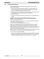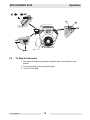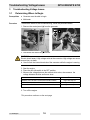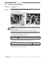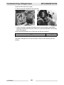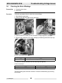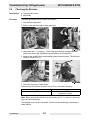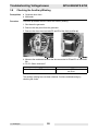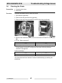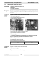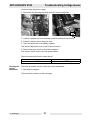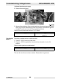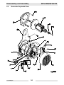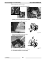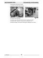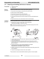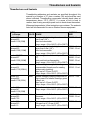
1
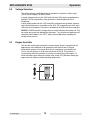
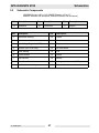
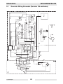
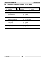
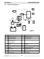
0174423en 0809 Generator GS 8.5V GPS 8500 GS 9.7V GPS 9700 REPAIR MANUAL 0 1 7 4 4 2 3 E N 002 GPS 8500/GPS 9700 Foreword Foreword Machines covered by this manual Machine documentation Expectations for information in this manual Copyright notice Machine Item Number GPS 8500 (GS 8.5V) 0008286 GPS 9700 (GS 9.7V) 0008287 GPS 9700 0620264 Keep a copy of the Operator’s Manual with the machine at all times. Use the separate Parts Book supplied with the machine to order replacement parts. Refer to the separate Repair Manual for detailed instructions on servicing and repairing the machine. If you are missing any of these documents, please contact Wacker Neuson Corporation to order a replacement or visit www.wackerneuson.com. When ordering parts or requesting service information, be prepared to provide the machine model number, item number, revision number, and serial number. This manual provides information and procedures to safely operate and maintain the above Wacker Neuson model(s). For your own safety and to reduce the risk of injury, carefully read, understand, and observe all instructions described in this manual. Wacker Neuson Corporation expressly reserves the right to make technical modifications, even without notice, which improve the performance or safety standards of its machines. The information contained in this manual is based on machines manufactured up until the time of publication. Wacker Neuson Corporation reserves the right to change any portion of this information without notice. All rights, especially copying and distribution rights, are reserved. Copyright 2009 by Wacker Neuson Corporation. This publication may be reproduced through photocopying by the original purchaser of the machine. Any other type of reproduction is prohibited without express written permission from Wacker Neuson Corporation. Any type of reproduction or distribution not authorized by Wacker Neuson Corporation represents an infringement of valid copyrights, and violators will be prosecuted. CALIFORNIA Proposition 65 Warning: Engine exhaust, some of its constituents, and certain vehicle components, contain or emit chemicals known to the State of California to cause cancer and birth defects or other reproductive harm. Laws pertaining to spark arresters NOTICE: State Health Safety Codes and Public Resources Codes specify that in certain locations spark arresters be used on internal combustion engines that use hydrocarbon fuels. A spark arrester is a device designed to prevent accidental discharge of sparks or flames from the engine exhaust. Spark arresters are qualified and rated by the United States Forest Service for this purpose. In order to comply wc_tx000827gb.fm 3 Foreword GPS 8500/GPS 9700 with local laws regarding spark arresters, consult the engine distributor or the local Health and Safety Administrator. Trademarks wc_tx000827gb.fm All trademarks referenced in this manual are the property of their respective owners. 4 GPS 8500/GPS 9700 1 Foreword 3 Safety Information 7 1.1 1.2 1.3 1.4 2 12 Control Panel ...................................................................................... 12 Voltage Selection ............................................................................... 13 Engine Auto Idle ................................................................................. 13 To Run the Generator ........................................................................ 14 To Stop the Generator ........................................................................ 15 Troubleshooting Voltage Issues 3.1 3.2 3.3 3.4 3.5 3.6 3.7 3.8 3.9 3.10 3.11 3.12 4 Laws Pertaining to Spark Arresters ...................................................... 7 Operating Safety .................................................................................. 8 Operator Safety While Using Internal Combustion Engines ................. 9 Service Safety .................................................................................... 10 Operation 2.1 2.2 2.3 2.4 2.5 3 Table of Contents Determining Where to Begin .............................................................. 16 Flashing the Generator ....................................................................... 18 Checking the Automatic Voltage Regulator (AVR) ............................. 20 Checking the Stator Windings ............................................................ 21 Checking the Rotor Windings ............................................................. 23 Checking the Brushes ........................................................................ 24 Checking the Diode Rectifier .............................................................. 25 Checking the Auxiliary Winding .......................................................... 26 Checking the Choke ........................................................................... 27 Checking the Transformer .................................................................. 28 Checking the Voltage Selector Switch (VSS) ..................................... 29 Checking the Auto Idle Circuit ............................................................ 30 Disassembly and Assembly 4.1 4.2 16 33 Tools Required for Disassembly/Assembly Procedures ..................... 33 Information Regarding Replacement Parts ........................................ 33 wc_br0174423en_002TOC.fm 5 Table of Contents 4.3 4.4 4.5 4.6 4.7 4.8 4.9 4.10 4.11 5 Information Regarding Reference Numbers ( ) ...................................33 Information Regarding Threadlocking Compounds .............................33 Generator Exploded View ...................................................................34 Exploded View Components ...............................................................35 Removing & Installing the Fuel Tank ...................................................36 Removing & Installing the Automatic Voltage Regulator (AVR) ..........37 Removing the Stator and Rotor ...........................................................38 Installing the Stator and Rotor .............................................................41 Removing and Installing the Electronic Governor ...............................44 Schematics 5.1 5.2 5.3 5.4 5.5 6 GPS 8500/GPS 970 46 Generator Wiring Schematic ...............................................................46 Schematic Components ......................................................................47 Generator Wiring Schematic (Revision 104 and below) ......................48 Schematic Components (Revision 104 and below) .............................49 Engine Wiring Diagram .......................................................................50 Technical Data 6.1 6.2 6.3 51 Generator ............................................................................................51 Windings ..............................................................................................51 Engine .................................................................................................52 wc_br0174423en_002TOC.fm 6 GPS 8500/GPS 9700 1 Safety Information Safety Information This manual contains DANGER, WARNING, CAUTION, NOTICE, and NOTE callouts which must be followed to reduce the possibility of personal injury, damage to the equipment, or improper service. This is the safety alert symbol. It is used to alert you to potential personal injury hazards. Obey all safety messages that follow this symbol to avoid possible injury or death. DANGER indicates a hazardous situation which, if not avoided, will result in death or serious injury. DANGER WARNING indicates a hazardous situation which, if not avoided, could result in death or serious injury. WARNING CAUTION indicates a hazardous situation which, if not avoided, could result in minor or moderate injury. CAUTION NOTICE: Used without the safety alert symbol, NOTICE indicates a situation which, if not avoided, could result in property damage. Note: Contains additional information important to a procedure. 1.1 Laws Pertaining to Spark Arresters Notice: State Health Safety Codes and Public Resources Codes specify that in certain locations spark arresters be used on internal combustion engines that use hydrocarbon fuels. A spark arrester is a device designed to prevent accidental discharge of sparks or flames from the engine exhaust. Spark arresters are qualified and rated by the United States Forest Service for this purpose. In order to comply with local laws regarding spark arresters, consult the engine distributor or the local Health and Safety Administrator. wc_si000252gb.fm 7 Safety Information 1.2 GPS 8500/GPS 9700 Operating Safety DANGER WARNING BACKFEED FROM THE GENERATOR INTO THE PUBLIC POWER DISTRIBUTION SYSTEM CAN CAUSE SERIOUS INJURY OR DEATH TO UTILITY WORKERS! Improper connection of generator to a building’s electrical system can allow electrical current from the generator to backfeed into utility lines. This may result in electrocution of utility workers, fire, or explosion. Connections to a building’s electrical system must be made by a qualified electrician and comply with all applicable laws and electrical codes. If connected to a building’s electrical system the generator must meet the power, voltage, and frequency requirements of the equipment in the building. Differences in power, voltage, and frequency requirements may exist and improper connection may lead to equipment damage, fire, and personal injury or death. Familiarity and proper training are required for the safe operation of the machine. Machines operated improperly or by untrained personnel can be hazardous. Read the operating instructions contained in this manual and the engine manual, and familiarize yourself with the location and proper use of all controls. Inexperienced operators should receive instruction from someone familiar with the machine before being allowed to operate it. 1.2.1 NEVER operate the generator when open containers of fuel, paint, or other flammable liquids are near. 1.2.2 NEVER operate the generator, or tools attached to the generator, with wet hands. 1.2.3 NEVER use worn electrical cords. Severe electrical shock and equipment damage may result. 1.2.4 NEVER run the electrical cords under the generator, or over vibrating or hot parts. 1.2.5 NEVER enclose or cover the generator when it is in use or when it is hot. 1.2.6 NEVER overload the generator. The total amperage of the tools and equipment attached to the generator must not exceed the load rating of the generator. 1.2.7 NEVER operate the machine in snow, rain, or standing water. 1.2.8 NEVER allow untrained personnel to operate or service the generator. The generator set should be set up by a certified electrician. 1.2.9 Store the machine properly when it is not being used. The machine should be stored in a clean, dry location out of the reach of children. 1.2.10 Be sure the machine is on a firm, level surface and will not tip, roll, slide, or fall while operating. wc_si000252gb.fm 8 GPS 8500/GPS 9700 1.3 Safety Information 1.2.11 ALWAYS transport the generator in an upright position. 1.2.12 ALWAYS keep the machine at least one meter (three feet) away from structures, buildings, and other equipment during use. 1.2.13 ALWAYS keep the area immediately surrounding and underneath the machine clean, neat, and free of debris and combustible materials. Make sure that the area overhead is clear of debris that could fall onto or into the machine or exhaust compartment. 1.2.14 ALWAYS remove all tools, cords, and other loose items from the generator before starting it. 1.2.15 ALWAYS make certain the machine is well-grounded and securely fastened to a good earthen ground per national and local regulations. Operator Safety While Using Internal Combustion Engines WARNING Internal combustion engines present special hazards during operation and fueling. Read and follow the warning instructions in the engine owner’s manual and the safety guidelines below. Failure to follow the warnings and safety standards could result in severe injury or death. 1.3.1 NEVER use this generator inside a home or garage, EVEN IF doors and windows are open. Only use OUTSIDE and far away from windows, doors, and vents. Using a generator indoors CAN KILL YOU IN MINUTES. Generator exhaust contains carbon monoxide. This is a poison you cannot see or smell. 1.3.2 NEVER use a generator inside an enclosed area such as a tunnel or a trench. 1.3.3 Do not smoke while operating the machine. 1.3.4 Do not smoke when refueling the engine. 1.3.5 Do not refuel a hot or running engine. 1.3.6 Do not refuel the engine near an open flame. 1.3.7 Do not spill fuel when refueling the engine. 1.3.8 Do not run the engine near open flames. 1.3.9 Do not start the engine if fuel has spilled or a fuel odor is present. Move the generator away from the spill and wipe the generator dry before starting. 1.3.10 Refill the fuel tank in a well-ventilated area. 1.3.11 Replace the fuel tank cap after refueling. 1.3.12 ALWAYS check the fuel lines and the fuel tank for leaks and cracks before starting the engine. Do not run the machine if fuel leaks are present or the fuel lines are loose. wc_si000252gb.fm 9 Safety Information 1.4 GPS 8500/GPS 9700 Service Safety WARNING Poorly maintained equipment can become a safety hazard! In order for the equipment to operate safely and properly over a long period of time, periodic maintenance and occasional repairs are necessary. If the generator is experiencing problems or is being serviced, attach a “DO NOT START” sign to the control panel to notify other people of its condition. 1.4.1 Do not use gasoline or other types of fuels or flammable solvents to clean parts, especially in enclosed areas. Fumes from fuels and solvents can become explosive. 1.4.2 DO NOT attempt to clean or service the machine while it is running. 1.4.3 Do not modify the machine without the express written approval of the manufacturer. 1.4.4 DO NOT allow water to accumulate around the base of the machine. If water is present, move the machine and allow the machine to dry before servicing. 1.4.5 DO NOT service the machine if your clothing or skin is wet. 1.4.6 DO NOT allow untrained personnel to service this equipment. Only trained electrical technicians should be allowed to service the electrical components of this equipment. 1.4.7 Keep the machine clean and labels legible. Replace all missing and hard-to-read labels. Labels provide important operating instructions and warn of dangers and hazards. 1.4.8 ALWAYS replace the safety devices and guards after repairs and maintenance. 1.4.9 ALWAYS let the engine cool before transporting or servicing the machine. 1.4.10 ALWAYS keep hands, feet, and loose clothing away from the moving parts on the generator and engine. 1.4.11 ALWAYS turn the engine off before servicing the machine. If the engine has electric start, disconnect the negative terminal on the battery before servicing the machine. 1.4.12 ALWAYS keep the fuel lines in good condition and properly connected. Leaking fuel and fumes are extremely explosive. wc_si000252gb.fm 10 GPS 8500/GPS 9700 Safety Information Notes wc_si000252gb.fm 11 Operation 2 GPS 8500/GPS 9700 Operation 2.1 Control Panel a c b d e 000000 20 A 30 A IDLE f f 120 120 f1 g f2 120/ 240 120 h j 20 A 30 A 120/240 240 n m 30 A 20 A Ref. k Description Ref. Description a Auto Idle Switch g Thermal Overload b Main Circuit Breaker h Voltage Selector Switch c 240V 20A Overcurrent Circuit Breaker j 120V 30A Twist-lock Receptacle d 120/240V 30A Overcurrent Circuit Breaker k 120V 20A Twist-lock Receptacle e Hour meter m 240V 20A Twist-lock Receptacle f 120V GFI Duplex Receptacle n 120/240V Twist-lock Receptacle wc_tx001265gb.fm 12 GPS 8500/GPS 9700 2.2 Operation Voltage Selection The voltage selector switch (h) allows the generator to operate in either single (120V) or dual voltage (120/240V) mode. In single voltage mode only the 120V twist lock and 120V duplex receptacles are powered. The full rated power of the generator is shared between the four receptacles. In dual voltage mode both the 120V and 240V receptacles are powered; however, only half the rated power is available at the 120V GFI receptacles and half at the 120V twist lock receptacle. Full power is available at the 240V twist lock receptacle. NOTICE: NEVER switch the voltage selector switch with the main breaker on! This can cause arcing and can damage the generator. Turn all tools and appliances off and place main breaker in the “OFF” (open) position (O) before changing the voltage switch position. 2.3 Engine Auto Idle The auto idle switch (a) automatically reduces engine speed 5 seconds after all appliances or tools attached to the generator have been turned off. Engine automatically returns to full speed when a tool or appliance is turned back on. To turn auto idle feature on, push auto idle switch to ON (I). This position is recommended while the generator is running to minimize fuel consumption. To avoid extended engine warm-up periods, keep switch OFF (O) when starting the engine and until engine reaches operating temperature. wc_tx001265gb.fm 13 Operation 2.4 GPS 8500/GPS 9700 To Run the Generator Follow instructions below and read starting and stopping instuctions found in Engine Owner’s Manual. 1. Ensure that the generator is properly installed in an outdoor location. See Sections Installation and Operator Safety while using Internal Combustion Engines for installation warnings and safety guidelines. 2. Disconnect all loads from the generator and place the main circuit breaker in the open (O) position. Place auto idle switch to OFF (O) position. 3. Open fuel valve (b1). 4. If engine is cold, pull choke control out (a1). If engine is hot, push choke control in (a2). 5. Turn key switch to the start position (d3) and hold until engine starts. NOTICE: Do not crank engine longer than 15 seconds at a time. Extended cranking can damage starter motor. To start engine using manual start: Turn key switch to the run position (d2). Pull starter rope (c) rapidly to start engine. Leave key in run position (d2) while engine is running. Note: Turn the keyswitch to the OFF position when the engine is not running. Leaving the key in the RUN position with the engine off will drain the battery. Note: Although the engine will start manually and will run without a battery, it will only idle and the generator will not load, as the governor requires that a battery be connected. See “Recommended Battery.” Note: The engine is equipped with a low oil protection system. If the oil level is low, the engine will not start. Check engine oil level if engine does not start. 6. Push choke in as engine warms (a2). 7. Place main circuit breaker in closed (l) position and place auto idle switch in ON (l) position. Allow engine to warm up and check function of GFI circuit breakers before attaching loads to generator (see Ground Fault Circuit Interrupt). wc_tx001265gb.fm 14 GPS 8500/GPS 9700 2.5 Operation To Stop the Generator 1. Disconnect all loads from generator and place main circuit breaker in open position. 2. Turn engine switch to the stop position (d1). 3. Close fuel valve (b2). wc_tx001265gb.fm 15 Troubleshooting Voltage Issues 3 3.1 GPS 8500/GPS 9700 Troubleshooting Voltage Issues Determining Where to Begin Prerequisites Procedure Generator must be able to begin Multimeter To determine where to start troubleshooting, follow the procedure below. 1. Remove the control panel (a) from the generator. F 1000 200 20 V 2 200m A V- COM 2. Disconnect the main wiring connector. WARNING Electric shock hazard. High voltage exists at the connector. High voltage can cause severe injury or death. f Never touch the internal terminals of the connector while the engine is running. 3. Start the engine. 4. Place the auto idle switch in the OFF position. 5. Measure the voltage between the red and white wires; also measure the voltage between the blue and brown wires. If Then Between 100–140 VAC is measured in both locations, begin with step 10. If 1.5 VAC or lower is measured in both locations, begin with step 1. If more than 1.5 VAC is measured in both locations, begin with step 2. 6. Turn off the engine. This procedure continues on the next page. wc_tx000828gb.fm 16 GPS 8500/GPS 9700 Troubleshooting Voltage Issues Continued from the previous page. Sequence Follow the sequence below when troubleshooting: Step wc_tx000828gb.fm Task 1 Flash the generator. See section Flashing the Generator. 2 Check the Automatic Voltage Regulator (AVR). See section Checking the Automatic Voltage Regulator (AVR). 3 Check the stator windings. See section Checking Stator Winding. 4 Check the rotor winding. See section Checking the Rotor Winding. 5 Check the brushes. See section Checking the Brushes. 6 Check the diode rectifier. See section Checking the Diode Rectifier. 7 Check the auxiliary winding. See section Checking the Auxiliary Winding. 8 Check the choke. See section Checking the Choke 9 Check the transformer. See section Checking the Transformer. 10 Check the Voltage Selector Switch (VSS). See section Checking the Voltage Selector Switch. 17 Troubleshooting Voltage Issues 3.2 GPS 8500/GPS 9700 Flashing the Generator Prerequisites Procedure 12V battery Multimeter Follow the procedure below to flash the generator. 1. Shut down the generator. 2. Disconnect all loads from the generator. 3. Place the auto idle switch in the OFF position. 4. Remove the rear panel (a) from the generator. 5. Disconnect the F1 (+) and F2 (-) wires and the L1 and L2 wires from the Automatic Voltage Regulator (AVR) (b). WARNING Electric shock hazard. High voltage exists at the L1 and L2 wires. Electric shock can cause severe injury or death. f Never touch the L1 and L2 wires while the engine is running. 6. Start the engine. 7. Check the engine rpm. It should be approximately 3750 rpm. WARNING Explosion hazard. Batteries produce hydrogen gas during normal operation. f Keep sparks away from the battery. 8. Connect the 12V battery to the F1 (+) and F2 (-) wires; battery positive to F 1 (+), battery negative to F2 (-). 9. Measure the voltage between the L1 wire and the L2 wire. Is 120–160 VAC measured? Yes ____ No ____ Continue Check the stator windings. 10.Reassemble the generator. This procedure continues on the next page. wc_tx000828gb.fm 18 GPS 8500/GPS 9700 Troubleshooting Voltage Issues Continued from the previous page. 11.Measure the voltage at the receptacles. Is the correct voltage measured? Yes ____ No ____ The generator is ready for use. Continue troubleshooting by checking the automatic voltage regulator (AVR). The flashing procedure is now complete. wc_tx000828gb.fm 19 Troubleshooting Voltage Issues 3.3 GPS 8500/GPS 9700 Checking the Automatic Voltage Regulator (AVR) Prerequisites Procedure Generator shut down Multimeter Follow the procedure below to check the Automatic Voltage Regulator (AVR). 1. Shut down the generator. 2. Disconnect all loads from the generator. 3. Place the auto idle switch in the OFF position. 4. Remove the rear panel (a) from the generator. 5. Disconnect the F1 (+) and F2 (-) wires and the L1 and L2 wires from the Automatic Voltage Regulator (AVR) (b). WARNING Electric shock hazard. High voltage exists at the L1 and L2 wires. Electric shock can cause severe injury or death. f Never touch the L1 and L2 wires while the engine is running. 6. Start the engine. 7. Check the engine rpm. It should be approximately 3750 rpm. 8. Measure the voltage between the L1 wire and the L2 wire. Is 120–160 VAC measured? Yes ____ No ____ The AVR has failed; replace it. No judgement can be made on the AVR. The AVR has now been checked. Continue with checking the stator windings. wc_tx000828gb.fm 20 GPS 8500/GPS 9700 3.4 Troubleshooting Voltage Issues Checking the Stator Windings Prerequisites Procedure Generator shut down Multimeter Follow the procedure below to check the stator windings. 1. Shut down the generator. 2. Remove the front panel (a) from the generator. F 1000 200 20 V 2 200m A V- COM wc_gr004673 3. Disconnect the main wiring connector. WARNING Electric shock hazard. High voltage exists at the connector. High voltage can cause severe injury or death. f Never touch the internals of the connector while the engine is running. 4. Measure the resistance between the red and white wires; also measure the resistance between the blue and brown wires. Is 0.2–0.3 Ohms measured in each case? Yes ____ No ____ Continue. The stator windings have failed; replace the stator. 5. Check if the stator winding is shorted to ground by checking the continuity between each wire (red, white, blue, and brown) and ground. Is there continuity? Yes ____ No ____ The stator windings have failed; replace the stator. Continue. This procedure continues on the next page. wc_tx000828gb.fm 21 Troubleshooting Voltage Issues GPS 8500/GPS 9700 Continued from the previous page. 6. Remove the end cap (b) from the generator. b c d wc_gr004870 7. Check if the stator windings are shorted to the rotor winding by checking the continuity between each wire (red, white, blue, and brown) and the rotor winding at the slip rings (c). Is there continuity between any of the wires and the rotor winding? Yes ____ No ____ The stator windings have failed; replace the stator. Continue. The stator windings have now been checked. Continue with checking the rotor winding. wc_tx000828gb.fm 22 GPS 8500/GPS 9700 3.5 Troubleshooting Voltage Issues Checking the Rotor Windings Prerequisites Generator shut down Multimeter Procedure Follow the procedure below to check the rotor windings. 1. Shut down the generator. 2. Remove the rear panel (a) from the generator. 3. Remove the brush holder and the Automatic Voltage Regulator (AVR) (b). 4. Measure the resistance of the rotor winding by measuring across the slip rings. F 1000 200 20 V 2 200m A V- COM Is 12.3–12.8 Ohms measured? Yes ____ No ____ Continue. The rotor winding has failed; replace the rotor. 5. Check for continuity between the rotor slip rings and ground. Is there continuity? Yes ____ No ____ The rotor has failed; replace it. The rotor winding is OK. The rotor winding has now been checked. Continue troubleshooting by checking the brushes. wc_tx000828gb.fm 23 Troubleshooting Voltage Issues 3.6 GPS 8500/GPS 9700 Checking the Brushes Prerequisites Procedure Generator shut down Multimeter Follow the procedure below to check the brushes. 1. Shut down the generator. 2. Remove the rear panel (a) from the generator. 3. Disconnect the F1 (+) and F2 (-) wires from the Automatic Voltage Regulator (AVR) and remove the AVR (b) and brush holder from the machine. 4. Measure the length of the brush protruding from the brush holder. The minimum length is 8 mm (0.32 in.). 5. Check the continuity of each brush. Does each brush measure at least 8 mm (0.32 in.) and have continuity? Yes ____ No ____ The brushes are OK. The brushes have failed. Replace the brushes. Note: When reconnecting the wires to the brushes, the F1 (+) wire runs to the slip ring closest to the bearing. The brushes have now been checked. Continue troubleshooting by checking the diode rectifier. wc_tx000828gb.fm 24 GPS 8500/GPS 9700 3.7 Troubleshooting Voltage Issues Checking the Diode Rectifier Prerequisites Procedure Generator shut down Multimeter Follow the procedure below to check the diode rectifier. 1. Shut down the generator. 2. Remove the rear panel from the generator. 3. Mark, then disconnect the wires from the diode rectifier (a). 4. Using the diode scale on the multimeter, check the continuity of the diode rectifier. Check: F1 to Z2, F1 to F2, F1 to Z3 F2 to Z3, F2 to F1, F2 to Z2 Z2 to F2, Z2 to Z3, Z2 to F1 Z3 to F1, Z3 to Z2, Z3 to F2. 5. Reverse the leads and check again. Note: For each check, the multimeter should read approximately 0.5V in one direction and “OPEN” in the other. Does the diode rectifier perform as stated above? Yes ____ No ____ The diode rectifier is OK. The diode rectifier has failed; replace it. The diode rectifier has now been checked. Continue troubleshooting by checking the auxiliary winding. wc_tx000828gb.fm 25 Troubleshooting Voltage Issues 3.8 GPS 8500/GPS 9700 Checking the Auxiliary Winding Prerequisites Procedure Generator shut down Multimeter Follow the procedure below to check the auxiliary winding. 1. Shut down the generator. 2. Remove the rear panel from the generator. 3. Remove the wires from terminals Z2 and Z3 of the diode rectifier (a). 4. Measure the resistance between the wire connected to Z2 and Z1 on the choke (b). Is 1.8–2.0 Ohms measured? Yes ____ No ____ The auxiliary winding is OK. The auxiliary winding has failed. Replace the choke. The auxiliary winding has now been checked. Continue troubleshooting by checking the choke. wc_tx000828gb.fm 26 GPS 8500/GPS 9700 3.9 Troubleshooting Voltage Issues Checking the Choke Prerequisites Procedure Generator shut down Multimeter Follow the procedure below to check the choke. 1. Shut down the generator. 2. Remove the rear panel from the generator. 3. Remove the wires from terminals Z2 and Z3 of the diode rectifier (a). 4. Measure the resistance between the wire connected to Z3 and Z1 on the choke (b). Is 7.6–8.1 Ohms measured? Yes ____ No ____ Continue. The choke has failed. Replace the choke. 5. Check if the choke is shorted to ground by the checking continuity (O.1–1.0 Ohms) between terminal Z3 and ground. Also check continuity between terminal Z1 and ground. Is there continuity? Yes ____ No ____ The choke has failed. Replace the choke. The choke is OK. The choke has now been checked. Continue troubleshooting by checking the transformer. wc_tx000828gb.fm 27 Troubleshooting Voltage Issues 3.10 GPS 8500/GPS 9700 Checking the Transformer Prerequisites Generator shut down Multimeter Background The transformer consists of three windings. Each needs to be checked when checking the condition of the transformer. Procedure Follow the procedure below to check the transformer. 1. Remove the front panel (a) from the generator. 2. Locate the transformer (b) within the control box. 3. Trace the brown wire and the blue wire coming out of the transformer. The brown wire runs to terminal 6 of the Voltage Selector Switch (VSS). The blue wire runs to terminal 10 of the VSS. 4. Measure the resistance between the brown wire and the blue wire. Is 810–890 Ohms measured? Yes ____ No ____ Continue. The transformer has failed; replace it. 5. Trace the red wire and the white wire coming out of the transformer. The red wire runs to the main circuit breaker. The white wire runs to the neutral side of the 125V GFCI receptacle. 6. Measure the resistance between the red wire and the white wire. Is 630–690 Ohms measured? Yes ____ No ____ Continue. The transformer has failed; replace it. 7. Trace the orange wire and the yellow wire coming out of the transformer. Both wires run to the Automatic Voltage Regulator (AVR). 8. Measure the resistance between the orange wire and the yellow wire. Is 450–490 Ohms measured? Yes ____ No ____ The transformer is OK. The transformer has failed; replace it. The transformer has now been checked. Continue by checking the VSS. wc_tx000828gb.fm 28 GPS 8500/GPS 9700 3.11 Troubleshooting Voltage Issues Checking the Voltage Selector Switch (VSS) Prerequisites Procedure Machine shutdown Multimeter Follow the procedure below to check the Voltage Selector Switch (VSS) 1. Place the VSS in the 120V position. 2. Remove the switch handle (a). 3. Remove the screws that secure the VSS (b) to the control panel. 4. Label the wires connected to the VSS. 5. Remove the wires connected to the VSS. 6. Reconnect the switch handle to the switch. 7. Check the resistance between the terminals. Position Closed terminals Open terminals 120 1–2; 5–6; 9–10 3–4; 7–8; 11–12 240 3–4; 7–8; 11–12 1–2; 5–6; 9–10 Your meter should read less than 1 Ohm for closed terminals and “OL” or “OPEN” for open terminals. Does the switch perform as stated above? Yes ____ No ____ The VSS is OK. The VSS has failed; replace it. 8. Reassemble the generator. The VSS has now been checked. wc_tx000828gb.fm 29 Troubleshooting Voltage Issues 3.12 GPS 8500/GPS 9700 Checking the Auto Idle Circuit Prerequisites Machine’s battery must measure 12V Multimeter 14-gauge jumper wire Background The idle is controlled by the engine electronic governor system (control module and motorized actuator) and the switch and current transformer. Each component must be checked. Checking the control module Follow the procedure below to check the control module. 1. Shut down the generator. 2. Disconnect all loads from the generator. 3. Locate the control module (a). wc_gr004701 4. Remove the loom (harness) to expose the wires. 5. Disconnect the blue wire at the connector. 6. Start the engine. 7. Connect the jumper wire to the module’s blue wire and connect it to ground. After a 10-second delay the engine should idle down to 1750 rpm. 8. Remove the ground wire. The engine should return to 3600 rpm. Does the module perform as stated above? Checking the actuator Yes ____ No ____ Continue. The module has failed; replace it. Follow the procedure below to check the actuator. 1. Shut down the engine. This procedure continues on the next page. wc_tx000828gb.fm 30 GPS 8500/GPS 9700 Troubleshooting Voltage Issues Continued from the previous page. 2. Disconnect the red and green wires from the control module (a). 3. Connect a jumper wire from the battery positive terminal to the red wire. 4. Connect a jumper wire to the green wire. 5. Touch the green wire to the battery negative. The actuator (b) should move to the full-speed position. 6. Remove the green wire from the battery negative. The actuator should move to the low-speed position. Does the actuator perform as stated above? Checking the current transformer Yes ____ No ____ The actuator is OK; continue. The actuator has failed; replace it. Follow the procedure below to check the current transformer. 1. Shut down the engine. This procedure continues on the next page. wc_tx000828gb.fm 31 Troubleshooting Voltage Issues GPS 8500/GPS 9700 Continued from the previous page. 2. Remove the control panel. 3. Measure the resistance of the current transformer by measuring across the two wires of the current transformer (c). One of the wires is connected to a ground stud (d). The other is connected to the auto idle switch (e). Does the current transformer measure 70–73 Ohms? Checking the switch Yes ____ No ____ The current transformer is OK; continue. The current transformer has failed; replace it. Follow the procedure below to check the switch. 1. Check for 12VDC incoming to the switch. 2. Check for 12VDC outgoing from the switch when the switch is in the ON position. Does the switch perform as stated above? Yes ____ No ____ The switch is OK. The switch has failed; replace it. The auto idle circuit has now been checked. Reassemble the generator. wc_tx000828gb.fm 32 GPS 8500/GPS 9700 4 4.1 Disassembly and Assembly Tools Required for Disassembly/Assembly Procedures 4.2 It is up to the mechanic to use common sense and good judgment in tool selection to reduce the risk of injury while repairing the machine. In cases where a special tool is required, the special tool is listed in the prerequisite section of the procedure. Before substituting another tool or procedure from those recommended in this manual, the mechanic must be satisfied that neither personal injury nor damage to the machine will result due to the substitution. Information Regarding Replacement Parts 4.3 Disassembly and Assembly The repair procedures contained in this manual do not include part numbers. For replacement parts information, refer to the Parts Book originally supplied with the machine. If the original Parts Book has been lost, a replacement may be ordered from Wacker Neuson Corporation. When ordering a replacement Parts Book, please list the model number, item number, revision level, and serial number of the machine. Parts Books are also available on the Wacker Neuson Corporation Web site. See www.wackerneuson.com. Enter the site as a visitor. Information Regarding Reference Numbers ( ) Repair procedures contain reference numbers enclosed in parentheses ( ). These numbers refer to the item numbers shown on the assembly drawings and other detailed drawings. They are included to aid the mechanic in identifying parts and assembling components. 4.4 Information Regarding Threadlocking Compounds Background Due to the heavy vibration inherent in this type of equipment, the repair and service procedures described in this manual specify the use of threadlocking compounds. These compounds should be used where indicated to prevent the fasteners from becoming loose. Recommended Although Loctite® is referred to throughout this manual, any equivalent type of threadlockers sealant such as Hernon®, Prolock, or Omnifit may be used. For a complete list of recommended sealing and locking compounds, refer to the Use of Threadlockers and Sealants chart at the end of this manual. Applying threadlockers wc_tx000829gb.fm Clean the screw threads and wipe off any oil or grease before applying a threadlocking compound. 33 Disassembly and Assembly 4.5 GPS 8500/GPS 9700 Generator Exploded View wc_tx000829gb.fm 34 GPS 8500/GPS 9700 4.6 Disassembly and Assembly Exploded View Components Ref. Ref. Description a Mounting plate n Choke b Stud o Screw c Rotor p Cover d Bearing q Screw e Nut r Brush holder f --- s Automatic Voltage Regulator (AVR) g Lifting plate t Screw h Nut u Brush i Stator v Nut j Diode rectifier w Screw k Screw x Stator winding connector l --- y Ground Screw z --- m wc_tx000829gb.fm Description 35 Disassembly and Assembly 4.7 GPS 8500/GPS 9700 Removing & Installing the Fuel Tank Prerequisites Removal procedure Engine shut down Engine cool Plug for fuel hose Wire ties Follow the procedure below to remove the fuel tank. 1. Disconnect the fuel hose from the engine and plug the hose (a). 2. Cut the wire ties that secure the fuel hose to the wiring harness. 3. Remove the screws (b) that secure the fuel tank to the frame. 4. Pull the fuel tank from the frame. Installation procedure Follow the procedure below to install the fuel tank. 1. Position the fuel tank onto the frame. 2. Secure the fuel tank to the frame with screws (b). 3. Connect the fuel hose to the engine. 4. Secure the fuel hose to the wiring harness with new wire ties. The procedure to replace the fuel tank is now complete. wc_tx000829gb.fm 36 GPS 8500/GPS 9700 4.8 Disassembly and Assembly Removing & Installing the Automatic Voltage Regulator (AVR) Prerequisites Removal procedure Engine shut down New brushes Follow the procedure below to remove the Automatic Voltage Regulator (AVR). 1. Remove the cover (a) from the generator. 2. Remove the screws that secure the mounting bracket to the stator. 3. Label, then remove the wires connected to the AVR (b). 4. Remove the screw that secures the AVR to the brush holder. Installation procedure Follow the procedure below to install the AVR. 1. Secure the AVR to the brush holder. 2. Connect the wires to the AVR. 3. Secure the mounting bracket to the stator. Adjusting procedure Follow the procedure below to adjust the AVR. 1. Start the engine and verify rpm, it must be 3600 no load. WARNING Electric shock hazard. High voltage exists at L1 and L2 of the AVR when the engine is running. Electric shock can cause severe injury or death. f Do not touch L1 and/or L2 while making this adjustment. 2. Place the auto idle switch in OFF position. 3. Check the voltage at the receptacles. 4. Turn the adjusting pot (c) on the AVR so that 115–125VAC is measured at the 120V recptacles. Turn the adjusting pot clockwise to increase voltage, counterclockwise to decrease voltage. 5. Install the cover. The procedure to replace the AVR is now complete. wc_tx000829gb.fm 37 Disassembly and Assembly 4.9 GPS 8500/GPS 9700 Removing the Stator and Rotor Prerequisites Procedure Engine shut down Engine cool Two blocks of wood Follow the procedure below to remove the stator and rotor. 1. Remove the fuel tank. See section Removing and Installing the Fuel Tank. 2. Remove the AVR. See section Removing and Installing the AVR. 3. Remove the choke. See section Removing and Installing the Choke. 4. Remove the control panel (a). 5. Remove the ground wire (b) from the stator. 6. Remove the screw (c) that secures the battery cable. 7. Disconnect the blue wire at the auto idle switch (d). This procedure continues on the next page. wc_tx000829gb.fm 38 GPS 8500/GPS 9700 Disassembly and Assembly Continued from the previous page. 8. Remove the engine exhaust guard (e). 9. Remove the hardware (f) that secures the lifting eye. 10.Remove the ground wire (g) from the frame. g h wc_gr004718 11.Disconnect the main stator winding connector (h) and slide the connector out of the control box. 12.Slide the AVR wires out of the generator and into the control box. 13.Remove the screws and nuts (i) that secure the shock mount bracket to the stator. 14.Support (j) the engine to the frame. This procedure continues on the next page. wc_tx000829gb.fm 39 Disassembly and Assembly GPS 8500/GPS 9700 Continued from the previous page. 15.Remove the threaded rod (k) from the rotor. 16.Using a hammer and a block of wood, tap the stator to release it from the engine. Then, pull the stator off the engine. Note: On some occasions, the rotor may come out with the stator. If this happens, skip to “Separating the rotor from the stator”. 17.Support the rotor (l) with one hand and strike it with a rubber mallet on a pole face until it releases. Separating the Follow the procedure below to separate the rotor from the stator. rotor from the 1. Place the stator (m) on two blocks of wood with the bearing end up. Place the stator blocks of wood near the edge to allow the rotor space to drop out. 2. Partially insert one of the frame mounting screws (n) into the bearing. 3. Tap the screw with a dead blow hammer until the rotor separates from the stator. The procedure to remove the stator and the rotor is now complete. wc_tx000829gb.fm 40 GPS 8500/GPS 9700 4.10 Disassembly and Assembly Installing the Stator and Rotor Prerequisites Procedure Engine shut down Engine cool Follow the procedure below to install the stator and rotor. 1. Slide the rotor (l) onto the engine shaft. 2. Install the threaded rod (k) into the rotor. 3. Install the screws and nuts (i) that secure the shock mount bracket to the stator. 4. Slide the AVR wires out of the generator and into the control box. This procedure continues on the next page. wc_tx000829gb.fm 41 Disassembly and Assembly GPS 8500/GPS 9700 Continued from the previous page. 5. Connect the blue wire at the auto idle switch (d). 6. Install the screw (c) that secures the battery cable. 7. Connect the ground wire (g) to the frame. g h wc_gr004718 8. Slide the connector (h) into the control box. 9. Install the engine exhaust guard (e). 10.Install the hardware (f) that secures the lifting eye. This procedure continues on the next page. wc_tx000829gb.fm 42 GPS 8500/GPS 9700 Disassembly and Assembly Continued from the previous page. 11.Install the ground wire (b) to the stator. 12.Install the control panel (a). 13.Install the choke. See section Removing and Installing the Choke. 14.Install the AVR. See section Removing and Installing the AVR. 15.Install the fuel tank. See section Removing and Installing the Fuel Tank. wc_tx000829gb.fm 43 Disassembly and Assembly 4.11 GPS 8500/GPS 9700 Removing and Installing the Electronic Governor Prerequisites Removal procedure Engine shut down Engine cool Follow the procedure below to remove the electronic governor. 1. Disconnect the red and green wires from the control module. 2. Remove the air cleaner assembly. 3. Disconnect the governor link at the carburetor. 4. Remove the governor control bracket with the actuator. 5. Disconnect the governor link from the actuator and remove the throttle return spring. 6. Remove the screws, nuts, and actuator from the control bracket. Installation procedure Follow the procedure below to install the electronic governor. 1. Assemble the actuator to the governor control bracket (a). Torque the screws (b) to 3.4 Nm (30 in. lbs.). Note: Hold the long screws with a 1/4-inch wrench when torquing the nuts. The screws must not turn while torquing the nuts. 2. Connect the governor link to the actuator. Make sure the link snaps into the hole in the actuator grommet. 3. Connect the throttle return spring through the slot in the governor control bracket with the open end spring facing out and through the small hole in the governor bracket. 4. Connect the governor control bracket assembly to the engine. Torque the four 8 mm screws to 17 Nm (150 in. lbs.). Torque the two 6 mm screws to 10 Nm (70 in. lbs.). 5. Rotate the actuator lever to the position shown (c) and connect the governor link to the carburetor. 6. Connect the red and green wires to the control module. THe procedure to remove and install the electronic governor is now complete. wc_tx000829gb.fm 44 GPS 8500/GPS 9700 Disassembly and Assembly Notes wc_tx000829gb.fm 45 wc_tx000831gb.fm B Gr F1 R 5 F2 B L2 Y 46 Z2 Z3 Z3 Z1 Z2 F1 F2 9 Z1 G/Y 1 L Br L Br W R W R R/Gr 7 W R 10 3 4 2 1 11 L G/Y B 8 B R/G 17 L/G 6 1 2 3 4 5 6 7 8 3 7 9 L 4 2 8 6 L/B R/B 12 10 8 7 Br C B/G R/Y 120V 120/240V L/Y 18 R/L 18 W 15 G/W 14 B/G W B G/Y B/W R/W G/Y 120VAC 15A B/L B/L W/G B/Y B/Y W/Y Y R/Gr G 16 240VAC 20A B G/Y B G/Y G/W G/Y B/R G/Y 120VAC 120VAC 20A 15A 13 W/L W/R wc_gr004671 12 L 120/240VAC 30A G/Y Y/B Y/R G/Y 120VAC 30A B/Or B/Or W/Or 5.1 3 L1 O 2 1 B 5 4 A Schematics GPS 8500/GPS 9700 Schematics Generator Wiring Schematic (0008286 Revision 105 to 118; 0008287 Revision 105 to 117 0008287 Revision 200 and above; 0620264 Revision 200 and above) GPS 8500/GPS 9700 5.2 Schematics Schematic Components (0008286 Revision 105 to 118; 0008287 Revision 105 to 117 0008287 Revision 200 and above; 0620264 Revision 200 and above) Ref. Description A Generator Ref. Description Ref. Description Ref. B Control box C Ref. Description Engine Description 1 Main stator winding 10 Choke 2 Transformer 11 Hour meter 3 Auto Voltage Regulator (AVR) 12 Engine module 4 Resistor (GPS 9700 only) 13 Oil level switch 5 Rotor winding 14 Coil 6 Circuit breaker 15 Starter 7 Auto idle unit 16 Battery 8 Auto idle switch 17 Voltage selector switch (VSS) 9 Auxiliary stator winding 18 Terminal block wc_tx000831gb.fm 47 wc_tx000831gb.fm R F1 3 L1 O 5 F2 B L2 Y Z2 2 48 9 Z3 Z3 Z1 Z2 Z1 L Br Br W R W G/Y 1 L 1 R/Gr Br 7 W 10 3 4 2 1 R B 11 L W/O G/Y B 8 B R/G 17 L/G 6 2 8 5 6 7 6 1 4 7 5 8 3 2 3 4 1 3 7 9 L 4 2 8 6 L/B R/B 12 10 Br C B/G R/Y 120V 120/240V L/Y R/L 18 18 15 14 B/G W/G B G/Y B/W R/W G/Y 120VAC 15A B/L B/L B/Y B/Y 13 Y R/Gr G 16 240VAC 20A B G/Y B G/Y G/W G/Y B/R G/Y 120VAC 120VAC 20A 15A W/L W/Y W/R 12 L 120/240VAC 30A G/Y Y/B Y/R G/Y 120VAC 30A B/Or B/Or W/Or 5.3 4 A Schematics GPS 8500/GPS 9700 Generator Wiring Schematic (Revision 104 and below) GPS 8500/GPS 9700 5.4 Schematics Schematic Components (Revision 104 and below) Ref. Description A Generator Ref. Description Ref. Description Ref. B Control box C Ref. Description Engine Description 1 Main stator winding 10 Choke 2 Transformer 11 Hour meter 3 Auto Voltage Regulator (AVR) 12 Engine module 4 Resistor (GPS 9700 only) 13 Oil level switch 5 Rotor winding 14 Coil 6 Circuit breaker 15 Starter 7 Auto idle unit 16 Battery 8 Auto idle switch 17 Voltage selector switch (VSS) 9 Auxiliary stator winding 18 Terminal block wc_tx000831gb.fm 49 Schematics 5.5 Ref. GPS 8500/GPS 9700 Engine Wiring Diagram Description Ref. Description 1 Carburetor solenoid 10 Regulator rectifier 2 Stop switch terminal 11 DC output wire 3 50 Hz. loop (GPS 8500=yellow, GPS 9700=red) 12 Key switch 4 Module 13 Solenoid 5 Idle down device 14 Battery terminal 6 Actuator 15 Solenoid tab terminal 7 Ignition coils 16 Starter terminal 8 Alternator 17 Battery 9 AC output wires 18 Starter motor wc_tx000831gb.fm 50 GPS 8500/GPS 9700 6 Technical Data Technical Data 6.1 Generator Item No. GS 8.5V 0008286 GS 9.7V 0008287, 0620624 Generator Maximum Output kW / kVA Continuous Output 8.5 / 8.5 9.7 / 9.7 8.2 9.3 W Type Dual voltage, single phase, brush-type system AC Voltages Available 120 / 240 1ø volts phase Frequency 60 Hz Power Factor 1.0 AC receptacles: 120V GFI duplex 120V GFI duplex 120V twist lock 120V twist lock 240V twist lock 120/240V twist lock amp Continuous Current at 120V amp 20 20 20 30 20 30 LxWxH mm (in.) Weight (dry) Kg (lbs.) 6.2 68 77.5 800 x 635 x 603 (31.5 x 25 x 23.75) 97 (214) 99 (218) Windings wc_td000255gb.fm Machine Main (stator) Auxilliary Rotor Choke GPS 8500 (GS 8.5V) 0.20 1.62 11.9 7.5 GPS 9700 (GS 9.7V) 0.20 1.74 11.9 7.5 51 Technical Data 6.3 GPS 8500/GPS 9700 Engine Item No. GS 8.5V GS 8.5V GS 9.7V GS 9.7V 0008286 Rev 108 and lower 0008286 Rev 109 to 118 0008287 Rev 108 and lower 0008287 Rev 109 to 117 Engine Engine Type 2 cylinder, 4-cycle, air-cooled, gasoline engine Engine Make Briggs and Stratton Engine Model Vanguard Vanguard Vanguard Vanguard 303447 350447 350447 356447 Rated Power kW (Hp) 11.9 (16) 13.4 (18) Displacement cm3 (in3) 480 (29.3) 570 (34.75) Spark Plug Champion RC12YC Electrode Gap mm (in.) 0.76 (0.030) Starter type / V Electric / 12 Alternator amp 16 Engine Speed - full load rpm 3600 Auto Idle Speed rpm 2200 Valve Clearance (cold) Air Cleaner Battery Engine Lubrication Engine Oil Capacity Fuel Fuel Tank Capacity Fuel Consumption wc_td000255gb.fm 0.10–0.16 (0.004–0.006) mm (in.) Dual element type V/size/CCA 12 / 22NF / 230 oil grade SAE 10W30 SG, SF, or SE service class 1.6 (1.7) l (qts.) Regular unleaded gasoline type 28 (7.4) l (gal.) l (gal.)/hr. 5.03 (1.33) 52 6.21 (1.64) GPS 8500/GPS 9700 Technical Data Non CARB compliant Machines Engine power rating Gross power rating per SAE J1995. Actual power output may vary due to conditions of specific use. 0008286 0620264 Rev 200 and above Item No. GPS 8500 GPS 9700 Engine Engine type 2 cylinder, 4-cycle, air-cooled, gasoline engine Engine make Briggs and Stratton Engine model Vanguard Vanguard 305447 356447 Max. rated power @ rated speed kW (Hp) 11.9 (16) @ 3600 rpm 13.4 (18) @ 3600 rpm Displacement cm3 (in3) 480 (29.3) 570 (34.75) Spark plug Champion RC12YC Electrode gap mm (in.) 0.76 (0.030) Starter type / V Electric / 12 Alternator amp 16 Engine speed - operating rpm 3600 Auto idle speed rpm 2200 Valve clearance (cold) Air cleaner Battery Engine lubrication Engine oil capacity Fuel Dual element type V/size/CCA 12 / 22NF / 230 oil grade SAE 10W30 SG, SF, or SE service class 1.6 (1.7) l (qts.) Regular unleaded gasoline type Fuel tank capacity l (gal.) Fuel consumption l (gal.)/hr. wc_td000255gb.fm 0.10–0.16 (0.004–0.006) mm (in.) 28 (7.4) 5.03 (1.33) 53 6.21 (1.64) Technical Data GPS 8500/GPS 9700 CARB Compliant Machines Engine power rating Gross power rating per SAE J1995. Actual power output may vary due to conditions of specific use. 0008287 Item No. GPS 9700 Engine Engine Type 2 cylinder, 4-cycle, air-cooled, gasoline engine Engine Make Briggs and Stratton Engine Model Vanguard 356447 Max. rated power @ rated speed kW (Hp) 13.4 (18) @ 3600 rpm Displacement cm3 (in3) 570 (34.75) Spark Plug Champion RC12YC Electrode Gap mm (in.) 0.76 (0.030) Starter type / V Electric / 12 Alternator amp 16 Operating speed rpm 3600 Auto Idle Speed rpm 2200 Valve Clearance (cold) Air Cleaner Battery Engine Lubrication Engine Oil Capacity Fuel Fuel Tank Capacity Fuel Consumption wc_td000255gb.fm mm (in.) type 0.10–0.16 (0.004–0.006) Dual element V/size/CCA 12 / 22NF / 230 oil grade SAE 10W30 SG, SF, or SE service class l (qts.) type l (gal.) l (gal.)/hr. 54 1.6 (1.7) Regular unleaded gasoline 28 (7.4) 6.21 (1.64) Threadlockers and Sealants Threadlockers and Sealants Threadlocking adhesives and sealants are specified throughout this manual by a notation of “S” plus a number (S#) and should be used where indicated. Threadlocking compounds normally break down at temperatures above 175°C (350°F). If a screw or bolt is hard to remove, heat it using a small propane torch to break down the sealant. When applying sealants, follow instructions on container. The sealants listed are recommended for use on Wacker Neuson equipment. TYPE ( ) = Europe Loctite 222 Hernon 420 Omnifit 1150 (50M) COLOR USAGE Purple Low strength, for locking threads smaller than 6 mm (1/4”). Hand tool removable. Temp. range: -54 to 149°C (-65 to 300°F) Blue Medium strength, for locking threads Loctite 243 Hernon 423 larger than 6 mm (1/4”). Omnifit 1350 (100M) Hand tool removable. Temp. range: -54 to 149°C (-65 to 300°F) Loctite 271/277 Red High strength, for all threads up to 25 mm Hernon 427 (1”). Omnifit 1550 (220M) Heat parts before disassembly. Temp. range: -54 to 149°C (-65 to 300°F) Loctite 290 Green Medium to high strength, for locking Hernon 431 preassembled threads and for sealing Omnifit 1710 (230LL) weld porosity (wicking). Gaps up to 0.13 mm (0.005”) Temp. range: -54 to 149°C (-65 to 300°F) Loctite 609 Green Medium strength retaining compound for Hernon 822 slip or press fit of shafts, bearings, gears, Omnifit 1730 (230L) pulleys, etc. Gaps up to 0.13 mm (0.005”) Temp. range: -54 to 149°C (-65 to 300°F) Loctite 545 Brown Hydraulic sealant Hernon 947 Temp. range: -54 to 149°C (-65 to 300°F) Omnifit 1150 (50M) Loctite 592 White Pipe sealant with Teflon for moderate Hernon 920 pressures. Omnifit 790 Temp. range: -54 to 149°C (-65 to 300°F) Loctite 515 Purple Form-in-place gasket for flexible joints. Hernon 910 Fills gaps up to 1.3 mm (0.05”) Omnifit 10 Temp. range: -54 to 149°C (-65 to 300°F) PART NO. – SIZE 73287 - 10 ml 29311 - .5 ml 17380 - 50 ml 29312 - .5 ml 26685 - 10 ml 73285 - 50 ml 28824 - .5 ml 25316 - 10 ml 29314 - .5 ml 79356 - 50 ml 26695 - 6 ml 73289 - 50 ml 70735 - 50 ml Threadlockers and Sealants Threadlockers and Sealants (continued) Threadlocking adhesives and sealants are specified throughout this manual by a notation of “S” plus a number (S#) and should be used where indicated. Threadlocking compounds normally break down at temperatures above 175°C (350°F). If a screw or bolt is hard to remove, heat it using a small propane torch to break down the sealant. When applying sealants, follow instructions on container. The sealants listed are recommended for use on Wacker Neuson equipment. TYPE ( ) = Europe COLOR USAGE Loctite 496 Clear Instant adhesive for bonding rubber, Hernon 110 metal and plastics; general purpose. Omnifit Sicomet 7000 For gaps up to 0.15 mm (0.006”) Read caution instructions before using. Temp. range: -54 to 82°C (-65 to 180°F) Loctite Primer T Aerosol Fast curing primer for threadlocking, Hernon Primer 10 Spray retaining and sealing compounds. Must Omnifit VC Activator be used with stainless steel hardware. Recommended for use with gasket sealants. PART NO. – SIZE 52676 - 1oz. 2006124-6 oz. Torque Values Torque Values Metric Fasteners (DIN) TORQUE VALUES (Based on Bolt Size and Hardness) 8.8 10.9 WRENCH SIZE 12.9 Size Nm ft.lb. Nm ft.lb. Nm ft.lb. Metric Inch Metric Inch M3 1.2 *11 1.6 *14 2.1 *19 5.5 7/32 2.5 – M4 2.9 *26 4.1 *36 4.9 *43 7 9/32 3 – M5 6.0 *53 8.5 6 10 7 8 5/16 4 – M6 10 7 14 10 17 13 10 – 5 – M8 25 18 35 26 41 30 13 1/2 6 – M10 49 36 69 51 83 61 17 11/16 8 – M12 86 63 120 88 145 107 19 3/4 10 – M14 135 99 190 140 230 169 22 7/8 12 – M16 210 155 295 217 355 262 24 15/16 14 – M18 290 214 405 298 485 357 27 1-1/16 14 – M20 410 302 580 427 690 508 30 1-1/4 17 – 1 ft.lb. = 1.357 Nm * = in.lb. 1 inch = 25.4 mm Torque Values Torque Values (continued) Inch Fasteners (SAE) Size Nm ft.lb. Nm ft.lb. Nm ft.lb. Metric Inch Metric Inch No.4 0.7 *6 1.0 *14 1.4 *12 5.5 1/4 – 3/32 No.6 1.4 *12 1.9 *17 2.4 *21 8 5/16 – 7/64 No.8 2.5 *22 3.5 *31 4.7 *42 9 11/32 – 9/64 No.10 3.6 *32 5.1 *45 6.8 *60 – 3/8 – 5/32 1/4 8.1 6 12 9 16 12 – 7/16 – 3/32 5/16 18 13 26 19 33 24 13 1/2 – 1/4 3/8 31 23 45 33 58 43 – 9/16 – 5/16 7/16 50 37 71 52 94 69 16 5/8 – 3/8 1/2 77 57 109 80 142 105 19 3/4 – 3/8 9/16 111 82 156 115 214 158 – 13/16 – – 5/8 152 112 216 159 265 195 24 15/16 – 1/2 3/4 271 200 383 282 479 353 – 1-1/8 – 5/8 1 ft.lb. = 1.357 Nm * = in.lb. 1 inch = 25.4 mm Wacker Neuson SE · Preußenstraße 41 · D-80809 München · Tel.: +49-(0)89-3 54 02-0 · Fax: +49 - (0)89-3 54 02-390 Wacker Neuson Corporation · P.O. Box 9007 · Menomonee Falls, WI 53052-9007 · Tel. : (262) 255-0500 · Fax: (262) 255-0550 · Tel. : (800) 770-0957 Wacker Neuson Limited - Room 1701–03 & 1717–20, 17/F. Tower 1, Grand Century Place, 193 Prince Edward Road West, Mongkok, Kowloon, Hongkong. Tel: (852) 3605 5360, Fax: (852) 2758 0032