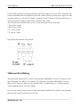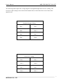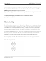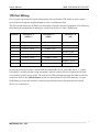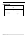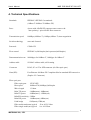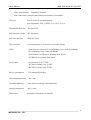
1
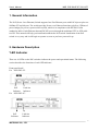
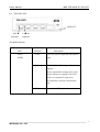
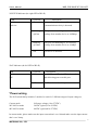
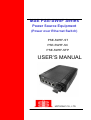
MSE PSE-SW5F Series
Power Source Equipment
(Power over Ethernet Switch)
PSE-SW5F-ST
PSE-SW5F-SC
PSE-SW5F-SFP
USER’S MANUAL
MSTRONIC CO., LTD.
User’s Manual
MSE PSE-SW5F-ST/-SC/-SFP
1. General Information..............................................................
3
2. Hardware Description...........................................................
3
LED Indicators......................................................................................
Power Wiring……………………………………………………………….
Ethernet Port Wiring……………………………………………………….
Fiber Port Wiring...................................................................................
PD Port Wiring…………………………………………………………….
3
5
3.Model Information........................................................
4. Technical Specification........................................................
7
8
9
11
12
2
MSTRONIC CO., LTD.
User’s Manual
MSE PSE-SW5F-ST/-SC/-SFP
1. General Information
The PoE (Power Over Ethernet) Switch supports four Fast Ethernet ports with PoE injector plus one
100Base-FX up-link port. The switch provides Power over Ethernet functions to deliver 35Watts of
power budget per port to a powered device(PD), which is in compliance with IEEE802.3af/at
standard to deliver both Ethernet data and DC48V power through the traditional UTP or STP cable
to a PD. This manual will help you install and maintain the PoE switch. Installation of the PoE
switch is very easy and it will begin to operate as soon as you have powered it up.
2. Hardware Description
*LED Indicator
There are 10 LEDs on the PoE switch to indicate the power and operational status. The following
section describes the functions of each LED indicator.
Front panel detail
For PSE-SW5-ST:
PoE
Indicator
Link/Act
Indicator
For PSE-SW5-SC:
PoE
Link/Act
Indicator
Indicator
3
MSTRONIC CO., LTD.
User’s Manual
MSE PSE-SW5F-ST/-SC/-SFP
For PSE-SW5-SFP:
LINK/ACT
PoE
Link/Act
Indicator
Indicator
*POWER Indicator
LED
Power
STATUS
Green
(PWR)
Description
LED ON if power input has valid power
apply.
Red
LED ON if the following condition
happens.
*Power input under voltage (Vin<10V)
*Power input over voltage (Vin>59V)
*PoE over current(2.5A/per port)
The indicator is used in current mode
only.
Off
No power in DC input
4
MSTRONIC CO., LTD.
User’s Manual
MSE PSE-SW5F-ST/-SC/-SFP
*SWITCH Indicator (the right LED of RJ-45)
LED
P1~P5
STATUS
Green
Link/Act
Description
A network device is detected, but no
communication activity is detected.
Blinking
This port is transmitting to, or receiving
@43ms
package from another device at 100Mbps.
Blinking
This port is transmitting to, or receiving
@120ms
package from another device at 10Mbps.
Off
No device is detected.
*PoE Indicator (the left LED of RJ-45)
LED
STATUS
P1~P4
Yellow
PoE
Description
A valid Powered Device(PD) is detected
and delivering power on this port.
Off
No PD is detected on this port.
*Power wiring
The PoE switch family includes 3 models, be used for 3 different ranges of input voltage as,
Current mode
full range voltage (10 to 57VDC)
24V-802.3at mode
24VDC typical(12 to 36VDC)
48V-802.3at mode
48VDC typical(40 to 57VDC)
In current mode, please make sure the input current don’t over 10Aand make sure the input current
don’t over 2Amp.
5
MSTRONIC CO., LTD.
User’s Manual
MSE PSE-SW5F-ST/-SC/-SFP
For PoE (PSE) operation, the input voltage must be in the range of -42 to -60 VDC. Otherwise, the
switch will function only as an Ethernet switch but will not provide any PoE power output. For PoE
operation, make sure your 48 VDC supply is rated for at least 75 Watts for 4x 802.3af PoE port, or
150W for 4x 802.3at PoE port, plus some overhead for the switch.
The PoE PSE ports will deliver DC power over the spare pairs as the connection:
* TX on lines 1 and 2
* RX on lines 3 and 6
* V+ on line 4 and 5
* V- on line 7 and 8
Rear panel terminal block wiring detail:
*Ethernet Port Wiring
The PoE Switch supports Port 1 to Port 4 with automatic MDI/MDI-X crossover, autosense of the
speed and duplex for 10Base-T or 100Base-TX connections. Automatic MDI/MDI-X crossover
allows you to connect to other devices (switches, hubs, or workstations etc..), without regard to
using straight-through or crossover cabling.
Port 1 to port 4 also provides Power over Ethernet function which delivers DC48V power through
the spare pairs (pair 4,5 and pair7,8) to the PD.
6
MSTRONIC CO., LTD.
User’s Manual
MSE PSE-SW5F-ST/-SC/-SFP
The following tables depict the wiring diagram of straight-through and crossover cabling. The
crossover cables simply cross-connect the transmit lines at each end to the receive lines at the
opposite end.
Straight-through Cabling
Pin 1
Pin 1
Pin2
Pin 2
Pin3
Pin 3
Pin6
Pin6
Cross-over Cabling
Pin 1
Pin 3
Pin 2
Pin 6
Pin 3
Pin 1
Pin 6
Pin 2
7
MSTRONIC CO., LTD.
User’s Manual
MSE PSE-SW5F-ST/-SC/-SFP
Connect an Ethernet cable into any switch port and connect the other side to your attached device.
The green Link/Act LED will light up when the cable is correctly connected. Refer to the LED
indicator section for descriptions of each LED indicator.
If a port LED is off, go back and check for connectivity problems between that port and the network
device it is connected to.
The maximum cable length for 10/100BaseT with Cat 5 twisted pair cables is
typically 100 meters (328 ft.).
Fiber port wiring
The PoE switch(fiber mode) has one 100 Mbps (100Base-FX) multi-mode or single-mode fiber port.
The maximum segment length is dependant upon the type of fiber optic transceiver installed in the
switch. Refer to the technical specifications for details. Or contact a sales agent for the available
fiber optic transceivers(Model NO.:MSE PSE-SW5F-ST or PSE-SW5F-SC or PSE-SW5F-SFP).
The automatic MDI/MDI-X crossover function does not apply to fiber connections. To connect the
fiber optic port on one switch to the fiber optic port of another switch, simply cross-connect the
transmitter at each end to the receiver at the opposite end as illustrated in the figure below.
The corresponding ACT/LNK LED will be ON state when you have made a proper connection.
Fiber cable wiring (SC to SC):
8
MSTRONIC CO., LTD.
User’s Manual
MSE PSE-SW5F-ST/-SC/-SFP
*PD Port Wiring
Port 1 to port 4 provides PoE inject functionality with a maximum 35W ability to power up the
powered device using the straight-through or cross-over Ethernet cable.
The PoE switch follows the IEEE802.3af Alternative B mode connector assignment. The following
table shows pin assignments of alternative A and B for the Power Source Equipment.
Conductor
Alternative A
Alternative A
Alternative B
(MDI-X)
(MDI)
(All)
1
Negative Vport
Positive Vport
2
Negative Vport
Positive Vport
3
Positive Vport
Negative port
4
Positive Vport
5
Positive Vport
6
Positive Vport
Negative Vport
7
Negative Vport
8
Negative Vport
Be sure the twisted pair cable is bound with the standard RJ-45 pin, especially pins 4, 5, 7 and 8.
If the RJ-45 is bound with the wrong pin number, the PoE switch will not recognize the PD and
won’t deliver DC48V power to PD. The yellow PoE LED will light up when the cable is correctly
connected. Refer to the LED Indicator section for descriptions of each LED indicator. If a port
LED flashes, go back and check for connectivity problems between that port and the network
device it is connected to.
9
MSTRONIC CO., LTD.
User’s Manual
MSE PSE-SW5F-ST/-SC/-SFP
3. Model Information
Model
Input Voltage
Output voltage
802.3af/at
PSE-SW5F-ST-S
PSE-SW5F-SC-S
PSE-SW5F-SFP-S
10-57VDC
10-57VDC
(non-regulated)
No
(current mode)
PSE-SW5F-ST24
PSE-SW5F-SC24
PSE-SW5F-SFP24
12-36VDC
56VDC
(regulated)
Yes
(24V-802.3at mode)
PSE-SW5F-ST48
PSE-SW5F-SC48
PSE-SW5F-SFP48
40-57VDC
40-57VDC
(non-regulated)
Yes
(48V-802.3at mode)
10
MSTRONIC CO., LTD.
User’s Manual
MSE PSE-SW5F-ST/-SC/-SFP
4. Technical Specifications
Standards
IEEE802.3/IEEE802.3u standards
(10Base-T/100Base-T/100Base-FX)
Ports
4 ports with 4 PoE(PSE), supports auto-crossover &
auto-polarity, 1 port with the fiber connector
Transmission speed
100Mbps(100Base-T), 10Mbps(10Base-T) Auto-negotiation
Switch technology
store-and-forward
Protocols
CSMA/CD
Flow control
IEEE802.3x(full-duplex),back pressure(half-duplex)
Data transmission rate
148800pps for 100Base-T, 14880pps for 10Base-T
Address table
1K MAC address table, self-learning
Connector
RJ-45, SC or ST or SFP connector (for fiber optic port)
Note(SFP):
Fast Ethernet 100 Base-FX Complaint Slot for standard SFP transceiver
(Duplex LC Connector)
Fiber optic port
*Fiber optic port:
*Port speed
*Wave length
ST/SC/SFP
100Base-FX(100Mbps),full duplex
1310nm
*Max TX power
-14dBm(mm), -8dBm(sm)
*Min TX power
-19dBm(mm), -15dBm(sm)
*Min RX sensitivity -32dBm
*Max RX power
-14dBm(mm),-8dBm(sm)
*Link budge
13dB(mm),17dB(sm)
*Fiber multi-mode(mm) typical
50 or 62.5/125um
*Fiber single-mode(sm) typical
9 or 10/125um
11
MSTRONIC CO., LTD.
User’s Manual
MSE PSE-SW5F-ST/-SC/-SFP
*Fiber max. distance 2km(mm),15km(sm)
Note: Other fiber connector and transmission distance are available.
PoE port
Port 1-4, auto power management
Pin assignment: TX(1,2), RX(3,6), V+(4,5), V-(7,8)
Maximum PoE power
Per port 35W
PoE disconnect mode
DC disconnect
PoE auto detection
IEEE802.3af/at
PoE protection
Over-temperature, over-current, over/under voltage
LEDs
*Link/Activity (Green ON/ Green Blinking every 43ms @100Mbps/
Green Blinking every 120ms @10Mbps)
*PoE(Yellow) On-PD detect, Blinking-error detect)
*POWER Green-normal, Red-alarm
Power input
Current mode:10 to 57VDC
24V-802.3at mode:12 to 36VDC
48V-802.3at mode:40 to 57VDC
Power consumption
5W without PD loading
Operating temperature
-20℃~ 85℃
Operation humidity
90% relative humidity, non-condensing
Storage temperature
-55℃~+105℃
Dimension
40mm(H)x118mm(W)x159mm(D)
12
MSTRONIC CO., LTD.