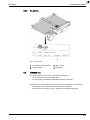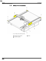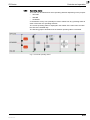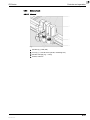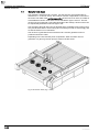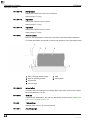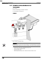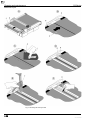
1
Digital flatbed cutter G3 series (M-1600, M-2500, L-2500, L-3200, XL-1600, XL-3200, 2XL-1600, 2XL-3200, 3XL-1600, 3XL-3200) Operating manual EN Translation of the original operating instructions Author Technicak Editorial Department, Zünd Systemtechnik AG Composition and publication Zünd Systemtechnik AG Copyright © Zünd Systemtechnik AG Version: 04 Menu version: 1.40 Date: 02-2009 Doc. no.: 5106015 0 G3 Series Contents 1 1.1 1.2 1.2.1 1.2.2 1.3 1.4 1.5 1.6 1.6.1 1.6.2 1.6.3 1.7 1.8 1.9 1.10 Introduction . . . . . . . . . . . . . . . . . . . . . . . . . . . . . . . . . . . . . . . . . . . . . . . . .1 Foreword . . . . . . . . . . . . . . . . . . . . . . . . . . . . . . . . . . . . . . . . . . . . . . . . . . . 1 Using the documentation . . . . . . . . . . . . . . . . . . . . . . . . . . . . . . . . . . . . . . 2 Structure of the operating manual . . . . . . . . . . . . . . . . . . . . . . . . . . . . . . . 2 Symbols . . . . . . . . . . . . . . . . . . . . . . . . . . . . . . . . . . . . . . . . . . . . . . . . . . . 3 Points to note when reading this operating manual . . . . . . . . . . . . . . . . . . 4 Care of the documentation . . . . . . . . . . . . . . . . . . . . . . . . . . . . . . . . . . . . . 4 Current status of documentation . . . . . . . . . . . . . . . . . . . . . . . . . . . . . . . . . 5 Standardisation, tests, marking . . . . . . . . . . . . . . . . . . . . . . . . . . . . . . . . . 5 Standards . . . . . . . . . . . . . . . . . . . . . . . . . . . . . . . . . . . . . . . . . . . . . . . . . . 5 CE marking . . . . . . . . . . . . . . . . . . . . . . . . . . . . . . . . . . . . . . . . . . . . . . . . . 5 UL testing . . . . . . . . . . . . . . . . . . . . . . . . . . . . . . . . . . . . . . . . . . . . . . . . . . 6 Legal notice . . . . . . . . . . . . . . . . . . . . . . . . . . . . . . . . . . . . . . . . . . . . . . . . 7 Troubleshooting, hints and tips . . . . . . . . . . . . . . . . . . . . . . . . . . . . . . . . . . 7 Documented cutter models . . . . . . . . . . . . . . . . . . . . . . . . . . . . . . . . . . . . . 7 Publishing details . . . . . . . . . . . . . . . . . . . . . . . . . . . . . . . . . . . . . . . . . . . . 7 2 2.1 2.2 2.2.1 2.2.2 2.3 2.4 2.5 2.5.1 2.5.2 2.5.2.1 2.5.3 2.5.4 2.6 2.6.1 2.6.2 2.6.3 2.6.4 2.6.5 2.7 2.7.1 2.7.2 2.7.3 2.7.4 2.7.5 2.8 2.8.1 2.8.1.1 2.8.1.2 2.8.2 2.8.3 2.8.4 Product description . . . . . . . . . . . . . . . . . . . . . . . . . . . . . . . . . . . . . . . . . . .1 General . . . . . . . . . . . . . . . . . . . . . . . . . . . . . . . . . . . . . . . . . . . . . . . . . . . . 1 Product identification . . . . . . . . . . . . . . . . . . . . . . . . . . . . . . . . . . . . . . . . . 2 Rating plate . . . . . . . . . . . . . . . . . . . . . . . . . . . . . . . . . . . . . . . . . . . . . . . . . 2 UL marking . . . . . . . . . . . . . . . . . . . . . . . . . . . . . . . . . . . . . . . . . . . . . . . . . 3 Intended use . . . . . . . . . . . . . . . . . . . . . . . . . . . . . . . . . . . . . . . . . . . . . . . . 3 Cutter - overview . . . . . . . . . . . . . . . . . . . . . . . . . . . . . . . . . . . . . . . . . . . . . 4 Modules, tools . . . . . . . . . . . . . . . . . . . . . . . . . . . . . . . . . . . . . . . . . . . . . . . 5 General . . . . . . . . . . . . . . . . . . . . . . . . . . . . . . . . . . . . . . . . . . . . . . . . . . . . 5 UM . . . . . . . . . . . . . . . . . . . . . . . . . . . . . . . . . . . . . . . . . . . . . . . . . . . . . . . 5 Tools for the UM . . . . . . . . . . . . . . . . . . . . . . . . . . . . . . . . . . . . . . . . . . . . . 6 RM-A . . . . . . . . . . . . . . . . . . . . . . . . . . . . . . . . . . . . . . . . . . . . . . . . . . . . . . 7 PUM . . . . . . . . . . . . . . . . . . . . . . . . . . . . . . . . . . . . . . . . . . . . . . . . . . . . . . 7 Material handling, options . . . . . . . . . . . . . . . . . . . . . . . . . . . . . . . . . . . . . . 8 Laser pointer settings . . . . . . . . . . . . . . . . . . . . . . . . . . . . . . . . . . . . . . . . . 8 ICC camera . . . . . . . . . . . . . . . . . . . . . . . . . . . . . . . . . . . . . . . . . . . . . . . . . 8 Cutter with static work surface . . . . . . . . . . . . . . . . . . . . . . . . . . . . . . . . . . 8 Cutter with conveyor . . . . . . . . . . . . . . . . . . . . . . . . . . . . . . . . . . . . . . . . . . 9 Sheet feeder options . . . . . . . . . . . . . . . . . . . . . . . . . . . . . . . . . . . . . . . . . . 9 Technical description . . . . . . . . . . . . . . . . . . . . . . . . . . . . . . . . . . . . . . . . 10 Complete machine . . . . . . . . . . . . . . . . . . . . . . . . . . . . . . . . . . . . . . . . . . 10 Schedule of work sequences . . . . . . . . . . . . . . . . . . . . . . . . . . . . . . . . . . 10 Complete machine . . . . . . . . . . . . . . . . . . . . . . . . . . . . . . . . . . . . . . . . . . 11 Movement system . . . . . . . . . . . . . . . . . . . . . . . . . . . . . . . . . . . . . . . . . . . 12 Processing materials . . . . . . . . . . . . . . . . . . . . . . . . . . . . . . . . . . . . . . . . 13 Technical information . . . . . . . . . . . . . . . . . . . . . . . . . . . . . . . . . . . . . . . . 14 Dimensions and weights . . . . . . . . . . . . . . . . . . . . . . . . . . . . . . . . . . . . . . 14 Basic device . . . . . . . . . . . . . . . . . . . . . . . . . . . . . . . . . . . . . . . . . . . . . . . 14 Cutter extension . . . . . . . . . . . . . . . . . . . . . . . . . . . . . . . . . . . . . . . . . . . . 16 Electrical connection, power consumption . . . . . . . . . . . . . . . . . . . . . . . . 17 Environmental conditions . . . . . . . . . . . . . . . . . . . . . . . . . . . . . . . . . . . . . 17 Basic device compressed air . . . . . . . . . . . . . . . . . . . . . . . . . . . . . . . . . . 17 0-1 000017,02,12-2008, jmu 0 G3 Series 2.8.5 2.8.6 2.8.7 2.8.8 Control unit . . . . . . . . . . . . . . . . . . . . . . . . . . . . . . . . . . . . . . . . . . . . . . . . 18 Performance . . . . . . . . . . . . . . . . . . . . . . . . . . . . . . . . . . . . . . . . . . . . . . . 19 Emissions . . . . . . . . . . . . . . . . . . . . . . . . . . . . . . . . . . . . . . . . . . . . . . . . . 20 FCC approval . . . . . . . . . . . . . . . . . . . . . . . . . . . . . . . . . . . . . . . . . . . . . . 20 3 3.1 3.2 3.3 3.4 3.4.1 3.4.2 3.5 3.6 3.7 3.8 3.9 3.9.1 3.9.2 3.9.3 3.10 3.11 3.11.1 3.11.2 3.12 3.12.1 3.12.2 3.12.3 3.12.4 3.13 3.14 3.14.1 3.14.2 3.14.3 3.15 3.16 3.17 3.18 3.19 3.20 3.21 3.22 3.23 3.24 3.25 Safety . . . . . . . . . . . . . . . . . . . . . . . . . . . . . . . . . . . . . . . . . . . . . . . . . . . . .1 General . . . . . . . . . . . . . . . . . . . . . . . . . . . . . . . . . . . . . . . . . . . . . . . . . . . . 1 Proper use . . . . . . . . . . . . . . . . . . . . . . . . . . . . . . . . . . . . . . . . . . . . . . . . . 2 Examples of improper use . . . . . . . . . . . . . . . . . . . . . . . . . . . . . . . . . . . . . 2 Hazard warnings, important instructions . . . . . . . . . . . . . . . . . . . . . . . . . . . 3 Explanation of the hazard warning . . . . . . . . . . . . . . . . . . . . . . . . . . . . . . . 3 Structure of the hazard warnings . . . . . . . . . . . . . . . . . . . . . . . . . . . . . . . . 4 Areas of responsibility . . . . . . . . . . . . . . . . . . . . . . . . . . . . . . . . . . . . . . . . . 5 Personnel requirements . . . . . . . . . . . . . . . . . . . . . . . . . . . . . . . . . . . . . . . 5 Rules and safety at work . . . . . . . . . . . . . . . . . . . . . . . . . . . . . . . . . . . . . . . 6 Procedure in case of malfunctions . . . . . . . . . . . . . . . . . . . . . . . . . . . . . . . 6 Danger areas . . . . . . . . . . . . . . . . . . . . . . . . . . . . . . . . . . . . . . . . . . . . . . . 7 General danger area . . . . . . . . . . . . . . . . . . . . . . . . . . . . . . . . . . . . . . . . . . 7 Danger area on the module carriage . . . . . . . . . . . . . . . . . . . . . . . . . . . . . 8 Danger area during the installation . . . . . . . . . . . . . . . . . . . . . . . . . . . . . . . 9 Working and traffic area . . . . . . . . . . . . . . . . . . . . . . . . . . . . . . . . . . . . . . 10 Safety signs . . . . . . . . . . . . . . . . . . . . . . . . . . . . . . . . . . . . . . . . . . . . . . . 11 Responsibility of the operator . . . . . . . . . . . . . . . . . . . . . . . . . . . . . . . . . . 11 Position of the safety signs . . . . . . . . . . . . . . . . . . . . . . . . . . . . . . . . . . . . 11 Safety and monitoring devices . . . . . . . . . . . . . . . . . . . . . . . . . . . . . . . . . 14 Protective system . . . . . . . . . . . . . . . . . . . . . . . . . . . . . . . . . . . . . . . . . . . 15 Panel . . . . . . . . . . . . . . . . . . . . . . . . . . . . . . . . . . . . . . . . . . . . . . . . . . . . . 15 Emergency stop switch . . . . . . . . . . . . . . . . . . . . . . . . . . . . . . . . . . . . . . . 16 Safety cut-off feature . . . . . . . . . . . . . . . . . . . . . . . . . . . . . . . . . . . . . . . . . 16 Personal protective equipment, clothing . . . . . . . . . . . . . . . . . . . . . . . . . . 17 Mechanical hazards . . . . . . . . . . . . . . . . . . . . . . . . . . . . . . . . . . . . . . . . . 18 Gathering, retraction . . . . . . . . . . . . . . . . . . . . . . . . . . . . . . . . . . . . . . . . . 18 Gathering, impacts of foreign objects . . . . . . . . . . . . . . . . . . . . . . . . . . . . 18 Cuts and stab wounds . . . . . . . . . . . . . . . . . . . . . . . . . . . . . . . . . . . . . . . 19 Risk of burns . . . . . . . . . . . . . . . . . . . . . . . . . . . . . . . . . . . . . . . . . . . . . . . 19 Electrical hazard . . . . . . . . . . . . . . . . . . . . . . . . . . . . . . . . . . . . . . . . . . . . 20 Risks arising from the emission of toxic dust . . . . . . . . . . . . . . . . . . . . . . 21 Risks arising from the processing of toxic/hazardous materials . . . . . . . . 21 Environmental hazard . . . . . . . . . . . . . . . . . . . . . . . . . . . . . . . . . . . . . . . . 22 Handling and storage of chemicals . . . . . . . . . . . . . . . . . . . . . . . . . . . . . . 23 Risk of fire and explosion . . . . . . . . . . . . . . . . . . . . . . . . . . . . . . . . . . . . . 24 Danger caused by laser beam (laser pointer) . . . . . . . . . . . . . . . . . . . . . . 25 Safety instructions for operators . . . . . . . . . . . . . . . . . . . . . . . . . . . . . . . . 25 Safety precautions for service personnel . . . . . . . . . . . . . . . . . . . . . . . . . 26 Disposal . . . . . . . . . . . . . . . . . . . . . . . . . . . . . . . . . . . . . . . . . . . . . . . . . . 26 0-2 000017,02,12-2008, jmu 0 G3 Series 4 4.1 4.2 4.3 4.3.1 4.3.1.1 4.3.1.2 4.3.1.3 4.3.1.4 4.3.1.5 4.3.1.6 4.3.1.7 4.3.2 4.3.3 4.3.4 4.4 4.4.1 4.4.2 4.4.3 4.4.4 4.4.5 4.4.6 4.5 4.5.1 4.5.2 4.5.3 4.5.4 4.6 4.6.1 4.6.2 4.6.3 4.6.3.1 4.6.3.2 4.6.3.3 4.6.4 4.6.5 4.6.6 4.6.6.1 4.6.6.2 4.6.6.3 4.6.7 4.6.7.1 4.6.7.2 4.6.8 4.6.9 4.7 4.7.1 4.7.2 4.7.3 4.7.4 Controls and operation . . . . . . . . . . . . . . . . . . . . . . . . . . . . . . . . . . . . . . . .1 General . . . . . . . . . . . . . . . . . . . . . . . . . . . . . . . . . . . . . . . . . . . . . . . . . . . . 1 Safe working practices . . . . . . . . . . . . . . . . . . . . . . . . . . . . . . . . . . . . . . . . 1 Controls . . . . . . . . . . . . . . . . . . . . . . . . . . . . . . . . . . . . . . . . . . . . . . . . . . . 2 Control panel . . . . . . . . . . . . . . . . . . . . . . . . . . . . . . . . . . . . . . . . . . . . . . . 2 Operating unit . . . . . . . . . . . . . . . . . . . . . . . . . . . . . . . . . . . . . . . . . . . . . . . 3 Navigation keys . . . . . . . . . . . . . . . . . . . . . . . . . . . . . . . . . . . . . . . . . . . . . 4 Numerical keys . . . . . . . . . . . . . . . . . . . . . . . . . . . . . . . . . . . . . . . . . . . . . . 5 Function keys . . . . . . . . . . . . . . . . . . . . . . . . . . . . . . . . . . . . . . . . . . . . . . . 6 Travel keys . . . . . . . . . . . . . . . . . . . . . . . . . . . . . . . . . . . . . . . . . . . . . . . . . 7 Soft keys . . . . . . . . . . . . . . . . . . . . . . . . . . . . . . . . . . . . . . . . . . . . . . . . . . . 8 Special keys, shortcuts . . . . . . . . . . . . . . . . . . . . . . . . . . . . . . . . . . . . . . . . 9 Emergency stop switch . . . . . . . . . . . . . . . . . . . . . . . . . . . . . . . . . . . . . . . 10 Maintenance unit . . . . . . . . . . . . . . . . . . . . . . . . . . . . . . . . . . . . . . . . . . . 12 Interfaces . . . . . . . . . . . . . . . . . . . . . . . . . . . . . . . . . . . . . . . . . . . . . . . . . 13 Menu navigation . . . . . . . . . . . . . . . . . . . . . . . . . . . . . . . . . . . . . . . . . . . . 14 Menus and functions . . . . . . . . . . . . . . . . . . . . . . . . . . . . . . . . . . . . . . . . . 14 Help . . . . . . . . . . . . . . . . . . . . . . . . . . . . . . . . . . . . . . . . . . . . . . . . . . . . . 16 Info Menu . . . . . . . . . . . . . . . . . . . . . . . . . . . . . . . . . . . . . . . . . . . . . . . . . 16 Popups/dialogues . . . . . . . . . . . . . . . . . . . . . . . . . . . . . . . . . . . . . . . . . . . 16 User level . . . . . . . . . . . . . . . . . . . . . . . . . . . . . . . . . . . . . . . . . . . . . . . . . 17 Function keys . . . . . . . . . . . . . . . . . . . . . . . . . . . . . . . . . . . . . . . . . . . . . . 18 Functions . . . . . . . . . . . . . . . . . . . . . . . . . . . . . . . . . . . . . . . . . . . . . . . . . 19 Set language . . . . . . . . . . . . . . . . . . . . . . . . . . . . . . . . . . . . . . . . . . . . . . . 19 Set display . . . . . . . . . . . . . . . . . . . . . . . . . . . . . . . . . . . . . . . . . . . . . . . . 19 Setting the volume of the signal . . . . . . . . . . . . . . . . . . . . . . . . . . . . . . . . 19 Delete data buffer . . . . . . . . . . . . . . . . . . . . . . . . . . . . . . . . . . . . . . . . . . . 19 Operation . . . . . . . . . . . . . . . . . . . . . . . . . . . . . . . . . . . . . . . . . . . . . . . . . 20 Daily checks prior to start-up . . . . . . . . . . . . . . . . . . . . . . . . . . . . . . . . . . 20 Start-up . . . . . . . . . . . . . . . . . . . . . . . . . . . . . . . . . . . . . . . . . . . . . . . . . . . 21 Operating status . . . . . . . . . . . . . . . . . . . . . . . . . . . . . . . . . . . . . . . . . . . . 23 OFFLINE . . . . . . . . . . . . . . . . . . . . . . . . . . . . . . . . . . . . . . . . . . . . . . . . . . 24 STOPPED . . . . . . . . . . . . . . . . . . . . . . . . . . . . . . . . . . . . . . . . . . . . . . . . . 25 ONLINE . . . . . . . . . . . . . . . . . . . . . . . . . . . . . . . . . . . . . . . . . . . . . . . . . . 26 Moving the bar/module manually . . . . . . . . . . . . . . . . . . . . . . . . . . . . . . . 27 Tool handling . . . . . . . . . . . . . . . . . . . . . . . . . . . . . . . . . . . . . . . . . . . . . . 28 Modules/tools . . . . . . . . . . . . . . . . . . . . . . . . . . . . . . . . . . . . . . . . . . . . . . 31 General . . . . . . . . . . . . . . . . . . . . . . . . . . . . . . . . . . . . . . . . . . . . . . . . . . . 31 Inserting/replacing the module . . . . . . . . . . . . . . . . . . . . . . . . . . . . . . . . . 32 Tool (e.g. oscillating tool) . . . . . . . . . . . . . . . . . . . . . . . . . . . . . . . . . . . . . 34 Connecting driven tools - allocating port . . . . . . . . . . . . . . . . . . . . . . . . . . 35 Connection - electrical tools (EOT, DRT, etc.) . . . . . . . . . . . . . . . . . . . . . 36 Connect pneumatically driven tools . . . . . . . . . . . . . . . . . . . . . . . . . . . . . 37 Activating the module . . . . . . . . . . . . . . . . . . . . . . . . . . . . . . . . . . . . . . . . 38 Tool positions . . . . . . . . . . . . . . . . . . . . . . . . . . . . . . . . . . . . . . . . . . . . . . 39 Material hold-down . . . . . . . . . . . . . . . . . . . . . . . . . . . . . . . . . . . . . . . . . . 40 Preparation . . . . . . . . . . . . . . . . . . . . . . . . . . . . . . . . . . . . . . . . . . . . . . . . 41 Defining/checking the vacuum range . . . . . . . . . . . . . . . . . . . . . . . . . . . . 42 Setting the strength . . . . . . . . . . . . . . . . . . . . . . . . . . . . . . . . . . . . . . . . . . 43 Switching on/off . . . . . . . . . . . . . . . . . . . . . . . . . . . . . . . . . . . . . . . . . . . . 43 0-3 000017,02,12-2008, jmu 0 G3 Series 4.8 4.8.1 4.8.2 4.8.3 4.9 4.9.1 4.9.2 4.9.3 4.10 4.10.1 4.10.2 4.10.3 4.10.4 4.11 4.12 4.13 Feeding options* . . . . . . . . . . . . . . . . . . . . . . . . . . . . . . . . . . . . . . . . . . . . 44 Feeding clamps . . . . . . . . . . . . . . . . . . . . . . . . . . . . . . . . . . . . . . . . . . . . . 45 Feed guide rail . . . . . . . . . . . . . . . . . . . . . . . . . . . . . . . . . . . . . . . . . . . . . 46 Feeding options . . . . . . . . . . . . . . . . . . . . . . . . . . . . . . . . . . . . . . . . . . . . 47 Automatic tool initialisation . . . . . . . . . . . . . . . . . . . . . . . . . . . . . . . . . . . . 48 Description . . . . . . . . . . . . . . . . . . . . . . . . . . . . . . . . . . . . . . . . . . . . . . . . 48 Setting the height . . . . . . . . . . . . . . . . . . . . . . . . . . . . . . . . . . . . . . . . . . . 49 Initialisation . . . . . . . . . . . . . . . . . . . . . . . . . . . . . . . . . . . . . . . . . . . . . . . . 50 Laser pointer, reference point . . . . . . . . . . . . . . . . . . . . . . . . . . . . . . . . . . 51 Laser pointer settings . . . . . . . . . . . . . . . . . . . . . . . . . . . . . . . . . . . . . . . . 51 Reference point settings . . . . . . . . . . . . . . . . . . . . . . . . . . . . . . . . . . . . . . 52 Choose laser pointer as pointer type . . . . . . . . . . . . . . . . . . . . . . . . . . . . 53 Define reference point . . . . . . . . . . . . . . . . . . . . . . . . . . . . . . . . . . . . . . . . 53 Module carriage slot protective plate . . . . . . . . . . . . . . . . . . . . . . . . . . . . 54 Module and tool holder* . . . . . . . . . . . . . . . . . . . . . . . . . . . . . . . . . . . . . . 55 Switch off the machine . . . . . . . . . . . . . . . . . . . . . . . . . . . . . . . . . . . . . . . 56 5 5.1 5.2 5.3 Description of menu . . . . . . . . . . . . . . . . . . . . . . . . . . . . . . . . . . . . . . . . . .1 General . . . . . . . . . . . . . . . . . . . . . . . . . . . . . . . . . . . . . . . . . . . . . . . . . . . . 1 Menu structure . . . . . . . . . . . . . . . . . . . . . . . . . . . . . . . . . . . . . . . . . . . . . . 1 Description of menu . . . . . . . . . . . . . . . . . . . . . . . . . . . . . . . . . . . . . . . . . . 2 6 6.1 6.2 6.2.1 6.2.2 6.3 Malfunctions . . . . . . . . . . . . . . . . . . . . . . . . . . . . . . . . . . . . . . . . . . . . . . . .1 Troubleshooting . . . . . . . . . . . . . . . . . . . . . . . . . . . . . . . . . . . . . . . . . . . . . 1 Locate error . . . . . . . . . . . . . . . . . . . . . . . . . . . . . . . . . . . . . . . . . . . . . . . . . 1 Error display . . . . . . . . . . . . . . . . . . . . . . . . . . . . . . . . . . . . . . . . . . . . . . . . 2 Error code . . . . . . . . . . . . . . . . . . . . . . . . . . . . . . . . . . . . . . . . . . . . . . . . . . 3 Error messages . . . . . . . . . . . . . . . . . . . . . . . . . . . . . . . . . . . . . . . . . . . . . . 4 7 7.1 7.2 7.3 7.3.1 7.3.2 7.3.3 7.3.4 7.4 7.5 7.6 7.7 7.7.1 7.7.2 7.7.3 7.7.4 7.7.5 7.7.6 7.7.7 7.7.8 7.7.9 7.7.10 Cleaning and maintenance . . . . . . . . . . . . . . . . . . . . . . . . . . . . . . . . . . . . .1 General . . . . . . . . . . . . . . . . . . . . . . . . . . . . . . . . . . . . . . . . . . . . . . . . . . . . 1 Safe maintenance of the machine . . . . . . . . . . . . . . . . . . . . . . . . . . . . . . . 2 Operating resources . . . . . . . . . . . . . . . . . . . . . . . . . . . . . . . . . . . . . . . . . . 3 Handling operating materials . . . . . . . . . . . . . . . . . . . . . . . . . . . . . . . . . . . 3 Cleaning fluids . . . . . . . . . . . . . . . . . . . . . . . . . . . . . . . . . . . . . . . . . . . . . . 4 Lubricants . . . . . . . . . . . . . . . . . . . . . . . . . . . . . . . . . . . . . . . . . . . . . . . . . . 4 Adhesives . . . . . . . . . . . . . . . . . . . . . . . . . . . . . . . . . . . . . . . . . . . . . . . . . . 4 Steps for maintenance . . . . . . . . . . . . . . . . . . . . . . . . . . . . . . . . . . . . . . . . 5 Lubrication diagram . . . . . . . . . . . . . . . . . . . . . . . . . . . . . . . . . . . . . . . . . . 8 Accessories case . . . . . . . . . . . . . . . . . . . . . . . . . . . . . . . . . . . . . . . . . . . . 8 Maintenance jobs . . . . . . . . . . . . . . . . . . . . . . . . . . . . . . . . . . . . . . . . . . . 10 Service flaps and covers . . . . . . . . . . . . . . . . . . . . . . . . . . . . . . . . . . . . . . 10 Maintenance position . . . . . . . . . . . . . . . . . . . . . . . . . . . . . . . . . . . . . . . . 11 Visually inspect the machine for damage . . . . . . . . . . . . . . . . . . . . . . . . . 11 Clean the machine . . . . . . . . . . . . . . . . . . . . . . . . . . . . . . . . . . . . . . . . . . 12 Clean X axis guide rails . . . . . . . . . . . . . . . . . . . . . . . . . . . . . . . . . . . . . . 13 Oil X axis guide bearings . . . . . . . . . . . . . . . . . . . . . . . . . . . . . . . . . . . . . 15 Cleaning/oiling Y axis guide rails . . . . . . . . . . . . . . . . . . . . . . . . . . . . . . . 19 Lubricating the Y axis bearing . . . . . . . . . . . . . . . . . . . . . . . . . . . . . . . . . . 21 Clean the chipping protection brush . . . . . . . . . . . . . . . . . . . . . . . . . . . . . 22 Cleaning the feeding clamps/feed guide rail . . . . . . . . . . . . . . . . . . . . . . . 23 0-4 000017,02,12-2008, jmu 0 G3 Series 7.7.11 Draining the maintenance unit condensation water . . . . . . . . . . . . . . . . . 24 7.7.12 Automatic circuit breakers . . . . . . . . . . . . . . . . . . . . . . . . . . . . . . . . . . . . 25 7.7.13 Conveyor belt . . . . . . . . . . . . . . . . . . . . . . . . . . . . . . . . . . . . . . . . . . . . . . 27 7.7.13.1Removing the conveyor belt . . . . . . . . . . . . . . . . . . . . . . . . . . . . . . . . . . . 27 7.7.13.2Remove the covers . . . . . . . . . . . . . . . . . . . . . . . . . . . . . . . . . . . . . . . . . 28 7.7.13.3Fitting a conveyor belt . . . . . . . . . . . . . . . . . . . . . . . . . . . . . . . . . . . . . . . 29 7.8 Instructions for disposal . . . . . . . . . . . . . . . . . . . . . . . . . . . . . . . . . . . . . . 35 7.9 Starting up after periods at a standstill . . . . . . . . . . . . . . . . . . . . . . . . . . . 35 7.9.1 Vacuum generator 1-9 KW/1-15 KW . . . . . . . . . . . . . . . . . . . . . . . . . . . . 35 8 Tools . . . . . . . . . . . . . . . . . . . . . . . . . . . . . . . . . . . . . . . . . . . . . . . . . . . . . .1 9 Modules . . . . . . . . . . . . . . . . . . . . . . . . . . . . . . . . . . . . . . . . . . . . . . . . . . . .1 10 Options . . . . . . . . . . . . . . . . . . . . . . . . . . . . . . . . . . . . . . . . . . . . . . . . . . . .1 11 Material handling . . . . . . . . . . . . . . . . . . . . . . . . . . . . . . . . . . . . . . . . . . . . .1 12 Additional specifications . . . . . . . . . . . . . . . . . . . . . . . . . . . . . . . . . . . . . . .1 13 Documents . . . . . . . . . . . . . . . . . . . . . . . . . . . . . . . . . . . . . . . . . . . . . . . . .1 14 Glossary . . . . . . . . . . . . . . . . . . . . . . . . . . . . . . . . . . . . . . . . . . . . . . . . . . .1 0-5 000017,02,12-2008, jmu 0 G3 Series 0-6 000017,02,12-2008, jmu 1 G3 Series Introduction Foreword 1 Introduction Zünd Systemtechnik AG Altstätten, Switzerland 1.1 Foreword Dear customer, By purchasing our product you are participating in the worldwide success of Zünd cutter systems. The modular design of our systems ensures: • A system solution that is suited to your individual requirements in terms of speed and quality • The availability of the most up-to-date technology thanks to constant developments Our approach Constant and intensive cooperation with successful users is a prerequisite for innovative and practical solutions. We are therefore grateful for any comments or suggestions on how we can improve. Contact Zünd Systemtechnik AG Industriestrasse 8 CH - 9450 Altstätten Tel. ++41 71-757 8181 Fax ++41 71-757 8191 Email [email protected] www zund.com 1-1 000009,04,02-2009, jmu 1 Introduction G3 Series Using the documentation 1.2 Using the documentation The instruction handbook supplied is intended to help you to: – Operate the machine safely – Perform routine machine maintenance – Use the machine optimally in all permitted areas To do this, you need to be able to find what you want within the documentation. The instruction handbook comprises: Volume 1 - Operating manual This volume contains information on the engineering, installation, operation and maintenance of the basic machine. The technical documentation for the service personnel is contained in volumes 2 and 3: Volume 2 - Service manual * This volume contains information on the structure of the machine and on servicing by authorised service personnel Volume 3 - Spare parts catalogue * (See Zünd homepage) 1.2.1 Structure of the operating manual The operating manual consists of individual, consecutively numbered chapters. These sections are arranged according to the ring binder tabs. The table of contents provides information on the structure of the individual chapters. The numbers of pages and certain large graphics are prefixed with the number of the relevant chapter. Page number "2-10", for example, means the tenth page of chapter 2 "Product description". 1-2 000009,04,02-2009, jmu 1 G3 Series Introduction Using the documentation 1.2.2 Symbols Illustration Close, fix, tighten, in Open, release, loosen, out Higher Lower Text structuring Task: Steps to perform Result: Outcome of the tasks performed. Prerequisites for performing a task List of tools Optional accessories There are a number of optional accessories available for the machine. Any description relating to an optional accessory is identified in the operating manual by the * symbol. 1-3 000009,04,02-2009, jmu 1 Introduction Points to note when reading this operating manual 1.3 G3 Series Points to note when reading this operating manual Text references Chapter headings are numbered consecutively, with the first figure corresponding to the chapter number. Where reference is made to sections outside the current chapter, note the first figure and turn to the corresponding chapter, which contains the cited section. See chapter 2-4 "Overview of the machine", for example, leads to chapter 2 "Product description", which contains section 4 "Overview of the machine". Sketches and schematic representations These are provided for general information and do not necessarily correspond to the latest version of the machine. Dimensional information Dimensional information is listed in the SI/US unit system according to the place of installation. 1.4 Care of the documentation Volume 1 "Instruction manual" must always be kept in close vicinity of the workstation. Volume 2 "Service manual" must be made available to maintenance and service personnel when required. 1-4 000009,04,02-2009, jmu 1 G3 Series Introduction Current status of documentation 1.5 Current status of documentation Act accordingly to make sure that the documentation is complete and up-to-date at all times: – Do not remove parts of the documentation – Request copies of missing or illegible pages from the manufacturer, or download and print them from the Zünd homepage – If any new documentation is delivered as a result of conversions taking place, file it away immediately – If documentation is changed, file the new information and destroy the old – If the documentation exists in more than one language, ensure that all languages are kept up-to-date 1.6 Standardisation, tests, marking 1.6.1 Standards Scope of the documentation supplied Volume 1: Operating manual Volume 2: Service manual * Volume 3: Spare parts catalogue * Execution This operating manual makes reference to the following standards: • EN 62079 • EN 62023 • ANSI Z535-6 • EN ISO 12100-2 Important ! EU standards and guidelines which are applied are listed in the declaration of conformity. In the interests of our customers, we reserve the right to make changes as a result of technical improvements. This document therefore corresponds to the technical status of the product supplied and not the manufacturer's current state of development. 1.6.2 CE marking Within the EU, the cutter system is delivered with CE marking and an EC declaration of conformity according to Annex II A of the EC Machinery Directive 2006/42/EC (see chapter "Documents") Important ! If the purchaser adds additional devices to the cutter system, or if the system is integrated into an larger system then the device is supplied with a "Declaration for the installation of an incomplete machine" according to Appendix II A of the EU 1-5 000009,04,02-2009, jmu 1 Introduction G3 Series Standardisation, tests, marking Machinery Directive 2006/42/EC and/or without CE marking. As a result, the declaration of conformity must be issued again by the purchaser. 1.6.3 UL testing Zünd G3 cutters have been UL tested and comply with the ISO 60950 standard. The certification can be accessed under UL number E176661. 1-6 000009,04,02-2009, jmu 1 G3 Series Introduction Legal notice 1.7 Legal notice The information contained in this publication is intended for information purposes only and is subject to change without notice at any time. This does not constitute an obligation on the part of Zünd Systemtechnik AG. No part of this document may be copied, distributed, used or disclosed to third parties without express permission. Offenders will be liable for damages. 1.8 Troubleshooting, hints and tips Important ! You can find information about troubleshooting and useful hints and tips on the Zünd homepage. (www.zund.com) 1.9 Documented cutter models This documentation applies for the following types of G3 series cutters. G3 Series M line L line XL line 2XL line 3XL line M-1600 L-3200 XL-3200 2XL-3200 3XL-3200 M-2500 L-2500 XL-2500 2XL-1600 3XL-1600 XL-1600 1.10 Publishing details Name Operating manual for G3 series cutters, side-support version. Composition, illustration and publication Zünd Systemtechnik AG - Technical Editorial Department ©Copyright Zünd Systemtechnik AG 1-7 000009,04,02-2009, jmu 1 Introduction Publishing details G3 Series 1-8 000009,04,02-2009, jmu 2 G3 Series Product description General 2 2.1 Product description General This chapter contains information on the following: – Representational conventions in the operating manual – Possible uses of the machine – Structure of the main components – Important technical data – General technical description of the device Directional information Directions such as "right, left" or "forwards, backwards" are specified according to the operator's view of the machine during operation. Fig. 2-1 Directional information 1 Front 3 Left 2 Back 4 Right Y Y axis X X axis Important information Important ! Refers to user tips and useful information which enhance the usability and prolong the service life of the machine and make the work significantly easier. 2-1 000003,04,02-2009, jmu 2 Product description G3 Series Product identification 2.2 Product identification 2.2.1 Rating plate Important ! The rating plate is used to uniquely identify your machine. Fig. 2-2 Position of rating plate 1 Manufacturer 5 Year of manufacture 2 Product category 6 CE marking 1 3 Device type 7 Manufacturer's address 4 Serial number 1 see chapter "Introduction", "Standardisation, CE marking" Structure of the serial number Example: Serial number Description G3 Product 00L Bar length 25 Table length 0001 Consecutive device number 2-2 000003,04,02-2009, jmu 2 G3 Series Product description Intended use 2.2.2 UL marking Fig. 2-3 UL marking 2.3 1 UL marking (Canada, USA) 3 Max. current 2 Voltage range 4 Frequency Intended use The cutter system can be used for the following purposes: – As an output device for CAD/CAM data – For processing and labelling materials arranged on the table Aside from this, the intended use and the limits of the application are as follows: – Depending on the tools and material feed system available, – Described in the chapters "Tools", "Modules" and "Material transport". 2-3 000003,04,02-2009, jmu 2 Product description G3 Series Cutter - overview 2.4 Cutter - overview Fig. 2-4 Cutter - overview 1 Work station 8 Power unit 2 Cutter extension, front 9 Right-hand safety device 3 Table with vacuum 10 Electronics unit 4 Left-hand safety device 11 Vacuum generator 5 Bar 12 Extractor (optional) 6 Cutter extension, rear 13 Maintenance unit (air pressure setting) 7 Boom for router option 2-4 000003,04,02-2009, jmu 2 G3 Series Product description Modules, tools 2.5 Modules, tools 2.5.1 General Modules The use of modules and tool inserts means that Zünd cutters can be highly specialised on the one hand, whilst still being able to be easily converted for processing other materials on the other hand. As standard three modules can be fastened onto the module carriage. Instructions on the operation of your module can be found in the chapter "Modules"/"Tool inserts". Tools Zünd offers tools for processing the most wide ranging materials. A selection of important tool inserts can be found under the corresponding module. Fig. 2-5 Modules - tool inserts - tools 1 2 3 4 Instructions on the operation of your tool/module can be found in the chapter "Modules"/"Tools". Modules (UM/RM/PUM) Tools (EOT/POT/DRT) Module carriage Router/knife/... 2.5.2 On the Zünd homepage (www.zund.com) you can find all the current tool inserts or contact your Zünd partner for detailed information. UM Tangentially controlled high-performance module for the following tool inserts: • POT • EOT • DRT • Various insert sleeves and tool holders 2-5 000003,04,02-2009, jmu 2 Product description G3 Series Modules, tools 2.5.2.1 Tools for the UM POT: Pneumatic oscillating tool for thick or tough materials such as foam, filling materials, thick leather, upholstery fabrics etc. EOT: Electrical oscillating tool for cutting soft to average toughness materials. DRT: Driven tool for rotating knives for cutting textiles, fibrous materials such as Kevlar, carbon VCT: Cutting tool for producing V-cuts UCT: Cutting tool which can be used universally KCT: Cutting tool for foils with and without mount material UDT: Marking tool 2-6 000003,04,02-2009, jmu 2 G3 Series Product description Modules, tools 2.5.3 RM-A Router module for the use of 1000 W Zünd motor spindles. Motor spindle with 1000 W for the processing of the most wide-ranging materials. 2.5.4 PUM Punching and stamping module for the processing of leather materials. 2-7 000003,04,02-2009, jmu 2 Product description G3 Series Material handling, options 2.6 Material handling, options 2.6.1 Laser pointer settings The laser pointer is used as an aid for the precise definition of the reference point 2.6.2 ICC camera The ICC camera is used as an aid for importing the registration marks. The processing of the data is dependent on the communication software. 2.6.3 Cutter with static work surface The feeding and removal of the processing material takes place on the work surface of the cutter. The work surface is protected against damage using a cutting base. Fig. 2-6 Static work surface 2-8 000003,04,02-2009, jmu 2 G3 Series Product description Material handling, options 2.6.4 Cutter with conveyor Conveyor systems are used for pulling the materials to be worked with. The conveyor belt is used as a cutting base and conveyor belt at the same time. During the processing, the material to be processed is fixed in place using a vacuum. After cutting, the bar moves backwards. The conveyor clamping elements fix the conveyor belt and the feeding clamps are pressed onto the material to be pushed forward. The bar tightens the conveyor belt to the set position. The shape of the feeding clamps varies depending on the material to be worked with. An auxiliary drive is used in the case of larger tables or processing materials that are heavier for transportation. Fig. 2-7 Conveyor Cutter extensions guarantee efficient working. The material supply/removal is carried out while the cutter is completing its jobs. These extensions are available in different sizes, either with or without auxiliary drive. Fig. 2-8 Cutter extension 2.6.5 Sheet feeder options Fully-automatic sheet feeding 2-9 000003,04,02-2009, jmu 2 Product description G3 Series Technical description 2.7 Technical description 2.7.1 Complete machine The G3 cutter is a variable processing system for flexible and rigid materials with various tool systems. Extension options are available to provide improved handling and for the adjustment of the system to special requirements or for processing specific materials. 2.7.2 Schedule of work sequences Starting point: CAD/CAM data Communication software (e.g. Grafitroniks) Sending the HP-GL data to the cutter Processing the sent data 2-10 000003,04,02-2009, jmu 2 G3 Series Product description Technical description 2.7.3 Complete machine Table/vacuum plate The work surface is designed as a perforated sheet. Vacuum zones are arranged under this perforated sheet which are connected to a high-performance vacuum generator via a distributor. The vacuum is used for holding down and tightening the material to be processed. The cutter control permits sequential activation/deactivation of the individual vacuum zones and therefore reduces energy consumption. The vacuum generator (turbine vacuum generator, vacuum pump) automatically regulates the vacuum strength (100 mBar). Electronics unit The electronics unit is housed in the front right-hand side of the cutter and is only accessible for service personnel via a removable cover. The cutter control is housed in the electronics unit. Power unit The power unit is housed in the rear right-hand side of the cutter and is only accessible for service personnel via a removable cover. The power unit contains the power supply of the complete cutter and is activated/deactivated using an on/off switch. The connection of the individual consumers takes place using software control if required. Pneumatics Air pressure and air flow are adjusted for the respective consumer via a maintenance unit. The maintenance unit is accessible via a service door so that settings and maintenance work can be carried out. 2-11 000003,04,02-2009, jmu 2 Product description G3 Series Technical description 2.7.4 Movement system The G3 series has four electronically driven axes. Axis Function Movement system Bar Drive via toothed belt/steel belt X Material transport, material transport extension Feed clamp elements, feeding clamps, auxiliary drive Y Movement of the module carriage Drive via toothed belt/steel belt Z Height adjustment of the module Example: Universal module, routing module T Rotary movement of the module Example: Universal module X axis - bar The bar is driven by a motor via a toothed belt/gear mechanism and a toothed belt/ metal belt combination. The construction ensures that the function is backlash-free and it also minimises wear on the drive system. The bar is supplied with control signals and compressed air via an energy chain. All drive parts are protected against direct access/contamination using covers. X axis - material transport The material transport takes place via conveyor clamp elements and feed elements on the bar, which move the conveyor belt including the material to be used via the bar movement. In the case of large cutters, or cutters with material transport extension, an auxiliary drive is also used. Y axis - module carriage The module carriage is driven by a motor via a toothed belt/gear mechanism and a metal belt. The construction ensures that the function is backlash-free and it also minimises wear on the drive system. The module carriage is supplied with control signals and compressed air via an energy chain. All drive parts are protected against direct access/contamination using covers. Z axis - height adjustment of the module Machine-controlled setting of the processing height (e.g. universal module) T axis - rotary movement of the module Modules with integrated T axis (e.g. universal module) 2-12 000003,04,02-2009, jmu 2 G3 Series Product description Technical description 2.7.5 Processing materials The multitude of materials which can be processed with the different module and tool systems means that there is no single way to achieve the target. However, the following factors always play an important role and must always be set/ selected for the specific material: • Selection of the module and the tool insert • Selection of the knife/router • Descending speed, descending acceleration • Cutting speed, acceleration Contact your Zünd partner or the Zünd customer information centre for more precise information. 2-13 000003,04,02-2009, jmu 2 Product description G3 Series Technical information 2.8 Technical information 2.8.1 Dimensions and weights 2.8.1.1 Basic device Fig. 2-9 Basic device dimensions Work surface 1 (D x E) [mm] Overall dimensions (B x C) [mm] M-1600 1330 x 1600 2055 x 2512 M-2500 1330 x 2500 2055 x 3412 L-2500 1800 x 2500 2525 x 3412 L-3200 1800 x 3200 2525 x 4112 XL-1600 2270 x 1600 2995 x 2512 XL-3200 2270 x 3200 2995 x 4112 2XL-1600 2740 x 1600 3465 x 2512 2XL-3200 2740 x 3200 3465 x 4112 3XL-1600 3210 x 1600 3935 x 2512 3XL-3200 3210 x 3200 3935 x 4112 Type Width B1 [mm] Width B2 [mm] Height Work surface (A) [mm] 300 624 830 2-14 000003,04,02-2009, jmu 2 G3 Series Product description Technical information Type Static material clearance width 1 (D) [mm] Material clearance width with CV (D) [mm] M-1600 1610 1330 M-2500 1610 1330 L-2500 2080 1800 L-3200 2080 1800 XL-1600 2550 2270 XL-3200 2550 2270 2XL-1600 3020 2740 2XL-3200 3020 2740 3XL-1600 3490 3210 Material clearance thickness 2 [mm] 61/31 3XL-3200 3490 3210 The work surface and material clearance width are dependent on the tool and the module 1 2 Two versions are available Type Weight [kg] M-1600 670 M-2500 840 L-2500 970 L-3200 1120 XL-1600 890 XL-3200 1290 2XL-1600 980 2XL-3200 1420 3XL-1600 1120 3XL-3200 1610 Type max. floor load [kg/m2] 200 Max. weight proces- Max. weight processing material [kg] sing material [kg/m2] M-1600 - M-2500 340 L-2500 450 L-3200 580 XL-1600 370 XL-3200 740 2XL-1600 440 2XL-3200 880 3XL-1600 520 3XL-3200 1040 55 2-15 000003,04,02-2009, jmu 2 Product description G3 Series Technical information 2.8.1.2 Cutter extension Important ! Cutter extensions do not increase the work surface of the cutter. They serve as a transport belt extension for the feeding and removal of material 2445 CE3200 3145 3XL-3200 CE2500 3XL-1600 1545 2XL-3200 CE1600 2XL-1600 1195 XL-3200 CE1250 XL-1600 L-3200 745 L-2500 CE0800 Type M-2500 Cutter extension T1 [mm] M-1600 Fig. 2-10 Cutter extension dimensions 2-16 000003,04,02-2009, jmu 2 G3 Series Product description Technical information 2.8.2 Electrical connection, power consumption Electrical connection 400 V, 50/60 Hz Value Units Voltage 3-phase, 400 V L1, L2, L3, N, PE Mains frequency Power consumption - 3 phases(without vacuum generator) Current consumption, 3 phases(without vacuum generator) 50/60 Hz 3.6 KW max. 12 A 16 A Mains fuse, min.1 1) only applies for the basic device, the minimum requirement for the mains fuse increases depending on the vacuum generator Vacuum generator For additional data see rating plate/original operating manual in chapter "Additional specifications" The vacuum generator is selected according to the following criteria: – Cutter model – Desired application – Local mains voltage and frequency Vacuum generator 1 - 9 KW Voltage 3-phase, 400 V Mains frequency 50/60 Hz Power consumption - 3 phases 1 - 9 KW min.1 32 A Vacuum generator 1 - 15 KW Value Units Mains fuse, Voltage 3-phase, 400 V Mains frequency 50/60 Hz Power consumption - 3 phases 1 - 15 KW 1 Mains fuse, min. 2.8.3 Value Units 32 A Environmental conditions Value Unit Operating temperature + 10 to + 35 °C Storage temperature - 20 to + 55 °C Relative humidity 2.8.4 10 - 80, non- % condensing Basic device compressed air Conveyor feeding clamps Operating pressure Min. air flow Value Units 0.6 - 0.8 MPa 20 l/min 2-17 000003,04,02-2009, jmu 2 Product description G3 Series Technical information Conveyor feeding clamps Value Units Setting - pressure regulator maintenance unit (P3) 0.6 MPa Control of vacuum zones, supply of various modules, tools Value Units Operating pressure 0.6 - 0.8 MPa Min. air flow 20 l/min Setting - pressure regulator maintenance unit 0.6 MPa (P2) Additional specifications and requirements can be found in the chapters "Modules, tools, options, material handling" 2.8.5 Control unit Execution 4-axis control (X, Y, T, Z) Variable, prognostic vector processing. Software Command set HP-GL, extended Data format ASCII Interface RS-232C / V24 1 MB input buffer with replot function 600 - 38200 Baud 2-18 000003,04,02-2009, jmu 2 G3 Series Product description Technical information 2.8.6 Performance Precision Value Units Resolution of measuring system 0.005 mm Positioning accuracy at a constant temperature ± 0.1 mm Repeat accuracy ± 0.03 mm Evenness of the table ± 0.2 mm Cutting performance Value Speed in the vector direction Units 1 - 1414 mm/s 1 Max acceleration in the vector direction 9.1 m/s2 Max. permitted printing force of the printhead (creasing) 1 depending on the module equipment and cutter size 200 N 2-19 000003,04,02-2009, jmu 2 Product description G3 Series Technical information 2.8.7 Emissions Noise Continuous sound pressure level of the cutter < 75 dB (A) Depending on the tool system and materials to be processed: – if the limit value of 85 dB (A) is exceeded, – noise protection measures may be necessary Important ! Protective measures against noise and emissions (dust, solvents, material residues etc.) for each tool system are specified in chapter 3. Electromagnetic emissions The G3 series meets requirements of the following technical standards: • EN 61000-6-2 EMC, interference resistance in industrial environments • EN 61000-6-4 EMC, emission standard in industrial environments Please ask the manufacturer if you wish to refer to the test reports. 2.8.8 FCC approval NOTE: This equipment has been tested and found to comply with the limits for a Class A digital device, pursuant to part 15 of the FCC Rules. These limits are designed to provide reasonable protection against harmful interference when the equipment is operated in a commercial environment. This equipment generates, uses, and can radiate radio frequency energy and, if not installed and used in accordance with the instruction manual, may cause harmful interference to radio communications. Operation of this equipment in a residential area is likely to cause harmful interference in which case the user will be required to correct the interference at his own expense. NOTE: Changes or modifications made by the user that are not expressly approved by the party responsible for compliance could void the user's authority to operate the equipment. 2-20 000003,04,02-2009, jmu 3 G3 Series Safety General 3 3.1 Safety General Your safety – as the operator, service engineer or otherwise – is the primary concern. Certain situations, problems or faults that may occur on the equipment could put your safety at risk if you are not aware of the steps you should take to avoid the resulting dangers. Contents – Stipulation of the correct use of the machine – Generally applicable safety instructions and safety regulations to be observed – Explanation of the meaning of symbols and pictograms which are used in this manual and in signs on the machine – Location of safety and monitoring devices on the machine – Information on protective equipment required and of requirements for operators and maintenance personnel Specific activity-related and situation-related safety instructions are given in the corresponding procedures in the following chapters of this manual and in other parts of the documentation. Latest technology The supplied machine meets the standards of the latest technology at the time of delivery. However, the equipment may pose dangers unless the safety instructions in this guide are observed and implemented. 3-1 000011,06,02-2009, jmu 3 Safety G3 Series Proper use 3.2 Proper use The proper use of the machine is essential for its safe operation. The equipment supplied: • Is listed and labelled • Determines the possible uses of the machine The machine is intended for use as an output device for CAD/CAM data for the labelling and processing of materials arranged on the table. The intended use and the limits of the application are dependent on: • The module and tool system that is used • The existing material transport system Any other use or any use going beyond this scope constitutes improper use. The user bears sole liability for any damage arising as a result of improper use. The operation of the machine is also seen as correct if: 3.3 • All nationally imposed safety regulations are complied with • The safety instructions in this operating manual are observed • The operating conditions are adhered to and the prescribed materials are used Examples of improper use Improper use of the machine can: • Cause injury • Result in serious damage to the machine • Lead to loss of warranty Improper use of the machine includes, among other things: • Any structural modification to the machine carried out without written agreement from the manufacturer • Use of unsuitable modules/tool inserts • Servicing work performed by untrained or unauthorised personnel • Installation of spare parts and use of accessories and resources not approved by the manufacturer • Deliberate or careless interference with the machine during operation • Commissioning of the machine – Without sufficient personal protection equipment – Without the designated protective and safety measures – If the operating manual is incomplete or not available in the local language • Non-adherence to maintenance requirements • Failure to react to signs of wear and damage 3-2 000011,06,02-2009, jmu 3 G3 Series Safety Hazard warnings, important instructions 3.4 Hazard warnings, important instructions 3.4.1 Explanation of the hazard warning Both in the operating manual and on the device itself, dangers, important instructions and user tips are designated by special symbols and signal words as follows. Danger ! The safety instruction Danger • Refers to an immediate threat • Refers to operational and service risks • Warns of serious effects on health and safety, including life-threatening injuries. Warning ! The safety instruction Warning • Refers to a dangerous situation • Refers to operational and service risks • Warns of serious effects on health and safety, including life-threatening injuries. Attention ! The safety instruction Caution • Refers to a dangerous situation • Refers to operational and service risks • Warns of minor injuries and other serious damage to the machine and secondary damage Attention ! The safety instruction Caution without a hazard symbol • Refers to a dangerous situation • Refers to operational and service risks • Warns of serious damage to the equipment, damage to other property and consequential damage Important ! Refers to user tips and useful information which enhance the usability and prolong the service life of the machine and make the work significantly easier. 3-3 000011,06,02-2009, jmu 3 Safety Hazard warnings, important instructions 3.4.2 G3 Series Structure of the hazard warnings Example: Warning ! Risk of poisoning from the emission of toxic dust Processing certain materials can lead to the creation of toxic dust with significant risk to health. • Obtain information about the toxicity of the material to be processed from the manufacturer • Use a suitable extraction unit or take other appropriate action accordingly Hazard warnings consist of the following units: 1 The hazard symbol of the appropriate signal colour 2 The signal word corresponding to the danger resulting from the situation 3 The description of the danger 4 The description of the consequences which could result from this hazardous situation 5 Possible actions and codes of conduct to prevent the hazard occurring or to avert possible hazardous situations 3-4 000011,06,02-2009, jmu 3 G3 Series Safety Areas of responsibility 3.5 Areas of responsibility The manufacturer • Is responsible for the safe condition of the machine on delivery, including instruction handbook and accessories, according to the sales documentation. The owner or person authorised by him: • Ensures that only adequately trained personnel, who have been properly instructed and have read and understood the content of the safety instructions in this chapter, will operate and maintain this machine • Clearly determines the responsibility of the operators and service personnel as required in the instruction handbook • Checks the personal protective equipment of operators and service personnel • Is responsible for the safe condition of the machine • Ensures that servicing and maintenance is carried out according to the maintenance schedule • Notifies the manufacturer of any accident involving the machine that results in serious injury or substantial material damage • Removes the machine from service immediately if defects arise that are detrimental to its operational safety Operators and service personnel: 3.6 • Wear the necessary personal protective gear • Halt operation immediately in the event of faults • Report any changes which are detrimental to operational safety • Keep the equipment clean • Check the operation of the emergency stop switches before starting work Personnel requirements The operators and service personnel must meet the following requirements: • Be physically and mentally suitable • Be qualified by means of thorough training in the use of the machine • Have read and understood the operating manual/service manual • Be over the age of 16 • Have knowledge of first aid and the use of fire extinguishers 3-5 000011,06,02-2009, jmu 3 Safety G3 Series Rules and safety at work 3.7 3.8 Rules and safety at work • The operation of the machine is always subject to local regulations regarding safety at work and accident prevention. • Before the machine is put into operation: Always check the safety equipment and protective covers. • If a hazardous situation occurs, switch the machine from the ONLINE operating status to the STOPPED/OFFLINE operating status: – Switching can be carried out by pressing the ONLINE button on the operating unit – By pressing one or more direction keys (emergency stop function). • You are not permitted to make unauthorised modifications and changes to the machine which might affect the system's safety. Accessories or spare parts produced by other manufacturers may only be used with the machine with the written approval of the manufacturer. • Only service personnel authorised by the manufacturer are permitted to install, commission, maintain and repair the machine. • Before carrying out any maintenance, repair and modification work: – Switch the machine off using the on/off switch and secure with a lock – Prevent the machine being switched on inadvertently by removing the mains supply cables to the distribution box (several mains connections). Procedure in case of malfunctions In principle, any troubleshooting work or inspection on the cutter is to be carried out only when it is switched off. The following must never be by-passed or rendered ineffective: • Light barriers and protective trip switches on the bar • Monitoring sensors • Safety and control switches in the machine If malfunctions cannot be remedied by the operators using simple measures, then the responsible service station must be informed. 3-6 000011,06,02-2009, jmu 3 G3 Series Safety Danger areas 3.9 Danger areas 3.9.1 General danger area Fig. 3-1 General danger area 1 Danger area 3-7 000011,06,02-2009, jmu 3 Safety G3 Series Danger areas 3.9.2 Danger area on the module carriage Attention ! Risk of injury on the module carriage The danger area on the module carriage is not secured using safety devices. • Do not reach into the danger area during the manual initialisation • Secure the danger area on the module carriage using the slot protective plates Fig. 3-2 Danger area on the module carriage 1 Danger area 2 Slot protective plate Place a slot protective plate on each module slot on which no module is installed. 3-8 000011,06,02-2009, jmu 3 G3 Series Safety Danger areas 3.9.3 Danger area during the installation Attention ! Risk of injury during the manual initialisation of the tool. The safety devices are not active during the manual initialisation • Do not reach into the danger area during the manual initialisation • Use the automatic initialisation function for the initialisation Fig. 3-3 Danger area during the installation 1 Danger area 3 Example: Module 2 2 Tool (e.g. EOT) b Safety distance Safety distance during the manual initialisation The safety distance (b) for operating personnel during manual initialisation is 25 cm. Do not reach into the danger area during the initialisation phase. 3-9 000011,06,02-2009, jmu 3 Safety G3 Series Working and traffic area 3.10 Working and traffic area Warning ! There is a danger of injury to others through inappropriate behaviour or carelessness. Please advise others to maintain an appropriate safety distance from the designated work and traffic zone. Fig. 3-4 Working area around the cutter A Working area - active area of the tool B Working and traffic area of the operator C Minimum safety distance for other personnel Safety distance for other personnel The safety distance for other personnel extends over the surface of the cutter plus a distance of at least one metre. Working and traffic area The working and traffic area extends over the surface of the cutter with fittings and options plus a distance of at least one metre. Use with conveyor extension When using a cutter extension, the loading and removal of material is permitted outside of the danger zone (working and active area). 3-10 000011,06,02-2009, jmu 3 G3 Series Safety Safety signs 3.11 Safety signs 3.11.1 Responsibility of the operator Warning ! Risk of injury due to a lack of safety signs Risks and sources of danger cannot be localised due to the lack of safety signs. • Replace missing or illegible safety signs as per Fig. 3-1 The operator is responsible for replacing missing/illegible safety signs on the machine. The appropriate safety signs can be requested from your service partner. 3.11.2 Position of the safety signs Fig. 3-5 Safety signs 1 Danger of hand injuries 4 Warning of the danger of cuts 2 Danger of electrical safety hazard 5 Wear eye protection 3 Laser beam warning 6 Wear protective gloves Important safety signs on the machine must be followed. Otherwise, this could result in serious injuries or death. Special module or tool specific signs can be found in the relevant operating manual. 3-11 000011,06,02-2009, jmu 3 Safety G3 Series Safety signs Warning ! Safety risks due to missing or illegible safety signs. Check all safety signs on a regular basis for legibility and completeness. Replace missing or illegible safety signs promptly with new original signs. Meaning of safety signs The symbols on the safety signs – have specific meanings – are located wherever certain behaviour is prohibited due to it being potentially dangerous Prohibition signs – are round and red-coloured – are located wherever certain behaviour is prohibited due to it being potentially dangerous Order signs – are blue and circular – Stipulate the wearing of personal protective equipment to protect against hazards Wear eye protection Wear protective gloves Fire protection signs – are rectangular and red-coloured – Are intended to draw attention to equipment and information for use in the event of a fire 3-12 000011,06,02-2009, jmu 3 G3 Series Safety Safety signs Warning signs – are triangular and yellow-coloured – Are intended to draw attention to objects and circumstances which represent a potential danger to life and limb. Danger of hand injuries (crushing) Danger of hand injuries (severing) Danger of electrical safety hazard Laser beam warning 3-13 000011,06,02-2009, jmu 3 Safety G3 Series Safety and monitoring devices 3.12 Safety and monitoring devices Fig. 3-6 Safety and monitoring devices 1 Emergency stop switch 3 Panel 2 Protective system 3-14 000011,06,02-2009, jmu 3 G3 Series Safety Safety and monitoring devices 3.12.1 Protective system Attention ! If there is a collision, the bar may cause serious injuries. The high level of kinetic energy of the drive results in a braking distance which cannot be ignored. Light barriers and safety cut-offs are no guarantee against injuries. The protective system is made up of protective trip switches and light barriers on the ends of the bar. Protective trip switches and light barriers are part of a self-monitoring safety shutdown system. If protective trip switches or light barriers cause an obstruction then the following protective measures are introduced: – An emergency stop halts all movements – The operating status STOPPED is activated – An error message is displayed Protective trip switches Protective trip switches trigger the safety shut-down if they are touched by an obstruction. They are used as hand protection. Light barrier options The working area is monitored by light barriers on the front and rear side of the beam. Important ! The light barriers are active in all operating states. 3.12.2 Panel Malfunctions are indicated on the LCD display. An acoustic signal is emitted in the case of emergency stop and to acknowledge keypad entries. 3-15 000011,06,02-2009, jmu 3 Safety G3 Series Safety and monitoring devices 3.12.3 Emergency stop switch – Emergency stop switches are part of a protective circuit – They allow the machine to be turned off quickly in hazardous situations Two emergency stop switches can optionally be fitted on the edges of the machine. The mains power supply to the whole machine is switched off as soon as the emergency stop switch is pressed. The operating unit remains switched on. Attention ! Pressing the emergency stop switch can damage the cutter. Do not press the emergency stop switch to switch off the machine in routine operation. Important ! To unlock an activated emergency stop switch after regaining operational safety, turn the switch anticlockwise (see chapter "Controls and operation"). 3.12.4 Safety cut-off feature The following safety measures are introduced when an overload occurs or an axle drive (T, X, Y, Z) is blocked: – An emergency stop is carried out – The cutter switches to the operating status STOPPED – An error message and an alert buzzer indicate the safety cut-off 3-16 000011,06,02-2009, jmu 3 G3 Series Safety Personal protective equipment, clothing 3.13 Personal protective equipment, clothing The safety equipment required for operating the machine is dependent on the following factors: – The module and tool system – The material to be processed When operating the machine or carrying out maintenance or servicing work, wear close-fitting clothing and the appropriate personal protective equipment. Warning ! Risk of injury from being caught or trapped in moving machine parts. • Do not wear loose clothing, scarves, open jackets or open shirt sleeves. • Remove all jewellery before starting maintenance and servicing work. Personal protective equipment comprises: • Work clothes (service personnel), • Protective goggles (operators, service personnel): – To provide protection from particles during cutting operations – To protect the eyes from dangerous radiation – To protect the eyes from chemicals • Protective gloves where injury is possible due to: – Burns – Sharp or pointed objects • Chemical-resistant protective gloves where injury is possible due to: – Chemicals (cleaning agents) • Breathing protection when working with poisonous substances • Ear protection if the continuous sound pressure level is over 80 dB. Important ! You are personally responsible for: • Using the required personal protective equipment • Cleaning and maintaining the equipment on a regular basis • Replacing damaged and unusable elements of protective equipment in a timely fashion 3-17 000011,06,02-2009, jmu 3 Safety G3 Series Mechanical hazards 3.14 Mechanical hazards 3.14.1 Gathering, retraction Hazards caused by the bar, modules or the tool system during gathering and retraction Possible consequences: • Cuts, bruising and crushing of fingers and hands • Bruising of head and arms • Tearing out of hair • Damage to clothing • Damage to the machine Precautions during the initialisation and the operation in the ONLINE operating status: • Do not touch tool head and bar • Do not enter the working/active area • Do not touch table surface and material to be processed • Do not lay your hands on side covers • Do not lean over the working surface • Avoid leaving long hair loose and wearing loose clothes and ties These precautions specifically apply if the cutter can be switched into ONLINE operating status by the CAD/CAM system. 3.14.2 Gathering, impacts of foreign objects Foreign objects on the table are grasped and pushed away by the bar and the tool head. Possible consequences: • Facial injuries and other injuries due to objects being pushed away • Damage to the machine Precautions during the initialisation and the operation in the ONLINE/OFFLINE operating status: • Do not place materials, tools or other objects on the table or side covers • Before operation, check whether there are any objects on the table or the side covers 3-18 000011,06,02-2009, jmu 3 G3 Series Safety Risk of burns 3.14.3 Cuts and stab wounds Knives, routers and punching inserts have very sharp edges which are sometimes hidden by moving equipment (slipper spring). Possible consequences: • Cuts and stab wounds to the hands and arms Precautions during the knife change, initialisation and the operation in the ONLINE operating status of the machine: 3.15 • Be extremely careful when changing the tool inserts • Do not enter the working area during the initialisation and during operation in the ONLINE operating status Risk of burns Certain materials (metals) and tools (router) reach very high temperatures during processing. Possible consequences: • Burns on the limbs Precautions: • Allow workpieces to cool before removing them • Wear suitable protective gloves when removing workpieces that have just been processed • Allow tools (router, knife) to cool before removing them 3-19 000011,06,02-2009, jmu 3 Safety G3 Series Electrical hazard 3.16 Electrical hazard Warning ! Risk of death or injury from electric shock. The machine is operated with a mains voltage of 380 V, system frequency of 50/60 Hz. Safety instructions • Only trained service personnel are authorised to open switch boxes and electronics units. • Ensure that mains cables are protected against mechanical loading and are laid so that they are free from strain. • Replace damaged cables immediately. 3-20 000011,06,02-2009, jmu 3 G3 Series Safety Risks arising from the emission of toxic dust 3.17 Risks arising from the emission of toxic dust Warning ! Risk of poisoning from the emission of toxic dust Processing the most wide-ranging materials can lead to the creation of toxic dust with significant risk to health. • Obtain information about the toxicity of the material to be processed from the manufacturer. • Use a suitable extraction unit or take other appropriate action accordingly. The company operating the system is responsible for making sure that all national regulations concerning the maximum permissible dust concentration at work are adhered to. When handling hazardous types of dust, all local safety regulations as well as the manufacturer's instructions must be observed. Use special vacuum cleaners with specially adjusted dust filters if you are routing/processing hazardous materials. Zünd offers suction systems which meet the following regulations as accessories: 3.18 – The extraction of hazardous dusts with a maximum concentration at work of up to 0.1 mg/m3 and the extraction of wood dusts of dust class M – The extraction of dusts conforming to dust class H Risks arising from the processing of toxic/hazardous materials Warning ! Risk of poisoning from emissions when processing toxic materials Processing the most wide-ranging materials can lead to toxic emissions (gases, dust etc.) with significant risk to health. • Never process toxic/hazardous materials! • Obtain information from the manufacturer of the material to be processed about its toxicity. Guidelines • The company operating the system is responsible for establishing which processing materials are toxic/hazardous. • It is prohibited to process toxic materials on Zünd cutters without appropriate additional safety measures! • The company operating the system is responsible for installing appropriate additional safety measures! 3-21 000011,06,02-2009, jmu 3 Safety G3 Series Environmental hazard 3.19 Environmental hazard Warning ! Processing residues, operating fluids etc. can cause damage and pollute the environment if they enter the soil, watercourses or the sewage system. Explanation of the hazard label Hazard label for substances that are harmful to the environment Safety regulations and protective measures • Dispose of waste materials in accordance with current national environmental protection regulations. In case of doubt, check the appropriate disposal methods with your local collection point or recycling centre. • Collect different chemicals in separate containers. 3-22 000011,06,02-2009, jmu 3 G3 Series Safety Handling and storage of chemicals 3.20 Handling and storage of chemicals Warning ! Cleaning agents, operating fluids etc., can cause skin irritation and can therefore be hazardous to health if handled carelessly. Always wear personal protective equipment when working with chemicals. Explanation of the hazard label Hazard label for toxic substances Hazard label for harmful substances Hazard label for irritating substances Important ! Chemicals classed as irritants are used to operate and clean this machine (cleaning agents, operating fluids). Safety datasheets of the substances in question can be downloaded from the Zünd homepage (www.Zund.com). Safe handling of chemicals Disposal ! Dispose of chemicals in accordance with national regulations. • Store chemicals in tightly closed containers in a cool dry place (between 5 °C and 30 °C). • Protect the containers from heat and direct sunlight. • Provide good ventilation, including at floor level. • Store chemicals in accordance with local regulations. • Keep containers tightly closed. • Use chemicals only for the intended purpose. 3-23 000011,06,02-2009, jmu 3 Safety G3 Series Risk of fire and explosion 3.21 Risk of fire and explosion Warning ! There is a risk of fire when routing and cutting inflammable materials Terminate the routing/cutting and leave the tool to cool in the case of • Formation of smoke • Discolourations on the router/knife which point to increased heat development Warning ! Risk of dust explosions Flying sparks or electrostatic charges result in the risk that there will be dust explosions during the extraction of different materials. • Obtain information about the risk of explosion when processing the type of material that you are using. • If necessary, adjust the extraction to the required regulations. Fire classes Refer to the following table to find out which type of fire extinguisher is used for each fire class: A Solid materials, mainly organic in nature; e.g. wood, paper, textiles, etc. B Liquid and liquefiable substances; e.g. petrol, oils, greases, paints, etc. C Combustible gases: methane, propane, etc. 3-24 000011,06,02-2009, jmu 3 G3 Series Safety Danger caused by laser beam (laser pointer) In the event of a fire: • Switch off the machine (emergency stop switch) • Assess the situation: If the situation is dangerous, leave the area immediately and call the fire brigade. Only try to extinguish the fire if your personal safety is not at risk. • Remove a suitable fire extinguisher (A, B, C) from its bracket and prepare it for use. • Locate the source of the fire. Attack the fire with repeated short bursts from the extinguisher. Always spray the extinguishing agent into the source of the fire. In other words, always aim at the burning material and not at the flames. • After using the fire extinguisher, do not return it to its usual place but have it refilled immediately. Observe the following safety rules and countermeasures 3.22 • Find out the number of locations where fire extinguishers are kept and familiarise yourself with their use. The adjacent sign indicates the location of a fire extinguisher. • Do not use inflammable cleaning agents to clean the machine. • Store all processing materials in the proper manner in accordance with local guidelines. Danger caused by laser beam (laser pointer) Class 2 lasers are used as laser pointers. Momentary irradiation of the eyes, as can occur if you accidentally look directly at the laser, is not dangerous. In addition, depending on the construction, the laser beam is targeted directly at the material to be processed. Safety instructions • 3.23 Avoid direct, prolonged eye contact Safety instructions for operators This instruction manual cannot cover all possible situations and potential hazards. It is therefore particularly important that operators • have been thoroughly trained and are aware of and able to correctly assess the hazards that can arise from the machine • are familiar with all safety devices on the machine • request information from the manufacturer without delay if an undocumented, hazardous situation arises in connection with the machine In addition to these safety instructions, you must also observe the situation-related safety notes in the chapters "Controls and operation" and "Maintenance and cleaning". 3-25 000011,06,02-2009, jmu 3 Safety Safety precautions for service personnel 3.24 G3 Series Safety precautions for service personnel The reliability, readiness and service life of the machine greatly depend on you carrying out your work in a conscientious manner. Important ! Specialist knowledge and expertise are required to service and maintain the machine. The manufacturer provides this knowledge through training courses which are specially tailored for service personnel. Only personnel with Zünd certification are permitted to carry out service work on Zünd cutters. 3.25 Disposal Disposal ! Information about proper disposal • Identifies toxic substances that are harmful to the environment • Relates to the disposal of harmful substances • Warns against disposal with domestic waste or environmental pollution caused by hazardous substances and objects contaminated with such substances Measures for disposal Zünd cutters correspond with the requirements of the German Electrical and Electronic Device Act and generally do not contain any poisonous substances or consumables. Contact Zünd customer services or your service partner before you dispose of your cutter. Dispose of cutting waste in accordance with current national environmental protection regulations. In case of doubt, check the appropriate disposal methods with your local collection point or recycling centre. 3-26 000011,06,02-2009, jmu 4 G3 Series Controls and operation General 4 4.1 Controls and operation General This chapter familiarises you with the controls, guides you through the operational procedures and describes the following operating steps: 4.2 – Daily commissioning – Operation of the main components – Detailed information on the operation of the machine – Safe switching off of the machine Safe working practices Danger ! Operating errors or negligence can put human lives at risk as well as causing serious damage to the machine. The machine is fitted with safety devices to minimise risk. However, these safety devices cannot guard against damage as a result of operating errors or negligent working practices. • Observe the safety requirements from the chapter "Safety" and the situational safety requirements of the appropriate working step. As the operator, you are responsible for the safe use of the machine. You must observe the following: – The safety instructions given in "Safety" – The information contained in this chapter, bearing in mind the training provided by the manufacturer or retailer 4-1 000010,06,02-2009, jmu 4 Controls and operation G3 Series Controls 4.3 Controls 4.3.1 Control panel Fig. 4-1 Control panel 1 Switch unit 3 Operating unit 2 Emergency stop switch 4-2 000010,06,02-2009, jmu 4 G3 Series Controls and operation Controls 4.3.1.1 Operating unit Fig. 4-2 Operating unit 1 Display 7 STOP key 2 Soft keys 8 ONLINE key 3 Navigation keys 9 SHIFT key 4 Numerical keys 10 Travel keys 5 VAC key (vacuum) 11 Tool up/down key 6 Coordinate system (axes) 12 Function keys 4-3 000010,06,02-2009, jmu 4 Controls and operation G3 Series Controls 4.3.1.2 Navigation keys Fig. 4-3 Navigation keys Key Function in the cutter menu Use these keys to navigate through the menu • If submenus are available, use this key to change to the next menu level • Select setting/function Change from a submenu or a setting into the previous menu level Key Function in the editor Use these keys to move the cursor to the right and left 4-4 000010,06,02-2009, jmu 4 G3 Series Controls and operation Controls 4.3.1.3 Numerical keys Fig. 4-4 Numerical keys Functions of the numerical keys • Direct entry of the menu number • Entry of values when there is a prompt 4-5 000010,06,02-2009, jmu 4 Controls and operation G3 Series Controls 4.3.1.4 Function keys Fig. 4-5 Function keys Important functions are distributed to the function keys and therefore can be selected directly. It is possible to programme the respective function of the function keys. 4-6 000010,06,02-2009, jmu 4 G3 Series Controls and operation Controls 4.3.1.5 Travel keys Fig. 4-6 Travel keys, shift key 1 Move module forwards 4 Move module to the right 2 Move module to the left 5 SHIFT key 3 Move module backwards These keys are used to move the module unit in the operating statuses STOPPED and OFFLINE. If work is being carried out in the ONLINE operating status and a travel key is pressed then the operating status changes to OFFLINE. 4-7 000010,06,02-2009, jmu 4 Controls and operation G3 Series Controls 4.3.1.6 Soft keys Fig. 4-7 Soft keys These keys change their function depending on the situation. The currently valid function is shown in the display. 4-8 000010,06,02-2009, jmu 4 G3 Series Controls and operation Controls 4.3.1.7 Special keys, shortcuts Important functions are defined with separate keys on the operating unit: Current Operating status Function With SHIFT key STOPPED Switch off the machine ONLINE Switch off the machine OFFLINE Switch off the machine With SHIFT key Vacuum off Switch vacuum on Vacuum on, blowing Current Position Up Z pos Down Z pos Park position Change to OFFLINE Change to STOPPED Function Current Operating status Vacuum on, suction Without SHIFT key Without SHIFT key Vacuum menu to switch vacuum off Function With SHIFT key Lift tool into park position - Current Operating status Without SHIFT key Lower tool into lower position Raise tool into upper position Lower tool into upper position Function ONLINE OFFLINE See section 4.6.3 STOPPED 4-9 000010,06,02-2009, jmu 4 Controls and operation G3 Series Controls 4.3.2 Emergency stop switch Attention ! Risk of damage to the machine. Only use the emergency stop switches to switch off the machine in an emergency not for standard shutdown. • Emergency stop switches are part of a protective circuit • They allow the machine to be switched off quickly in a dangerous situation Fig. 4-8 Emergency stop switch The machine is fitted with four emergency stop switches as standard. They are located as follows: • 1 x on the operating console • 3 x on the side support covers Consequences of pressing an emergency stop switch: • The drive motors are brought to a standstill and then are isolated from the energy supply. • Safety-related units (modules, tools, auxiliary drive, sheet feeder etc.) are isolated from the energy supply. • Units that are not safety-relevant or that are important for the operation of the device (vacuum, operating unit, dust extractor, compressor etc.) remain switched on 4-10 000010,06,02-2009, jmu 4 G3 Series Controls and operation Controls Important ! An emergency stop switch that has been pressed remains locked in the off position. To unlock an activated emergency stop switch after regaining operational safety, turn the switch anti-clockwise. Procedure ⇨ When a hazard or a possibly hazardous situation occurs, press an emergency stop switch without delay ✓ All machine movements are stopped. The emergency stop switch that has been pressed remains locked in the off position ⇨ Regain operational safety. ⇨ Turn the emergency stop switch anticlockwise to unlock it ⇨ Use F1 to reinitialise the machine Function test Danger ! Risk of injury due to defective emergency stop switch Machines with defective emergency stop switches are not safe for operation. In hazardous situations the machines cannot be stopped promptly. • Check that the emergency stop switches are working on a daily basis. • Do not start up a machine with a defective emergency stop switch until the problem has been remedied by authorised personnel. ⇨ Press all emergency stop switches before the start of work/after the initialisation of the device ✓ If the machine stops correctly then it is safe for operation Problem solution Does the machine not stop correctly following the activation of an emergency stop switch? ⇨ Do not start up the machine and let the authorised personnel remedy the problem. 4-11 000010,06,02-2009, jmu 4 Controls and operation G3 Series Controls 4.3.3 Maintenance unit The maintenance unit adjusts the air pressure to the switching of the vacuum elements/various modules and options. Fig. 4-9 Maintenance unit 1 Stopcock 2 Water separator 3 Air pressure setting for various modules, vacuum elements (P2) 4 Air pressure setting for conveyor clamp elements and feed elements (P3) 5 Fixing bracket for an additional, optional maintenance unit for various modules, tool inserts and options The maintenance unit is preset and adjusted. Check the air pressure setting at regular intervals. The settings can be found in the chapter "Product description", "Specifications". 4-12 000010,06,02-2009, jmu 4 G3 Series Controls and operation Controls 4.3.4 Interfaces The machine has interfaces for data exchange. These are attached to the electronics unit. Fig. 4-10 Interfaces 1 LAN 4 Status and error display 2 Not used 5 COM 1 3 USB (Host) 6 COM 2 4-13 000010,06,02-2009, jmu 4 Controls and operation G3 Series Menu navigation 4.4 Menu navigation 4.4.1 Menus and functions Navigation The cutter has a large number of functions. The current menu number and the current menu are displayed in the header. Fig. 4-11 Current menu number, menu Graphic layout Symbol Description Menu Blocked menu (user level) Value/entry/command Display of a value Navigation in the menu ⇨ Use the navigation keys to scroll through the menu and use select a submenu/a function (e.g. Tools). ⇨ To return to the previous menu level press the navigation key return back to the main menu. to . Press ESC to Direct selection of menus Each menu and each function is allocated a unique menu number. It is possible to change between menus by entering the menu number. Two-figure menu numbers (10, 11 etc.) are displayed in lower positions. Commands/functions Commands are carried out immediately after the entry. ⇨ Use the navigation keys using . to mark the required command and select ⇨ The command can be triggered directly via the menu number. In order to do this, enter the menu number on the control panel An exception to this rule is made for safety-relevant commands (e.g. automatic moving). These can be confirmed using OK or cancelled using ESC. 4-14 000010,06,02-2009, jmu 4 G3 Series Controls and operation Menu navigation Value/entry ⇨ If a flashing cursor appears on the display below a number, then a number input is required ⇨ Enter the required value using the numerical keys ⇨ Check the value and confirm using OK or cancel the entry using ESC Select ⇨ Use the navigation keys to select an entry from the list ⇨ Confirm using OK or cancel using ESC Default settings (factory setting) Default settings are available for many functions/values. ⇨ Select function ⇨ Use Def to reset the value to the factory setting Min/max settings (factory setting) Limit values are available for many functions/values. ⇨ Select function ⇨ Use Min/Max to set the value to the upper/lower limit value 4-15 000010,06,02-2009, jmu 4 Controls and operation G3 Series Menu navigation 4.4.2 Help Help texts are available for important menu entries. In order to display a help text, mark the required menu and press the key. 4.4.3 Info Menu Within the menu the Info Menu can be activated with the key. Use the keys to switch between tabs. Use the down within the tab. keys to scroll up/ Tabs 4.4.4 Tab Information Head Information on the module carriage Module Information on the module Position Specification of the current position of the current tool Buffer Information on the memory system Job Information on the print job Status Display of the user level, the operating status etc. Function keys Allocation of the function keys Popups/dialogues Popup menus/dialogues are displayed for the following actions: • Error messages (dialogue) • Cutter status display (dialogue) • Menus that are called up using function keys (popup) The system changes back to the previously active menu when a popup or a dialogue is closed. 4-16 000010,06,02-2009, jmu 4 G3 Series Controls and operation Menu navigation 4.4.5 User level Access to menus and functions is blocked according to the user level. The user levels have a hierarchical structure. This means that the next highest user also has the access rights to the menu functions that the subordinate user has. User level Description Users 1 - 3 All menus and functions that are needed for the operation of the machine are accessible Operator simple, uncomplicated settings work is permitted Service Cutter settings that can only be carried out by authorised service personnel Factory setup - Change user levels ⇨ Change to the menu Password4-2 ⇨ Enter your user code ✓ The user level is approved and is displayed under User4-1 Problem solution Does the system not change to the required user level? ⇨ Check the user code for your user level and repeat the entry. 4-17 000010,06,02-2009, jmu 4 Controls and operation G3 Series Menu navigation 4.4.6 Function keys The cutter has function keys (F1 - F8) which can be allocated menu functions. These keys can be selected via the menu or directly. Allocate function keys directly ⇨ Press the SHIFT key and the function key (F1 - F8) which you wish to change at the same time ⇨ The window for function key selection opens ⇨ Use the number field to enter the menu number of the required menu entry ⇨ Confirm using OK or cancel using ESC Allocating the function key via the menu ⇨ Select the menu Function keys 6-5 ⇨ Enter the numbers 1 - 8 for the respective function key F1 - F8 ⇨ The window for function key selection opens ⇨ Use the number field to enter the menu number of the required menu entry ⇨ Confirm using OK or cancel using ESC Resetting a function key to the factory setting ⇨ Change to the menu Function keys6-5 ⇨ The window for function key selection opens ⇨ Press the DEF key in order to activate factory settings ⇨ Confirm using OK or cancel using ESC 4-18 000010,06,02-2009, jmu 4 G3 Series Controls and operation Functions 4.5 Functions 4.5.1 Set language It is possible to select the display language of the cutter. ⇨ Select the Language 6-1 function from the menu ⇨ Select the required language from the list and confirm 4.5.2 Set display Setting the contrast Key Description Shift + Increase contrast Shift + Reduce contrast Switch lighting on/off ⇨ Shift + 4.5.3 4.5.4 must be pressed to switch the display lighting on/off Setting the volume of the signal Key Description Shift + Increase/decrease the volume Delete data buffer Delete the data buffer following the termination/processing of a job. Menu Description 2-5-1 Delete data buffer 4-19 000010,06,02-2009, jmu 4 Controls and operation G3 Series Operation 4.6 Operation 4.6.1 Daily checks prior to start-up Attention ! There is a risk of injury if the machine is defective. Faults on the machine may be the cause of malfunctions and accidents - never start up a defective machine. • Report all defects and faults to your supervisor and arrange for them to be rectified immediately by qualified personnel. Inspection Ensure that all maintenance and service tasks are performed in accordance with the maintenance schedule. Before starting up the machine each day, perform a walk-round of the machine and check the following: • Check the machine for visible damage • Remove local dirt caused by processing materials and dust • Remove objects from the processing table/the side supports • Check whether all maintenance and service covers are installed correctly 4-20 000010,06,02-2009, jmu 4 G3 Series Controls and operation Operation 4.6.2 Start-up Switching on the machine Fig. 4-12 Switching on the machine ⇨ Switch the main switch to position ON (1) ✓ The cutter switches on. The start page appears on the display 4-21 000010,06,02-2009, jmu 4 Controls and operation G3 Series Operation Initialising the machine Attention ! Risk of injury due to automatic starting of the machine Following initialisation, the operating status OFFLINE is active. The cutter can receive commands from the operation software which activate the operating status ONLINE. • Only switch on the operation software following the initialisation of the machine. ⇨ Press the function key . ✓ The machine is initialised 4-22 000010,06,02-2009, jmu 4 G3 Series Controls and operation Operation 4.6.3 Operating status The cutter can be switched into three operating statuses depending on the purpose: – OFFLINE – ONLINE – STOPPED A combination of keys can optionally be used to switch from any operating status to either of the other two operating statuses. The current operating status is displayed in the header of the main menu and with the LED of the ONLINE key. The following graphic illustrates how the desired operating status is activated. Fig. 4-13 activate operating status 4-23 000010,06,02-2009, jmu 4 Controls and operation G3 Series Operation 4.6.3.1 OFFLINE Attention ! Risk of injury due to automatic starting of the machine In the OFFLINE operating status, the cutter receives commands from the operating software. These commands can be used to switch to the operating status ONLINE. • Activate the operating status STOPPED during breaks. • Always carry out set-up work in the operating status STOPPED. A red flashing LED on the ONLINE key indicates that the operating status OFFLINE is active. When the machine is switched on, the operating status OFFLINE is active. In this status, commands are received from outside but they are not processed. Operating software commands can be used to switch to the operating status ONLINE. 4-24 000010,06,02-2009, jmu 4 G3 Series Controls and operation Operation 4.6.3.2 STOPPED Important ! The operating status STOPPED protects the operator from the machine being set into motion using remote controls. A red illuminated LED on the ONLINE key indicates that the operating status STOPPED is active. In this operating status, commands (e.g. HPGL) are received but they are not processed. Even commands from the operating software (e.g. to change to the ONLINE operating mode) are ignored. ⇨ must be pressed in order to activate the operating status STOPPED. The displays shows the following message: ⇨ Use to switch from the operating status STOPPED to ONLINE or use SHIFT to switch to the operating status OFFLINE in order to reactivate the remote control. 4-25 000010,06,02-2009, jmu 4 Controls and operation G3 Series Operation 4.6.3.3 ONLINE A green illuminated LED on the ONLINE key indicates that the operating status ONLINE is active. Commands are received and processed in this operating status. ⇨ must be pressed in order to activate the operating status ONLINE. The displays shows the following message: ⇨ Use to switch from the operating status ONLINE to the operating status STOPPED or use to change to the operating status OFFLINE. 4-26 000010,06,02-2009, jmu 4 G3 Series Controls and operation Operation 4.6.4 Moving the bar/module manually Fig. 4-14 Moving the bar/module The module carriage can be moved using the travel keys in the operating status OFFLINE. The assignment of keys corresponds to the direction of travel. Pressing the SHIFT key at the same time will make the module carriage move faster. Pressing travel keys in the X and Y direction at the same time will make the module carriage move diagonally. If one or more travel keys are pressed in the operating status ONLINE then an emergency stop is triggered. 4-27 000010,06,02-2009, jmu 4 Controls and operation G3 Series Operation 4.6.5 Tool handling Modules are independently recognised by the cutter control unit. Tools, on the other hand, do not have automatic recognition and must be manually allocated to a module. Tool-specific parameters (initialisation, moving speeds, acceleration) are saved to the corresponding tool and can be called up again at any time. Fig. 4-15 Tool handling 4-28 000010,06,02-2009, jmu 4 G3 Series Controls and operation Operation Marking the tools (e.g.) Fig. 4-16 Marking the tool (e.g.) ⇨ Label all tools of the same type with a consecutive number. Appropriate adhesive labels are supplied with the equipment. Create new tool ⇨ Insert the marked tool in the required module ⇨ Choose Select tool1-1-1-1 in the menu ⇨ Select NEW ⇨ The popup menu Create new entry opens ⇨ Select Tool type 4-29 000010,06,02-2009, jmu 4 Controls and operation G3 Series Operation ⇨ All tool types that can be used in the current module are displayed in the popup menu Tool type. Select the tool from this list and confirm using OK ⇨ Enter the appropriate number of the tool in the popup menu Tool number and confirm using OK Select tool ⇨ Inserting the module ⇨ Inserting tool ⇨ Choose Select tool1-1-1-1 in the menu ⇨ Use to change to the Tool menu. All tools already assigned to this module are listed. ⇨ Select the required tool Save tool-specific cutter settings ⇨ Use ESC to change to the main menu ⇨ The tool-specific settings that have been made are automatically saved 4-30 000010,06,02-2009, jmu 4 G3 Series Controls and operation Operation 4.6.6 Modules/tools 4.6.6.1 General Fig. 4-17 Module carriage/module/tool/knife, router etc. 1 Module (e.g.: RM, UM) 2 Tool (e.g.: 1,000 W motor spindle, oscillating tool) 3 Module carriage (e.g.: 3-way) 4 Router, knife etc. 4-31 000010,06,02-2009, jmu 4 Controls and operation G3 Series Operation 4.6.6.2 Inserting/replacing the module Module mount Fig. 4-18 Module mount 1 Locking mechanism 3 Electrical connection 2 Mounting ledge 4-32 000010,06,02-2009, jmu 4 G3 Series Controls and operation Operation Inserting/replacing the module (e.g. UM) Fig. 4-19 Inserting the module ⇨ Select Change module1-5-1. The module carriage moves to the control panel ⇨ Position the module on the mounting ledge as shown in Fig. 4-19, step A ⇨ Tilt the module backwards onto the module carriage ⇨ Lower the module until it stops ⇨ Use the 4 mm Allen key to fix the module in place ✓ The module is now mounted and is located by the software Problem solution The module cannot be lowered. ⇨ Loosen the module locking mechanism before insertion 4-33 000010,06,02-2009, jmu 4 Controls and operation G3 Series Operation 4.6.6.3 Tool (e.g. oscillating tool) Ensure, that following preconditions are fulfilled: ❏ The machine is switched off and is in the operating status STOPPED ❏ The module is now mounted and has been located by the control unit Insert and connect the tool Fig. 4-20 Inserting tool 4-34 000010,06,02-2009, jmu 4 G3 Series Controls and operation Operation 1 Bayonet catch 4 Positioning spindle 2 Module lock 5 Positioning bracket 3 Connector socket ⇨ Move the module to the lower right-hand corner ⇨ Use to switch to the operating status STOPPED ⇨ Insert the selected tool into the module holder. Ensure that the red point on the module is located above the module lock Important ! The tool holder and a holding fixture are each marked with a red dot. The tool is in the correct position when the dots are aligned. ⇨ Lower the shaft of the tool into the module opening until it stops ⇨ Press the module lock and latch the bayonet catch ⇨ Turn the tool in a clockwise direction until the first notch on the positioning bracket engages with the positioning spindle ⇨ Connect the tool to the connector socket 4.6.7 Connecting driven tools - allocating port Driven tools (e.g.: EOT, DRT, POT) require an energy supply (electrical, pneumatic). This energy supply is controlled by the cutter control unit. Electrically driven tools are inserted into the intended port on the connector control of the laser pointer/ICC camera. Pneumatically driven tools are already internally connected to the compressed air supply. A port is allocated to each individual connection which must be assigned via the cutter control unit before the initial commissioning of the respective tool. There are 3 electrical connections (ports) available on the distributor of the laser pointer/ICC camera. Pneumatic tools can be assigned to other ports. Connection - pneumatic tools Tool Connection (port) POT Port 4 Procedure ⇨ The tool is attached and allocated to the module ⇨ Use Tool connector1-1-1-3-1-1 to allocate the tool connection to the corresponding port ✓ The tool is ready for use 4-35 000010,06,02-2009, jmu 4 Controls and operation G3 Series Operation 4.6.7.1 Connection - electrical tools (EOT, DRT, etc.) Fig. 4-21 Connection - electrical tools 1 Connection 1 = port 1 2 Connection 2 = port 2 3 Connection 3 = port 3 Procedure ⇨ The tool is attached and allocated to the module ⇨ Insert the tool into the connection provided ⇨ Use Tool connector1-1-1-3-1-1 to allocate the tool connection to the corresponding port ✓ The tool is ready for use 4-36 000010,06,02-2009, jmu 4 G3 Series Controls and operation Operation 4.6.7.2 Connect pneumatically driven tools Pneumatically driven tools and modules are connected to the interface unit on the module carriage. The pressure is set using a maintenance unit. The air supply is connected to the local installation or supplied via a compressor. The connection data and connection procedure may be found in the operating instructions for the appropriate tool/module. Important ! Always use a stopper to protect connection P4 from dirt in the air supply. If particles of dirt reach the tool, it will be damaged. Interface unit - connections Fig. 4-22 Interface unit - connections P1 PUM/NOM (Punch/notch module) P2 Various tools with a working pressure of 0.6 MPa P4 POT 4-37 000010,06,02-2009, jmu 4 Controls and operation G3 Series Operation 4.6.8 Activating the module It is often useful to activate a module/tool in order to check settings. This function can only be carried out in the main menu ⇨ Activate the required module Module Key combination Module 1 Shift + 1 Module 2 Shift + 2 Module 3 Shift + 3 4-38 000010,06,02-2009, jmu 4 G3 Series Controls and operation Operation 4.6.9 Tool positions Example: EOT/POT/universal cutting tool Three tool positions are possible following initialisation Fig. 4-23 Tool positions Item position Description A Park position Moves to the highest position on the Z axis B Up Z pos Zero point + Upper position C Down Z pos Zero point + Lower position + Z offset Key Signal 4-39 000010,06,02-2009, jmu 4 Controls and operation G3 Series Material hold-down 4.7 Material hold-down The material is held down via a vacuum. For this purpose, the machine table is divided into 0 - X vacuum zones. The number of zones is dependent on the size of the cutter. The width of the continuously active vacuum zone 0 is 470 m; the width of each additional vacuum zone which can be activated is approx. 80 mm. The first vacuum zone is positioned on the right-hand side of the worktop; all other zones can be sequentially switched on/off from right to left. The strength of the hold-down can be adjusted and is regulated via the control panel. Only set the hold-down to be as strong as is necessary in order to save energy and so that the device is not overloaded. The vacuum is generated for the hold-down via a vacuum generator which is positioned under the cutter. Depending on the size and the power requirement, either a turbine vacuum generator or a gas ring vacuum pump is used for the G3 series. Fig. 4-24 Vacuum zones (e.g. L-2500) 4-40 000010,06,02-2009, jmu 4 G3 Series Controls and operation Material hold-down 4.7.1 Preparation Cover the excess vacuum surface in order to achieve optimum material hold-down during the processing procedure. Fig. 4-25 Defining the vacuum range 1 Material being processed 2 Covering the excess vacuum area ⇨ If possible, position the material to be processed at the zero point of the work surface ⇨ Use a tarpaulin/airtight material to cover the excess vacuum area 4-41 000010,06,02-2009, jmu 4 Controls and operation G3 Series Material hold-down 4.7.2 Defining/checking the vacuum range Fig. 4-26 Defining the vacuum range Defining the vacuum range ⇨ Use the key to change to the menu Hold down functions3-1 ⇨ Select the function Vacuum range 3-1-1-7 ⇨ Use the travel keys to approach the left edge of the material to be processed ⇨ Choose OK to confirm ✓ The vacuum range has been defined 4-42 000010,06,02-2009, jmu 4 G3 Series Controls and operation Material hold-down Check the range ⇨ Use the key to change to the menu Hold down functions3-1 ⇨ Change to the submenu Vacuum range 3-1-1-7 ⇨ Select the function Move to vacuum3-1-1-7-4 ⇨ Choose OK to confirm ✓ The active module moves to the defined vacuum width 4.7.3 Setting the strength ⇨ Use the key to change to the menu Hold down functions3-1 ⇨ Change to the submenu Vacuum3-1-1 ⇨ Select the function Power level3-1-1-5 ⇨ Enter the required power level and confirm using OK 4.7.4 Switching on/off ⇨ Use the key to change to the menu Hold down functions3-1 ⇨ Change to the submenu Vacuum3-1-1 ⇨ Select the function Vacuum on/off 3-1-1-2 ⇨ Choose OK to confirm 4-43 000010,06,02-2009, jmu 4 Controls and operation G3 Series Feeding options* 4.8 Feeding options* The Zünd feed system allows the material to be processed to be transported on with a conveyor belt following a completed work process. The conveyor belt is gripped and fed using two clamping elements, while the material to be processed is fixed with feeding clamps/a feed guide rail. The arrangement and activation of the feeding clamps is determined based on the material to be processed. If a feed guide rail is used then all feed elements are activated/in fixed positions. Depending on the size of the table or the material to be processed, an auxiliary drive is used to support the bar during feeding. The feed direction is defined via the position of the auxiliary drive. Fig. 4-27 Feed direction - position of auxiliary drive 4-44 000010,06,02-2009, jmu 4 G3 Series Controls and operation Feeding options* 4.8.1 Feeding clamps Fig. 4-28 Feeding clamp 1 Feeding clamp 2 Compressed air on/off 3 Hold-down of the feeding clamps Setting the feeding clamps ⇨ Loosen the screw for fixing the feeding clamp ⇨ Position the feeding clamp (pay attention to the hose length) ⇨ Tighten the screw for fixing the feeding clamp Activating/deactivating feeding clamps ⇨ Turn the screw clockwise in order to deactivate the vacuum element ⇨ Turn the screw anti-clockwise roughly three rotations in order to activate the vacuum element 4-45 000010,06,02-2009, jmu 4 Controls and operation G3 Series Feeding options* 4.8.2 Feed guide rail Fig. 4-29 Feed guide rail 1 Fixing of the feeding clamp 2 Feed guide rail 3 Fastening screw, self-locking Assemble feed guide rail ⇨ Use SHIFT to switch the cutter off ⇨ Loosen the fixing of the feeding clamps ⇨ Position the feeding clamps ⇨ Loosely screw the feeding guide rail to all feeding clamps using the supplied, selflocking fastening screws ⇨ Tighten the fixing of the feeding clamps ⇨ Use to switch on the cutter ⇨ Lower (1-7-11-6) and raise (1-7-11-7) the feeding guide rail several times for inspection purposes 4-46 000010,06,02-2009, jmu 4 G3 Series Controls and operation Feeding options* 4.8.3 Feeding options The feed is controlled via the communication software. The following factors can be preset via the cutter control unit (see chapter "Menu description"): – Speed settings – Acceleration settings – Feeding mode (vacuum settings) – Function of the feeding clamps 4-47 000010,06,02-2009, jmu 4 Controls and operation G3 Series Automatic tool initialisation 4.9 Automatic tool initialisation Important ! Manual initialisation is described in the operating manual of the relevant tool. See chapter "Tools". 4.9.1 Description The following tools can be initialised using the automatic tool initialisation: – Kiss cutting tool (without glide element) (KCT) – Universal cutting tool (UCT) – Electrically oscillating cutting tool (EOT) – Pneumatically oscillating cutting tool (POT – Driven rotary cutting tool (DRT) – Router Attention ! Danger of the cutter being damaged Only use the automatic tool initialisation for compatible tools. Carry out manual initialisation for other tools that are not listed. Fig. 4-30 Automatic tool initialisation 1 Holder 3 Automatic tool initialisation 2 Rest 4-48 000010,06,02-2009, jmu 4 G3 Series Controls and operation Automatic tool initialisation 4.9.2 Setting the height Important ! Ensure that the automatic tool initialisation lies planar on the cutting base (conveyor belt). Adjust the height if necessary. Fig. 4-31 Setting the height 1 Automatic tool initialisation 3 Table 2 Cutting base 4 Adjusting screw ⇨ Turn the adjusting screw anti-clockwise ⇨ Place the automatic tool initialisation on the cutting base ⇨ Use the adjusting screw to set the gradient so that the automatic tool initialisation is in a plane position on the cutting base 4-49 000010,06,02-2009, jmu 4 Controls and operation G3 Series Automatic tool initialisation 4.9.3 Initialisation Example: Module 2; electrically oscillating tool Fig. 4-32 Initialisation ⇨ Use the travel keys to move the module into the centre of the cutter ⇨ Remove the automatic tool initialisation from the holder and position it in the guide on the table. ⇨ Press the tool initialisation to be planar on the cutting base ⇨ Use Auto init1-1-1-2-2 to select the function for automatic initialisation ✓ The tool is positioned via the automatic tool initialisation and the initialisation process is started. The value that is determined is saved for the specific tool. 4-50 000010,06,02-2009, jmu 4 G3 Series Controls and operation Laser pointer, reference point 4.10 Laser pointer, reference point Attention ! Laser class 2. Looking directly into laser beam will damage the eyes. Avoid looking directly into the laser beam. The laser pointer is an optical instrument for visually determining the reference point. It is attached to the module. 4.10.1 Laser pointer settings Fig. 4-33 Laser pointer settings 1 Connection 1 - port 1 3 Connection 3 - port 3 2 Connection 2 - port 2 4 Laser beam exit 4-51 000010,06,02-2009, jmu 4 Controls and operation G3 Series Laser pointer, reference point 4.10.2 Reference point settings A reference point can be defined on the working area of the cutter. This reference point is the starting point for the processing procedure and corresponds to the zero point of the processing file. Fig. 4-34 Reference point settings 1 Working area zero point 3 Processing file zero point 2 Reference point settings 4 Processing pattern 4-52 000010,06,02-2009, jmu 4 G3 Series Controls and operation Laser pointer, reference point 4.10.3 Choose laser pointer as pointer type Both the current tool and the laser pointer can optionally be defined as the pointer for defining the reference point. ⇨ Select the function Pointer type1-5-2-1-1 ⇨ Select the laser pointer ✓ The laser pointer has been selected and saved as the pointer 4.10.4 Define reference point Example: Active tool = EOT, position: Tool 2-1 Fig. 4-35 Define reference point ⇨ Select the function Define reference2-1-1-3 ⇨ Use the travel keys to move to the required reference point on the working area. Choose OK to confirm ✓ The reference point is saved for the duration of time that the cutter is switched on. This reference point now applies as the start point for the material processing. 4-53 000010,06,02-2009, jmu 4 Controls and operation Module carriage slot protective plate 4.11 G3 Series Module carriage slot protective plate Attention ! Risk of being crushed The module carriage area is not monitored by safety devices. • Do not reach into the active area of the cutter during operation • Do not protect occupied slots with slot protective plates On the one hand, the slot protective plate is used as a safety device, and on the other it is used to protect a free module slot from contamination. Two slot protective plates are supplied. Fig. 4-36 Slot protective plate 4-54 000010,06,02-2009, jmu 4 G3 Series Controls and operation Module and tool holder* 4.12 Module and tool holder* Attention ! Always store any unused tools and modules correctly, in order to avoid any damage to them. Store any unused modules and tools in the module and tool holder. The module and tool holder has space for two tools and two modules. Fig. 4-37 Module and tool holder 4-55 000010,06,02-2009, jmu 4 Controls and operation G3 Series Switch off the machine 4.13 Switch off the machine To switch off the machine, proceed as follows: ⇨ Switch the cutter into the operating status OFFLINE ⇨ Select the function Shut down cutter12 from the menu or press the key combination SHIFT + . ⇨ Use Yes to confirm ⇨ The start page appears on the display. ⇨ Switch off the machine using the main switch. If necessary, secure the main switch using a lock to protect the machine against incorrect commissioning. ⇨ Clean the machine to remove dust and material residues 4-56 000010,06,02-2009, jmu 5 G3 Series Description of menu General 5 Description of menu Valid from firmware 1.40 5.1 General The menu description contains all menu entries and commands. However, entries which repeat periodically (module 1 - module 4) are only listed once. Explanations on module/tool-specific menu entries can be found in the operating manual of the respective module/tool insert. Menu entries are displayed/faded out depending on the module/tool combination. 5.2 Menu structure The settings for modules and tools are arranged as they are presented in reality. Tools are used in a module (e.g. UM) and routers, knives, pens etc. are used in the tools. The following menus appear in the main menu: Cutter setup Module selection, Tool selection, Initialisation, General cutter settings Job setup Reference points, window Functions Vacuum, Components, Router option, Tests User settings User level, password Communication settings Processing software communication settings (front end) - Cutter Operating unit Language, function keys, date/time System info settings Information on the cutter, operating hours Service Update firmware 5-1 000015,031,02-2009, jmu 5 Description of menu G3 Series Description of menu 5.3 Description of menu 1160 Main menu Highest level of the menu structure Highest level of the menu structure 746 1 Cutter setup Main menu for the configuration of the cutter The following settings for the configuration of the cutter are carried out in this menu: – Tool settings – Manual, automatic initialisation – Moving speeds – Acceleration settings – Module settings – Tool assignment – Work modes – Settings for the different movement axes 3000 1-1 Module 1 No help text is available for this menu. Menu with settings for module 1. Fig. 5-1 Module 1 - 3 1655 2 0 5-2 000015,031,02-2009, jmu 5 G3 Series Description of menu Description of menu 1-1-1 Tool pos. 1 No help text is available for this menu. Fig. 5-2 Tool slot, tool assignment e.g. Module 2, tool 1 1 Module 2 (UM) = tool slot 2 2 Oscillating tool = tool 1 = Tool pos. 1 Each module consists of up to four tools (e.g. PUM). The first figure of the menu entry shows the tool slot of the module, the second figure shows the tool position. The menu entries of the tools 11 - 14; 21 - 24; 31 - 34; (41 - 44)* are identical. The allocations and settings of the tools are carried out in the following submenus. 2598 4 0 5-3 000015,031,02-2009, jmu 5 Description of menu G3 Series Description of menu 1-1-1-1 Select tool No help text is available for this parameter. Assign the tool that is used in the module. For the attachment/selection of a new tool see chapter "Controls and operation", "Tool handling" 1-1-1-2 Initialisation No help text is available for this menu. Setting of the tool working height. Further tool-specific information relating to the initialisation can be found in the operating manual of the respective tool type. 3081 1-1-1-2-1 Define Z init pos Determining the Z position as the initialisation position for the current tool Determining the Z position as the initialisation position for the current tool 3067 1-1-1-2-2 Auto init No helpwait. Please text available Automatic initialisation with AKI ⇨ Position auto init tool on the work surface ⇨ Start function. The selected tool moves via the initialisation tool and starts the initialisation procedure ✓ The value that is determined is saved for the specific tool. 3082 1-1-1-2-3 Up Z pos No help text is available for this parameter. Value for setting the tool position when the tool is raised (procedure). To increase cutter efficiency, this position should only be set as high as is necessary. 3083 1-1-1-2-4 Test cut Cuts a square 20 mm x 20 mm. Carry out a quadratic test cut (20 mm x 20 mm). The zero point of the square is the lower right-hand corner. The test cut is carried out in the current tool position. Procedure ⇨ Place the material to be processed on the working surface ⇨ Select the function ⇨ Switch on vacuum (VAC - 2) ⇨ Use the travel keys to position the tool over the current material to be processed. Choose OK to confirm. ⇨ Check the test cut. If necessary, redefine the the zero point on the Z-axis or correct it using the Z Offset function 1-1-1-2-5 Z Offset No help text is available for this parameter. Value for adjusting the processing depth by ±1.5 mm The Z offset function moves the Down Z pos by the value that is entered. 3085 1-1-1-2-6 Init height Define the height of the suction unit during processing Define the height of the suction unit during processing Procedure 5-4 000015,031,02-2009, jmu 5 G3 Series Description of menu Description of menu Fig. 5-3 Init height ⇨ Select function ⇨ Use the travel keys to move to the suction height and confirm the dialogue using OK 1807 1-1-1-3 Tool setup No help text is available for this menu. Tool-specific settings. These settings are saved for the assigned tool. 3059 1-1-1-3-1 Setup No help text is available for this menu. Tool-specific settings 2139 1-1-1-3-1-1 Tool connector Determining No Connection plug 1the connection for a tool. 2 3 4 5 Determining the connection of the tool 2636 1-1-1-3-1-1 Router converter Assign the2 None Converter 1connected router converter Assign the connected router converter 3339 1-1-1-3-1-1 Infeed angle No help text is available for this parameter. 45° 30° 22.5° 15° 0° Setting of the infeed angle for the VCT. The selection of the infeed angle ensures that the blade automatically penetrates into the material at the correct angle. The penetration point can be optimised using the functions X-correction/Y-correction (see section "2.10, X-/Y-correction"). The X/Y correction value depends on the infeed angle and is selected automatically. 2142 1-1-1-3-1-2 Switch-off time The tool switches off after a specified period of time without the receipt of data The tool switches off after a specified period of time without the receipt of data 2193 1-1-1-3-1-3 Rpm Setting of the motor spindle speed. The adjustable speed is dependent on the spindle type. SLOW FAST Setting of the motor spindle speed. The adjustable speed is dependent on the spindle type. 2140 1-1-1-3-1-4 After on delay Waiting time until the tool has reached the nominal frequency Waiting time until the tool has reached the nominal frequency 2141 1-1-1-3-1-5 After off delay Waiting time until the tool stands still. Waiting time until the tool stands still. 3129 4 2 5-5 000015,031,02-2009, jmu 5 Description of menu G3 Series Description of menu 1-1-1-3-1-6 Continuous Path No help text is available for this parameter. On Off Continuous path switched on The speed is the same in all directions. The speed can be calculated using the setting value from Down X&Y 1-1-1-3-2-2. Continuous path switched off The speed is calculated from the set axis speed in X and Y direction. 3296 1-1-1-3-1-7 Start with man. Init No help text is available for this parameter. On Off Setting of whether the motor spindle is switched on or off during the manual initialisation. 2253 1-1-1-3-1-8 Stop angle If a change in direction larger than the set angle is determined during movement then the speed is reduced to zero before movement is started in the new direction. If a change in direction larger than the set angle is determined during movement then the speed is reduced to zero before movement is started in the new direction. Fig. 5-4 Stop angle A Processing direction I Stop angle ß Direction change (angle) 751 1-1-1-3-2 Speed settings Setting of the movement speeds for the tool that is in use. Setting of the movement speeds for the tool that is in use. The possible moving speed is dependent on the knife/router/pen being used and on the material to be processed 2036 1-1-1-3-2-1 Up X&Y Moving speed in the directions X and Y when the tool is raised Moving speed in the directions X and Y when the tool is raised Adjusting value: 1 - 1,000 mm/s 2037 1-1-1-3-2-2 Down X&Y Moving speed in the directions X and Y when the tool is lowered Moving speed in the directions X and Y when the tool is lowered Adjusting value: 1 - 1,000 mm/s 813 1-1-1-3-2-3 Lift Z No help text is available for this parameter. Speed when raising the tool 814 4 0 5-6 000015,031,02-2009, jmu 5 G3 Series Description of menu Description of menu 1-1-1-3-2-4 Lower Z No help text is available for this parameter. Speed when lowering the tool 1115 1-1-1-3-3 Acceleration settings Setting of the tool acceleration. Setting of the tool acceleration. The acceleration is dependent on the knife/router/ pen being used and on the material to be processed 2038 1-1-1-3-3-1 Up X&Y Acceleration of the tool in the X/Y direction when the tool is raised Acceleration of the tool in the X/Y direction when the tool is raised Setting range: 1 - 10 m/s2 2039 1-1-1-3-3-2 Down X&Y Acceleration of the tool in the X/Y direction of the lowered tool Acceleration of the tool in the X/Y direction of the lowered tool Setting range: 1 - 10 m/s2 1973 1-1-1-3-3-3 Lift Z No help text is available for this parameter. Acceleration of the Z axis when raising the tool 1974 1-1-1-3-3-4 Lower Z This is the speed for the Z axis when it is moving from the up position to the down position. Acceleration of the Z axis when lowering the tool 1811 1-1-1-3-4 Z axis settings No help text is available for this menu. Menu for setting the Z axis parameters. 1-1-1-3-4-5 Down Z pos No help text is available for this parameter. Setting of the cutting depth/the tool position when the tool is lowered. This position should only be set as deep as is necessary in order to avoid damage to the cutting base. 2766 1-1-1-3-4-6 Max Z down Maximum down position of the Z axis. Limitation of the Down Z pos for the protection of the work surface. This value specifies the maximum possible cutting depth. This setting is only valid for the automatic initialisation. 2292 1-1-1-3-4-7 Pos / Pressure mode No help text is available for this menu. Menu for modules which can be used in both the position mode and the pressure mode (e.g. universal module) Position mode: In the position mode, the cutting depth is defined using the zero point of the Z axis. The module moves to the set zero point irrespective of the pressure/the cutting depth Pressure mode: The cutting depth is the result of a set pressure which is exerted on the tool by the module. The module moves into the material until the preset pressure is reached. Initialisation generally takes place on the material surface. Then set the cutting depth with the Down Z pos function 1-1-1-3-4-2 2294 1-1-1-3-4-7-1 Pos / Pressure mode Pressure or position mode? Position Display of the current mode. Use the select the required mode. key to change to the selection menu and 5-7 000015,031,02-2009, jmu 5 Description of menu G3 Series Description of menu 2888 1-1-1-3-4-7-2 X&Y pressure No help text is available for this parameter. Setting of the pressure in the X and Y direction. Setting range: 2 - 20 kg 2295 1-1-1-3-4-7-3 X pressure Separate setting of the pressure in the direction of the X axis Setting of the pressure for the X axis Setting range: 2 - 20 kg 2296 1-1-1-3-4-7-4 Y pressure Separate setting of the pressure in the direction of the Y axis. Setting of the pressure for the Y axis Setting range: 2 - 20 kg 2699 1-1-1-3-4-8 Auto init options Automatic knife initialisation Menu for the determination of the zero point with the automatic knife initialisation. For further information see chapter "Controls and operation" in the operating manual Fig. 5-5 Init tool settings 1 Zero point (light barrier height) 4 AKI2 2 Knife in operating position 5 Cutting base 3 Light barrier b Init tool offset 2701 1-1-1-3-4-8-1 Init tool offset Correction factor for setting the cutting depth Correction factor for setting the processing depth. This value can be used to adjust the cutting depth by ±1.5 mm. 1774 1-1-1-3-4-9 Init Z pos No help text is available for this parameter. Z position after initialisation. This value is determined via the functions Define Z init pos 1-1-1-2-1 or Auto init 1-1-1-2-2. 1816 1-1-1-3-5 T axis settings No help text is available for this menu. Settings of the T axis. E.g. universal module 1943 1-1-1-3-5-1 Auto lift-up angle 5-8 000015,031,02-2009, jmu 5 G3 Series Description of menu Description of menu Lift-up angle for the automatic raising of the tool in a corner. If a direction change of more than the set value is detected during the cutting process, the tool is raised automatically, turned into the new cutting direction and lowered again. If a direction change of more than the set value is detected during processing, the tool remains in position, is raised, turns into the new processing direction, is lowered again and accelerates. Fig. 5-6 Auto lift-up angle A Processing direction W Movement angle λ Auto lift-up angle An Example: Movement angle following change in direction 2204 1-1-1-3-5-2 T axis rotation Switching T axis on off the tangential rotation on and off. Switching the tangential rotation on and off. ⇨ Switch the function for the rotation of the T axis off if it is not required for the application (e.g. use of marking tools) 2711 1-1-1-3-5 Dust collector settings No help text is available for this menu. Setting of the parameters for modules with automatic dust collection 1-1-1-3-5-2 position No help text is available for this parameter. Display of the current height of the suction unit 2719 1-1-1-3-5-3 Offset No help text is available for this parameter. Correction value for the adjustment of the position of the suction unit during processing 2720 1-1-1-3-5-4 Offset No help text is available for this parameter. On Off Switch Offset1-1-1-3-5-3 on/off 1802 1-1-1-3-6 Tool delay settings No help text is available for this menu. Setting of the tool-specific delay times. 1859 1-1-1-3-6-1 Before down delay Delay time in ms before the module is lowered. Delay before lowering the tool 1860 1-1-1-3-6-2 After down delay Delay time in ms after the module is lowered. Delay after lowering the tool 1861 1-1-1-3-6-3 After down action delay No help text is available for this parameter. 5-9 000015,031,02-2009, jmu 5 Description of menu G3 Series Description of menu Delay time for tools which carry out an action after the lowering. E.g. passepartout tool. 1862 1-1-1-3-6-4 After down delay No help text is available for this parameter. Delay before lifting the tool 1863 1-1-1-3-6-5 After up delay No help text is available for this parameter. Delay after lifting the tool 1864 1-1-1-3-6-6 Before up action delay No help text is available for this parameter. Delay time before lifting when the tool carries out an additional action. E.g. passepartout tool. 3347 1-1-1-3-6-7 Up Impulse delay No help text is available for this parameter. Display of the delay before raising the tool (PUM) 3348 1-1-1-3-6-8 Up Impulse length No help text is available for this parameter. Display of the impulse duration for lifting the tool (PUM) 1887 1-1-1-4 Correction No help text is available for this menu. Description to follow 2336 1-1-1-4-1 Correction On Switching the knife connection accuracy on and off. Off Activate/deactivate knife connection accuracy 1891 1-1-1-4-2 Correct X Knife tip offset. Correction value for the compensation of the tool tolerance/optimisation of the infeed angle. Refer to Test cut1-1-1-4-4 for the determination of the correction value 1892 1-1-1-4-3 Correct Y Knife tip offset. Correction value for the compensation of the tool tolerance/optimisation of the infeed angle. Refer to Test cut1-1-1-4-4 for the determination of the correction value 1899 1-1-1-4-4 Test cut Automatic Move Test cut to a running... free initialisation point and with press AKIOK in order to start the test cut. Correction values, general Important ! The penetration point and/or the cut direction of each test cut act as measuring points for the calculation of the correction values. You should therefore observe exactly where the blade penetrates when cutting the 4 lines and mark the penetration points. 5-10 000015,031,02-2009, jmu 5 G3 Series Description of menu Description of menu Example: 1 Start of cut (penetration point) Cutting diagram with all correction values set to 0 2 End of cut Cutting diagram once the alignment process has been successfully completed Preparation ⇨ Place paper on the cutting support ⇨ Switch vacuum on 5-11 000015,031,02-2009, jmu 5 Description of menu G3 Series Description of menu Correct Y When the axes are aligned, the cuts are moved towards the coordinate system axes until each of the parallel cuts lie on the same axis. Measure and calculate distance a (mm/in) of the parallel cuts to the X axis as follows: ⇨ Start the Test cut1-1-1-4-4 function Option 1: line 1 has to be moved to Option 2: line 1 has to be moved to the left and/or line 2 has to be moved the right and/or line 2 has to be to the right to lie along the same line. moved to the left to lie along the same line. Y1=Y2-a/2 Result: The cuts lie along one line Y1=Y2+a/2 a...Distance in mm [in] Y1...calculated value Y2...current value from Correct Y1-1-1-4-3 ⇨ Enter the calculated value Y1 in the Correct Y 1-1-1-4-3 field ⇨ Perform a test cut and recalculate the correction value if necessary ✓ The axes alignment process is complete when the cuts lie on the same line (tolerance: ± 0.1 mm). Where necessary, check this using a magnifying glass. 5-12 000015,031,02-2009, jmu 5 G3 Series Description of menu Description of menu Correct X When a centre alignment is carried out, the cuts are moved towards the coordinate system centre until the cut and the coordinate system are congruent. Measure and calculate distance b (mm/in) (penetration point line 1 to penetration point line 2) of the parallel cuts to the X axis as follows: ⇨ Start the Test cut1-1-1-4-4 function Option 1: The distance between the penetration points is greater than the distance between the ends of the cuts Option 2: The distance between the Result: penetration points is smaller than the The penetration points are positioned distance between the ends of the precisely in the centre cuts X1=X2-b/2 X1=X2+b/2 b...Distance in mm [in] X1...calculated value X2...current value from Correct X1-1-1-4-2 ⇨ Enter the calculated value X1 in the Correct X 1-1-1-4-2 field ⇨ Perform a test cut and recalculate the correction value if necessary ✓ The centre alignment is complete when both penetration points are precisely in the centre (tolerance: ± 0.1 mm). Where necessary, check this using a magnifying glass 2262 1-1-1-4-5 Test tool rotation Automatic Move Test cut to a running... free initialisation point and with press AKIOK in order to start the test cut. Test cut for the alignment of the T axis. Description to follow 1903 1-1-1-4-6 Cut polygon test Automatic Move Test cut to a running... free initialisation point and with press AKIOK in order to start the test cut. Test cut in the shape of an octagon. Description to follow. 1902 1-1-1-4-7 Cut rectangle test Movecut Test to a running... free point and press Automatic initialisation with AKIOK in order to start the test cut. Description to follow 2640 1-1-1-5 Router 1 No help text is available for this menu. Router 1 2651 1-1-1-5 Router 2 No help text is available for this menu. Router 2 1854 1-1-1-6 T-75 module No help text is available for this menu. 5-13 000015,031,02-2009, jmu 5 Description of menu G3 Series Description of menu Not active 2662 1-1-2 Tool pos. 2 No help text is available for this menu. Fig. 5-7 Tool slot, tool assignment e.g. Module 2, tool 1 1 Module 2 (UM) = tool slot 2 2 Oscillating tool = tool 1 = Tool pos. 1 Each module consists of up to four tools (e.g. PUM). The first figure of the menu entry shows the tool slot of the module, the second figure shows the tool position. The menu entries of the tools 11 - 14; 21 - 24; 31 - 34; (41 - 44)* are identical. The allocations and settings of the tools are carried out in the following submenus. 1-1-3 Tool pos. 3 No help text is available for this menu. Fig. 5-8 Tool slot, tool assignment e.g. Module 2, tool 1 1 Module 2 (UM) = tool slot 2 2 Oscillating tool = tool 1 = Tool pos 1 5-14 000015,031,02-2009, jmu 5 G3 Series Description of menu Description of menu Each module consists of up to four tools (e.g. PUM). The first figure of the menu entry shows the tool slot of the module, the second figure shows the tool position. The menu entries of the tools 11 - 14; 21 - 24; 31 - 34; (41 - 44)* are identical. The allocations and settings of the tools are carried out in the following submenus. 1-2 Module 2 No help text is available for this menu. Menu with settings for module 2. Fig. 5-9 Module 1 - 3 1658 1-2-1 Tool pos. 1 No help text is available for this menu. Fig. 5-10 Tool slot, tool assignment e.g. Module 2, tool 1 1 Module 2 (UM) = tool slot 2 2 Oscillating tool = tool 1 = Tool pos. 1 5-15 000015,031,02-2009, jmu 5 Description of menu G3 Series Description of menu Each module consists of up to four tools (e.g. PUM). The first figure of the menu entry shows the tool slot of the module, the second figure shows the tool position. The menu entries of the tools 11 - 14; 21 - 24; 31 - 34; (41 - 44)* are identical. The allocations and settings of the tools are carried out in the following submenus. 1-2-2 Tool pos 2 No help text is available for this menu. See tool pos 1 1-2-3 Tool pos 3 No help text is available for this menu. See tool pos 1 1-3 Module 3 No help text is available for this menu. Menu with settings for module 3. Fig. 5-11 Module 1 - 3 1657 1-3-1 Tool pos. 1 No help text is available for this menu. 5-16 000015,031,02-2009, jmu 5 G3 Series Description of menu Description of menu Fig. 5-12 Tool slot, tool assignment e.g. Module 2, tool 1 1 Module 2 (UM) = tool slot 2 2 Oscillating tool = tool 1 = Tool pos. 1 Each module consists of up to four tools (e.g. PUM). The first figure of the menu entry shows the tool slot of the module, the second figure shows the tool position. The menu entries of the tools 11 - 14; 21 - 24; 31 - 34; (41 - 44)* are identical. The allocations and settings of the tools are carried out in the following submenus. 1-3-2 Tool pos 2 No help text is available for this menu. See tool pos 1 1-3-3 Tool pos 3 No help text is available for this menu. See tool pos 1 1-4 Module 4 No help text is available for this menu. Menu with settings for module 4 (optional) 5-17 000015,031,02-2009, jmu 5 Description of menu G3 Series Description of menu Fig. 5-13 Module 1 - 3 1659 1-4-1 Tool pos. 1 No help text is available for this menu. Fig. 5-14 Tool slot, tool assignment e.g. Module 2, tool 1 1 Module 2 (UM) = tool slot 2 2 Oscillating tool = tool 1 = Tool pos. 1 Each module consists of up to four tools (e.g. PUM). The first figure of the menu entry shows the tool slot of the module, the second figure shows the tool position. The menu entries of the tools 11 - 14; 21 - 24; 31 - 34; (41 - 44)* are identical. The allocations and settings of the tools are carried out in the following submenus. 1-4-2 Tool pos. 2 No help text is available for this menu. See tool pos 1 3510 2 0 5-18 000015,031,02-2009, jmu 5 G3 Series Description of menu Description of menu 1-4-3 Tool pos. 3 No help text is available for this menu. See tool pos 1 1-5 Module carriage No help text is available for this menu. Settings on the module carriage. • Change module • ICC Camera • Laser pointer settings 3040 1-5-1 Change module This function must be called up if a module needs to be installed, dismantled or changed on the module carriage. Procedure for changing the module. See "Modules" section 2892 1-5-2 Sensor/Camera No help text is available for this menu. Settings for the laser pointer, ICC camera 2356 1-5-2-1 Laser pointer settings Set which module displays the reference point. The laser pointer is an optical instrument for visually determining the reference point. The reference point (starting point) corresponds to the zero point in the coordinate system of the job file. See chapter "Controls and operation", "Laser pointer, reference point" 2357 1-5-2-1-1 Pointer type No help text is available for this parameter. Pointer Tool Both the current tool and the laser pointer can optionally be defined as the pointer for defining the reference point. ⇨ Select the pointer or tool and confirm with OK. ✓ The setting is saved 2895 1-5-2-2 Camera light options No help text is available for this menu. Switching camera lighting on/off 1800 1-5-3 Manual move settings No help text is available for this menu. Setting of the speed and acceleration for the procedure using the travel keys on the operating unit. 1941 1-5-3-1 Up X&Y speed No help text is available for this parameter. Moving speed when the tool is raised. Adjusting value: 1 - 1000 mm/s 1940 1-5-3-2 Down X&Y speed No help text is available for this parameter. Moving speed when the tool is lowered. Adjusting value: 1 - 1000 mm/s 1939 1-5-3-3 Normal X&Y accel No help text is available for this parameter. Acceleration without activated SHIFT key Setting in m/s2 1938 1-5-3-4 Fast X&Y accel No help text is available for this parameter. Acceleration with activated SHIFT key Setting in m/s2 2914 1-5-4 Active tool 5-19 000015,031,02-2009, jmu 5 Description of menu G3 Series Description of menu No help text is available for this menu. Link to the active tool. 2469 2 0 5-20 000015,031,02-2009, jmu 5 G3 Series Description of menu Description of menu 1-6 Table No help text is available for this menu. General table settings 2498 1-6-1 Park options No help text is available for this menu. The parking function is linked to the HP-GL command "PK" in the ONLINE operating status. If this command is triggered, the module carriage moves to the park position. The keys on the operating unit (other than keys 1 - 3) are blocked. Using Exit park16-1-1-3, the module carriage moves to the initialisation point and the ONLINE operating status is activated. The park position settings of the module carriage and the options during the park function are carried out in this menu. The park command positions the module carriage at a particular point on the work surface in order to be able to carry out settings work or loading and unloading without disruption. If the park function is active, only functions from the submenu Park options 1-6-1-1 can be performed. 2492 1-6-1-1 Park pump functions No help text is available for this menu. Functions while the module carriage is in park position. 2494 1-6-1-1-1 Vacuum off Automatic initialisation with AKI Vacuum is switched on. Use to switch the vacuum off 2493 1-6-1-1-1 Vacuum on Automatic initialisation with AKI Vacuum is switched off. Use to switch the vacuum on 2495 1-6-1-1-2 Blow Automatic initialisation with AKI Suction function is active. Use to switch to blowing 2496 1-6-1-1-2 Suction Automatic initialisation with AKI Blowing function is active. Use to switch to suction 2497 1-6-1-1-3 Exit park Automatic initialisation with AKI Important ! The module carriage automatically moves to the zero position. The ONLINE operating status is activated. Exit park 2502 1-6-1-2 Move to park position Automatic Move to head park initialisation out position... of the operating with AKI area? The module carriage moves to the defined park position. 2501 1-6-1-3 Park position mode Noand X Only help XY text is available for this parameter. Y Definition of which park position is to be moved to. The following modes are available: Axis Description X axis The module carriage moves to park position X Y axis The module carriage moves to park position Y X/Y axis The module carriage moves to park position X/Y 2499 4 2 5-21 000015,031,02-2009, jmu 5 Description of menu G3 Series Description of menu 1-6-1-4 X park pos Position after the cutter starts and stand-by position. Definition of the X coordinates of the park position 2500 1-6-1-5 Y park pos Position after the cutter starts and stand-by position. Definition of the Y coordinates of the park position 2470 1-6-2 Light barrier options No help text is available for this menu. Warning ! Risk of injury caused by non-activation of safety devices The light barriers are part of the safety device! • only deactivate the light barriers for installation purposes at Zünd • before delivery, activate the light barriers and check that they function Fig. 5-15 Light barrier options 1 Front light barrier 2 Back light barrier 3 Reflex light barrier Menu for activating/deactivating the light barriers 3187 1-6-2-5 Test No help text is available for this menu. Warning ! Risk of injury due to safety devices not functioning/being switched off. • Never put the machine into operation if the safety devices are not working. • Check the function of the safety devices in accordance with the maintenance schedule. Functions for testing the individual light barriers. 5-22 000015,031,02-2009, jmu 5 G3 Series Description of menu Description of menu Procedure ⇨ Hold a piece of paper between the light barriers that are to be tested ⇨ The display must go from Free to Interrupted If the light barrier is not working then contact your customer service centre. 3188 1-6-2-5-1 Front light barrier No help text is available for this parameter. Error Interrupted Free Testing the front light barrier. 1-6-2-5-2 Error Light barrier defective Free The light barrier is not interrupted Interrupted The light barrier is interrupted Back light barrier No help text is available for this parameter. Error Interrupted Free Testing the front light barrier. 1-6-2-5-3 Error Light barrier defective Free The light barrier is not interrupted Interrupted The light barrier is interrupted Reflex LB left No help text is available for this parameter. Error Interrupted Free Testing the front light barrier. 1-6-2-5-4 Error Light barrier defective Free The light barrier is not interrupted Interrupted The light barrier is interrupted Reflex LB right No help text is available for this parameter. Error Interrupted Free Testing the front light barrier. 1-7 Error Light barrier defective Free The light barrier is not interrupted Interrupted The light barrier is interrupted Feeding options No help text is available for this menu. Setting of the feeding system 2581 1-7-1 Functions No help text is available for this menu. Setting of the automatic/manually initiated feeding 2582 1-7-1-1 Feeding options Automatic Please wait. initialisation with AKI Carry out automatic feed 2577 1-7-2-1 Length Length of the page feed. Length of the automatic feed 2587 1-7-2-2 Speed settings Speed of the page feed. Speed of the automatic feed 2588 1-7-2-3 Acceleration settings No help text is available for this parameter. Acceleration of the automatic feed 2566 1-7-2-4 Feeding mode No help 2 Normal Bidirect 1text is available for this parameter. The feeding mode function offers three different feeding and removal variations: 5-23 000015,031,02-2009, jmu 5 Description of menu G3 Series Description of menu • Normal: The material is fed in from the back and removed from the front. • Bidirect 1: The material is fed and removed on the same side. • Bidirect 2: The material is fed and removed on the same side. This process is carried out alternately once at the front and once at the back. 2803 1-7-1-8 Feed comp. Value to compensate for slippage during the page feed. Value for the compensation of the material-dependent track during a feed cycle in mm. 1-7-1-13 Ext. Stop Inactive Active No help text is available for this parameter. Feed stop, which is triggered by an external signal. 1-7-1-14 Active The external signal is processed and the feed is stopped Inactive The external signal will not be processed any further Mat. smooth No help text is available for this menu. Description to follow 2570 1-7-1-14-1 Material smooth On Activate material smooth. Off Description to follow 2862 1-7-3 Driven unwind options No help text is available for this menu. Settings of the unwind unit with core uptake 3333 1-7-3-1 Unwinding unit core No help text is available for this parameter. On Off Activate/deactivate unwinding unit with core uptake 3308 1-7-3-2 Unwinding unit on Automatic initialisation with AKI Switch on unwinding unit 3309 1-7-3-2 Unwinding unit off Automatic initialisation with AKI Switch off unwinding unit 2866 1-7-4 Driven wind-up options No help text is available for this menu. Settings of the wind-up unit with core uptake 3334 1-7-4-1 Wind-up unit core No help text is available for this parameter. On Off Activate/deactivate wind-up unit with core uptake 3311 1-7-4-2 Wind-up unit on Automatic initialisation with AKI Switch on wind-up unit 3310 1-7-4-2 Wind-up unit off Automatic initialisation with AKI Switch off wind-up unit 3016 1-7-6 Aux drive 1 No help text is available for this menu. Functions for the setting of auxiliary drive 1 3018 1-7-7 Aux drive 2 No help text is available for this menu. Description to follow 3019 1-7-8 Aux drive 3 No help text is available for this menu. Description to follow 5-24 000015,031,02-2009, jmu 5 G3 Series Description of menu Description of menu 2861 1-7-9 Unwind options No help text is available for this menu. Set universal unwinding unit 3338 1-7-9-1 Unwind options No help text is available for this parameter. On Off Switch universal unwinding unit on/off 1-7-9-2 On Universal unwinding unit is active Off Universal unwinding unit is not active Status Bit 5: 0: 2: 1: 3: 4: 7: 6: sheet cmd vector no newmaterial -error cmd vector done feeder done in position Bit 0: cmd done Bit 1: new cmd Bit 2: vector done Bit 3: new vector Bit 4: error Bit 5: no material Bit 6: sheet feeder in position Bit 7: 3676 1-7-9-3 Error Bit 5: 4: 15: 8: 2: 7: 0: 1: 6: 9: 10: 13: 11: 16: 14: 12: 17: 3: 19: 20: 18:min AD +24 max override -5 polarity source +VMot lzero Vref H no axis emergency eeprom slight Vbridge timeout timeout distance current store material SPI Vcurrent check mark check slave check Bit 0: override Bit 1: -5 V Bit 2: +24 V Bit 3: +VMot Bit 4: min current Bit 5: min distance Bit 6: polarity Bit 7: max current Bit 8: AD timeout Bit 9: source check Bit 10: Vref check Bit 11: H bridge check Bit 12: axis check Bit 13: H timeout Bit 14: no material Bit 15: l slight Bit 16: zero mark Bit 17: no store Bit 18: no SPI slave Bit 19: emergency Bit 20: eeprom 3678 1-7-9-4 Comm.error Number of communication errors which occurred on the Universal Board. Number of communication errors which occurred on the Universal Board. 2556 1-7-11 Feeding clamps No help text is available for this menu. Settings for the feeding clamps 5-25 000015,031,02-2009, jmu 5 Description of menu G3 Series Description of menu 2558 1-7-11-2 Release mode Loosen the feeding clamp with or without shaking. Countermovement Normal Switching countermovement on/off 2559 1-7-11-3 Countermovement No help text is available for this parameter. During the feed, the bar moves the set path backwards in order to ensure that the feeding clamps can be raised. 2594 1-7-11-6 Lower feeding clamps Automatic initialisation with AKI Feeding clamps are lowered to fix the material. 2595 1-7-11-6 Lift feeding clamps Automatic initialisation with AKI Raise feed elements 2560 1-7-12 Feeding bar No help text is available for this menu. Description to follow 3335 1-7-12-1 Feeding bar No help text is available for this parameter. On Off Description to follow 3313 1-7-12-2 Fix feeding bar Automatic initialisation with AKI Description to follow 3314 1-7-12-2 Release feeding bar Automatic initialisation with AKI Description to follow 2870 1-7-15 External device 1 No help text is available for this menu. External auxiliary drive 1 2871 1-7-16 External device 2 No help text is available for this menu. External auxiliary drive 2 2544 1-7-17 Misc feeding options No help text is available for this menu. Settings for the automatic material transport 3138 1-7-18 Manual feed table No help text is available for this menu. Functions for setting the manual feed table. 3139 1-7-18-1 Manual feed table No help text is available for this parameter. On Off Activate/deactivate the stop of the manual feed table. 3344 1-7-18-2 Raise stop Automatic initialisation with AKI Raise the stop 3345 1-7-18-2 Lower stop Automatic initialisation with AKI Lower the stop 3140 1-7-18-3-1 Up delay No help text is available for this parameter. Delay time before the lifting of the stop. 3141 1-7-18-3-2 Down delay No help text is available for this parameter. Delay time before the lowering of the stop. 3326 2 5-26 000015,031,02-2009, jmu 5 G3 Series Description of menu Description of menu 1-7-19 Fusion Feeder No help text is available for this menu. Description to follow 3336 1-7-19-1 Fusion Feeder No help text is available for this parameter. On Off Description to follow 3327 1-7-19-2 Board feeder on Automatic initialisation with AKI Description to follow 3328 1-7-19-2 Board feeder off Automatic initialisation with AKI Description to follow 2953 1-8 Hold down functions No help text is available for this menu. Setting the material hold-down. Depending on the application and the size of the table, either a turbine vacuum generator or a gas ring vacuum generator is used to generate the vacuum. See chapter "Controls and operation", 2545 1-8-2 Vacuum pump options No help text is available for this menu. Setting of the gas ring vacuum generator 2548 1-8-2-1 Status No help text is available for this parameter. On Off Activating/deactivating the vacuum generator 2546 1-8-2-2 After on delay The delay after the pump has been switched on. This ensures that a vacuum is available once the job processing has been started. Determines the interval between the switching on of the vacuum and the processing of the job in ms. This ensures that a vacuum is available once the job processing has been started. 2547 1-8-2-3 After off delay The delay after the pump has been switched off. Prevents the pump being switched on and off too quickly. Protects the relay contacts. Determines the period after the processing of the job until the switching off of the vacuum. 2549 1-8-2-4 Pump quantity Pump#2 Two Only #1 configuration. Select the number of connected pumps. Pump configuration. Selection of the connected pumps. 1-8-3 Vacuum range No help text is available for this menu. Setting of the vacuum width See chapter "Controls and operation", "Material hold-down" 2342 1-8-3-1 Vacuum range Current vacuum range. For machines with continuously adjustable vacuum range. 2403 1-8-3-2 Define vacuum range Set thethe Move Please wait. vacuum head torange the slide usingposition the current and press module OK carriage in orderposition. to reset the slide position. 5-27 000015,031,02-2009, jmu 5 Description of menu G3 Series Description of menu Fig. 5-16 Define vacuum range ⇨ position the active tool above the left edge of the material to be processed ⇨ Choose OK to confirm ✓ The vacuum range has been defined. 1-8-3-3 Active zones Automatic Move to the initialisation end of the with active AKI vacuum zone. The active tool moves to the end of the active vacuum range or to the last active vacuum zone. 2925 1-8-3-5 Active zones No help text is available for this parameter. 5-28 000015,031,02-2009, jmu 5 G3 Series Description of menu Description of menu Fig. 5-17 Vacuum zones (e.g. L-2500) Status display of how many vacuum zones are currently active. 2551 1-8-4 Switch valve options No help text is available for this menu. Settings for controlling the switch valve 2552 1-8-4-1 Switch valve options No help text is available for this parameter. On Off Activating/deactivating switch valve 1-8-4-4 Pulse length Duration of the blowing. Duration of the blowing 2672 1-9 Init tool options Automatic tool initialisation. Setting and functions for automatic initialisation 2680 1-9-1 Init tool options Init tool installed? On Off Activate/deactivate init tool 2675 1-9-2 Start Carry out Please wait. automatic tool initialisation. Ensure, that following precondition is fulfilled: ❏ the AKI is positioned on the work surface The selected tool moves via the AKI and starts the initialisation procedure. 1609 2 0 5-29 000015,031,02-2009, jmu 5 Description of menu G3 Series Description of menu 2 Job setup Main menu for the job settings. Settings relating to the current job 1610 2-1 Reference point settings No help text is available for this menu. Two reference points (start points) can be defined on the work surface. The reference point automatically determined by the machine during start-up is deactivated following the activation of a reference point. See chapter "Controls and operation", "Reference point" 2922 2-1-1 Ref point 1 options No help text is available for this menu. Set reference point 1 2321 2-1-1-1 Move to reference Automatic Move to reference... initialisation with AKI Position active tool at reference point 1 2389 2-1-1-2 Clear reference Automatic Please wait. initialisation with AKI Clear reference 1997 2-1-1-3 Define reference Use the Move to travel the reference keys to move point and the head pressto OK theinreference order to define position. it. If the head is in the required position then use this function command to define the reference position. Use the travel keys to move to the required position and confirm using OK. 2-1-1-4 Current X reference No help text is available for this parameter. Display of the X coordinates of the reference point 1644 2-1-1-5 Current Y reference No help text is available for this parameter. Display of the Y coordinates of the reference point 1749 2-2 Scale settings No help text is available for this menu. Enlarge or reduce a job by the entered factor. 1750 2-2-1 X scale No help text is available for this parameter. Factor X direction 1751 2-2-2 Y scale No help text is available for this parameter. Zoom factor Y direction 1801 2-3 Output No help text is available for this menu. Menu item has no content. 1752 2-3-1 Circle res Ratio between string length and radius. Menu item has no content. 2203 2-3-2 String length String length for the circle res. Menu item has no content. 1883 2-4 Placement settings No help text is available for this menu. Settings for positioning a job. 1884 2-4-1 Rotation options No help text is available for this menu. Menu item has no content. 2404 2-4-1-1 Adjust angle Setting wait. Please the job rotation. 5-30 000015,031,02-2009, jmu 5 G3 Series Description of menu Description of menu Menu item has no content. 2-4-1-3 Define rotation centre Determine Move into the therotation rotationcentre centreand of the press job.OK in order to define it. Menu item has no content. 1617 2-4-1-4 Angle No help text is available for this parameter. Menu item has no content. 1615 2-4-1-5 Centre X rotation No help text is available for this parameter. Menu item has no content. 1616 2-4-1-6 Centre Y rotation No help text is available for this parameter. Menu item has no content. 1885 2-4-2 Offset No help text is available for this menu. Move output in X/Y direction 1611 2-4-2-1 X Offset No help text is available for this parameter. Value by which the output is moved in the X direction. 1614 2-4-2-2 Y Offset No help text is available for this parameter. Value by which the output is moved in the Y direction. 1920 2-5 Buffer settings No help text is available for this menu. Buffer for the last job received in HPGL format. 1921 2-5-1 Clear buffer Clear buffer? Automatic initialisation with AKI Clear buffer 2246 2-5-2 Start replot Automatic Repeat plot? initialisation with AKI The last job is carried out again. 1998 2-6 Window settings Menus for defining the clipping window. Limit the working area of the machine (clipping). All data that are inside/outside of this window are ignored. Two windows can be defined independent of each other. 1999 2-6-1 Window 1 options Definition of clipping window 1. Define window 1 2000 2-6-1-1 Window settings On Off The window can be activated or deactivated here. If the window is activated then it is not possible for the defined limits to be exceeded in either the ONLINE or the OFFLINE mode. If all windows are deactivated then the maximum working area of the plotter is used. Switching window on/off. If the window is deactivated, the maximum working area of the cutter is used. If the window is activated, the defined limits cannot be exceeded in any operating status. 2201 2-6-1-2 Safety zone Defines whether the blocked zone of the clipping window lies outside or inside of the defined window. Inside Outside Selection of whether the blocked area is inside or outside of the defined window. • Inside: the area outside of the window is blocked • Outside: the area inside of the window is blocked 2009 2-6-1-3 Define corner Use the travel keys and move to the corners of the clipping window. 5-31 000015,031,02-2009, jmu 5 Description of menu G3 Series Description of menu The window range is determined by entering two reference points on the working surface. Procedure ⇨ Use the direction keys to position the active pointer in the lower right-hand corner of the required window area and confirm ⇨ Use the direction keys to position the active pointer in the upper left-hand corner of the required window area and confirm 2010 2-6-1-4 Show window This function Move Display along of the the moves window window the limits limits? head is along running... the limits of the clipping window. Display of the window area. The limits of the activated window are shutdown. 2002 2-6-1-5 Top left X Defines the top left X position of a soft clipping window. X coordinate of the upper left-hand corner of the window area. 2003 2-6-1-6 Top left Y Defines the top left Y position of a soft clipping window. Y coordinate of the upper left-hand corner of the window area. 2004 2-6-1-7 Bottom right X Defines the bottom right X position of a soft clipping window. X coordinate of the lower right-hand corner of the window area. 2005 2-6-1-8 Bottom right Y Defines the bottom right Y position of a soft clipping window. Y coordinate of the lower right-hand corner of the window area. 2011 2-6-2 Window 2 options Definition of clipping window 2. Define window 2 3 Functions No help text is available for this menu. Functions for setting material hold-down, router, dust extractor, compressor 1981 3-1-1 Vacuum Menu for setting and changing the vacuum. Setting the material hold-down by vacuum. 1989 3-1-1-1 Vacuum status No help text is available for this parameter. Impact Blowing Suction Off Vacuum status: On / Off 3-1-1-5 Power level No help Undefined Level 1 text is available for this parameter. 2 3 4 5 6 7 8 9 10 Select power level between 1 and 10. The power level is monitored by a vacuum sensor and adapted to the requirements. 3-2-1-1 Rpm No help text is available for this parameter. Display of RPM 2632 3-2-1-2 Increase RPM Automatic initialisation with AKI Use the key to increase the RPM. Keep this key held down to increase the RPM more quickly. 2633 3-2-1-3 Decrease RPM Automatic initialisation with AKI Use the key to decrease the RPM. Keep this key held down to reduce the RPM more quickly. 2634 3-2-1-4 Switch on router Automatic initialisation with AKI 5-32 000015,031,02-2009, jmu 5 G3 Series Description of menu Description of menu Router is switched off. must be pressed to switch the router on 2635 3-2-1-4 Switch off router Automatic initialisation with AKI Router is switched on. must be pressed to switch the router off 3044 3-2-1-6 EasyDrive on Automatic initialisation with AKI Router converter EasyDrive is switched off. converter on must be pressed to switch the router 3045 3-2-1-6 EasyDrive off Automatic initialisation with AKI Router converter EasyDrive is switched on. converter off 3-2-3 must be pressed to switch the router Vacuum cleaner No help text is available for this menu. For turning the dust extractor on/off 3038 3-2-3-1 Switch off Automatic initialisation with AKI Extractor is switched on. must be pressed to switch the extractor off 3039 3-2-3-1 Switch on Automatic initialisation with AKI Extractor is switched off. must be pressed to switch the extractor on 3037 3-2-3-2 Dust extraction No help text is available for this parameter. On Off Status display dust extraction on/off 2266 3-3 Test functions No help text is available for this menu. Tests to verify the functionality and quality of the cutter. 2267 3-3-1 Polygon test cut Automatic Test running... initialisation with AKI For testing modules. Fig. 5-18 Polygons (approx. 10 x 10 mm) distributed over the entire work surface 2268 3-3-2 Square test cut Automatic Test running... initialisation with AKI For testing modules. 5-33 000015,031,02-2009, jmu 5 Description of menu G3 Series Description of menu Fig. 5-19 Squares (approx. 10 x 10 mm) distributed over the entire work surface 2269 3-3-3 Circle test cut Automatic Test running... initialisation with AKI For testing modules. Fig. 5-20 Circles (diameter approx. 10 mm) distributed over the entire work surface 2274 3-3-4 Diagonal test cut Automatic Test running... initialisation with AKI For testing the drive elements (belts, bearings, motors) of the X and Y axis. 5-34 000015,031,02-2009, jmu 5 G3 Series Description of menu Description of menu Fig. 5-21 Diagonal over the entire work surface 2275 3-3-5 Random line Automatic Test running... initialisation with AKI Continuous load test Random lines distributed over the entire work surface 2276 3-3-6 Random curve Automatic Test running... initialisation with AKI Continuous load test Random curves distributed over the entire work surface 2277 3-3-7 DIN-Test Automatic Test running... initialisation with AKI Quality test Fig. 5-22 DIN test, 255 mm x 170 mm 2278 3-3-8 S-Test Automatic Test running... initialisation with AKI Quality test 5-35 000015,031,02-2009, jmu 5 Description of menu G3 Series Description of menu Fig. 5-23 S test, 140 mm x 240 mm 2805 3-3-9 Move line Automatic Test running... initialisation with AKI as for diagonal test, except with limitation Define line ⇨ Move to starting point, choose OK to confirm ⇨ Move to end point, choose OK to confirm 2270 3-3-11 Module 1 No help text is available for this parameter. Off On Switch module 1 on/off On: Module performs test Off: Module does not perform test 2271 3-3-12 Module 2 No help text is available for this parameter. Off On Switch module 2 on/off On: Module performs test Off: Module does not perform test 2272 3-3-13 Module 3 No help text is available for this parameter. Off On Switch module 3 on/off On: Module performs test Off: Module does not perform test 2273 3-3-14 Module 4 Off No help text is available for this parameter. On Switch module 4 on/off On: Module performs test Off: Module does not perform test 2667 3-3-15 Module 5 No help text is available for this parameter. Off On Switch module 5 on/off 5-36 000015,031,02-2009, jmu 5 G3 Series Description of menu Description of menu On: Module performs test Off: Module does not perform test 2668 3-3-16 Module 6 No help text is available for this parameter. Off On Switch module 6 on/off On: Module performs test Off: Module does not perform test 2669 3-3-17 Module 7 No help text is available for this parameter. Off On Switch module 7 on/off On: Module performs test Off: Module does not perform test 2670 3-3-18 Module 8 No help text is available for this parameter. Off On Switch module 8 on/off On: Module performs test Off: Module does not perform test 3175 3-5 Camera No help text is available for this menu. Setting of the camera lighting. The lighting is used to optimise the lighting conditions. 3178 3-5-1 Lighting off Automatic initialisation with AKI Switch camera lighting off 3179 3-5-1 Lighting on Automatic initialisation with AKI Switch camera lighting on 3176 3-5-2 Lighting mode No help text is available for this parameter. static flashing constant Description to follow 3177 3-5-3 Lighting strength No help text is available for this parameter. Setting of the camera lighting strength. The strength can be adjusted in seven levels. 3617 3-5-4 Shutter speed 1/100 1/6.25 auto 1/12.5 1/25 1/120 1/250 1/500 1/1 1/2 1/5 1/10 1/20 1/50 ksks s ks ss text is available for this parameter. No help The shutter speed depends on the brightness and influences the sharpness/blurring of the image. Settings: • AUTO is usually used to automatically determine the optimum shutter speed. • Short shutter speed (1/100 ks, 1/100000 s): – Lots of light is needed, otherwise the image will be dark – Sharp outlines emerge • Long shutter time (1/6.25 s) – Less light is needed – Fuzziness/blurring emerges 3618 3-5-5 White balance No light Room auto Fl. Sun helplight text is available for this parameter. The white balance corrects the colour distortions. The setting of the white balance takes place by selecting the appropriate light source. Settings: 5-37 000015,031,02-2009, jmu 5 Description of menu G3 Series Description of menu • AUTO is usually used to automatically determine the optimum white balance. If an optimum result cannot be achieved with AUTO then you can identify the appropriate light source. • Room lighting • Fl. lighting (fluorescent tubes) • Sun 3623 3-5-6 BLC No help text is available for this parameter. On Off The backlight correction (BLC) corrects colour distortions. In the case of reflective materials e.g. the ceiling lighting is reflected. This may distort the image. The backlight correction (BLC) can be switched on or off. 1594 4 User settings Menu for changing the user-dependent settings. Access to menus and functions is blocked according to the user level. The user levels have a hierarchical structure. This means that the next highest user also has the access rights to the menu functions that the subordinate user has. 4-1 User Description Users 1 - 3 All menus and functions that are needed for the operation of the machine are accessible Operator Certain settings work is permitted Service Cutter settings that can only be carried out by authorised service personnel Factory setup Basic settings already implemented at Zünd User User R&D Factory Service Operator The access 1 2 3 rights are dependent on the user authorisation. User: Production parameters are available. Operator: Setting parameters are available. Service: Parameters for service settings are available ⇨ Select user level and confirm with OK ⇨ Press R ⇨ Enter user code and confirm with OK 1596 4-2 Password Certain user authorisations can only be set using a password. This password can be set here. ⇨ Enter your user code ✓ The user level is approved and is displayed under User4-1 3615 4-3 Start user No help User R&D Factory Service Operator 1 text is available for this parameter. 2 3 Setting of which user level is automatically active once the cutter has been started up. 1806 2 5-38 000015,031,02-2009, jmu 5 G3 Series Description of menu Description of menu 5 Communication setup Menu for the communication settings such as COM interface, parser etc. Communications settings for parsers, interfaces,... 2279 5-2 Serial interface No help text is available for this menu. Communication settings for the serial interfaces 2280 5-2-1 COM 1 No help text is available for this menu. Important ! If communications software (front end, terminal) is used, the communication settings for COM 1 must match those for the communications software. Communications settings for COM 1 2282 5-2-1-1 Baud rate 115200 57600 56000 38400 19200 14400 No help text is available for this parameter. 9600 4800 The baud rate defines the data transmission speed. 2283 5-2-1-2 Data bits No help text is available for this parameter. 8 7 6 5 Number of data bits during data transmission 2284 5-2-1-3 Stop bits No help text is available for this parameter. 2 1 Define the number of stop bits. Stop bits signal the end of a data word. The choices are: • 1 • 2 2285 5-2-1-4 Parity No help text is available for this parameter. Even Uneven None Define parity type. Parity is used to detect erroneous transfers. The choices are: • None • Uneven • Even 2286 5-2-1-5 Protocol No help text is available for this parameter. None Software Hardware Define protocol transfer. The choices are: • Hardware • Software • None With "none", data may be lost! 2281 5-2-2 COM 2 No help text is available for this menu. Communication settings for COM 2. The settings must match the software. 5-3 Ethernet No help text is available for this menu. Important ! If communications software (front end, terminal) is used, the communication settings must match those for the Ethernet communications software. 5-39 000015,031,02-2009, jmu 5 Description of menu G3 Series Description of menu Communication settings for Ethernet connections 3629 5-3-1 Tool connector No help text is available for this parameter. Entry of the communication port. Default value =50000 3627 5-3-2 IP address No help text is available for this parameter. Display of the IP address 3628 5-3-3 IP template No help text is available for this parameter. Display of the IP template 3661 5-3-4 Unused No help text is available for this parameter. No function 2481 5-3 Logger No help text is available for this menu. software for reading the log data 2482 5-3-1 Log output Direct output of the logging data on the interface. On Off Switch log output of the communication settings on/off 759 6 Panel Menu for the panel-specific settings such as language, volume, contrast and the allocation of the function keys. All these settings are saved on the panel. If more than one panel is connected to a machine then each panel has its own settings. Settings for the operating unit 1590 6-1 Language No help text is available for this parameter. Italian Spanish French German English You can set your user language in this submenu. Select the required language. Choose OK to confirm. 2025 6-2 Volume Volume of the panel loudspeaker. 0 : Loudspeaker switched off 255: Maximum volume Setting of the signal volume ⇨ Enter value for the volume ⇨ Use Save panel settings 6-8 to save the settings 2026 6-3 Panel contrast Contrast of the panel display. 0 : Bright display 255: Dark display Setting of the contrast of the display ⇨ Enter value for the contrast ⇨ Use Save panel settings 6-8 to save the settings 2666 6-4 Length unit No help text is available for this parameter. Imperial Metric Setting of the measurement unit: US units/Si units ⇨ Select the required unit. Choose OK to confirm. ⇨ Use Save panel settings 6-8 to save the settings 2035 6-5 Function keys This tab displays which menu paths the function keys are assigned to. Definition of the function keys (see chapter "Controls and operation", "Function keys") 2619 6-6 Date format No help text is available for this parameter. MM/DD/YYYY YYYY-MM-DD DD.MM.YYYY Setting the date format ⇨ Select date format ⇨ Use Save panel settings 6-8 to save the settings 5-40 000015,031,02-2009, jmu 5 G3 Series Description of menu Description of menu 2618 6-7 Date and time No help text is available for this parameter. Setting the date and the time 2054 6-8 Save panel settings Saves all panel settings such as the function keys, the contrast, the volume etc. Saves all settings for the operating unit. 2056 6-9 Restore panel settings Deletes all saved panel settings and resets them back to a basic value. Resets all settings for the operating unit to a basic value. 2057 6-10 Panel version Current version of the panel software. Displays the current version of the operating unit software 2422 6-11 Panel Ready Database running No help Wait Readiness Communication for text connection is available running to MC for this parameter. Displays the status of the operating unit 1367 6-12 Keyboard test Automatic initialisation with AKI This test enables any defective keys to be located. The test can be carried out for all keys except the key. Fig. 5-24 Keyboard test 1 Control segments of the travel keys 2 Control segments of the operating keys 3 Keyboard code ⇨ Press key ✓ the corresponding control segment of the keyboard test is highlighted and the key code is displayed Problem solution When pressing a key, the key code is not displayed or the corresponding control segment is not highlighted ⇨ the key is defective - contact your service partner 2309 2 0 5-41 000015,031,02-2009, jmu 5 Description of menu G3 Series Description of menu 8 System info settings No help text is available for this menu. Display of general information about the cutter 2311 8-1 Table type G3_3XL3200 G3_2XL3200 G3_XL3200 G3_L3200 No help text is available for this parameter. G3_3XL1600 G3_2XL1600 G3_XL1600 G3_M2500 G3_L2500 PXN Display of the table type (e.g. L-2500) 2312 8-2 Table number No help text is available for this parameter. Display of table number 2313 8-3 Options No help text is available for this parameter. Installed options are displayed via a numerical code 2314 8-4 Serial number No help text is available for this parameter. Display of the serial number 3275 8-5 Software versions No help text is available for this menu. Displays the current version of the software 3276 8-5-1 MC No help text is available for this parameter. Description to follow 3277 8-5-2 Panel No help text is available for this parameter. Description to follow 2316 8-5-3 MC version No help text is available for this parameter. Display of the master controller version 3046 8-5-4 MC Build No help text is available for this parameter. Internal number 8-5-6 Panel build No help text is available for this parameter. Internal number 3278 8-5-7 YM board No help text is available for this menu. Software version of the Y board 8-5-8 Camera board No help text is available for this menu. Description to follow 8-5-9 Mod. board 1 No help text is available for this menu. Description to follow 8-5-10 Mod. board 2 No help text is available for this menu. Description to follow 8-5-11 Mod. board 3 No help text is available for this menu. Description to follow 8-5-12 Mod. board 4 No help text is available for this menu. Description to follow 8-6 Actual e-box temp No help text is available for this parameter. 5-42 000015,031,02-2009, jmu 5 G3 Series Description of menu Description of menu Display of the current E-box temperature 2302 8-7 Max E-box temp No help text is available for this parameter. Maximum permitted E-box temperature 3186 8-9 X mot. temp. No help text is available for this parameter. Display of the temperature of the X drive motor 2523 8-10 Actual system outputs No help text is available for this menu. Current system outputs 1772 8-10-1 Output curve Automatic Output Buffer curve curve initialisation output diagnosis? running... with AKI Output curve 2368 8-10-2 Output IPC buffer Automatic Output IPCinitialisation log log?running... with AKI Output IPC buffer 2483 8-10-3 Output Log buffer Automatic Output Log output log initialisation buffer? running... with AKI Output Log buffer 2524 8-11 Stored system output No help text is available for this menu. Stored system outputs 8-12 Operation hours No help text is available for this menu. The operating hours counters are used to determine various maintenance activities. See chapter "Maintenance, cleaning", "Maintenance schedule" 3135 8-12-1 Cutter No help text is available for this parameter. Display of the cutter's operating hours 3133 8-12-2 Blower pump No help text is available for this parameter. Display of the operating hours of the blower pump 1930 12 Shut down cutter This function is used to shut down the cutter. Switch off the machine 5-43 000015,031,02-2009, jmu 5 Description of menu Description of menu G3 Series 5-44 000015,031,02-2009, jmu 6 G3 Series Malfunctions Troubleshooting 6 6.1 Malfunctions Troubleshooting Attention ! Risk of injury due to incorrectly remedied faults Ensure that the error on the device is remedied correctly. Contact you Zünd partner. If cutter malfunctions occur and you need the help of our customer service department, make a note of the following details: 6.2 – Machine serial number – The error message displayed on the operating unit – A description of what circumstances the error occurred in Locate error Errors can be located both via the operating unit or (if the operating unit is defective) via the status and error display on the electronics unit. Error display on the operating unit Fig. 6-1 Error display on the operating unit 1 Error code 2 Error description 6-1 000012,03,02-2009, jmu 6 Malfunctions G3 Series Locate error Error display on the status and error display (example) The error is displayed as a sequence. No redundant figures of the error code will be shown in this display. Example: The error 0x0001D503 is abbreviated to the figures 1D503. If several errors occurred one after the other then these are combined together in a group. The error which occurred first is displayed at the start of the group. All other errors follow in order. Fig. 6-2 Error display on the status and error display 6.2.1 Item Sequence Description 1 Introduction The error group is started with the introduction sequence 2 Error code 1 Display of the error code recorded first 3 Separator The display of the error is completed and another error follows 4 Error code 2 Display of the next error code 5 Separator The display of the error is completed and another error follows 6 Error code 3 Display of the next error code 7 Conclusion The display of the group has been completed Error display If a number of errors occurred then the first error of this sequences is always shown on the display of the operating unit (group). All errors which have occurred after the confirmation of the last error are gathered together in a group. Display last error group Use SHIFT+ (2nd soft key) to display all errors of the last group. Display list of open errors While the first error is shown on the display, SHIFT+ can be used to display a list with all open errors. (1st soft key) 6-2 000012,03,02-2009, jmu 6 G3 Series Malfunctions Locate error 6.2.2 Error code The error code is made up of a 10-digit, uniquely allocated combination of numbers and letters. The signal word before the error code indicates how serious the error is. Signal Error Information Important information for the operator Caution Notification of possible problems (overheating). Check status, remedy errors, contact the service department if necessary Error Errors that can probably be remedied - contact the service department if necessary Alarm Serious error - contact the service department 6-3 000012,03,02-2009, jmu 6 Malfunctions G3 Series Error messages 6.3 0x00000603 Error messages Int err.No msg could be sent. Cmd: %0s Index: %1s 7 No help available Contact service 0x00001303 An unknown parameter ID (0x%0s) was requested from the internal database. The parameter is not currently loaded or does not exist. 20 No help available Contact service 0x00004F04 Software exception %1s: %2s 81 No help available Contact service 0x00005403 Unknown command. Cmd ID: %0s. 86 No help available Contact service 0x00005503 Err during msg release. Sys Cmd ID: %0s MQX error ID: %1s 87 Error during the message release. Contact service 0x00005803 Internal error: An error occurred while waiting for a synchronous message. 90 No help available 0x00005A03 Internal error: The pool for messages is full. No message could be saved in the pool. 92 No help available 0x00005B02 Internal error: A message queue is full. The message has been deleted 93 No help available 0x00007702 Value outside of the validity range. Min = %0s Max = %1s 122 Cause Parameter outside of the defined limits (HPGL). Solution Adjust parameter. 0x00007B04 HAL: Bit has already been assigned. HAL file row number: %0s 126 No help available 6-4 000012,03,02-2009, jmu 6 G3 Series Malfunctions Error messages Contact service 0x00007C04 HAL: IO hardware element not loaded. HAL file row number: %0s 127 An IO port wanted to access a processor IO element, but no assignment was available. No IO hardware was assigned to an IO function. Contact service 0x00007D02 HAL: No hardware has been assigned to the virtual object. 129 No help available Contact service 0x00008003 Data initialisation error. 132 Error during the registration of the DB parameters. Contact service 0x00008602 HAL: Error when reading the HAL function. HAL file row number: %0s 138 An error occurred when importing a HAL function from the HAL file. The row is discarded. Contact service 0x00008702 HAL: Error when reading the HAL function parameter. HAL file row number: %0s 139 An error occurred when reading a function parameter. The row is discarded. Contact service 0x00008802 HAL: Error when reading the hardware ID. HAL file row number: %0s 140 An error occurred when importing a HW ID from the HAL file. The row is discarded. Contact service 0x00008902 HAL: Err. reading 8 bit value. HAL file row number: %0s 141 An error occurred when reading an 8 bit value from the HAL file. The row is discarded. Contact service 0x00008A02 HAL: Error when reading a frequency value. HAL file row number: %0s 142 An error occurred when reading the frequency from the HAL file. The row is discarded. Contact service 0x00008B02 HAL: Error when reading a value. HAL file row number: %0s 143 An error occurred when importing a value from the HAL file. The row is discarded. Contact service 0x00008C02 HAL: Error when reading a Boolean value. HAL file row number: %0s 144 An error occurred when importing a Boolean value from the HAL file. The row is discarded. Contact service 0x00008D02 HAL: Unknown HAL element found. HAL file row number: %0s 145 An unknown object was found when parsing the HAL file. The row is missed out. Contact service 0x00008E03 HAL: An HW element could not be connected with an MUX. HAL file row number: %0s 146 An error occurred when connecting an HAL HW element with an MUX. Contact service 6-5 000012,03,02-2009, jmu 6 Malfunctions G3 Series Error messages 0x00009B03 The selected module is not supported. 159 You selected a module that is not supported on this machine. Select an available module and try again. Cause At the moment the selected tool module is still not supported. For example, an attempt was made to change to module 4 even though module 4 is not available on this machine. Solution Select valid module. 0x0000A402 CRC error during transfer. 169 No help available Cause An error occurred during the examination of the checksum Solution Check communication 0x0000A603 HAL: An attempt was made to access an unknown HAL ID. HAL file row number: %0s 171 An unknown HAL ID was used. Contact service 0x0000A703 HAL: Attempt made to access an undeclared BusElement ID. HAL file row number: %0s 172 A bus element ID which has not been declared was accessed. Contact service 0x0000A902 Incompl HP-GL comm Command %2s is incorrect. 174 The HP-GL command has too few/too many parameters. Cause The HP-GL command was called up with too few parameters Solution Check HP-GL Manual for the call. 0x0000AA02 Unknown XX command. Cmd: %2s 175 No help available Contact service 0x0000AB02 HP-GL command not supported. 176 HP-GL command not currently supported. Cause This HP-GL command has not yet been implemented 0x0000B902 Unexpected error: The Altera has already been configured. 190 No help available Contact service 0x0000BA04 Error when loading the Altera. 191 No help available 6-6 000012,03,02-2009, jmu 6 G3 Series Malfunctions Error messages Contact service 0x0000BB04 N status error before loading the Altera. 192 No help available Contact service 0x0000BC04 Altera not ready. 193 No help available Contact service 0x0000BD02 HAL: Err. reading 16 bit value. HAL file row number: %0s 194 An error occurred when reading a16 bit value from the HAL file. The row is discarded. Contact service 0x0000C002 The response to the command was not received in the expected time. 197 Contact service 0x0000C600 The cutter is not in a permitted operating status for this action. 203 The sequencer must be in waiting status for the function which has been called up. Stop any action on the cutter and test it again. Cause The sequencer must be in waiting status for the function which has been called up. Solution Wait until vectors have been processed. 0x0000D204 AD converter error. Index: %0s 215 One or more axes cannot be controlled. Check connections. Contact service 0x0000D603 Error in the controller. Index: %0s 219 The controller has detected an error. Contact service 0x0000DC02 Internal error: The allocation for a watch job could not be found. 226 No help available Contact service 0x0000DD04 Wrong voltage on amplifier. Index: %0s 227 Error index: 0x0001 0x0002 0x0004 0x0008 0x0010 0x0020 0x0040 0x0080 0x0100 0x0200 -> PG_VMOT_VAC PG_VMOT_X PG_VMOT_Y 24VF_EX -12VAn 24V_NA 24V VMOT +12VF +12VAn Contact service 0x0000DE03 Overload identified. 228 No help available Check parameter speed/acceleration, adjust if necessary. 0x0000E204 Err. on axis voltages. Axis code: %0s 232 An error 0x01 0x02 0x04 PG_VMOT_X PG_VMOT_Y PG_VMOT_VAC occurred during a voltage check. The hardware is probably defective. Contact service 0x0000ED03 Head within the clipping area. 243 Release the clipping area again or put the initialisation tool back in the park position. 6-7 000012,03,02-2009, jmu 6 Malfunctions G3 Series Error messages Cause It was detected that the head is currently in a hard clipping area. This was probably because a hard clipping window was defined at the point where the head is positioned or because a hard clipping area was activated. Solution The head must be brought out of this area or the hard clipping window must be defined differently. The head can only be moved out of this area manually. If an automatic initialisation tool is available, then position this back in the park station so that the clipping window is free again. 0x0000EE02 HAL: Error during the reading of the comm devices in the bus definition. HAL file row number: %0s 244 An error occurred when reading the comm devices in the bus definition. There is probably an error in the HAL file. Contact service 0x0000EF02 HAL: Error during the reading of the device ID in the bus definition. HAL file row number: %0s 245 An error occurred when reading the device ID in the bus definition. There is probably an error in the HAL file. Contact service 0x0000F203 Safety module gave notification of error Has an emergency stop key been pressed? Mode %0s 251 The safety 0x01 0x02 0x04 0x08 0x10 0x20 -> Emergency A1_EMM Safe_Con 24V_NA Nomodule emergency not incorrect incorrect has stop available triggered stop still not active active an error. Cause Error in basic function::change emergency stop() 0x01 -> No emergency stop active 0x02 -> 24V_NA still available 0x04 -> Emergency stop still active 0x08 -> Emergency stop not active 0x10 -> Safe_Con incorrect 0x20 -> A1_EMM incorrect Solution Check emergency module or basic function board 0x0000F304 Incorrect voltages on the BASIC FUNCTION BOARD. 252 Possibly a hardware error on the basic function board. Contact service 0x0000F403 HAL: Unknown internal IO port. HAL file row number: %0s 253 The stated IO port of the IO bit could not be found. Contact service 0x0000F502 HAL: No interrupt signal was assigned to an active port/bit. 254 No help available Contact service 0x0000FA01 Editor open on other op. unit Shut the editors on all other operating units and try again. 259 6-8 000012,03,02-2009, jmu 6 G3 Series Malfunctions Error messages Cause Parameters are currently being edited on another operating unit. While this is happening no data can be edited on a second operating unit Solution Wait until the editor is closed on the other operating unit. Attempt another time. 0x0000FB01 This user level requires a password. 260 A password must be entered in order to enter the requested user level. Use the parameter password. The parameter editor is opened directly when you press information. Cause If the user level has been changed and a password is needed for this purpose then the entry of the password is displayed with this message. 0x0000FC01 Access denied. Incorrect user code. 261 Cause An incorrect user code was transmitted. Access has been denied. 0x0000FF04 The version of the saved database that has to be loaded is not compatible with the current software. 264 Contact service 0x00011501 System is already in the required operating status. 286 No help available Cause System is already in the initialisation status 0x00011602 It is not possible to change the operating status. 287 The system cannot change the operating status. There are status changes which are not permitted, e.g. from the status 'ONLINE' to the status 'Initialisation'. Cause It is not possible to change directly from the current status to the required status. For example, it is not possible to change directly between the operating status ONLINE and the initialisation status. Solution First, set the correct status. 0x00011702 Stop factor overwritten 288 Contact service 0x00011B03 An instruction could not be restored. Inform the manufacturer of this error. 292 Contact service 0x00011C04 Err. during init of X & Y axes. Curve axis: %0s Init state: %1s An error occurred during the initialisation of the X and Y axis. 0x00011E03 Incorrect key allocation to the axes. Change configuration or use new software version. 295 6-9 000012,03,02-2009, jmu 6 Malfunctions G3 Series Error messages Contact service 0x00011F02 The command may not be carried out in this operating status. Change the operating status in order to carry out the command. 296 Cause The instruction was discarded because it is not permitted in the current instruction mode. Solution Switch the system to the operating status OFFLINE or ONLINE and carry out the instruction again. 0x00012103 Light barrier triggered LB = %0s Type = %1s 298 A light barrier has triggered, either because it is defective or because its beam of light was interrupted. In the first parameter, the error states which light barrier it is related to and in the second it states what kind of error it is. lb: 0 = Front light barrier lb: 1 = Back light barrier lb: 2 = Left-hand reflex light barrier lb: 3 = Right-hand reflex light barrier type: 1 = Beam of light interrupted type: 2 = Light barrier probably defective Cause A light barrier has triggered, either because it is defective or because its beam of light was interrupted. In the first parameter, the error states which light barrier it is related to and in the second it states what kind of error it is. LB: 0 = Front light barrier LB: 1 = Back light barrier LB: 2 = Left-hand reflex light barrier LB: 3 = Right-hand reflex light barrier Type: 1 = Beam of light interrupted Type: 2 = Light barrier probably defective Important ! Be aware that it is not guaranteed that the connection of the front and back light barriers have been swapped. Solution 0x00012902 • Remove object from the beam of light. • Check that the light barrier is correctly connected • Check for cable interrupt • Replace light barrier. This function or this parameter is not available for this module. Change the module. 307 If this error occurs, you have attempted to carry out a function or set a parameter on the current module. The error is that the current module does not recognise this parameter or that the function is not available on this module. Contact service 0x00012A03 This function is not permitted from this task. Command: %0s Caller index: %1s 308 This is a programming error. Please inform the manufacturer. Contact service 0x00012B03 This initialisation mode is not supported. 309 This is a programming error. Please inform the manufacturer. Contact service 6-10 000012,03,02-2009, jmu 6 G3 Series Malfunctions Error messages 0x00012C04 Axis inspection err. Axis %0s Error %1s 310 An error Each Axis: The Error 0x1 0x2 0x4 0x8 zero min max Override corresponding code: halfcurrent occurred current reference byte stands not exceeded during mark error reached forcode the Error an axis inspection stands which formay ofthis thehave axis. axes. an 0=X, The error. 1=Y motor etc.or encoder may be incorrectly connected. Contact service 0x00012F02 HAL: Not possible to configure the IO. HAL file row number: %0s 314 It is not possible to define the individual bits as inputs or outputs on the HAL element. Contact service 0x00013002 HAL: An output port has been defined for this HAL element. 315attempt was made to set a value on an HAL element although this HAL element cannot be used as an output. This HAL element is only an input. An Contact service 0x00013102 HAL: Not possible to set the IO direction. HAL file row number: %0s 316 No help available Contact service 0x00013202 HAL: An input port has been defined for this HAL element. 317 An attempt was made to read a value on an HAL element although this HAL element cannot be used as an input. This HAL element is only an output. Contact service 0x00013303 Module selection error. 320 An error occurred during the module selection. Contact service 0x00013704 No reference to the module carriage. 324 Internal error. The program has no reference to a tool head. Check the connections. Contact service 0x00013803 Insufficient parameters 325 Insufficient parameters for the command (0x%0s) Contact service 0x00013B01 Module not available. 328 Select another module. Cause The currently installed tool head cannot be accessed on the required module. Solution Select the correct module or change the tool 0x00014103 Z axis init error. Axis: %0s Status: %1s 334 No help available Contact service 0x00014203 T axis init error. Status: %1s 335 No help available Contact service 0x00014403 Incorrect module active. Select the module %0s 337 The incorrect module is active for a renewal. Change to the correct module. 6-11 000012,03,02-2009, jmu 6 Malfunctions G3 Series Error messages Contact service 0x00014501 Operating status in the process of changing. 338 Wait until the status changes. Contact service 0x00014B03 Incorrect sequencer status 344 Incorrect sequencer status for the command %0s. Contact service 0x00014C03 Peripheral could not be entered into the list. 345 Remove a peripheral element that is no longer needed. Contact service 0x00014D02 Peripheral could not be found in the peripheral list. 346 Inform the manufacturer of this error. Contact service 0x00014E02 Incorrect tool type. 347 The tool is not supported. Select valid tool type. Cause This tool type is not supported. Solution Select available tool 0x00014F03 Tool connection not available. 348 The tool connection is not available. Select another connection. Cause An attempt was made to link a tool to a connection that is not available. Solution Select another port. 0x00015003 Tool timeout already active. 349 Remove all tools from the modules and try again. Please inform the manufacturer. Contact service 0x00015102 No timeout job active. 350 No timeout job active for this tool. Please inform the manufacturer. Contact service 0x00015201 Database successfully saved. 351 All storable database parameters are persistently saved. Contact service 0x00015304 Whole DB deleted. The cutter must be restarted. 352 All saved database values have been deleted from the persistent database. The parameters are loaded with their default values. Contact service 0x00015401 System is in the operating status STOPPED. 353 Use operating unit 1 to change to the operating status ONLINE or OFFLINE. 6-12 000012,03,02-2009, jmu 6 G3 Series Malfunctions Error messages Cause The system status may not be changed because the system is in the operating status STOPPED. It is only possible to leave the operating status STOPPED using operating unit 1. Solution Change operating status via operating unit 1. 0x00015502 Incorrect parameter for the arc command. 354 Check the parameters of the arc command. Cause An attempt was made to draw a circle. The transferred parameters do not correspond with the definition. This error is transmitted if the data length of the message is incorrect. Solution Correct the parameters. 0x00015604 Module/tool voltage error. Index: %0s 355 Error index: 0x0000 0x0400 0x0800 -> PG_53V PG_24V Contact service 0x00015702 HP-GL response function not found. 356 Check the software version and inform your service centre. Contact service 0x00015802 Incorrect parameter. 357 Incorrect parameter for the HP-GL TR command. Cause Incorrect parameters were transferred when switching the tangential rotation on or off. Solution Correct the parameters. 0x00015901 The entire database was successfully reset to the default values. 358 All database parameters of the currently loaded formula were reset to their default values. Contact service 0x00015A01 Parameter successfully set to the default value. 359 All parameters of a part formula were successfully reset to their default values. However, they have not been resaved. Contact service 0x00015B01 Formula parameter successfully saved. 360 All database parameters of a selected part formula have been successfully saved. Contact service 0x00015C02 Unknown parameters for the output special command (OP). 361 This command is not available in this firmware, or incorrect parameters were transferred. Contact service 0x00015D02 An error occurred when setting the pen pulse duration. 362 Set shorter pulse duration. Contact service 6-13 000012,03,02-2009, jmu 6 Malfunctions G3 Series Error messages 0x00015E01 Press the ONLINE key to repeat the output. 363 The last plotter data was reloaded. Pressing the ONLINE key will mean that they are processed again. Cause Message to the user after the replot command. The user will be prompted to press the Online key so that the replot can be carried out. 0x00016002 Curve vector length too short. 365 Curve length smaller than the look ahead length. Contact service 0x00016202 Error when setting a sub-instruction. 367 An error occurred when setting a sub-instruction. Please inform the manufacturer. Contact service 0x00016402 Incorrect serial interface parameter. 369 Check serial interface parameters. Contact service 0x00016502 Incorrect Z axis parameter. 370 Check the Z axis parameters. Contact service 0x00016602 Table number not in the area. 371 The current table number is not in the area of 0 to 99999. Contact service 0x00016702 Table ID not in the area. 372 Set a valid table ID. Contact service 0x00016901 No basic settings available. 374 Set the table type and serial number. Contact service 0x00016A01 Different versions of the settings. 375 Check settings and save. Contact service 0x00016B03 No HAL file found. 376 No help available Contact service 0x00016C01 The database was empty during start-up. 377 Save the entire database once. Contact service 0x00016D02 No response from the module carriage. 378 Check the connection to the Y board. Contact service 0x00016E03 Communication lost. 379 Check CAN connection to the operating unit. Contact service 0x00016F01 HAL file successfully transferred. Restart plotter. 380 No help available Contact service 6-14 000012,03,02-2009, jmu 6 G3 Series Malfunctions Error messages 0x00017103 Temperature too high in the electronics unit. The system may be damaged. Temperature %0s °C. 382 The temperature in the electronics unit exceeded a critical threshold. Check that the fan is not covered. Check the fan filter and replace it if it is contaminated. Cause The temperature in the BF board exceeded a critical threshold. This may cause damage to the hardware. Solution Switch machine off and leave to cool down. Contact service if this error occurs again. 0x00017301 Command currently not possible. 385 Instruction was not ready. Try again. Cause An instruction waits for commands, but is not able to process a prematurely received command. Solution Try another time. Contact the service department 0x00017402 Undefined status of an instruction. 386 Programming error. Contact service 0x00017502 Error in the slide vacuum. No help available 0x00017704 Communication error on an internal bus (CAN). 389 No help available Contact service 0x00017803 Incorrect slide vacuum parameter. Error index %0s Vacuum slider parameter error. 0x00017A03 Vacuum slider current limitation. No help available 0x00017B02 CAN message has been lost. 393 An internal communication problem occurred. Contact service 0x00017C03 Incorrect module initialisation Status 394 Internal software error. Contact service 0x00017D04 Operating unit has lost the communication to the MC. CAN Tx error. 395 No help available Contact service 0x00017E04 Operating unit has lost the communication to the MC. CAN Rx error. 396 No help available Contact service 0x00017F03 Error when looking for the zero mark of the T axis. 397 No help available Contact service 6-15 000012,03,02-2009, jmu 6 Malfunctions G3 Series Error messages 0x00018003 Distance outside of range. 398 Module change difference is outside of the range. Error index = %0s. Contact service 0x00018202 Initialisation module stopped. 400 Carry out reinitialisation. Cause The initialisation of a module was interrupted. The head modules are set to an uninitialised status and can no longer be moved. Solution The initial status can be reproduced by carrying out a reinitialisation of the head. When confirming the error, the head is reinitialised to module 1. 0x00018302 Error when exporting the user log file. 401 No help available Contact service 0x00018402 Value is not a valid number. 402 Contact service 0x00018504 Timeout during start-up. No communication to the system. 403 No help available Contact service 0x00018602 Error when setting the axis position. 404 Error when setting an axis to a defined position. Contact service 0x00018701 Please wait. 405 No help available Cause The user must wait until the function has terminated. 0x00018803 Error with the database trigger. 408 No help available Contact service 0x00018A03 Internal error: No owner task. 409 Internal software error. Contact service 0x00018B03 Error during access to the edge sensor. 410 No help available Contact service 0x00018C02 Reference point outside of the limits. 411 Not all modules can reach the reference point. Cause The reference point was set outside of the travel range. Solution Authorise or move reference point 6-16 000012,03,02-2009, jmu 6 G3 Series Malfunctions Error messages 0x00018D03 Tool overcurrent. 412 Overcurrent detected on the tool insert. Cause An overcurrent error occurred in the tool. Solution Pull the tool out of the material. 0x00018E03 Excess module temperature. 413 The module insert has got too hot. Cause The module is too hot. Solution Wait until the module has cooled down. 0x00019003 Communication between the panel and MC interrupted. 415 No help available Contact service 0x00019103 Unknown module position. 416 Module position is not RELEASE, PARK, UP or DOWN. Correct the module position. Contact service 0x00019302 This tool is still inserted in another module. 418 No help available Contact service 0x00019402 Incorrect logger parameter. Index = %0s! 419 No help available Contact service 0x00019503 Clipping area is too small. 420 The clipping area must be larger. Cause The clipping window was defined to be too small. It is not possible to carry out a calculation. 0x00019702 Errors are still present. 422 All errors must be remedied before the action can be carried out. Contact service 0x00019801 Command %0s not carried out. 423 No help available Contact service 0x00019904 Error during the system start-up. Restart the cutter. Error no.: %0s Error index: %1s 424 Error during the initialisation of the axes. Contact service 0x00019A01 No travel movement is possible with the current module. 426 A virtual module is active. Change to a valid module. 6-17 000012,03,02-2009, jmu 6 Malfunctions G3 Series Error messages Cause A virtual module is selected. It is not possible to move the axes with this module. The virtual module is selected if a select pen is set on a module which is not available on the active head. Solution Select valid module. 0x00019C03 Terminator characters not permitted. 428 The following characters are not permitted:sign = 17 XONsign = 19 XOFFsign = 27 ESCsign = 64 '@' Contact service 0x00019D02 Unknown machine ID. 429 The requested machine ID is not available. Contact service 0x00019E03 Flash already occupied. 430 No help available Contact service 0x00019F02 Error in a S19 row. 431 Error found in S19 file during the firmware update. Contact service 0x0001A202 Feeding clamp not configured. 434 Activate feeding clamps in the paging element menu. Cause The feeding clamp is not installed/has not been activated. Solution Activate the feeding clamp in the feeding clamps menu. 0x0001A303 Feed initialisation error. 435 The sensor has not recognised any material. Cause An error occurred during the initialisation of the page feed process. Solution Check paging configuration. 0x0001A403 No material. 436 No help available Contact service 0x0001A603 Incorrect number of parameters in the feed command. 438 No help available Cause Incorrect number of parameters for a paging function. Solution Correct command 0x0001A703 HAL: Unknown Altera function. HAL file line no.: %0s 6-18 000012,03,02-2009, jmu 6 G3 Series Malfunctions Error messages 439 No help available Contact service 0x0001A803 HAL: Unknown Altera string. HAL file row number: %0s 440 No help available Contact service 0x0001A903 HAL: It is not possible to configure a stop trigger at this Altera input. HAL file row number: %0s 441 No help available Contact service 0x0001AA03 HAL: Bit does not exist. HAL file row number: %0s 442 No help available Contact service 0x0001AB03 HAL: Insufficient bits available for the assigned function. HAL file row number: %0s 443 No help available Contact service 0x0001AC03 An error occurred when parsing the HAL file. 444 There seems to be a problem with the HAL file. Contact service 0x0001AD03 Error in the status machine. 445 No help available Contact service 0x0001AE02 Deletion failed. Tool is still assigned to a module. 446 No help available Cause An attempt was made to delete a tool, but the tool is still connected to a module and therefore cannot be deleted. Solution The tool must first be removed from all modules. 0x0001AF01 A tool of this type and with this number already exists. 447 No help available Cause An attempt was made to attach a tool but the attempted combination of tool type and tool number already exists. 0x0001B003 Collet is open. The router cannot be started. 448 No help available Contact service 0x0001B102 Router still running, collet cannot be opened. 449 No help available Contact service 0x0001B203 The router converter is currently already being used by another tool. 450 You have provided one router converter for two different routing tools. This error appears when an attempt is made to activate these two routing tools at the same time. 6-19 000012,03,02-2009, jmu 6 Malfunctions G3 Series Error messages Cause An attempt was made to use a router converter on two different tools at the same time. 0x0001B303 Timeout when starting the router. 451 No help available Cause The router could not reach its speed after being switched on. 0x0001B403 Router overloaded. Could not keep up the specified speed. 452 No help available Cause The router has deviated too much from the target speed and has therefore been stopped. Solution It may be the case that the routing speed has not been adjusted to the material. 0x0001B503 Router overloaded. The current in the converter is too high. 453 No help available Cause The router is overloaded. There is too much current flowing. Solution It may be the case that the routing speed has not been adjusted to the material. 0x0001B603 Different table reference point. 454 The table reference point must be recalculated or left as it is. Cause A module was removed or added. In this process it was determined that the same zero point can no longer be used. 0x0001B702 Dummy module active. 455 No help available Contact service 0x0001B801 Light barriers not active. 456 No help available Contact service 0x0001B903 Setup object not available. 457 Inform your service partner. This is a programming error. Contact service 0x0001BA03 No tool object available. 458 Inform your service partner; this is a programming error. Contact service 0x0001BB04 Virtual HAL object is already being used by another application. eHALIdent: %0s 459 No help available Contact service 6-20 000012,03,02-2009, jmu 6 G3 Series Malfunctions Error messages 0x0001BD03 Hardware not available. 461 It has been determined that an attempt was made to access unavailable hardware. Contact service 0x0001BE03 Error in the user data command. Cmd:%1s Tsk:%2s 462 Check the content and the size of the user data. Contact service 0x0001BF02 AKI not available. 463 Install and configure automatic initialisation tool. Cause AKI not available Solution Connect AKI and activate. Warning: The plug for the option board can be inserted incorrectly in spite of the coding. Check the plug. Is the correct HAL file loaded? 0x0001C003 AKI sensor error. 465 Check the connection to the automatic initialisation tool; the light barrier may be defective. Contact service 0x0001C102 Cutter database is corrupt. The data has been lost. The standard values were used. 466 No help available Contact service 0x0001C203 Automatic initialisation is not possible with this tool. 467 Activate automatic initialisation tool on the tool or choose another tool. Cause The automatic initialisation tool cannot be used on this tool. Solution This setting can be adjusted by the user. However, the default setting is supplied by the tool. 0x0001C303 Maximum position reached. 468 No tool or sensor defective. Cause The travel range for the initialisation of the tool has been reached. 0x0001C403 • No tool in the module • Sensor defective. AKI unexpected status. 469 Inform the manufacturer. Contact service 0x0001C502 The %2s command is only permitted in the service user level. 470 No help available Contact service 0x0001C602 This type of AKI position indicator is not supported. 471 Change position indicator to a tool or to the laser pointer. Contact service 6-21 000012,03,02-2009, jmu 6 Malfunctions G3 Series Error messages 0x0001C704 Parameter transfer complete. Restart the cutter in order to use the new parameters. No help available 0x0001C803 AKI in the park station. 473 Remove automatic initialisation tool from the park station. Cause The AKI must not be in the park station during use. An attempt was made to carry out tool initialisation even though the AKI is still in the park station. Solution Position AKI on the table 0x0001C903 AKI not in the park station. 474 The action to be carried out demands that the automatic initialisation tool is in the park station. Cause The action to be carried out (e.g. start-up) demands that the AKI is in the park station Solution Position AKI in the park station. Restart cutter. 0x0001CA04 Errors occurred during the parameter transmission. Nothing has been saved. Restart the cutter in order to restore the old status. 475 Errors occurred during the parameter transmission. The parameters which were transferred correctly have not yet been saved. The cutter must be restarted in order to restore the old status. Contact service 0x0001CB02 Automatic initialisation tool blocked for tool. 476 Automatic initialisation tool is blocked for the current tool. Cause The initialisation of the tool is blocked via the automatic initialisation tool. Solution Change the corresponding tool parameter AKI_possible. 0x0001CD03 Unexpected programming error. 478 Programming error. Please inform your service partner. Contact service 0x0001CE03 Invalid controller parameter. 479 Programming error. Inform your service partner. Contact service 0x0001CF03 Error in the message parameter. Cmd: %0s Task: %1s 480 No help available Contact service 0x0001D003 Incorrect axis sequence. 481 No help available Contact service 0x0001D204 The power unit is too hot. The electronics may be damaged. 483 It may be the case that the power unit has poor cooling. The filters may be contaminated. 6-22 000012,03,02-2009, jmu 6 G3 Series Malfunctions Error messages Cause The power unit is too hot, the cutter must be switched off and the problem in the power unit must be remedied. Solution It may be the case that the ventilation in the power unit is not correct. Check for dirt and clean if necessary. 0x0001D303 Unauth. mod. change This can lead to hazardous situations. Always use "Start module change" to assemble or dismantle modules. 484 No help available Cause A module was assembled or dismantled without the system being notified. This can lead to a hazardous situation. 0x0001D402 ACBug Controller data lost. 485 No help available Contact service 0x0001D503 Too many parameters selected for the ACBug output. 486 No help available Contact service 0x0001D604 Flash access error. Error number: %0s 494 No help available Contact service 0x0001D701 Change to module %0s. Module carriage moves. 495 No help available Cause Information for the users that there is an automatic change to another module and that the module carriage is moving. 0x0001D803 Mod. supply (VMOT) could not be switched on. The time was exceeded. 496 No help available Contact service 0x0001D903 Mod. amplification (AMP) could not be switched on. Timeout. 497 No help available Contact service 0x0001DA03 The module backup could not be opened. 498 No help available Contact service 0x0001DB03 Option board not found. 499 No help available Contact service 0x0001DC01 This slot cannot be used. (Already occupied or not available.) 500 This OptAnt Board is already being used by another application or the corresponding option board is not available. Contact service 6-23 000012,03,02-2009, jmu 6 Malfunctions G3 Series Error messages 0x0001DE03 The Z link synchronisation has not come about. 502 No help available Contact service 0x0001DF04 The sequencer task has not started. The Altera is therefore not ready. 503 No help available Contact service 0x0001E002 Unstable controller parameters. Axis: %0s Error:%1s i params 0x0001 neg high param 0x0002 pos low param 0x0004 high smaller than low v Params0x0100 0x0200 0x0400 504 No help available Contact service 0x0001E101 Vacuum generator error 505 No help available Contact service 0x0001E201 Vacuum generator not ready. 506 No help available Contact service 0x0001E303 Timeout during switching of the tool connection. 507 No help available Contact service 0x0001E401 Pump switch-on error. 508 No help available Contact service 0x0001E801 Pump switch-off error. 512 No help available Contact service 0x0001E904 A status bit in the Z link has been occupied twice. 513 No help available Contact service 0x0001EA01 No pump or valve available to switch on. 514 No help available Contact service 0x0001EB01 HW must first be allocated to an option board. 515 No help available Contact service 0x0001EC02 Tool not inserted in conn. %0s. 516 It was The error determined occurs even that when the tool theiserror not connected. signals overcurrent and excess temperature are present when the tool is switched on. Contact service 0x0001ED03 Excess temperature of the X axis motor. 517 No help available 6-24 000012,03,02-2009, jmu 6 G3 Series Malfunctions Error messages Cause An excessive temperature was measured on the X motor. Solution 0x0001EE03 • Wait until the temperature has cooled down. • Check the sensor. Excess temperature X axis motor. 518 No help available Cause X motor displays an excess temperature. Solution Wait until the temperature reduces. 0x0001EF03 No sealing air available. 519 No help available Cause Sealing air is not (no longer) available. Solution Check sealing air. 0x0001F201 Machine not implemented. 522 No help available Contact service 0x0001F301 Settings are saved. 523 No help available Contact service 0x0001F401 The blower has already been in use for more than 6000 h. Please contact the service department. 524 No help available Cause The vacuum generator has already been in use for more than 6000 h. Solution Contact your service partner 0x0001F501 The blower has already been in use for more than 8000 h. Only half the power can still be used. 525 No help available Cause The vacuum generator has already been in use for more than 8000 h. Only a maximum of half the power is still available Solution Contact your service partner 0x0001F603 Callback functions could not be registered. 526 No help available 6-25 000012,03,02-2009, jmu 6 Malfunctions G3 Series Error messages Contact service 0x0001F703 The speed requirement could not be reached. 527 No help available Cause The speed requirement of the router was not reached. 0x0001F803 Altera ZERO pointer. 528 No help available Contact service 0x0001FA03 Error when writing data via Z link. Index: %0s 530 No help available Contact service 0x0001FB03 Error when reading data via Z link. Index: %0s 531 No help available Contact service 0x0001FC01 OptionBoard (Str1A) not available. The manual feed table was therefore deactivated. 533 No help available Contact service 0x0001FD04 Timeout in the sequencer. Error: %0s Last cmd: %1s 534 No help available Contact service 0x0001FE02 Err. in mod. data. Error in the parity test. 535 No help available Contact service 0x00020002 A mod. offset is outside the tolerance. Module: %0s Offset: %1s 537 The module Module: Offset: 0 Corresponds = X;must 1 = Y; be2checked. to = Zthe module number Contact service 0x00020102 Err. during data inspection. The data cannot be used. 538 No help available Contact service 0x00020204 Err. during Altera programming. 539 No help available Contact service 0x00020304 Short circuit detected. Index: %0s 543 Index 0x01: Short circuit between 24 V and 24 V_NA. Contact service 0x00020403 Cam. focus aid not locked. 544 Lock the focus aid onto the front of the camera. 6-26 000012,03,02-2009, jmu 6 G3 Series Malfunctions Error messages 0x00020503 PWM control over-modulated. The parameters must be adjusted. 545 No help available Contact service 0x00020603 Aux drive %0s not ready. 546 No help available Contact service 0x00020704 Comm to Y board interrupted. 547 No help available Contact service 0x00020803 Overload detected on OptionBoard. String no. = %0s. Driver no. = %1s. 548 String 1 2 3 4 5 6 -> String no.: 3 1B 2 A Contact service 0x00020903 Incompl HP-GL comm Data may have been lost. Command %2s is incorrect. 549 The HP-GL Data may also command have been haslost too on few/too the interfaces. many parameters. Please check settings. 0x00021104 Fork light barrier err. Axis: %0s Status: %1s 558 0: 1: Unexpected Permanent light status A :fork 0 Axis: status: Y-axis X-axis like barrier gives notification of a defect Contact service 0x00021203 Incorrect axis index. 559 This is a programming error. Please inform the manufacturer. Contact service 0x00021403 Rev transport with aux drive blocked. 561 No help available 0x00021503 Trans file not a plotter update. 562 No help available Contact service 0x00021603 Trans file not a panel update. 563 No help available Contact service 0x00021703 Trans file not YM board update. 564 No help available Contact service 0x00021803 Trans file not a cam. update. 565 No help available Contact service 0x00021903 Trans file not a mod. board update. 566 No help available Contact service 6-27 000012,03,02-2009, jmu 6 Malfunctions G3 Series Error messages 0x00021A03 New mod. board FW does not match installed mod. type. installed: %2s 567 No help available Contact service 0x00021B03 Trans Altera file not recognised. 568 No help available Contact service 0x00021C03 No data for update. 569 No help available Contact service 0x00021E01 OptionBoard (Str1A) not available. Take-up/unwind units therefore deactivated. 571 No help available Contact service 0x00022401 Error during camera communication. 585 No help available 0x00022503 In the case of PUM, a cylinder locks in the lower position. 586 The signal for the upper position has not activated. 0x00022601 Changes to the ethernet parameters will only become effective after the plotter is restarted. 587 No help available 0x00022703 The received HPGL command does not correspond to the syntax: %2s 588 No help available 0x00022803 Universal board: Typing error. 589 No help available 0x00022903 Universal board: Read error. 590 No help available 0x00022A03 In the case of PUM, no cylinder has arrived in the lower position. 591 The signal for the lower position has not activated. 0x00022B03 Synchronisation problem on the UniBrd-SPI. 592 No help available 0x00022C03 An error occurred on the universal board. 593 No help available 0x00022D01 The start point is outside of the value range and will therefore be deactivated. 594 No help available 0x00022E03 Negative feeds cannot occur with the universal unwind unit. 595 No help available 6-28 000012,03,02-2009, jmu 6 G3 Series Malfunctions Error messages 0x00022F02 Please insert the PUM into another slot. 596 The PUM is not supported on the first slot. 0x00023003 The received front end command does not correspond to the syntax: Error after command: %2s 597 No help available 0x00023203 This front end command is not permitted in this status: %2s 599 No help available 0x00023301 OptionBoard (Str1A) not available. The external feed stop has therefore been deactivated. 600 No help available 0x00023403 The external feed stop is active. 601 No help available 0x00023703 The router drive is off. Use the stand by button to start it. 604 Keine Hilfe vorhanden 6-29 000012,03,02-2009, jmu 6 Malfunctions Error messages G3 Series 6-30 000012,03,02-2009, jmu 7 G3 Series Cleaning and maintenance General 7 7.1 Cleaning and maintenance General – This chapter describes (in tabular form) all the maintenance jobs which are required for the machine. – The maintenance list only affects the basic unit. Maintenance activities for modules, tool inserts and options can be found in the respective operating manual. – Maintenance jobs that operators can carry out themselves are specially indicated and are described in more detail in this chapter. Important ! In general, no special tools are required for maintenance jobs that operators can carry out themselves. • All other jobs must be undertaken only by personnel authorised by Zünd or by Zünd Systemtechnik Customer Services or by contractual partners authorised by Zünd Systemtechnik. Important ! Do not exceed the specified maintenance and cleaning intervals. You can shorten these intervals if necessary at your own discretion. Carry out the maintenance jobs conscientiously at the specified intervals. The intervals are given in calendar periods or operating hours. Maintenance recommendation The manufacturer recommends that a general inspection of the machine is carried once per year. This interval can be reduced in the case of greater utilisation and load to the system. Regular maintenance extends the lifetime of the cutter. Provide the service technician with the accessories case and ensure that the maintenance work is confirmed. Shutting down/extended downtimes If the machine is to be shut down for a prolonged period or decommissioned, please contact your customer service representative to arrange proper conservation of the machine or to put the machine back into operation. Work instructions • When working on the machine you must observe the safety measures described in the "Safety" chapter. • Absolute cleanliness must be maintained at all times. • Replace damaged parts immediately with new original spare parts. Modules and options Maintenance intervals/instructions on maintenance and cleaning for modules and options can be found in the corresponding operating manual. 7-1 000001,07,12-2008, jmu 7 Cleaning and maintenance G3 Series Safe maintenance of the machine 7.2 Safe maintenance of the machine General safety instructions • Servicing and repair work must be carried out by trained specialist personnel. • For periodic checks/inspections you must comply with the mandatory intervals or the intervals specified in the instruction manual. Equipment appropriate to the task must be available in order to carry out maintenance tasks. • The maintenance schedule specifies precisely who is to carry out which jobs. The jobs listed as daily/weekly tasks may be carried out by operating personnel after appropriate training. • You must ensure that spare parts meet the technical requirements laid down by the manufacturer. Original spare parts are always guaranteed to do so. • The wearing of protective clothing (see "Personal protective equipment, clothing" in "Safety") is obligatory during maintenance and cleaning work. • Keep unauthorised personnel well away from the machine during maintenance work. • If possible, clearly attach a "DO NOT SWITCH ON" sign to the machine's main control panel during maintenance and cleaning work. • Express approval must be obtained before carrying out welding or grinding work on the machine. • Safety data sheets of the resources used can be found on the Zünd homepage. • General safety instructions on handling chemicals can be found in the section "Safety", "Handling and storage of chemicals" 7-2 000001,07,12-2008, jmu 7 G3 Series Cleaning and maintenance Operating resources 7.3 Operating resources 7.3.1 Handling operating materials Following the instructions for handling operating materials carefully will increase the reliability and service life of the machine. Follow the regulations for handling chemicals, particularly cleaning fluid and lubricants. Environmental protection • Always take care to protect the environment • Observe the disposal regulations applicable in your country. • Dispose of spent operating materials correctly Disposal ! This concerns spent materials such as lubricants, adhesives, water/oil mixtures (maintenance unit) and all devices that were in contact with these materials. • Observe the rules on environmental protection when disposing of spent materials. • Collect and store all spent materials separately in suitable containers and dispose of them in an environment-friendly manner and only at official sites. • Observe the regulations applicable in your country. 7-3 000001,07,12-2008, jmu 7 Cleaning and maintenance G3 Series Operating resources 7.3.2 Cleaning fluids Attention ! The use of incorrect cleaning fluids not approved by Zünd will damage the machine. Only use cleaning fluids recommended by Zünd Systemtechnik. Do not use abrasive cleaning fluids. Caustic substances and scouring agents can damage surfaces of the cutter (e.g. operating unit). 7.3.3 Cleaning fluids Place of use Plastic cleaning fluid Covers, metal parts Lubricants X/Y axis guide rails, bearings This machine uses a specially adapted synthetic lubricant which is also used in the food and pharmaceutical industry. This is characterised by good water resistance and corrosion protection and can be used at a temperature range from -25 °C to +120 °C. Description Specification Klüberoil® 4UH1 Gears To lubricate the gears, a Teflon special grease is used for precision gears in order to reduce friction. 7.3.4 Description Specification Fin Grease MP 2/3 - Adhesives Conveyor belt Description Specification Körapur 784/5 Screw locking Only use adhesives for screw locking if this is specifically stipulated in the service manual. Description Specification Loctite 243 7-4 000001,07,12-2008, jmu 7 G3 Series Cleaning and maintenance Steps for maintenance 7.4 Steps for maintenance Different types of symbols (circle, box, star – solid; circle, box, star – outline) divide the service and maintenance tasks into two groups. Meaning of symbols: Outline symbols: {, , • This service and maintenance work is carried out by authorised service personnel of Zünd Systemtechnik. Solid symbols: z, , • Service and maintenance work is the individual responsibility of the company operating the machine or its operating personnel. Important ! If necessary, carry out work before the stated intervals Change worn parts before the specified intervals as well. 7-5 000001,07,12-2008, jmu 7 Cleaning and maintenance G3 Series Steps for maintenance Work to be carried out By personnel By authorised maintenance personnel z One-off activity { One-off activity Repetitive interval Repetitive interval If necessary If necessary Chapter Special intervals Annually (2000 h) Monthly Weekly Daily Maintenance/inspection during operating hours General Visually check the machine for damage Free the machine of dust and processing residue Check electrical equipment (options) to ensure they function Check correct functioning of the emergency stop switch Check all safety devices (correct functioning of light barriers, protective trip switch) Table complete Check all screw connections and tighten according to requirements if necessary Check levelling Check feed system* Check cabling/wiring and cable routing for signs of wear Vacuum plate Conveyor replacement Check levelling and adjust if required Check the correct functioning of the vacuum zone control Bar Check perpendicularity and align if required Check length compensation and adjust if required Feeding options Clean rubber cushions/needle cushions* of the feed elements 7.7.10 Clean feed guide rail 7.7.10 Clean and oil feeding clamp piston rods X axis drive Clean and oil guide rails/guide carriage Check tension of toothed/steel belt and readjust if necessary Check alignment of toothed/steel belt and readjust if necessary Check pivot bearing tension, adjust if necessary Clean and lubricate the gears Clean the drive belts Clean the drive and guide rollers Clean the chipping protection brush 7.7.5, 7.7.6 7.7.9 Y axis drive Clean and oil the guide rails 7.7.7 7-6 000001,07,12-2008, jmu 7 G3 Series Cleaning and maintenance Steps for maintenance Work to be carried out By personnel By authorised maintenance personnel z One-off activity { One-off activity Repetitive interval Repetitive interval If necessary If necessary Check alignment of toothed/steel belt and readjust if necessary Check tension of toothed/steel belt and readjust if necessary Check the belt tension Chapter Special intervals Annually (2000 h) Monthly Weekly Daily Maintenance/inspection during operating hours Replace V-belt Clean and lubricate the gears Module carriage Check clearance, replace bearing if necessary Lubricate bearing 7.7.8 Replace wiper Vacuum generator 1-9 KW/1-15 KW Check correct functioning Clean filter Conveyor replacement Check piping for damage and tightness 6000 B ☟ General inspection Check the oil level, if necessary top up oil according to specifications Check water separator and drain water if necessary Drain condensate from air cylinder Check pressurised pipes for leaks – eliminate any faults Check air intake filter, replace if clogged Clean compressor Check piping for damage and tightness Check the function of the safety valve, adjust if necessary Replace compressor oil Refer to the manufacturer's operating manual Compressor * Maintenance unit Drain condensation water 7.7.11 7-7 000001,07,12-2008, jmu 7 Cleaning and maintenance G3 Series Lubrication diagram 7.5 Lubrication diagram Lubricate all lubricating points indicated in the lubrication diagram in accordance with the specified maintenance intervals. The machine is lubricated using Klüberoil 4UH1®. Fig. 7-1 Lubricating points 7.6 Place of lubrication Amount Cause Module carriage 2x Right-hand bar guide 2x Left-hand bar guide 2x Guide rails and guide bearings Accessories case The accessories case contains useful tools and equipment for the operation or maintenance of your machine. 7-8 000001,07,12-2008, jmu 7 G3 Series Cleaning and maintenance Accessories case Contents Accessories Amount Activity Allen screwdriver 4 x 170 mm Qty. 1 Assemble/disassemble modules Vacuum element spacers Qty. 6 Service/Installation Adhesive tape; width 19 mm Qty. 1 Service/Installation Teflon grease 20 ml Service Soldering fluid brush Qty. 1 Service Qty. 1 Change conveyor belt Qty. 1 Change conveyor belt Qty. 1 Fix cutting base Plier stapler1 1 Applicator gun KPM 250 ECON Adhesive tape, double-sided2 Special guideway oil 2 x 25 ml Lubricate X/Y axis guide rails, guide bearings Greasing set for X axis guide rails Qty. 1 1) Accessories for machines with conveyor 2) Accessories for machines with cutting bases Lubricate X axis guide rails, bearings 7-9 000001,07,12-2008, jmu 7 Cleaning and maintenance G3 Series Maintenance jobs 7.7 Maintenance jobs 7.7.1 Service flaps and covers Fig. 7-2 Service flaps, covers Item Description Task 1 Cover Oil and clean the left-hand guide rails 2 Cover Oil and clean the right-hand guide rails 3 Cover Oil and clean the module carriage guide rails 4 Maintenance unit access Drain the condensation water, set the pressure 5 Power unit cover Fuses 6 Cover Change conveyor belt, vacuum generator access Important ! For reasons of safety, all other covers should only be opened for service work by Zünd staff of people authorised by Zünd. 7-10 000001,07,12-2008, jmu 7 G3 Series Cleaning and maintenance Maintenance jobs 7.7.2 Maintenance position Warning ! Danger of injury The cutter may be put into operation by third parties. • Always place the cutter in the maintenance position before carrying out maintenance work! Unless expressly required otherwise, move the machine to the maintenance position before starting maintenance work. Fig. 7-3 Secure the machine 7.7.3 – Switch off the machine using the main switch. – Protect the machine against unauthorised start-up (block the on/off switch with a lock) Visually inspect the machine for damage Attention ! There is a risk of injury if the machine is damaged Before daily commissioning ensure that there is no damage to the machine. • Never start up a damaged machine. • Have damage repaired immediately by authorised service personnel Daily checks • Walk around the cutter and check the machine for damage. • Make sure that all the covers have been fitted. Fit any covers that are missing. 7-11 000001,07,12-2008, jmu 7 Cleaning and maintenance G3 Series Maintenance jobs 7.7.4 Clean the machine Zünd cutters are production machines that are subject to enormous amounts of stress on a daily basis. Keeping the machine clean will help to keep operation as free from interruption as possible. Important ! Do not use compressed air to clean the machine. Loose cuttings and other dirt will end up in the bearings and drive belts and damage them. Attention ! Danger of damage Incorrect cleaning products and methods will damage the machine • Only use gentle cleaning agents and plastic maintenance products for cleaning. • Never clean the tool using ultrasound, a steam jet, compressed air etc. Procedure • Clean the table, operating unit, all covers and panels with a plastic maintenance product at regular intervals (weekly). • Regularly (daily) remove all materials residues from the table, the tools and modules. • Keep the environment clean (free from material residues, dust). 7-12 000001,07,12-2008, jmu 7 G3 Series Cleaning and maintenance Maintenance jobs 7.7.5 Clean X axis guide rails Tools and materials # Lubricant for guide rails, bearings # Clean, lint-free rags # 4 mm Allen key Ensure, that following precondition is fulfilled: ❏ The machine is in the maintenance position. Remove the covers Fig. 7-4 Remove the covers ⇨ Push bar away from the cover that is to be removed ⇨ Remove the screws ⇨ Remove the covers 7-13 000001,07,12-2008, jmu 7 Cleaning and maintenance Maintenance jobs G3 Series Cleaning the guide rails Fig. 7-5 Oiling the guide rails ⇨ Push the bar forwards ⇨ Thoroughly clean the entire length of the guide rails using a lint-free rag ⇨ Soak a lint-free rag with lubricant for guide rails / bearings and oil the guide rails ⇨ Fit the covers 7-14 000001,07,12-2008, jmu 7 G3 Series Cleaning and maintenance Maintenance jobs 7.7.6 Oil X axis guide bearings Tools and materials # Lubricant for guide rails, bearings # Greasing set for X axis guide rails, bearings # 4 mm Allen key # Clean, lint-free rags Ensure, that following precondition is fulfilled: ❏ The machine is in the maintenance position. Remove the covers Fig. 7-6 Remove the covers ⇨ Push the bar backwards ⇨ Remove screws ⇨ Remove the covers 7-15 000001,07,12-2008, jmu 7 Cleaning and maintenance Maintenance jobs G3 Series Guide bearings Fig. 7-7 Guide bearings The bar is mounted with 2 guide bearings on a guide rail on each side. Oil these bearings at intervals according to the maintenance schedule. 7-16 000001,07,12-2008, jmu 7 G3 Series Cleaning and maintenance Maintenance jobs Lubricating the lubrication points Fig. 7-8 Lubricating the lubrication points ⇨ Push the bar forwards 7-17 000001,07,12-2008, jmu 7 Cleaning and maintenance Maintenance jobs G3 Series ⇨ Screw the lubrication connection of the lubrication set onto the guide rails behind the bar (A, B) ⇨ Press the syringe until the feed line is ventilated ⇨ Position the guide bearings above the lubrication connection (C) ⇨ Use the syringe to insert approx. 1 ml of oil into the guide bearing (D) ⇨ Move the bar forwards and backwards 10 times over the length of the guide carriage via the lubrication connection (E) ⇨ Use the syringe to extract remaining oil. Then move the bar forwards (F) ⇨ Clean the guide rails using a lint-free rag (G) ⇨ Remove the greasing set ⇨ Lubricate the guide bearing on the other side in the same way ⇨ Fit the covers 7-18 000001,07,12-2008, jmu 7 G3 Series Cleaning and maintenance Maintenance jobs 7.7.7 Cleaning/oiling Y axis guide rails Tools and materials # Lubricant for guide rails, bearings # 4 mm Allen key # Clean, lint-free rags Ensure, that following preconditions are fulfilled: ❏ The machine is in the maintenance position. ❏ All modules have been dismantled from the module carriage. Remove the covers Fig. 7-9 Remove the covers ⇨ Push the bar forwards ⇨ Remove the safety screws from the ends Important ! The covers are fastened onto the bar with Velcro. ⇨ Push the module carriage away from the cover ⇨ Remove the cover 7-19 000001,07,12-2008, jmu 7 Cleaning and maintenance Maintenance jobs G3 Series Cleaning the guide rails Fig. 7-10 Cleaning the guide rails ⇨ Clean the entire length of the guide rails using a lint-free rag ⇨ Soak a lint-free rag with lubricant for guide rails / bearings and oil the guide rails ⇨ Fit all the covers 7-20 000001,07,12-2008, jmu 7 G3 Series Cleaning and maintenance Maintenance jobs 7.7.8 Lubricating the Y axis bearing Tools and materials # Lubricant for guideways # 4 mm Allen key # Clean, lint-free rags # Cardboard base or drip tray Ensure, that following preconditions are fulfilled: ❏ The machine is in the maintenance position. ❏ All modules have been dismantled from the module carriage. Lubricate bearing Fig. 7-11 Lubricate bearing ⇨ Push the module carriage to the right until it stops ⇨ Place a cardboard base or drip tray under the module ⇨ Use the oiler to apply a drop of oil to the lubrication points ⇨ Use a lint-free cloth to remove excess oil from the module carriage 7-21 000001,07,12-2008, jmu 7 Cleaning and maintenance Maintenance jobs 7.7.9 G3 Series Clean the chipping protection brush Ensure, that following precondition is fulfilled: ❏ The machine is in the maintenance position. Cleaning the brush Fig. 7-12 Clean the chipping protection brush ⇨ Use a vacuum clean to extract chips and dust from the brushes 7-22 000001,07,12-2008, jmu 7 G3 Series Cleaning and maintenance Maintenance jobs 7.7.10 Cleaning the feeding clamps/feed guide rail Tools and materials # Lint-free cloth # Spirit Ensure, that following precondition is fulfilled: ❏ The machine is in the maintenance position. Procedure Fig. 7-13 Cleaning the feeding clamps/feed guide rail ⇨ Clean the feeding clamps/feed guide rail with a lint-free rag and spirit 7-23 000001,07,12-2008, jmu 7 Cleaning and maintenance Maintenance jobs 7.7.11 G3 Series Draining the maintenance unit condensation water Tools and materials # Container Ensure, that following precondition is fulfilled: ❏ The machine is switched off. Procedure Fig. 7-14 Drain condensation water Disposal ! The condensation liquid from the water separator is contaminated with oil. Therefore the liquid must be disposed of correctly according to the specific national regulations. ⇨ Set the main switch of the maintenance unit to Off ⇨ Hold a container under the drain ⇨ Open the drain screw ⇨ Allow the liquid to drip into the container and shut the drain screw 7-24 000001,07,12-2008, jmu 7 G3 Series Cleaning and maintenance Maintenance jobs 7.7.12 Automatic circuit breakers Attention ! Danger of injury by electric shock Hazardous voltage in the power unit • Do not remove the power box cover under any circumstances. • Contact your service partner if you have any problems with the energy supply. Attention ! Danger of machine damage If an automatic circuit breaker has been triggered then there is an electrical defect in a consumer. • Remove the consumers which are secured by the circuit breaker that triggered from the stated list and allow them to be checked by authorised specialist personnel. • Never start up damaged machines. Remove the cover Fig. 7-15 Remove the cover ⇨ Lift the cover and remove from the guide 7-25 000001,07,12-2008, jmu 7 Cleaning and maintenance G3 Series Maintenance jobs Automatic circuit breakers Fig. 7-16 Automatic circuit breakers Fuse Consumer L1 Cutter control, compressor, PC L2 Vacuum cleaner, various options L3 Auxiliary drive, router converter Important ! Maximum current: 16 A/phase 7-26 000001,07,12-2008, jmu 7 G3 Series Cleaning and maintenance Maintenance jobs 7.7.13 Conveyor belt Tools and materials # Conveyor belt # Stapler with suitable staples (6 mm) # Applicator gun # 2 component adhesive (cartridge) # Spatula # Masking tape (2 cm wide) # Gaffer tape # Industrial scissors Ensure, that following precondition is fulfilled: ❏ The machine is switched off. 7.7.13.1 Removing the conveyor belt Undoing the tensioning screws Fig. 7-17 Undoing the tensioning screws 1 Left/right tensioning screws ⇨ Undo the tensioning screws on both sides 7-27 000001,07,12-2008, jmu 7 Cleaning and maintenance Maintenance jobs G3 Series Removing the conveyor belt ⇨ Cut the conveyor belt using scissors and remove it ⇨ Dispose of the conveyor belt correctly 7.7.13.2 Remove the covers Fig. 7-18 Remove the covers ⇨ Lift the covers (1 x front, 1 x rear) and remove from the guide 7-28 000001,07,12-2008, jmu 7 G3 Series Cleaning and maintenance Maintenance jobs 7.7.13.3 Fitting a conveyor belt Important ! Conveyor belt installation is dependent on the direction of movement. Pay attention to the marks on the belt and ensure that the belt is fitted correctly. Determining conveyor direction Fig. 7-19 Determining conveyor direction 1 Conveyor belt roll 2 Conveyor direction ⇨ Unroll the conveyor belt as shown in Fig. 7-19. A upper side. The points in the feed direction. stamp is located on the front 7-29 000001,07,12-2008, jmu 7 Cleaning and maintenance G3 Series Maintenance jobs Feeding through the conveyor belt Fig. 7-20 Feeding through the conveyor belt 1 Conveyor belt 3 Guide rollers 2 Guide rollers, front, rear 4 Guide rollers Important ! Turn on the vacuum when feeding through the conveyor belt to prevent it slipping. ⇨ Feed through the conveyor belt as shown in Fig. 7-20. 7-30 000001,07,12-2008, jmu 7 G3 Series Cleaning and maintenance Maintenance jobs Gluing the conveyor belt Attention ! toxic fumes • Do not breath in glue fumes • Only use glue in well ventilated rooms Attention ! Skin bonding or being irritated by glue • Do not allow glue to come into contact with skin • Do not ingest glue or allow to come into contact with mucous membranes Use chemical-proof protective gloves when gluing the conveyor belt. Fig. 7-21 Overview - gluing the conveyor belt 1 Assembly base 2 Masking tape, layer 1 A 25 mm 3 Staples B 0.5 mm 4 Masking tape, layer 2 C 10 mm 5 Gap D 15 mm 6 Conveyor belt 7-31 000001,07,12-2008, jmu 7 Cleaning and maintenance Maintenance jobs G3 Series Fig. 7-22 Gluing the conveyor belt 7-32 000001,07,12-2008, jmu 7 G3 Series Cleaning and maintenance Maintenance jobs 1 Assembly base 5 Masking tape, layer 1 2 Adhesive tape 6 Masking tape, layer 2 3 Conveyor belt 7 Applicator gun with 2-component glue 8 Spatula 4 Stapler ⇨ Set up the conveyor belt straight and fix in place with adhesive tape. If necessary, turn on the vacuum to prevent the conveyor belt slipping. Push the assembly base under the fixed conveyor belt. (A) ⇨ Align the other end of the conveyor belt parallel to the fixed edge with a gap of approx. 0.5 mm. Fix in place with adhesive tape. (B) ⇨ Fix the aligned conveyor belt to the assembly base using the stapler and 6 mm staples (C) ⇨ Place two offset layers of adhesive tape on both sides of the connecting gap (D) ⇨ Before gluing, apply a stripe of the glue from the applicator gun to a piece of paper. This ensures that the glue which is emitted is correctly mixed. Use the applicator gun to apply the 2-component glue to the connecting gap. Ensure that the gap is completely filled with glue. (E) ⇨ As soon as the glue has been applied, use a spatula to spread out/remove the excess glue. The glue needs around 5 minutes to bond. (F) ⇨ Apply the glue more liberally to the left and right edges to prevent tearing (F) ⇨ The glue will be dry after approx. 4 hours. Remove all staples, the adhesive tape and the assembly base Fig. 7-23 Reinforcing the edges ⇨ Reinforce the left and right edges using gaffer tape (Fig. 7-23, item 1) to prevent the conveyor belt from tearing 7-33 000001,07,12-2008, jmu 7 Cleaning and maintenance Maintenance jobs G3 Series Tensioning the conveyor belt Fig. 7-24 Tensioning the conveyor belt 1 Left/right tensioning screws ⇨ Tighten tensioning screws ✓ The conveyor belt is tensioned ⇨ Repeat the procedure on the other side Aligning the conveyor belt run ⇨ In the menu, set the conveyor belt run to 10 m (Length 1-7-2-1) ⇨ Start an automatic belt feed (Feeding options1-7-1-1) ⇨ Adjust the conveyor belt run using the tensioning screws if necessary 7-34 000001,07,12-2008, jmu 7 G3 Series Cleaning and maintenance Instructions for disposal 7.8 Instructions for disposal Important ! Contact Zünd customer services or your service partner before you dispose of your cutter. Zünd cutters are modern industrial devices which correspond with the current standards and guidelines on the disposal of old appliances. • Plastic components > 20 grams are labelled and can therefore be disposed of correctly. • Steel and plate parts have been varnished with environmentally-friendly varnish or have been powder-coated. Aluminium components have been anodised. They can be disposed of as waste metal. • PCBs have been soldered with lead-free solder and be disposed of as electric waste. You must also observe the following: 7.9 • Country-specific legislation and regulations on waste disposal. • No special measures are generally required when decommissioning the cutter system because no poisonous substances are used. • Assign a disposal company to remove and recycle the machine correctly. Starting up after periods at a standstill Important ! Before extended periods of downtime/for commissioning of your cutter after periods at a standstill, contact the Zünd Customer Service department or your service partner. In general, the machine can be started up immediately, even after prolonged periods at a standstill. Some options, however, require running-in routines, which must be respected in order to ensure further maintenance-free operation. 7.9.1 Vacuum generator 1-9 KW/1-15 KW Running-in routine after periods at a standstill > 6 days: ⇨ Activate all vacuum zones ⇨ Run in the vacuum unit for approx. 4 minutes at level 1 ⇨ followed by approx. 4 minutes at level 2 ✓ The vacuum generator is ready for operation 7-35 000001,07,12-2008, jmu 7 Cleaning and maintenance Starting up after periods at a standstill G3 Series 7-36 000001,07,12-2008, jmu 8 G3 Series Tools 8 Tools 8-1 000005,03,12-2008, jmu 8 Tools G3 Series 8-2 000005,03,12-2008, jmu 9 G3 Series Modules 9 Modules 9-1 000004,03,12-2008, jmu 9 Modules G3 Series 9-2 000004,03,12-2008, jmu 10 G3 Series Options 10 Options 10-1 000007,03,12-2008, jmu 10 Options G3 Series 10-2 000007,03,12-2008, jmu 11 G3 Series Material handling 11 Material handling 11-1 000006,03,12-2008, jmu 11 Material handling G3 Series 11-2 000006,03,12-2008, jmu 12 G3 Series Additional specifications 12 Additional specifications 12-1 000008,03,12-2008, jmu 12 Additional specifications G3 Series 12-2 000008,03,12-2008, jmu 13 G3 Series Documents 13 Documents 13-1 000029,02,12-2008, jmu 13 Documents G3 Series 13-2 000029,02,12-2008, jmu 14 G3 Series Glossary 14 Glossary User level The menu has a hierarchical division into user levels. Each user level can be activated by entering a password. Operating status ONLINE Jobs are processed in this operating status. Operating status OFFLINE In this operating status, data are received but not processed. In this operating status it is possible to use remote controlled commands to switch to the operating status ONLINE. Operating status STOPPED No data are received in this operating status. Cursor Entry marker in the editor for the purpose of entering text or figures. Display The display field of the operating unit. DOCUTOOL The DOCUTOOL gives a graphic representation of the menu tree. There is a help section that can be clicked for each menu entry. System requirements: Intel Pentium 2, activated Java Script Travel keys Move the module carriage in the OFFLINE mode. Simultaneously pressing the SHIFT key increases the movement speed. Function keys These keys F1 - F8 can be defined by the user. Menu entries are assigned to these keys HP-GL Hewlett Packard Graphic Language (HP-GL) is a programming language developed by Hewlett-Packard for controlling plotters. Initialisation After the cutter is started, key F1 is used to initialise the X/Y axis of the cutter. The absolute zero point is defined via a light barrier. The Z axis is initialised separately for each tool. Communication software Front end: For example: GTK... = user software, visual display of HP-GL commands Menu entry Each menu entry has a uniquely assignable menu number. Menu number The menu is numbered consecutively and hierarchically. 14-1 000014,04,12-2008, jmu 14 Glossary G3 Series Modules Modules serve as the interface between the cutter and the tool. Emergency stop Emergency stop switches are safety elements which cause the immediate switching off of the machine in hazardous situations. Numerical keys Keys for making numerical entries on the operating unit. Parser Program that can break down any input and convert it into a format that can be used for further processing. Popup Window that is released by the menu. Shift key The shift key on the operating unit is used as a switch for short-term switching of the keyboard to the second assignment level with special functions. Soft keys These special keys change their function depending on the situation and ease operation. Standby The cutter is switched on but not initialised. The initialisation is started via the F1 key. Stop A stop is triggered by pressing the movement keys in the ONLINE operating status. In this process all cutter movements are stopped and the OFFLINE operating status is activated. Feeding clamps Feeding clamps fix the processing material during a feed movement on the conveyor belt. Tool Tools are used in modules. There are tools available for processing many common materials. (E.g. EOT, POT, DRT etc.) 14-2 000014,04,12-2008, jmu