1
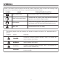
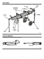
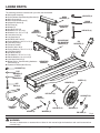
OPERATOR’S MANUAL MITER SAW UTILITY VEHICLE AC9944 Your miter saw utility vehicle has been engineered and manufactured to our high standard for dependability, ease of operation, and operator safety. When properly cared for, it will give you years of rugged, trouble-free performance. WARNING: To reduce the risk of injury, the user must read and understand the operator’s manual before using this product. Thank you for buying a RIDGID product. SAVE THIS MANUAL FOR FUTURE REFERENCE 1 TABLE OF CONTENTS Introduction ...................................................................................................................................................................... 2 Rules for Safe Operation .................................................................................................................................................. 3 Symbols ............................................................................................................................................................................ 4 Features ............................................................................................................................................................................ 5 Tools Needed .................................................................................................................................................................... 5 Loose Parts....................................................................................................................................................................... 6 Assembly .....................................................................................................................................................................7-13 Operation ...................................................................................................................................................................14-15 Maintenance ..............................................................................................................................................................16-17 Warranty ......................................................................................................................................................................... 19 Parts Ordering/Service ................................................................................................................................................... 20 INTRODUCTION This product has many features for making its use more pleasant and enjoyable. Safety, performance, and dependability have been given top priority in the design of this product making it easy to maintain and operate. 2 RULES FOR SAFE OPERATION Safe operation of this accessory requires that you read and understand this operator’s manual, the operator’s manual for the miter saw, and all labels affixed to the tool. WHEN HAULING THE WORKSTAND IN A VEHICLE, securely tie it down to prevent movement and possible damage. READ ALL INSTRUCTIONS NEVER put the workstand where operators or bystanders are forced to stand with any part of their body inline with the path of the saw blade. KNOW YOUR ACCESSORY. Read the operator’s manual carefully. Learn the product’s applications and limitations as well as the specific potential hazards related to this product. NEVER STAND ON WORKSTAND. Serious injury could occur if the stand tips or you accidentally hit the cutting tool. Do not store any items above or near the stand where anyone might climb on the stand to reach them. MAXIMUM WEIGHT OF POWER TOOL MUST NOT EXCEED 100 POUNDS. MAXIMUM WEIGHT OF SAW AND WORKPIECE MUST NOT EXCEED 200 POUNDS. ALWAYS MOUNT MITER SAW so the workpiece is positioned in-line with the roller assemblies. CHECK TO MAKE SURE WORKSTAND DOES NOT ROCK, SLIDE OR MOVE PRIOR TO USE. PUT THE WORKSTAND ON A FIRM LEVEL SURFACE where there is plenty of room to handle and properly support the workpiece. ALWAYS move mounted saw to the wheeled end of stand prior to transporting or taking down unit and ensure saw mounting brackets are securely locked. SAVE THESE INSTRUCTIONS. Refer to them frequently and use them to instruct other users. If you loan someone this product, also loan these instructions. KEEP THE WORK AREA CLEAN. Cluttered work areas and work benches invite accidents. DO NOT leave tools or pieces of wood on the saw while operating. ALWAYS WEAR SAFETY GLASSES WITH SIDE SHIELDS. Everyday eyeglasses have only impactresistant lenses; they are NOT safety glasses. DO NOT USE THIS PRODUCT WITH OTHER EQUIPMENT or for other purposes. ALWAYS DISCONNECT THE SAW FROM THE POWER SUPPLY BEFORE ASSEMBLING THIS KIT. Make sure the switch is off when reconnecting the saw to a power supply. B E F O R E M A K I N G A C U T, B E S U R E A L L ADJUSTMENTS ARE SECURE. ALWAYS GET HELP IF YOU NEED TO LIFT THE WORKSTAND. When lifting, hold the workstand close to your body. Bend your knees so you can lift with your legs, not your back. 3 SYMBOLS Some of the following symbols may be used on this product. Please study them and learn their meaning. Proper interpretation of these symbols will allow you to operate the product better and safer. SYMBOL NAME DESIGNATION/EXPLANATION Wet Conditions Alert Do not expose to rain or use in damp locations. Read The Operator’s Manual To reduce the risk of injury, user must read and understand operator’s manual before using this product. Eye Protection Always wear safety goggles or safety glasses with side shields and, as necessary, a full face shield when operating this product. Safety Alert Precautions that involve your safety. The following signal words and meanings are intended to explain the levels of risk associated with this product. SYMBOL SIGNAL MEANING DANGER: Indicates an imminently hazardous situation, which, if not avoided, will result in death or serious injury. WARNING: Indicates a potentially hazardous situation, which, if not avoided, could result in death or serious injury. CAUTION: Indicates a potentially hazardous situation, which, if not avoided, may result in minor or moderate injury. CAUTION: (Without Safety Alert Symbol) Indicates a situation that may result in property damage. 4 FEATURES WORK SUPPORT WORK STOP QUICK RELEASE SAW MOUNTING BRACKETS WORK SUPPORT BRACKET LIFT ASSIST HANDLE EXTENSION ARM LEG SUPPORT TRANSPORT HANDLE SUPPORT LEG Fig. 1 TOOLS NEEDED The following tools (not included) are needed for assembly: SCREWDRIVER ADJUSTABLE WRENCH(S) Fig. 2 5 LOOSE PARTS The following items are included with your miter saw workstand: Workstand Assembly Quick Release Saw Mounting Brackets (2) Work Supports (2) Work Support Brackets (2) Adjustment Knobs (4) End Caps (2) Wheels (2) Hex Bolts, M10 (2) WORK Washers, 24 x 13 x 2 (2) SUPPORT Washers, 20 x 10.5 x 1.5 (2) BRACKETS (2) Lock Nuts, M10 (2) Leg Supports (2) Hex Bolts, M6 x 48 (4) Spring Washers, 16 x 6.5 x 1.5 (8) Lock Nuts, M6 (4) Transport Handle Screws, M6 x 38 (3) Spring Washers, 16 x 6.5 x 1.5 (3) Lock Nuts, M6 (3) Hex Bolts, M6 (2) Flat Washers, 16 x 6.5 x 1.5 (2) Plastic Washers, 19 x 6.8 x 2 (2) Lock Nuts, M6 x 55 (2) Blister Packs - Saw Mounting Hardware WORKSTAND ASSEMBLY (Not Shown) (2) Operator’s Manual (Not Shown) LOCK NUTS (4) WORK SUPPORTS (2) SPRING WASHERS (8) ADJUSTMENT KNOBS (4) HEX BOLTS (4) QUICK RELEASE SAW MOUNTING BRACKETS (2) LEG SUPPORTS (2) LOCK NUTS (2) FLAT WASHERS (2) PLASTIC WASHERS (2) WHEELS (2) WASHERS (2) HEX BOLTS (2) HEX BOLTS (2) LOCK NUTS (2) SPRING WASHERS (3) TRANSPORT HANDLE LOCK NUTS (3) SCREWS (3) WASHERS (3) WASHERS (2) END CAPS (2) Fig. 3 WARNING: The use of attachments or accessories not listed in this manual might be hazardous and could cause serious personal injury. 6 ASSEMBLY UNPACKING RAISE LEGS This product requires assembly. LEG SET Carefully remove the product and any accessories from the box. Make sure that all items listed in the packing list are included. Inspect the product carefully to make sure no breakage or damage occurred during shipping. RELEASE LEGS Do not discard the packing material until you have carefully inspected and satisfactorily operated the product. LOCK LEGS If any parts are damaged or missing, please call 1-866-539-1710 for assistance. WARNING: If any parts are damaged or missing do not operate this product until the parts are replaced. Failure to heed this warning could result in serious personal injury. LOCK KNOB Fig. 4 WHEEL RELEASE LEVER ROTATE LIFT ASSIST HANDLE WARNING: Do not attempt to modify this product or create accessories not recommended for use with this product. Any such alteration or modification is misuse and could result in a hazardous condition leading to possible serious personal injury. CABLE TIE RAISE WHEEL LEGS AND LOCK INTO POSITION 3 4 1 WARNING: Do not connect to power supply until assembly is complete. Failure to comply could result in accidental starting and possible serious personal injury. 2 HOLD WHEEL LEG SET FIRMLY P R E PA R I N G T H E W O R K S TA N D F O R ASSEMBLY SPRING LOADED WHEEL LEG SET See Figures 4 - 5. With workstand out of box and packaging removed, place unit upside down on ground. Fig. 5 Pull lock knob on leg set and raise legs until locked into open position. Pull up on lock mechanism release lever and carefully raise wheel legs. Rotate lift assist handle to operational position. Continue to raise wheel leg set until locked into position. While holding spring loaded wheel leg set firmly, cut cable tie. CAUTION: Wheel legs are spring loaded. Hold wheel legs to prevent from snapping up when releasing lock mechanism release lever. Failure to do so may result in possible injury. 7 ASSEMBLY SECURING THE LIFT ASSIST HANDLE See Figures 5 - 6. Insert hex bolt into hole on each side of handle but do not insert through stand table. WASHER LOCK NUT Insert plastic washer between handle and stand table onto the bolt. Push bolt through the hole in the stand table. HEX BOLT Place a washer and lock nut over each bolt and secure. Do not overtighten. ATTACHING THE LEG SUPPORTS PLASTIC WASHER See Figure 7. Insert leg support into wheel leg set with foot peddle side facing down toward lift assist handle. Align the two holes in the leg support with the holes in the assembly. Place a spring washer over the hex bolt and insert up through each leg hole. Place a spring washer and lock nut over end of each bolt and secure. LIFT ASSIST HANDLE Fig. 6 HEX BOLT Repeat on other side. WHEEL LEG SET LEG SUPPORT LOCK NUT SPRING WASHER SPRING WASHER HEX BOLT Fig. 7 8 ASSEMBLY ATTACHING THE TRANSPORT HANDLE See Figure 8. Align transport handle ends with holes in stand table end caps and insert. TRANSPORT HANDLE Place a spring washer over the screw and insert screw through each hole of the handle and leg support bracket. Place a washer and lock nut over the end of each screw and secure. ATTACHING THE WHEELS See Figure 9. Insert bolt through wheel leg set. Place washer and then wheel over bolt. Place washer and lock nut over end of bolt and secure. SCREW Do not overtighten. END CAP Place end cap over lock nut. LOCK NUT SPRING WASHER Repeat on other side. WASHER Fig. 8 WHEEL WASHER After wheels are installed and all previous assembly procedures have been followed, workstand may be turned over to rest on its legs. WASHER NOTE: The workstand is heavy. Get help when needed. INSTALLING THE WORK SUPPORTS HEX BOLT LOCK NUT See Figure 10. The work supports support the workpiece during cutting operations. To install the work supports: LEG ASSEMBLY Loosen lock lever and slide extension arm out for accessibility. Position work support bracket so that the work support shaft is positioned in the center of the stand table. Fig. 9 Align large square hole in work support bracket with end of extension arm and slide bracket over rail. Insert the work support in shaft of bracket. Insert adjustment knob through knob hole in shaft of bracket and tighten to secure into position. WORK SUPPORT Insert adjustment knob through knob hole on top of bracket and tighten to secure into position. Repeat on the other side. ADJUSTMENT KNOB SHAFT Ensure workstand is stable and can be opened and locked. WORK SUPPORT EXTENSION BRACKET ARM LOCK LEVER TIGHTEN 9 LOOSEN Fig. 10 ASSEMBLY WARNING: HEX NUT The saw mounting brackets are designed to fit snugly over the table edges with locking levers in the open position. With the locking levers in the lowered (locked) position, you should not be able to slide the saw mounting bracket assembly along the table edges or remove the bracket assembly from the table edges. If the saw mounting brackets will not fit over the edges, or if the brackets can be removed from the edges when the levers are locked, remove bracket assembly immediately and adjust bracket adjustment screw. See the Maintenance section of this manual. Failure to heed this warning may result in serious personal injury. LOCK WASHER FLAT WASHER 10 30 35 40 45 25 15 20 SAW ARM AT TA C H I N G S AW T O T H E M O U N T I N G BRACKETS STABLE SUPPORT CARRIAGE BOLT See Figures 11 - 12. Always position the saw to achieve maximum balance and stability. All four corners of the saw must be bolted to the mounting brackets before use. Make sure bolts do not extend above the table of the miter saw. SLIDING ADJUSTMENT PLATE CARRIAGE BOLT LOADING SLOTS SAW MOUNTING BRACKET Fig. 11 NOTE: Four additional 1-1/2 in. bolts have been provided for use when securing a sliding miter saw to the mounting brackets. NOTE: Ensure that mounting brackets can be clamped securely onto stand before mounting saw. If locking lever on saw mounting bracket cannot easily be pushed down into the closed position, the adjustment screw is too tight. Do not force locking lever into the closed position. Loosen the adjustment screw. Refer to the Maintenance section later in this manual for mounting bracket adjustment. HEX NUT LOCK WASHER FLAT WASHER 10 If the saw has mounting holes that line up with the slots in the saw mounting brackets: 45 40 35 30 25 20 15 Disconnect the saw from power supply and lock the saw arm in the down position. Place a 2 x 4 or similar type of stable support underneath the saw to raise the saw and allow access to the saw’s mounting feet. HEX BOLT Feed a carriage bolt up through each side of the bracket and adjustment plate. SAW MOUNTING BRACKET Align bolts in the two sliding adjustment plates on the saw mounting bracket with the saw mounting holes. CARRIAGE BOLT Place the saw mounting bracket underneath the raised side of the saw, and insert bolts through mounting holes in saw. Fig. 12 Disconnect the saw from power supply and lock saw arm in the down position. Loosely secure in place using a flat washer, lock washer, and hex nut. Mount the saw to a mounting surface at least 1/2 in. thick using 5/16 hex head bolts, washers, and nuts (not included). Repeat procedure to attach second bracket to saw. After making sure both brackets are parallel to each other, lightly tighten all four nuts to hold in position. If the saw has holes that do not line up with the sliding adjustment plates in the saw mounting brackets: MOUNTING SURFACE Drill holes in the mounting surface to match the sliding adjustment plates in the saw mounting brackets. Proceed with installation as previously described. 10 ASSEMBLY M O U N T I N G T H E M I T E R S AW T O T H E WORKSTAND NOTE: Continue to hold the saw and bracket assembly with one hand until both levers are securely locked. Check position and adjust, if necessary, to make sure the weight of the saw is evenly balanced over the edges. See Figures 13 - 14. Use the handles located at the rear of the saw mounting brackets to aid in installing or removing saw and bracket assembly. Ensure the saw is fully seated and locked in position, then securely tighten the four nuts holding the saw to the saw mounting brackets. L � ift the saw and bracket assembly, allowing the assembly to tilt slightly toward your body. WARNING: While still tilted toward you, hook the front clamp of the saw and bracket assembly onto the front edge of the table. The saw mounting brackets are designed to fit snugly over the table edges with locking levers in the open position. With the locking levers in the lowered (locked) position, you should not be able to slide the saw mounting bracket assembly along the table edges or remove the bracket assembly from the table edges. If the saw mounting brackets will not fit over the edges, or if the brackets can be removed from the edges when the levers are locked, remove bracket assembly immediately and adjust bracket adjustment screw. See the Maintenance section of this manual. Failure to heed this warning may result in serious personal injury. WARNING: To avoid serious personal injury, make sure the curved front edge of the mounting brackets are securely seated over the front edge of table before seating the other end of the brackets. Failure to do so could cause you to lose control of the saw and bracket assembly, which could cause serious personal injury. Lower the saw and bracket assembly to allow the rear clamp of the bracket to seat fully over the rear table edge. Lock the brackets in position by lowering the locking levers. 10 45 40 35 30 45 40 35 30 25 20 15 HANDLES LOCKING LEVER PUSH DOWN AND BACK TO LOCK Fig. 13 11 ASSEMBLY LOCKING LEVER RELEASE BUTTON �To remove saw from workstand: Push locking lever release buttons and raise the locking levers to unlock the saw mounting brackets assembly. PUSH IN AND LIFT TO UNLOCK � Grasp the handles on either side of the assembly and lift away from the rear edge of the table to disengage. �With the assembly tilted slightly toward you, lift the front part of the assembly to disengage from the front edge of the table. LIFT TO RELEASE LEVER CAUTION: LOCKING LEVER Do not mount miter saw to workstand before ensuring workstand can be opened and locked securely. Failure to do so may result in possible injury and damage to the tool. OPENING THE WORKSTAND See Figures 15 - 16. SETUP: NOTE: If saw is mounted, ensure that saw is in folding transportation position. See figure 17. 10 45 40 35 30 15 20 25 From the upright position, pull the lock knob and lift legs up until the spring pin locks into place. WARNING: Fig. 14 To reduce the risk of injury, make sure leg set is secured in the notch by the lock knob. Failure to latch may cause workstand to fall in use. SETUP INSTA LLATION INSTA LE FOLD DOWN PLI VERS DOBLEZ LE BAS ABAJO Slowly lower workstand until the legs rest on the ground. Stand at wheel end of workstand and grasp the lift assist handle. Push down on lock mechanism release lever and lift workstand into raised position. ENS URE ASSU TOO REZ-V L IS OUS QUE AT L’OUT “WH DE QUE IL SE EEL LA HERRA TROU END VE MIENT À LA ” OF A ESTÉ MÊME STA EN EL EXTR EXTRE ND ÉMITÉ MO BEF DEL DU ORE BANCO SUPP ORT CORRE FOL QUE SPOND DIN LES G/ IENTE ROUE TRA A LAS S AVAN NSP RUEDA T DE S ANTES ORT PLIER ING DE /TRAN DESPL SPOR EGAR/ TER TRANS ASEGÚ RESE AV ER TIS SE ME NT AD Mit PORTA R er VE RT EN CIA NOTE: The workstand is heavy. Get help when needed. WARNING: To avoid serious personal injury when lifting, bend your knees so you can lift with your legs, not your back. LOCK MECHANISM RELEASE LEVER CAUTION: Do not lift by any part of the miter saw that is attached to the workstand. Failure to heed this warning may result in possible injury and damage the tool. Step on leg support while lifting table up by lift assist handle. The wheels should move further under workstand until unit is locked into place. Ensure workstand is locked into position before use. 12 Fig. 15 ASSEMBLY CLOSING AND MOVING THE WORKSTAND SETUP See Figures 15 - 17. NOTE: The workstand is heavy. Get help when needed. INSTALLATION INSTALE FOLD DOWN PLI VERS LE BAS DOBLEZ ABAJO If a miter saw is assembled on the stand, make sure to place the blade 90° to the table (if applicable), miter the blade to the right as far as it will go, place the blade in the “locked down” position, and lock all knobs and levers. NOTE: If a sliding compound miter saw is mounted on the stand, it may be necessary to slide the power head/blade assembly forward and lock in place when going through doorways or other narrow openings. Remove any workpieces, clamps, or other accessories from saw. FOLD DOWN: Move miter saw to wheel end of workstand and secure per the instructions in this manual. See figure 17. Make sure extension arms and support legs are retracted into position behind transport handle and lift assist handle. While securely gripping lift assist handle, push down lock mechanism release lever to release wheel leg set. Slowly push stand down to the ground in one controlled movement. CAUTION: Leg supports will move toward you when stand is being lowered. Be aware of their position to avoid possible injury. SECURELY GRIP AND HOLD ASSIST HANDLE FIRMLY WHEN SETTING UP OR FOLDING DOWN STAND SERREZ BIEN ET TENEZ FERMEMENT LA POIGNÉE AUXILIAIRE QUAND VOUS OUVREZ OU PLIEZ LE SUPPORT SUJETE Y SOSTENGA EL MANGO DE APOYO FIRMEMENTE Y EN FORMA SEGURA AL DESPLEGAR O PLEGAR EL BANCO Fig. 16 Use transport handles to lift stand into upright position. Make sure the stand will remain upright on its own. CAUTION: If the stand will not remain upright, store in the horizontal position. Pull the lock knob and push leg set in under workstand until they lock into place. AVERTISSEMENT The workstand can be moved by pulling or pushing. To keep the stand from tipping over, pulling the stand is the preferred method when moving over a door threshold, crack, or up stairs. ADVERTENCIA ENSURE TOOL IS AT “WHEEL END” OF STAND BEFORE FOLDING/ TRANSPORTING ASSUREZ-VOUS QUE L’OUTIL SE TROUVE À LA MÊME EXTRÉMITÉ DU SUPPORT QUE LES ROUES AVANT DE PLIER/TRANSPORTER ASEGÚRESE DE QUE LA HERRAMIENTA ESTÉ EN EL EXTREMO DEL BANCO CORRESPONDIENTE A LAS RUEDAS ANTES DE DESPLEGAR/TRANSPORTAR Fig. 17 13 OPERATION WARNING: Do not allow familiarity with products to make you careless. Remember that a careless fraction of a second is sufficient to inflict severe injury. EXTENSION ARM WARNING: Always wear safety goggles or safety glasses with side shields when operating products. Failure to do so could result in objects being thrown into your eyes resulting in possible serious injury. ADJUST IN - OUT 10 45 40 35 30 25 20 EXTENSION ARM LOCKING LEVER 15 WARNING: TIGHTEN LOOSEN Do not use any attachments or accessories not recommended by the manufacturer of this tool. The use of attachments or accessories not recommended can result in serious personal injury. LATCH ON UNDERSIDE PULL LEG EXTENSION OUTWARD APPLICATIONS You may use this product for the purpose listed below: Fig. 18 HINGE POINT RELEASE BUTTON To provide a stable, secure work surface for a miter saw USING THE EXTENSION ARMS AND SUPPORT LEGS See Figures 18 - 19. Use the extension arms when working with larger workpieces. Both extension arms may be adjusted to provide maximum workpiece support. PULL LEG DOWN EXTENSION ARM To extend the extension arms: Loosen the extension arm locking lever. Extend the extension arm to the desired position. Tighten the extension arm locking lever. To extend the support legs: SUPPORT LEG Press latch at end of extension arm and pull leg outward from arm until hinge is fully exposed. The leg will bend at hinge and face in a downward position. Press and hold latch in middle of support leg. Extend adjustment leg completely to the ground. ADJUSTMENT LEG EXTENSION ARM LOCKING LEVER To retract extension arms and support legs: Press and hold latch in middle of support leg to release adjustment leg. Push adjustment leg into support leg until it locks into place. Push release button on hinge and rotate support leg into horizontal position. Push support leg into extension arm until locked into position. LATCH Unlock the extension arm locking lever. ADJUST LEG EXTENSION UNTIL STABLE Push extension arm fully into stand for storage. Lock the extension arm locking lever. 14 Fig. 19 OPERATION USING THE WORK SUPPORT To adjust the work support: See Figure 20. Rest the workpiece on top of the work support to support the workpiece during cutting operations. Loosen the work support height adjustment knob. NOTE: More than one work support can be used on an extension arm at a time when extra support is necessary. Always lower extension arm support legs when using work supports. Lower extension arm support leg. Adjust the work support to the desired position. Tighten the work support height adjustment knob. To adjust work support distance: Loosen the work support distance adjustment knob. Rest the workpiece on the work support work stop whenever you need to make repetitive cuts of the same size. Slide the work support to the desired position along the extension arm. NOTE: To avoid a greater risk of binding or pinching, do not use both work support at the same time when using the work stop feature. Tighten the work support distance adjustment knob. Lower extension arm support leg. WORK SUPPORT ADJUST WORK SUPPORT UP AND DOWN DISTANCE ADJUSTMENT KNOB ADJUST WORK SUPPORT IN AND OUT WORK STOP 10 45 40 35 30 25 20 15 HEIGHT ADJUSTMENT KNOB SUPPORT LEG EXTENSION ARM Fig. 20 15 MAINTENANCE LOCK MECHANISM HINGE WARNING: When servicing use only identical RIDGID replacement parts. Use of any other parts may create a hazard or cause product damage. WARNING: Always wear safety goggles or safety glasses with side shields during power tool operation or when blowing dust. If operation is dusty, also wear a dust mask. GENERAL MAINTENANCE Avoid using solvents when cleaning plastic parts. Most plastics are susceptible to damage from various types of commercial solvents and may be damaged by their use. Use clean cloths to remove dirt, dust, oil, grease, etc. WARNING: Do not at any time let brake fluids, gasoline, petroleum-based products, penetrating oils, etc., come in contact with plastic parts. Chemicals can damage, weaken or destroy plastic which may result in serious personal injury. Periodically check all fasteners for tightness. Retighten as necessary. CLEANING AND LUBRICATING Fig. 21 See Figures 21 - 22. Clean and lubricate the lock mechanism hinge. SPRING CYLINDER SHAFT Lubricate the spring cylinder shaft. Fig. 22 16 MAINTENANCE SAW MOUNTING BRACKET WARNING: The saw mounting brackets are designed to fit snugly over the table edges with locking levers in the open position. With the locking levers in the lowered (locked) position, you should not be able to slide the saw mounting bracket assembly along the table edges or remove the bracket assembly from the table edges. If the saw mounting brackets will not fit over the edges, or if the brackets can be removed from the edges when the levers are locked, remove bracket assembly immediately and adjust bracket adjustment screw. Failure to heed this warning may result in serious personal injury. WRENCH SAW MOUNTING BRACKET ADJUSTMENT See Figure 23. If the saw and bracket assembly can slide over the table edges or be removed from the table edges when the levers are locked, the bracket adjustment screws need to be tightened. If the saw and bracket assembly will not fit over both table edges, the bracket adjustment screw needs to be loosened. SCREWDRIVER NUT BRACKET ADJUSTMENT SCREW NOTE: The saw should be removed from the mounting brackets before attempting to tighten or loosen the bracket adjustment screws. To adjust: Use a wrench to slightly loosen the nut. Turn the screw with a phillips screwdriver. Rotate clockwise if the bracket assembly needs to be tightened or counterclockwise if the assembly needs to be loosened. NOTE: If locking lever on saw mounting bracket cannot easily be pushed down into the closed position, the adjustment screw is too tight. Do not force locking lever into the closed position. Loosen the adjustment screw. Install the bracket on the front table edge then lower bracket to allow the rear clamp of the bracket to seat fully over the rear table edge. NOTE: The mounting bracket should fit snugly over the table edges when in the open position. When the correct position is achieved, wrench-tighten the nut to secure. Repeat with the second mounting bracket. To purchase additional saw mounting bracket assemblies (part no. 900510802), call RIDGID customer service at 1-866-539-1710. 17 SCREWDRIVER ACCESS HOLE Fig. 23 NOTES 18 WARRANTY RIDGID® HAND HELD AND STATIONARY POWER TOOL 3 YEAR LIMITED SERVICE WARRANTY WHAT IS NOT COVERED Proof of purchase must be presented when requesting warranty service. This warranty applies only to the original purchaser at retail and may not be transferred. This warranty only covers defects arising under normal usage and does not cover any malfunction, failure or defect resulting from misuse, abuse, neglect, alteration, modification or repair by other than an authorized service center for RIDGID® branded hand held and stationary power tools. Consumable accessories provided with the tool such as, but not limited to, blades, bits and sand paper are not covered. Limited to RIDGID® hand held and stationary power tools purchased 2/1/04 and after. This product is manufactured by One World Technologies, Inc. The trademark is licensed from RIDGID, Inc. All warranty communications should be directed to One World Technologies, Inc., attn: RIDGID Hand Held and Stationary Power Tool Technical Service at (toll free) 1-866-539-1710. 90-DAY SATISFACTION GUARANTEE POLICY RIDGID, INC. AND ONE WORLD TECHNOLOGIES, INC. MAKE NO WARRANTIES, REPRESENTATIONS OR PROMISES AS TO THE QUALITY OR PERFORMANCE OF ITS POWER TOOLS OTHER THAN THOSE SPECIFICALLY STATED IN THIS WARRANTY. During the first 90 days after the date of purchase, if you are dissatisfied with the performance of this RIDGID® Hand Held and Stationary Power Tool for any reason you may return the tool to the dealer from which it was purchased for a full refund or exchange. To receive a replacement tool you must present proof of purchase and return all original equipment packaged with the original product. The replacement tool will be covered by the limited warranty for the balance of the 3 YEAR service warranty period. ADDITIONAL LIMITATIONS To the extent permitted by applicable law, all implied warranties, including warranties of MERCHANTABILITY or FITNESS FOR A PARTICULAR PURPOSE, are disclaimed. Any implied warranties, including warranties of merchantability or fitness for a particular purpose, that cannot be disclaimed under state law are limited to three years from the date of purchase. One World Technologies, Inc. and RIDGID, Inc. are not responsible for direct, indirect, incidental or consequential damages. Some states do not allow limitations on how long an implied warranty lasts and/or do not allow the exclusion or limitation of incidental or consequential damages, so the above limitations may not apply to you. This warranty gives you specific legal rights, and you may also have other rights which vary from state to state. WHAT IS COVERED UNDER THE 3 YEAR LIMITED SERVICE WARRANTY This warranty on RIDGID® Hand Held and Stationary Power Tools covers all defects in workmanship or materials and normal wear items such as brushes, chucks, motors, switches, cords, gears and even cordless batteries in this RIDGID® tool for three years following the purchase date of the tool. Warranties for other RIDGID® products may vary. HOW TO OBTAIN SERVICE To obtain service for this RIDGID® tool you must return it; freight prepaid, or take it in to an authorized service center for RIDGID® branded hand held and stationary power tools. You may obtain the location of the authorized service center nearest you by calling (toll free) 1-866-539-1710 or by logging on to the RIDGID® website at www.ridgid.com. When requesting warranty service, you must present the original dated sales receipt. The authorized service center will repair any faulty workmanship, and either repair or replace any part covered under the warranty, at our option, at no charge to you. One World Technologies, Inc. P.O. Box 35, Hwy. 8 Pickens, SC 29671 19 OPERATOR’S MANUAL MITER SAW UTILITY VEHICLE AC9944 Customer Service Information: For parts or service, contact your nearest RIDGID authorized service center. Be sure to provide all relevant information when you call or visit. For the location of the authorized service center nearest you, please call 1-866-539-1710 or visit us online at www.ridgid.com. The model number of this product is found on a plate attached to the bottom of the table. Please record the serial number in the space provided below. When ordering repair parts, always give the following information: AC9944 Model No. Serial No. 987000-043 1-11-07 (REV:01) 20