1
SPLIT-TYPE, HEAT PUMP AIR CONDITIONERS
December 2012
TECHNICAL & SERVICE MANUAL
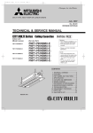
Series PMFY Ceiling Cassettes R410A
Indoor unit
[Model names] [Service Ref.]
PMFY-P20VBM-E
PMFY-P25VBM-E
PMFY-P32VBM-E
PMFY-P40VBM-E
PMFY-P20VBM-E
PMFY-P20VBM-E#2
PMFY-P20VBM-ER4
PMFY-P25VBM-E
PMFY-P25VBM-E#2
PMFY-P25VBM-ER4
PMFY-P32VBM-E
PMFY-P32VBM-E#2
PMFY-P32VBM-ER4
PMFY-P40VBM-E
PMFY-P40VBM-E#2
PMFY-P40VBM-ER4
PMFY-P20VBM-E1
PMFY-P20VBM-ER3
PMFY-P25VBM-E1
PMFY-P25VBM-ER3
PMFY-P32VBM-E1
PMFY-P32VBM-ER3
PMFY-P40VBM-E1
PMFY-P40VBM-ER3
No. OC307
REVISED EDITION-E
Revision:
• PMFY-P20/25/32/40VBM-ER4
have been added in
REVISED EDITION-E.
• Some descriptions have
been modified.
• Please void OC307
REVISED EDITION-D.
Note:
• This manual describes
only service data of the
indoor units.
• RoHS compliant products
have <G> mark on the
spec name plate.
• For servicing RoHS compliant products, refer to
the RoHS Parts List.
CONTENTS
1.
2.
3.
4.
5.
6.
7.
8.
9.
10.
INDOOR UNIT
TECHNICAL CHANGES..................... 2
SAFETY PRECAUTION ..................... 3
PART NAMES AND FUNCTIONS ...... 5
SPECIFICATIONS ............................ 12
OUTLINES AND DIMENSIONS ....... 16
WIRING DIAGRAM........................... 17
REFRIGERANT SYSTEM DIAGRAM .... 21
TROUBLE SHOOTING..................... 22
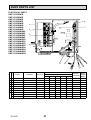
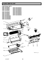
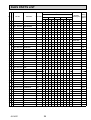
DISASSEMBLY PROCEDURE......... 32
RoHS PARTS LIST........................... 36
1
TECHNICAL CHANGES
PMFY-P20VBM-ER3
PMFY-P25VBM-ER3
PMFY-P32VBM-ER3
PMFY-P40VBM-ER3
PMFY-P20VBM-ER4
PMFY-P25VBM-ER4
PMFY-P32VBM-ER4
PMFY-P40VBM-ER4
1. INDOOR CONTROLLER BOARD has been changed. (S/W version up)
PMFY-P20VBM-E#2
PMFY-P25VBM-E#2
PMFY-P32VBM-E#2
PMFY-P40VBM-E#2
PMFY-P20VBM-ER3
PMFY-P25VBM-ER3
PMFY-P32VBM-ER3
PMFY-P40VBM-ER3
1. DRAIN PIPE has been changed.
2. JOINT SOCKET (FOR DRAIN PIPE) has been added.
PMFY-P20VBM-E1
PMFY-P25VBM-E1
PMFY-P32VBM-E1
PMFY-P40VBM-E1
PMFY-P20VBM-E#2
PMFY-P25VBM-E#2
PMFY-P32VBM-E#2
PMFY-P40VBM-E#2
1. CONTROLLER BOARD (I.B) has been changed.
2. PANEL has been changed.
PMP-40BM
→
PMP-40BMW
(White : 0.98Y 8.99/0.63)
(Pure white : 6.4Y 8.9/0.4)
3. FAN MOTOR (MF) has been changed.
4. THERMISTOR (TH22, TH23) have been changed.
PMFY-P20VBM-E
PMFY-P25VBM-E
PMFY-P32VBM-E
PMFY-P40VBM-E
PMFY-P20VBM-E1
PMFY-P25VBM-E1
PMFY-P32VBM-E1
PMFY-P40VBM-E1
1. FAN MOTOR (MF) has been changed.
2. CONTROLLER BOARD (I.B) has been changed.
OC307E
2
2
SAFETY PRECAUTION
Cautions for units utilizing refrigerant R410A
Use new refrigerant pipes.
In case of using the existing pipes for R22, be careful with
the followings.
· Change flare nut to the one provided with this product.
Use a newly flared pipe.
· Avoid using thin pipes.
Make sure that the inside and outside of refrigerant piping is clean and it has no contaminants
such as sulfur, oxides, dirt, shaving particles, etc,
which are hazard to refrigerant cycle.
In addition, use pipes with specified thickness.
Contamination inside refrigerant piping can cause deterioration of refrigerant oil etc.
Vacuum pump oil may flow back into refrigerant cycle and
that can cause deterioration of refrigerant oil etc.
Use the following tools specifically designed for
use with R410A refrigerant.
The following tools are necessary to use R410A refrigerant.
Gauge manifold
Charge hose
Gas leak detector
Torque wrench
Tools for R410A
Flare tool
Size adjustment gauge
Vacuum pump adaptor
Electronic refrigerant
charging scale
Handle tools with care.
Store the piping indoors, and both ends of the
piping sealed until just before brazing.
(Leave elbow joints, etc. in their packaging.)
If dirt, dust or moisture enters into refrigerant cycle, that can
cause deterioration of refrigerant oil or malfunction of compressor.
If dirt, dust or moisture enters into refrigerant cycle, that can
cause deterioration of refrigerant oil or malfunction of compressor.
Do not use a charging cylinder.
If a charging cylinder is used, the composition of refrigerant will change and the efficiency will be lowered.
The refrigerant oil applied to flare and flange
connections must be ester oil, ether oil or
alkylbenzene oil in a small amount.
If large amount of mineral oil enters, that can cause deterioration of refrigerant oil etc.
Charge refrigerant from liquid phase of gas
cylinder.
If the refrigerant is charged from gas phase, composition
change may occur in refrigerant and the efficiency will be
lowered.
Use the specified refrigerant only.
Never use any refrigerant other than that specified.
Doing so may cause a burst, an explosion, or fire when the
unit is being used, serviced, or disposed of.
Correct refrigerant is specified in the manuals and on the
spec labels provided with our products.
We will not be held responsible for mechanical failure,
system malfunction, unit breakdown or accidents caused
by failure to follow the instructions.
Ventilate the room if refrigerant leaks during
operation. If refrigerant comes into contact with
a flame, poisonous gases will be released.
Do not use refrigerant other than R410A.
If other refrigerant (R22 etc.) is used, chlorine in refrigerant can cause deterioration of refrigerant oil etc.
OC307E
Use a vacuum pump with a reverse flow check
valve.
3
[1] Cautions for service
(1) Perform service after recovering the refrigerant left in unit completely.
(2) Do not release refrigerant in the air.
(3) After completing service, charge the cycle with specified amount of refrigerant.
(4) When performing service, install a filter drier simultaneously.
Be sure to use a filter drier for new refrigerant.
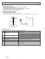
[2] Additional refrigerant charge
When charging directly from cylinder
· Check that cylinder for R410A on the market is syphon type.
· Charging should be performed with the cylinder of syphon stood vertically. (Refrigerant is charged from liquid phase.)
Unit
Gravimeter
[3] Service tools
Use the below service tools as exclusive tools for R410A refrigerant.
No.
1
Tool name
Specifications
Gauge manifold
· Only for R410A
· Use the existing fitting specifications. (UNF1/2)
· Use high-tension side pressure of 5.3MPa·G or over.
2
Charge hose
· Only for R410A
3
Electronic scale
4
Gas leak detector
· Use the detector for R134a, R407C or R410A.
5
Adapter for reverse flow check
· Attach on vacuum pump.
6
Refrigerant charge base
7
Refrigerant cylinder
· Use pressure performance of 5.09MPa·G or over.
—
—
· Only for R410A
· Top of cylinder (Pink)
· Cylinder with syphon
8
—
Refrigerant recovery equipment
OC307E
4
3
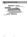
PART NAMES AND FUNCTIONS
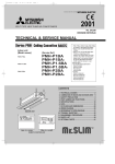
3-1. Indoor Unit
Auto Air Swing Vane
Disperses airflow up and
down and adjusts the angle
of airflow direction.
Guide vane
Air flow can be changed to horizontal
by moving the Guide vane to the left or right.
Horizontal Air Outlet
Filters
Remove dust and pollutants
from return air.
OC307E
Air intake
Returns air from room.
5
3-2. WIRED REMOTE CONTROLLER <PAR-30MAA/PAR-31MAA>
Wired remote controller function
* The functions which can be used are restricted according to the model.
Function
Body
: Supported
PAR-30MAA/PAR-31MAA
Slim
Product size H × W × D (mm)
LCD
: Unsupported
PAR-21MAA
City multi
120 × 120 × 19
120 × 130 × 19
Full Dot LCD
Partial Dot LCD
Backlight
Energy-saving
Energy-saving operation schedule
Automatic return to the preset temperature
Restriction
Setting the temperature range restriction
Function
Operation lock function
Weekly timer
On / Off timer
High Power
Manual vane angle
The functions of the function buttons change depending on
the screen. Refer to the button function guide that appears
at the bottom of the LCD for the functions they serve on a
given screen.
When the system is centrally controlled, the button function
guide that corresponds to the locked button will not appear.
<Main display>
<Main menu>
Fri
Room
Cool
Set temp.
Auto
Mode
Temp.
Fan
Function buttons
F1
F2
F3
Main menu
Vane·Louver·Vent. (Lossnay)
High power
Timer
Weekly timer
OU silent mode
Main display:
Cursor
Page
Function guide
F4
ON / OFF lamp
ON / OFF button
This lamp lights up in green while the unit is in operation.
It blinks while the remote controller is starting up or when
there is an error.
Press to turn ON/OFF the indoor unit.
SELECT button
Press to save the setting.
Function button F1
RETURN button
Main display : Press to change the operation mode.
Main menu : Press to move the cursor down.
Press to return to the previous screen.
Function button F2
MENU button
Main display : Press to decrease temperature.
Main menu : Press to move the cursor up.
Press to bring up the Main menu.
Backlit LCD
Function button F3
Operation settings will appear.
When the backlight is off, pressing any button turns the
backlight on and it will stay lit for a certain period of time
depending on the screen.
Main display : Press to increase temperature.
Main menu : Press to go to the previous page.
Function button F4
Main display : Press to change the fan speed.
Main menu : Press to go to the next page.
When the backlight is off, pressing any button turns
the backlight on and does not perform its function.
(except for the
(ON / OFF) button)
OC307E
Main
6
The main display can be displayed in two different modes: "Full" and "Basic".
The factory setting is "Full". To switch to the "Basic" mode, change the setting on the Main display setting.
<Full mode>
<Basic mode>
* All icons are displayed for explanation.
Fri
Fri
Cool
Room
Cool
Set temp.
Mode
Temp.
Set temp.
Auto
Auto
Mode
Fan
Temp.
Fan
Operation mode
Indoor unit operation mode appears here.
Appears when the buttons are locked.
Preset temperature
Preset temperature appears here.
Appears when the On/Off timer or Night setback function is
enabled.
Clock (See the Installation Manual.)
Current time appears here.
Fan speed
Appears when the Weekly timer is enabled.
Fan speed setting appears here.
Button function guide
Appears while the units are operated in the energy-save
mode.
Functions of the corresponding buttons appear here.
Appears when the ON/OFF operation is centrally controlled.
Appears when the operation mode is centrally controlled.
Appears when the built-in thermistor on the remote controller is activated to monitor the room temperature.
appears when the thermistor on the indoor unit is activated to monitor the room temperature.
Appears when the preset temperature is centrally controlled.
Indicates the vane setting.
Appears when the f lter reset function is centrally controlled.
Indicates the louver setting.
Indicates when f lter needs maintenance.
Room temperature
(See the Installation Manual.)
Indicates the ventilation setting.
Current room temperature appears here.
Appears when the preset temperature range is restricted.
Most settings (except ON / OFF, mode, fan speed, temperature) can be made from the Menu screen.
OC307E
7
Menu structure
Main menu
Press the MENU button.
Move the cursor to the desired item with the
F1
and
F2
buttons, and press the SELECT button.
Vane · Louver · Vent. (Lossnay)
High power
Timer
On / Off timer
Auto-Off timer
Filter information
Error information
Weekly timer
Energy saving
Auto return
Schedule
Night setback
Restriction
Temp. range
Operation lock
Maintenance
Auto descending panel
Manual vane angle
Initial setting
Main / Sub
Clock
Main display
Contrast
Display details
Auto mode
Administrator password
Language selection
Service
Service menu
Test run
Drain pump test run
Input maintenance info.
Function setting
Lossnay (City Multi only)
Check
Self check
Maintenance password
Remote controller check
Not all functions are available on all models of indoor units.
OC307E
8
Main menu list
Setting and display items
Setting details
Vane · Louver · Vent.
(Lossnay)
Use to set the vane angle.
• Select a desired vane setting from f ve different settings.
Use to turn ON / OFF the louver.
• Select a desired setting from "ON" and "OFF."
Use to set the amount of ventilation.
• Select a desired setting from "Off," "Low," and "High."
High power
Use to reach the comfortable room temperature quickly.
• Units can be operated in the High-power mode for up to 30 minutes.
Timer
On/Off timer
Use to set the operation On/Off times.
• Time can be set in 5-minute increments.
* Clock setting is required.
Auto-Off
timer
Use to set the Auto-Off time.
• Time can be set to a value from 30 to 240 in 10-minute increments.
Filter information
Use to check the f lter status.
• The f lter sign can be reset.
Error information
Use to check error information when an error occurs.
• Error code, error source, refrigerant address, unit model, manufacturing number, contact
information (dealer's phone number) can be displayed.
* The unit model, manufacturing number, and contact information need to be registered in
advance to be displayed.
Weekly timer
Use to set the weekly operation On / Off times.
• Up to eight operation patterns can be set for each day.
* Clock setting is required.
* Not valid when the On/Off timer is enabled.
Energy
saving
Auto return
Use to get the units to operate at the preset temperature after performing energy-save
operation for a specif ed time period.
• Time can be set to a value from 30 and 120 in 10-minute increments.
* This function will not be valid when the preset temperature ranges are restricted.
Schedule
Set the start/stop times to operate the units in the energy-save mode for each day of the
week, and set the energy-saving rate.
• Up to four energy-save operation patterns can be set for each day.
• Time can be set in 5-minute increments.
• Energy-saving rate can be set to a value from 0% or 50 to 90% in 10% increments.
* Clock setting is required.
Night setback
Restriction
Use to make Night setback settings.
• Select "Yes" to enable the setting, and "No" to disable the setting. The temperature range and
the start/stop times can be set.
* Clock setting is required.
Temp. range
Use to restrict the preset temperature range.
• Different temperature ranges can be set for different operation modes.
Operation
lock
Use to lock selected functions.
• The locked functions cannot be operated.
Maintenance Auto
descending
panel
Manual
vane angle
Initial setting Main/Sub
Clock
Auto descending panel (Optional parts) Up / Down you can do.
Use to set the vane angle for each vane to a f xed position.
When connecting two remote controllers, one of them needs to be designated as a sub
controller.
Use to set the current time.
Main display Use to switch between "Full" and "Basic" modes for the Main display.
• The default setting is "Full."
Contrast
OC307E
Use to adjust screen contrast.
9
Setting and display items
Initial setting Display
details
Auto mode
Setting details
Make the settings for the remote controller related items as necessary.
Clock: The factory settings are "Yes" and "24h" format.
Temperature: Set either Celsius (°C) or Fahrenheit (°F).
Room temp. : Set Show or Hide.
Auto mode: Set the Auto mode display or Only Auto display.
Whether or not to use the AUTO mode can be selected by using the button.
This setting is valid only when indoor units with the AUTO mode function are connected.
Administrator The administrator password is required to make the settings for the following items.
password
• Timer setting • Energy-save setting • Weekly timer setting
• Restriction setting • Outdoor unit silent mode setting • Night set back
Service
Language
selection
Test run
Use to select the desired language.
Select "Test run" from the Service menu to bring up the Test run menu.
• Test run • Drain pump test run
Input
Select "Input maintenance Info." from the Service menu to bring up the Maintenance
maintenance information screen.
The following settings can be made from the Maintenance Information screen.
• Model name input • Serial No. input • Dealer information input
Function
Make the settings for the indoor unit functions via the remote controller as necessary.
setting
This setting is required only when the operation of City Multi units is interlocked with
LOSSNAY
LOSSNAY units.
setting
(City Multi only)
Check
Error history: Display the error history and execute delete error history.
Refrigerant leak check: Refrigerant leaks can be judged.
Smooth maintenance: The indoor and outdoor maintenance data can be displayed.
Request cord: Details of the operation data including each thermistor temperature and error
history can be checked.
Self check
Error history of each unit can be checked via the remote controller.
Maintenance Take the following steps to change the maintenance password.
password
Remote
When the remote controller does not work properly, use the remote controller checking
controller
function to troublushoot the problem.
check
OC307E
10
3-3. WIRED REMOTE CONTROLLER <PAR-21MAA>
“Sensor” indication
Display Section
For purposes of this explanation,
all parts of the display are shown.
During actual operation, only the
relevant items will be lit.
Identifies the current operation
Displayed when the remote controller
sensor is used.
Day-of-Week
Shows the current day of the week.
Time/Timer Display
“Locked” indicator
Shows the current time, unless the simple or Auto Off
timer is set.
If the simple or Auto Off timer is set, the time to be
switched off is shown.
Indicates that remote controller buttons have been locked.
“Clean The Filter” indicator
Shows the operating mode, etc.
*Multilanguage display is available.
To be displayed on when it is time to
clean the filter.
TIME SUN MON TUE WED THU FRI SAT
TIMER
Hr
ON
AFTER
“Centrally Controlled” indicator
Indicates that the timer is off.
Shows the target temperature.
FUNCTION
FILTER
WEEKLY
SIMPLE
AUTO OFF
ONLY1Hr.
The indicator comes on if the corresponding timer is set.
Fan Speed indicator
Shows the selected fan speed.
Up/Down Air Direction indicator
The indicator shows the direction of the outcoming airflow.
“One Hour Only” indicator
Temperature Setting
Timer indicators
AFTER OFF
°F°C
°F°C
Indicates that operation from the
remote controller has been prohibited by a master controller.
“Timer is Off” indicator
ERROR CODE
Displayed if the airflow is set to
Low or downward during COOL
or DRY mode. (Operation varies
according to model.)
The indicator goes off in one hour,
at which time the airflow direction
also changes.
Room Temperature display
Shows the room temperature. The room
temperature display range is 8 - 39.
The display blinks if the temperature
is less than 8 or 39 or more.
Ventilation indicator
Appears when the unit is running in
Ventilation mode.
Louver display
Indicates the action of the swing louver.
Does not appear if the louver is not
running.
(Power On indicator)
Indicates that the power is on.
Operation Section
ON/OFF button
Temperature setting buttons
Down
Fan Speed button
Up
Timer Menu button
(Monitor/Set button)
Filter
button
(<Enter> button)
Mode button (Return button)
TEMP.
ON/OFF
Set Time buttons
Check button (Clear button)
Back
Ahead
Timer On/Off button
(Set Day button)
Test Run button
MENU
BACK
PAR-21MAA
MONITOR/SET
ON/OFF
FILTER
DAY
CLOCK
CHECK TEST
OPERATION
CLEAR
Airflow Up/Down button
Louver button
(
Operation button)
To return operation
number
Opening the
cover
Built-in temperature sensor
Ventilation button
( Operation button)
To go to next operation
number
Note:
● “PLEASE WAIT” message
This message is displayed for approximately 3 minutes when power is supplied to the indoor unit or when the unit is recovering from a power failure.
● “NOT AVAILABLE” message
This message is displayed if an invalid button is pressed (to operate a function that the indoor unit does not have).
If a single remote controller is used to operate multiple indoor units simultaneously that are different types, this message will not be displayed as
far as any of the indoor units is equipped with the function.
OC307E
11
4
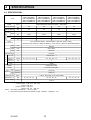
SPECIFICATIONS
4-1. SPECIFICATION
PMFY-P20VBM-E
PMFY-P20VBM-E1
PMFY-P20VBM-E#2
PMFY-P20VBM-ER3
PMFY-P20VBM-ER4
Item
PMFY-P40VBM-E
PMFY-P40VBM-E1
PMFY-P40VBM-E#2
PMFY-P40VBM-ER3
PMFY-P40VBM-ER4
Single phase 220V-230V-240V 50Hz / 220V 60Hz
Power
V Hz
Cooling capacity
kW
2.2
2.8
3.6
4.5
Heating capacity
kW
2.5
3.2
4.0
5.0
Electric characteristic
·
PMFY-P32VBM-E
PMFY-P32VBM-E1
PMFY-P32VBM-E#2
PMFY-P32VBM-ER3
PMFY-P32VBM-ER4
PMFY-P25VBM-E
PMFY-P25VBM-E1
PMFY-P25VBM-E#2
PMFY-P25VBM-ER3
PMFY-P25VBM-ER4
Cooling
kW
0.042
0.044
0.044
0.054
Heating
kW
0.042
0.044
0.044
0.054
Cooling
A
0.20
0.21
0.21
0.26
Heating
A
0.20
0.21
0.21
0.26
Input
Current
Exterior
(munsell symbol)
—
Unit : Galvanized sheets · Standard grilles : ABS resin acrylic coating
Munsell <0.98Y 8.99/0.63> (PMFY-P·VBM-E(1)) / <6.4Y 8.9/0.4> (PMFY-P·VBM-E#2/ER3/ER4)
Height
mm
230<30>
Dimensions Width
mm
812<1,000>
Depth
mm
395<470>
—
Cross fin
Fan × No
—
Line flow fan × 1
Air flow *3
G/min
External
static pressure
Fan motor
output
Pa
0
kW
0.028
Insulator
—
Polyethylene sheet
Air filter
—
PP honey comb fabric
:mm(in.)
12.7(1/2")
:mm(in.)
6.35(1/4")
Field drain pipe size
:mm
O.D.26 (PVC pipe VP-20 connectable)
Noise level *3
dB
Product weight
kg
F
a
n
Heat exchanger
Pipe
dimensions
Gas
side
Liquid
side
8.7 - 8.0 - 7.2 - 6.5
9.3 - 8.6 - 8.0 - 7.3
35 - 33 - 30 - 27
37 - 36 - 34 - 32
14<3.0>
Note 1. Rating conditions (JIS B 8615-1)
Cooling: Indoor: D.B. 27°C W.B. 19°C
outdoor: D.B. 35°C
Heating: Indoor: D.B. 20°C
outdoor: D.B. 7°C W.B. 6°C
Note 2. The number indicated in < > is for the grille.
*3. Air flow and the noise level are indicated as High – Medium1 – Medium2 – Low.
OC307E
12
10.7 - 9.7 - 8.7 - 7.7
39 - 37 - 35 - 33
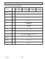
4-2. ELECTRIC PARTS SPECIFICATIONS
Service ref.
Symbol
Parts name
PMFY-P25VBM-E
PMFY-P32VBM-E
PMFY-P40VBM-E
PMFY-P20VBM-E
PMFY-P25VBM-E1
PMFY-P32VBM-E1
PMFY-P40VBM-E1
PMFY-P20VBM-E1
PMFY-P20VBM-E#2 PMFY-P25VBM-E#2 PMFY-P32VBM-E#2 PMFY-P40VBM-E#2
PMFY-P20VBM-ER3 PMFY-P25VBM-ER3 PMFY-P32VBM-ER3 PMFY-P40VBM-ER3
PMFY-P20VBM-ER4 PMFY-P25VBM-ER4 PMFY-P32VBM-ER4 PMFY-P40VBM-ER4
Room temperature
thermistor
TH21
Resistance 0/15k, 10/9.6k, 20/6.3k, 25/5.4k, 30/4.3k, 40/3.0k
Liquid pipe thermistor
TH22
Resistance 0/15k, 10/9.6k, 20/6.3k, 25/5.4k, 30/4.3k, 40/3.0k
Gas pipe thermistor
TH23
Resistance 0/15k, 10/9.6k, 20/6.3k, 25/5.4k, 30/4.3k, 40/3.0k
Fuse
(Indoor controller board)
FUSE
250V 6.3A
Fan motor
MF
DC Brushless Motor
8-pole OUTPUT 28W
PN0H28-MB
Vane motor
MV
MSFJC 20M23
12V/380
Drain pump
DP
PJV-1046
220-240V 50/60Hz
Drain sensor
DS
Linear expansion valve
LEV
Power supply
terminal block
TB2
(L, N, ) 330V 30A
Transmission
terminal block
TB5
(M1, M2, S) 250V 20A
MA-remote controller
terminal block
TB15
(1,2) 250V 10A
OC307E
Thermistor resistance 0/6k, 10/3.9k, 20/2.6k, 25/2.2k, 30/1.8k, 40/1.3k
DC12V Stepping motor drive, Port dimension :3.2
(0~2000pulse)
13
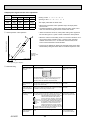
4-3. AIR CAPACITY TAKEN FROM OUTSIDE
PMFY-P·VBM-E series enables to take fresh air from outside. When taking fresh air, the duct fan is used.
The air capacity should be 20% or less of the air flow SPEC(Hi).
250
288.5
90
Unit : mm
4-W2.8
108
W100
22
W1
Fresh air intake hole
(Knockout)
Fresh air intake hole
(Knockout)
Service Ref.
Air flow (Hi) Air capacity from outside
PMFY-P20VBM-E
PMFY-P20VBM-E1
PMFY-P20VBM-E#2
PMFY-P20VBM-ER3
PMFY-P20VBM-ER4
8.7m³/min
Max 1.74m³/min
PMFY-P25VBM-E
PMFY-P25VBM-E1
PMFY-P25VBM-E#2
PMFY-P25VBM-ER3
PMFY-P25VBM-ER4
9.3m³/min
Max 1.86m³/min
PMFY-P32VBM-E
PMFY-P32VBM-E1
PMFY-P32VBM-E#2
PMFY-P32VBM-ER3
PMFY-P32VBM-ER4
9.3m³/min
Max 1.86m³/min
PMFY-P40VBM-E
PMFY-P40VBM-E1
PMFY-P40VBM-E#2
PMFY-P40VBM-ER3
PMFY-P40VBM-ER4
10.7m³/min
Max 2.14m³/min
Operation in conjunction with duct fan (Booster fan)
Whenever the indoor unit is operating, the duct fun
operates.
(1) Connect the optional multiple remote controller
adapter (PAC-SA88HA-E) to the connector CN51
on the indoor controller board.
(2) Drive the relay after connecting the 12V DC relay
between the Yellow and Orange connector lines.
( * ) Use a relay of 1W or smaller.
MB: Electromagnetic switch power relay for duct fan.
X: Auxiliary relay (12V DC LY-1F)
Q
E
C
A
Q
D
Q…Designed amount of fresh air intake
<m3/min>
A…Static pressure loss of fresh air
intake duct system with air flow
amount Q
<Pa>
B…Forced static pressure at air conditioner inlet with air flow amount Q
<Pa>
C…Static pressure of booster fan with
air flow amount Q
<Pa>
D…Static pressure loss increase amount
of fresh air intake duct system for air
flow amount Q
<Pa>
E…Static pressure of indoor unit with air
flow amount Q
<Pa>
Qa…Estimated amount of fresh air
intake without D
<m3/min>
~
Yellow
1
Connector (5P)
Red
Brown
MB
Orange
Multiple remote
controller adapter
PAC-SA88HA-E
Installation at site
Be sure to secure insulation
material by tape, etc.
Indoor controller board
Distance between indoor
controller board and relay
must be within 10m.
CN51
Characteristic diagram of fresh air taken capacity
50.0
0.0
2 intakes
1 intake
-50.0
-100.0
0.0
Q
Qa
OC307E
5
Indoor unit side
Static pressure (Pa)
A
0
C
Curve in the
right graphs
B
Duct characteristics
at site
CN51
on
indoor unit
board
Be sure to secure insulation
material by tape, etc.
Multiple remote
controller adapter
PAC-SA88HA-E
How to read curves
A
●
Green
14
0.5
1.5
1.0
Air flow (m3/min)
2.0
2.5
4-4. NOISE CRITERION CURVES
NOTCH SPL(dB)
35
High
Medium1
33
30
Medium2
Low
27
LINE
90
80
70
NC-70
60
NC-60
50
NC-50
40
NC-40
30
NC-30
20
10
NC-20
APPROXIMATE THRESHOLD OF HEARING
FOR CONTINUOUS NOISE
63
125
250
500
1000
2000
4000
8000
PMFY-P25/32VBM-E
PMFY-P25/32VBM-E1
PMFY-P25/32VBM-E#2
PMFY-P25/32VBM-ER3
PMFY-P25/32VBM-ER4
OCTAVE BAND SOUND PRESSURE LEVEL, dB (0 dB = 0.0002 μbar)
OCTAVE BAND SOUND PRESSURE LEVEL, dB (0 dB = 0.0002 μbar)
PMFY-P20VBM-E
PMFY-P20VBM-E1
PMFY-P20VBM-E#2
PMFY-P20VBM-ER3
PMFY-P20VBM-ER4
OCTAVE BAND SOUND PRESSURE LEVEL, dB (0 dB = 0.0002 μbar)
NOTCH SPL(dB)
39
High
Medium1
37
35
Medium2
Low
33
80
70
NC-70
60
NC-60
50
NC-50
40
NC-40
30
NC-30
20
10
APPROXIMATE
THRESHOLD OF
HEARING FOR
CONTINUOUS
NOISE
63
125
NC-20
250
500
1000
NC-70
1.5m
60
NC-60
MICROPHONE
50
NC-50
40
NC-40
30
NC-30
10
63
125
NC-20
250
500
1000
2000
4000
8000
BAND CENTER FREQUENCIES, Hz
OC307E
8000
UNIT
CEILING
APPROXIMATE
THRESHOLD OF
HEARING FOR
CONTINUOUS
NOISE
4000
LINE
80
20
2000
BAND CENTER FREQUENCIES, Hz
90
70
LINE
90
BAND CENTER FREQUENCIES, Hz
PMFY-P40VBM-E
PMFY-P40VBM-E1
PMFY-P40VBM-E#2
PMFY-P40VBM-ER3
PMFY-P40VBM-ER4
NOTCH SPL(dB)
High
37
Medium1
36
34
Medium2
Low
32
15
176
20
340 Suspension bolt pitch
Ceiling opening
430
Outer side of grille
470
Refrigerant
pipe(liquid)
O.D.W6.35
43
46
(96)
drain pan
812
759
Panel(grille)
580
1000 outer side of grille
Lower view
243
Front
(56)
W50
Air outlet(lower)
177
Outer line of grille
53
30
Terminal block for
MA remote controller
Electrical box
Center of unit
20
20
74.5
26
Knockout
Panel(grille)
Suspension bolt(M10 or W 3/8)
Installation space required around indoor unit
Terminal block for transmission
Right side
PVC pipe:VP-20[O.D.W26(1")]
O.D.W43
O.D.W6.35(1/4")
O.D.W12.7(1/2")
250
90
W100
4-W2.8 Burring hole
Details of fresh air intake hole
Pipe cover
Liquid pipe
Gas pipe
Terminal block for power supply
Drainage piping
Refrigerant
piping
Fresh air intake hole
288.5
mounting plate
PMFY-P32VBM-E
PMFY-P32VBM-E1
PMFY-P32VBM-E#2
PMFY-P32VBM-ER3
PMFY-P32VBM-ER4
Ceiling
Drain pan
panel
Same line
Left side
Ceiling panel
96
Refrigerant pipe(gas)
O.D.W12.7
395
302
254
Drainage pipe
141 PVC pipe:VP-20[I.D.W26]
20
198
(10)
17.5
28
28
45
45
230
(20)
17.5
1000 outer side of grille
960 ceiling opening
811 suspension bolt pitch
759
20
outer side of grille
20
74.5
26
40
60
247
69
Top
230
16
110
22
W1
235 or more
OC307E
PMFY-P25VBM-E
PMFY-P25VBM-E1
PMFY-P25VBM-E#2
PMFY-P25VBM-ER3
PMFY-P25VBM-ER4
110
PMFY-P20VBM-E
PMFY-P20VBM-E1
PMFY-P20VBM-E#2
PMFY-P20VBM-ER3
PMFY-P20VBM-ER4
470
108
5
OUTLINES AND DIMENSIONS
PMFY-P40VBM-E
PMFY-P40VBM-E1
PMFY-P40VBM-E#2
PMFY-P40VBM-ER3
PMFY-P40VBM-ER4
Unit : mm
6
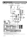
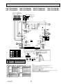
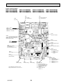
WIRING DIAGRAM
PMFY-P20VBM-E
PMFY-P25VBM-E
PMFY-P32VBM-E
FUSE BREAKER
PULL BOX (15A) (15A)
POWER SUPPLY
TO NEXT
~/N 220-230-240V 50Hz
INDOOR UNIT
220V 60Hz
TO OUTDOOR UNIT
BC CONTROLLER
REMOTE CONTROLLER
DC24-30V
TB5 M1 M2 (SHIELD)
TB2 L N
MF
PE
TO MA-REMOTE CONTROLLER
DC8.7-13V
BLU
BLU
5
1 2
ORN
ORN
RED
BLU
GRN/YLW
PMFY-P40VBM-E
I.B
CN3A
CN2M
(BLU) 1 2 (BLU) 1 2
REMOCON CN31
M-NET
(WHT)
DRAIN
LED2
CN29
(BLK)
GAS
CN21
(WHT)
LIQUID
CN20
(RED)
INTAKE
LED1
FAN
(WHT) 1 2 3 4 5 6
RED
BLU
FUSE
3
1
CND
(RED)
POWER
BLU
1
3
X1
CNP
(YLW)
D.U.M
X1
SW2
*See fig:1
SW3
SW5
220V
240V
(RED)
ADDRESS
CN43
SW1
1 2 3 4 5 6 7 8 9 10
SW12 SW11
0
0
10ths
DIGIT
1s
DIGIT
4
3
2
1
(RED)
ADDRESS
SWC
SW14 CN82
0
BRANCH
No.
8
7
6
5
4
3
2
1
(RED)
ADDRESS
CN42
1 2 3 4
TH23
2
1
TH22
TH21
BLU
BRN
ORN
YLW
RED
WHT
2
1
6
5
CN6V 4
(GRN)
VANE 3
2
1
LEV
BRN
RED
ORN
YLW
GRN
1
2
3 MV
4
5
CN25
2
1
(RED)
ADDRESS
CN81
CN27
1 2 3 4 5 6 7 8
4
8
[ LEGEND ]
NAME
SYMBOL
I.B
INDOOR CONTROLLER BOARD
CN25 CONNECTOR HUMIDIFIER
DAMPER
CN27
REMOTE SWITCH
CN32
HA TERMINAL-A
CN41
CENTRALLY CONTROL
CN51
REMOTE INDICATION
CN52
CAPACITY CODE
SW2 SWITCH
MODE SELECTION
SW3
MODEL SELECTION
SW4
ZNR VARISTOR
FUSE FUSE(6.3A/250V)
AUX.RELAY DRAIN PUMP
X1
TRANSFORMER
T
LED1 POWER SUPPLY(I.B)
LED2 POWER SUPPLY(I.B)
A.B
CIRCUIT BOARD
MODE SELECTION
SW1 SWITCH
VOLTAGE SELECTION
SW5
ADDRESS SETTING 1s DIGIT
SW11
ADDRESS SETTING 10ths DIGIT
SW12
BRANCH NO.
SW14
6
2
1
12345
A.B
(WHT)
REMOTE
SWITCH
CN32
1
3
2
1
2
1
0N
0FF
1 2 3 4 5 6 1 2 3 4 5 6 7 8 9 10
DS
CN60 4
(WHT)
LEV 3
SW4
0N
0FF
3
2
1
6
5
4
CN41
(WHT)
HA
1
5
CN51
(WHT)
CENTRALLY
CONTROL
1
CN52 5
(GRN)
REMOTE
INDICATION
1
ZNR
T
BLU
DP
TB15
<1>
SYMBOL
MF
MV
DP
DS
TB2
TB5
TB15
TH21
TH22
TH23
LEV
NAME
FAN MOTOR
VANE MOTOR
DRAIN PUMP
DRAIN SENSOR
TERMINAL POWER SUPPLY
BLOCK
TRANSMISSION
MA-REMOTE CONTROLLER
THERMISTOR ROOM TEMPERATURE DETECTION
(0/15k, 25/5.4k)
PIPE TEMPERATURE DETECTION/LIQUID
(0/15k, 25/5.4k)
PIPE TEMPERATURE DETECTION/GAS
(0/15k, 25/5.4k)
LINEAR EXPANSION VALVE
MODELS
P20VBM
SW2
0N
0FF
SW3
0N
0FF
123456
P25VBM
0N
0FF
P32VBM
0N
0FF
P40VBM
0N
0FF
123456 7 8 9 10
0N
0FF
123456
123456 7 8 9 10
0N
0FF
123456
123456 7 8 9 10
0N
0FF
123456
1 2 3 4 5 6 7 8 9 10
The black square (■) indicates a switch position.
LED on indoor board for service
Mark
Meaning
Function
Main power supply(Indoor unit:220-240V)
power on
Lamp is lit.
Power
supply
for
supply for MA-Remote controller
LED2 MA-Remote controller Power
on
Lamp is lit.
LED1 Main power supply
NOTES:
1. At servicing for outdoor unit, always follow the wiring diagram of outdoor unit.
2. In case of using MA-Remote controller, please connect to TB15. (Remote controller wire is non-polar.)
3. In case of using M-NET, please connect to TB5.(Transmission wire is non-polar.)
4. Symbol [S] of TB5 is the shield wire connection.
5. Symbols used in wiring diagram above are,
: terminal block,
: connector.
6. The setting of the SW2 dip switches differs in the capacity. For the detail, refer to the table above.
7. Please set the switch SW5 according to the power supply voltage. Set SW5 to 240V side when the power supply is 230 and 240 volts.
When the power supply is 220 volts, set SW5 to 220V side.
OC307E
17
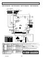
PMFY-P25VBM-E1
BREAKER
(15A)
POWER SUPPLY
~/N
220-240V 50Hz
220V 60Hz
MF
TO OUTDOOR UNIT
BC CONTROLLER
REMOTE CONTROLLER
DC24-30V
TO MA-REMOTE CONTROLLER
DC8.7-13V
TB5 M1 M2 S
(SHIELD)
I.B
6
3
1
CND
(RED)
POWER
BLU
BLU
1
BLU
3
CN51
(WHT)
CENTRALLY
CONTROL
A.B
SW3
SW2
12345
1 2 3 4 5 6 7 8 910
123456
1
CD
F
BRANCH
No.
4 5 6
NAME
INDOOR CONTROLLER BOARD
CONNECTOR HUMIDIFIER
DAMPER
REMOTE SWITCH
CENTRALLY CONTROL
REMOTE INDICATION
SWITCH
CAPACITY CODE
MODE SELECTION
MODEL SELECTOR
VARISTOR
FUSE (6.3A / 250V)
AUX.RELAY DRAIN PUMP
TRANSFORMER
POWER SUPPLY(I.B)
POWER SUPPLY(I.B)
FAN MOTOR
VANE MOTOR
DRAIN PUMP
DS
DRAIN SENSOR
OC307E
CN29 2
(BLK)
GAS 1
t°
TH23
CN21 2
(WHT)
LIQUID 1
t°
TH22
CN20 2
(RED)
INTAKE 1
t°
TH21
1
5
CN27
8
1
SYMBOL
TERMINAL
TB2
TB5
BLOCK
TB15
THERMISTOR
TH21
LEV
WHT
1
BRN
RED
ORN
M
YLW
1
CN25
M
YLW
CN6V
(GRN)
VANE
ON
OFF
RED
ORN
6
1
BRN
BLU
1
GRN
MV
5
2
1
2
1
<+1>
MODELS
SW2
P20VBM
ON
OFF
P25VBM
ON
OFF
P32VBM
ON
OFF
P40VBM
ON
OFF
123456
123456
123456
123456
SW3
ON
OFF
ON
OFF
ON
OFF
ON
OFF
1234567 8 910
1234567 8 910
123456 7 8 910
123456 7 8 910
The black square (■) indicates a
switch position.
8
8
[LEGEND]
SYMBOL
I.B
CN25
CN27
CN32
CN51
CN52
SW2
SW3
SW4
ZNR
FUSE
X1
T
LED1
LED2
MF
MV
DP
DS
5
4
(RED)
SW14 ADDRESS
E 01
CN82
AB
7 8
7 8
1s
DIGIT
t°
1
CN60
(WHT)
LEV
(RED)
ADDRESS
CN81
45
2 3
2 3
10ths
DIGIT
SWC
9 0 1
(RED)
ADDRESS
CN42
1
4
23
9 0 1
SW11
4 5 6
SW12
89
1 2 3 4 5 6 7 8 910
67
240V
SW1
CN52
(GRN)
REMOTE
INDICATION
SW4
(WHT)
REMOTE
SWITCH
CN32
3
1
3
6
X1
ON
OFF
4
(RED)
ADDRESS
CN43
1
CN31
(WHT)
DRAIN
U
CNP
(YLW)
D.U.M
*See fig :+1
220V
1
1
T
SW5
2 TB15
3 FUSE
RED
M
1~
DP
1
CN3A
(BLU)
2 1 REMOCON 3
CN2M
(BLU)
M-NET
LED2
LED1
FAN
(WHT)
BLU
MS
3~
BLU
BLU
GRN / YLW
RED
TB2 L N
PMFY-P40VBM-E1
ORN
FUSE
(15A)
PULL BOX
TO NEXT
INDOOR UNIT
PMFY-P32VBM-E1
ORN
PMFY-P20VBM-E1
NAME
POWER SUPPLY
TRANSMISSION
MA-REMOTE CONTROLLER
ROOM TEMP. DETECTION
(0/15k, 25/5.4k)
PIPE TEMP. DETECTION / LIQUID
TH22
(0/15k, 25/5.4k)
PIPE TEMP. DETECTION / GAS
TH23
(0/15k, 25/5.4k)
LEV
LINEAR EXPANSION VALVE
A.B
CIRCUIT BOARD
MODE SELECTION
SW1 SWITCH
VOLTAGE SELECTION
SW5
ADDRESS SETTING 1s DIGIT
SW11
ADDRESS SETTING 10ths DIGIT
SW12
SW14
BRANCH No.
LED on indoor board for service
Mark
Meaning
Function
Main power supply (Indoor unit:220-240V)
LED1
Main power supply
Power on Lamp is lit.
Power supply for
Power supply for MA-Remote controller
LED2
MA-Remote controller on Lamp is lit.
NOTES:
1. At servicing for outdoor unit, always follow the wiring diagram of outdoor unit.
2. In case of using MA-Remote controller, please connect to TB15.
(Remote controllerwire is non-polar.)
3. In case of using M-NET, please connect to TB5. (Transmission wire is non-polar.)
4. Symbol [S] of TB5 is the shield wire connection.
5. Symbols used in wiring diagram above are,
:terminal block,
:connector.
6. The setting of the SW2 dip switches differs in the capacity. For the detail, refer to
the table above.
7. Please set the switch SW5 according to the power supply voltage. Set SW5 to
240V side when the power supply is 230 and 240 volts. When the power supply is
220 volts, set SW5 to 220V side.
18
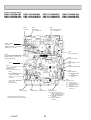
PMFY-P20VBM-E#2
PMFY-P20VBM-ER3
PMFY-P25VBM-E#2
PMFY-P25VBM-ER3
TO OUTDOOR UNIT
TO MA-REMOTE BC CONTROLLER
REMOTE CONTROLLER
CONTROLLER
DC24-30V
DC8.7-13V
FUSE
PULL BOX (15A)
TO NEXT
INDOOR
UNIT
TB15
TB5
S
(SHIELD)
TB2 L
N
1
3
I.B
BLK
5
CND (BLK)
FUSE
DSA
U
ZNR02
U
CNMF2
(WHT)
MF
MS
3~
ORN
ORN
5
BRN
RED
ORN
YLW
GRN
MV
7 5 3 1
BLU
BLU
X1
LED1
CN31 3
(WHT)
DRAIN 1
CNMF1
(WHT)
6
1 CN2M
(BLU)
2 M-NET
CN20
2
(RED)
INTAKE 1
LED2
1 CN3A
(BLU)
3 REMOCON
CN6V1
(GRN)
VANE
1
4
CN25 2
(WHT) 1
SWE
CN42
(RED)
CN41
(WHT)
HA
ON OFF
1 ADDRESS
1
3
CN32 (WHT)
REMOTE SWITCH
SW3
SW2
SW4
1 2 3 4 5 6 1 2 3 4 5 6 7 8 910 1 2 3 4 5
ON
OFF
123456 7 8 910
OC307E
SYMBOL
DS
TB2
TB5
TB15
TH21
1
CN44
(WHT)
LIQUID
/GAS
M
LEV
t°
TH21
t°
TH23
t°
TH22
1
90 1
10ths
DIGIT
SW11
90 1
SWC
1s
DIGIT
NAME
DRAIN SENSOR
TERMINAL POWER SUPPLY
TRANSMISSION
BLOCK
MA-REMOTE CONTROLLER
THERMISTOR ROOM TEMP. DETECTION
(0°C/15kΩ, 25°C/5.4kΩ)
PIPE TEMP. DETECTION / LIQUID
TH22
(0°C/15kΩ, 25°C/5.4kΩ)
PIPE TEMP. DETECTION / GAS
TH23
(0°C/15kΩ, 25°C/5.4kΩ)
LEV
LINEAR EXPANSION VALVE
A.B
CIRCUIT BOARD
MODE SELECTION
SW1 SWITCH
VOLTAGE SELECTION
SW5
ADDRESS SETTING 1s DIGIT
SW11
ADDRESS SETTING 10ths DIGIT
SW12
SW14
BRANCH No.
8
(RED)
SW14 ADDRESS
F0 1 2
CN82
E
3456
NAME
INDOOR CONTROLLER BOARD
CONNECTOR HUMIDIFIER
DAMPER
REMOTE SWITCH
CENTRALLY CONTROL
REMOTE INDICATION
SWITCH
CAPACITY CORD
MODE SELECTION
MODEL SELECTOR
DRAIN UP MACHINE(TEST MODE)
VARISTOR
FUSE (T6.3AL 250V)
AUX.RELAY DRAIN PUMP
POWER SUPPLY (I.B)
POWER SUPPLY (I.B)
FAN MOTOR
VANE MOTOR
DRAIN PUMP
SW12
2 3
[LEGEND]
SYMBOL
I.B
CN25
CN27
CN32
CN51
CN52
SW2
SW3
SW4
SWE
ZNR
FUSE
X1
LED1
LED2
MF
MV
DP
1 2 3 4 5 6 7 8 910
2 3
LED on indoor board for service
Mark
Meaning
Function
Main power supply (Indoor unit:220-240V)
Main power supply
LED1
Power on → Iamp is lit
Power supply for
Power supply for MA-Remote controller
LED2 MA-Remote controller on → Iamp is lit
240V
SW1
123456 7 8 910
The black square (■) indicates a switch position.
4
(RED)
ADDRESS
CN43
1
SW5
220V
BCD
123456
ON
OFF
A.B
1234567 8 910
7 8
P40VBM
ON
OFF
123456
1234567 8 910
7 8
ON
OFF
123456
ON
OFF
5 6
P32VBM
123456
4
ON
OFF
5 6
P25VBM
4
BRN
RED
BLU
ORN
YLW
WHT
DS
4
4
P20VBM
1
1
t°
8
SW3
ON
OFF
789A
SW2
ON
OFF
2
1
CN27
(RED)
4
CN51 (WHT) 5
CENTRALLY
CONTROL
CN52 5
ADDRESS
(GRN)
CN81 (RED)
1
8
REMOTE
INDICATION
1
<1>
MODELS
M
1~
DP
CNP
(YLW)
D.U.M
CN60
(WHT)
LEV
6
*See fig : 1
2 1
DC311
~339V
ZNR01
1
3
5
BLU
BLU
M
8 6 4 2
PMFY-P40VBM-E#2
PMFY-P40VBM-ER3
BREAKER
(15A)
POWER SUPPLY
~/N
220-240V 50Hz
220V 60Hz
GRN/YLW
M1 M2
BLU
2
RED
1
PMFY-P32VBM-E#2
PMFY-P32VBM-ER3
BRANCH
No.
NOTES:
1
1.At servicing for outdoor unit,always follow the wiring diagram of outdoor unit.
2.In case of using MA-Remote controller, please connect to TB15.
(Remote controller wire is non-polar.)
3.In case of using M-NET, please connect to TB5. (Transmission line is non-polar.)
4.Symbol [S] of TB5 is the shield wire connection.
5.Symbols used in wiring diagram above are,
: terminal block,
:connecter.
6.The setting of the SW2 dip switches differs in the capacity. For the detail, refer to the table below.
7.Please set the switch SW5 according to the power supply voltage.
Set SW5 to 240V side when the power supply is 230 and 240 volts.
When the power supply is 220 volts, set SW5 to 220V side.
19
PMFY-P20VBM-ER4
PMFY-P25VBM-ER4
TO OUTDOOR UNIT
TO MA-REMOTE BC CONTROLLER
REMOTE CONTROLLER
CONTROLLER
DC24-30V
DC8.7-13V
FUSE
PULL BOX (15A)
TO NEXT
INDOOR
UNIT
TB15
TB5
S
(SHIELD)
TB2 L
N
1
3
I.B
BLK
CND (BLK)
5 FUSE
X1
1
BLU
3
BLU
8 6 4
5
MV
LED1
CN31 3
(WHT)
DRAIN 1
CNMF1
(WHT)
6
CN60
(WHT)
LEV
5
BLU
BLU
1 CN2M
(BLU)
2 M-NET
ORN
1 CN3A
(BLU)
3 REMOCON
ORN
M
1
2
7 5 3 1
MF
MS
3~
2
GRN
YLW
ORN
RED
BRN
LED2
CN6V1
(GRN)
VANE
1
4
1
5
CN25 2
(WHT) 1
SWE
CN42
(RED)
CN41
(WHT)
ON OFF
1 ADDRESS
1
3
CN32 (WHT)
REMOTE SWITCH
SW3
SW2
6
*See fig : *1
CN20
2
(RED)
INTAKE 1
CN105
(RED)
SW4
1 2 3 4 5 6 1 2 3 4 5 6 7 8 910 1 2 3 4 5
M
1~
DP
CNP
(YLW)
D.U.M
CNMF2
(WHT)
PMFY-P40VBM-ER4
BREAKER
(15A)
POWER SUPPLY
~/N
220-240V 50Hz
220V 60Hz
GRN/YLW
M1 M2
BLU
2
RED
1
PMFY-P32VBM-ER4
2
1
CN27
(RED)
4
1
CN51 (WHT) 5
CENTRALLY
CONTROL
CN52 5
ADDRESS
(GRN)
CN81 (RED)
1
8
REMOTE
INDICATION
1
1
4
1
CN44
(WHT)
LIQUID
/GAS
t°
BRN
RED
BLU
ORN
YLW
WHT
DS
M
LEV
t°
TH21
t°
TH23
t°
TH22
1
8
4
The black square (■) indicates a
switch position. <*1>
123456
123456 7 8 910
123456 7 8 910
[LEGEND]
SYMBOL
NAME
I.B
INDOOR CONTROLLER BOARD
CN25 CONNECTOR HUMIDIFIER
CN27
DAMPER
CN32
REMOTE SWITCH
CN51
CENTRALLY CONTROL
CN52
REMOTE INDICATION
CN105
IT TERMINAL
CAPACITY CORD
SW2 SWITCH
MODE SELECTION
SW3
MODEL SELECTOR
SW4
SWE
DRAIN UP MACHINE (TEST MODE)
FUSE FUSE (T6.3AL 250V)
X1
AUX.RELAY DRAIN PUMP
LED1 POWER SUPPLY (I.B)
LED2 POWER SUPPLY (I.B)
MF
FAN MOTOR
MV
VANE MOTOR
DP
DRAIN PUMP
OC307E
SW12
9 0 1
10ths
DIGIT
SW11
SWC
9 0 1
1s
DIGIT
2
1
(RED)
SW14 ADDRESS
F 012
CN82
D
BC E
ON
OFF
1 2 3 4 5 6 7 8 910
7 8
123456
1234567 8 910
7 8
ON
OFF
ON
OFF
4 5 6
P40VBM
ON
OFF
8
3456
P32VBM
ON
OFF
123456
2 3
ON
OFF
SW1
1234567 8 910
2 3
P25VBM
123456
SW3
ON
OFF
240V
4 5 6
SW2
ON
OFF
4
(RED)
ADDRESS
CN43
1
SW5
220V
789A
MODELS
P20VBM
A.B
BRANCH
No.
1
NOTES:
SYMBOL
DS
TB2
TB5
TB15
TH21
NAME
DRAIN SENSOR
TERMINAL POWER SUPPLY
TRANSMISSION
BLOCK
MA-REMOTE CONTROLLER
THERMISTOR ROOM TEMP. DETECTION
(0°C/15kΩ, 25°C/5.4kΩ)
PIPE TEMP. DETECTION / LIQUID
TH22
(0°C/15kΩ, 25°C/5.4kΩ)
PIPE TEMP. DETECTION / GAS
TH23
(0°C/15kΩ, 25°C/5.4kΩ)
LEV
LINEAR EXPANSION VALVE
A.B
CIRCUIT BOARD
SW1 SWITCH
MODE SELECTION
SW5
VOLTAGE SELECTION
SW11
ADDRESS SETTING 1s DIGIT
SW12
ADDRESS SETTING 10ths DIGIT
SW14
BRANCH No.
20
1. At servicing for outdoor unit,always follow the wiring diagram of outdoor unit.
2. In case of using MA-Remote controller, please connect to TB15.
(Remote controller wire is non-polar.)
3. In case of using M-NET, please connect to TB5. (Transmission line is non-polar.)
4. Symbol [S] of TB5 is the shield wire connection.
5. Symbols used in wiring diagram above are,
: terminal block,
:connecter.
6. The setting of the SW2 dip switches differs in the capacity. For the detail,
refer to the table below.
7. Please set the switch SW5 according to the power supply voltage.
Set SW5 to 240V side when the power supply is 230 and 240 volts.
When the power supply is 220 volts, set SW5 to 220V side.
LED on indoor board for service
Mark
Meaning
Function
Main power supply (Indoor unit:220-240V)
Main power supply
LED1
Power on → Iamp is lit
Power supply for
Power supply for MA-Remote controller
LED2 MA-Remote controller on → Iamp is lit
7
REFRIGERANT SYSTEM DIAGRAM
PMFY-P20VBM-E
PMFY-P20VBM-E1
PMFY-P20VBM-E#2
PMFY-P20VBM-ER3
PMFY-P20VBM-ER4
PMFY-P25VBM-E
PMFY-P25VBM-E1
PMFY-P25VBM-E#2
PMFY-P25VBM-ER3
PMFY-P25VBM-ER4
PMFY-P32VBM-E
PMFY-P32VBM-E1
PMFY-P32VBM-E#2
PMFY-P32VBM-ER3
PMFY-P32VBM-ER4
Gas pipe
temperature
thermistor TH23
PMFY-P40VBM-E
PMFY-P40VBM-E1
PMFY-P40VBM-E#2
PMFY-P40VBM-ER3
PMFY-P40VBM-ER4
Strainer (#50mesh)
Gas pipe
Liquid pipe
temperature
thermistor TH22
Flare connection
+1
+2
Liquid pipe
Heat exchanger
Strainer (#100mesh)
Linear expansion valve
Strainer (#100mesh)
Room temperature thermistor TH21
Service Ref.
Item
Unit: mm (inch)
PMFY-P20, P25, P32, P40VBM-E
PMFY-P20, P25, P32, P40VBM-E1
PMFY-P20, P25, P32, P40VBM-E#2
PMFY-P20, P25, P32, P40VBM-ER3
PMFY-P20, P25, P32, P40VBM-ER4
Gas pipe
:12.7(1/2")
Liquid pipe
:6.35(1/4")
PMFY-P20, P25VBM-E
PMFY-P20, P25VBM-E1
PMFY-P20, P25VBM-E#2
PMFY-P20, P25VBM-ER3
PMFY-P20, P25VBM-ER4
Unit: mm
PMFY-P32, P40VBM-E
PMFY-P32, P40VBM-E1
PMFY-P32, P40VBM-E#2
PMFY-P32, P40VBM-ER3
PMFY-P32, P40VBM-ER4
Capillary tube +1 O.D.:4.6 % I.D.:3.4 % 1200 O.D.:3.6 % I.D.:2.4 % 1200
Capillary tube +2
OC307E
O.D.:3.6 % I.D.:2.4 % 180
21
8
TROUBLE SHOOTING
8-1. HOW TO CHECK
PMFY-P20VBM-E
PMFY-P20VBM-E1
PMFY-P20VBM-E#2
PMFY-P20VBM-ER3
PMFY-P20VBM-ER4
THE PARTS
PMFY-P25VBM-E
PMFY-P25VBM-E1
PMFY-P25VBM-E#2
PMFY-P25VBM-ER3
PMFY-P25VBM-ER4
PMFY-P32VBM-E
PMFY-P32VBM-E1
PMFY-P32VBM-E#2
PMFY-P32VBM-ER3
PMFY-P32VBM-ER4
Parts name
Check points
Room temperature
thermistor
(TH21)
Liquid pipe temperature
thermistor
(TH22)
Gas pipe temperature
thermistor
(TH23)
Disconnect the connector then measure the resistance with a tester.
(At the ambient temperature 10 - 30)
Vane motor (MV)
Measure the resistance between the terminals with a tester.
(At the ambient temperature 20 - 30)
Yellow Orange
Linear expansion
valve(LEV)
4.3k~9.6k
Open or short
Brown — Red
Green
Abnormal
Refer to the next page for the details.
Normal
Abnormal
380 $7%
Open or short
Brown — Yellow
Red Brown M
Normal
Connector
MV
PMFY-P40VBM-E
PMFY-P40VBM-E1
PMFY-P40VBM-E#2
PMFY-P40VBM-ER3
PMFY-P40VBM-ER4
Blue
Brown
Yellow
Brown — Orange
Brown — Green
Disconnect the connector then measure the resistance valve with a tester.
Refer to the next page for a detail.
Normal
(1)-(5)
White-Red
Abnormal
(2)-(6)
(3)-(5)
Yellow-Brown Orange-Red
(4)-(6)
Blue-Brown
200 $10%
Orange
Red
Open or short
Refer to the next
page for the details.
White
Drain pump (DP)
Blue
Blue
Measure the resistance between the terminals with a tester.
(At the ambient temperature 20)
1
Normal
Abnormal
3
400~480
Open or short
Drain sensor (DS)
1
2
3
OC307E
Measure the resistance after 3 minutes have passed since the power supply was intercepted.
(At the ambient temperature 0 - 60)
Normal
Abnormal
0.6k~6.0k
Open or short
22
Refer to the next page for the details.
<Thermistor Characteristic graph>
< Thermistor for lower temperature >
Thermistor for
lower temperature
Room temperature thermistor (TH21)
Liquid pipe temperature thermistor (TH22)
Gas pipe temperature thermistor (TH23)
Rt=15exp { 3480(
0: :
10: :
20: :
25: :
30: :
40: :
1
273+t
40
Resistance (k)
Thermistor R0=15k' ± 3%
Fixed number of B=3480 ± 2%
50
1 )}
273
15k'
9.6k'
6.3k'
5.4k'
4.3k'
3.0k'
30
20
10
0
Thermistor for
lower temperature
10
Drain sensor (DS)
-10
0
10
20
30
Temperature ()
40
50
< Thermistor for drain sensor >
9
8
Resistance (k)
Thermistor R0=6.0k' ± 3%
Fixed number of B=3390 ± 2%
Rt=6exp { 3390( 1
273+t
0: :
6 k'
10: : 3.9k'
20: : 2.6k'
25: : 2.2k'
30: : 1.8k'
40: : 1.3k'
-20
1 )}
273
7
6
5
4
3
2
1
0
-20
0
20
40
60
Temperature ()
80
Linear expansion valve
1 Operation summary of the linear expansion valve
• Linear expansion valve open/close through stepping motor after receiving the pulse signal from the indoor controller board.
• Valve position can be changed in proportion to the number of pulse signal.
<Connection between the indoor controller board and the linear expansion valve>
Controller board
DC12V
Linear expansion valve
Brown
6
Red
5
4
Blue
M
Brown
:4
Blue
4
:4
6
Yellow
Orange
3
:3
2
:3
5
:2
Yellow
2
:2
:1
White
1
:1
1
White Red
3
Orange
Drive circuit
Connector (CN60)
Note : Since the number of the connector at the controller board side and the relay connector are different, follow the colour of
the lead wire.
OC307E
23
<Output pulse signal and the valve operation>
Output
Output
(Phase)
1
2
3
4
{1
{2
{3
{4
ON
ON
OFF
OFF
OFF
ON
ON
OFF
OFF
OFF
ON
ON
ON
OFF
OFF
ON
2 Linear expansion valve operation
The output pulse shifts in above order.
• When linear expansion valve operation stops, all output phase
become OFF.
• At phase interruption or when phase does not shift in order, motor
does not rotate smoothly and motor will lock and vibrate.
• When the switch is turned on, 2200 pulse closing valve signal will
be send till it goes to A point in order to define the valve position.
C
D
Valve position (capacity)
Closing a valve : 1 → 2 → 3 → 4 → 1
Opening a valve : 4 → 3 → 2 → 1 → 4
• When the valve move smoothly, there is no sound or vibration occurring from the linear expansion valve : however, when the pulse
number moves from E to A or when the valve is locked, more
sound can be heard than normal situation.
• Sound can be detected by placing the ear against the screw driver
handle while putting the screw driver to the linear expansion valve.
Close
Open
2000 pulse
Opening a valve
all the way
A
E
Pulse number
B
Extra tightening (80~100pulse)
3 Troubleshooting
Symptom
Check points
Countermeasures
Exchange the indoor controller board at drive circuit
failure.
Operation circuit
failure of the micro
processor
Disconnect the connector on the controller board, then connect LED for checking.
6
5
4
3
2
1
1k LED
Pulse signal will be sent out for 10 seconds as soon as the
main switch is turned on. If there is LED with lights on or
lights off, it means the operation circuit is abnormal.
Linear expansion
valve mechanism is
locked.
Motor will idle and make ticking noise when motor is operated Exchange the linear expanwhile the linear expansion valve is locked. This ticking sound sion valve.
is the sign of the abnormality.
Short or breakage
Measure the resistance between the each coil (red-white, red- Exchange the linear expanof the motor coil of
orange, brown-yellow, brown-blue) with a tester. It is normal if sion valve.
the linear expansion the resistance is in the range of 200 " ± 10%.
valve
Valve does not close To check the linear expansion valve, operate the indoor unit If large amount of refrigercompletely (thermis- in fan mode and at the same time operate other indoor units ant is leaked, exchange
tor leaking).
in cooling mode, then check the pipe temperature <liquid
the linear expansion valve.
pipe temperature> of the indoor unit by the
outdoor multi controller board operation
monitor. During fan operation, linear expansion valve is closed completely and if there
Thermistor
(Liquid pipe) are some leaking, detecting temperature of
the thermistor will go lower. If the detected
Linear
expansion
temperature is much lower than the temvalve
perature indicated in the remote controller,
it means the valve is not closed all the way.
It is not necessary to exchange the linear expansion valve, if
the leakage is small and not making any trouble.
Wrong connection
of the connector or
contact failure
OC307E
Check the color of lead wire and missing terminal of the con- Disconnect the connector
nector.
at the controller board,
then check the continuity.
24
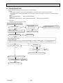
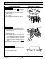
8-2. TROUBLESHOOTING
Check method of indoor fan motor (fan motor / controller board)
Notes
· High voltage is applied to the connecter (FAN)(CNMF1, 2) for the fan motor. Pay attention to the service.
· Do not pull out the connector (FAN)(CNMF1, 2) for the motor with the power supply on, doing so may result in damage
to the board.
(FAN)
PMFY-P20/25/32/40VBM-E
PMFY-P20/25/32/40VBM-E1
(CNMF1, 2)
PMFY-P20/25/32/40VBM-E#2 PMFY-P20/25/32/40VBM-ER3 PMFY-P20/25/32/40VBM-ER4
Self check
Symptom : The indoor fan can not rotate.
Indoor controller board fuse check
Is the fuse normal?
Is the resistance
between the terminals of
drain pump normal?
No
Yes
Replace the fan motor.
Replace the indoor controller board.
No
Wiring contact check
Contact of fan motor connector (FAN) (CNMF1,2)
Is there contact failure?
Yes
Replace the drain pump.
Yes
Wiring recovery
No
Turn ON the power supply.
Power supply check
Check the voltage of the indoor controller board with the connector (FAN) (CNMF1, 2)connected to the board.
Approx. 310~340V DC between the connecter < (FAN) (+) and (–) > < (CNMF1)
(+) and (CNMF2)
(-) >
Yes
Is the voltage normal?
Replace
the fan motor.
No
Check the operation
OK
NG
Replace the the indoor controler board.
Replace the indoor controller board.
Check the operation
OK
END
NG
Replace the fan motor.
OC307E
25
END
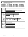
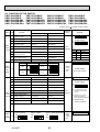
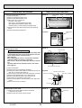
8-3. FUNCTION OF DIP SWITCH
PMFY-P20VBM-E
PMFY-P25VBM-E
PMFY-P25VBM-E1
PMFY-P20VBM-E1
PMFY-P20VBM-E#2 PMFY-P25VBM-E#2
PMFY-P20VBM-ER3 PMFY-P25VBM-ER3
PMFY-P20VBM-ER4 PMFY-P25VBM-ER4
PMFY-P32VBM-E
PMFY-P32VBM-E1
PMFY-P32VBM-E#2
PMFY-P32VBM-ER3
PMFY-P32VBM-ER4
PMFY-P40VBM-E
PMFY-P40VBM-E1
PMFY-P40VBM-E#2
PMFY-P40VBM-ER3
PMFY-P40VBM-ER4
The black square (
Switch Pole
SW1
Mode
Selection
Operation by switch
Function
ON
1
Thermistor <Room temperature
detection> position
Bult-in remote controller
Indoor unit
2
Filter clogging detection
Provided
Not provided
3
Filter cleaning sign
2,500h
100h
4
Fresh air intake
Effective
Not effective
5
Switching remote display
Thermo ON signal indication
Fan output indication
6
Humidifier control
Fan operation at Heating mode
Thermo On operation at heating mode
7
Air flow at
Low *1
Extra low *1
8
Heat thermo OFF
Setting air flow
Depends on SW1-7
9
Auto restart function
Effective
Not effective
Power source ON/OFF
Effective
Not effective
10
Capacity
SW2
Capacity
1~6
code
setting
SW3
Function
Selection
OFF
P20
P25
SW 2
ON
OFF
ON
OFF
Capacity
P32
1 2 3 4 5 6
P40
1 2 3 4 5 6
Effective
timing
ON
OFF
Remarks
Address board
<Initial setting>
ON
OFF
Under
suspension
1 2 3 4 5 6 7 8 9 10
*1
SW 1-7 SW 1-8 SW 1-8
OFF
OFF
Extra low
ON
OFF
Low
OFF
ON
Setting air flow
ON
ON
stop
Indoor controller board
SW 2
ON
OFF
) indicates a switch position.
1 2 3 4 5 6
Before
power
supply
ON
<Initial setting>
Set for each capacity.
1 2 3 4 5 6
1
Heat pump / Cool only
Cooling only
Heat pump
2
Louver
Available
Not available
Set while the unit is off.
3
Vane
Available
Not available
<Initial setting>
4
Vane swing function
Available
Not available
5
Vane horizontal angle
Second setting *4
First setting
6
Vane cooling limit angle setting *2 Horizontal angle
Down B, C
7
Indoor linear expansion
valve opening change
Effective
Not effective
8
Heating 4deg. up
Not effective
Effective
9
Target superheat setting *3
—
—
10
Target sub cool setting *3
—
—
SW4
Unit 1~5
Selection
Indoor controller board
PMFY-P·VBM-E
PMFY-P·VBM-E1
PMFY-P·VBM-E#2/ER3/ER4
ON
OFF
ON
OFF
ON
OFF
1 2 3 4 5
OC307E
1 2 3 4 5
1 2 3 4 5
26
ON
OFF
1 2 3 4 5 6 7 8 9 10
*2 At cooling mode, each
Under
suspension
angle can be used only
1 hour.
*3 Please do not change
SW3-9 and SW3-10.
See 6. WIRING DIAGRAM.
*4 Second setting
means first setting.
Before
power
supply
ON
Indoor controller board
The black square (
Switch Pole
Effective
timing
Remarks
1
<Initial setting>
SW12
SW11
23
90 1
23
90 1
78
45 6
10
How to set addresses
Example : If address is “3”, remain SW12
(for over 10) at “0”, and match SW11 (for 1 to 9)
with “3”.
78
90 1
78
78
SW11
45 6
90 1
45 6
SW12
23
Rotary switch
Address board
23
45 6
SW11
1s digit
address
setting
SW12
10ths digit
address
setting
Operation by switch
) indicates a switch position.
<Initial setting>
SW14
F01
45 6
Before
power
supply
ON
23
How to set branch numbers SW14 (Series R2 only)
Match the indoor unit’s refrigerant pipe with
the BC controller’s end connection number.
Remain other than series R2 at “0”.
CDE
AB
45 6
CDE
AB
F01
789
SW14
23
789
SW14
Branch
No.
setting
Rotary switch
Address board
Address board
SW5
Voltage
Selection
220V
2
OC307E
240V If the unit is used at the 230V or 240V area,
set the voltage to 240V.
If the unit is used at the 220V, set the voltage
to 220V.
27
<Initial setting>
220V
240V
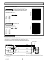
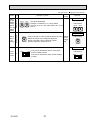
8-4. TEST POINT DIAGRAM
8-4-1. Indoor controller board
PMFY-P20VBM-E
PMFY-P20VBM-E1
PMFY-P25VBM-E
PMFY-P25VBM-E1
SW2
Capacity setting
SW3
Mode selection
PMFY-P32VBM-E
PMFY-P32VBM-E1
SW4
Model selection
PMFY-P40VBM-E
PMFY-P40VBM-E1
CN32
Connector
(Remote switch)
CN27
Damper
CN25
Humidifier
CNP
Drain pump
output (DP)
Between 1 to 3
220-240V AC
CN6V
Vane motor output
(MV)
CN52
Remote indicator
1-2: Status lamp 12VDC (1 : +)
Fan motor output (SW1-5 OFF)
Thermostat ON (SW1-5 ON)
1-3: Cooling/Dry status lamp
12VDC (1 : +)
1-4: Heating status lamp
12VDC (1 : +)
CND
Power supply for
indoor controller board
Between 1 to 3
220-240V AC
CN51
Centrally control
1-2 : Control signal
12VDC pulse input (1 : +)
3-4 : Operation indicator
12VDC (3 : +)
3-5 : Malfunction indicator
12VDC (3 : +)
FUSE
6.3A 250V
CN41
Connector
(HA terminal-A)
FAN
Fan motor output (MF)
CN60
Linear expansion valve
output (LEV)
CN20
Room temperature
thermistor (TH21)
CN21
Pipe temperature
thermistor/Liquid (TH22)
CN29
Pipe temperature
thermistor/Gas (TH23)
CN31
Drain sensor (DS)
LED2
Power supply for
MA-Remote controller
CN2M
Connect to the terminal block (TB5)
(M-NET transmission connecting wire)
24-30V DC (non-polar)
CN3A
Connect to the terminal block (TB15)
(MA-Remote controller connecting wire)
Between 1 to 3 8.7-13V DC (Pin1 (+))
OC307E
28
LED1
Main power supply
(Indoor unit : 220-240V)
Indoor controller board
PMFY-P20VBM-E#2
PMFY-P20VBM-ER3
PMFY-P20VBM-ER4
PMFY-P25VBM-E#2
PMFY-P25VBM-ER3
PMFY-P25VBM-ER4
FUSE
6.3A 250V
PMFY-P32VBM-E#2
PMFY-P32VBM-ER3
PMFY-P32VBM-ER4
CND
Power supply
1-3 : 220-240V AC
PMFY-P40VBM-E#2
PMFY-P40VBM-ER3
PMFY-P40VBM-ER4
CNP
Drain pump output (DP)
1-3 : 220-240V AC
CNMF1, CNMF2
FAN motor
CNMF11-CNMF21 : 310-340V DC
CNMF27-1 : 0-15V DC
LED1
Main power supply
CN2M
Connect to the terminal block TB5
(M-NET transmission connecting wire)
24-30V DC (non-polar)
CN31
Drain sensor (DS)
LED2
Power supply for
MA-Remote controller
CN60
Linear expansion valve
(LEV)
CN3A
MA-Remote controller
connecting wire
1-3 8.7-13V DC (Pin 1 (+))
CN20
Room thermistor (TH21)
CN44
Pipe temperature
1-2: thermistor/Liquid
(TH22)
3-4: thermistor/Gas
(TH23)
CN6V1
Vane motor
CN32
Connector
(Remote switch)
SW2
Capacity setting
SW3
Function setting
SW4
Model setting
The voltage range of DC12V in this
page is between DC11.5 V to DC 13.7 V.
OC307E
29
CN52
Remote indicator
1-2: Status lamp 12VDC (1 : +)
Fan motor output (SW1-5 OFF)
Thermostat ON (SW1-5 ON)
1-3: Cooling/Dry status lamp
12VDC (1 : +)
1-4: Heating status lamp
12VDC (1 : +)
CN51
Centrally control
1-2 : Control signal
12VDC pulse input (1 : +)
3-4 : Operation indicator
12VDC (3 : +)
3-5 : Malfunction indicator
12VDC (3 : +)
Indoor controller board
PMFY-P20VBM-E#2
PMFY-P20VBM-ER3
PMFY-P20VBM-ER4
PMFY-P25VBM-E#2
PMFY-P25VBM-ER3
PMFY-P25VBM-ER4
FUSE
6.3A 250V
PMFY-P32VBM-E#2
PMFY-P32VBM-ER3
PMFY-P32VBM-ER4
CND
Power supply
1-3 : 220-240V AC
PMFY-P40VBM-E#2
PMFY-P40VBM-ER3
PMFY-P40VBM-ER4
CNP
Drain pump output (DP)
1-3 : 220-240V AC
CNMF1, CNMF2
FAN motor
CNMF11-CNMF21 : 310-340V DC
CNMF27-1 : 0-15V DC
LED1
Main power supply
CN2M
Connect to the terminal block TB5
(M-NET transmission connecting wire)
24-30V DC (non-polar)
CN31
Drain sensor (DS)
CN60
Linear expansion valve
(LEV)
CN105
CN20
Room thermistor (TH21)
CN3A
MA-Remote controller
connecting wire
1-3 8.7-13V DC (Pin 1 (+))
CN44
Pipe temperature
1-2: thermistor/Liquid
(TH22)
3-4: thermistor/Gas
(TH23)
LED2
Power supply for
MA-Remote controller
CN6V1
Vane motor
CN51
Centrally control
1-2 : Control signal
12VDC pulse input (1 : +)
3-4 : Operation indicator
12VDC (3 : +)
3-5 : Malfunction indicator
12VDC (3 : +)
CN32
Connector
(Remote switch)
SW2
Capacity setting
SW3
Function setting
SW4
Model setting
The voltage range of DC12V in this
page is between DC11.5 V to DC 13.7 V.
OC307E
30
CN52
Remote indicator
1-2: Status lamp 12VDC (1 : +)
Fan motor output (SW1-5 OFF)
Thermostat ON (SW1-5 ON)
1-3: Cooling/Dry status lamp
12VDC (1 : +)
1-4: Heating status lamp
12VDC (1 : +)
8-4-2. Address board
PMFY-P20VBM-E
PMFY-P20VBM-E1
PMFY-P20VBM-E#2
PMFY-P20VBM-ER3
PMFY-P20VBM-ER4
PMFY-P25VBM-E
PMFY-P25VBM-E1
PMFY-P25VBM-E#2
PMFY-P25VBM-ER3
PMFY-P25VBM-ER4
PMFY-P32VBM-E
PMFY-P32VBM-E1
PMFY-P32VBM-E#2
PMFY-P32VBM-ER3
PMFY-P32VBM-ER4
PMFY-P40VBM-E
PMFY-P40VBM-E1
PMFY-P40VBM-E#2
PMFY-P40VBM-ER3
PMFY-P40VBM-ER4
SW5
Voltage selector
SW1
Function setting
SW12
Address setting
10ths DIGIT
OC307E
SW11
Address setting
1s DIGIT
31
SW14
Branch No.
9
DISASSEMBLY PROCEDURE
PMFY-P20VBM-E
PMFY-P20VBM-E1
PMFY-P20VBM-E#2
PMFY-P20VBM-ER3
PMFY-P20VBM-ER4
PMFY-P25VBM-E
PMFY-P25VBM-E1
PMFY-P25VBM-E#2
PMFY-P25VBM-ER3
PMFY-P25VBM-ER4
PMFY-P32VBM-E
PMFY-P32VBM-E1
PMFY-P32VBM-E#2
PMFY-P32VBM-ER3
PMFY-P32VBM-ER4
PMFY-P40VBM-E
PMFY-P40VBM-E1
PMFY-P40VBM-E#2
PMFY-P40VBM-ER3
PMFY-P40VBM-ER4
Be careful when removing heavy parts.
OPERATING PROCEDURE
PHOTOS&ILLUSTRATIONS
Photo 1
1. Removing the grille
Opening the air intake grille
Air intake grille
Air outlet
grille
(1) Press the PUSH of the air intake grille. (See Figure 1)
(2) Put your fingers on the both ends of nut of the air intake
grille and put it down after the grille clicked.
Nozzle
Removing the air intake grille
(1) Press the PUSH of the air intake grille, and pull down the
both ends of nut with your fingers after the grille clicked.
(See Figure 1)
(2) Pull out the handle of air intake grille strongly toward you.
(See Figure 2)
(3) Draw the string of the air intake grille to prevent the air
intake grille from dropping. (See Figure 3)
Air filter
PUSH
Figure 1
Checks before setting the grille in place
(1) Before installing the grille, make sure the indoor unit is
square with the ceiling opening (or parallel to the angle
between the wall and the ceiling).
(2) Check that the 4 points where the grille will be secured are
in contact with the ceiling surface.
(3) Check that the insulation for the refrigerant pipes, drainage pipes, etc. is in place and that wiring connections and
arrangements are complete.
Figure 4
Figure 2
Points for securing the grille
String for dropping
prevention
Points for securing the grille
Figure 3
Figure 5
Points for securing
the grille
Ceiling surface
OC307E
Drainage
pan
Make sure these
surfaces are f ush with
each other (0-3 mm).
32
OPERATING PROCEDURE
PHOTOS&ILLUSTRATIONS
Figure 6
Removing the grille
Hooks
(1) Open the intake grille by pressing PUSH of the air intake
grille and remove the air f lter (× 2). (See Figure 1)
(2) Remove the screw cover in the middle of the air outlet. (See
Figure 7)
(3) Open the upper and lower f aps on the indoor unit completely. (See Figure 7)
(4) Remove the securing screws (× 7).
(A: M5 × 0.8 × 16, 6pcs)
(B: 4 × 16, 1pc)
(5) Remove the temporary holding tabs on the grille to the
hooks on the indoor unit.
Temporary holding tabs
A
A
B
A A
(1) Open the upper and lower f aps on the indoor unit completely.
(2) Hook the temporary holding tabs on the front panel to the
hooks on the indoor unit.
(3) Adjust the grille so that it f ts properly in the angle between
the ceiling and the wall, and install the securing screws A
(supplied with this grille) in their 4 places at left and right,
leaving them slightly loose.
(4) Tighten the securing bolts A and securing screws B in the
centre 3 places. (See Figure 6)
(5) Tighten the securing bolts A in the 4 places at left and right.
* Make sure there are no gaps between the indoor unit and
the grille, and between the grille and the ceiling surface.
If there are gaps, the wind may come in and it may cause
water to drip. (See Figure 8)
* Tighten the securing bolts A and securing screws B completely.
(6) Replace the air f lter and screw cover, and press PUSH of
the intake grille until you hear it snap into place.
A
Upper and lower f aps
* Open completely
Temporary
holding tabs
Temporary
holding tabs
Screw cover
Figure 8
Checks after setting the grille
(1) Check that there are no gaps between the indoor unit and
the grille, between the grille and the ceiling surface. If there
are gaps, the wind may come in and condensation may
result.
(2) Check that the air f lter is in place.
OC307E
Hooks
Figure 7
Attaching the grille
A
33
Indoor unit
Ceiling surface
No gaps between the
indoor unit and the grille
Grille
PHOTOS & ILLUSTRATIONS
OPERATING PROCEDURE
Photo 2
2. Removing the electrical parts box
(1) Remove the grille.
(2) Remove the address board cover.
(3) Remove the electrical parts cover.
(4) Disconnect the connectors of
fan motor, vane motor,
drain pump, room temperature thermistor,
pipe temperature thermistor (Liquid, Gas),
and drain sensor on the electrical controller board.
(5) Disconnect the lead wire and earth wire from terminal
block.
(6) Remove the electrical parts box.
Claw in middle
of nozzle
Nozzle
Electrical parts
Drain pan
Photo 3
Electrical parts
cover
Address board
cover
Photo 4
3. Removing the nozzle
Note when removing the nozzle
Nozzle
· The white insulation material which prevents water drop
is mounted to the side of vane motor. Remove the insulation material before removing nozzle.
(See Figure 9)
· After completing the service, re-mount the insulation
material as before as shown in right figure.
· After service, mount the double layer insulation without
fail.
The hard material side should be faced to the nozzle.
(See Figure 9)
(1) Remove the grille.
(2) Remove the room temperature thermistor.
(3) Unhook the claws in the middle of nozzle and remove the
drain pan. (5 screws) (See Photo 2)
(4) Remove the nozzle side of the heat exchanger. (2 screws)
(5) Remove the address board cover. (See Photo 3)
(6) Remove the electrical parts cover. (See Photo 3)
(7) Disconnect the connector of vane motor.
(8) Remove the insulation material (white) on the right side of
nozzle.
(9) Remove the nozzle. (6 screws)
Heat exchanger
Vane motor
Room temperature thermistor
Figure 9
Insulation material (whilte)
Hard side of insulation
Soft side of insulation
Nozzle
Vane motor
Photo 5
4. Removing the vane motor
(1) Remove the nozzle. Refer to above-mentioned
3. Removing the nozzle.
(2) Remove the vane motor from the nozzle.
OC307E
Vane motor
34
OPERATING PROCEDURE
PHOTOS & ILLUSTRATIONS
5. Removing the drain pump
(1) Remove the grille.
(2) Unhook the claw in the middle of nozzle and remove the
drain pan. (See Photo 2)
(3) Remove the address board cover. (See Photo 3)
(4) Remove the electrical parts cover. (See Photo 3)
(5) Disconnect the connector of drain pump.
(6) Remove the drain hose.
(7) Remove the drain pump. (2 screws)
Photo 6
Drain sensor
Drain pump
Fan motor
6. Removing the fan motor and line flow fan
(1) Remove the grille.
(2) Unhook the claw in the middle of nozzle and remove the
drain pan. (See Photo 2)
(3) Unscrew 2 screws at the nozzle side of the heat exchanger.
(4) Remove the address board cover. (See Photo 3)
(5) Remove the electrical parts cover. (See Photo 3)
(6) Disconnect the connector of vane motor, fan motor and
drain pump.
(7) Remove the nozzle side of the heat exchanger. (2 screws)
(8) Remove the nozzle.
(9) Remove the drain pump.
(10) Unscrew 2 screws in the motor support.
(11) Remove the fan motor and line flow fan (The fan motor
and line flow fan can be removed without removing the
heat exchanger.)
Photo 7
Heat exchanger
Line flow fan
7. Removing the thermistor <Intake temperature detector>
(1) Remove the grille.
(2) Remove the address board cover. (See Photo 3)
(3) Remove the electrical parts cover. (See Photo 3)
(4) Remove the thermistor <intake temperature detector>.
(5) Disconnect the lead wire from the cord clamp (5 points).
(6) Disconnect the connector (CN20) on the indoor controller
board.
8. Removing the thermistor<Liquid pipe temperature detector>
<Gas pipe temperature detector>
(1) Remove the grille.
(2) Remove the address board cover. (See Photo 3)
(3) Remove the electrical parts cover. (See Photo 3)
(4) Remove the drain pan.
(5) Remove the thermistor <Gas pipe temperature detector>
/<Liquid pipe temperature detector>.
(6) Disconnect the lead wire from the cord clamp.
(7) Disconnect the connector (CN21)/(CN29), (CN44) on the
indoor controller board.
Connector (CN21) / Liquid (VBM(1))
(CN29) / Gas (VBM(1))
(CN44) / Liquid and Gas (VBM#2, VBMR3, VBMR4)
OC307E
35
Fan motor
10
RoHS PARTS LIST
PANEL PARTS
PMP-40BM (FOR PMFY-P20/25/32/40VBM-E(1))
PMP-40BMW (FOR PMFY-P20/25/32/40VBM-E#2, PMFY-P20/25/32/40VBM-ER3,
PMFY-P20/25/32/40VBM-ER4)
11
12
2
11
3
4
5
1
2
13
3
4
10
5
6
9
7
No.
1
RoHS
8
Q'ty/set
Part No.
Specification
PMP40BM
3
G
—
4
G R01
E01
5
G R01
E07
6
G R01
E14
7
G R01
E15
E01
2
2
HANGER
2
2
099 PANEL HOOK
2
2
054 GRILLE CATCH
2
2
500 L.L.FILTER
1
1
500 L.L.FILTER
1
1
055 LATCH
G T7W E04 691 INTAKE GRILLE
G T7W E06 691 INTAKE GRILLE
1
E06
054 GRILLE CATCH
2
2
10 G R01
E01
648 RECEIVER COVER
1
1
11 G R01
E01
044 MAGNET
2
2
G R01
E04
096 SCREW CAP
1
G R01
E07
096 SCREW CAP
13 G R01
E03
673 SCREW ASSY
12
OC307E
(DT88D360H03)
1
G R01
9
Wiring
1
1
36
1
Recom-
Remarks
Diagram mended
(Drawing No.) Symbol
Q'ty
1
G T7W E22 003 AIR OUTLET GRILLE
G R01
PMP40BMW
1
G T7W E16 003 AIR OUTLET GRILLE
2
8
Part Name
for PANEL
RoHS PARTS LIST
8
L
1
7
N
BG79K0134H03
CN60
2
M1
3
M2
S
1
CN6V
2
4
CNP
ELECTRICAL PARTS
PMFY-P20VBM-E
PMFY-P25VBM-E
PMFY-P32VBM-E
PMFY-P40VBM-E
PMFY-P20VBM-E1
PMFY-P25VBM-E1
PMFY-P32VBM-E1
PMFY-P40VBM-E1
PMFY-P20VBM-E#2
PMFY-P25VBM-E#2
PMFY-P32VBM-E#2
PMFY-P40VBM-E#2
PMFY-P20VBM-ER3
PMFY-P25VBM-ER3
PMFY-P32VBM-ER3
PMFY-P40VBM-ER3
PMFY-P20VBM-ER4
PMFY-P25VBM-ER4
PMFY-P32VBM-ER4
PMFY-P40VBM-ER4
5
6
RoHS
Q'ty/set
No.
Part No.
1
G
—
Part Name
Specif cation
PMFY-P20/25/32/40
VBM-E
CONTROL BOX
1
VBM-E1 VBM-E#2 VBM-ER3 VBM-ER4
1
1
1
1
Wiring
Remarks
Diagram
(Drawing No.)
Symbol
(RG02B337G26)
2
G
T7W E32 716
TERMINAL BLOCK
3P (L,N,;)
1
1
1
1
1
TB2
3
G
T7W E35 716
TERMINAL BLOCK
3P (M1,M2,S)
1
1
1
1
1
TB5
2P (1,2)
4
G
R01 E44 246
TERMINAL BLOCK
1
1
1
1
1
TB15
5
G
T7W E01 294
ADDRESS BOARD
1
1
1
1
1
A.B
6
G
R01 E10 304
CABLE ASSY
1
1
1
1
1
1
1
7
8
G
R01 E06 239
FUSE
G
T7W E66 310
INDOOR CONTROLLER BOARD
G
R01 V84 310
INDOOR CONTROLLER BOARD
G
T7W C09 310
INDOOR CONTROLLER BOARD
OC307E
250V 6.3A
1
1
1
1
1
I.B
1
1
I.B
1
37
FUSE
I.B
RoHS PARTS LIST
FUNCTIONAL PARTS
PMFY-P20VBM-E
PMFY-P25VBM-E
PMFY-P32VBM-E
PMFY-P40VBM-E
PMFY-P20VBM-E1
PMFY-P25VBM-E1
PMFY-P32VBM-E1
PMFY-P40VBM-E1
PMFY-P20VBM-E#2
PMFY-P25VBM-E#2
PMFY-P32VBM-E#2
PMFY-P40VBM-E#2
PMFY-P20VBM-ER3
PMFY-P25VBM-ER3
PMFY-P32VBM-ER3
PMFY-P40VBM-ER3
PMFY-P20VBM-ER4
PMFY-P25VBM-ER4
PMFY-P32VBM-ER4
PMFY-P40VBM-ER4
2
1
3
4
5
31
30
6
28, 29
14
12
11
7
27
13
8
9
10
15
20
16
22
23, 24
23
21
17
18
19
26
7MB001-A01_02
25
OC307E
38
RoHS PARTS LIST
No.
RoHS
Q'ty/set
Part No.
Part Name
Specif cation
Wiring
Remarks
Diagram
VBM-E#2 VBM-ER3 VBM-ER4 (Drawing No.) Symbol
PMFY-P
VBM-E
VBM-E1
20,25 32,40 20,25 32,40 20,25 32,40 20,25 32,40 20,25 32,40
1
G
R01 E13 097
WASHERS SET
1
1
2
G
R01 E05 660
PIPE COVERS SET
1
1
3
G
R01 18J 523
JOINT SOCKET
1
1
4
G
—
5
G
—
6
G
—
7
G
8
G
9
CABINET
1
CONTROL BOX COVER
1
1
1
1
1
1
1
1
1
1
1
1
1
1
1
1
1
(DT00A478GB8)
1
1
1
(RG02B668H01)
1
1
(RG02L277H02)
1
1
BEARING&
MOUNT SET
1
1
1
ADDRESS BOARD COVER
1
1
1
1
1
1
1
1
R01 23A 102
BEARING MOUNT
1
1
1
1
1
1
1
1
R01 E04 103
SLEEVE BEARING
1
1
1
1
1
1
1
1
G
T7W E00 103
BEARING
10 G
R01 E32 114
LINE FLOW FAN
1
1
G
R01 E24 220
FAN MOTOR
1
1
11 G
R01 E45 220
FAN MOTOR
G
R01 E49 220
1
1
1
1
1
1
MF
1
1
FAN MOTOR
MF
1
1
1
1
1
1
1
12 G
R01 E13 105
MOTOR MOUNT
1
1
1
1
1
1
1
1
1
13 G
R01 E35 130
MOTOR SUPPORT
1
1
1
1
1
1
1
1
1
1
14 G
R01 E05 110
CASING
1
1
1
1
1
1
1
1
1
1
15 G
R01 E01 079
STABILIZER ASSY
1
1
1
1
1
1
1
1
1
1
16 G
R01 E18 223
VANE MOTOR
1
1
1
1
1
1
1
1
1
1
17 G
R01 E02 092
VANE SLEEVE
1
1
1
1
1
1
1
1
1
1
18 G
R01 E03 092
VANE SLEEVE
1
1
1
1
1
1
1
1
1
1
19 G
R01 E16 002
VANE
1
1
1
1
1
1
1
1
1
1
20 G
R01 E03 038
GUIDE VANE
1
1
1
1
1
1
1
1
1
1
G
T7W H06 480
HEAT EXCHANGER
1
G
T7W H07 480
HEAT EXCHANGER
G
T7W H94 480
HEAT EXCHANGER
G
T7W H95 480
HEAT EXCHANGER
22 G
R01 H06 401
LINEAR EXPANSION VALVE
G
R01 H16 202
THERMISTOR
LIQUID
G
R01 N15 202
THERMISTOR
LIQUID/GAS
24 G
R01 H17 202
THERMISTOR
GAS
1
1
1
1
25 G
R01 H12 202
THERMISTOR
ROOM
1
1
1
1
21
23
MF
LEFT & RIGHT
MV
1
1
1
1
1
1
1
1
1
1
1
1
1
1
1
1
1
1
1
1
1
1
1
LEV
TH22
1
1
1
1
1
1
TH22/23
TH23
1
1
1
1
1
1
1
TH21
26 G
R01 E30 529
DRAIN PAN
1
1
1
1
1
1
1
1
1
27 G
T7W E09 355
DRAIN PUMP
1
1
1
1
1
1
1
1
1
1
DP
1
DS
28 G
R01 E11 266
DRAIN SENSOR
1
1
1
1
1
1
1
1
1
29 G
R01 32K 241
SENSOR HOLDER
1
1
1
1
1
1
1
1
1
1
for DS
30 G
R01 E02 520
SENSOR COVER
1
1
for TH21
G
R01 E05 527
DRAIN PIPE
G
R01 E10 527
DRAIN PIPE
1
1
31
OC307E
1
1
1
1
1
1
1
39
1
HEAD OFFICE : TOKYO BLDG., 2-7-3, MARUNOUCHI, CHIYODA-KU, TOKYO100-8310, JAPAN
cCopyright 2004 MITSUBISHI ELECTRIC CORPORATION
Distributed in Dec. 2012 No. OC307 REVISED EDITION-E
Distributed in Oct. 2009 No. OC307 REVISED EDITION-D PDF 7
Distributed in Sep. 2008 No. OC307 REVISED EDITION-C PDF 7
Distributed in Jul. 2007 No. OC307 REVISED EDITION-B PDF 8
Distributed in Jul. 2006 No. OC307 REVISED EDITION-A PDF 8
Distributed in Apr. 2004 No. OC307 PDF 9
Made in Japan
New publication, effective Dec. 2012
Specifications are subject to change without notice.