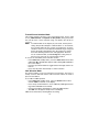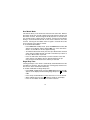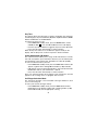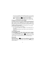
1
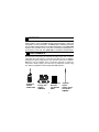
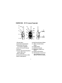
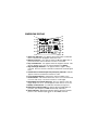
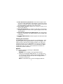
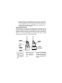
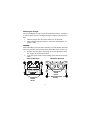
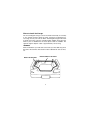
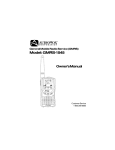
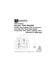
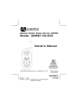
Gener
al Mobile Radio Ser
vice (GMRS)
General
Service
Model: GMRS2VMK
Owner
’s
Owner’s
Man
ual
Manual
EMG
EMG
HI ID
LO
CTC
CTC ID
FAST INTELLIGENT CHARGER
OUT OF
OUT OF
RANGE
RANGE
MODE
SCAN
EMG
Customer Service
1-800-290-6650
CAUTIONS
Never attempt to charge alkaline or dry cell batteries, as batteries may burst causing
personal injury and damage to the product. When recharging nickel metal hydride
(NiMH) batteries with the Audiovox charger, use only Audiovox approved rechargeable batteries. The Audiovox rechargeable batteries were designed to provide
optimum operation for your radio in various environmental conditions. Use of the
Audiovox charger with other brands of batteries is not recommended, as battery
charging times will vary with different brands. Refer to the manufacturer’s instructions for charging other brands of batteries. Avoid placing the GMRS2VMK radio
transceiver for prolonged periods of time in direct sunlight or temperatures below 4° F (-20° C) or above 140 ° F (60° C).
Keep the antenna at 1 inch (2.5 cm) away from your head and body. Do not use
your GMRS2VMK radio transceiver with a damaged antenna.
Place the rubber cover on jacks when not in use.
Check the laws and regulations on the use of radio products in the area
where you drive. Always obey them.
When using the radio product while driving, please:
• Give full attention to driving and to the road.
• Pull off the road and park before transmitting or receiving a call if
driving conditions so require.
GMRS license:
Use of this radio within the United States requires an FCC GMRS license. An
individual 18 years of age or older, who is not a representative of a foreign
government, is eligible to apply for a GMRS system license. You will need two
forms from the FCC; FCC Form 159 and FCC Form 605 Main Form and
Schedule F. You can find the forms online at: http://www.fcc.gov/formpage.html,
or call 1-800-418-3676.
2
FEATURES
Your GMRS2VMK Radio is a portable, easy to use, two-way radio that you can carry
almost anywhere. The Fast Intelligent Charger can be mounted in a vehicle and
is designed for a vehicle environment. The GMRS2VMK is skillfully constructed to
give you reliable communications for many different applications. The GMRS2VMK
is ideal for use around the house, in your boat, on hunting and camping trips, on
the ski slopes or at the mall. The GMRS2VMK is comprised of the items below:
PERFORMANCE
Your transceiver will achieve its maximum operating range when communicating with other transceivers in a flat open area with no trees or buildings
obstructing its signal. Range may be up to five miles under such conditions.
Obstacles such as buildings, trees or mountains will tend to reduce the
transceiver’s effective range. The transceiver is designed to operate using
the Audiovox supplied four AAA rechargeable NiMH batteries.
M O DE
SCAN
CAN
EM G
Radio Part
Number
GMRS-1200
Rechargeable
Batteries
Part Number
HR4U
Fast Intelligent
Charger Part
Number
2VMKCHG
3
Cigarette
Lighter
Adapter Cable
Part Number
2VMKCIG
GMRS2VMK (FCC License Required)
5
6
4
16
8
3
13
12
EMG
EMG
CTC
HI
CTC
14
ID
LO
ID
OUT OF
RANGE
OUT OF
RANGE
2
3
(REF)
MODE
SCAN
EMG
15
1
10
9
7
11
1
(REF)
10. Up Channel/Volume Button
11. Down Channel/Volume
Button
12. MODE Button
13. SCAN/Lock Button
14. Emergency (EMG) Call
Button
15. Power On/Off Control
16. Combination Transmit Indicator (Red)/Receive and
Monitor Indicator (Green)
1. Battery Door
2. Monitor/Backlight Button
3. Detachable Carry Clip
Part Number 2VMKBLT
4. Push-To-Talk (PTT) Button
5. Antenna
6. External Speaker(SPK)/Microphone (MIC) Jacks
7. Built-in Speaker
8. Liquid Crystal Display (LCD)
9. Built-in Microphone
4
GMRS2VMK DISPLAY
8
1
2
EMG
3
HI
CTC
9
LO
ID
4
5
OUT OF
RANGE
6
10
11
12
13
14
15
7
16
1. Beep Tone Indicator: Icon appears when beep button confirmation
tone is selected; icon disappears when tone is off.
2. Monitor Indicator: Icon appears when the Monitor (M) button is
pressed and the channel monitor function is activated.
3. Key Lock Indicator: Icon appears when the keypad is locked. This
function disables keys such as channel up/down and MODE.
4. Signal Strength Indicator: Icon appears when a signal is being
received. The icon consists of five bars to indicate the received signal
level.
5. Coded Tone Controlled Squelch System (CTC) Indicator: Indicator
appears when the CTCSS tone function is active.
6. Large Segment Display: Indicates the channel number in use.
7. Scan Indicator: This function allows the user to scan a channel and/
or a tone code every .5 second to search for a valid signal.
8. RogerBeep Tone On/Off Indicator: This icon appears when the
Roger Beep tone is on, and disappears when tone is not in use.
9. Battery Level Indicator: Icon indicates the battery charge level.
10.Emergency Indicator: EMG Icon appears when the EMG button is
pressed. (The frequency is NOT monitored by authorities).
11. HI/LO Indicators: Appropriate indicator appears when the transmit
power is set to desired output power on the GMRS channels.
5
12.Caller Identification (ID) Indicator: This indication appears when
you select a caller identification code (between 1 and 10). ID selection
operates in conjunction with the small segment display, and can also
be used to identify a calling party in the monitor mode.
13.Small Segment Display: Displays the CTCSS tone option in the
channel from (00-38).
14.Out of Range Indicator: Icon will be on steady when received signal
strength is normal; icon flashes when signal strength becomes weak
and intermittant.
15.Voice Activated Transmission (VOX) Indicator: This function allows
hands free conversation. The indicator appears when the VOX mode
i s activated.
16.Dual Watch Mode Indicator: Indicator appears when dual watch mode
i s active.
Powering the transceiver:
Your GMRS2VMK radio transceiver operates on four AAA batteries. Only
Audiovox approved rechargeable batteries should be recharged in the
radio transceiver using the Fast Intellegent Charger. This will ensure
optimum performance for the GMRS2VMK. Use of the Fast Intellegent
Charger with other brands of batteries is not recommended as battery
charging times will vary. Refer to the manufacturer’s instructions for
charging other brands of batteries.
Batteries
There are three methods of powering the GMRS2VMK:
1. Alkaline Batteries.
WARNING: Do not attempt to recharge Alkaline batteries.
2. Audiovox Rechargeable NiMH Batteries -It is strongly recommended that only Audiovox approved rechargeable batteries and
the Fast Intelligent Charger be used while charging batteries
internal to the transceiver.
NOTE: To extend battery life, avoid overcharging the batteries.
6
3. Various Brands of Rechargeable Batteries - Use of the supplied
Audiovox charger with other brands of rechargeable batteries is
not recommended, as battery charging times will vary with different
brands of batteries. Refer to the manufacturer’s instructions for
charging other brands of batteries.
Installing the batteries:
Battery installation is made more convenient when the carry clip is removed.
To do this, release the spring latch securing the clip to radio and slide the
clip downward and away from the radio body. Next, press down with the
thumb at the embossed arrow, slide the battery cover down and lift off the
battery cover. Insert four AAA batteries (alternate positive ends (+) toward
the bottom of the transceiver, (starting left-to-right).
SPRING
LATCH
COVER
ARROW
CARRY
CLIP
PART
NUMBER
2VMKBLT
+
POSITIVE
TERMINALS
+
BATTERY
COVER
1. Using thumb,
press down on
battery cover at
arrow and slide
cover down to
open.
+
2. Slide the cover
down and then lift
cover at bottom to
open.Remove
cover.
7
+
3. Insert four AAA batteries
(positive (+) end toward
the bottom begining at
left side and alternating
positive terminals as
shown).
Mounting the Charger
The Fast Intelligent Charger can be mounted horizontally or vertically in
a vehicle. Mount the Fast Intelligent Charger using the following procedure:
1. Hold the charger up to the surface where is to be mounted.
2. Using a marker, mark the location of where the mounting holes are
going to made.
WARNING!
Never install above your fuel tank as the holes you must drill may pierce the
tank or the fuel lines. Also check for other obstructions such as wires, etc.
3.
4.
Drill the mounting holes and using the screws provided, mount
the charger in the desired location.
Cover the screw heads of the mounting screws with the covers provided.
VERTICAL MOUNTING
HORIZONTAL MOUNTING
MOUNTING
SCREW
HOLES
MOUNTING SCREW
COVERS
MOUNTING
SCREW
HOLES
8
Where to Install the Charger
The Fast Intelligent Charger can be mounted horizontally or vertically
in any suitable location within the trunk, passenger compartment or
rear cargo area of your vehicle. When mounting the charger in the trunk
it maybe necessary route the cigarette lighter adapter wiring from the
trunk to your car dashboard if no closer power outlet is available. The
cigarette lighter adapter cable is approximately 16 feet long.
WARNING!
Never install above your fuel tank as the holes you must drill may pierce
the tank or the fuel lines. Also check for other obstructions such as wires,
etc.
MOUNT ON SIDE WALL
MOUNT UNDER LIP OF TRUNK
9
Using the Fast Intelligent Charger
The Fast Intelligent Charger will typically fully charge the transceivers
in two hours. LEDs mounted on the front of the charger provide visual
status of the charging process.
Charging Indicators
Status
Steady Yellow:
The charging process is not taking place.
Charging will not occur at temperatures below
14 degrees Fahrenheit (-10 degrees Celsius)
or above 140 degrees Fahrenheit (60 degrees
Celsius).
Blinking Red:
The charging process is not taking place. The
batteries need to be replaced.
Steady Red:
Charging in progress.
NOTE: Observe the charging LED indicators after one
minute to ensure that charging is taking place.
If charging LEDs are blinking, replace the
batteries.
Steady Green:
Batteries are fully charged.
CHARGING LED INDICATORS
10
Powering the Charger with the Cigarette Lighter Adapter
The GMRS2VMK Fast Intelligent Charger obtains its operating power using the Cigarette Lighter Adapter. Use the following procedure to connect
the charger to input power:
1. Insert the GMRS2VMK Cigarette Lighter Adapter connector into
the charger base by aligning it with the pins on the connector on
the back of the charger base.
2. Press down on the connector locking tab and press the connector into place. The connector will lock in place.
3. Connect the GMRS2VMK Cigarette Lighter Adapter connector to a
standard +12 Volt DC power outlet.
4. To release the connector, lift the locking tab and remove the
connector form the charger base.
NOTE
The GMRS2VMK Cigarette Lighter Adapter is equipped with a 2-Amp
fuse mounted beneath the removable cover assembly.
Fast Intelligent
Charger Rear View
Power LED
Indicator
Connect
to a +12VDC
Source
Fuse
Cover
Cigarette Lighter
Adapter Cable
Charger Base 2-Pin Locking
Tab
11
Mounting the Transceiver in the Charger
The transceiver is designed to lock into the Fast Intelligent Charger. Use
the following procedure:
1. While holding the transceiver in the palm of your hand, reach the
carry clip handle and press down to open the carry clip.
2. While the carry clip is in the open position, move the transceiver
downward into the charger base.
3. Press the transceiver firmly into the base.
4. Release the carry clip handle and ensure that the transceiver is
secure by lightly pulling up on the unit. The unit should be locked to
the charger base and the charging indicator should be red.
Carry Clip Spring Latch
Carry Clip Handle
Carry Clip
Part Number
2VMKBLT
Carry Clip
Locking Tab
GMRS2VMKCHG Fast
Intelligent Charger
Side View
12
GMRS2VMK OPERATIONAL MODES
MODE
CHANNEL
SELECT
CTCSS
SELECT
POWER
SELECT
(GMRS Channels Only)
VOX
SELECT
DUAL
WATCH
ROGER
BEEP
BUTTON
BEEP
ID
SELECT
Controls:
CALL
SELECT
Power On/Off (15) Button
Press and hold the power on/off button (
) for at least 2 seconds. You
will hear a confirming melody to indicate the unit is on. To turn the unit
off, press and hold the button for at least 2 seconds.
Adjusting the Volume
With the unit powered on, press the Up Channel/Volume button (
) to
increase volume and the Down Channel/Volume button (
) to decrease
volume. The display will indicate the current volume level between 1 and 7
by the small number in the icon ( U 05 ).
13
Monitor/Display Backlight Button (2)
This button is used to check activity on the current frequency before
transmitting. Check activity by pressing the Monitor (M) Button longer
than 2 seconds; the
icon will apppear on the display and you will
hear static if frequency is clear. Do not transmit if you hear conversation.
Hold down the Monitor Button again longer than 2 seconds and the
icon will disapppear from the display.
The monitor function will temporarily bypass the squelch setting and play
all signals on a given channel. This feature is useful when communicating
with other parties at extreme range.
By pressing the monitor button momentarily, the LCD backlight is turned
on accompanied by a beep tone; the LCD backlight will turn off automatically
in about 5 seconds, or when the monitor button is pressed momentarily
once again.
Push To Talk (PTT) Button (4)
Pressing and holding this button will allow you to speak to any transceiver
that is set to the same channel and privacy code setting as yours. Hold the
transceiver approximately 1 to 2 inches from your face as you speak into
the built in microphone (9). After you have finished speaking, release the
PTT Button to allow reception of incoming signals. It is not possible to
transmit and receive at the same time. The Transmit/Monitor LED (16) at
the upper inside right corner of the LCD Panel (8) will light red while the
PTT Button is pressed.
Releasing the button allows the unit to revert to standby mode. When
receiving an incoming signal, the Transmit/Monitor LED indicator will light
green and the received signal strength indicator (
) will display
the relative strength of the signal.
The PTT Button can also be used as a two-way call ringer. Pressing the
button twice quickly will call another party on the same channel. The Transmit
LED will light red for approximately 3 seconds and then go out.
14
Up Channel/Volume Button (10)
In the standby mode, pressing this button will increment the listening
volume. When in function edit mode this button will be used to adjust the
unit’s settings.
Down Channel/Volume Button (11)
In the standby mode, pressing this button will decrement the listening
volume. When in function edit mode this button will be used to adjust the
unit’s settings.
Mode Button (12)
This button is used to select the various GMRS feature settings such as
channel/CTCSS code selection, VOX mode, etc.
Emergency (EMG) Call Button Button (14)
This radio has a quick access button (EMG) to the Emergency and
Assistance Channel. This channel is not monitored by local authorities.
When using this channel, EMG appears on the display. Pressing this
button will set the transceiver to channel 20, operating on 462.6750 MHz.
External Speaker (SPK)/Microphone (MIC)/(CHG) Jack (6)
This jack accepts an Audiovox headset/microphone connector, or the
Charging Adapter connector. The Charging Adapter is supplied with the
unit. For additional optional equipment and accessories for the GMRS2VMK
visit the Audiovox web site at www.audiovox.com.
Scan/Lock Button (13)
Press this Button momentarily to enable or disable the scan mode. Press
and hold Button for more than 1 second to lock or unlock the key pad,
except Power, PTT and Monitor (M) and Volume Up/Down. When the keypad
is locked, the (
) icon will display in the top left corner.
15
Operating Modes and Features
GMRS Operation:
- From GMRS standby mode, press and hold the (
) button for 2
seconds to turn on power.
- Press the MODE button so the Channel number flashes.
- Select the desired channel with the Up (10) and Down (11) Buttons.
When receiving a call, the signal strength meter appears to indicate
incoming received signal strength and the Monitor section of the
Transmit/Monitor LED (16) lights green.
- Press and hold the PTT button (4) to transmit, then speak into the
microphone clearly and slowly. The Transmit section of the Transmit/Monitor LED (16) lights red.
- Release PTT Button (4) to receive.
- Communication can only be accomplished when the channel and
CTCSS tone frequency of at least two parties are the same.
- The CTC icon will be displayed on the LCD panel if the CTCSS tone
frequency function is enabled.
Channel Selection
In order to communicate with other GMRS units, both transmitting and
receiving party must be on the same frequency.
The GMRS2VMK has 22 channels (frequencies) indicated by the large
digits on the LCD display panel. Channels 1 through 7 are the shared
GMRS/FRS channels. Channels 8-14 are FRS only channels, while
channels 15-22 are assigned GMRS only channels. If an FRS only
channel (8-14) has been selected, the HI or LO indicator will not be
displayed on the LCD panel; otherwise, for channels 1-7 (GMRS/FRS)
and 15-22 (GMRS only), the HI or LO indicator will be displayed. Communication with Audiovox FRS and compatible units is possible on these
seven channels. Before transmitting on the selected channel, press the
Monitor (M) Button (2) to check the activity on that channel. If there is activity
on the selected channel, change to another channel that is clear.
16
To change the channel:
- From GMRS/FRS standby mode, press the MODE button (12) once, or
until the channel number flashes.
- Press the Up Button (10) briefly to move to the next higher main channel number.
- Press the Down Button (11) briefly to move to the next lower main
channel number.
- Press the PTT button momentarily to confirm selection.
CTCSS Mode (Sub-Channel) Selection
The Coded Tone Controlled Squelch System (CTCSS) provides 38 Sub-Frequencies. This feature allows you to utilize the coded squelch tones (01–38)
within a main channel. This enables you to communicate with another party on
the same main channel using the same subcode. (This filters out unwanted
transmissions without the same coded squelch tone). There are 38 CTCSS
Sub-channels for each main channel. A different subcode may be selected for
each of the 22 channels.
To change the CTCSS Sub-channel:
- From GMRS/FRS standby mode, press the MODE Button twice; a
flashing oF or sub-channel number is displayed, together with the
flashing CTC icon. If oF is displayed, press the Up or Down button to
enable the CTCSS mode; the CTC icon will also flash on the display
with the flashing sub-channel number.
- Then press the Up or Down button to select the desired sub-channel
for use (01-38).
- Press the PTT button momentarily to confirm selection.
The CTCSS mode can be turned off by selecting the oF icon as the setting.
NOTE: To communicate with other GMRS/FRS units, they must be
switched to the same channel and CTCSS subcode. To communicate with other GMRS/FRS units that do not have subcodes,
switch your unit to the same channel with the subcode set to oF.
The CTCSS subcodes do not prevent others from hearing your
transmission. This will only allow you to ignore all traffic on a given
channel not using the same subcode.
17
Transmit Power Selection Mode
This feature permits selection of the transmitting power level to high
or low. (FRS channels 1-7 operate on low power.) Using low power,
the unit will have a lower transmit range, but battery life will be increased.
NOTE: You will find that for the majority of your needs, the low-power
setting will provide adequate communications on all channels;
there should seldom be any need to use high power, except in
situations where you need absolute maximum range. Using low
power will greatly extend battery life. We suggest you experiment with switching between low and high power. However,
we do recommend that you not change this setting unless it
proves to be necessary in your particular situation.
To access the transmitter power selection function:
- From GMRS/FRS standby mode, press the MODE Button three times
until the Po HI or Lo indication appears with a flashing HI or LO indication on the display.
- Press the Up or Down button to toggle between the High and Low selections.
- Press the PTT button momentarily to confirm selection.
VOX Selection Mode
This option enables you to have hands-free conversation. Your voice or
nearby sound is detected and the radio transmits without the need to
press the PTT button.
To set radio for VOX operation:
- From GMRS/FRS standby mode, press the MODE button 4 times
until the VOX icon flashes on the display.
- Press the Up or Down button to select VOX On (if oF appears flashing) and the 1-5 VOX level sensitivity.
- Press the PTT button momentarily to confirm the VOX selection.
- The VOX icon will appear steady on the LCD display.
VOX can be turned off by selecting oF as the setting.
18
Dual Watch Mode
This feature allows you to monitor two channels at the same time. While in
dual watch mode, the unit will continuously monitor both the primary and
dual watch channel. Received signals will be played for 5 seconds, then
the unit will resume scanning the two channels. Pressing the PTT button
during a received transmission will set the unit to transmit on the same
channel. Pressing the PTT button when no signal is received will set the
unit to transmit on the primary channel.
To set the Dual Watch Mode:
- From GMRS/FRS standby mode, press the MODE button 5 times; dc
appears on the display with the flashing DW icon. If the dual watch
mode is off, the oF icon will also appear flashing.
- To enable the dual watch mode, press the Up or Down button; the dual
watch channel number will flash and start to increment up or down as
the Up or Down button is pressed.
- Press the PTT button momentarily to confirm selection of the dual
watch channel. The display will now alternate between the primary channel and the dual watch channel just selected.
Roger Beep Tone
The Roger Beep is a tone which is automatically transmitted whenever the
PTT button is released. This tone alerts the receiving party that the transmission has been terminated intentionally.
To enable and disable the Roger Beep tone:
- From GMRS standby mode, press the MODE Button 6 times until rb
appears on the display with the flashing Roger Beep icon ( ) and On
or oF.
- Press the Up or Down Button to select the tone on or off as desired.
- When enabled, the tone icon (
) appears steady on the display.
- Press the PTT button momentarily to confirm selection.
19
Key Tone
This feature allows the transceiver to sound a confirmation tone whenever
the following keys are pressed: Monitor (M) Button, Up/Down Buttons, MODE
Button, SCAN Button, or the EMG Button.
To turn the key tones on or off:
- From GMRS/FRS standby mode, press the MODE Button 7 times
until bP, the Bell (
) icon, and On or oF flash on the LCD display.
- Press the Up or Down Button to toggle the key tone feature On or Off.
- Press the PTT button momentarily to confirm selection.
When the key tone feature is on, the Bell icon appears steady on the
display, and the beep tones sound in response to button activation.
Caller Identification (ID) Select
The caller ID function allows you to assign an ID code between 1 and 10;
this code accompanies your transmission whenever you call another party,
and will appear at the receiving unit, provided it has caller ID capability.
To select a caller ID code for your unit:
- From GMRS/FRS standby mode, press the MODE button 8 times; Id
appears, together with a flashing ID and number (or oF) indication.
- If oF appears, press the Up or Down Button to select the desired caller
identification code for your unit between 1 and 10.
- Press the PTT button momentarily to confirm selection.
Now, your caller ID number will accompany each transmission, and will
appear on the receiving unit, if so equipped, and vice-versa.
Call Ringer Selection Mode
The transceiver provides 3 user-selectable call ringer melodies to alert
you to an incoming call.
To select your favorite call ringer melody:
- From GMRS/FRS standby mode, press the MODE button 9 times;
C will appear on the display, together with a flashing number (or oF)
between 01 and 03, and an appropriate call ring.
20
- Press the Up or Down Button to preview and hear the 3 available call
melodies.
- Press the PTT button momentarily to confirm selection.
Refer to the PTT button (4) to transmit ring signal.
Channel Scan Operation
This feature allows you to monitor all channels automatically for valid
signals. While scanning, you can transmit and receive. When a signal is
received, the scan is interrupted and will return to scan mode 5 seconds
after reception is terminated.
NOTE: While the scan function is active, the MODE button will be
inoperative. The scan mode will reduce the overall battery life
since the battery save function is overridden.
To enable the channel scan mode:
- From GMRS/FRS standby mode, momentarily press the SCAN But
ton; (SCAN) will appear on the LCD display.
- The radio will display each channel (1-22) in order as the scan mode
operates to find an active main channel.
- If the unit doesn’t find any signals and you want to transmit, press the
PTT switch to return to home channel operation. The transceiver will
automatically resume scanning approximately 5 seconds after the
communication is completed.
- If there is no activity and you want to leave the scan mode, press the
SCAN button momentarily and the unit will return to normal operation;
(SCAN) icon will disappear from the LCD display.
Auto Key Lock Selection Mode
This feature prevents accidental channel change to the preferred settings
of the unit. The Auto Key Lock function temporarily disables the MODE and
SCAN Buttons.
To access the Auto Key Lock selection menu:
- From GMRS/FRS standby mode, press and hold the Scan Button for
over 2 seconds to Lock the Auto Key function; the (
) icon appears
on the display.
21
- The Power, PTT, Up/Down, EMG and Monitor Buttons are not effected.
- To unlock the Auto Key function, press and hold the SCAN button for at
least 2 seconds; the icon (
) disappears from the display.
NOTE: If the unit is turned off while Key Lock is on, the Key Lock
mode will still be in effect when the unit is turned on again.
Emergency and Assistance Channel Mode
This radio has a quick access button (EMG) to the Emergency and
Assistance Channel. This channel is not monitored by local authorities.
When using this channel, EMG appears on the display. Pressing this
button will set the transceiver to the channel 20, 462.6750 MHz). The
Emergency Channel can be used transmit and receive on a special
frequency (CH20: 462.6750 MHz).
The Emergency Channel can be selected quickly from any user mode.
To access the Emergency Channel mode:
- Press Emergency (EMG) Button; EMG and Channel 20 appears on
the display.
- To turn off the Emergency Channel feature, press and release the
EMG Button.
Out of Range Indication
The GMRS2VMK provides an Out-of-Range indication when reception is
no longer intelligible or too weak to be discernible. When this condition
icon appears on the display,
occurs, the OUT OF RANGE message and
reminding you that you are outside the 5-mile range of the unit, or that
signal reception is being obstructed by native or man-made objects.
Battery Alert
When the battery icon (
) blinks on the LCD panel, recharge unit or
install fresh batteries. If the batteries are not replaced the (
) icon will
appear and an audio tone will sound to warn the user that the batteries
must be replaced.
22
NOTES FOR GOOD COMMUNICATION
1 . The GMRS2VMK 22 channels are shared on a ‘take turns’ basis.
This means other groups may be talking on any of the channels.
A common code of ethics/courtesy is to switch to another vacant
channel and not to attempt to talk over someone who is already using
the channel you first selected.
2. The GMRS2VMK has been designed to maximize performance
and improve transmission range in the field. To avoid interference,
it is recommended that you do not use the units closer than 5 feet
apart.
3. For best transmission results, always keep your mouth about 2-3
inches from the microphone (9) and speak slowly in a normal voice.
4. To increase battery life, avoid features such as Scan and Dual
Watch. These features will reduce operating time considerably.
Warning
• Do not operate the transceiver unless you are licensed to do so.
• Remove the batteries from the transceiver if it is not expected to be used
for long periods. This will eliminate the possibility of chemicals leaking
from the batteries and corroding the transceiver.
• Avoid exposing the transceiver to water or extremes of temperature.
• Do not use this device in or near a mining facility, which uses remotely
triggered explosives or in areas labeled “Blasting Area”. Premature or
accidental detonation may result.
• Do not attempt to modify or in any way increase the output of this
transceiver. Its output is designed to meet the legal limits set by the FCC.
• Do not use this device or change its batteries in potentially explosive
atmospheres as sparks in such areas could result in an explosion.
• Turn your transceiver off wherever posted notices restrict the use of radios
or cellular telephones. Facilities such as hospitals may use equipment
that is sensitive to RF energy.
23
•Do not place your radio in front of a vehicle’s air-bag. If the air-bag deploys, it could propel the transceiver like a projectile causing bodily injury.
Troubleshooting
Problem
Possible cause
No transmission
while pressing
the PTT Button
Weak batteries
Incorrect battery polarity
Weak or no
signal received
Weak batteries
Channel and privacy
code not set the same
as target transceiver
Volume level too low
PTT Button inadvertently
depressed
Excessive radio interference
on a particular channel
Obstruction of radio signal
Unit beeps, but
will not function
when turned on
Reception of
unwanted signals
Transceiver does
not charge
Batteries extremely
discharged
CTCSS privacy mode
not on
Interference from
electronic devices such
as computers or TVs
Cigarette Ligther Adapter
24
Correction
Charge or replace batteries
Install the batteries
following the directions in
paragraph Installing the
Batteries.
Charge or replace batteries
Adjust the transceiver’s
settings to match those
settings of the target
transceiver.
Increase volume level
Release PTT Button
Change to a different
channel.
Avoid operating in or near
large buildings or vehicles.
Charge or replace batteries
Turn on the CTCSS privacy
mode and set code number to
match the setting of the
target transceiver.
Turn the devices off or move
farther away from them.
Check fuse and replace if
necessary.
Tec
hnical Specif
ica
tions:
echnical
Specifica
ications:
General
Frequency Range:
Channels 1-7 (Shared
with FRS radios)
Channels 8-14 (FRS only)
Channels 15-22 (GMRS only)
Channel Spacing
Privacy Codes
Transceiver Dimensions
(W x H x D) (Without Antenna)
Charger Base Dimensions
(W x H x D)
Power Supply
Transceiver Power Source
Operating Time
(Transmit: Receive: Standby
(5:5:90 Ratio) (Based on
alkaline batteries)
Charger Base
Receiver
Useable Sensitivity
Maximum Audio Output Power
Modulation Distortion
Transmitter
RF Output Power
Maximum Deviation
Modulation Distortion
Refer to frequency chart on next page
Refer to frequency chart on next page
Refer to frequency chart on next page
12.5 kHz
38 for each main channel
2.10 in
x 3.86 in x 1.10 in
53.4 mm x 98 mm x 28 mm
6.4 in
x 4.5 in x 2.4 in
163.5 mm x 113.5 mm x 62 mm
Alkaline Batteries, AAA (4), 6 VDC
Ni-MH rechargeable, AAA (4),
4.8 VDC, 650 mAh
30 Hours Low Power
14 Hours High Power
12VDC, 750mA +/-50mA
>-119 dBm
> 0.3 Watt maximum (8 Ohm )
< 5% (1 kHz 70%)
1.8 Watt maximum (High Power)
0.5 Watt maximum (Low Power)
<+/- 2.5 kHz
< 5% (1 kHz 70%)
25
This transceiver complies with FCC regulations for use in the United
States of America. Use in other countries may be prohibited or restricted
by local regulation. Please check with the local regulating agency before using this device outside the United States of America.
Main Channel Frequencies:
CHANNEL /TYPE
FREQ (MHz )
CHANNEL /TYPE
FREQ (MHz )
1
GMRS/FRS
462.5625
12
FRS
467.6625
2
GMRS/FRS
462.5875
13
FRS
467.6875
3
GMRS/FRS
462.6125
14
FRS
467.7125
4
GMRS/FRS
462.6375
15
GMRS
462.5500
5
GMRS/FRS
462.6625
16
GMRS
462.5750
6
GMRS/FRS
462.6875
17
GMRS
462.6000
7
GMRS/FRS
462.7125
18
GMRS
462.6250
8
FRS
467.5625
19
GMRS
462.6500
9
FRS
467.5875
20
GMRS
462.6750
10 FRS
467.6125
21
GMRS
462.7000
11 FRS
467.6375
22
GMRS
462.7250
NOTE: Channels 1 through 7 are shared with FRS radios.
Channels 8 through 14 are FRS only.
Channels 15 through 22 are GMRS only.
26
Continuous Tone Coded Squelch System Tone
Frequencies (in Hz)
CTCSS
Freq. Hz
CTCSS
1
2
3
4
5
6
7
8
9
10
11
12
13
14
15
16
17
18
19
67.0
71.9
74.4
77.0
79.7
82.5
85.4
88.5
91.5
94.8
97.4
100.0
103.5
107.2
110.9
114.8
118.8
123.0
127.3
20
21
22
23
24
25
26
27
28
29
30
31
32
33
34
35
36
37
38
* oF = No Tone
27
Freq. Hz
131.8
136.5
141.3
146.2
151.4
156.7
162.2
167.9
173.8
179.9
186.2
192.8
203.5
210.7
218.1
225.7
233.6
241.8
250.3
90 DAY LIMITED WARRANTY
Applies to Audiovox Family Radio and General Mobile Service Products.
AUDIOVOX CORPORATION (the Company) warrants to the original retail purchaser of this
product that should this product or any part thereof, under normal use and conditions, be proven
defective in material or workmanship within 90 days from the date of original purchase, such
defect(s) will be repaired or replaced with new or reconditioned product (at the Company's option)
without charge for parts and repair labor.
To obtain repair or replacement within the terms of this Warranty, the product is to be delivered
with proof of warranty coverage (e.g. dated bill of sale), specification of defect(s),
transportation prepaid, to the warranty center at the address shown below.
The Company disclaims liability for communications range of this product.
This Warranty does not apply to any product or part thereof which, in the opinion of the
Company, has suffered or been damaged through alteration, improper installation, mishandling, misuse, neglect, accident, or by removal or defacement of the factory serial number/
bar code label(s). THE EXTENT OF THE COMPANY'S LIABILITY UNDER THIS WARRANTY
IS LIMITED TO THE REPAIR OR REPLACEMENT PROVIDED ABOVE AND, IN NO EVENT,
SHALL THE COMPANY'S LIABILITY EXCEED THE PURCHASE PRICE PAID BY
PURCHASER FOR THE PRODUCT.
This Warranty is in lieu of all other express warranties or liabilities. ANY IMPLIED
WARRANTIES, INCLUDING ANY IMPLIED WARRANTY OF MERCHANTABILITY, SHALL BE
LIMITED TO THE DURATION OF THIS WRITTEN WARRANTY. ANY ACTION FOR BREACH
OF ANY WARRANTY HEREUNDER INCLUDING ANY IMPLIED WARRANTY OF MERCHANTABILITY MUST BE BROUGHT WITHIN A PERIOD OF 30 MONTHS FROM DATE OF
ORIGINAL PURCHASE. IN NO CASE SHALL THE COMPANY BE LIABLE FOR ANY
CONSEQUENTIAL OR INCIDENTAL DAMAGES FOR BREACH OF THIS OR ANY OTHER
WARRANTY, EXPRESS OR IMPLIED, WHATSOEVER. No person or representative is
authorized to assume for the Company any liability other than expressed herein in connection with
the sale of this product.
Some states do not allow limitations on how long an implied warranty lasts or the exclusion
or limitation of incidental or consequential damage so the above limitations or exclusions may
not apply to you. This Warranty gives you specific legal rights and you may also have other
rights which vary from state to state.
AUDIOVOX CORPORATION, 150 MARCUS BLVD., HAUPPAUGE, NEW YORK 11788
1-800-290-6650
128-5385A
© 2003 Audiovox Electronics Corp., Hauppauge, NY 11788
28
Printed in China
128-6616