1
July 15, 2012
Lit. No. B64092, Rev. 06
Models 760TR, 810TR, 8100TR,
860TR, 8600TR & 8611TR
Installation Instructions & Owner's Manual
CAUTION
See your BLIZZARD sales outlet/Web site for
specific vehicle application recommendations
before installation.
CAUTION
Read this document before installing the
snowplow.
CAUTION
Read this document before operating or
servicing snowplow.
This manual supersedes all editions with an earlier date.
TABLE OF CONTENTS
PREFACE.................................................................... 4
REMOVING FROM STORAGE & LIFTING ............. 27
SAFETY INFORMATION ............................................ 5
OPERATION ............................................................... 8
TECHNICAL SPECIFICATIONS &
CENTER OF GRAVITY INFORMATION ............... 28
810TR, 8100TR & 8611TR .................................... 8
810TR, 8100TR & 8611TR .................................. 28
760TR, 860TR & 8600TR ..................................... 9
760TR, 860TR & 8600TR ................................... 29
UNPACKING & INSPECTION .................................. 10
TROUBLESHOOTING .............................................. 30
TORQUE SPECIFICATIONS .................................... 11
PARTS LISTS ........................................................... 31
MOLDBOARD & A-FRAME ASSEMBLY ................ 13
Moldboard & Wing Parts – 810TR & 8611TR ..... 31
810TR, 8100TR & 8611TR .................................. 14
Moldboard & Wing Parts – 8100TR .................... 34
760TR, 860TR & 8600TR ................................... 16
Moldboard & Wing Parts – 760TR & 860TR....... 36
ELECTRICAL & HYDRAULIC SYSTEMS ............... 19
Blade Assembly – 8600TR ................................. 38
General System Schematics – 810TR,
8100TR & 8611TR ........................................... 19
Blade Components – 8600TR ........................... 40
Hydraulic Guide – 810TR, 8100TR & 8611TR .... 20
A-Frame & Pivot Beam Parts – 810TR &
8100TR ............................................................ 42
OSCILLATING PLATE ASSEMBLY......................... 21
A-Frame & Pivot Beam Parts – 8611TR ............. 44
ELECTRICAL INSTALLATION – 810TR,
8100TR & 8611TR MODELS ................................. 22
A-Frame & Pivot Beam – 760TR, 860TR
& 8600TR ........................................................ 46
MOUNTING & DISMOUNTING INSTRUCTIONS .... 23
Manifold Parts – 810TR, 8100TR & 8611TR ....... 48
TESTING YOUR SNOWPLOW................................. 24
Manifold Parts – 760TR, 860TR & 8600TR........ 49
ADJUSTABLE SHOE ASSEMBLY .......................... 25
Accessories & Kits – All Models ......................... 50
MAINTENANCE ........................................................ 26
Lit. No. B64092, Rev. 06
3
July 15, 2012
PREFACE
PREFACE
AUTHENTIC PARTS AND ACCESSORIES
Congratulations on purchasing the most advanced
snowplow available! The POWER PLOW™ snowplow
is clearing new trails for innovative design, rugged
durability, quality craftsmanship and superior
performance. SPEEDWING™ blades create a
whole new category for multi-position truck-mounted
snowplows. Our innovative products are tested all
across the snowbelt.
Your BLIZZARD snowplow is a valuable investment.
The best way to assure original equipment reliability
and efficiency is to purchase only Authentic Parts
and Accessories. "Will-fit" parts and accessories can
alter your snowplow's performance characteristics and
may affect your product warranty.
Protect your investment by staying with the best—
original BLIZZARD parts and accessories from your
local BLIZZARD outlet.
This manual provides safety, operation and
maintenance information for your new BLIZZARD®
snowplow. To keep your snowplow in good condition,
read and understand this manual and follow its
recommendations. Failure to do so may affect your
warranty coverage.
When service is necessary, your local BLIZZARD
distributor knows your snowplow best. Contact your
BLIZZARD outlet for maintenance, service or any
other assistance you require.
If you have not already done so, please visit
www.blizzardplows.com to register your new
SPEEDWING or POWER PLOW snowplow!
Lit. No. B64092, Rev. 06
4
July 15, 2012
SAFETY
SAFETY DEFINITIONS
WARNING/CAUTION & INSTRUCTION
LABELS
WARNING
Become familiar with and inform users about the
warning and instruction labels on the back of the
blade.
Indicates a potentially hazardous situation
that, if not avoided, could result in death or
serious personal injury.
NOTE: If labels are missing or cannot be read, see
your sales outlet.
CAUTION
Indicates a potentially hazardous situation
that, if not avoided, may result in minor or
moderate injury. It may also be used to alert
against unsafe practices.
NOTE: Indicates a situation or action that can lead
to damage to your snowplow and vehicle or other
property. Other useful information can also be
described.
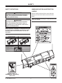
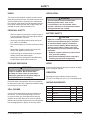
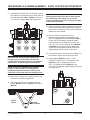
MOUNT INSTRUCTIONS
DISMOUNT INSTRUCTIONS
Read Owner's Manual for Complete Instructions.
Read Owner's Manual for Complete Instructions.
Hook
Hook
Oscillating
Plate
Oscillating
Plate
Lever
Receiving
Hole
Lever
Receiving
Hole
WARNING: Keep fingers away from snowplow and tractor mounting points. Follow tractor labeling and owner's manual.
• Position the tractor close to the snowplow and align the mount points on the tractor
with the hooks on the back oscillating plate of the snowplow.
• Slowly raise the tractor mounting points until the tractor engages the snowplow
hooks. Turn the engine OFF.
• Engage both locking levers on the tractor by rotating
each handle 90° into a horizontal position. The tractor
locking levers shall insert into the snowplow
lever receiving holes.
• Attach all hydraulic hoses on the snowplow to the
auxiliary hydraulic connections located on the tractor.
On some tractor models, it may be necessary to initiate
an auxiliary hydraulic switch on the tractor prior to
operating the snowplow.
• Connect the snowplow wire harness to either the pistol
grip control or auxiliary electrical connection on the
tractor.
• Lower the snowplow on a flat, level surface and turn the engine OFF.
• Disconnect the snowplow wire harness from the tractor.
• Disconnect all hydraulic hoses on the snowplow from the auxiliary hydraulic
connections located on the tractor.
• Disengage both locking levers on the tractor by rotating
each handle 90° into a vertical position. The tractor
locking levers shall withdraw from the snowplow lever
receiving holes.
• Turn the engine ON. Slowly lower the tractor mounting
points until the tractor clears the snowplow hooks.
• Back the tractor away slowly.
44832
U.S. Patents 5,638,618; 5,899,007; 6,178,669; 6,276,076; 6,393,737; 6,408,549; 6,412,199; 6,442,877; 6,615,513; CAN Patents 2,184,922; 2,229,783; 2,259,508; 2,358,145; 2,358,354; 2,466,195; and other patents pending.
POWER PLOW™ &
SPEEDWING™ Blades Only
(both sides)
Lit. No. B64092, Rev. 06
5
July 15, 2012
SAFETY
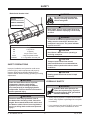
Blade Serial Number Label
WARNING
Do not exceed vehicle operative
capacity including the blade. See
vehicle rating label.
Blizzard
PO BOX 245038
Milwaukee, WI 53223
NNNNNNNNNNNNNNNNNNNNNNNNNNNN
YYMMDDLLXXXXZZZZZ
YYMMDDLLXXXXZZZZ
WARNING
Never stand, work or reach under lift arms or
lift cylinders without employing a lift arm stop
or stand.
WARNING
Code
Definition
YY
MM
DD
LL
XXXX
ZZZZZZ
2-digit Year
2-digit Month
2-digit Day
2-digit Location Code
4-digit Sequential Number
5- to 7-digit Blade Assembly PN
To prevent accidental movement of the blade,
always turn the control OFF whenever the
snowplow is not in use. The power indicator
light will turn OFF.
CAUTION
Read Owner's Manual before operating or
servicing snowplow.
CAUTION
Transport speed should not exceed
vehicle manufacturer's recommendations.
Further reduce speed under adverse travel
conditions.
SAFETY PRECAUTIONS
Improper installation and operation could cause
personal injury, and/or equipment and property
damage. Read and understand labels and the
Owner's Manual before installing, operating or making
adjustments.
CAUTION
Plowing speed should not exceed 10 mph
(16 km/h).
WARNING
HYDRAULIC SAFETY
Lower the blade when vehicle is parked.
Temperature changes could change
hydraulic pressure, causing the blade to
drop unexpectedly or damaging hydraulic
components. Failure to do this could result in
serious personal injury.
WARNING
Hydraulic fluid under pressure can
cause skin injection injury. If you are
injured by hydraulic fluid, get medical
attention immediately.
WARNING
• Always inspect hydraulic components and hoses
before using. Replace any damaged or worn parts
immediately.
The driver shall keep bystanders clear of
the blade when it is being raised, lowered or
angled. Do not stand between the vehicle and
the blade or within 8 feet of a moving blade. A
moving or falling blade could cause personal
injury.
Lit. No. B64092, Rev. 06
• If you suspect a hose leak, DO NOT use your hand
to locate it. Use a piece of cardboard or wood.
6
July 15, 2012
SAFETY
VENTILATION
FUSES
The electrical and hydraulic systems contain several
blade-style automotive fuses. If a problem should occur
and fuse replacement is necessary, the replacement
fuse must be of the same type and amperage rating as
the original. Installing a fuse with a higher rating can
damage the system and could start a fire.
WARNING
Vehicle exhaust contains lethal fumes.
Breathing these fumes, even in low
concentrations, can cause death. Never
operate a vehicle in an enclosed area without
venting exhaust to the outside.
PERSONAL SAFETY
BATTERY SAFETY
• Remove ignition key and put the vehicle in park or
in gear to prevent others from starting the vehicle
during installation or service.
CAUTION
Batteries normally produce explosive gases,
which can cause personal injury. Therefore,
do not allow flames, sparks or lit tobacco
to come near the battery. When charging or
working near a battery, always cover your
face and protect your eyes, and also provide
ventilation.
• Batteries contain sulfuric acid, which burns
skin, eyes and clothing.
• Disconnect the battery before removing or
replacing any electrical components.
• Wear only snug-fitting clothing while working on
your vehicle or snowplow.
• Do not wear jewelry or a necktie, and secure long
hair.
• Wear safety goggles to protect your eyes from
battery acid, gasoline, dirt and dust.
• Avoid touching hot surfaces such as the engine,
radiator, hoses and exhaust pipes.
• Always have a fire extinguisher rated BC handy,
for flammable liquids and electrical fires.
NOISE
FIRE AND EXPLOSION
Airborne noise emission during use is below 70 dB(A)
for the snowplow operator.
WARNING
Gasoline is highly flammable and gasoline
vapor is explosive. Never smoke while
working on vehicle. Keep all open flames
away from gasoline tank and lines. Wipe up
any spilled gasoline immediately.
VIBRATION
Operating snowplow vibration does not exceed
2.5 m/s2 to the hand-arm or 0.5 m/s2 to the whole body.
Be careful when using gasoline. Do not use gasoline
to clean parts. Store only in approved containers away
from sources of heat or flame.
SNOWPLOW WEIGHTS
Wt (lb)
Wt (kg)
CELL PHONES
7'-6"
760TR
895
406
8'
8100TR
1132
513
A driver's first responsibility is the safe operation of
the vehicle. The most important thing you can do
to prevent a crash is to avoid distractions and pay
attention to the road. Wait until it is safe to operate
Mobile Communication equipment such as cell phones,
text messaging devices, pagers or two-way radios.
8'-6"
8611TR
1728
784
8'
810TR
1132
513
8'-6"
860TR
944
428
8'-6"
8600TR
885
401
Lit. No. B64092, Rev. 06
Size
7
Blade Assembly
July 15, 2012
OPERATION – 810TR, 8100TR & 8611TR MODELS
Your POWER PLOW™ snowplow is the most
advanced and versatile snowplow on the market.
The snowplow blade and wings can be adjusted into
an infinite number of plowing positions. Review the
illustrations below to determine the best position for
your plowing needs.
WARNING
Never use the snowplow attachment to carry
people, as a man lift or as a work platform.
WARNING
When plowing with down pressure, do not
cause the front wheels on the tractor to raise
above ground.
A.
A. Compact Position
(8' or 8'-6" Blade Width)
• Primary position when transporting the
snowplow
• For use in heavy snow conditions with poor
visibility, initial clearing and tight quarters
• Ideal application: residential driveways, small
roads
B.
B. WIDE PASS™ Position
(10' or 11'-3" Blade Width)
• Primary position for clearing large surfaces
• For use in light snow conditions with good
visibility, final clearing and clean-up
• Ideal application: large parking lots, widening
roadways
C. BUCKET BLADE™ Position
(9'-3" or 9'-10" Blade Width)
• Primary position for transporting snow
• For use in initial clearing with decent visibility,
transporting large volumes of snow, final
clean-up
• Ideal application: roadway intersections
C.
D. WIDE PASS Position Angled with Wing
Forward
• Primary position for accelerated angled plowing
• For use in directional plowing, cornering,
diverting snow away from objects or buildings
• Ideal application: plowing adjacent to buildings,
driveway/road intersections
E. Oscillating Feature
• Primarily used for uneven surfaces
• Adjusts to numerous tractor makes and models
• Ideal application: commercial and residential
applications
D.
Lit. No. B64092, Rev. 06
8
July 15, 2012
OPERATION – 760TR, 860TR & 8600TR MODELS
Your SPEEDWING™ snowplow is the newest
multi-position snowplow on the market. The snowplow
blade can be adjusted into a variety of plowing
positions. Review the illustrations below for instruction
on maneuvering your snowplow.
WARNING
Never use the snowplow attachment to carry
people, as a man lift or as a work platform.
WARNING
A.
When plowing with down pressure, do not
cause the front wheels on the tractor to raise
above ground.
A. BUCKET BLADE™ Position
(7'-7" or 8'-7" Blade Width)
Automatic position when blade is not angled;
creates a scoop and eliminates trails.
• Primary position for transporting snow
• For use in initial clearing with decent visibility,
transporting large volumes of snow, final clean-up
• Ideal application: residential driveways, small
roads, roadway intersections
B.
B. Angled Width w/Trailing Wing
(6'-7" or 7'-10" Blade Width)
An angled blade will automatically extend the
trailing wing. The snowplow has reached its
maximum angled position when the blade stops
moving to the side.
• Primary position for accelerated angled plowing
• For use in directional plowing, cornering,
diverting snow away from objects or buildings
• Ideal application: plowing adjacent to buildings,
driveway/road intersections
C.
C. Back Blade Position
(8'-7" or 9'-9" Blade Width)
Lock the wings into place to create the largest
clearing path and get the most out of your wings.
• Primary position for clearing large surfaces
• For use in light snow conditions with good
visibility, final clearing and clean-up
• Ideal application: large parking lots, widening
roadways
Lit. No. B64092, Rev. 06
9
July 15, 2012
UNPACKING & INSPECTION
Your snowplow has been packaged to withstand
transit and weather related damage. Fully inspect
all components upon receipt of your snowplow.
In the event of shipping damage or missing
parts, immediately contact our Customer Support
Department at 1-888-680-8600.
Once you have inspected all parts and removed all
packaging materials, your snowplow is ready to be
fully assembled.
Retain this information for your records.
Date of Purchase: ___________________________
Begin unpacking and inspection in the following order:
Dealer/Distributor: __________________________
1.
Remove the shipping document from the end
panel of the pallet wrap. Retain all documentation
for your records.
Dealer Phone Number: _______________________
Snowplow Serial Number: ____________________
2. All wood framing and polyethylene material should
be removed from the pallet for easy access to the
snowplow.
3. Due to the odd shaped components and size
of several assembly parts, various cable ties
and corrugated material are used for scratch
resistance and package orientation. Please
remove these items prior to assembly.
4. Place the main blade assembly on a flat, level
surface.
Lit. No. B64092, Rev. 06
10
July 15, 2012
TORQUE SPECIFICATIONS
TORQUE CHART
CAUTION
Read instructions before assembling.
Fasteners should be finger tight until
instructed to tighten according to the torque
chart. Use standard methods and practices
when attaching snowplow including proper
personal protective safety equipment.
Grade Identification for J429–Grade 5 Bolt
Grade Identification for J429–Grade 8 Bolt
SAE J429 Grade 5 Torque Values
Tightening Torque
Nominal
Clamp Loads
Thread Size
(lb)
"Lubricated"
"Dry"
1/4-20
2,000
6 ft-lb
8 ft-lb
5/16-18
3,350
13 ft-lb
18 ft-lb
3/8-16
4,950
23 ft-lb
31 ft-lb
7/16-14
6,800
37 ft-lb
50 ft-lb
1/2-13
9,050
57 ft-lb
75 ft-lb
9/16-12
11,600
82 ft-lb
109 ft-lb
5/8-11
14,500
113 ft-lb
151 ft-lb
3/4-10
21,300
200 ft-lb
266 ft-lb
7/8-9
29,435
321 ft-lb
430 ft-lb
1-8
38,600
482 ft-lb
640 ft-lb
SAE J429 Grade 8 Torque Values
Tightening Torque
Nominal
Clamp Loads
Thread Size
(lb)
"Lubricated"
"Dry"
1/4-20
2,850
9 ft-lb
12 ft-lb
5/16-18
4,700
18 ft-lb
25 ft-lb
3/8-16
6,950
32 ft-lb
44 ft-lb
7/16-14
9,600
53 ft-lb
70 ft-lb
1/2-13
12,800
80 ft-lb
107 ft-lb
9/16-12
16,400
115 ft-lb
154 ft-lb
5/8-11
20,300
159 ft-lb
211 ft-lb
3/4-10
30,100
282 ft-lb
376 ft-lb
7/8-9
41,550
454 ft-lb
606 ft-lb
1-8
54,540
680 ft-lb
900 ft-lb
8.8
Grade Identification for Metric–Grade 8.8 Bolt
Diameter
(mm)
5
6
7
8
10
12
14
16
18
20
10.9
Metric Class 8.8 Torque Values
Tightening Torque
Clamp Loads
(lb)
"Lubricated"
"Dry"
1,389
3 ft-lb
5 ft-lb
1,965
6 ft-lb
8 ft-lb
2,826
10 ft-lb
13 ft-lb
3,579
14 ft-lb
19 ft-lb
5,672
28 ft-lb
37 ft-lb
8,243
49 ft-lb
65 ft-lb
11,246
77 ft-lb
103 ft-lb
15,882
125 ft-lb
167 ft-lb
19,423
172 ft-lb
229 ft-lb
24,784
244 ft-lb
325 ft-lb
Lit. No. B64092, Rev. 06
Grade Identification for Metric–Grade 10.9 Bolt
Diameter
(mm)
5
6
7
8
10
12
14
16
18
20
11
Metric Class 10.9 Torque Values
Tightening Torque
Clamp Loads
(lb)
"Lubricated"
"Dry"
1,987
5 ft-lb
7 ft-lb
2,812
8 ft-lb
11 ft-lb
4,044
14 ft-lb
19 ft-lb
5,121
20 ft-lb
27 ft-lb
8,116
40 ft-lb
53 ft-lb
11,796
70 ft-lb
92 ft-lb
16,092
111 ft-lb
148 ft-lb
21,970
173 ft-lb
231 ft-lb
26,868
238 ft-lb
317 ft-lb
34,284
338 ft-lb
450 ft-lb
July 15, 2012
TORQUE SPECIFICATIONS
37° JIC Flare Torque Values
Turns
Size
ft-lb
Assembly Steps
min–max
N/A
N/A
2
2
1-1/2
1-1/2
1-1/2
1-1/4
1
1
1
1
1
-02
-03
-04
-05
-06
-08
-10
-12
-14
-16
-20
-24
-32
6–7
8–9
11–12
14–15
18–20
36–39
57–63
79–88
94–103
108–113
127–133
158–167
245–258
1. Make sure the tubing and threads are clean.
2. Lubricate the threads with 10W hydraulic fluid.
3. Hand tighten the nut/sleeve to approximately 30 in-lb.
4. Make alignment marks on the nut and fitting.
5. Tighten to turn or torque specification.
6. When fully tightened, make a second set of alignment marks at the fully tightened position.
NOTE: Torque values specified are for threads lubricated with 10W hydraulic fluid.
Overtightening will reduce the clamping force resulting in loss of seal and reduction of flow.
O-Ring Boss Torque Values
Size
ft-lb
Assembly Steps
min–max
-02
-03
-04
-05
-06
-08
-10
-12
-14
-16
-20
-24
-32
6–7
8–10
13–15
17–21
22–25
40–43
43–57
68–75
90–99
112–123
146–200
154–215
218–290
1. Verify the port, O-ring, sealing surfaces and threads are clean and free of damage.
2. Lubricate the threads and the O-ring with 10W hydraulic fluid.
3. For an adjustable ORB, completely back off the locknut and washer.
4. Hand tighten the fitting until it contacts the port spotface. Point the elbow or tee in the desired
direction and hold.
5. Torque to specification.
NOTE: Torque values specified are for threads lubricated with 10W hydraulic fluid.
Lit. No. B64092, Rev. 06
12
July 15, 2012
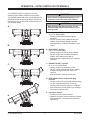
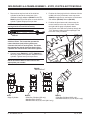
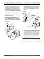
MOLDBOARD & A-FRAME ASSEMBLY – 810TR, 8100TR & 8611TR MODELS
1.
Remove dust cap from both of the slide box
cylinders located at the center/rear of the
moldboard. Attach adapters (B60007 for 810TR;
56695 for 8611TR) to both ports on each slide box
cylinder. Tighten fittings per torque chart.
3. Position the front (top) hole in the A-frame with the
middle hole in the pivot beam. Insert cap screw
(50605) through the top, and secure on the bottom
with washer (B61203) and nut (B61008).
4. Position the pivot beam and A-frame near the
mount locations at the rear of the blade. Place
the right and left group of hydraulic hoses
(connected to the slide box cylinders) through the
1-1/2" diameter rubber grommet openings in the
front face of the pivot beam.
NOTE: All of the hydraulic adapters can be found
packaged with the manifold assembly.
Extend
Retract
NOTE: The positions for the rod- and base-end
slide box hoses. The hoses that operate the
retract functions (rod) of the cylinders are
closest to the base of each cylinder. The hoses
that operate the extend functions (base) of the
cylinders are closest to the rod of each cylinder.
2. Connect hoses (B60223 for 810TR; B60224 for
8611TR) to each of the hydraulic adapters on the
cylinders. Tighten hoses per torque chart.
NOTE: Review the label on each hose for the
appropriate part number.
B60340
• Manifold Port T
9/16
3/4
9/16
9/16
9/16
9/16
40571
• Angle Cylinders
Lit. No. B64092, Rev. 06
3/4
B60007
• Slide Box Cylinders (810 only)
• Manifold Ports P2 & P3
• Manifold Ports #1,2,7,8,9 & 10 (8611 only)
13
9/16
B60272
• Slide Box Cylinders (8611 only)
• Manifold Ports #1,2,7,8,9 & 10 (810 only)
July 15, 2012
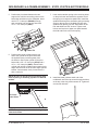
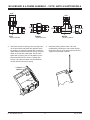
MOLDBOARD & A-FRAME ASSEMBLY – 810TR, 8100TR & 8611TR MODELS
5. Position the pivot beam between the two
support ribs until the connecting points on the
beam align with those on the snowplow. Insert
one 3/4" x 3" clevis pin (B50069) through
each mounting hole and secure them with
1/4" x 1-1/2" cotter pin (90601).
7.
Hook each extension spring to the receiving holes
on the pivot beam and attach the opposite end of
the spring to its respective spade bolts. Install the
spade bolts through the extension spring mounting
angle on the top rear of the blade. Secure each
spade bolt by placing one 5/8" flat washer on the
bolt and thread one 5/8" locknut. Tighten each
locknut until a piece of paper can pass between
the third and fourth coils on the spring.
Clevis
Pin
Cotter Pin
6. Position each angle cylinder with the rod
end of the cylinder in the pivot beam and
the hydraulic hose port facing away from
the A-frame. Secure the cylinder to the pivot
beam with a 3/4" x 5" clevis pin (95739) and a
1/4" x 1-1/2" cotter pin (90601). Extend each
cylinder rod until the cylinder base mounting hole
aligns with the hole on the A-frame angle cylinder
bracket. Insert another clevis pin and secure it
with a cotter pin.
NOTE: Be sure to use the proper mounting point
when replacing or installing cylinders on 8611TR
models.
8. Install the blade guides at each end of the
moldboard. Insert the cap screw through the holes
at the top of the wing reinforcement rib. Tighten all
screws with locknuts.
8611 Uses
Outer Holes
NOTE: The cylinder ports should be facing away
from the A-frame.
Lit. No. B64092, Rev. 06
14
July 15, 2012
MOLDBOARD & A-FRAME ASSEMBLY – 810TR, 8100TR & 8611TR MODELS
9. Assemble the manifold. Each of the hose ports on
the manifold is covered with stretch wrap. Remove
the wrap and install adapter (56695) in ports #1, 2,
7, 8, 9 and 10. Tighten fittings per torque chart.
NOTE: When handling the manifold, hold the
manifold at the sides of the block. Never handle
the manifold by coils. Doing so can cause a
solenoid cartridge to bend, causing the cartridge
to stick when activated.
12. Route the hydraulic hose groupings from the pivot
beam to the access holes located on the sides of
the A-frame. Connect the hoses to their respective
adapters on the manifold.
7
1
10
8
2
9
13. Remove the dust cap from both of the
hydraulic angle cylinder ports and attach one
9/16" 90° adjustable elbow ORB adapter (40571)
to each port. Each adapter should be angled
toward the top of the moldboard. Connect one
3/8" x 26" (36" for 8611) hydraulic hose (B60223
or B60224) to each angle cylinder adapter. Be
careful not to overtighten the hose connections.
Tighten fittings and hoses per torque chart.
14. Connect the hoses to their respective adapters on
the manifold. Tighten hoses per torque chart.
NOTE: DO NOT let any foreign objects enter
into the open ports. The valves can become
contaminated and greatly hinder the snowplow's
performance. Torque to proper specifications.
15. Install adapter (B60340) to port "T" on the
manifold. Connect a 1/2" x 115" hydraulic hose
(B60531) to the "T" adapter, and connect
3/8" x 115" hydraulic hoses (B60473) to the
"P2" and "P3" adapters. Tighten fittings and hoses
per torque chart.
NOTE: All ports are identified by a stamped
number on the manifold. The numbers also
identify the hydraulic functions, which can be
referenced on the label under the manifold cover.
10. Remove the A-frame cover to gain access to the
inside of the manifold compartment.
11. Attach the manifold to the A-frame using cap
screws (B61514), washers (29233) and locknuts
(B61034).
P3
T
8611TR
Model
Lit. No. B64092, Rev. 06
Manifold
Mount Holes
P2
15
July 15, 2012
MOLDBOARD & A-FRAME ASSEMBLY – 760TR, 860TR & 8600TR MODELS
1.
Position the front (top) hole in the A-frame with
the middle hole in the pivot beam. Insert cap
screw (B61331 for 760TR; 50605 for 860TR
and 8600TR) through the top, and secure on the
bottom with washer (B61203) and nut (B61008).
For 8600TR model: Insert one bushing (42410)
through each mounting hole and secure it with a
3/8' x 1-1/2" cap screw (66439) and 3/8" locknut
(91333).
2. Position the pivot beam and A-frame near the
mount locations at the rear of the blade. Position
the pivot beam between the two support ribs until
the connecting points on the beam align with
those on the snowplow.
Bushing
3/8" x 1-1/2"
Cap Screw
3/8"
Locknut
For 6760TR and 860TR models: Insert one
bushing (B16536) through each mounting hole
and secure them with retaining rings (B61616).
Retaining
Ring
Pivot Beam
3. Position each angle cylinder with the rod end of the
cylinder in the pivot beam and the hydraulic hose
port facing away from the A-frame. Secure the
cylinder to the pivot beam with a 3/4" x 5" clevis
pin (95739) and a 1/4" x 1-1/2" cotter pin (90601).
Extend each cylinder rod until the cylinder base
mounting hole aligns with the hole on the A-frame
angle cylinder bracket. Insert another clevis pin
and secure it with a cotter pin.
Bushing
NOTE: The cylinder ports should be facing away
from the A-frame.
Retaining
Ring
Lit. No. B64092, Rev. 06
16
July 15, 2012
MOLDBOARD & A-FRAME ASSEMBLY – 760TR, 860TR & 8600TR MODELS
9/16"
9/16"
3/4"
9/16"
9/16"
B60403
• Manifold Ports
40571
• Angle Cylinders
4. Hook each extension spring to the receiving holes
on the pivot beam and attach the opposite end of
the spring to its respective spade bolts. Install the
spade bolts through the extension spring mounting
angle on the top rear of the blade. Secure each
spade bolt by placing one 5/8" flat washer on the
bolt and thread one 5/8" locknut. Tighten each
locknut until a piece of paper can pass between
the 3rd and 4th coils on the spring.
25/32"
17/32"
B60539
• Angle Cylinders
5. Install the blade guides at each end of the
moldboard by inserting the cap screws through
the holes at the top of the wing reinforcement rib.
Tighten all screws with locknuts.
Locknut
Washer
Spade
Bolt
Spring
Lit. No. B64092, Rev. 06
17
July 15, 2012
MOLDBOARD & A-FRAME ASSEMBLY – 760TR, 860TR & 8600TR MODELS
6. Assemble the manifold. Each of the hose ports on
the manifold is covered with stretch wrap. Remove
the wrap and install adapter (B60403) in both
ports. Tighten fittings per torque chart.
10. Reinstall A-frame cover by aligning the holes in
the cover with those on the A-frame and securing
it with 3/8" x 1-1/2" cap screws and 3/8" washers.
11. Remove the dust cap from both of the
hydraulic angle cylinder ports and attach one
9/16" 90° adjustable elbow ORB adapter (40571)
to each port. Each adapter should be angled
toward the top of the moldboard. Connect one run
tee (B60539) to each elbow.
NOTE: DO NOT let any foreign objects enter
into the open ports. The valves can become
contaminated and greatly hinder the snowplow's
performance. Torque to proper specifications.
NOTE: All of the hydraulic adapters can be found
packaged with the manifold assembly.
7.
12. Connect one hydraulic hose from the A-frame
compartment to each angle cylinder. Be careful
not to overtighten the hose connections. Tighten
fittings and hoses per torque chart.
Remove the A-frame cover to gain access to the
inside of the manifold compartment.
13. Connect one 3/8" x 115" hydraulic hose (B60473)
to each angle cylinder run tee. Be careful not to
overtighten the hose connections. Tighten fittings
and hoses per torque chart.
8. Attach the manifold to the A-frame using
cap screws (94498), washers (B61039) and
locknuts (91331).
NOTE: When handling the manifold, hold the
manifold at the sides of the block.
14. On each side of the blade, insert a cable through
the pivot bushing from the center, then pin the
cable onto the A-frame extensions. Slide the cable
through the spring, and add a washer (760TR and
860TR models only) and nut. Adjust the nuts on
the cable at full angle so that the wing stops just
touch the outside moldboard ribs.
9. Connect one 3/8" x 36" hydraulic hose (B60224)
to each adapter on the manifold. Route the hoses
out through the access holes located on the
sides of the A-frame, with one hose going out
each side. Be careful not to overtighten the hose
connections. Tighten hoses and fittings per torque
chart.
NOTE: Too much adjustment will cause the wings
to stop before the snowplow is fully angled and
could stretch the cables.
NOTE: Review the label on each hose for the
appropriate part number.
Lit. No. B64092, Rev. 06
Adjust the cables with the blade centered, then
angle the blade to see if the stops are touching.
Attach a jam nut to lock in the cable adjustment.
18
July 15, 2012
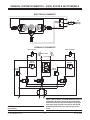
GENERAL SYSTEM SCHEMATICS – 810TR, 8100TR & 8611TR MODELS
ELECTRICAL SCHEMATIC
To
Tractor
Wiring
S1
S2
S3
HYDRAULIC SCHEMATIC
LEFT SLIDE BOX
RIGHT SLIDE BOX
RIGHT ANGLE
LEFT ANGLE
8
7
1
2
3000 PSI
1500 PSI
(2650 PSI)
RV2
1700 PSI
(2800 PSI)
9
10
1500 PSI
(2650 PSI)
1700 PSI
(2800 PSI)
RV3
RV5
RV1
RV4
S1
T
S3
S2
P2
P3
NOTE: Where applicable, Model 8611 values are in
parentheses.
Lit. No. B64092, Rev. 06
19
NOTE: 760TR, 860TR, and 8600TR Models have no
solenoids and require no electrical connections
between the tractor and the snowplow. One hose
from each angle cylinder connects to the 760TR
and 860TR manifolds to provide wing pressure
relief.
July 15, 2012
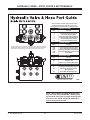
HYDRAULIC GUIDE – 810TR, 8100TR & 8611TR MODELS
RV1
Recommended for machines equipped with auxiliary
hydraulics having a flow rated at 4–30 gallons per
minute (gpm) and a maximum pressure rating of 3,000psi.
RV4
RV5
HYDRAULIC HOSES
RV2
RV3
S1
S2
S3
Port
Function
1
2
7
8
9
10
Passenger-Side Angle Cylinder
Driver-Side Angle Cylinder
Passenger-Side Slide Box Retract
Passenger-Side Slide Box Extend
Driver-Side Slide Box Extend
Driver-Side Slide Box Retract
RELIEF VALVES
NOTE: Pressure lines P2 & P3 and return line / auxiliary wing relief T are not
illustrated. All three are located on the left side of the manifold in the diagram
shown above. Pressure lines P2 & P3 also contain orifice check valves.
Valve
Function
RV1
RV2
RV3
RV4
RV5
Driver-Side Wing Pressure Relief
Driver-Side Wing Anti-Cavitation
Passenger-Side Wing Anti-Cavitation
Passenger-Side Wing Pressure Relief
Angle Relief
PRESSURE LINES
Line
Function
P2
P3
T
Pressure Line
Pressure Line
Return Line / Auxiliary Wing Relief
NOTE: Energize the following solenoids for the functions:
7
1
10
8
2
9
S1
S2
S3
Passenger-Side Slide Box Cylinder
Passenger- & Driver-Side Slide
Box Cylinders
Driver-Side Slide Box Cylinder
Milwaukee, Wisconsin 53224
29328
NOTE: 760TR, 860TR, and 8600TR Models have
only one relief valve (PN B60168 – 3000 psi) and
no solenoids. One hose from each angle cylinder
connects to the 760TR and 860TR manifolds to
provide wing pressure relief.
Lit. No. B64092, Rev. 06
20
July 15, 2012
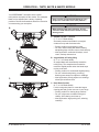
OSCILLATING PLATE ASSEMBLY – ALL MODELS
1.
Attach the oscillating plate to the tractor now.
The tractor-specific hooks come pre-welded
on the oscillating plate assembly. Refer to the
illustrations below for hook identification. If welding
the tractor-specific hooks is necessary, measure
the distance on the tractor to determine appropriate
placement of the hooks on the oscillating plate. Refer
to the illustration below for weld specifications.
2. Route the loose hoses (from Ports "T", "P2" and
"P3" on 810TR and 8611TR models; from angle
rams on 760TR, 860TR and 8600TR models)
through the clamp on left side of oscillating plate.
NOTE: Route the hoses so they do not get
pinched during use.
1/4
1/4
1/4
1/4
D
TYP
B
1/4
TYP
B
1/4
TYP
TYP
D
1/4
2.0-8.5
1/4
2.0-8.5
TYP
TYP
B70201
Kramer High
70229
O&K Upper
B70225
Trima
B70237
Volvo
B70202
3-Point Hitch
70243
Euro
Upper
70244
Euro
Lower
B70221
Kunta
Lit. No. B64092, Rev. 06
70227
O&K
Lower
B70233
Vila
21
B70242
Zettelmeyer
July 15, 2012
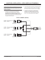
ELECTRICAL INSTALLATION – 810TR, 8100TR & 8611TR MODELS
2. Connect the tractor end of the coil harness to the
tractor's auxiliary electrical system according to
the vehicle's owner's manual or service manual.
NOTE: 760TR, 860TR and 8600TR Models do not
require electrical connections between the tractor
and the snowplow.
1.
3. Complete the assembly by reattaching the
A-frame cover. Align the holes in the cover
with those on the A-frame and secure it with
3/8" x 1-1/2" cap screws and 3/8" washers.
Connect the coil harness to the solenoids
according to the illustration below. Feed the
opposite end of the harness through the top
access hole in the A-frame, and route the harness
into the tractor making sure to secure it so it will
not get pinched during use.
TR COIL HARNESS (B62264)
1
2
1) WHT – S1 (left slide box)
2) BLK – Ground
(End View)
1
BLK
WHT
2
1) RED – S2 (angle isolation)
2) BLK – Ground
GRN
To
Tractor
Wiring
(End View)
1
2
1) GRN – S3 (right wing)
2) BLK – Ground
(End View)
Lit. No. B64092, Rev. 06
22
July 15, 2012
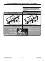
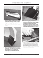
MOUNTING & DISMOUNTING INSTRUCTIONS – ALL MODELS
Prior to operating your snowplow, review the Mount
and Dismount Instructions label on the back of the
driver-side moldboard.
NOTE: If at any time the Mount and Dismount
Instructions label, or any other label attached
to your snowplow, becomes illegible, promptly
replace it.
MOUNT INSTRUCTIONS
DISMOUNT INSTRUCTIONS
Read Owner's Manual for Complete Instructions.
Read Owner's Manual for Complete Instructions.
Hook
Hook
Oscillating
Plate
Oscillating
Plate
Lever
Receiving
Hole
Lever
Receiving
Hole
WARNING: Keep fingers away from snowplow and tractor mounting points. Follow tractor labeling and owner's manual.
• Position the tractor close to the snowplow and align the mount points on the tractor
with the hooks on the back oscillating plate of the snowplow.
• Slowly raise the tractor mounting points until the tractor engages the snowplow
hooks. Turn the engine OFF.
• Engage both locking levers on the tractor by rotating
each handle 90° into a horizontal position. The tractor
locking levers shall insert into the snowplow
lever receiving holes.
• Attach all hydraulic hoses on the snowplow to the
auxiliary hydraulic connections located on the tractor.
On some tractor models, it may be necessary to initiate
an auxiliary hydraulic switch on the tractor prior to
operating the snowplow.
• Connect the snowplow wire harness to either the pistol
grip control or auxiliary electrical connection on the
tractor.
• Lower the snowplow on a flat, level surface and turn the engine OFF.
• Disconnect the snowplow wire harness from the tractor.
• Disconnect all hydraulic hoses on the snowplow from the auxiliary hydraulic
connections located on the tractor.
• Disengage both locking levers on the tractor by rotating
each handle 90° into a vertical position. The tractor
locking levers shall withdraw from the snowplow lever
receiving holes.
• Turn the engine ON. Slowly lower the tractor mounting
points until the tractor clears the snowplow hooks.
• Back the tractor away slowly.
44832
U.S. Patents 5,638,618; 5,899,007; 6,178,669; 6,276,076; 6,393,737; 6,408,549; 6,412,199; 6,442,877; 6,615,513; CAN Patents 2,184,922; 2,229,783; 2,259,508; 2,358,145; 2,358,354; 2,466,195; and other patents pending.
Lit. No. B64092, Rev. 06
23
July 15, 2012
TESTING YOUR SNOWPLOW – ALL MODELS
1.
To test all of the functions, your snowplow needs
to be properly attached to the tractor. Refer to the
Mounting and Dismounting label on the back of
the snowplow.
NOTE: Depending on the tractor model, it may
be necessary to turn ON the tractor's auxiliary
hydraulic switch prior to operating the snowplow.
Activate each function of the snowplow.
2. Complete the hydraulic connections with the
tractor turned OFF.
For 810TR and 8611TR Models: Extend and
retract the driver-side wing a few times, then
extend and retract the passenger-side wing. Angle
the blade left and right a few times.
NOTE: Due to the various makes and models of
tractors available, hydraulic couplings for the
auxiliary hydraulic connections are not provided.
Consult your tractor's owner's manual for the
appropriate couplings needed.
For 760TR, 860TR, and 8600TR Models: Angle
the blade left and right a few times.
For 810TR and 8611TR Models: Connect the
couplings to the loose hoses coming from the
pressure ports ("P2" and "P3") and the tank port
("T") on the manifold.
Upon initiating the snowplow functions, you may
notice a snowplow function is slow or delayed.
The hydraulic fluid is filling the cylinders and
replacing air in the system. Monitor the hydraulic
fluid level in your tractor and fill as necessary.
For 760TR, 860TR, and 8600TR Models:
Connect the couplings to the loose hoses coming
from each ram.
NOTE: This snowplow uses the tractor controls
for an emergency stop. See tractor manual for
details.
Complete the hydraulic installation by making the
appropriate connections at the tractor.
3. Start the tractor and begin to initiate the blade
functions.
Lit. No. B64092, Rev. 06
24
July 15, 2012
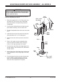
ADJUSTABLE SNOWPLOW SHOE ASSEMBLY – ALL MODELS
WARNING
Blade can drop unexpectedly. Place the blade
on jack stands. Failure to do so could result in
serious personal injury.
With the snowplow fully assembled and operational,
install the adjustable plow shoes.
1.
5/16"
Locknut
5/16" x 1-3/4"
Cap Screw
Raise the snowplow 6" to 12" off the ground, turn
the tractor OFF and, from in front of the blade,
place jack stands or sturdy blocking under the
cutting edge.
3/4"
Washer
2. Turn the tractor ON and lower the blade onto the
jack stands or blocking. Turn the tractor OFF.
3. Thread the adjustable shoe rod into the inner shoe
stem.
Handle
Outer
Shoe
Stem
4. Attach the shoe to the inner shoe stem using the
shoe pin and two 1/4" x 1-1/2" spring pins.
5. Slide the inner shoe stem up into the outer shoe
stem.
Rod
6. Place a 3/4" washer onto the adjustable shoe
rod, then attach the handle to the rod using a
5/16" x 1-3/4" cap screw and 5/16" locknut.
7.
Inner
Shoe
Stem
Turn the tractor ON. Raise the blade slightly from
the jack stands. Turn the tractor OFF and remove
the jack stands.
Shoe
Shoe
Pin
8. Stand 8 feet clear of the blade when checking the
height adjustment of the cutting edge to the road
surface.
9. Turn the handle clockwise to lower the shoe and
turn the handle counterclockwise to raise the
shoe. Lock the handle down against the outer
shoe stem when adjustment is complete.
Lit. No. B64092, Rev. 06
1/4" x 1-1/2"
Spring Pin
25
July 15, 2012
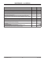
MAINTENANCE – ALL MODELS
Maintenance
Periodically
Check fasteners for tightness. Torque to specifications.
X
Check hoses for wear and leaks.
X
Check cylinders for leaks; inspect rod ends for corrosion & pitting.
X
Check cables for wear or fraying (760TR and 860TR Models only).
X
Lubricate all exposed cylinder rod ends with liquid white lithium grease to prevent corrosion.
Check cutting edges and plow shoes for wear.
X
Clean and lubricate all electrical plugs and connections with dielectric grease. Clean and
X
install all dust caps prior to storing.
Lubricate all pins and bushings, inner slide box and A-frame latch with NLGI Grade
2 multi-purpose lithium complex grease with molybdenum (MPGM) to maintain consistent
X
operation.
Clean and paint all scratches or exposed metal with BLIZZARD ® touch-up paint.
X
Check the hydraulic fluid level. Never mix different types of fluid.
X
Change the hydraulic fluid as specified in your tractor owner's manual.
Check the trip spring adjustment. Properly adjusted tension will allow a sheet of paper to
X
pass between the 3rd and 4th coils of the spring.
Adjust the wing spring as needed or install an optional second extension spring for increased
X
return speed.
Pressure wash and dry the entire snowplow prior to storing.
Cover the snowplow with a tarp if stored outside. This will protect your plow from sun fading
and inclement weather which can lead to accelerated corrosion.
Lit. No. B64092, Rev. 06
26
Yearly
X
X
X
X
X
X
X
July 15, 2012
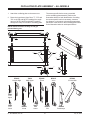
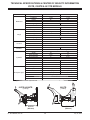
REMOVING FROM STORAGE & LIFTING
REMOVING FROM STORAGE
LIFTING
1.
To lift and move this snowplow, attach chain fall
grab hooks to outside pivot beam area shown.
Always follow recommended lift warnings and
procedures. See the following page for snowplow
weights and dimensions.
Perform all regular maintenance.
2. Replace the hydraulic fluid in the hydraulic system.
Prolonged storage could result in condensation
build-up.
3. Follow the mounting procedure on the Mounting
and Dismounting label.
4. Initiate all of the functions and test before using.
Lifting Points
(both sides)
Lit. No. B64092, Rev. 06
27
July 15, 2012
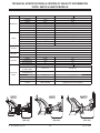
TECHNICAL SPECIFICATIONS & CENTER OF GRAVITY INFORMATION
810TR, 8100TR & 8611TR MODELS
Part
Moldboard
Wings
A-Frame
Manifold
Cylinders
Snowplow Specs
Specification
Length
Thickness
Height
Reinforcement
Cutting Edge
Finish
Trip Mechanism
Length
Thickness
Height
Reinforcement
Cutting Edge
Finish
Material
Cover
Finish
Construction
Valves
Angle Cylinders
Stroke
Ram Diameter
Bore Diameter
Slide Box Cylinders
Stroke
Ram Diameter
Bore Diameter
Weight*
Compact Width
WIDE PASS™ Width
BUCKET BLADE™ Width
Adjustable Plow Shoes
Mount Mechanism
Control
810TR & 8100TR
8611TR
96" (8')
102" (8'-6")
12 ga
11 ga
31"
34"
4 Ribs @ 1/4"
1/2" x 6"
5/8" x 6"
Powder Coat White
(4) 3/8" Hooked Extension (6) 3/8" Hooked Extension
12"
23"
11 ga
7 ga
31"
34"
1 Rib @ 1/4"
1/4" x 10" T1
3/8" x 12-1/2" T1
Powder Coat White
1/4" & 5/16" Mild Steel
1/4" Mild Steel w/Non-Skid Texture
Powder Coat Black
Red Anodized Aluminum
Black Anodized Aluminum
Electro-Hydraulic Cartridge
2
10"
12"
1-3/4"
2"
2"
2-1/4"
2
13-15/16"
18-7/16"
1"
1-1/8"
1-1/2"
1-3/4"
1132 lb
1728 lb
96" (8')
102" (8'-6")
120" (10')
132" (11'-3")
111" (9'-3")
118" (9'-10")
(2) Heavy-Duty Cast Steel
Universal Attachment Plate
Wired into Tractor System
* Weight does not include hydraulic fluid.
810TR & 8100TR
8611TR
(1132 lb)
(1728 lb)
23.75 in
(603 mm)
Lit. No. B64092, Rev. 06
27.92 in
(709 mm)
28
July 15, 2012
TECHNICAL SPECIFICATIONS & CENTER OF GRAVITY INFORMATION
760TR, 860TR & 8600TR MODELS
Part
Moldboard
Wings
A-Frame
Manifold
Cylinders
Snowplow
Specs
Specification
760TR
860TR
8600TR
Length
92" (7'-6")
102" (8'-6")
Thickness
12 ga
12 ga
Height
25.5"
29.5"
Reinforcement
4 Ribs @ 1/4"
4 Ribs @ 1/4"
Cutting Edge
3/8" x 6"
1/2" x 6"
Finish
Powder Coat White
Powder Coat White
Trip Mechanism Springs (3) 3/8" Hooked Extension
(4) 3/8" Hooked Extension
Length
15.5"
17.5"
Thickness
12 ga
12 ga
Height
25.5"
29.5"
Reinforcement
2 Ribs @ 3/16"
2 Ribs @ 3/16"
Cutting Edge
3/8" x 6"
1/2" x 6"
Finish
Powder Coat White
Powder Coat White
Material
1/4" & 5/16" Mild Steel
Cover
1/4" Mild Steel w/Non-Skid Texture
Finish
Powder Coat Black
Construction
Black Anodized Aluminum
Valves
Angle Cylinders
Stroke
Rod Diameter
Bore Diameter
Weight*
BUCKET BLADE™
Position Width
Angle Width
w/Trailing Wing
Back Blade Width
Adjustable Plow Shoes
Mount Mechanism
Control
N/A
2
9-3/8"
1-3/4"
2"
895 lb
2
10"
1-3/4"
2"
944 lb
885 lb
91" (7'-7")
103" (8'-7")
79" (6'-7")
94" (7'-10")
103" (8'-7")
(2) Heavy-Duty Cast Steel
Universal Attachment Plate
Hydraulic from
Tractor System
117" (9'-9")
(2) Heavy-Duty Cast Steel
Universal Attachment Plate
Hydraulic from Tractor System
* Weight does not include hydraulic fluid.
760TR
860TR
8600TR
(895 lb)
(944 lb)
(885 lb)
21.25 in
(540 mm)
18.19 in
(462 mm)
Lit. No. B64092, Rev. 06
29
24.38 in
(619 mm)
July 15, 2012
TROUBLESHOOTING – ALL MODELS
library of service information to assist the qualified
mechanic with repair.
If you have followed all of the guidelines in the
Maintenance Section of this manual and cannot
resolve issues with the operation of your BLIZZARD®
snowplow, contact one of our authorized outlets
for repair information, or visit us online at
www.blizzardplows.com. Our Web site has a complete
listing of authorized outlets in your area as well as a
Lit. No. B64092, Rev. 06
Blizzard does not recommend repairs by other than
our authorized outlets. Failure to use an authorized
outlet could affect the warranty coverage on your
snowplow.
30
July 15, 2012
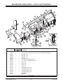
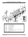
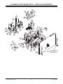
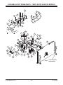
MOLDBOARD & WING PARTS – 810TR & 8611TR MODELS
8
7
20
17
15
23
19
52
44
46
43
2
4
18
24
10
54
26
53
6
34
22
29
48
47
35
37
5
3
14
36
45
20
41
49
55
12
28
11
1
32
30
27
21
9
31
38
13
27
29
40
33
16
50
51
38A
39
42
25
Item
1
2
3
4
5
6
7
8
9
10
Part
B61681
B11989
B50057
B50075
B50058
B50074
B51009
B13307
B51042
B51100
B51043
B51101
B51047
B51070
B51048
B51069
B52149
B52142
Qty
810TR 8611TR
4
4
2
2
1
–
–
1
1
–
–
1
2
–
–
2
1
–
–
1
1
–
–
1
1
–
–
1
1
–
–
1
1
–
–
1
Lit. No. B64092, Rev. 06
Description
Pin, Wing Stop
5/8 x 11-1/2 Pin, Hydraulic Cylinder Base End - Slide Box Extend/Retract
Slide Box – DS
Slide Box – DS
Slide Box – PS
Slide Box – PS
3/4 x 9 Pin, Wing/Slide Box Pivot
1 x 11-1/8 Pin, Wing/Slide Box Pivot
Wing – DS
Wing – DS
Wing – PS
Wing – PS
Cutting Edge, Wing – PS
Cutting Edge, Wing – PS
Cutting Edge, Wing – DS
Cutting Edge, Wing – DS
Moldboard
Moldboard
G = Grade
31
July 15, 2012
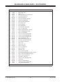
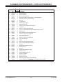
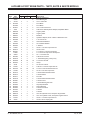
MOLDBOARD & WING PARTS – 810TR & 8611TR MODELS
Item
11
12
13
14
15
16
17
18
19
20
21
22
23
24
25
26
27
28
29
30
31
32
33
34
35
36
37
38A
38
39
40
41
42
43
44
45
Part
B60007
56695
B60347
B60207
B61028
B61030
90576
96325
96329
96326
96330
23039
B61187
91337
B61196
B61198
B61292
B52139
63575
B61341
B61361
B61362
B61365
B61383
B61384
B61385
B61398
23039
B61400
B61416
B61418
B61360
B61419
B61361
66435
B63160
B70249
B70251
B70261
B70262
B70281
B70285
44832
59900
29593
Qty
810TR 8611TR
4
–
–
4
2
–
–
2
2
2
2
2
4
6
1
–
–
1
1
–
–
1
4
6
4
6
6
8
8
8
2
2
1
–
–
1
2
2
4
4
2
–
–
2
14
14
4
4
6
6
2
2
2
–
–
2
2
2
2
2
2
–
–
2
2
–
–
2
2
2
1
1
2
2
2
2
2
2
2
2
2
2
2
2
1
1
1
1
2
2
Lit. No. B64092, Rev. 06
Description
9/16-18 Male ORB Hydraulic Adapter
45° Elbow –6M O-Ring/MJIC
Hydraulic Cylinder, Slide Box Extend/Retract
Hydraulic Cylinder, Slide Box Extend/Retract
1/4 x 1-1/4 Pin
1/8 x 2-5/8 Hair Cotter Pin
5/8 Hardened Washer
Label, Wing – DS
Label, Wing – DS
Label, Wing – PS
Label, Wing – PS
Trip Spring
5/8-11 x 6-3/8 Spade Bolt G8
5/8-11 Locknut
1/2-13 x 1-1/2 Carriage Bolt G8
5/8 ID, 3/4 OD x 1 Cap, Black Vinyl
Cutting Edge
Cutting Edge
3/4 Hardened Washer
1/4 x 1-1/2 Spring Pin
1/2-13 x 5-1/2 Carriage Bolt G8
1/2-13 x 6-1/2 Carriage Bolt G8
1/2-13 Flanged Locknut
5/16-18 x 2-1/4 Hex Cap Screw G8
5/16-18 Locknut G8
5/8 x 3 Clevis Pin
13 x 2 x 5/16 Extension Spring
Spring
1/8 NPT Grease Fitting
5/8-11 x 7-3/8 Spade Bolt G8
1/2-13 x 3-1/2 Carriage Bolt G8
1/2-13 x 5 Carriage Bolt G8
1/2-13 x 4-1/2 Carriage Bolt G8
1/2-13 x 5-1/2 Carriage Bolt G8
5/16-18 x 1-3/4 Hex Cap Screw G5
Label, Center Moldboard (BLZ 1070)
Shoe Assembly
Shoe Stem, Inner
Shoe, Adjustable
Plow Shoe Rod, Adjustable
Plow Shoe Handle, Adjustable
Plow Shoe Pin, Adjustable
Label – Mount & Dismount
Label – Warning/Caution
Label – Multiple Pinch Points (BLZ 1068)
G = Grade
32
July 15, 2012
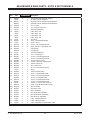
MOLDBOARD & WING PARTS – 810TR & 8611TR MODELS
Item
46
47
48
49
50
51
52
53
54
55
Part
B61049
68494
91332
B60224
96192
96190
90238
80238
91335
91337
90572
90576
29256
Qty
810TR 8611TR
1
1
4
4
4
4
4
4
2
2
2
2
7
–
–
7
7
–
–
7
7
–
–
7
2
2
Lit. No. B64092, Rev. 06
Description
Snowplow Guide Assembly (2)
5/16-18 x 1 Hex Cap Screw G5
5/16-18 Locknut Topring
3/8 x 36 Hydraulic Hose, Slide Box Extend/Retract
Bolt-On Jack
Bolt-On Jack Assembly, complete
1/2-13 x 1-3/4 Carriage Bolt G8
5/8-11 x 2 Carriage Bolt G8
1/2-13 Hex Locknut Topring GB
5/8-13 Hex Locknut Topring GB
1/2 Hardened Flat Washer
5/8 Hardened Flat Washer
Label – Foot Crush Hazard
G = Grade
33
July 15, 2012
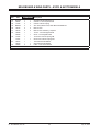
MOLDBOARD & WING PARTS – 8100TR MODEL
1
16
15
44
49
51
3
35
12
37
5
2
36
4
14
10
13
19
18
33
32
48
42
38
31
39
45
29
44
43
47
7
34
46
9
22
23
24
Qty
1
1
1
1
1
8
14
2
2
2
2
2
1
52
6
28
25
27
Description
Moldboard
Label – Information (Warning)
Label – POWER PLOW™ Center
Label – TR Mount/Dismount
1/2" Moldboard Cutting Edge
1/2-13 x 1-1/2 Carriage Bolt G8
1/2-13 Flanged Locknut
3/4-10 x 1-1/2 Screw
3/4-10 Hex Locknut G8
5/8 x 11-1/2 Pin, Hydraulic Cylinder Base End – Slide Box Extend/Retract
1/8 x 2-5/8 Hair Cotter Pin
5/8 ID, 3/4 OD x 1 Black Vinyl Cap
Slide Box – PS
ns = not shown
Lit. No. B64092, Rev. 06
53
26
7
Part
41173
59900
B63160
44832
B61292
B61196
B61365
B61618
B61593
B11989
B61030
B61198
B55066
11
8
30
Item
1
2
3
4
5
6
7
8
9
10
11
12
13
50
20
21
41
40
17
G = Grade
34
‡ = Accessory Only
July 15, 2012
MOLDBOARD & WING PARTS – 8100TR MODEL
Item
Part
14
15
16
17
18
19
20
21
22
23
24
25
26
27
28
29
30
31
32
33
34
35
36
37
38
39
40
41
42
43
44
45
46
47
48
49
50
51
52
53
B51047
96326
40740
66435
63575
B61384
B70281
B61400
B70262
B70251
B70249
B70261
B70285
B61341
96190
29593
90490
B61418
B61419
B61622
B51048
B61049
68494
91332
40739
96325
B61385
90601
B55042
B55065
91337
B60347
B61167
29256
50639
90238
23039
B61416
91335
90572
Qty Description
1
1
1
2
2
6
2
2
2
2
2
2
2
4
2
4
2
2
2
2
1
1
4
4
1
1
2
2
2
1
6
2
2
2
2
7
4
4
7
7
Wing Cutting Edge – PS
Wing Label – PS
Wing – PS
5/16-18 x 1-3/4 Hex Cap Screw G5
3/4 Hardened Washer
5/16-18 Locknut GC
Plow Shoe Handle, Adjustable
1/8 NPT Grease Fitting
Plow Shoe Rod, Adjustable
Shoe Stem, Inner
Shoe Assembly
Shoe, Adjustable
Plow Shoe Pin, Adjustable
1/4 x 1-1/2 Spring Pin
Bolt-On Jack Assembly, Complete
Label – Multiple Pinch Points
5/8-11 x 4 Eyebolt G2
1/2-13 x 3-1/2 Carriage Bolt G8
1/2-13 x 4-1/2 Carriage Bolt G8
1/2-13 x 5-3/4 Carriage Bolt G8
Wing Cutting Edge – DS
Plow Guide Assembly (set of 2)
5/16-18 x 1 Hex Cap Screw G5
5/16-18 Hex Locknut GB
Wing – DS
Wing Label – DS
5/8 x 3 Clevis Pin
1/4 x 1-1/2 Cotter Pin
Wing Pivot Pin
Slide Box – DS
5/8-11 Hex Locknut GB
Slide Box Extend/Retract Hydraulic Cylinder
3/8 x 2-5/8 x 12-1/2 Extension Spring
Label – Foot Crush Hazard
Wear Strip – Wing Top
1/2-13 x 1-3/4 Carriage Bolt G8
Trip Spring
5/8-11 x 7-3/8 Eyebolt G2
1/2-13 Hex Locknut Topring GB
1/2 Hardened Flat Washer
ns = not shown
Lit. No. B64092, Rev. 06
G = Grade
35
‡ = Accessory Only
July 15, 2012
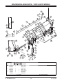
MOLDBOARD & WING PARTS – 760TR & 860TR MODELS
25
8
29
2
26
5
8
6
41
40
7
17
31
42
24
8
32
9
10
18
13
16
28
4
14
44
43
15
39
30
23
37
11
22
20
36
1
3
11
15
34
19
33
22
38
43
21
27
11
12
35
11
Item
1
2
3
4
Qty
Part
760TR 860TR
B53021
1
–
B53062-1
–
1
B53033
1
–
B53075-1
–
1
B53076
2
2
B53092
1
–
B53091
–
1
Description
Wing – DS
Wing – DS
Wing – PS
Wing – PS
Spring Guide
Moldboard
Moldboard
G = Grade
Lit. No. B64092, Rev. 06
SS = Stainless Steel
36
July 15, 2012
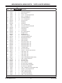
MOLDBOARD & WING PARTS – 760TR & 860TR MODELS
Item
Part
5
6
7
8
9
10
11
12
13
B61049
90576
91337
90238
90490
63575
B61341
B61343
B61351
B61099
90601
91335
B61400
B61561
B61570
B61563
B61564
B61572
69695
B61576
B61577
B61578
B61573
B61608
B61610
B61609
B61611
B61614
B61615
66435
B63171
96328
96323
96327
B63175
44832
B70249
B70251
B70261
B70262
B70281
B70285
29593
68494
91332
59900
90572
29256
14
15
16
17
18
19
20
21
22
23
24
25
26
27
28
29
30
31
32
33
34
35
36
37
38
39
40
41
42
43
44
Qty
760TR 860TR Description
1
3
3
10
3
2
10
2
3
–
2
10
2
1
–
2
2
–
2
2
4
2
–
1
–
1
–
2
2
2
1
–
1
–
1
1
2
2
2
2
2
2
2
4
4
1
10
2
Lit. No. B64092, Rev. 06
1
Plow Guide Assembly (2)
4
5/8 Hardened Washer
4
5/8-11 Locknut
11
1/2-13 x 1-3/4 Carriage Bolt G8
4
5/8-11 x 4 Eyebolt G2
2
3/4 Hardened Washer
10
1/4 x 1-1/2 Spring Pin
2
3/4-10 Hex Nut
–
Trip Spring
4
Trip Spring
2
1/4 x 1-1/2 Cotter Pin
11
1/2-13 Hex Locknut Topring GB
2
1/8 Grease Fitting
–
Cutting Edge
1
Cutting Edge
2
5/8 x 3-3/8 Clevis Pin
–
Wing Mount Pin
2
Wing Mount Pin
2
Compression Spring
2
3/4 Hardened Washer, SS
4
Wing Spring Mount Pin
–
Cable Assembly
2
Cable Assembly
–
Wing Cutting Edge – DS
1
Wing Cutting Edge – DS
–
Wing Cutting Edge – PS
1
Wing Cutting Edge – PS
2
1" Finishing Plug
2
3/4-10 Hex Jam Nut
2
5/16-18 x 1-3/4 Hex Cap Screw G5
–
Label, Wing – PS
1
Label, Wing – PS
–
Label, Wing – DS
1
Label, Wing – DS
1
Label, Center Moldboard (BLZ 1085)
1
Label – Mount & Dismount
2
Shoe Assembly
2
Shoe Stem, Inner
2
Shoe, Adjustable
2
Plow Shoe Rod, Adjustable
2
Plow Shoe Handle, Adjustable
2
Plow Shoe Pin, Adjustable
2
Label – Multiple Pinch Points (BLZ 1068)
4
5/16-18 x 1 Hex Cap Screw G5
4
5/16-18 Locknut Topring
1
Label – Warning/Caution
11
1/2 Hardened Flat Washer
2
Label – Foot Crush Hazard
G = Grade
37
SS = Stainless Steel
July 15, 2012
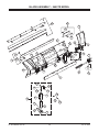
BLADE ASSEMBLY – 8600TR MODEL
14
42
26
29
28
4
1
32
25
12
20
24
27
3
23
30
22
18
31
2
28
4
20
21
15
13
19
19
16
41
7
6
10
9
8
38
11
5
37
39
40
35
33
36
34
Lit. No. B64092, Rev. 06
38
July 15, 2012
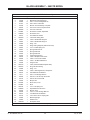
BLADE ASSEMBLY – 8600TR MODEL
42408 Blade Assembly
Item
1
2
3
4
5
6
7
8
9
10
11
ns
12
13
14
15
16
ns
18
19
20
21
22
23
24
25
26
27
28
29
30
31
32
33
34
35
36
37
38
39
40
41‡
42‡
ns‡
Part
Qty
42409
1
49799
1
63986
8
91337
14
96190
2
66435
2
B61384
2
B70281
2
B70262
2
63575
2
B61400
2
42941
1
42942
1
42385
1
42383
1
42943
2
42397
2
42392
1
42393
1
42725
2
29593
4
29256
2
44832
1
42396
2
B63175
1
B61614
2
42386
1
59900
1
90576
14
5572
6
66439
2
91333
2
42395
4
B70251
2
B70261
2
B61341
4
B70285
2
96192
2
90238
8
90572
8
91335
8
42382
1
42384
1
B52093
1
ns = not shown
Lit. No. B64092, Rev. 06
Description
Moldboard (w/labels)
Moldboard Cutting Edge Kit
5/8-11 x 2-1/2 Carriage Bolt G5
5/8-11 Hex Locknut GB
Bolt-On Jack Assembly, Complete
5/16-18 x1-3/4 hex Cap Screw G5
5/16-18 Locknut G8
Plow Shoe Handle, Adjustable
Plow Shoe Rod
3/4 Hardened Washer
1/8 Grease Fitting NPT
Label – Moldboard Wing DS
Label – Moldboard Wing PS
Wing – DS
Wing Cutting Edge Kit (both DS and PS)
1/4 x 1 Coiled Spring Pin
Spring Guide Pin Kit
Spring Guide DS
Spring Guide PS
Compression Spring
Label – Multiple Pinch Points
Label – Foot Crush Hazard
Label – TR Mount/Dismount
Hinge Pin Kit
Label, Center Moldboard (BLZ 1085)
Plug, Ø1.00 Finishing
Wing – PS
Label – Warning/Caution, Snowplows
5/8 Hardened Flat Washer
5/8-11 x 2 Carriage Bolt G5
3/8-16 x 1-1/2 Hex Cap Screw G5
3/8 -16 Hex Locknut GB
Bumper Kit
Shoe Stem, Inner
Shoe
1/4 x 1-1/2 Spring Pin
Adjustable Plow Shoe Pin
Bolt-On Jack
1/2-13 x 1-3/4 Carriage Bolt G8
1/2 Hardened Flat Washer
1/2-13 Hex Locknut Topring GB
Back Drag Edge
Deflector Kit
Snowplow Airfoil
‡ = Accessory Only
39
G = Grade
July 15, 2012
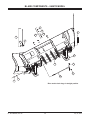
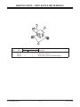
BLADE COMPONENTS – 8600TR MODEL
9
3
7*
11
10
13
14
15
8
5
12
6
4
2
1
* Pins used to lock wings in straight position
Lit. No. B64092, Rev. 06
40
July 15, 2012
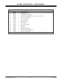
BLADE COMPONENTS – 8600TR MODEL
Blade Components
Item
1
2
3
4
5
6
7
8
9
10
11
12
13
14
15
Part
B61615
B61343
90576
42389
B61563
90601
42738
91962
91337
90490
50655
23039
B61049
68494
91332
Lit. No. B64092, Rev. 06
Qty
2
2
4
2
2
2
2
2
4
4
4
4
2
4
4
Description
3/4-10 Hex Jam Nut
3/4-10 Hex Nut
5/8 Hardened Flat Washer
Cable Assembly w/Hardware (incl. items 1, 2, 5 and 6)
Ø .625 x 2.33 Clevis Pin
1/4 x 1-1/2 Cotter Pin
3/4 x 9 Clevis Pin
1/8 Hairpin Cotter
5/8-11 Locknut
5/8-11 x 4 Eyebolt G2
Eyebolt Kit
Trip Spring
Blade Guide Assembly
5/16-18 x 1 Hex Cap Screw G5
5/16-18 Hex Locknut GB
SS = Stainless Steel
41
July 15, 2012
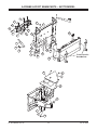
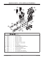
A-FRAME & PIVOT BEAM PARTS – 810TR & 8100TR MODELS
32
30
9
13
2
36
11
20
9
2
17
18
16
18
7
3
2
14
25
14
12
1
18
18
19
28
23
15
8
31
34
18
33
22
23
4
10
19
6
28
35
23
21
9
26
10
5
24
29
27
Lit. No. B64092, Rev. 06
42
Tractor-Specific
Hook Mounts
July 15, 2012
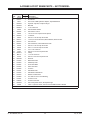
A-FRAME & PIVOT BEAM PARTS – 810TR & 8100TR MODELS
Item
1
2
3
4
5
6
7
8
9
10
11
12
13
14
15
16
17
18
19
20
21
22
23
24
25
26
27
28
29
30
31
32
33
34
35
36
Part
B52151
95739
B50069
B50071
40571
B60029
B60545
B61008
29233
B61034
50605
B61203
90055
B61217
B61275
B61307
66439
90601
B61384
44413
B61638
B61644
66435
B61720
B70265
B70272
B70273
B70277
B70278
B70287
B70291
B70293
B70294
B70295
B60223
29328
Lit. No. B64092, Rev. 06
Qty
810TR
1
4
2
2
2
2
1
1
9
3
1
1
5
2
5
1
1
8
4
2
16
3
4
16
1
2
1
2
2
1
1
1
4
4
2
1
Description
Pivot Beam
3/4 x 5 Clevis Pin
3/4 x 3 Clevis Pin
3/4 x 3-41/64 Clevis Pin
9/16-18 90° ORB Hydraulic Adapter, Adjustable Elbow
Hydraulic Cylinder, Snowplow Angle
Manifold
1" Locknut GC
3/8 Hardened Washer
3/8-16 Hex Nut GC
1-8 x 9-1/2 Hex Cap Screw G5 Special
1" Washer
3/8-16 x 1-1/4 Hex Cap Screw G8
1-1/2 ID, 2-1/8 OD Grommet, Black Rubber, 60 Durometer
3/8-16 U-Nut
3/8 Lockwasher, Internal/External Tooth
3/8-16 x 1-1/2 Hex Cap Screw G5
1/4 x 1-1/2 Cotter Pin
5/16-18 Hex Locknut G8
3/8-16 x 4-1/2 Hex Cap Screw G5
1/2-13 Hex Jam Nut
Clamp
5/16-18 x 1-3/4 Hex Cap Screw G5
1/2-13 x 2 Hex Flat Head Screw G8
A-Frame
A-Frame Mount Reinforcement
A-Frame Mount
Pivot Pin
A-Frame Mount Reinforcement
A-Frame Cover
A-Frame Bearing Rod Link
Grip Step Skid Mat
Spacer Bushing
A-Frame Grommet
3/8 x 26 Hydraulic Hose, Snowplow Angle
Label – Hydraulic Guide, Tractor Plow POWER PLOW™ Models
G = Grade
43
July 15, 2012
A-FRAME & PIVOT BEAM PARTS – 8611TR MODEL
9
1
21
7
17
20
12
10
2
17
6
19
27
8
4
7
34
24
16
3
28
31
29
25
7
Tractor-Specific
Hook Mounts
26
23
22
30
11
7
35
32
18
15
14
7
5
33
13
7
8
33
Lit. No. B64092, Rev. 06
44
July 15, 2012
A-FRAME & PIVOT BEAM PARTS – 8611TR MODEL
Item
1
2
3
4
5
6
7
8
9
10
11
12
13
14
15
16
17
18
19
20
21
22
23
24
25
26
27
28
29
30
31
32
33
34
35
Qty
Part
8611TR
95739
4
B41077
1
40571
2
B60324
2
B60522
1
B61008
1
29233
24
B61034
11
50605
1
B61203
1
90055
4
B61217
2
B61275
4
B61307
1
66439
1
80239
4
90601
6
44413
2
B61644
3
B61717
2
90118
8
B70089
1
B70102
2
B70103
2
B70104
4
B70105
4
B70106
1
B70121
4
B70122
4
B70143
1
B70240
8
B70247
1
B70295
2
B60224
2
29328
1
Lit. No. B64092, Rev. 06
Description
3/4 x 5 Clevis Pin
Pivot Beam
9/16-18 90° ORB Hydraulic Adapter, Adjustable Elbow
Hydraulic Cylinder, Snowplow Angle
Manifold
1"-8 Locknut GC
3/8 Hardened Washer
3/8-16 Hex Locknut
1-8 x 9-1/2 Hex Cap Screw G5 Special
1" Washer
3/8-16 x 1-1/4 Hex Cap Screw G8
1-1/2 ID, 2-1/8 OD Grommet, Black Rubber, 60 Durometer
3/8-16 U-Nut
3/8 Lockwasher, Internal/External Tooth
3/8-16 x 1-1/2 Hex Cap Screw G5
5/8-11 x 1-1/2 Hex Cap Screw G8
1/4 x 1-1/2 Cotter Pin
3/8-16 x 4-1/2 Hex Cap Screw G5
Clamp
1 x 3-1/4 Clevis Pin
3/8-16 x 1-3/4 Hex Cap Screw G5
Receiver
Back Wear Plate
Slide Stop Plate
Front Wear Plate
Hitch Wear Pad
A-Frame
Side Wear Plate
Side Wear Pad Retainer
Rubber A-Frame Mat
0.75 OD x 0.44 ID x 0.25 Bushing
A-Frame Cover
A-Frame Grommet
3/8 x 36 Hydraulic Hose, Snowplow Angle
Label – Hydraulic Guide, Tractor Plow POWER PLOW™ Models
G = Grade
45
July 15, 2012
A-FRAME & PIVOT BEAM PARTS – 760TR, 860TR & 8600TR MODELS
3
13
10
31
15
2
1
29
18
12
18
9
16
37
1
38
24
11
2
7
17
27
34
22
16
4
14
32
30
32
33
22
36
26
16
20
16
2
17
4
35
11
8
27
22
5
6
16
19
25
21
23
28
Tractor-Specific
Hook Mounts
Lit. No. B64092, Rev. 06
46
July 15, 2012
A-FRAME & PIVOT BEAM PARTS – 760TR, 860TR & 8600TR MODELS
Item
1
2
3
4
5
6
7
8
9
10
11
12
13
14
15
16
17
18
19
20
21
22
23
24
25
26
27
28
29
30
31
32
33
34
35
36
37
38
Part
B16536
42410
95739
B41056
B41066
B50071
40571
B60065
B60029
B60534
B60539
B61008
29233
B61039
B61203
90055
B61275
B61331
50605
90601
B61384
B61616
B61638
B61644
91331
66435
B61720
94498
B70272
B70273
B70277
B70278
B70287
B70291
B70293
B70294
B70295
B70324
B70320
B60224
B60473
66439
91333
760TR
2
Qty
860TR
2
4
1
–
2
2
2
–
1
2
1
5
4
1
5
5
1
–
6
6
4
16
2
2
4
16
2
2
1
2
2
1
1
1
4
4
1
–
2
2
–
–
4
–
1
2
2
–
2
1
2
1
5
4
1
5
5
–
1
6
6
4
16
2
2
4
16
2
2
1
2
2
1
1
1
4
4
–
1
2
2
–
–
Lit. No. B64092, Rev. 06
8600TR Description
Bushing, Plow Pivot
2
Pivot Bushing Kit
4
3/4 x 5 Clevis Pin
–
Pivot Beam
1
Pivot Beam
2
3/4 x 3-41/64 Clevis Pin
2
9/16-18 90° ORB Hydraulic Adapter, Adjustable Elbow
–
Angle Cylinder
2
Angle Cylinder
1
Manifold
2
Hydraulic Adapter, 6FJIC x 6MJIC x 6MJIC Run Tee
1
1"-8 Locknut GC
5
3/8 Hardened Washer
4
1/4 Hardened Washer
1
1" Washer
5
3/8-16 x 1-1/4 Hex Cap Screw G8
5
3/8-16 U-Nut
–
1-8 x 8-1/2 x 7-1/8 Hex Cap Screw
1
1-8 x 9-1/2 Hex Cap Screw G5 Special
6
1/4 x 1-1/2 Cotter Pin
6
5/16-18 Hex Locknut
–
1-1/8 Retaining Ring, Heavy Duty
16
1/2-13 Hex Jam Nut
2
Clamp
2
1/4-20 Hex Locknut
4
5/16-18 x 1-3/4 Hex Cap Screw G5
16
1/2-13 x 2 Hex Flat Head Screw G8
2
1/4-20 x 2-1/4 Hex Cap Screw
2
A-Frame Mount Reinforcement
1
A-Frame Mount
2
Pivot Pin
2
A-Frame Mount Reinforcement
1
A-Frame Cover
1
A-Frame Bearing Rod Link
1
Grip Step Skid Mat
4
Spacer Bushing
4
A-Frame Grommet
–
A-Frame
1
A-Frame
2
3/8 x 36 Hydraulic Hose, Snowplow Angle Relief
2
3/8 x 115 Hydraulic Hose, Snowplow Angle Pressure
2
3/8-16 x 1-1/2 Hex Cap Screw G5
2
3/8-16 Locknut Topring GB
G = Grade
47
July 15, 2012
MANIFOLD PARTS – 810TR, 8100TR & 8611TR MODELS
3
12
2
3
7
4
4
5
6
5
10
13
14
Item
1
2
3
4
5
6
7
8
9
10
11
12
13
14
Part
B60545
B60522
B60168
B60278
B60226
B60279
B60227
B60528
B60529
B62263
B60530
B60007
B60340
56695
B60007
B60052
B60531
B60473
Qty
810TR 8611TR
1
–
–
1
1
1
2
–
–
2
2
–
–
2
2
2
1
1
3
3
2
2
2
2
1
1
6
–
–
6
6
6
1
1
2
2
Lit. No. B64092, Rev. 06
11
8
9
1
Description
Manifold Assembly
Manifold Assembly
Relief Valve – 3000 psi
Relief Valve – 1700 psi
Relief Valve – 2800 psi
Relief Valve – 1500 psi
Relief Valve – 2650 psi
Cartridge Valve – 4-way, 2-position
Cartridge Valve – 4-way, 2-position
Coil, 12V DC
Orifice Disc Ø.060
9/16-18 Male ORB Hydraulic Adapter
8 Male ORB x 8 Male JIC Hydraulic Adapter
45° Elbow –6M O-Ring/MJIC
9/16-18 Male ORB Hydraulic Adapter
1/2-20 Hex Jam Nut
1/2 x 115 Hydraulic Hose, Tank Return
3/8 x 115 Hydraulic Hose, Pressure Lines
48
July 15, 2012
MANIFOLD PARTS – 760TR, 860TR & 8600TR MODELS
2
1
3
Item
1
2
3
Part
B60534
B60168
B60403
Lit. No. B64092, Rev. 06
760TR
1
1
2
Qty
860TR & 8600TR
1
1
2
Description
Manifold Assembly
Relief Valve – 3000 psi
8 Male ORB x 6 Male JIC Hydraulic Adapter
49
July 15, 2012
ACCESSORIES & KITS – ALL MODELS
1.
Rugged and durable, the 3/8" thick, 2-ply Rubber
Snow Deflector keeps snow off your windshield
and in its place—on the ground! The one-piece
design allows for wing clearance and provides
optimum snow deflection. The deflector is
shipped with a vinyl label and complete mounting
hardware.
3. Durable and long lasting, the POWER PLOW
polyurethane moldboard and wing cutting edges
will keep you plowing longer and safer! Specially
formulated for snowplowing applications,
BLIZZARD® poly edges resist gouging, provide
superior wear life and effectively reduce plowing
noise. Ideal for all plowing conditions. Edges are
shipped with mounting hardware.
4. Putting your snowplow away for the winter? Have
a deep scratch to cover? Clean up your blade
and snowplow parts with our gloss spray paints.
BLIZZARD touch-up paint provides an excellent
finish to help keep your snowplow looking its best.
Paint provided in 12 oz spray cans.
2. Beef-up your snowplow with our 3/8" thick wing
cutting edges. These edges are built to withstand
heavy snowplow use on the roughest road
surfaces and also provide added material for
protection against sidewalk curb wear. Mounting
hardware included.
Lit. No. B64092, Rev. 06
50
July 15, 2012
ACCESSORIES & KITS – ALL MODELS
Item
1
Quantity
810TR 8100TR 8611TR 760TR
1
1
–
–
–
–
1
–
–
–
–
–
1
1
–
–
–
–
1
–
1
1
–
–
–
–
1
–
1
1
1
1
1
1
1
1
–
–
–
–
–
–
–
1
ns
ns
Part
B61241
B52087
42384
B61288
B51114
B61536
B61539
B61219
B63073
42382
B21034
ns
ns
ns
ns
ns
ns
ns
B61277‡
B61665‡
B61479
B61724‡
B61723‡
42416‡
B60535**
1
–
–
–
–
–
1
1
1
–
–
–
–
1
–
–
1
–
–
–
–
–
–
–
1
–
–
–
–
–
–
–
1
–
–
–
–
–
–
–
1
–
Hardware Kit, Snowplow Assembly Parts
Hardware Kit, Snowplow Assembly Parts
Hardware Kit, Snowplow Assembly Parts
Hardware Kit, Snowplow Assembly Parts
Hardware Kit, Snowplow Assembly Parts
Hardware Kit, Snowplow Assembly Parts
Hydraulic Adapter Kit (incl. 40571 [2],
B60007 [4],56695 [6], B60340 [1])
ns
B60532**
–
–
1
–
–
–
Hydraulic Adapter Kit (incl. 40571 [2], B60007 [6],
56695 [4], B60340 [1])
ns
B60540
–
–
–
1
1
1
Hydraulic Adapter Kit (incl. 40571 [2], B60403 [2],
B60539 [2])
ns
B60536
1
1
–
–
–
–
Hydraulic Hose Kit (incl. B60223 [2], B60224 [4],
B60473 [2], B60531 [1])
ns
B60533
–
–
1
–
–
–
Hydraulic Hose Kit (incl. B60224 [1], B60473 [2],
B60531 [1])
ns
ns
ns
ns
ns
ns
ns
ns
ns
ns
ns
ns
ns
ns
ns
ns
ns
ns
ns
B60541
B61255
B52067
B52095
B61647
B61648
49799
B61431
B61387
B61646
B51104
B51103
B61649
B61650
42383
B60360
B60365
B60366
B60373
–
1
1
–
–
–
–
1
–
–
1
–
–
–
–
1
–
–
1
–
1
1
–
–
–
–
1
–
–
1
–
–
–
–
1
–
–
1
–
1
–
1
–
–
–
–
1
–
–
1
–
–
–
–
1
1
–
1
1
–
–
1
–
–
–
–
1
–
–
1
–
–
1
–
–
–
2
3
4
860TR 8600TR Description
–
–
Rubber Snow Deflector w/Hardware
–
–
Rubber Snow Deflector w/Hardware
–
1
Rubber Snow Deflector w/Hardware
–
–
3/8 Wing Cutting Edges w/Hardware (T1)
–
–
Extended-Wear Wing Cutting Edges
–
–
Poly Moldboard & Wing Cutting Edges w/Hardware
–
–
Poly Moldboard & Wing Cutting Edges w/Hardware
1
1
BLIZZARD ® High-Performance Spray Paint, White
1
1
BLIZZARD High-Performance Spray Paint, Black
–
1
Back Drag Edge
1
1
SPEEDWING™ Spring Tool
Kits
1
1
1
–
–
–
–
–
–
–
1
–
–
1
–
–
–
–
1
–
–
–
–
–
–
–
1
–
–
1
1
1
–
–
–
–
–
–
ns = not shown
Hydraulic Hose Kit (incl. B60224 [2], B60473 [2])
Hardware Kit, Moldboard Cutting Edge
Moldboard Cutting Edge Kit w/Hardware
Moldboard Cutting Edge Kit w/Hardware
Moldboard Cutting Edge Kit w/Hardware
Moldboard Cutting Edge Kit w/Hardware
Moldboard Cutting Edge Kit w/Hardware
Hardware Kit, Wing Cutting Edge
Hardware Kit, Wing Cutting Edge
Hardware Kit, Wing Cutting Edge
Wing Cutting Edges Kit w/Hardware
Wing Cutting Edges Kit w/Hardware
Wing Cutting Edges Kit w/Hardware
Wing Cutting Edges Kit w/Hardware
Wing Cutting Edged Kit w/Hardware
Combo Seal Kit, Cyl B60029/B60065
Combo Seal Kit, Cyl B60207
Combo Seal Kit, Cyl B60221/B60324
Combo Seal Kit, Cyl B60347
** Does not include hydraulic adapters B60007 for manifold ports P2 & P3.
Lit. No. B64092, Rev. 06
51
‡ Includes 56099 Dielectric Grease
July 15, 2012
Blizzard
PO Box 245038
Milwaukee, WI 53224-9538
www.blizzardplows.com
A DIVISION OF DOUGLAS DYNAMICS, L.L.C.
This product conforms to EU Machinery Directive 2006/42/EC.
Copyright © 2012 Douglas Dynamics, L.L.C. All rights reserved. This material may not be reproduced or copied, in whole or in part, in
any printed, mechanical, electronic, film or other distribution and storage media, without the written consent of Blizzard. Authorization to
photocopy items for internal or personal use by Blizzard outlets or snowplow owner is granted.
Blizzard reserves the right under its product improvement policy to change construction or design details and furnish equipment when so
altered without reference to illustrations or specifications used. Blizzard or the vehicle manufacturer may require or recommend optional
equipment for snow removal. Do not exceed vehicle ratings with a snowplow. This product is manufactured under the following U.S. Patents:
5,420,480; 5,638,618; 5,899,007; 6,178,669; 6,253,470; 6,276,076; 6,393,737; 6,408,549; 6,412,199; 6,442,877; 6,615,513; 7,134,227;
7,430,821; CAN Patents 2,184,922; 2,229,783; 2,259,508; 2,358,145; 2,358,354; and other patents pending. Blizzard offers a limited
warranty for all snowplows and accessories. See separately printed page for this important information. The following are registered (®) or
unregistered (™) trademarks of Douglas Dynamics, L.L.C.: BLIZZARD ®, BLIZZARD POWER PLOW®, BUCKET BLADE™, POWER PLOW™,
SPEEDWING™, WIDE PASS™.
Printed in U.S.A.
Lit. No. B64092, Rev. 06
52
July 15, 2012