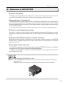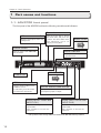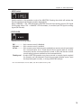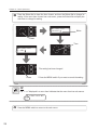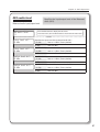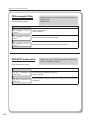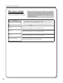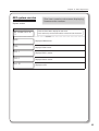
1
User Manual
Notices & Warranties
Copyright Regulations
It is illegal for anyone to violate any of the rights provided by the copyright laws to the owner of
copyright, except for fair use (mainly private noncommercial use). Also, in certain cases copying
is prohibited with no exceptions. In no event shall Grass Valley be liable for any direct or indirect
damages whatsoever arising from the use of captured materials.
Warranty
Your ADVC700 options are covered by a limited warranty when you register your Grass Valley
product. This warranty is for a period of one year (or two years in European Union countries) from the
date of purchase from Grass Valley or an authorized Grass Valley agent. This warranty applies only
to the original purchaser of the Grass Valley product and is not transferable, Grass Valley warrants
that for this period the product will be in good working order. Should our product fail to be in good
working order, Grass Valley will, at its option, repair or replace it at no additional charge, provided
that the product has not been subjected to misuse, abuse or non-Grass Valley authorized alternations,
modifications and/or repair. Proof of purchase is required to validate your warranty.
Grass Valley is not responsible for any lost profits, lost savings or other incidental or consequential
damages arising out of the use of, or inability to use, this product. This includes damage to property
and, to the extent permitted by law, damages for personal injury. This warranty is in lieu of all other
warranties of merchantability and fitness for a particular purpose.
Cautions
Please observe the following cautions when using this product. If you have any questions regarding
the method of usage, the descriptions herein, or any other concerns, please contact Grass Valley
Technical Support.
DANGER
The following conditions indicate the potential for serious bodily injury or loss of life.
Health precautions
In rare cases, flashing lights or stimulation from the bright light of a computer display or TV monitor
may trigger temporary epileptic seizures or loss of consciousness. It is believed that even individuals
whom have never experienced such symptoms may be susceptible. If you or close relatives have
experienced any of these symptoms, consult a doctor before using this product.
Do not use in environments requiring a high degree of reliability and
safety
This product is not to be used in medical devices or life support systems. The characteristics of this
product is not suited for use with such systems.
2
Notices & Warranties
Protect against static electricity
An electrostatic discharge may damage components of this product. Do not directly touch any of the
connectors or component surfaces.
Static electricity can be generated on clothing and on people. Before handling the product, discharge
static electricity from your body by touching a grounded metal surface.
Do not disassemble
Do not remove the cover or modify the Product. Fire, electric shock or malfunction may result. For
internal inspection or repair, please contact your system integrator or Grass Valley directly.
Do not operate at other than the specified voltage
Do not operate at other than the specified voltages of AC 100-240V. Operation at other than the rated
voltage may result in fire or malfunction.
Do not operate with other than the specified power supply
Do not operate with other than the specified AC adapter, or with a car power supply. Such operation
may result in fire or malfunction.
Handle the AC adapter cord carefully
Do not place heavy objects on top of the cord, or place it near hot objects. Doing so may damage the
cord and result in fire, electrical shock, or malfunction. Altering the cord, or excessively bending or
pulling the cord may result in fire or electrical shock. If the cord is damaged, please contact your local
retail outlet or Grass Valley directly.
CAUTION
The following conditions indicate the potential for bodily harm, damage to hardware or loss of data.
Do not pull AC adapter cord when disconnecting from electrical outlet
When disconnecting the AC adapter cord, pull on the plug, not the cord itself. Pulling on the cord can
damage the cord and may result in fire or electric shock.
Do not touch AC adapter with wet hands
Do not disconnect or plug in the AC adapter when your hands are wet. Contact with water may result
in electric shock, fire or damage.
Do not setup in areas subject to heat
Do not setup in an area exposed to direct sunlight or near a heating apparatus. The heat can
accumulate, causing burns, fire or damage. Also, the unit may become deformed or change color.
Only setup using the prescribed method
Do not setup in a manner other than prescribed. Do not use while wrapped in cloth or plastic. Heat
can accumulate, causing burns, fire or damage.
3
Notices & Warranties
If product will not be used for an extended period
If this product will not be used for an extended period of time, disconnect the AC adapter from the
electrical outlet.
Do not cover the ADVC700 ventilation
Do not use the ADVC700 covered with a cloth or in an ill-ventilated room.
Covering the vent may cause heat inside of the product resulting in fire or product malfunction.
Precautions for use of AC adapter
The supplied AC adapter and power cord are for exclusive use of this product. Do not operate the
product with other AC adapter or in other combinations.
FCC Notice
This equipment has been tested and found to comply with the limits for a Class A digital device,
pursuant to Part 15 of the FCC Rules. These limits are designed to provide reasonable protection
against harmful interference when the equipment is operated in a commercial environment. This
equipment generates, uses, and can radiate radio frequency energy and, if not installed and used in
accordance with the instruction manual, may cause harmful interference to radio communications.
Operation of this equipment in a residential area is likely to cause harmful interference in which case
the user will be required to correct the interference at his own expense.
CE Notice
WARNING
This is a class A product. In a domestic environment this product may cause radio interference in
which case the user may be required to take adequate measures.
Declaration of Conformity
According to FCC Part 15
Responsible party Name:
Canopus Corporation
Address:
711 Charcot Avenue, San Jose, CA 95131
Telephone:
408-954-4500
Declares that product Model: ADVC-700
complies with Part 15 of the FCC Rules.
4
Notices & Warranties
Product Notes
1. Unauthorized copying of a portion or the entirety of this product is prohibited.
2. The description and specifications of this product are subject to future change without notice.
3. The description of this product has been prepared to be as complete as possible.
If the reader is aware of any questionable points, errors or omissions, please contact Grass
Valley.
4. The company assumes no liability for the results of practical application, regardless of item (3)
above.
5. Regardless of whether negligence occurs during usage, the company assumes no liability, even
if there is a claim for extraordinary, incidental or derivative loss, including the loss of profits, that
arises during practical application of this product.
6. The analysis, reverse engineering, recompiling and disassembling of the software, hardware or
manuals that accompany this product, and all other related products including miscellaneous
supplemental items, are prohibited.
7. Canopus, as written in both English and Japanese, and its logo are registered trademarks of
Canopus Co., Ltd.
8. ADVC is registered trademark of Canopus Co., Ltd.
9. Microsoft and Windows are registered trademarks of Microsoft Corporation in the US and other
countries.
10. Macintosh is registered trademark of Apple Computer, Inc.
11. Other product names and related items are trademarks or registered trademarks of their respective
companies.
5
Notices & Warranties
About the Documentation
This document is the ADVC700 User Manual.
Information not listed in this document may be listed elsewhere.
In cases where there is a difference between a description in this document and an actual operation
method, the actual operation method takes precedence.
6
Table of Contents
Table of Contents
Table of Contents
Copyright Regulations ........................................................................................................... 2
Warranty ................................................................................................................................. 2
Cautions .................................................................................................................................. 2
FCC Notice .............................................................................................................................. 4
CE Notice ................................................................................................................................ 4
Declaration of Conformity ..................................................................................................... 4
Product Notes......................................................................................................................... 5
About the Documentation ..................................................................................................... 6
About This Manual ................................................................................................................. 6
Table of Contents ................................................................................................................... 7
Chapter 1 - Introduction
1 Introduction ...................................................................... 10
1-1. Package contents ........................................................................................................... 10
1-2. Customer Support ......................................................................................................... 10
1-3. web-site .......................................................................................................................... 10
1-4. Online user registration ................................................................................................. 10
1-5. Limitations ...................................................................................................................... 10
2 Features of ADVC700 ........................................................ 11
Chapter 2 - Basic Operations
1 Part names and functions ................................................. 14
1-1. ADVC700 front panel ..................................................................................................... 14
1-2. ADVC700 rear panel ...................................................................................................... 16
1-3. DIP switch settings ......................................................................................................... 18
1-4. LCD screen displays ...................................................................................................... 19
2 Connecting devices ........................................................... 23
2-1. Connecting ADVC700 unit ............................................................................................. 23
2-2. Importing analog data to your PC ................................................................................. 25
2-3. Recording PC-edited data onto a tape with VCR .......................................................... 26
3 Setting menu ..................................................................... 27
3-1. Menu operations ............................................................................................................ 27
3-2. Setting parameters ........................................................................................................ 29
Chapter 3 - Appendix
1 Specifications .................................................................... 52
8
Chapter 1
Introduction
This chapter explains about the things to
know prior to setting up the ADVC700. Before
you start using ADVC700, read this chapter to
ensure that you have a trouble-free setup.
- Introduction
- Features of ADVC700
Chapter 1 - Introduction
1 Introduction
1-1. Package contents
Please verify that the following items are included in the ADVC700 package. If any of the
components are missing, please contact Grass Valley Customer Support.
• 1 x ADVC700 unit
• 1 x AC adaptor & cable
• 1 x DV cable [6 pin - 4 pin]
• 2 x Rack-mount brackets
• 4 x Attachment screws
• 1 x ADVC700 User Manual (This document)
1-2. Customer Support
For questions regarding hardware setup and usage, please contact your local Grass Valley office,
distributor or the store where you have purchased this product.
1-3. web-site
Including ADVC700, the latest company information is announced at our website
http://www.canopus.com/. The latest drivers, utilities, product manuals, FAQs, etc. are also
available at our website.
1-4. Online user registration
You can register your ADVC700 at the Canopus website.
http://www.canopus.com/support/supportcenter.php
1-5. Limitations
• Limitations on the nonstandard signal
While the ADVC700 can convert the signals output by game consoles, there is a possibility that
some software will be unable to synchronize some video and audio signals.
* In order to capture the nonstandard signal, such as one from a game console without audio noise, enable the
“108 DV-out frame sync.” In this instance, frame-skip or frame-hold will occur.
• Limitations on the ADVC700 connection
Before you connect(disconnect) your ADVC700 to(from) a PC, ensure that the PC has been
powered off.
• Limitations on connecting your ADVC700 to Windows 2000 PC through IEEE1394
interface (OHCI)
When your ADVC700 is operating in NTSC, the DV frame rate being output from the OHCI
driver is markedly slower than the standard frame rate. Therefore, glitches in both the frame
hold and time-code can occur regularly while the DV output signal is being converted to an
analog signal. This phenomenon does not occur, however, when the signal is input through
OHCI from the ADVC700.
10
Chapter 1 - Introduction
2 Features of ADVC700
• Pursuit of video quality
The highly acclaimed Canopus DV Codec functions as the DV Codec chip and performs the
core work for analog/DV conversion. This allows for high quality video conversion.
• High synchronism: “Locked Audio”
The ADVC700 uses a locked audio function to digitize the audio signal by synchronizing it
precisely with the speed of the video signal. When the audio and video data are synchronized,
the analog audio input will not get out of sync with the video. Lengthy content, such as a movie,
can be converted easily.
* The locked audio function only works in analog DV conversion. It will not function in a DV-DV connection.
• Perfect Sync technology(patent pending)
During DV analog conversion, Perfect Sync technology (patent pending) facilitates conversion
and results in precise synchronization with the REF input signal, also eliminating any skip
holds.
• Professional specifications adapt to a variety of studio uses
Designed for quick and easy introduction to a wide range of studio systems, the ADVC700
features AV/C RS422 conversion-driven VCR control and a full complement of reference
inputs and LTC I/O.
• EIA-compliant 19-inch rack-mount
The ADVC700, a stand-alone unit with a generic format, the IEEE1394 interface, can handily be
connected to any PC without the need for additional hardware.
In addition, the ADVC700, as a 19-inch unit, the EIA standard, can be mounted to a director’s
rack together with a VCR.
TIP
When mounting the ADVC700 on a rack:
1. Use a Phillips-head screwdriver to remove the four rubber legs from the bottom of
the unit; and
2. Attach the rack-mount bracket to the ADVC700 unit with the screws provided.
11
Chapter 1 - Introduction
• Simple user-friendly menu settings
The ADVC700 settings can be altered by using the select dial and the buttons on the front
panel. The current setting will display on the LCD.
The ADVC700 will also save its most recently used settings when the unit power is turned
off, and those settings will automatically restore when the unit is turned back on. (All settings
changed with the front panel switches will be recovered.)
• Save/Restore user settings
You can save/restore up to three different settings, enabling the user to choose from the most
appropriate settings from past usage.
• Versatility with all PCs
The ADVC700 utilizes a DV format; therefore its usability is not limited by either Windows or
Macintosh. The input/output functions of component video, composite video, S-video, audio
XLR and audio RCA can all be employed by simple connection to the IEEE1394 interface,
without any need to change the current environment.
• Versatility in NTSC/PAL
As well as NTSC, which is the format used in Japan and US, PAL format, which is more common
in European and other countries, can also be selected.
* NTSC-PAL (SECAM) conversion cannot be done with the ADVC700.
* Even once the ADVC700 has been mounted to a director’s rack, video settings can still be easily changed by
accessing the front panel settings.
12
Chapter 2
Basic Operations
This chapter explains the basics of the ADVC700,
such as part names, functions, etc.
- Part names and functions
- Connecting devices
- Setting menu
- Specifications
Chapter 2 - Basic Operations
1 Part names and functions
1-1. ADVC700 front panel
The front panel of the ADVC700 unit has the following controllers and indicators.
Select dial
LCD
Displays input/output status and
setting menu
Turn the Select dial to choose
the menu items, and press it to
confirm. The menus which don't
have sub-menus, can be set
only by choosing them.
MODE switch
P15
POWER switch
MODE indicator
Turns the power of the ADVC-700
unit on and off.
Displays the currently selected
operation mode.
STATUS LED
POWER LED
P15
MENU switch
Switches between Main screen
and Menu screen.
In sub-menu, press this switch
to return to the main menu.
DIGITAL AUDIO PEAK METER
Displays the peak level of the audio that is
currently being input or output.
AUDIO INOUT LEVEL dial
(INPUT-CH1)
Adjusts the analog audio level
input to CH1.
Turn clockwise to increase the
input level.
AUDIO INOUT LEVEL dial
(INPUT-CH2)
Adjusts the analog audio level
input to CH2.
Turn clockwise to increase the
input level.
* The position of the average audio level is where the dial clicks when you turn it.
14
Chapter 2 - Basic Operations
• MODE switch
Used to switch on the operation mode of the ADVC700. Pressing the switch will activate the
Encode operation and Decode operation alternatively.
When “ANALOG DV” LED illuminates, ADVC700 converts input analog signal to DV signal
(DV Encode). When “DV ANALOG” LED illuminates, it converts input DV signal to analog
signal (DV Decode).
•STATUS LED
Displays the following status.
Off:.................... 9-pin remote control is disabled.
Lit green: .......... 9-pin remote control is enabled.
Lit red: .............. 9-pin remote control has been set to enabled, but remote control is prevented
by a communication error. Check that the 9-pin remote cable is correctly
connected, that the connected device’s power is ON, and that the remote
control setting has been enabled on the connected device.
Flashing red:.... A major ADVC700 operation error has occurred, or several signals required
for operation can’t be detected. Check the error status display screen. Input
the required signals correctly, or change ADVC700’ settings.
* For more information on error status, see “Error status screen“ (p.22).
15
Chapter 2 - Basic Operations
1-2. ADVC700 rear panel
The rear panel of the ADVC700 has the following connectors.
ANALOG AUDIO IN
(Balanced input)
Input connectors for balanced
audio signal. The left connector
on the rear panel is CH1, and the
right one is CH2.
COMPONENT VIDEO
ANALOG AUDIO IN
(Unbalanced input)
LOCKED
Input connectors for unbalanced
audio signal. The connector on
the upper row is CH1, and one
on the lower row is CH2.
Input and output connectors for
component video signal. The
three connectors on the upper
row are video input, and the
three connectors on the lower
row are video output.
ANALOG AUDIO OUT
(Balanced output)
Output connectors for balanced
audio signal. The left connector
on the rear panel is CH1, and the
right one is CH2.
16
DV1
ANALOG AUDIO OUT
(Unbalanced output)
Output connectors for unbalanced
audio signal. The connector on
the upper row is CH1, and one on
the lower row is CH2.
DV2
Chapter 2 - Basic Operations
Earth terminal
COMPOSITE
Connect an earth wire to this terminal, if necessary.
Input and output connectors for composite
video signal. The connector on the upper
row is composite input, and the connector
on the lower row is composite output.
Remote
Remote control connector.
TC
S-Video
LOCKED
Input and output connectors for
S-Video signal. The connector
on the upper row is video input,
and the connector on the lower
row is video output.
Time-code I/O connectors. The
connector on the upper row is
TC input, and one on the lower
row is TC output.
DV1
DV2
DIP SW
DV1 (6-pin)
P18
REF
Input connectors receiving sync
signal. The LED lights red when
sync signal input is detected. The
REF connector has through output.
If a cable is not connected to the
output connector, it has a 75
automatic termination.
Use a DV cable to connect the ADVC700
to a DV device or a PC. (Bus power is not
supplied.)
DV2 (4-pin)
Use a DV cable to connect the ADVC700
to a DV device or a PC.
DC-IN 12V
Connect the provided AC
adapter here.
NOTES
- This unit will not work as an OHCI Hub with Grass Valley DV products.
- To use this unit as a Hub with OHCI devices, the application also needs to support
two or more devices.
17
Chapter 2 - Basic Operations
1-3. DIP switch settings
The rear panel of the ADVC700 unit has the following DIP switches. Default SW3, SW4 settings
may differ depending on the place of purchase.
PHY SPEED
S400
S200
Update Mode
Normal
Update
Video Format
NTSC
PAL
PAL/SECAM
PAL
SECAM
0 IRE
7.5 IRE
(When SW3 is set to ON)
NTSC Setup Level
(When SW3 is set to OFF)
• SW1: PHY Speed
Designates the PHY speed.
OFF: S400
ON: S200
• SW2: Update Mode
Used to update the internal software.
(Set this switch to the OFF position for normal operations.)
OFF: Normal
ON: Update
• SW3: Video Format
Designates the video signal format.
* Enabled only when the setting in the menu option “107 video standard” is “set by DIP switch”.
OFF: NTSC
ON: PAL
• SW4: PAL/SECAM (When SW3 is set to ON)
* Enabled only when the setting in the menu option “107 video standard” is “set by DIP switch”.
OFF: PAL
ON: SECAM
: NTSC Setup Level (When SW3 is set to OFF)
* Enabled only when the setting in the menu option “107 video standard” is “set by DIP switch”.
OFF: 0 IRE
ON: 7.5 IRE
CAUTION
Make sure to turn off the power of ADVC700 unit before making any changes for DIP
switch settings.
18
Chapter 2 - Basic Operations
1-4. LCD screen displays
ADVC700 has two main screens and an error status screen. Turn the Select dial to switch between
the main screens and the error status screen. Pressing the MENU button displays the setting
menu screen.
Main screen 1
This screen shows the current status of the operation.
• ANALOG DV mode
1. Video input
2. Audio format
Displays the video source.
Displays the audio status.
S VIDEO 48k BAL.
PLAY
00:00:00;00
3. 9-pin remote control deck status
4. Input time code
Displays the status of the remote control deck.
Displays the time code.
1. Video input
COMPONENT .............Signal from the component connector is input.
S VIDEO .....................Signal from the S-Video connector is input.
COMPOSITE ...............Signal from the composite connector is input.
2. Audio format
48k BAL. .....................Converts the input Balanced audio signal to 48kHz, 16 bit audio.
48k UNBAL. ................Converts the input Unbalanced audio signal to 48kHz, 16 bit audio.
32k BAL. .....................Converts the input Balanced audio signal to 32kHz, 12 bit audio.
32k UNBAL. ................Converts the input Unbalanced audio signal to 32kHz, 12 bit audio.
3. 9-pin remote control deck status
If blank ........................9-pin remote control is not in use.
NoDevice....................Can’t find deck. Check cable connection.
NoCASETTE ...............No tape in deck.
STOP ..........................Deck is stopped.
PLAY ...........................Deck is playing.
STILL ..........................Deck is paused.
F.FWD .........................Deck is fast-forwarding.
REW ............................Deck is rewinding.
REC .............................Deck is recording.
SHUTTLE ....................Deck is shuttling.
19
Chapter 2 - Basic Operations
4. Input time code
00:00:03:22 ................For PAL/NTSC NDF (Non Drop Frame)
* A colon is used between seconds and frames as a delimiter.
00:00:03;22 ................For NTSC DF (Drop Frame)
* A semicolon is used between seconds and frames as a delimiter.
--:--:--:-- ......................No DV signal output
* Free-run time code is used during built-in color bar output or when time code is
not input.
• DV ANALOG mode
1. Video input
2. Audio format
Displays the video source.
Displays the audio status.
DVCAM
PLAY
32k
00:00:00;00
3. 9-pin remote control deck status
4. Input time code
Displays the status of the remote control deck.
Displays the time code.
1. Video input
DVCAM ......................DVCAM signal is input.
DV ...............................DV signal is input.
----- ..............................No DV signal detected.
2. Audio format
48k ..............................The DV audio signal input is 48kHz, 16 bit.
44k ..............................The DV audio signal input is 44.1kHz, 16 bit.
32k ..............................The DV audio signal input is 32kHz, 16 or 12 bit.
----- ..............................No DV signal detected.
3. 9-pin remote control deck status
If blank ........................9-pin remote control is not in use.
NoDevice....................Can’t find deck. Check cable connection.
NoCASETTE ...............No tape in deck.
STOP ..........................Deck is stopped.
PLAY ...........................Deck is playing.
STILL ..........................Deck is paused.
F.FWD .........................Deck is fast-forwarding.
REW ............................Deck is rewinding.
REC .............................Deck is recording.
SHUTTLE ....................Deck is shuttling.
20
Chapter 2 - Basic Operations
4. Input time code
00:00:03:22 ................For PAL/NTSC NDF (Non Drop Frame)
* A colon is used between seconds and frames as a delimiter.
00:00:03;22 ................For NTSC DF (Drop Frame)
* A semicolon is used between seconds and frames as a delimiter.
--:--:--:-- ......................No DV signal input
* Free-run time code is used during built-in color bar output or when time code is
not input.
Main Screen 2
This screen shows the information on the current settings.
1. External synchronization enabled/disabled
Displays the current setting of the external synchronization.
GENLOCK:enable
REMOTE:enable NTSC
2. 9-pin remote enabled/disabled
Displays the current setting of the 9-pin remote.
3. Video standard
Displays the current video standard.
1. External synchronization enabled/disabled
disable ........................External synchronization function is disabled.
enable .........................External synchronization function is enabled.
advanced....................External synchronization function in the “perfect sync mode” is
enabled.
2. 9-pin remote enabled/disabled
disable ........................9-pin remote control function is disabled.
enable .........................9-pin remote control function is enabled.
3.Video standard
NTSC ..........................ADVC700 operates in NTSC mode.
PAL .............................ADVC700 operates in PAL mode.
SECAM .......................ADVC700 operates in SECAM mode.
21
Chapter 2 - Basic Operations
Error status screen
This screen shows error messages.
• Error is not detected
No Error
• When error has occurred (When status LED is lit red)
not detected:
VIDEOin REFin
VIDEOin ......................Analog input signal specified by “001 video input“ can’t be detected
during Analog DV mode. If “104 DVout auto-mute” is set to off, error
will not occur even when no analog input signal can’t be detected.
* When “601 SG output” is set to ON, this message will not be displayed.
REFin ..........................Sync signal from the REF input connector can’t be locked, while
“401 ext. sync” is set to “enable” or “advanced” during Analog DV
mode.
* When “601 SG output” is set to ON, this message will not be displayed.
22
Chapter 2 - Basic Operations
2 Connecting devices
2-1. Connecting ADVC700 unit
Connect the ADVC700 unit to your system. The diagram below illustrates the typical connection
of the ADVC700.
• Standard (Connection to a VCR with component connectors and a PC)
VCR
AUDIO OUT
REMOTE connector
AUDIO IN
LOCKED
COMPONENT video
connection connector
DV1
DV2
IEEE 1394 connector
S-video connector
Speaker
Monitor
Display
PC
NOTES
DV editing software is required to playback or capture video files for use on a PC or
to record the file data onto tape. In addition, the PC should be equipped with an IEEE1394 connector.
CAUTION
When connecting a PC to the ADVC700 unit, make sure that the PC’s power is turned
off.
23
Chapter 2 - Basic Operations
• System integrated
VCR
Sync signal generator
Sync signal
LOCKED
Video switcher
DV1
DV2
Speaker
Monitor
Display
PC
NOTES
DV editing software is required to playback or capture video files for use on a PC or
to record the file data onto tape. In addition, the PC should be equipped with an IEEE1394 connector.
CAUTION
When connecting a PC to the ADVC700 unit, make sure that the PC’s power is turned
off.
24
Chapter 2 - Basic Operations
2-2. Importing analog data to your PC
Import the material of the tape on VCR into a PC.
PC
(IEEE 1394 connector)
Digital
Display
ADVC700
Analog
VCR
Analog
Analog
When entering the data
via DV editing software
Speaker
Monitor
1
Press the [Mode] switch on the front panel of the ADVC700 to switch the mode to the
[ANALOG DV].
Press
2
Light
Capture the data by using DV editing software.
* For the operational procedure of the DV editing software, refer to the instruction manual provided with
your DV editing software.
25
Chapter 2 - Basic Operations
2-3. Recording PC-edited data onto a tape with VCR
Output the DV data from a PC and record it with a VCR.
PC
(IEEE 1394 connector)
Digital
Display
ADVC700
Analog
VCR
Analog
When outputting via
the DV editing software
Analog
Speaker
Monitor
1
Press the [Mode] switch on the front panel of the ADVC700 to switch the mode to the
[DV ANALOG].
Press
2
Light
Use the DV editing software to output your data.
* For the operational procedure of the DV editing software, refer to the instruction manual provided with
your DV editing software.
3
26
Use the VCR to record the data on tape.
Chapter 2 - Basic Operations
3 Setting menu
3-1. Menu operations
1
Press the Select dial, or MENU switch to go to the setting menu screen.
001 video input
component
Setting menu is displayed on LCD
Press
2
Turn the Select dial to choose the menu item to set.
101 video input adj.
>>>
Turn
Choose the menu item
Turn the Select dial clockwise to proceed the setting menus.
Turn
001 video input
component
002 audio input
balanced
101 video input adj.
>>>
Turn the Select dial counterclockwise to go back the setting menus.
Turn
001 video input
component
002 audio input
balanced
101 video input adj.
>>>
27
Chapter 2 - Basic Operations
3
Press the Select dial to have the item chosen, and turn the Select dial to change its
setting. If the menu item chosen has a sub-menu, press the Select dial to display the
sub-menu to change its setting.
001 video input
component
Blinks
Press
Turn
001 video input
S video
The setting has been changed
Press
* Press the MENU switch if you want to cancel the setting.
TIP
The “>>>“displayed in a menu item indicates that the menu item has sub-menus.
101 video input adj.
>>>
4
28
Press the MENU switch to return to the main menu.
Chapter 2 - Basic Operations
3-2. Setting parameters
000 - 099 Analog AV input settings
Analog video input setting ------------------------------------------- 001 video input ------------
31
Analog audio input setting ------------------------------------------- 002 audio input -----------
31
100 - 199 Video input/output settings
Video input adjustment settings ----------------------------------- 101 video input adj. -------
32
Video output adjustment settings --------------------------------- 102 video output adj -----
35
Video output auto-off settings -------------------------------------- 103 Vout auto-off ---------
36
DV output auto-off setting ------------------------------------------- 104 DVout auto-mute ----
36
DV output aspect ratio settings ------------------------------------- 105 DV aspect info -------
37
S-Video output aspect ratio setting ------------------------------- 106 Sout aspect info-----
38
Video standard settings ----------------------------------------------- 107 video standard -------
38
DV out frame synchronizer setting -------------------------------- 108 DVout frame sync ---
39
200 - 299 Audio input/output settings
DV audio encode setting --------------------------------------------- 201 DV audio encode -----
39
Balanced audio headroom (Reference level) ------------------- 202 audio headroom ------
40
Balanced audio input/output level --------------------------------- 203 audio level ------------
41
400 - 499 External synchronization settings
External synchronization --------------------------------------------- 401 ext. sync --------------
42
External synchronization configuration -------------------------- 402 ext. sync conf. -------
42
Audio out delay setting ----------------------------------------------- 403 audio out delay -------
43
500 - 599 9-pin remote control settings
9-pin remote control setting ----------------------------------------- 501 9P remote ------------
43
29
Chapter 2 - Basic Operations
600 - 699 Signal generator output settings
Color bar output --------------------------------------------------------- 601 SG output ------------
43
SG audio level ----------------------------------------------------------- 602 SG audio level --------
44
700 - 799 Other detailed settings
IEEE1394 clock adjustment ------------------------------------------ 701 1394 clock adj. ------
44
Local switch disable---------------------------------------------------- 702 local disable ----------
45
Cycle master enable/disable----------------------------------------- 703 cycle master ---------
45
Resample filter setting------------------------------------------------- 704 resample filter -------
46
AV/C transaction setting ---------------------------------------------- 705 AV/C transaction ----
46
Maximum data rate ---------------------------------------------------- 706 data rate cap. -------
47
900 - 999 System settings
30
Save settings ------------------------------------------------------------- 901 save settings --------
47
Restore settings (Default settings) --------------------------------- 902 restore settings ----
48
System version ---------------------------------------------------------- 903 system version ------
49
Chapter 2 - Basic Operations
001 video input
Specifies the input video source to be used in
Analog DV mode (DV encoding).
Analog video input setting
LCD display
001 video input
component
Inputs signal from the Component connectors.
(Factory default)
001 video input
S video
Inputs signal from the S-Video connector.
001 video input
composite
Inputs signal from the Composite connector.
002 audio input
Specifies the input audio source to be used in
Analog DV mode (DV encoding).
Analog audio input setting
LCD display
002 audio input
balanced
Inputs signal from the Balanced audio connectors.
(Factory default)
002 audio input
unbalanced
Inputs signal from the Unbalanced audio connectors.
31
Chapter 2 - Basic Operations
101 video input adj.
Adjusts the video quality of the input video.
Video input adjustment settings
* According to "001 video input" settings, some menu items may not be available.
LCD display
101 video input adj.
>>>
Press the Select dial to display the sub-menu.
In the sub-menu, turn the Select dial to choose the sub-menu item.
sub-menu
brightness
512
Adjusts brightness of image. The smaller the value is, the darker the
image is; the larger, the brighter.
Set specified numerical value between 0 and 1023.
(Factory default: 512)
contrast
128
Adjusts contrast of image. The smaller the value is, the weaker the
contrast is; the larger, the stronger.
Set specified numerical value between 0 and 255.
(Factory default: 128)
hue
Adjusts hue of image. Taking yellow as an example, the smaller the
value is, the closer to red; the larger, the closer to green.
Set specified numerical value between 0 and 255.
(Factory default: 128)
128
32
saturation
128
Adjusts color strength. The smaller the value is, the lighter the color
is; the larger, the darker. You can reproduce complete gray-scale
with minimum value 0 (zero).
Set specified numerical value between 0 and 255.
(Factory default: For composite/S video)
NTSC 0 IRE: 128 7.5 IRE: 138 PAL: 128 SECAM: 128
(Factory default: For component)
NTSC Betacam 0 IRE: 148 7.5 IRE: 160
PAL: 213 SECAM: 213
sharpness
128
Adjusts sharpness of image outline. The smaller the value is, the
more blur image outline is; the larger, the sharper.
Set specified numerical value between 0 and 255.
(Factory default: 128)
component level
Betacam
Specifies the component level (NTSC/component only)
Betacam
Sets Betacam (Factory default)
SMPTE
Sets SMPTE.
Chapter 2 - Basic Operations
3D visual processing
none
2D luma NR
none
2D chroma NR
none
black gain
none
B adaptation level
level 1
Set the effects for 3D noise reduction and 3D video processing.
(NTSC only) (Available only to Composite or S-video)
none
Disables the 3D noise reduction.
(Factory default)
3D Y/C
Enables 3D Y/C (composite only)
3D NR(low)
Enables low 3D noise reduction filter.
3D NR(middle)
Enables medium 3D noise reduction filter.
3D NR(high)
Enables high 3D noise reduction filter.
Eliminates the noise on the luminance component by non-linear
noise extract filter.
none
Disables the 2D luminance noise extract.
(Factory default)
low
Enables low 2D noise extract filter.
middle
Enables medium 2D noise extract filter.
high
Enables high 2D noise extract filter.
Eliminates the noise on the color component by non-linear noise
extract filter.
none
Disables the 2D chrominance noise extract.
(Factory default)
low
Enables low 2D noise extract filter.
middle
Enables medium 2D noise extract filter.
high
Enables high 2D noise extract filter.
Strengthens the gain in low luminance area toward luminance
signal. As the setting becomes stronger, black gain becomes more
emphasized.
When set to [none], the "B adaptation level", "black threshold" settings
will be invalid.
none
Disables the black gain. (Factory default)
low
Enables low black gain filter.
middle
Enables medium black gain filter.
high
Enables high black gain filter.
Sets the adjustment volume for black expansion. As the adjustment
volume is larger, black gain becomes more emphasized.
level 1
level 2
black threshold
0
(Factory default)
4
Specifies the luminance level to enhance black element. The higher
the value the more bright the luminance level will be.
Set specified numerical value between 0 and 255.
(Factory default: 0)
33
Chapter 2 - Basic Operations
white gain
none
W adaptation level
level 1
Strengthens the gain in high luminance area toward luminance signal.
This option improves the gradation reproducibility for damaged area
seen as white due to high luminance.
When set to [none], the "W adaptation level", "white threshold" settings
will be invalid.
none
Disables the white gain. (Factory default)
low
Enables low white gain filter.
middle
Enables medium white gain filter.
high
Enables high white gain filter.
Sets the adjustment volume for white gain limit. As the limit volume is
larger, white gain will be adjusted to lower.
level 1
level 2
white threshold
255
Sets to which level of luminance (brightness) white gain will be
adjusted lower. The level will be set darker as you set a larger value.
(Factory default: 255)
H outline enhance
none
Sets the outline adjustment for horizontal direction (edge of vertical line).
V outline enhance
none
34
(Factory default)
4
none
Disables horizontal outline enhance.
(Factory default)
low
Enables low horizontal outline enhance.
middle
Enables medium horizontal outline enhance.
high
Enables high horizontal outline enhance.
Sets the outline adjustment for vertical direction (edge of horizontal line).
none
Disables vertical outline enhance.
(Factory default)
low
Enables low vertical outline enhance.
middle
Enables medium vertical outline enhance.
high
Enables high vertical outline enhance.
Chapter 2 - Basic Operations
102 video output adj
Adjusts settings on output video.
Video output adjustment settings
LCD display
102 video output adj
>>>
Press the Select dial to display the sub-menu.
In the sub-menu, turn the Select dial to choose the sub-menu item.
sub-menu
component level
Betacam
Specifies the component level (NTSC only).
Betacam
Specifies the component level to Betacam.
(Factory default)
SMPTE
Specifies the component level to SMPTE.
composite/S gain
0
Adjusts the composite/S gain.
Set specified numerical value between -32 and 32.
(Factory default: 0)
component gain
0
Adjusts the component gain.
Set specified numerical value between -32 and 32.
(Factory default: 0)
35
Chapter 2 - Basic Operations
103 Vout auto-off
Specifies the output connector that automatically
stops the video output in ANALOG DV mode
(DV encoding).
When the external sync signal is not used, set
this option to [auto-off] to prevent a looped
connection with a connected device.
Video output auto-off settings
LCD display
103 Vout auto-off
>>>
Press the Select dial to display the sub-menu.
In the sub-menu, turn the Select dial to choose the sub-menu item.
sub-menu
composite
output
Specifies the composite output setting.
output
Does not stop outputting video signal.
(Factory default)
auto-off
Stops outputting video signal.
Specifies the S-Video output setting.
S video
output
component
output
output
Does not stop outputting video signal.
(Factory default)
auto-off
Stops outputting video signal.
Specifies the component output setting.
output
Does not stop outputting video signal.
(Factory default)
auto-off
Stops outputting video signal.
104 DVout auto-mute
DV output auto-off setting
Select the conditions where ADVC700
automatically stops the DV output in ANALOG DV mode (DV encoding).
LCD display
36
104 DVout auto-mute
off
Does not stop DV stream.
104 DVout auto-mute
no video signal
Stops DV stream automatically. When video is not input.
(Factory default)
Chapter 2 - Basic Operations
105 DV aspect info
DV output aspect ratio settings
Specifies the aspect ratio for the DV stream that
ADVC700 outputs in ANALOG DV mode (DV
encoding).
LCD display
For NTSC
105 DV aspect info
4:3
Sets the DV stream in 4:3 aspect ratio.
(Factory default)
105 DV aspect info
16:9(letter box)
Sets the DV stream in 16:9 aspect ratio (letter box).
105 DV aspect info
16:9(squeeze)
Sets the DV stream in 16:9 aspect ratio (squeeze).
For PAL/SECAM
105 DV aspect info
4:3
Sets the DV stream in 4:3 aspect ratio.
(Factory default)
105 DV aspect info
16:9(letter box)
Sets the DV stream in 16:9 aspect ratio (letter box).
105 DV aspect info
16:9(anamorphic)
Sets the DV stream in 16:9 aspect ratio (anamorphic).
37
Chapter 2 - Basic Operations
106 Sout aspect info
Specifies the aspect ratio for the S-Video that
ADVC700 outputs.
S-Video output aspect ratio setting
LCD display
106 Sout aspect info
4:3
Sets the S-Video in 4:3 aspect ratio.
(Factory default)
106 Sout aspect info
16:9(letter box)
Sets the S-Video in 16:9 aspect ratio (letter box).
106 Sout aspect info
16:9
Sets the S-Video in 16:9 aspect ratio.
107 video standard
Specifies the video standard. Once you have
changed the video standard settings (or the setup
level), you are prompted to turn the power off to
make the new setting take effect.
Video standard settings
LCD display
107 video standard
>>>
Press the Select dial to display the sub-menu.
In the sub-menu, turn the Select dial to choose the sub-menu item.
sub-menu
video standard
NTSC(525)/0IRE
38
Specifies the video standard.
NTSC(525)/
0IRE
Sets to NTSC with the setup level of 0 IRE.
NTSC(525)/
7.5IRE
Sets to NTSC with the setup level of 7.5 IRE.
PAL(625)
Sets to PAL.
SECAM(625)
Sets to SECAM.
set by DIP
switch
Adopts the setting by the DIP switch on the rear
panel. (Factory default)
Chapter 2 - Basic Operations
108 DVout frame sync
Enables/Disables the frame synchronizer on the
output DV stream.
DV out frame synchronizer setting
LCD display
108 DVout frame sync
disable
Disables the frame synchronizer.
(Factory default)
108 DVout frame sync
enable
Enables the frame synchronizer.
* Regardless of this setting, the synchronizer takes effect on the output analog video.
* This option is invalid if “501 9P remote” is set to enable.
201 DV audio encode
Specifies the DV audio format in ANALOG DV
mode (DV encoding).
DV audio encode setting
LCD display
201 DV audio encode
48kHz/16bit
Sets to 48kHz, 16bit.
(Factory default)
201 DV audio encode
32kHz/12bit
Sets to 32kHz, 12bit.
39
Chapter 2 - Basic Operations
202 audio headroom
Specifies the input/output headroom of the
Balanced audio (XLR).
Balanced audio headroom
(Reference level)
LCD display
202 audio headroom
>>>
Press the Select dial to display the sub-menu.
In the sub-menu, turn the Select dial to choose the sub-menu item.
sub-menu
in headroom ch 1
16dB
in headroom ch 2
16dB
out headroom ch 1
16dB
out headroom ch 2
16dB
40
Specifies the input headroom of CH 1.
16 dB
Sets to 16dB.
18 dB
Sets to 18dB. (Factory default for PAL/SECAM)
20 dB
Sets to 20dB. (Factory default for NTSC)
Specifies the input headroom of CH 2.
16 dB
Sets to 16dB.
18 dB
Sets to 18dB. (Factory default for PAL/SECAM)
20 dB
Sets to 20dB. (Factory default for NTSC)
Specifies the output headroom of CH 1.
16 dB
Sets to 16dB.
18 dB
Sets to 18dB. (Factory default for PAL/SECAM)
20 dB
Sets to 20dB. (Factory default for NTSC)
Specifies the output headroom of CH 2.
16 dB
Sets to 16dB.
18 dB
Sets to 18dB. (Factory default for PAL/SECAM)
20 dB
Sets to 20dB. (Factory default for NTSC)
Chapter 2 - Basic Operations
203 audio level
Specifies the input/output level of the Balanced
audio (XLR).
Balanced audio input/output level
LCD display
203 audio level
>>>
Press the Select dial to display the sub-menu.
In the sub-menu, turn the Select dial to choose the sub-menu item.
sub-menu
input level ch 1
+4 dBm
input level ch 2
+4 dBm
output level ch 1
+4 dBm
output level ch 2
+4 dBm
Specifies the input level of the balanced audio CH 1.
+4 dBm
Sets to +4 dBm. (Factory default)
0 dBm
Sets to 0 dBm.
Specifies the input level of the balanced audio CH 2.
+4 dBm
Sets to +4 dBm. (Factory default)
0 dBm
Sets to 0 dBm.
Specifies the output level of the balanced audio CH 1.
+4 dBm
Sets to +4 dBm. (Factory default)
0 dBm
Sets to 0 dBm.
Specifies the output level of the balanced audio CH 2.
+4 dBm
Sets to +4 dBm. (Factory default)
0 dBm
Sets to 0 dBm.
41
Chapter 2 - Basic Operations
401 ext. sync
Enables/Disables the external sync operation in
ANALOG DV mode (DV Encoding).
External synchronization
LCD display
401 ext. sync
disable
Disables the external sync operation.
(Factory default)
401 ext. sync
enable
Enables the external sync operation.
401 ext. sync
advanced
Enables the external sync operation as "perfect sync mode".
* This function is only available in DV ANALOG mode (DV decoding). The “advanced” setting is only available
when DV signal is input via an IEEE1394 connector compliant with PC’s OHCI Specification. For supported
operating system for PC, please refer to our web site.
402 ext. sync conf.
External synchronization
configuration
Sets the amount (in unit of 37 nanoseconds) to
increase/decrease the ADVC700 video output
delay (system phase) relative to the external sync
input.
LCD display
402 ext. sync conf.
0
42
Set specified numerical value between -1024 and 1023.
(Factory default: 0)
Chapter 2 - Basic Operations
403 audio out delay
Audio out delay setting
Sets the amount (in unit of milliseconds) to
increase/decrease the ADVC700 audio output
delay relative to the video output, when the
external sync is enabled.
LCD display
403 audio out delay
0 msec
501 9P remote
Set specified numerical value between -100 and 100 msec.
(Factory default: 0)
Enables/Disables the deck control from the 9-pin
remote controller.
9-pin remote control setting
LCD display
501 9P remote
disable
Disables the deck control from the remote connector.
(Factory default)
501 9P remote
enable
Enables the deck control from the remote connector.
601 SG output
Selects the color bar output mode.
Color bar output
LCD display
601 SG output
off
Does not output color bar.
(Factory default)
601 SG output
on
Outputs color bar.
* External synchronization function cannot be used.
Free-run time-code is output.
43
Chapter 2 - Basic Operations
602 SG audio level
Selects the testing audio signal of 1kHz in color
bar output mode.
SG audio level
LCD display
602 SG audio level
-18 dB FS
Sets to -18 dB FS. (Factory default for PAL/SECAM)
602 SG audio level
-20 dB FS
Sets to -20 dB FS. (Factory default for NTSC)
701 1394 clock adj.
Sets the IEEE1394 system clock.
IEEE1394 clock adjustment
LCD display
701 1394 clock adj.
127
44
Normally keep the same setting (127) to the factory default.
(Factory default: 127)
Chapter 2 - Basic Operations
702 local disable
Enables/Disables the MODE switch.
Local switch disable
LCD display
702 local disable
off
Permits operation by the MODE switch.
(Factory default)
702 local disable
on
Prohibits operation by the MODE switch.
702 local disable
auto
Prohibits operation by the MODE switch, only when the deck control
by 9-pin remote connector is enabled.
702 local disable
off(PB mode)
Permits operation by the MODE switch, with the switching by AV/C
command prohibited.
703 cycle master
Cycle master enable/disable
Enables/Disables cycle master acquisition.
If you connect ADVC700/ADVC1000 units each
other using IEEE1394 cable, set this option to
OFF.
LCD display
703 cycle master
off
Does not acquire cycle master.
703 cycle master
on
Acquires cycle master.
(Factory default)
* If this menu is set to Off, external sync of the “perfect sync mode” does not work.
45
Chapter 2 - Basic Operations
704 resample filter
Resample filter setting
Select the type of horizontal resampling filter for
Cb/Cr signal.
(NTSC only)
LCD display
704 resample filter
normal
Sets normal modulus.
(Factory default)
704 resample filter
sharp 1
Sets modulus that emphasizes anti-alias.
704 resample filter
sharp 2
Sets modulus that emphasizes frequency characteristic.
705 AV/C transaction
Select the type of AV/C transaction at the time
AV/C command is received.
AV/C transaction setting
LCD display
46
705 AV/C transaction
immediate
Executes AV/C immediate transaction.
(Factory default)
705 AV/C transaction
deferred
Sends INTERIM response, and then executes AV/C immediate
transaction.
Chapter 2 - Basic Operations
706 data rate cap.
Maximum data rate
Selects the maximum communication speed of
the “dr cap” field of “iMPR/oMPR” at the time of
booting and setting change.
Once you have changed this setting, you are
prompted to turn the power off to make the new
setting take effect.
706 data rate cap.
S100
Sets to S100.
(Factory default)
706 data rate cap.
S200
Sets to S200.
706 data rate cap.
S400
Sets to S400.
901 save settings
Saves the current setting to a user area.
Save settings
LCD display
901 save settings
>>>
Press the Select dial to display the sub-menu.
In the sub-menu, turn the Select dial to choose the sub-menu item.
sub-menu
user 1
Saves the current setting as user 1.
user 2
Saves the current setting as user 2.
user 3
Saves the current setting as user 3.
47
Chapter 2 - Basic Operations
902 restore settings
Restore settings (Default settings)
Restores the user setting, or to the factory default.
Once you have changed this setting, you may be
prompted to turn the power off to make the new
setting take effect.
LCD display
902 restore settings
>>>
Press the Select dial to display the sub-menu.
In the sub-menu, turn the Select dial to choose the sub-menu item.
sub-menu
48
user 1
Restores the settings to the ones saved as user 1.
user 2
Restores the settings to the ones saved as user 2.
user 3
Restores the settings to the ones saved as user 3.
factory default
Restores the settings to the factory default.
Chapter 2 - Basic Operations
903 system version
This item contains sub-menus displaying
firmware version numbers.
System version
LCD display
903 system version
>>>
Press the Select dial to display the sub-menu.
In the sub-menu, turn the Select dial to choose the sub-menu item.
sub-menu
uCOM
Displays uCOM version.
FPGA
Displays FPGA version.
CPLD 1
Displays CPLD 1 version.
CPLD 2
Displays CPLD 2 version.
unit ID
Displays unit ID.
49
Chapter 2 - Basic Operations
50
Chapter 3
Appendix
Chapter 3 - Appendix
1 Specifications
Video standard
NTSC/PAL
* SECAM is available to input. In that case, PAL signal is output.
Digital video
Format
DV/DVCAM
Input/Output
IEEE1394 4-pin x 1
IEEE1394 6-pin x 1
Video size
Digital audio
Sampling rate
720x480 pixel (NTSC), 720x576 pixel (PAL)
32kHz 12bit 2ch
* Though the data format is in 4ch, only the two main channels can be
input, with the two sub channels muted.
48kHz 16bit 2ch
Analog video
Input
BNC (Composite) x 1
S-video x 1
BNC (Component x 1 set)
Output
BNC (Composite) x 1
S-video x 1
BNC (Component x 1 set)
Analog audio
Input(Balanced)
XLR-3-31 x 2
* Input impedance 600
Input(Unbalanced)
RCA pin jack (Stereo 1 line)
Output(Balanced)
XLR-3-32 x 2
* Load 600 is supported.
TC input/output
REF IN
Output(Unbalanced)
RCA pin jack (Stereo 1 line)
LTC input
BNC x 1
LTC output
BNC x 1
B.B input
BNC x 2 (INPUT and LOOP THROUGH, automatic 75 termination)
* Analog output is available in REF sync in DV ANALOG mode.
Remote
D-sub 9-pin (female) x 1 (RS422A)
Command converter for AV/C RS422A
Power source
External power jack DC12V, 2A
Current consumption
+12V 1.7A
Operating temperature
10
Operating humidity
40% to 80% (No condensation)
Storage temperature
-20
Storage humidity
20% to 80% (No condensation)
to 35
to 60
Outside dimension (projecting parts not 430mm(W) x 44mm(H) x 245mm(D)
included)
Ready for EIA-compliant 19” half rack-mounting
Weight
52
2.9kg (rubber foot included. AC adapter, rack-mount bracket not
included)