1
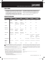
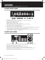
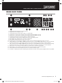
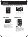
260 MKII, B300H, B800H, B115 MKII, B410 MKII, B810 MKII
OWNER’S MANUAL
B300H
B800H
B410 MKII
260 MKII
B115 MKII
B810 MKII
BASS GUITAR AMP HEADS AND CABS
w w w. a c o u s t i c a m p l i f i c a t i o n . c o m
9779 260MKII B300H B800H B115MKII B410MKII B810MKII Owner's Manual.indd 1
7/13/12 4:21 PM
260 MKII, B300H, B800H, B115 MKII, B410 MKII, B810 MKII | OWNER’S MANUAL
IMPORTANT SAFETY INSTRUCTIONS
DANGER
Exposure to extremely high noise levels may cause permanent hearing loss. Individuals
vary considerably to noise-induced hearing loss but most will lose some hearing if
exposed to intense noise for a sufficient period of time.
The U.S. Government’s Occupational Safety and Health Administration (OSHA) has
specified the following permissible noise level exposures:
DURATION PER DAY (HOURS) 864321
SOUND LEVEL (dB)
90939597100
103
According to OSHA, any exposure in the above permissible limits could result in some
hearing loss. Ear plugs or protectors in the ear canal or over the ears must be worn
when operating this amplification system in order to prevent a permanent hearing
loss. If exposure in excess of the limits as put forth above, to insure against potentially
harmful exposure to high sound pressure levels, it is recommended that all persons
exposed to equipment capable of inducing high sound pressure levels, such as this
amplification system, be protected by hearing protectors while this unit is in operation.
1.
2.
3.
4.
5.
6.
7.
8.
9.
10.
Read all safety and operating instructions before using this product.
All safety and operating instructions should be kept for future reference.
Read and understand all warnings listed on the operating instructions.
Follow all operating instructions to operate this product.
This product should not be used near water, i.e. a bathtub, sink, swimming pool, wet
basement, etc.
Use only a dry cloth to clean this product.
Do not block any ventilation openings. The product should not be placed flat against
a wall or placed in a built-in enclosure that will impede the flow of cooling air.
Do not install this product near any heat sources, such as radiators, heat registers,
stoves or any other apparatus (including heat–producing amplifiers) that produces
heat.
Do not defeat the safety purpose of the polarized or grounding-type plug. A
polarized plug has two blades with one wider than the other. A grounding-type plug
has two blades and a third grounding prong. The wide blade or the third prong are
provided for your safety. If the provided plug does not fit into your outlet, consult
an electrician for replacement of the obsolete outlet.
Protect the power cord being walked on or pinched, particularly at plugs,
convenience receptacles and the point where they exit from the apparatus. Do not
break the ground pin of the power supply cord.
THIS SYMBOL IS INTENDED TO ALERT THE USER TO THE PRESENCE OF NON-INSULATED
“DANGEROUS VOLTAGE” WITHIN THE PRODUCT’S ENCLOSURE THAT MAY BE OF
SUFFICIENT MAGNITUDE TO CONSTITUTE A RISK OF ELECTRIC SHOCK TO PERSONS
THIS SYMBOL IS INTENDED TO ALERT THE USER TO THE PRESENCE OF IMPORTANT
OPERATING AND MAINTENANCE (SERVICING) INSTRUCTIONS IN THE LITERATURE
ACCOMPANYING THE UNIT.
APPARATUS SHALL NOT BE EXPOSED TO DRIPPING OR SPLASHING AND THAT NO
OBJECTS FILLED WITH LIQUIDS, SUCH AS VASES, SHALL BE PLACED ON THE APPARATUS.
11. Only use attachments specified by the manufacturer.
12. When a cart is used, use caution when moving cart/apparatus
combination to avoid injury from tip-over.
13. Unplug this apparatus during lightning storms or when unused
for long periods of time.
14. Care should be taken so that objects do not fall and liquids are not spilled
into the unit through the ventilation ports or any other openings.
15. Refer all servicing to a qualified service professional. Servicing is required when
the apparatus does not operate normally or has been damaged in any way,
including damage to the power cord or plug, damage due to liquids spilled or
objects dropped inside the unit, dropping the unit, or anything else that interrupts
normal use of the unit.
16. WARNING: To reduce the risk of fire or electric shock, do not expose this apparatus
to rain or moisture.
17. When the MAINS plug, or an appliance coupler is used as the disconnect device, the
disconnect device shall remain readily operable.
18. Protective Ground Terminal: The apparatus shall be connected to an AC main socket
with a protective earth ground connection.
IMPORTANTES INSTRUCTIONS DE SECURITE
DANGER
L’exposition a des niveaux eleves de bruit peut provoquer une perte permanente
de l’audition, Chaque organisme humain reagit differemment quant a la perte de
l’audition, mais quasiment tout le monde subit une diminution de l’acuite auditive
lors d’une exposition suffisamment longue au bruit intense. Les autorites competentes
en reglementation de bruit ont defini les expositions tolerees aux niveaux de bruits:
DURE EN HEURES PAR JOUR
8
6
4
3
INIVEAU SONORE CONTINU EN dB 90
93
95
97
2
1
100 103
Selon les autorites, toute exposition dans les limites citees ci-dessus, peuvent provoquer
certaines pertes d’audition. Des bouchons ou protections dans l’appareil auditif ou
sur l’oreille doivent etre portes lors de l’utilisation de ce systeme d’amplification afin
de prevenir le risque de perte permanente de l’audition, Dans le cas d’expositions
superieures aux limites precitees il est recommande, afin de se premunir contre les
expositions aux pressions acoustiques elevees potentiellement dangeureuses, aux
personnes exposees aux equipements capables de delivrer de telles puissances, tels ce
systeme d’amplification en fonctionnement, de proteger l’appareil auditif.
1. Lire avec attention toutes les recommandations et précautions d’emploi avant
d’utiliser ce produit.
2. Toutes les recommandations et précautions d’emploi doivent être conservées afin de
pouvoir s’y reporter si nécessaire.
3. Lire et comprendre tous les avertissements énumérés dans les précautions d’emploi.
4. Suivre toutes les précautions d’emploi pour utiliser ce produit.
5. Ce produit ne doit pas être utilisé près d’eau, comme par exemple baignoires, éviers,
piscine, sous-sol humides ... Etc.
6. Utiliser exclusivement un chiffon sec pour nettoyer ce produit.
7. Ne bloquér aucune ouverture de ventilation. Ne pas placer le produit tout contre
un mur ou dans une enceinte fernée, cela gênerait le flux d’air nécessaire au
refroidissement.
8. Ne pas placer le produit près de toute source de chaeur telle que radiateurs, arrivées
d’air chaud, fourneaux ou autres appareils générant de la chaleur (incluant les
amplificateurs producteurs de chaleur).
9. Ne pas négliger la sécurité que procure un branchement polarisé ou avec
raccordement à la terre, Un branchement polarisé comprend deux fiches dont l’une
est plus large que l’autre. Un branchement à la terre comprend deux fiches plus une
troisième reliée à la terre. Si la fiche secteur fournie ne s’insert pas dans votre prise
de courant. consulter un ‘électricien afin de remplacer votre prise obsolète.
10. Protéger le cordon d’alimentation de tout écrasement ou pincement, particulièrement
au niveau des fiches, des réceptacles utilisés et à l’endroit de sortie de l’appareil. Ne
pas casser la fiche de terre ducordon d’alimentation.
2
CE SYMBOLE APOUR BUT D’AVERTIR L’UTILISATEUR DE LA PRESENCE DE VOLTAGE
DANGEREUX NON-ISOLE A L’INTERIEUR DE CE PRODUIT QUI PEUT ETRE DE PUISSANCE
SUFFISAMMENT IMPORTANTE POUR PROVOQUER UN CHOC ELECTRIQUE AUX PERSONNES
CE SYMBOLE APOUR BUT D’AVERTIR L’UTILISATEUR DE LA PRESENCE D’INSTRUCTIONS
D’UTILISATION ET DE MAINTENANCE DANS LES DOCUMENTS FOURNIS AVEC CE PRODUIT
AFIN DE REDUIRE LES RISQUÉ D’INCENDIE ET DE DECHARGE
ELECTRIQUE, NE PAS EXPOSER CET APPAREIL ALA PLUIE OU A L’HUMIDITE
11. Utiliser uniquement les accessoires spécifiés par le constructeur.
12. Utiliser uniquement avec le chariot de transport, le support, le trépied,
la console ou la table spécifiés par le constructeur ou vendus avec
l’appareil. Lors de l’utilisation d’un chariot, bouger avec précaution
l’ensemble chariotlappareil afin d’éviter les dommages d’un renversement.
13. Débrancher cet appareil lors d’orages ou s’il n’est pas utilisé pendant
une longue période.
14. Des précautions doivent être prises afin qu’aucun objet ne tombe et qu’aucun liquide
ne se répande à l’intérieur de l’appareil par les orifics de ventilation ou n’importe
quelle autre ouverture.
15. Pour toutes interventions techniques s’adresser à un technicien qualifié.L’intervention
technique est nécessaire lorsque l’appareil aété endommagé de n’importe quelle
façon, comme par exemple si le cordon secteur ou sa fiche sont détériorés,si du
liquide acoulé ou si des objets sont tombés à l’intérieur de l’apparei1 ,si l’appareil a
été exposé à la pluie ou à l’humidité, s’il ne fonctionne pas normalement ou s’il est
tombé.
16. ATTENTION: Pour réduire le risque d’incendie ou de choc electrique ne pas exposer
l’appareil à la pluie ou à l’humidité.
17. Quand La prise MAINS, au coupler, est utilisé pour la source d’alimentation
êlectrique. Il est conseillê de garder cette prise facilement accessible.
18. Borne de terre de protection: L’appareil doit être connecté à un connecteur AC
principale avec un raccordement à la terre de protection.
www.acousticamplification.com
9779 260MKII B300H B800H B115MKII B410MKII B810MKII Owner's Manual.indd 2
7/13/12 4:21 PM
260 MKII, B300H, B800H, B115 MKII, B410 MKII, B810 MKII | OWNER’S MANUAL
WELCOME
Congratulations on your purchase of a new Acoustic electric
bass amplifier. Founded as the Acoustic Control Corporation
in Van Nuys, California in 1967, Acoustic is the rig of choice
for many legendary touring musicians. If you’re new to
Acoustic amps, we encourage you to get in tune with its
rich heritage at www.acousticamplification.com/history.cfm
Your comments are important. We constantly improve our
products based on feedback from musicians like you. Please
feel free to contact us at www.acousticamplification.com
or send us an email at [email protected].
Welcome to Acoustic, the Pro’s Tone™.
SPECIFICATIONS
Model
260 MKII
B300H
B800H
B115 MKII
B410 MKII
B810 MKII
Power
100 Watts
@ 4 Ohms
300 Watts
@ 4 Ohms
800 Watts
@ 4 Ohms
N/A
N/A
N/A
Equalizer
3 Band EQ
+ Shape Switch
6 Band EQ
+ Shape Switch &
Adjustable Notch
6 Band EQ
+ Shape Switch &
Adjustable Notch
N/A
N/A
N/A
Overdrive
Yes
Yes
Yes
N/A
N/A
N/A
Effects loop
Yes
Yes
Yes
N/A
N/A
N/A
Compression
Acousti-Comp,
Non-adjustable
Acousti-Comp,
Adjustable/
Defeatable
Acousti-Comp,
Adjustable/
Defeatable
N/A
N/A
N/A
XLR Direct Out
Pre/Post, Level
and Ground Lift
Pre/Post, Level
and Ground Lift
Pre/Post, Level
and Ground Lift
N/A
N/A
N/A
Speaker
10”, 100W , 4 Ω
N/A
N/A
1x15”, 450W, 8 Ω
4x10”, 150W, 8 Ω
8x10”, 150W, 8 Ω
600W total
power handling
@8Ω
1200W total
power handling
@4Ω
Hi Frequency Horn
N/A
N/A
N/A
Piezo, defeatable
Piezo, defeatable
Piezo, defeatable
Dimensions
WxDxH
13.2“x9.1”x5.3”
21.1”x12”x5.9”
21.1”x15.2”x 6.5”
24.1”x16.3”x 28.3”
24.1”x16.3”x 25.8”
24.1”x16.3”x 48”
Weight
12.9 lbs.
27.5 lbs.
43.5 lbs.
77 lbs.
78 lbs.
143 lbs.
3
Three Year Limited Warranty: Subject to the limitations set forth below, Acoustic®
hereby represents and warrants that the components of this product shall be
free from defects in workmanship and materials, including implied warranties of
merchantability or fitness for a particular purpose, subject to normal use and service, for
three (3) years to the original owner from the date of purchase.
Retailer and manufacturer shall not be liable for damages based upon inconvenience,
loss of use of product, loss of time, interrupted operation or commercial loss or any
FCC Statements
1. Caution: Changes or modifications to this unit not expressly approved by the party responsible for compliance
could void the user’s authority to operate the equipment.
2. Note: This equipment has been tested and found to comply with the limits for a Class B digital device,
pursuant to Part 15 of the FCC Rules. These limits are designed to provide reasonable protection against
harmful interference in a residential installation. This equipment generate, uses, and can radiate radio
frequency energy and , in not installed and used in accordance with the instructions, may cause harmful
interference to radio communications. However, there is no guarantee that interference will not occur in
a particular installation. If this equipment does cause harmful interference to radio or television reception,
which can be determined by turning the equipment off and on, the user is encouraged to try to correct the
interference by one or more of the following measures:
• Reorient or relocate the receiving antenna
• Increase the separation between the equipment and receiver
• Connect the equipment into an outlet on a circuit different from that to which the receiver is connected
• Consult the dealer or an experienced radio/TV technician for help
other incidental or consequential damages including but not limited to lost profits,
downtime, goodwill, damage to or replacement of equipment and property, and any
costs of recovering, reprogramming, or reproducing any program or data stored in
equipment that is used with Acoustic® products. This guarantee gives you specific
legal rights. You may have other legal rights which vary from state to state. Some states
do not allow limitations on how long an implied warranty lasts, so the above limitation
may not apply to you.
Acoustic
P.O. Box 5111
Thousand Oaks, CA
91359-5111
All trademarks and registered trademarks mentioned herein are recognized as the property
of their respective holders.
1204 - 9779
www.acousticamplification.com
9779 260MKII B300H B800H B115MKII B410MKII B810MKII Owner's Manual.indd 3
3
7/13/12 4:21 PM
260 MKII, B300H, B800H, B115 MKII, B410 MKII, B810 MKII | OWNER’S MANUAL
260 MKII FRONT PANEL
1
2
3
4
5
6
7
8
9
10
11 12
13
Bass Input: ¼” two-conductor jack
-10 dB pad: Reduces input sensitivity for use with active electronics basses or high output pickups
Volume: Adjusts the overall volume level of the amplifier
Overdrive: Controls the amount of overdrive
On/Off Switch: Activates the Overdrive circuit Overdrive Level: Controls the mix of overdrive to clean signal
Shape: This button decreases the level of the mid frequencies creating an alternate EQ curve
Low: This control increases or decreases bass frequencies
Mid: This control increases or decreases high midrange frequencies
High: This control increases or decreases treble frequencies
Aux Input: This 3-conductor ⅛” media input jack will allow you to plug in a CD, MP3 player, or any other source so you can
practice along. To control the volume of the source, adjust the output volume of the device. Note: Turn the volume all the way
down before plugging in your guitar and adjust the volume according to your taste.
12. Headphone Output: ⅛” 3-conductor jack for plug¬ging in headphones. When used, it will disconnect the internal speaker
13. Power Switch: When lit, the amplifier is on and ready for use.
1.
2.
3.
4.
5.
6.
7.
8.
9.
10.
11.
260 MKII BACK PANEL
1
4
1.
2.
3.
4.
5.
6.
7.
8.
2
3
4
5
6
7
8
AC power connection and Fuse: Connect included IEC power cable here. Fuse cap contains fuse for circuit protection
Speaker Out: ¼” speaker jack for attaching external speaker (minimum 4 Ohm load)
Direct Output: XLR direct balanced output connector jack
Pre/Post EQ Switch: Switches Balanced Output between pre and post EQ operation
Effects Send: ¼” two-conductor jack sends signal to an external effects or signal processing device
Ground Lift: Lifts the ground from the XLR direct output. Useful for eliminating hum when the direct out is used
XLR Level: Adjusts the level of the direct output signal
Effects Return: ¼” two-conductor jack returns signal from an external effects or signal processing device
www.acousticamplification.com
9779 260MKII B300H B800H B115MKII B410MKII B810MKII Owner's Manual.indd 4
7/13/12 4:21 PM
260 MKII, B300H, B800H, B115 MKII, B410 MKII, B810 MKII | OWNER’S MANUAL
B300H FRONT PANEL
4
1
1.
2.
3.
4.
5.
6.
7.
8.
9.
10.
11.
12.
13.
14.
2
3
5
6
7
8
9
10
11 12
13
14
Bass Input: ¼” two-conductor jack
-10 dB pad: Reduces input sensitivity for use with active electronics basses or high output pickups
Gain: Adjusts the level of preamp input gain
Clipping Light: Lights in red when hi gain creates preamp clipping
Compression Indicator Light: Indicates the level of compression when the compressor is engaged (6)
Compressor On/Off: Engages compression circuitry when button is depressed
Overdrive: Controls the amount of overdrive
On/Off Switch: Activates the Overdrive circuit Overdrive Level: Controls the mix of overdrive to clean signal
Volume: Adjusts the overall volume level of the amplifier
Notch: Adjusts the -10dB notch frequency from 50Hz to 1kHz.
Shape: This button decreases the level of the mid frequencies creating an alternate EQ curve
Equalizer: These 6 knobs increase or decrease the level of the associated frequency.
Power Switch: When lit, the amplifier is on and ready for use.
B300H BACK PANEL
1
2
4
5
6
7
3
8
9
10
11
12
1.
2.
3.
4.
5.
6.
7.
8.
9.
10.
AC power connection and Fuse: Connect included IEC power cable here. Fuse cap contains fuse for circuit protection
Speaker Out: ¼” speaker jack for attaching external speaker (minimum 4 Ohm total load)
Speaker Out: ¼” speaker jack for attaching external speaker (minimum 4 Ohm total load)
Direct Output: XLR direct balanced output connector jack
Pre/Post EQ Switch: Switches Balanced Output between pre and post EQ operation
Effects Return: ¼” two-conductor jack returns signal from an external effects or signal processing device
Effects Send: ¼” two-conductor jack sends signal to an external effects or signal processing device
Ground Lift: Lifts the ground from the XLR direct output. Useful for eliminating hum when the direct out is used
Direct Output Level: Adjusts the level of the direct output signal
Link In: Input from another B300H or B800H amp head. Allows user to run the B300H in Slave Mode controlled from another amp head.
This allows the user to link 2 heads together for more power and speakers controlled from one master amplifier.
11. Link Out: Output to another B300H or B800H amp head. Allows user to run the B300H in Master Mode to control another amp head.
This allows the user to link 2 heads together for more power and speakers controlled from one master amplifier
12. Footswitch: ¼” Tip, Ring, Sleeve jack for attaching optional 2 button footswitch. Controls Overdrive On/Off and Effects Loop On/Off
www.acousticamplification.com
9779 260MKII B300H B800H B115MKII B410MKII B810MKII Owner's Manual.indd 5
5
7/13/12 4:21 PM
260 MKII, B300H, B800H, B115 MKII, B410 MKII, B810 MKII | OWNER’S MANUAL
B800H FRONT PANEL
3
INPUT
6
7
GAIN
OVERDRIVE
OVERDRIVE
LEVEL
VOLUME
NOTCH
40Hz
120Hz
800Hz
350Hz
2KHz
5KHz
POWER
CLIP
–10dB
PAD
MUTE
SWITCH
COMPRESSOR
ON/OFF
ON/OFF
ON/OFF
SHAPE
EQUALIZER
B800H
1
1.
2.
3.
4.
5.
6.
7.
8.
9.
10.
11.
12.
13.
14.
15.
16.
17.
6
2
4
5
8
9 10 11
12 13 14 15
16
17
Bass Input: ¼” two-conductor jack
-10 dB pad: Reduces input sensitivity for use with active electronics basses or high output pickups
Mute Indicator Light: Indicates B800H is muted
Mute Switch: Mutes sound from the B800H when switch is depressed
Gain: Adjusts the level of preamp input gain
Clipping Light: Lights in red when hi gain creates preamp clipping
Compression Indicator Light: Indicates the level of compression when the compressor is engaged (8)
Compressor On/Off: Engages compression circuitry when button is depressed
Overdrive: Controls the amount of overdrive
On/Off Switch: Activates the Overdrive circuit Overdrive Level: Controls the mix of overdrive to clean signal
Volume: Adjusts the overall volume level of the amplifier
Notch On/Off Switch: Activates Notch Frequency control when depressed
Notch: Adjusts the -10dB notch frequency from 50Hz to 1kHz.
Shape: This button decreases the level of the mid frequencies creating an alternate EQ curve
Equalizer: These 6 knobs increase or decrease the level of the associated frequency.
Power Switch: When lit, the amplifier is on and ready for use.
www.acousticamplification.com
9779 260MKII B300H B800H B115MKII B410MKII B810MKII Owner's Manual.indd 6
7/13/12 4:21 PM
260 MKII, B300H, B800H, B115 MKII, B410 MKII, B810 MKII | OWNER’S MANUAL
B800H BACK PANEL
1
2
1.
2.
3.
4.
5.
6.
7.
8.
9.
10.
11.
12.
13.
14.
15.
16.
4
3
5
7
6
11 12
8
9
14 13
10
16 15
Circuit Breaker: Circuit Breaker for circuit protection
AC Cable: Connect to AC power source
Locking Combo Speaker Jack: Accepts locking or ¼” speaker cable
Speaker Out: ¼” speaker jack for attaching external speaker (minimum 4 Ohm total load)
Speaker Out: ¼” speaker jack for attaching external speaker (minimum 4 Ohm total load)
Cooling Fan: Cooling fan cools internal circuitry for optimal performance
Pre/Post EQ switch: Switches Balanced Output between pre and post EQ operation
Direct Output Level: Adjusts the level of the direct output signal
Direct Output: XLR direct balanced output connector jack
Ground Lift: Lifts the ground from the XLR direct output. Useful for eliminating hum when the direct out is used
Link Out: Output to another B300H or B800H amp head. Allows user to run the B300H in Master Mode to control another amp
head. This allows the user to link 2 heads together for more power and speakers controlled from one master amplifier
Link In: Input from another B300H or B800H amp head. Allows user to run the B300H in Slave Mode controlled from another amp
head. This allows the user to link 2 heads together for more power and speakers controlled from one master amplifier.
Effects Send: ¼” two-conductor jack sends signal to an external effects or signal processing device
Effects Return: ¼” two-conductor jack returns signal from an external effects or signal processing device
Tuner Send: Attach electronic instrument tuner via ¼” 2 conductor instrument cable.
Footswitch: ¼” Tip, Ring, Sleeve jack for attaching optional 2 button footswitch. Controls Overdrive On/Off and Effects Loop On/Off
www.acousticamplification.com
9779 260MKII B300H B800H B115MKII B410MKII B810MKII Owner's Manual.indd 7
7
7/13/12 4:21 PM
260 MKII, B300H, B800H, B115 MKII, B410 MKII, B810 MKII | OWNER’S MANUAL
260 SPEAKER CABINET JACK PLATE
B115 MKII REAR JACK PLATE
1
1
1. ¼” Speaker Input Jack: Connect 260 MKII head to
260 Cabinet via ¼” speaker cable connector
B410 MKII JACK PLATE
1
2
3
1. Horn On/Off Switch: Engages Piezo horn when in
depressed position
Note: Power handling is 450 watts @ 8 ohms
2. ¼” Speaker Input Jack: Connect amplifier head to
B115 MKII Cabinet via ¼” speaker cable connector
3. Parallel ¼” Speaker Jack: Connect B115 MK speaker
cabinet to another speaker cabinet (in parallel) via
¼” speaker cable connector
B810 MKII JACK PLATE
3
1. Horn On/Off Switch: Engages Piezo horn when in
depressed position
Note: Power handling is 600 watts @ 8 ohms
2. ¼” Speaker Input Jack: Connect amplifier head to
B410 MKII Cabinet via ¼” speaker cable connector
3. Parallel ¼” Speaker Jack: Connect B410 MKII speaker
cabinet to another speaker cabinet (in parallel) via
¼” speaker cable connector
8
2
1
2
3
4
1. Horn On/Off Switch: Engages Piezo horn when in
depressed position
Note: Power handling is 1200 watts @ 4 ohms
2. ¼” Speaker Input Jack: Connect amplifier head to
B410 MKII Cabinet via ¼” speaker cable connector
3. Parallel ¼” Speaker Jack: Connect B410 MKII speaker
cabinet to another speaker cabinet (in parallel) via
¼” speaker cable connector
4. Combo Locking Speaker Connector Jack: Connect
amplifier head to B810 MKII via locking connector or
¼” speaker connector
www.acousticamplification.com
9779 260MKII B300H B800H B115MKII B410MKII B810MKII Owner's Manual.indd 8
7/13/12 4:21 PM


![View User`s Manual [US] - Acoustic Amplification](http://vs1.manualzilla.com/store/data/005985253_1-d8c5e8224596dc85b40fdb714a0c7e6f-150x150.png)
![View User`s Manual [US] - Acoustic Amplification](http://vs1.manualzilla.com/store/data/005687953_1-09ed6117760df16c9056fa1c8c49b775-150x150.png)
![View User`s Manual [US] - Acoustic Amplification](http://vs1.manualzilla.com/store/data/005805370_1-0fda88921e56c0c9a0d78a1aaa3723de-150x150.png)
![View User`s Manual [US] - Acoustic Amplification](http://vs1.manualzilla.com/store/data/005929580_1-14523f44a960f194cc16791ff2ace09d-150x150.png)