1
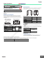
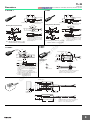
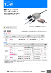
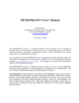
Flat Inductive Proximity Sensor
TL-W
CSM_TL-W_DS_E_6_1
Standard Flat Sensors in
Many Different Variations
m
• Only 6 mm thick yet provides a sensing distance of
3 mm (TL-W3MC1).
• Aluminum die-cast models also available.
co
Be sure to read Safety Precautions on
page 7.
s.
Ordering Information
Model
Operation mode
Sensing distance
NO
Unshielded
TL-W5MD1 2M
on
l
3 mm
Model
Operation mode
NO
NC
20 mm
---
TL-W3MC1 2M
*1
*2
TL-W3MC2 2M
TL-W5MC1 2M
*1
*2
TL-W5MC2 2M
TL-W20ME1 2M
*1
TL-W20ME2 2M
DC 3-wire, NPN
5 mm
Shielded
TL-W5MD2 2M *2
*1
TL-W1R5MC1 2M *2
1.5 mm
Unshielded
NC
Output configuration
in
ec
Sensing distance
om
DC 3-Wire Models
Appearance
*1
*2
po
5 mm
ne
Appearance
nt
Sensors [Refer to Dimensions on page 8.]
DC 2-Wire Models
DC 3-wire, NPN
TL-W5E1 2M
TL-W5E2 2M
DC 3-wire, PNP
TL-W5F1 2M
TL-W5F2 2M
*1
*2
*1
5 mm
*1. Models with a different frequency are also available to prevent mutual interference. The model numbers are TL-W@M@@5 (e.g., TL-W5MD15).
*2. Models with robotics cables are also available. The model numbers are TL-W@MC1-R (e.g., TL-W1R5MC1-R).
1
TL-W
Ratings and Specifications
DC 2-Wire Models
Item
Model
TL-W5MD@
Sensing distance
5 mm ±10%
Set distance
0 to 4 mm
Differential travel
10% max. of sensing distance
Detectable object
Ferrous metal (The sensing distance decreases with non-ferrous metal. Refer to Engineering Data on page
5.)
Iron, 18 × 18 × 1 mm
Response frequency *1
500 Hz
Power supply voltage
(operating voltage range)
12 to 24 VDC (10 to 30 VDC), ripple (p-p): 10% max.
Leakage current
0.8 mA max.
Control
output
Load current
3 to 100 mA
Residual voltage
3.3 V max. (under load current of 100 mA with cable length of 2 m)
m
Standard sensing object
D1 Models: Operation indicator (red), Setting indicator (green)
D2 Models: Operation indicator (red)
Operation mode (with sensing
object approaching)
D1 Models: NO
D2 Models: NC
Protection circuits
Load short-circuit protection, Surge suppressor
Ambient temperature range
Operating/Storage: −25 to 70°C (with no icing or condensation) *2
Ambient humidity range
Operating/Storage: 35% to 95% (with no condensation)
Temperature influence
±10% max. of sensing distance at 23°C in the temperature range of −25 to 70°C
Voltage influence
±2.5% max. of sensing distance at rated voltage in the rated voltage ±15% range
Insulation resistance
50 MΩ min. (at 500 VDC) between current-carrying parts and case
Dielectric strength
1,000 VAC for 1 min between current-carrying parts and case
Vibration resistance
Destruction: 10 to 55 Hz, 1.5-mm double amplitude for 2 hours each in X, Y, and Z directions
Shock resistance
Destruction: 500 m/s2 3 times each in X, Y, and Z directions
Degree of protection
IEC 60529 IP67, in-house standards: oil-resistant *2
Connection method
Pre-wired Models (Standard cable length: 2 m)
Weight (packed state)
Approx. 45 g
Accessories
om
po
ne
nt
s.
Refer to the timing charts under I/O Circuit Diagrams on page 6 for details.
Case
Heat-resistant ABS
in
ec
Materials
co
Indicators
Sensing surface
Instruction manual
on
l
*1. The response frequency is an average value.
Measurement conditions are as follows: standard sensing object, a distance of twice the standard sensing object, and a set distance of half the sensing distance.
*2. For environments that require oil resistance, the upper limit of the ambient operating temperature range is 40°C.
2
TL-W
DC 3-Wire Models
Model
Item
TL-W1R5MC1
TL-W3MC@
TL-W5E1, TL-W5E2
TL-W5F1, TL-W5F2
TL-W5MC@
TL-W20ME1
TL-W20ME2
Sensing distance
1.5 mm ±10%
3 mm ±10%
5 mm ±10%
20 mm ±10%
Set distance
0 to 1.2 mm
0 to 2.4 mm
0 to 4 mm
0 to 16 mm
Differential travel
10% max. of sensing distance
Detectable object
Ferrous metal (The sensing distance decreases with non-ferrous metal. Refer to Engineering Data on page 5.)
Standard sensing
object
Iron, 8 × 8 × 1 mm
Iron, 12 × 12 × 1 mm Iron, 18 × 18 × 1 mm
Response
frequency
1 kHz min.
600 Hz min.
1% to 15% of
sensing distance
Iron, 50 × 50 ×
1 mm
300 Hz min.
40 Hz min.
Power supply voltage (operating volt- 12 to 24 VDC (10 to 30 VDC), ripple (p-p): 10% max.
age range)
12 to 24 VDC (10 to 30 VDC),
ripple (p-p): 20% max.
12 to 24 VDC (10
to 30 VDC), ripple
(p-p): 10% max.
Current
consumption
8 mA at 12 VDC,
15 mA at 24 VDC
10 mA max.
15 mA max. at 24 VDC (no-load)
NPN open collector
100 mA max. at 30 VDC max.
NPN open collector
50 mA max. at
12 VDC (30 VDC
max.)
100 mA max. at
24 VDC (30 VDC
max.)
200 mA
Residual 1 V max. (under load current of 100 mA with
voltage cable length of 2 m)
co
1 V max. (under
1 V max. (under load
2 V max. (under load current of load current of
current of 50 mA with
200 mA with cable length of 2 m) 200 mA with cacable length of 2 m)
ble length of 2 m)
Detection indicator (red)
Operation mode
(with sensing object approaching)
NO
Protection circuits
Reverse polarity protection, Surge suppressor
Ambient
temperature range
Operating/Storage: −25 to 70°C (with no icing or condensation) *
Ambient
humidity range
Operating/Storage: 35% to 95% (with no condensation)
Temperature
influence
±10% max. of sensing distance at 23°C in the temperature range of −25 to 70°C
Voltage influence
±2.5% max. of sens±2.5% max. of sensing distance at rated volt- ing distance at rated
age in the rated voltage ±10% range
voltage in the rated
voltage ±20% range
Insulation
resistance
50 MΩ min. (at 500 VDC) between current-carrying parts and case
ne
Indicators
C1 Models: NO
C2/B2 Models: NC
E1/F1 Models: NO
E2/F2 Models: NC
±2.5% max. of sensing distance at rated voltage in
the rated voltage ±10% range
on
l
in
ec
om
po
Refer to the timing charts under I/O Circuit Diagrams on page 6 for details.
Dielectric strength
1,000 VAC, 50/60 Hz for 1 minute between current-carrying parts and case
Vibration
resistance
Destruction: 10 to 55 Hz, 1.5-mm double amplitude for 2 hours each in X, Y, and Z directions
Shock resistance
Destruction: 500 m/s2 3 times each in X, Y, and Z directions
Degree of
protection
IEC 60529 IP67, in-house standards: oil-resistant *
Connection
method
Pre-wired Models (Standard cable length: 2 m)
Weight
(packed state)
Approx. 30 g
Materials
Case
Heat-resistant ABS
Sensing
surface
Heat-resistant ABS
Accessories
100 mA max. at
12 VDC
200 mA max. at
24 VDC
s.
Control
output
m
15 mA max. at 24 VDC (no-load)
nt
Load
current
500 Hz min.
Mounting Bracket, Instruction manual
Approx. 45 g
Destruction:
500 m/s2 10
times each in X,
Y, and Z directions
Approx. 70 g
Approx. 180 g
Aluminum die-cast
Heat-resistant
ABS
Instruction manual
* For environments that require oil resistance, the upper limit of the ambient operating temperature range is 40°C.
3
TL-W
Engineering Data (Typical)
Sensing Area
4
Y
X
3
TL-W5MC1/-W5MD@
Distance X (mm)
TL-W3MC1
Distance X (mm)
Distance X (mm)
TL-W1R5MC1
4
Y
X
3
6
5
4
Y
X
2
2
1
1
3
2
1
0
2
TL-W5E/-W5F
−4
−2
0
2
4
Distance X (mm)
5
4
30
Y
X
25
20
X
1
5
−2
0
2
Sensing head
4
6
8 Distance
Y (mm)
−20 −15 −10
om
−4
0
2
4
6
8 Distance
Y (mm)
−5
0
5
Sensing head
10
15
20 Distance
Y (mm)
in
ec
−6
po
10
−2
ne
15
2
−4
nt
Y
3
−6
Sensing head
TL-W20@
6
−10 −8
−8
Distance
Y (mm)
Sensing head
on
l
Distance X (mm)
−6
4 Distance Y
(mm)
Sensing head
m
−2
co
−4
s.
−6
4
TL-W
Influence of Sensing Object Size and Material
d×
d
t = 1 mm
X
3
4
d×
d
TL-W5MC1
Distance X (mm)
4
TL-W3MC1
Distance X (mm)
Distance X (mm)
TL-W1R5MC1
t = 1 mm
X
3
Iron
7
d×
d
t = 1 mm
X
6
5
Iron
Stainless steel (SUS304)
Stainless steel
(SUS304)
4
2
2
Brass
Iron
Stainless steel (SUS304)
1
3
Brass
Aluminum
Copper
1
Brass
Aluminum
2
Copper
1
Copper
Aluminum
Iron
5
Stainless steel
(SUS304)
4
24
22
t = 1 mm
X
Iron
20
18
16
14
12
3
Brass
ne
8
6
Aluminum
0
15
20
25
30
35
40 45
Side length of sensing object: d (mm)
10
20
30
40
50
60
70
80 90
Side length of sensing object: d (mm)
om
10
in
ec
5
po
2
Brass
Aluminum
4
1
20
30
40
50
60
Side length of sensing object: d (mm)
Stainless steel
(SUS304)
10
2
0
d×
d
10
m
TL-W20@
t = 1 mm
0
co
X
20
30
40
50
60
Side length of sensing object: d (mm)
s.
d×
d
10
on
l
Distance X (mm)
TL-W5E@/-W5F@/-W5MD@
6
0
20
30
40
50
60
Side length of sensing object: d (mm)
nt
10
Distance X (mm)
0
5
TL-W
I/O Circuit Diagrams
DC 2-Wire Models
Operation mode
Model
Timing chart
Non-sensing area
Unstable Set position
Stable sensing
sensing
area
area
Output circuit
Proximity Sensor
Sensing
object
(%)
NO
TL-W5MD1
100
Rated
sensing
distance
80 (TYP)
0
ON
OFF
Brown
ON
OFF
Operation indicator (red)
ON
OFF
Load
Setting indicator (green)
+V
Proximity
Sensor
main
circuit
Control output
Blue
Non-sensing area
Sensing area
0V
Proximity Sensor
Note: The load can be connected to either
the +V or 0 V side.
Sensing
object
TL-W5MD2
100
Rated sensing distance
0
ON
Operation indicator (red)
ON
OFF
Control output
Timing chart
Sensing object
NO
TL-W1R5MC1
TL-W3MC1
TL-W5MC1
Present
Not present
Output transistor
(load)
ON
OFF
Sensing object
TL-W3MC2
TL-W5MC2
Present
Not present
Output transistor
(load)
ON
OFF
Detection indicator
(red)
ON
OFF
om
NC
TL-W5E1
TL-W20ME1
on
l
NC
in
ec
Sensing object
NO
TL-W5E2
TL-W20ME2
TL-W5F1
NC
TL-W5F2
+V
Load
Black *
Proximity
Sensor
main
circuit
Output
Blue
0V
* Load current: 100 mA max.
Operate
Reset
Output voltage (between
black and blue leads)
High
Low
Detection indicator (red)
ON
OFF
Brown
Operate
Reset
Load (between brown
and black leads)
Output voltage (between
black and blue leads)
High
Low
Detection indicator (red)
ON
OFF
+V
100 Ω
Load
Proximity
Sensor
main
circuit
4.7 kΩ
2.2 Ω
Present
Not present
Sensing object
Black*1
Output
*2
Blue
Tr
0V
*1. Load current: 200 mA max.
*2. When a transistor is connected.
Present
Not present
Operate
Reset
Load (between blue
and black leads)
Output voltage (between
blue and black leads)
High
Low
Detection indicator (red)
ON
OFF
Sensing object
Brown
100 Ω
Present
Not present
Load (between brown
and black leads)
Sensing object
NO
ON
OFF
po
Detection indicator (red)
Output circuit
nt
Model
ne
Operation mode
s.
DC 3-Wire Models
co
OFF
m
(%)
NC
Present
Not present
Load (between blue
and black leads)
Operate
Reset
Output voltage (between
blue and black leads)
High
Low
Detection indicator (red)
ON
OFF
Brown
+V
Tr
Proximity
Sensor
main
circuit
*2
Black
2.2 Ω
Output
*1
Load
4.7 kΩ
100 Ω
Blue
0V
*1. Load current: 200 mA max.
*2. When a transistor is connected.
6
TL-W
Safety Precautions
Refer to Warranty and Limitations of Liability.
WARNING
Mutual Interference
This product is not designed or rated for ensuring
safety of persons either directly or indirectly.
Do not use it for such purposes.
When installing Sensors face-to-face or side-by-side, ensure that the
minimum distances given in the following table are maintained.
B
A
Precautions for Correct Use
Do not use this product under ambient conditions that exceed the
ratings.
● Design
Influence of Surrounding Metal
l
Proximity
Sensor
Sensing
surface
n
s.
Sensing surface
Distance
TL-W1R5MC1
TL-W3MC@
TL-W5MD@
TL-W5MC1@
TL-W20ME@
TL-W5E@/-W5F@
l
Proximity
Sensor
A
B
75 (50)
90 (60)
25 (8)
30 (10)
120 (80)
60 (30)
200 (100)
50
200 (100)
35
Note: Values in parentheses apply to Sensors operating at different
frequencies.
nt
m
Model
co
Metals on Both Sides and
in Front of the Sensor
Metal on a Single Side
(Not Exceeding the Height
of the Sensor Surface)
Mutual Interference (Unit: mm)
m
When mounting the Sensor within a metal panel, ensure that the
clearances given in the following table are maintained. Failure to
maintain these distances may cause deterioration in the performance
of the Sensor.
● Mounting
l
2
3
m
0
5
on
l
8
12
20
16
0
in
ec
25
0
n
po
Distance
TL-W1R5MC1
TL-W3MC@
TL-W5MD@
TL-W5MC1
TL-W20ME@
TL-W5E@/-W5F@
om
Model
100
20
• Use M3 flat-head screws to mount the TL-W1R5MC1 and TLW3MC1.
• Do not exceed the torque in the following table when tightening the
resin cover screws.
ne
Influence of Surrounding Metal (Unit: mm)
Model
TL-W1R5MC1
TL-W3MC@
TL-W5MD@
TL-W20M@
Torque
0.98 N·m
1.5 N·m
● Adjustment
Turning ON the Power
An error pulse will occur (approximately 1 ms) if adjustments are
made when turning ON the power or making AND connections.
Applicable e-CON Connector Models and Manufacturers
The companies and model number of e-CON connections that can be used with Sensor cables are listed in the following table.
Confirm applicability when purchasing e-CON connectors for connection to Pre-wired Sensors.
Model
TL-W1R5@/-W3@
Tyco Electronics AMP K.K.
1-1473562-4 (red)
7
TL-W
(Unit: mm)
Dimensions
Tolerance class IT16 applies to dimensions in this data sheet unless otherwise specified.
TL-W1R5MC1
TL-W3MC@
25
16±0.2
5±0.2
27
17±0.2
3
5±0.2
Detection indicator
(red)
8
8
9
*
Mounting hole for M3
pan-head screw
90°
6 dia.
Mounting Bracket (Attachment)
7.8 1
5.5
Mounting hole for M3
pan-head screw
90°
6 dia.
6
7.8 1
3.2 dia.
*
9
Mounting Bracket (Attachment)
3.2
3.2 dia.
Indicator
Indicator
R1.6
R1.6 3.2
8
7
Note: Mounting hole dimension: 17 ±0.2.
Material: Stainless steel (SUS304)
5.5
Indicator
* 2.9-dia. vinyl-insulated round cable with
3 conductors (Conductor cross section:
0.14 mm2, Insulator diameter: 0.9 mm),
Standard length: 2 m
TL-W5MC@
TL-W5MD@
Note: Mounting hole dimension: 17 ±0.20.
Material: Stainless steel (SUS304)
nt
TL-W5E@
TL-W5F@
30.5
8.5
18
4.5
ne
Sensing
surface
*1
18
4
12±0.1
om
10
6.5
7.5
15
16-dia. sensing
surface
in
ec
on
l
(2)
50
*
4.2 dia.
8
*1. TL-W5MC1
4-dia. vinyl-insulated round cable with 3
conductors (Conductor cross section: 0.2 mm2,
Insulator diameter: 1.2 mm), Standard length: 2 m
TL-W5MD@
4-dia. vinyl-insulated round cable with 2
conductors (Conductor cross section: 0.3 mm2,
Insulation diameter: 1.3 mm), Standard length: 2 m
*2. C Models: Detection indicator (red)
D Models: Operation indicator (red),
Setting indicator (green)
10.5
8
10
4.5
Mounting Hole
Dimensions
12.5
Indicator
* 2.9-dia. vinyl-insulated round cable with
3 conductors (Conductor cross section:
0.14 mm2, Insulator diameter: 0.9 mm),
Standard length: 2 m
Detection indicator (red)
0
24.9 -0.4
po
3.5
5
Indicator *2
0.2
9
co
0.2
s.
5
10
m
R1.6
TL-W20ME@
8
Sensing surface
22.4
16
(See note.)
3.2
R1.6 3.2
Detection indicator
(red)
10
Sensing surface
22.4
16
(See note.)
3
3
15±0.2
10
Two, 4.5 dia.
4
7.2 dia.
* 4-dia. vinyl-insulated round cable with 3 conductors
(Conductor cross section: 0.2 mm2, Insulator
diameter: 1.2 mm), Standard length: 2 m
Sensing surface
40 30±0.1 18
5
27±0.1
5
6
20
Two, 5.5-dia.
mounting holes
Detection
indicator (red)
23
18
1
53
1.5
6-dia. vinyl-insulated round cable with 3 conductors
(Conductor cross section: 0.5 mm2, Insulator
diameter: 1.9 mm), Standard length: 2 m
8
Terms and Conditions of Sale
16.
nt
s.
15.
co
m
14.
ITY OR FITNESS FOR A PARTICULAR PURPOSE OF THE PRODUCTS.
BUYER ACKNOWLEDGES THAT IT ALONE HAS DETERMINED THAT THE
PRODUCTS WILL SUITABLY MEET THE REQUIREMENTS OF THEIR
INTENDED USE. Omron further disclaims all warranties and responsibility of
any type for claims or expenses based on infringement by the Products or otherwise of any intellectual property right. (c) Buyer Remedy. Omron’s sole obligation hereunder shall be, at Omron’s election, to (i) replace (in the form
originally shipped with Buyer responsible for labor charges for removal or
replacement thereof) the non-complying Product, (ii) repair the non-complying
Product, or (iii) repay or credit Buyer an amount equal to the purchase price of
the non-complying Product; provided that in no event shall Omron be responsible for warranty, repair, indemnity or any other claims or expenses regarding
the Products unless Omron’s analysis confirms that the Products were properly handled, stored, installed and maintained and not subject to contamination, abuse, misuse or inappropriate modification. Return of any Products by
Buyer must be approved in writing by Omron before shipment. Omron Companies shall not be liable for the suitability or unsuitability or the results from the
use of Products in combination with any electrical or electronic components,
circuits, system assemblies or any other materials or substances or environments. Any advice, recommendations or information given orally or in writing,
are not to be construed as an amendment or addition to the above warranty.
See http://www.omron247.com or contact your Omron representative for published information.
Limitation on Liability; Etc. OMRON COMPANIES SHALL NOT BE LIABLE
FOR SPECIAL, INDIRECT, INCIDENTAL, OR CONSEQUENTIAL DAMAGES,
LOSS OF PROFITS OR PRODUCTION OR COMMERCIAL LOSS IN ANY
WAY CONNECTED WITH THE PRODUCTS, WHETHER SUCH CLAIM IS
BASED IN CONTRACT, WARRANTY, NEGLIGENCE OR STRICT LIABILITY.
Further, in no event shall liability of Omron Companies exceed the individual
price of the Product on which liability is asserted.
Indemnities. Buyer shall indemnify and hold harmless Omron Companies and
their employees from and against all liabilities, losses, claims, costs and
expenses (including attorney's fees and expenses) related to any claim, investigation, litigation or proceeding (whether or not Omron is a party) which arises
or is alleged to arise from Buyer's acts or omissions under these Terms or in
any way with respect to the Products. Without limiting the foregoing, Buyer (at
its own expense) shall indemnify and hold harmless Omron and defend or settle any action brought against such Companies to the extent based on a claim
that any Product made to Buyer specifications infringed intellectual property
rights of another party.
Property; Confidentiality. Any intellectual property in the Products is the exclusive property of Omron Companies and Buyer shall not attempt to duplicate it
in any way without the written permission of Omron. Notwithstanding any
charges to Buyer for engineering or tooling, all engineering and tooling shall
remain the exclusive property of Omron. All information and materials supplied
by Omron to Buyer relating to the Products are confidential and proprietary,
and Buyer shall limit distribution thereof to its trusted employees and strictly
prevent disclosure to any third party.
Export Controls. Buyer shall comply with all applicable laws, regulations and
licenses regarding (i) export of products or information; (iii) sale of products to
“forbidden” or other proscribed persons; and (ii) disclosure to non-citizens of
regulated technology or information.
Miscellaneous. (a) Waiver. No failure or delay by Omron in exercising any right
and no course of dealing between Buyer and Omron shall operate as a waiver
of rights by Omron. (b) Assignment. Buyer may not assign its rights hereunder
without Omron's written consent. (c) Law. These Terms are governed by the
law of the jurisdiction of the home office of the Omron company from which
Buyer is purchasing the Products (without regard to conflict of law principles). (d) Amendment. These Terms constitute the entire agreement between
Buyer and Omron relating to the Products, and no provision may be changed
or waived unless in writing signed by the parties. (e) Severability. If any provision hereof is rendered ineffective or invalid, such provision shall not invalidate
any other provision. (f) Setoff. Buyer shall have no right to set off any amounts
against the amount owing in respect of this invoice. (g) Definitions. As used
herein, “including” means “including without limitation”; and “Omron Companies” (or similar words) mean Omron Corporation and any direct or indirect
subsidiary or affiliate thereof.
17.
18.
on
l
in
ec
om
po
ne
1. Offer; Acceptance. These terms and conditions (these "Terms") are deemed
part of all quotes, agreements, purchase orders, acknowledgments, price lists,
catalogs, manuals, brochures and other documents, whether electronic or in
writing, relating to the sale of products or services (collectively, the "Products")
by Omron Electronics LLC and its subsidiary companies (“Omron”). Omron
objects to any terms or conditions proposed in Buyer’s purchase order or other
documents which are inconsistent with, or in addition to, these Terms.
2. Prices; Payment Terms. All prices stated are current, subject to change without notice by Omron. Omron reserves the right to increase or decrease prices
on any unshipped portions of outstanding orders. Payments for Products are
due net 30 days unless otherwise stated in the invoice.
3. Discounts. Cash discounts, if any, will apply only on the net amount of invoices
sent to Buyer after deducting transportation charges, taxes and duties, and will
be allowed only if (i) the invoice is paid according to Omron’s payment terms
and (ii) Buyer has no past due amounts.
4. Interest. Omron, at its option, may charge Buyer 1-1/2% interest per month or
the maximum legal rate, whichever is less, on any balance not paid within the
stated terms.
5. Orders. Omron will accept no order less than $200 net billing.
6. Governmental Approvals. Buyer shall be responsible for, and shall bear all
costs involved in, obtaining any government approvals required for the importation or sale of the Products.
7. Taxes. All taxes, duties and other governmental charges (other than general
real property and income taxes), including any interest or penalties thereon,
imposed directly or indirectly on Omron or required to be collected directly or
indirectly by Omron for the manufacture, production, sale, delivery, importation, consumption or use of the Products sold hereunder (including customs
duties and sales, excise, use, turnover and license taxes) shall be charged to
and remitted by Buyer to Omron.
8. Financial. If the financial position of Buyer at any time becomes unsatisfactory
to Omron, Omron reserves the right to stop shipments or require satisfactory
security or payment in advance. If Buyer fails to make payment or otherwise
comply with these Terms or any related agreement, Omron may (without liability and in addition to other remedies) cancel any unshipped portion of Products sold hereunder and stop any Products in transit until Buyer pays all
amounts, including amounts payable hereunder, whether or not then due,
which are owing to it by Buyer. Buyer shall in any event remain liable for all
unpaid accounts.
9. Cancellation; Etc. Orders are not subject to rescheduling or cancellation
unless Buyer indemnifies Omron against all related costs or expenses.
10. Force Majeure. Omron shall not be liable for any delay or failure in delivery
resulting from causes beyond its control, including earthquakes, fires, floods,
strikes or other labor disputes, shortage of labor or materials, accidents to
machinery, acts of sabotage, riots, delay in or lack of transportation or the
requirements of any government authority.
11. Shipping; Delivery. Unless otherwise expressly agreed in writing by Omron:
a. Shipments shall be by a carrier selected by Omron; Omron will not drop ship
except in “break down” situations.
b. Such carrier shall act as the agent of Buyer and delivery to such carrier shall
constitute delivery to Buyer;
c. All sales and shipments of Products shall be FOB shipping point (unless otherwise stated in writing by Omron), at which point title and risk of loss shall
pass from Omron to Buyer; provided that Omron shall retain a security interest in the Products until the full purchase price is paid;
d. Delivery and shipping dates are estimates only; and
e. Omron will package Products as it deems proper for protection against normal handling and extra charges apply to special conditions.
12. Claims. Any claim by Buyer against Omron for shortage or damage to the
Products occurring before delivery to the carrier must be presented in writing
to Omron within 30 days of receipt of shipment and include the original transportation bill signed by the carrier noting that the carrier received the Products
from Omron in the condition claimed.
13. Warranties. (a) Exclusive Warranty. Omron’s exclusive warranty is that the
Products will be free from defects in materials and workmanship for a period of
twelve months from the date of sale by Omron (or such other period expressed
in writing by Omron). Omron disclaims all other warranties, express or implied.
(b) Limitations. OMRON MAKES NO WARRANTY OR REPRESENTATION,
EXPRESS OR IMPLIED, ABOUT NON-INFRINGEMENT, MERCHANTABIL-
Certain Precautions on Specifications and Use
1. Suitability of Use. Omron Companies shall not be responsible for conformity
with any standards, codes or regulations which apply to the combination of the
Product in the Buyer’s application or use of the Product. At Buyer’s request,
Omron will provide applicable third party certification documents identifying
ratings and limitations of use which apply to the Product. This information by
itself is not sufficient for a complete determination of the suitability of the Product in combination with the end product, machine, system, or other application
or use. Buyer shall be solely responsible for determining appropriateness of
the particular Product with respect to Buyer’s application, product or system.
Buyer shall take application responsibility in all cases but the following is a
non-exhaustive list of applications for which particular attention must be given:
(i) Outdoor use, uses involving potential chemical contamination or electrical
interference, or conditions or uses not described in this document.
(ii) Use in consumer products or any use in significant quantities.
(iii) Energy control systems, combustion systems, railroad systems, aviation
systems, medical equipment, amusement machines, vehicles, safety equipment, and installations subject to separate industry or government regulations.
(iv) Systems, machines and equipment that could present a risk to life or property. Please know and observe all prohibitions of use applicable to this Product.
NEVER USE THE PRODUCT FOR AN APPLICATION INVOLVING SERIOUS
RISK TO LIFE OR PROPERTY OR IN LARGE QUANTITIES WITHOUT
ENSURING THAT THE SYSTEM AS A WHOLE HAS BEEN DESIGNED TO
2.
3.
4.
5.
ADDRESS THE RISKS, AND THAT THE OMRON’S PRODUCT IS PROPERLY RATED AND INSTALLED FOR THE INTENDED USE WITHIN THE
OVERALL EQUIPMENT OR SYSTEM.
Programmable Products. Omron Companies shall not be responsible for the
user’s programming of a programmable Product, or any consequence thereof.
Performance Data. Data presented in Omron Company websites, catalogs
and other materials is provided as a guide for the user in determining suitability and does not constitute a warranty. It may represent the result of Omron’s
test conditions, and the user must correlate it to actual application requirements. Actual performance is subject to the Omron’s Warranty and Limitations
of Liability.
Change in Specifications. Product specifications and accessories may be
changed at any time based on improvements and other reasons. It is our practice to change part numbers when published ratings or features are changed,
or when significant construction changes are made. However, some specifications of the Product may be changed without any notice. When in doubt, special part numbers may be assigned to fix or establish key specifications for
your application. Please consult with your Omron’s representative at any time
to confirm actual specifications of purchased Product.
Errors and Omissions. Information presented by Omron Companies has been
checked and is believed to be accurate; however, no responsibility is assumed
for clerical, typographical or proofreading errors or omissions.
m
co
s.
OMRON INDUSTRIAL AUTOMATION • THE AMERICAS HEADQUARTERS • Schaumburg, IL USA • 847.843.7900 • 800.556.6766 • www.omron247.com
OMRON ARGENTINA • SALES OFFICE
Cono Sur • 54.11.4783.5300
OMRON ELECTRONICS DE MEXICO • HEAD OFFICE
México DF • 52.55.59.01.43.00 • 001.800.556.6766 • [email protected]
OMRON CHILE • SALES OFFICE
Santiago • 56.9.9917.3920
OMRON ELECTRONICS DE MEXICO • SALES OFFICE
Apodaca, N.L. • 52.81.11.56.99.20 • 001.800.556.6766 • [email protected]
OTHER OMRON LATIN AMERICA SALES
54.11.4783.5300
ne
po
om
OMRON ELETRÔNICA DO BRASIL LTDA • HEAD OFFICE
São Paulo, SP, Brasil • 55.11.2101.6300 • www.omron.com.br
nt
OMRON CANADA, INC. • HEAD OFFICE
Toronto, ON, Canada • 416.286.6465 • 866.986.6766 • www.omron247.com
lin
ec
Omron Europe B.V. • Wegalaan 67-69, NL-2132 JD, Hoofddorp, The Netherlands. • Tel: +31 (0) 23 568 13 00 • Fax: +31 (0) 23 568 13 88 • www.industrial.omron.eu
on
Authorized Distributor:
Automation Systems
• Programmable logic controllers (PLC) • Human machine interfaces (HMI) • Remote I/O
• Industrial PC’s • Software
Motion & Drives
• Motion controllers • Servo systems • AC drives
Control Components
• Temperature controllers • Power supplies • Timers • Counters • Programmable relays
• Digital panel indicators • Electromechanical relays • Monitoring products • Solid-state relays
• Limit switches • Pushbutton switches • Low voltage switch gear
Sensing & Safety
• Photoelectric sensors • Inductive sensors • Capacitive & pressure sensors
• Cable connectors • Displacement & width-measuring sensors • Vision systems
• Safety networks • Safety sensors • Safety units/relay units • Safety door/guard lock switches
CSM_TL-W_DS_E_6_1
08/11
Note: Specifications are subject to change.
Printed on recycled paper.
© 2011 Omron Electronics LLC
Printed in U.S.A.