1
Aspire SA90
AcerPower S290
Service Guide
Service guide files and updates are available
on the AIPG/CSD web; for more information,
please refer to http://csd.acer.com.tw
PRINTED IN TAIWAN
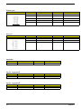
Revision History
Please refer to the table below for the updates made on Aspire SA90/AcerPower S290 service guide.
Date
II
Chapter
Updates
Copyright
Copyright © 2005 by Acer Incorporated. All rights reserved. No part of this publication may be reproduced,
transmitted, transcribed, stored in a retrieval system, or translated into any language or computer language, in
any form or by any means, electronic, mechanical, magnetic, optical, chemical, manual or otherwise, without
the prior written permission of Acer Incorporated.
Disclaimer
The information in this guide is subject to change without notice.
Acer Incorporated makes no representations or warranties, either expressed or implied, with respect to the
contents hereof and specifically disclaims any warranties of merchantability or fitness for any particular
purpose. Any Acer Incorporated software described in this manual is sold or licensed "as is". Should the
programs prove defective following their purchase, the buyer (and not Acer Incorporated, its distributor, or its
dealer) assumes the entire cost of all necessary servicing, repair, and any incidental or consequential
damages resulting from any defect in the software.
Acer is a registered trademark of Acer Corporation.
Intel is a registered trademark of Intel Corporation.
Pentium 4 and Celeron are trademarks of Intel Corporation.
Other brand and product names are trademarks and/or registered trademarks of their respective holders.
III
Conventions
The following conventions are used in this manual:
IV
SCREEN
MESSAGES
Denotes actual messages that appear
on screen.
NOTE
Gives bits and pieces of additional
information related to the current
topic.
WARNING
Alerts you to any damage that might
result from doing or not doing specific
actions.
CAUTION
Gives precautionary measures to
avoid possible hardware or software
problems.
IMPORTANT
Reminds you to do specific actions
relevant to the accomplishment of
procedures.
Preface
Before using this information and the product it supports, please read the following general information.
1.
This Service Guide provides you with all technical information relating to the BASIC CONFIGURATION
decided for Acer's "global" product offering. To better fit local market requirements and enhance product
competitiveness, your regional office MAY have decided to extend the functionality of a machine (e.g.
add-on card, modem, or extra memory capability). These LOCALIZED FEATURES will NOT be covered
in this generic service guide. In such cases, please contact your regional offices or the responsible
personnel/channel to provide you with further technical details.
2.
Please note WHEN ORDERING FRU PARTS, that you should check the most up-to-date information
available on your regional web or channel. If, for whatever reason, a part number change is made, it will
not be noted in the printed Service Guide. For ACER-AUTHORIZED SERVICE PROVIDERS, your Acer
office may have a DIFFERENT part number code to those given in the FRU list of this printed Service
Guide. You MUST use the list provided by your regional Acer office to order FRU parts for repair and
service of customer machines.
V
Chapter 1 System Specifications 1
Features . . . . . . . . . . . . . . . . . . . . . . . . . . . . . . . . . . . . . . . . . 1
Mainboard Placement . . . . . . . . . . . . . . . . . . . . . . . . . . . . . . . 4
Block Diagram . . . . . . . . . . . . . . . . . . . . . . . . . . . . . . . . . . . . 5
Aspire SA90 Front Panel . . . . . . . . . . . . . . . . . . . . . . . . . . . . 6
Aspire SA90 Rear Panel . . . . . . . . . . . . . . . . . . . . . . . . . . . . . 7
AcerPower S290 Front Panel . . . . . . . . . . . . . . . . . . . . . . . . . 8
AcerPower S290 Rear Panel . . . . . . . . . . . . . . . . . . . . . . . . . 9
Hardware Specifications and Configurations . . . . . . . . . . . . 10
Power Management Function (ACPI support function) . . . . 15
Chapter 2 System Utilities 16
Entering Setup . . . . . . . . . . . . . . . . . . . . . . . . . . . . . . . . . . .
Product Information . . . . . . . . . . . . . . . . . . . . . . . . . . . . . . .
Standard CMOS Features . . . . . . . . . . . . . . . . . . . . . . . . . .
Advanced BIOS Features . . . . . . . . . . . . . . . . . . . . . . . . . . .
Integrated Peripherals . . . . . . . . . . . . . . . . . . . . . . . . . . . . .
Power Management . . . . . . . . . . . . . . . . . . . . . . . . . . . . . . .
PnP/PCI Configuration . . . . . . . . . . . . . . . . . . . . . . . . . . . . .
PC Health Status . . . . . . . . . . . . . . . . . . . . . . . . . . . . . . . . .
Frequency/Voltage Control . . . . . . . . . . . . . . . . . . . . . . . . . .
Load Default Settings . . . . . . . . . . . . . . . . . . . . . . . . . . . . . .
Set Supervisor/User Password . . . . . . . . . . . . . . . . . . . . . . .
Save & Exit Setup . . . . . . . . . . . . . . . . . . . . . . . . . . . . . . . . .
Exit Without Saving . . . . . . . . . . . . . . . . . . . . . . . . . . . . . . . .
17
19
20
22
25
26
29
30
31
32
33
34
35
Chapter 3 Machine Disassembly and Replacement 36
General Information . . . . . . . . . . . . . . . . . . . . . . . . . . . . . . .
Disassembly Procedure . . . . . . . . . . . . . . . . . . . . . . . . . . . .
AcerPower S290 Disassembly Procedure . . . . . . . . . . . . . .
Aspire SA90 Disassembly Procedure . . . . . . . . . . . . . . . . . .
37
38
39
46
Chapter 4 Troubleshooting 53
Chapter 5 Jumper and Connector Information 54
Jumper Setting . . . . . . . . . . . . . . . . . . . . . . . . . . . . . . . . . . . 54
Chapter 6 FRU(Field Replaceable Unit) List 63
Exploded Diagram . . . . . . . . . . . . . . . . . . . . . . . . . . . . . . . . 64
Parts . . . . . . . . . . . . . . . . . . . . . . . . . . . . . . . . . . . . . . . . . . . 66
1
Chapter 1
System Specifications
Features
Operating System
T
Microsoft Windows Vista (Home Basic, Home Premium, Buiness)
Processor
T
Socket Type : Intel® Socket T LGA 775 pin
T
Processor Type :
T
Intel® Core 2 Duo 755 FSB 1066/800/533 MHZ
T
Intel® Pentium 4/D 775 FSB 533/800MHz
T
Intel® Celeron D775 FSB 533MHz
Chipset
T
North Bridge : SiS 671/671FX
T
South Bridge : SiS968
T
Form Factor : Mirco ATX
T
Dimension/ Layer : 244mm x 244mm
PCB
Memory
T
Memory Type : DDRII 667/533/400
T
Support single channel 64 bit mode with maximum memory size up to 2GB
T
Support un-buffered DIMMs only
T
DIMM Slot : 2
T
Memorry Max. : Support 128MB, 256MB, 512MB and 1GB DDR memory technologies
T
Cpapcity :Up to 1 GB per DIMM with maximum memory size up to 2 GB
Graphics
T
SiS 671 Mirage 3 Graphics solution
T
DX9 Shader Model 2.0 Dual Pixel Shading pipeline support
T
1 VGA port on rear
PCI
T
Chapter 1
PCI Express Slot Type:
T
PCI Express x16 Slot Quantity: 1
T
PCI Express x1 Slot Quantity: 1
T
PCI Slot Type : PCI 2.3, 5V Slots
T
PCI Slot Quantity: 2
1
FDD
T
Slot Quantity : 1
T
Support 1.44MB 3.5” Devices
T
Slot Type: 40 pin PATA IDE slot
T
Slot Quantity: 1
T
Transfer rate support:
IDE
T
PIO mode: 0/1/2/3/4
T
ATA mode: 33/66/100 port supported
T
Slot Type: SATA slot
T
Slot Quantity: 2
T
Transfer rate support: SATA 1.5 Gb/s and SATA 3.0 Gb/s
T
Storage Type support: HDD/CD-ROM/CD-RW/DVD-ROM/DVD-RW/DVD+RW/DVD Dual/DVD
SuperMultiPlus
Audio
T
Audio Type : HD audio codec
T
Audio Channel : 7.1 channel
T
Audio Controller /Codec : Realtek ALC883(Co-lay with Realtek ALC888)
T
Support S/PDIF : S/PDIF out
T
ATAPI analog line-level stereo inputs for AUX_IN
T
Type : RealTek 8211B
T
Supports 10/100/1000MB Ethernet environment
T
Support power down mode
LAN
IEEE 1394 (Reserved)
T
IEEE 1394 Controller : Ti TSB43AB23PDTG4
T
IEEE 1394 Port : 1 for rear I/O port
T
On board connector: 1(2x5 pin)
T
Controller : SiS 968
T
USB Type : 2.0/1.1
T
Connectors Quantity:
USB
T
4 for rear I/O ports
T
On-board header : 2 for front daughter board / 1 for sharing 2 rear USB port)
BIOS
2
T
BIOS Type : Phoenix Award BIOS
T
4MB Flash BIOS
T
Award PnP BIOS compatible with SM BIOS 2.4
T
ACPI 2.0,
Chapter 1
T
Provides DMI 2.0, WFM 2.0, WOL, and SM Bus for system management.
I/O Connector
T
Controller : Super I/O ITE 8718F-EX with hardware monitor
Rear I/O Connector
T
1 PS/2 Keyboard Port, 1 PS/2 Mouse Port
T
1 Parallel Port, 1 Serial Port
T
1 VGA Port
T
1 10/100/1000 LAN Port
T
4 USB Ports
T
6 jacks follow HD audio definition
Onboard Connector
T
1 CPU socket
T
2 Memory slots
T
1 PCI Express x16 slot
T
1 PCI Express x1 slot
T
2 PCI slots
T
1 FDD slot
T
1 PATA IDE slot
T
2 SATA IDE connectors
T
3 2*5 pin Intel FPIO sepcification USB pin connectors.
T
1 2*5 pin Intel FPIO spec. Microphone In/Headphone Out pin connectors
T
1 serial port 2*5 pin connector
T
1 AUX-In 4pin connector
T
1 S/PDIF out 1*4pin connector
T
1 4pin CPU Fan connector
T
1 3pin system fan connector
T
1 24pin ATX interface PS3/PS2 SPS connector
T
1 2*7pin front panel IO header
T
2 reserved 2pin GPIO connector
T
1 on board buzzer
T
1 1*3 pin Clear COM pin
T
1 RM
T
Color management for on board connector
T
Reserve position for 1 2*5pin 1394 connector
T
Reserved 1 2*5pin IRDA
Power Supply
T
Chapter 1
PSP Type : 250W
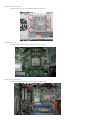
3
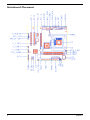
Mainboard Placement
4
Chapter 1
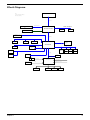
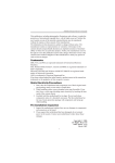
Block Diagram
LGA 775
Note:
Do not include the schematic
when create netlist.
Host Bus
Graphic Interface
PCI EXPRESS X16 SLOT
VB
DDR2 CHANNEL A
SiS671FX
DIMM 1
DIMM 2
VGA
PCI EXPRESS X1 SLOT
HyperZip
on board 1394
PCI SLOT 2
PCI SLOT 1
HD Audio
Codec
SiS968
SPI Bus
IDE 1
ROM
Serial ATA
USB 0
USB 2
USB 4
USB 6
USB 1
USB 3
USB 5
USB 7
LPC Bus
Serial ATA
LAN PHY
ROM
FAN
1
FAN
2
Fan Control
Voltage Monitor
LPC Super I/O
Temperature Monitor
KEYBOARD/MOUSE
PS/2
IR/CIR
Chapter 1
SERIAL
PARALLEL
FLOPPY
5
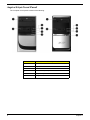
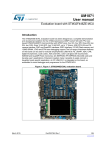
Aspire SA90 Front Panel
The computer’s front panel consists of the following:
No.
6
Description
Label
No.
Description
Description
1
Optical drive
2
Floppy disk drive
3
Power button
4
Speaker or headphone jack
5
Microphone jack
6
USB ports
Chapter 1
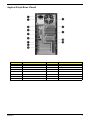
Aspire SA90 Rear Panel
No.
Description
No.
Chapter 1
Description
No.
Description
No.
Description
1
Power cord socket
2
Voltage selector switch
3
Fan aperture
4
PS/2 keyboard connector
5
PS/2 mouse connector
6
Serial port
7
Printer connector
8
Monitor connector
9
USB 2.0 ports
10
RJ-45 Ethernet connector
11
Microphone jack
12
Line-out Jack
13
Line-in jack
14
Extension card slots
7
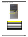
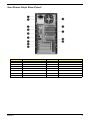
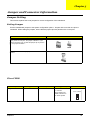
AcerPower S290 Front Panel
Label
8
Description
1
Power-Button
2
Speaker-out/Line-out Port
3
Microphone-in out ( Front )
4
USB Ports
5
Optical drive eject button
6
Optical drive
7
Power LED
8
HDD LED
9
Floppy drive eject button
10
Floppy disk drive
Chapter 1
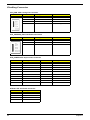
AcerPower S290 Rear Panel
No.
Chapter 1
No.
Description
Description
No.
Description
No.
Description
1
Power cord socket
2
Voltage selector switch
3
Fan aperture
4
PS/2 keyboard connector
5
PS/2 mouse connector
6
Serial port
7
Printer connector
8
Monitor connector
9
USB 2.0 ports
10
RJ-45 Ethernet connector
11
Microphone jack
12
Line-out Jack
13
Line-in jack
14
Extension card slots
9
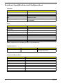
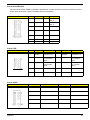
Hardware Specifications and Configurations
Processor
Item
Specification
Type
Intel Core 2 Duo / Intel Pentium 4/D / Intel Celeron
Socket
LGA 775
Speed
1.8~3.6G
FSB
1066/800/533 MHZ
Minimum operating speed
0 MHz (If Stop CPU Clock in Sleep State in BIOS Setup is
set to Enabled.)
BIOS
Item
Specification
BIOS code programmer
Award
BIOS version
v6.0
BIOS ROM type
Flash ROM
BIOS ROM size
4MB
BIOS ROM package
32-pin DIP package
Support protocol
PCI 2.3, APM1.2, DMI 2.00.1, ACPI 2.0, SMBIOS 2.4
Device Boot Support
HDD/CDROM/Remote Network/USB/USB Flash
Support to LS-120 drive
Yes
Support to BIOS boot block feature
Yes
NOTE: The BIOS can be overwritten/upgraded by using the flash utility.
BIOS Hotkey List
Hotkey
Function
Enter BIOS Setup Utility
c
Description
Press while the system is booting to
enter BIOS Setup Utility.
Main Board Major Chips
Item
10
Controller
NorthBridge
SiS 671/671FX
SourthBridge
SiS 968
AGP controller
SiS 671/671FX
Super I/O controller
ITE8718Ex
Audio controller
Realtek ALC883
LAN controller
Realtek 8211B
HDD controller
ITE8718Ex
Keyboard controller
ITE8718Ex
Chapter 1
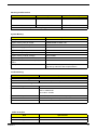
Memory Combinations
Slot
Memory Module
Total Memory
Slot 1
128, 256, 512MB, 1GB
128MB~ 1GB
Slot 2
128, 256, 512MB, 1GB
128MB~ 1GB
Maximum System Memory Supported
128MB~2GB
System Memory
Item
Specification
Memory slot number
2 slot
Support memory size per socket
128MB/256MB/ 512MB/ 1GB
Support maximum memory size
2GB
Support memory type
DDR DRAM
Support memory interface
DDRII 400 MHz
Support memory voltage
2.5 V
Support memory module package
184-pin DIMM
Support to parity check feature
Yes
Support to Error Correction Code (ECC)
feature
No
Memory module combinations
You can install memory modules in any combination as
long as they match the above specifications.
Cache Memory
Item
Specification
First-Level Cache Configurations
Cache function control
Enable/Disable by BIOS Setup
Second-Level Cache Configurations
L2 Cache RAM type
PBSRAM
L2 Cache RAM size
Celeron: 128K
Intel P4: 256K/512K
Core 2 Duo: 2/4 MB
L2 Cache RAM speed
One-half the processor core clock frequency
L2 Cache function control
Enable/Disable by BIOS Setup
L2 Cache scheme
Fixed in write-back
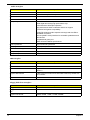
Audio Interface
Item
Specification
Audio controller
SiS 968
Audio controller Type
AC’97,ALC883
Chapter 1
11
Audio Interface
Item
Specification
Audio Channel
7.1ch
Audio function control
Enable/disable by BIOS Setup
Mono or stereo
Stereo
Resolution
20 bits
Compatibility
Sound Blaster Pro/16 compatible
Mixed digital and analog high performance chip
Enhanced stereo full duplex operation
High performance audio accelerator and AC’97 support
Full native DOS games compatibility
Virtual FM enhances audio experience through real-time FM-toWavetable conversion
MPU-401(UART mode) interface for wavetable synthesizers and
MIDI devices
Integrated dual game port
Meets AC’97and WHQL specifications
Music synthesizer
Yes, internal FM synthesizer
Sampling rate
48 KHz (max.)
MPU-401 UART support
Yes
Microphone jack
Supported
Headphone jack
Supported
IDE Interface
Item
Specification
IDE controller
SiS 968
IDE controller resident bus
PCI bus
Number of IDE channel
40 pin PATA x 1
SATA x 2
Support IDE interface
E-IDE (up to PIO mode-4 and Ultra DMA 33/66/100), ANSIS ATA
rev.3.0 ATAPI
Support bootable CD-ROM
Yes
Floppy disk drive Interface
Item
12
Specification
Floppy disk drive controller
ITE8718Ex
Floppy disk drive controller resident
bus
ISA bus
Support FDD format
360KB, 720KB, 1.2MB, 1.44MB, 2.88MB
Chapter 1
Parallel Port
Item
Specification
Parallel port controller
ITE8718Ex
Parallel port controller resident bus
ISA bus
Number of parallel ports
1
Support ECP/EPP
SPP / Bi-directional / ECP / EPP
Connector type
25-pin D-type female connector
Parallel port function control
Enable/disable by BIOS Setup
Optional ECP DMA channel
(in BIOS Setup)
DMA channel 1
DMA channel 3
Optional parallel port I/O address
(via BIOS Setup)
378h
278h
Optional parallel port IRQ
(via BIOS Setup)
IRQ5
IRQ7
Serial Port
Item
Specification
Serial port controller
ITE8718Ex
Serial port controller resident bus
ISA bus
Number of serial port
2
16550 UART support
Yes
Connector type
9-pin D-type female connector
Optional serial port I/O address
(via BIOS Setup)
COM1: 2F8h, 3E8h, 2E8h
COM2: 3E8h, 3F8h, 2F8h
Optional serial port IRQ
(via BIOS Setup)
COM1: IRQ 3, and 4
COM2: IRQ 4, and 3
USB Port
Item
Specification
Universal HCI
USB 2.0
USB Class
Support legacy keyboard for legacy mode
USB Connectors Quantity
4 for rear I/O ports, 3 on-board headers
Environmental Requirements
Item
Specifications
Temperature
Operating
+5°C ~ +35°C
Non-operating
-20 ~ +60°C (Storage package)
Humidity
Chapter 1
13
Environmental Requirements
Item
Specifications
Operating
15% to 80% RH
Non-operating
10% to 90% RH
Vibration
Operating (unpacked)
5 ~ 500 Hz:2.20g RMS random, 10 minutes per axis in all 3 axes
5 ~500 Hz: 1.09g RMS random, 1 hour per axis in all 3 axes
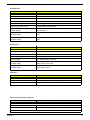
Power Management
S1
S3
S4
S5
Power Button
Devices
ν
ν
ν
ν
USB Keyboard /Mouse
ν
ν
N/A
N/A
Disabled
Disabled
Disabled
Disabled
PME
14
RTC
Disabled
Disabled
Disabled
Disabled
WOR
Disabled
Disabled
Disabled
Disabled
T
Devices wake up from S3 should be less than 5 seconds
T
Devices wak up from S5 should be less than 10 seconds
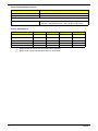
Chapter 1
Power Management Function (ACPI support function)
Device Standby Mode
T
Independent power management timer for hard disk drive devices
(0-15 minutes, time step=1 minute).
T
Hard disk drive goes into Standby mode (for ATA standard interface).
T
Disable V-sync to control the VESA DPMS monitor.
T
Resume method: device activated (Keyboard for DOS, keyboard & mouse for Windows).
T
Resume recovery time: 3-5 sec.
Global Standby Mode
T
Global power management timer (2-120 minutes, time step=10 minute).
T
Hard disk drive goes into Standby mode (for ATA standard interface).
T
Disable H-sync and V-sync signals to control the VESA DPMS monitor.
T
Resume method: Return to original state by pushing external switch button, modem ring in,
keyboard and mouse for APM mode.
T
Resume recovery time: 7-10 sec.
Suspend Mode
T
Independent power management timer (2-120 minutes, time step=10 minutes) or pushing external
switch button.
T
CPU goes into SMM.
T
CPU asserts STPCLK# and goes into the Stop Grant State.
T
LED on the panel turns amber colour.
T
Hard disk drive goes into SLEEP mode (for ATA standard interface).
T
Disable H-sync and V-sync signals to control the VESA DPMS monitor.
T
Ultra I/O and VGA chip go into power saving mode.
T
Resume method: Return to original state by pushing external switch button, modem ring in,
keyboard and mouse for APM mode.
T
Return to original state by pushing external switch button, modem ring in and USB keyboard for
ACPI mode.
T
ACPI specification 1.0b.
T
S0, S1, S3 and S5 sleep state support.
T
On board device power management support.
T
On board device configuration support.
ACPI
Chapter 1
15
Chapter 2
System Utilities
Most systems are already configured by the manufacturer or the dealer. There is no need to run
Setup when starting the computer unless you get a Run Setup message.
The Setup program loads configuration values into the battery-backed nonvolatile memory called CMOS RAM.
This memory area is not part of the system RAM.
NOTE: If you repeatedly receive Run Setup messages, the battery may be bad/flat. In this case, the system
cannot retain configuration values in CMOS.
Before you run Setup, make sure that you have saved all open files. The system reboots immediately after you
exit Setup.
Chapter 2
16
Entering Setup
Power on the computer and the system will start POST (Power On Self Test)process. When the message of
“Press DEL to enter SETUP” appears on the screen, press the key of [Delete] to enter the setup menu.
NOTE: If the message disappears before you respond and you still wish to enter Setup, restart the system by
turning it OFF and On. You may also restart the system by simultaneously pressing [Ctrl+Alt+Delete].
The Setup Utility main menu then appears:
Phoenix - AwardBIOS CMOS Setup Utility
XProduct Information
XStandard CMOS Features
XAdvanced BIOS Features
XAdvanced Chipset Features
XIntegrated Peripherals
XPower Management Setup
XPnP/PCI Configuration
XPC Health Status
XFrequency/Voltage Control
Load Optimized Defaults
Set Supervisor Password
Set User Password
Save & Exit Setup
Exir Without Saving
Esc: QuitKLIJ :Select Item
F10: Save & Exit Setup
Product name, System S/N ….
The command line at the bottom of the menu tells you how to move within a screen and from one screen to
another.
T
To select an option, move the highlight bar by pressing
T
To change a parameter setting, press
T
Press
to return to the main menu. If you are already in the main menu, press
exit Setup.
or
or
then press
.
until the desired setting is found.
again to
The parameters on the screens show default values. These values may not be the same as those in your
system.
The grayed items on the screens have fixed settings and are not user-configured.
NOTE: Due to the application of a new version of BIOS Setup program, you may find the BIOS menu is largely
different from the former models. However, you will soon find out that this version is much more
compact than the former ones.
17
Chapter 2
The items in the main menu are explained below:
T
Product Information
To introduce the Product Name,System P/N and MainBoard ID...etc.
T
Standard CMOS Features
The basic system configuration can be set up through this menu.
T
Advanced BIOS Features
The advanced system features can be set up through this menu.
T
Advancted Chipset Features
The values for the chipset can be changed through this menu, and the system performance can be
optimized.
T
Integrated Peripherals
All onboard peripherals can be set up through this menu.
T
Power Management Setup
All the items of Green function features can be set up throgh this menu.
T
PnP/PCI Configurations
The system’s PnP/PCI settings and parameters can be modified through this menu.
T
PC Health Staus
This will display the current status of your PC.
T
Frequency/Voltage Control
Frequency and voltage settings can be loaded through this menu.
T
Load Default Settings
These parameter settings can be loaded through this menu, however, the stable default values
may be affected.
T
Set Supervisor/User Password
The supervisor/user password can be set up through this menu.
T
Save & Exit Setup
Save CMOS value settings to CMOS and exit setup.
T
Exit Without Saving
Abandon all CMOS value changes and exit setup.
Chapter 2
18
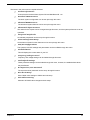
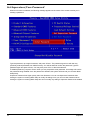
Product Information
The screen below appears if you select Product Information from the main menu:
The Product Information menu contains general data about the system, such as the product name, serial
number, BIOS version, etc. These information is necessary for troubleshooting (maybe required when
asking for technical support).
Phoenix - AwardBIOS CMOS Setup Utility
Product Information
ASSA90/APS290
F671FXCR
Product Name
Main Board ID
System S/N
Main Board S/N
System Manufacture Name
MB Manufacture Name
System BIOS Version
SMBIOS Version
System BIOS ID
BIOS Release Date
Help Item
Acer
Acer
6.00 PG
2.4
687A1D11
01/08/2007
KLIJ :Move Enter: Select +/-/ :Value F10:Save ESC:Exit F1:General Help
F5:Previous Values F7:Optimized Defaults
The following table describes the parameters found in this menu:
Parameter
19
Description
Product Names
Displays the model name of your system.
System S/N
Displays your system’s serial number.
Main Board ID
Displays the main board’s identification number.
Main Board S/N
Displays your main board’s serial number.
System BIOS Version
Specifies the version of your BIOS utility.
SMBIOS version
The System Management Interface (SM) BIOS allows you to check your system
hardware components without actually opening your system. Hardware
checking is done via software during start up. This parameter specifies the
version of the SMBIOS utility installed in your system.
BIOS Release Date
Displays the BIOS latest release date
Chapter 2
Standard CMOS Features
Select Standard CMOS Features from the main menu to configure some basic parameters in your system.
The following screen shows the Standard CMOS Features menu:
XDate (MM:DD:YY):
XTime (HH:MM:SS):
Phoenix - AwardBIOS CMOS Setup Utility
Standard CMOS Features
Sat. Jan 7 2006
22 : 36 : 36
XIDE Channel 0 Master
XIDE Channel 0 SLave
XSATA Channel 1 Master
XSATA Channel 2 Master
Drive A
3 Mode
Video
Halt On
Base Memory
Extended Memory
Total Memory
[HL-DT-STDVD-ROM GDR8]
[None]
[None]
[None]
Help Item
Use [ENTER], [TAB]
or [SHIFT-TAB] to
select a field
Use [+] or [-] to
configure system Date
[None]
[Disabled]
[EGA/VGA]
[All, But Keyboard]
640K
457728K
458752K
KLIJ :Move Enter: Select +/-/ :Value F10:Save ESC:Exit F1:General Help
F5:Previous Values F7:Optimized Defaults
The following table describes the parameters found in this menu. Settings in boldface are the default and
suggested settings.
Parameter
Date
Description
Lets you set the date following the weekdaymonth-day-year format
Options
Weekday: Sun, Mon...Sat
Month: Jan., Feb...Dec.
Day: 1 to 31
Year: 1999 to 2098
Time
Lets you set the time following the hour-minutesecond format
Hour: 0 to 23
IDE Channel 0/1 Master/Slave/
Leave this item at Auto to enable the system to
automatically detect and configure IDE devices
on the channel. If it fails to find a device, change
the value to Manual and then manually configure
the drive by entering the characteristics of the
drive in the items described below. Please noted
that if you choose IDE Channel 2/3 Master, the
item may change to Extended IDE Drive.
IDE Device Model Number:
None
SATA Channel 1/2 Master
This item display the status of auto detection of
SATA devices.
Drive A
Allows you to configure your floppy drive A.
Minute: 0 to 59
Second: 0 to 59
None
360 KB, 5.25-inch
1.2 MB, 5.25-inch
720 KB, 3.5-inch
1.44M, 3.5 - inch
2.88 MB, 3.5-inch
Chapter 2
20
Parameter
Drive B
Description
Allows you to configure your floppy drive B.
Options
None
360 KB, 5.25-inch
1.2 MB, 5.25-inch
720 KB, 3.5-inch
1.44M, 3.5 - inch
2.88 MB, 3.5-inch
Floppy 3 Mode Support
Floppy 3 mode refers to a 3.5-inch diskette with
a capacity of 1.2 MB. Floppy 3 mode is
sometimes used in Japan.
Disabled
Video
This item specifies the type of video card in use.
The default setting is VGA/EGA. Since current
PCs use VGA only, this function is almost
useless and may be disregarded in the future.
VGA/EGA
This parameter enables you to control the
system stops in case of Power On Self Test
errors (POST).
All Errors
Halt On
CGA40
CGA80
Mono
No Errors
All, but Keyboard
All, but Diskette
All, by Disk/Key
21
Base Memory
Refers to the option of memory that is available
to standard DOS programs. DOS systems have
an address space od 1MB, but the top 384KB
(called high memory) is reserved for system use.
This leaves 640 KB of conventional memory.
Everything above 1MB is either extended or
extended memory.
The BIOS POST will determine
the amount of base (or
conventional) memory installed
in the sytem.
Extended Memory
Memory above and beyond the standard 1MB of
base memory that DOS supports. Extended
memory is only available in PCs with an Intel
80286 or later microprocessor. Extended
memory is not configured in any special manner
and is therefore unavailable to most DOS
programs. However, MS Windows and OS/2 can
use extended memory.
The BIOS determines how much
extended memory is present
during the POST.
Total Memory
Total based and extended memory, and I/O ROM
384KB available to the system.
total memory of the system.
Chapter 2
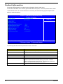
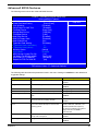
Advanced BIOS Features
The following screen shows the Advanced BIOS Features:
Phoenix - AwardBIOS CMOS Setup Utility
Advanced BIOS Features
XCPU Feature
[Press Enter]
XHard Disk Boot Priority
[Press Enter]
Virus Warning
[Disabled]
Quick Power On Self Test
[Enabled]
First Boot Device
[Hard Disk]
Second Boot Device
[CDROM]
Third Boot Device
[LAN]
Boot Other Device
[Enalbed]
Boot Up Floppy Seek
[Disabled]
Boot Up NumLock
[On]
Typematic Rate Setting
[Disabled]
x Typematic Rate (Chars/Sec)
6
x Typematic Delay (Msec)
250
Security Option
[Setup]
APIC Mode
Enabled
MPS Version Control For OS
[1.4]
OS Select For DRAM>64MB
[Non-OS2]
HDD S.M.A.R.T Capability
[Disabled]
Report No FDD For WIN 95
[No]
Help Item
KLIJ :Move Enter: Select +/-/ :Value F10:Save ESC:Exit F1:General Help
F5:Previous Values F7:Optimized Defaults
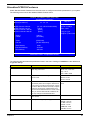
The following table describes the parameters found in this menu. Settings in boldface are the default and
suggested settings.
Parameter
Silent Boot
Description
Display Full Screen LOGO during POST
Options
Enabled
Disabled
Configuration Table
Enable the Configuration Table function
Enabled
CPU Feature
Select to display CPU Feature
Press [Enter]
Hard Disk Boot Priority
Select Hard Disk Boot Device Priority
Press [Enter]
Virus Warning
Enable this item to detect the virus in POST
mode.
Enabled
Quick Power On Self Test
This parameter speeds up POST by skipping
some items that are normally checked.
Enabled
First /Second/Third Boot
Device
The items allow you to set the sequence of boot
device where BIOS attempts to load the disk
operating system.
Floppy, LS120, Hard Disk, CD-ROM,
ZIP100, USB-FDD, USB-ZIP, LAN,
Disabled (Disable this sequence).
Disabled
Disabled
Disabled
The sequence following the order of
Floppy, HDD and CD-ROM is
recommended.
Boot Other Device
This parameter allows you to specify the system
boot up search sequence.
Enabled
Swap Floppy Drive
Setting to Enabled will swap floppy drive a: and
b:.
Enabled
Chapter 2
Disabled
Disabled
22
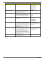
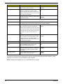
Parameter
Boot Up Floppy Seek
Boot Up NumLock Status
Typematic Rate Setting
Typematic Rate (Chars/Sec)
Typematic Delay (Msec)
Description
Options
Setting to Enabled will make BIOS seek floppy
drive a: before booting the system.
Enabled
Sets the NumLock status when the system is
powered on. Setting to On will turn on the
NumLock key when the system is powered on.
Setting to Off will allows users to use the arrow
keys on the numeric keypad.
On
This item is used to enable or disable the
typematic rate setting including Typematic Rate
and Typematic Delay.
Enabled
Disabled
Off
Disabled
Use this item to define how many characters per second are generated by a held-down
key.
Use this item to define how many milliseconds
must elapse before a held-down key begins generating repeat characters.
Security Option
Specifies the type of BIOS password protection
Setup
that is implemented. Setup means that the
System
password prompt appears only when end users
try to run Setup. System means that a password
prompt appears every time when the computer
is powered on or when end users try to run
Setup.
APIC Mode
This field is used to enable or disable the APIC
(Advanced Programmable Interrupt Controller).
Due to compliance with PC2001 design guide,
the system is able to run in APIC mode.
Enabling APIC mode will expand available IRQ
resources from the system.
Enabled
Disabled
MPS Version Control For OS This item displays MPS version control for OS.
1.4
OS Select For DRAM >
64MB
This item is only required if you have installed
more than 64MB of memory and you are
running the OS/2 operating system.
Non-OS2
HDD S.M.A.R.T Capability
The S.M.A.R.T (Self-Monitoring, Analysis, and
Reporting Technology) system is a diagnostics
technology that monitors and predicts device
performance.
Enabled
This item determines whether the BIOS will be
copied to RAM for faster execution.
Enabled
Video BIOS Shadow
OS2
Disabled
Disabled
The advanced chipset features setup option is used to change the values of the chipset registers. These
registers control most of the system options in the computer.
NOTE: Change these settings only if you are familiar with the chipset.
23
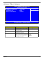
Chapter 2
Advanced Chipset Features
Phoenix - AwardBIOS CMOS Setup Utility
Advanced Chipset Features
XInternal Graphic Control
[Press Enter]
X DRAM Clock/Timing Control
[Press Enter]
AGP Aperture Size
[64MB]
Memory Hole at 15M-16M
[Disabled]
Help Item
KLIJ :Move Enter: Select +/-/ :Value F10:Save ESC:Exit F1:General Help
F5:Previous Values F7:Optimized Defaults
Parameter
Description
Option
Internal Graphic Control
This submenu is used to set some
parameters of graphice memory controller.
[Press Enter]
AGP Aperture Size
This item define the size of aperture if you
use a graphics adapter
32,64,128,256,512 MB
OnChip AGP Control
This submenu is used to set some
parameters of on board VGA
[Press Enter]
Memory Hole at 15M-16M
In order to improve performance, certain
space in memory is reserved for ISA cards.
This memory must be mapped into the
memory space below 16MB.
15-16MB
Chapter 2
14-16MB
Disabled
24
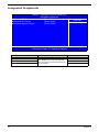
Integrated Peripherals
Phoenix - AwardBIOS CMOS Setup Utility
Integrated Peripherals
XOnboard IDE Device
[Press Enter]
XOnboard PCI Device
[Press Enter]
XOnboard SuperIO Device
[Press Enter]
Help Item
KLIJ :Move Enter: Select +/-/ :Value F10:Save ESC:Exit F1:General Help
F5:Previous Values F7:Optimized Defaults
Parameter
Onboard IDE Device
Onboard PCI Device
Onboard Super IO Device
25
Description
Use the arrow keys to select your options;
press <Enter> key to enter the setup submenu. The options and setting methods are
discussed below.
Option
[Press Enter]
[Press Enter]
[Press Enter]
Chapter 2
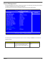
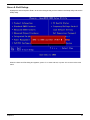
Power Management
The Power Management menu lets you configure your system to most effectively save energy while operating
in a manner consistent with your own style of computer use.
The following screen shows the Power Management parameters and their default settings:
Phoenix - AwardBIOS CMOS Setup Utility
Power Management Setup
ACPI function
[Enabled]
ACPI Suspend Type
[S3(STR)]
Video Off in Suspend
[Yes]
Video Off Method
[V/H SYNC+Blank]
MODEM Use IRQ
[AUTO]
HDD Power Down
[Disabled]
Soft-off by PWR-BTTN
[Delay 4 Sec]
PWRON After PWR-Fail
[Former-Sts]
Power On By Ring
[Disabled]
Wakeup By LAN PME
[Disabled]
LAN Remote WakeUp
[Disabled]
Wakeup By USB KB/MS
[Enabled]
Wakeup By PS2 KB/MS
[Enabled]
Resume by Alarm
[Disabled]
x Month Alarm
NA
x Day of Month Alarm
0
x Time (hh:mm:ss) Alarm
0:0:0
HPET Support
[Enabled]
Help Item
KLIJ :Move Enter: Select +/-/ :Value F10:Save ESC:Exit F1:General Help
F5:Previous Values F7:Optimized Defaults
The following table describes the parameters found in this menu. Settings in boldface are the default and
suggested settings.
Parameter
ACPI Function
Chapter 2
Description
This item is to activate the ACPI (Advanced
Configuration and Power Management Interface)
Function. If your operating system is ACPI
aware, such as Windows 98SE/2000/Me, select
Enabled.
Options
Enabled
Disabled
26
Parameter
ACPI Suspend Type
Suspend Mode
Video Off Option
Description
Options
This item specifies the power saving modes for
ACPI function. S1(POS): The S1 sleep mode is a
low power state. In this state, no system context
(CPU or chipset) is lost and hardware maintains
all system context. S3 (STR): The S3 sleep
mode is s power-down state in which power is
supplied only to essential components such as
main memory and wake-capable devices and all
system context is saved to main memory. The
information stored in memory will be used to
restore the PC to the previous state when an
wake-up event occurs. S1&S3: Both S1 and S3
will be adopted.
S1 (POS)
The CPU clock will be stopped and the video
signal will be suspended if no Power
Management events occur for a specified length
of time. Full power function will return when a
Power Management event is detected.
Disabled
This option is used to set video off option. The
setting values are always on, suspend> off,
susp,stby>off, and all modes>off.
Always On
This item determines the manner in which the
monitor is blanked.
Blank Screen
V/H SYNC+Blank: This selection will cause the
system to turn off the vertical and horizontal
synchronization ports and write blanks to the
video buffer. Blank Screen: This option only write
blanks to the video buffer. DPMS Supported:
Initial display power management signaling.
DPMS
This setting names the interrupt request (IRQ)
line assigned to the modem (if any) on your
system. Activity of selected IRQ always awakens
the system.
Auto
This option is used to define the continuous HDD
Disabled
idle time before the HDD enters power saving
1,2,3,4,5,6,7,8,9,10,11,12,13,
14,15 Min
S3 (STR)
S1&S3
1/2/4/8/12/20/30/40 mins
1 Hour
Suspend --> Off
Susp, Stby --> Off
All Modes --> Off
Video Off Method
Mode Use IRQ
HDD Power Down
mode. The setting values are disabled and 1 min
V/H SYNC+Blank
3,4,5,7,9,10,11
to 15 min.
Soft-off by PWR-BATTN
This option is used to set the power down
Instand Off
method. This function is only valid for systems
Delay 4 Sec.
using an ATX power supply. When ““nstant off” is
selected, press the power switch to immediately
turn off power. When “delay 4 sec” is selected,
press and hole the power button for four seconds
to turn off power.
PWRON After PWR-Fail
27
This item allow user set the machine power state
when connect the AC power. "Always off" means
the machine is always off when power on;
"Always on" means the machine will always
power on when connect the AC power; "PreState" means the machine state is the same as
the last state.
Always Off
Always On
Pre-State
Chapter 2
Parameter
Description
Options
PM Wake Up Events
Disabled: The specified event's activity will not
affect the PM Timers/wake up the system.
Enabled: The specified event's activity will affect
the PM Timers/wake up the system.
For example, if you have a modem on IRQ3, you
can turn On IRQ3 as a wake-up event, so an
interrupt from the modem can wake up the
system. Or you may wish to turn Off IRQ12 (the
PS/2) mouse as a wake-up event, so accidentally
brushing the mouse does not awaken the
system.
[Press Enter]
Delay Prior to Thermal
Enables you to set the delay time before the
CPU enters auto thermal mode
None
Chapter 2
1/2/4/8/16/32/64 Min
28
PnP/PCI Configuration
Phoenix - AwardBIOS CMOS Setup Utility
PnP/PCI Configurations
PCI/VGA Palette Snoop
[Disabled]
** PCI Express relative items **
Maximum ASPM supported
Masimum Payload Size
Help Item
[L0s&L1]
[4096]
KLIJ :Move Enter: Select +/-/ :Value F10:Save ESC:Exit F1:General Help
F5:Previous Values F7:Optimized Defaults
Parameter
Reset Configuration Data
Resources Controlled By
Description
Selecting “Enabled” to reset Extended System
Configuration Data (ESCD) only if you installed
a new add-on and the system reconfiguration
has caused such a serious conflict that the
operating system can not boot. Otherwise, you
should leave it unchanged.
Disabled
This BIOS can automatically configure all of the
boot and Plug and Play compatible devices. You
can also set it as Manual and go into each of the
sub menu to choose specific resources.
Auto (ESCD)
Enabled
Manual
IRQ Resources
The items are adjustable only when “Resources Press Enter
Controlled By” is set to Manual. By pressing
“Enter” to access the sub menu.
PCI/VGA Palette Snoop
Disabled - Data read or written by the CPU is
only directed to the PCI VGA device’s palette
registers.
Enabled - Data read or written by the CPU is
directed to both the PCI VGA device’s palette
registers and the ISA VGA device’s palette
registers, permitting the palette registers of both
VGA devices to be identical.
Maximum Payload Size
29
Options
This item specifies the maximum payload size
for the PCI Express function.
Disabled
Enabled
*If any ISA bus adapter in the
system requires VGA Palette
snooping, the setting must be set
to “Enabled”.
4096
Chapter 2
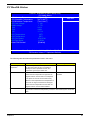
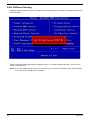
PC Health Status
Phoenix - AwardBIOS CMOS Setup Utility
PC Health Status
CPU Warning Temperature
[70oC/158oF]
CPU Shutdown Temperature
[90oC/194oF]
SYS Shutdown Temperature
[70oC/194oF]
CPU core voltage
1.16V
DIMM voltage
1.77V
3.3V
3.31V
5.0V
4.89V
12V
11.71V
CPU Temperature
35oC
SYS Temperature
38oC
CPU Fan Speed
976 RPM
SYS Fan Speed
0 RPM
Smart FAN Control
[Enabled]
Help Item
KLIJ :Move Enter: Select +/-/ :Value F10:Save ESC:Exit F1:General Help
F5:Previous Values F7:Optimized Defaults
The following table describes the parameters found in this menu:
Parameter
CPU Warning
Temperature
Smart FAN Control
Description
Options
This item lets you select the temperature at which
you want the system to send out a warning
message to the PC speakers of when the
temperature goes beyond either limit.
Disabled
Enable smart fan control function.
Enabled
--When the CPU temperature is higer than 65
Disabled
degrees Celsius, CPU fan will run at full speed.
--The speed of CPU fan will increase linearly
depand on the temperature if the temperature is
more than 41 degree and less than 65 degree.
--When the CPU temperature is lower than 40
degrees Celsius, CPU fan will be disable.
CPU Shutdown Temp.
Chapter 2
This option is for setting the shutdown temperature level for the processor. When
the processor reaches the temperature you set, the ACPI-aware system will be shut
down.
30
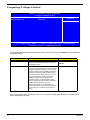
Frequency/Voltage Control
Phoenix - AwardBIOS CMOS Setup Utility
Frequency/Voltage Control
Auto Detect DIMM/PCI Clk
[Enabled]
Spread Spectrum
[Enabled]
Help Item
KLIJ :Move Enter: Select +/-/ :Value F10:Save ESC:Exit F1:General Help
F5:Previous Values F7:Optimized Defaults
The following table describes the parameters found in this menu. Settings in boldface are the default and
suggested settings.
Parameter
Auto Detect DIMM/PCI Clk
Spread Spectrum
Description
Options
This option allows you to enable/disable the
feature of auto detecting the clock frequency of
the installed PCI bus.
Enabled
When the motherboard’s clock generator pulses,
the extreme values (spikes) of the pulses creates
EMI (Electromagnetic Interference). The spread
Spectrum function reduces the EMI generated by
modulating the pulses so that the spikes of the
pulses are reduced to flatter curves. If you do not
have any EMI problem, leave the setting at
Disabled for optimal system stability and
performance. But if you are plagued by EMI,
setting to Enabled for EMI reduction. Remember
to disable Spread Spectrum if you are
overlocking because even a slight jitter can
introduce a temporary boost in clockspeed which
may just cause your overlock ed processor to
lock up.
Enabled
Disabled
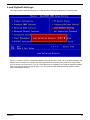
when your hardware does not support them. If you only want to install setup defaults for a specific option,
select and display that option.
31
Chapter 2
Load Default Settings
This option opens a dialog box that lets you install defaults for all appropriate items in the Setup Utility.
Press <Y> and then <Enter> to install the defaults. Press <N> and then <Enter> to not install the defaults. The
defaults place demands on the system that may be greater than the performance level of the components,
such as the CPU and the memory. You can cause fatal errors or instability if you install the optimized defaults
when your hardware does not support them. If you only want to install setup defaults for a specific option,
select and display that option.
Chapter 2
32
Set Supervisor/User Password
When this function is selected, the following message appears at the center of the screen to assist you in
creating a password.
Type the password, up to eight characters, and press <Enter>. The password typed now will clear any
previously entered password from CMOS memory. You will be asked to confirm the password. Type the
password again and press <Enter>. You may also press <Esc> to abort the selection.
To disable password, just press <Enter> when you are prompted to enter password. A message will confirm
the password being disabled. Once the password is disabled, the system will boot and you can enter BIOS
Setup freely.
Supervisor Password has higher priority than User Password. You can use Supervisor Password when
booting the system or entering BIOS Setup to modify all settings. Also you can use User Password when
booting the system or entering BIOS Setup but can not modify any setting if Supervisor Password is enabled.
33
Chapter 2
Save & Exit Setup
Highlight this item and press <Enter> to save the changes that you have made in the Setup Utility and exit the
Setup Utility.
When the Save and Exit dialog box appears, press <Y> to save and exit, or press <N> to return to the main
menu.
Chapter 2
34
Exit Without Saving
Highlight this item and press <Enter> to discard any changes that you have made in the Setup Utility and exit
the Setup Utility.
When the Exit Without Saving dialog box appears, press <Y> to discard changes and exit, or press <N> to
return to the main menu.
NOTE: If you have made settings that you do not want to save, use the "Exit Without Saving" item and press
<Y> to discard any changes you have made.
35
Chapter 2
Chapter 3
Machine Disassembly and Replacement
To disassemble the computer, you need the following tools:
T
Wrist grounding strap and conductive mat for preventing electrostatic discharge.
T
Wire cutter.
T
Phillips screwdriver (may require different size).
NOTE: The screws for the different components vary in size. During the disassembly process, group the
screws with the corresponding components to avoid mismatches when putting back the components.
Chapter 3
36
General Information
Before You Begin
Before proceeding with the disassenbly procedure, make sure that you do the following:
37
1.
Turn off the power to the system and all peripherals.
2.
Unplug the AC adapter and all power and signal cables from the system.
Chapter 3
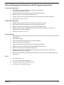
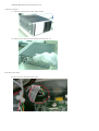
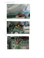
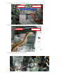
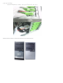
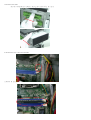
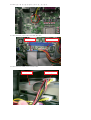
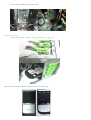
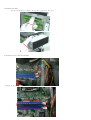
Disassembly Procedure
This section tells you how to disassemble the system when you need to perform system service. Please also
refer to the disassembly video, if available.
CAUTION: Before you proceed, make sure you have turned off the system and all peripherals connected to it.
Chapter 3
38
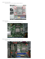
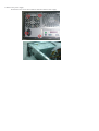
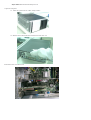
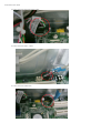
AcerPower S290
!
"
#
&
$ %
'
(
(
)
(
(
*
+
(
&!
,
'
- !
. $
/%
!
,
012
!
3!
!
,
(
(
(
"
. $
!
. $
!
4
"
,
. $
,
(
(
(
"
/%
#!
,
(
!
(
(
(
"
(
Aspire SA90
!
"
# $
AcerPower S290
%
%
& #'
%%
%(
) *
%+
%,
-
%.
-
-
%/
+"
0
-
& !
1
&
,
2 "
3 )
4*
"
1
5 6
"
7"
1
-
-
$
3 )
"
%"
-
3 )#
$
1
3 )
1
"
8
-
-
-
$
4*
("
1
"
-
-
-
$
-
Chapter 4
Troubleshooting
Please refer to generic troubleshooting guide for trougleshooting information relating to following topics:
Chapter 4
T
Power-On Self-Test (POST)
T
POST Check Points
T
POST Error Messages List
T
Error Symptoms List
53
Chapter 5
Jumper and Connector Information
Jumper Setting
This section explains how to set jumpers for correct configuration of the mainboard.
Setting Jumper
Use the motherboard jumpers to set system configuration options. Jumpers with more than one pin are
numbered. When setting the jumpers, ensure that the jumper caps are placed on the correct pins.
Description
Illustration
The illustrations show a 2-pin jumper. When the jumper
cap is placed on both pins, the jumper is SHORT. If you
remove the jumper cap, or place the jumper cap on just one
pin, the jumper is OPEN.
SHORT
OPEN
This illustration shows a 3-pin jumper. Pins 1 and 2 are
SHORT
Clear CMOS
Jumper
CLR_CMOS
Type
3-pin
Description
CLEAR CMOS
Setting(Default)
Illustration
1-2 : Clear
2-3 : Normal
Before clearing the
CMOS,make sure to
turn off the system
Clear CMOS
1
Chapter 5
54
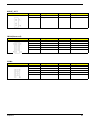
Checking Connector
CPU_FAN: CPU Cooling Fan Connector
Pin
Signal Name
Function
1
GND
System Ground
2
+12V
Power +12V
3
Sense
Sensor
4
Control
FAN Control Signal
SYS_FAN/PWR_FAN: FAN Power Connectors
Pin
Signal Name
Function
1
GND
System Ground
2
+12V
Power +12V
3
Sense
Sensor
ATX_POWER: ATX 20-pin Power Connector
Pin
Signal Name
Pin
11
Signal Name
1
+3.3V
+3.3V
2
+3.3V
12
-12V
3
Ground
13
Ground
4
+5V
14
PS ON#
5
Ground
15
Ground
6
+5V
16
Ground
7
Ground
17
Ground
8
PWRGD
18
-5V
9
+5VSB
19
+5V
10
+12V
20
+5V
ATX12V: ATX 12V Power Connector
Pin
55
Signal Name
1
Ground
2
Ground
3
+12V
4
+12V
Chapter 5
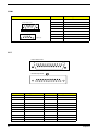
Front Panel Header
The front panel header (PANEL1) provides a standard set of switch and LED connectors commonly found on
ATX or Micro ATX cases. Refer to the table below for information:
Illustration
Pin
Pin
Signal
1
5V_SYS
Signal
2
GPIO_GRN_
HDR_R
3
HDD_LED_R
4
GPIO_YLW_
HDR_R
5
GND
6
PSIN
7
ICH_SYS_RS
TJ
8
GND
9
5V_SYS
10
KEY
11
NC
12
5V_SB
13
NC
14
LAN_ACTJ
Front USB
Illustration
Pin
Signal
1
VREG_FP_U
SBPWR0
3
USB_FP_P0-
Function
Pin
Signal
Function
Front panel USB
power(Ports 0,1)
2
VREG_FP_U
SBPWR0
Front panel USB
power(Ports 0,1)
Front panel USB
Port 0 Negative
Signal
4
USB_FP_P1-
Front panel USB
Port 1 Negative
Signal
5
USB_FP_P0+ Front panel USB
Port 0 Positive
Signal
6
USB_FP_P1+ Front panel USB
Port 1 Positive
Signal
7
GROUND
8
GROUND
9
KEY
10
GROUND
Front Audio
Illustration
Front Audio
Chapter 5
Pin
Signal Name
Pin
Signal Name
1
MIC2-L
2
AUD_GND
3
MIC2-R
4
AUD_PRESENCE_L
5
LINE2-R
6
MIC2-JD
7
FRONT-IO-SENSE
8
KEY
9
LINE2-L
10
LINE2-JD
56
Front 1394
Illustration
Pin
Signal Name
Pin
Signal Name
1
TPA+
2
TPA-
3
GROUND
4
GROUND
5
TPB+
6
TPB-
7
+12V(FUSED)
8
+12V(FUSED)
9
KEY
10
GROUND
Aux_In
Illustration
Pin
Signal Name
Pin
Signal Name
1
CD_IN_L
2
GROUND
3
GROUND
4
CD_IN_R
5
KEY
Intruder
Pin
1
Signal Name
INTRUDERJ
Pin
2
Signal Name
GROUND
J3(for requested)
Pin
1
Signal Name
AGPIO1
Pin
2
Signal Name
GROUND
J4(for requested)
Pin
1
57
Signal Name
AGPIO2
Pin
2
Signal Name
GROUND
Chapter 5
SPDIF_OUT
Illustration
Pin
Signal Name
Pin
Signal Name
1
5V_SYS
2
KEY
3
SPDIF_OUT
4
GND
IRDA(Reserved)
Illustration
Pin
Signal Name
Pin
Signal Name
1
5V_SB
2
IR_26
3
SIO_RSMRSTJ
4
RESETCONJ
5
IR_20
6
IR_27
7
IR_RE
8
IR_21
9
GND
10
KEY
COM2
Illustration
Chapter 5
Pin
Signal Name
Pin
Signal Name
1
NDCDB
2
NSINB
3
NSOUTB
4
NDTRB
5
GND
6
NDSRB
7
NDSRB
8
NCTSB
9
NRIB
10
KEY
58
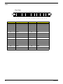
COM1
Illustration
Pin
Front Side View
1
2
6
3
7
DCD
2
RxD
3
TxD
4
DTR
5
Ground
6
DSR
7
RTS
8
CTS
9
RI
5
4
8
Signal Name
1
9
Pinout Top-View
Figure-(2)
LPT
Front Side View
Pinout Top-View
Pin
59
Signal Name
Pin
Signal Name
1
STROBE
13
SLCT
2
PD0
14
ALF
3
PD1
15
ERROR
4
PD2
16
INIT
5
PD3
17
SLCTIN
6
PD4
18
Ground
7
PD5
19
Ground
8
PD6
20
Ground
9
PD7
21
Ground
10
ACK
22
Ground
11
BUSY
23
Ground
Chapter 5
Pin
12
Chapter 5
Signal Name
PE
Pin
Signal Name
24
Ground
25
Ground
60
FDD
(Top-View)
2
4
6
8
10
12
14
16
18
20
22
24
26
28
30
32
34
1
3
5
7
9
11
13
15
17
19
21
23
25
27
29
31
33
Pin
61
Signal Name
Pin
2
Signal Name
1
Ground
DRVDEN0
3
Ground
4
HDL-
5
Keypin
6
DS3-
7
Ground
8
INDEX-
9
Ground
10
MTR0-
11
Ground
12
DS0-
13
Ground
14
DS1-
15
Ground
16
MTR1-
17
Ground
18
DIR-
19
Ground
20
STEP-
21
Ground
22
WDATA
23
Ground
24
WGATE-
25
Ground
26
TRK0-
27
Ground
28
WP-
29
Ground
30
RDATA
31
Ground
32
HDSEL-
33
Ground
34
DSKCHG-
Chapter 5
IDE1
(Top-View)
2
4
1
3
Pin
Chapter 5
6
5
8
7
10
9
12
11
Signal Name
14
13
16
15
18
17
20
22
19
21
24
23
26
28
25
30
27
Pin
29
32
31
34
33
36
35
38
37
40
39
Signal Name
1
RESET-
2
Ground
3
DD7
4
DD8
5
DD6
6
DD9
7
DD5
8
DD10
9
DD4
10
DD11
11
DD3
12
DD12
13
DD2
14
DD13
15
DD1
16
DD14
17
DD0
18
DD15
19
Ground
20
Keypin
21
DMARQ
22
Ground
23
DIOW-
24
Ground
25
DIOR-
26
Ground
27
IORDY
28
PSYNC:CSEL
29
DMACK-
30
Ground
31
INTRQ
32
IOCS16-
33
DA1
34
PDIAG-
35
DA0
36
DA2
37
CS1FX-
38
CS3FX-
39
DASP-
40
Ground
62
Chapter 6
FRU (Field Replaceable Unit) List
This chapter gives you the FRU (Field Replaceable Unit) listing in global configurations of
Aspire SA90/ AcerPower S290. Refer to this chapter whenever ordering for parts to repair or for RMA
(Return Merchandise Authorization).
NOTE: Please note WHEN ORDERING FRU PARTS, that you should check the most up-to-date information
available on your regional web or channel (http://aicsl.acer.com.tw/spl/, if you do not own a specific
account, you can still access the system with guest; guest). For whatever reasons a part number
change is made, it will not be noted in the printed Service Guide. For ACER-AUTHORIZED SERVICE
PROVIDERS, your Acer office may have a DIFFERENT part number code to those given in the FRU list
of this printed Service Guide. You MUST use the local FRU list provided by your regional Acer office to
order FRU parts for repair and service of customer machines.
Chapter 6
63
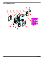
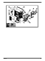
Exploded Diagram
64
Chapter 6
Chapter 6
65
Parts
The spare parts will be updated later.
66
Chapter 6