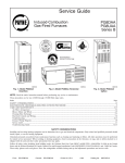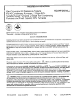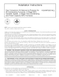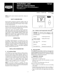
1
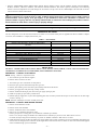
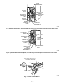
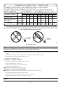
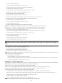
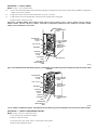
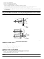
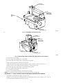
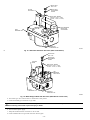
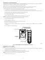
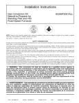
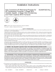
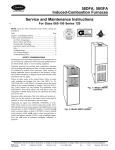
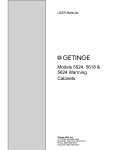
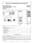
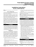
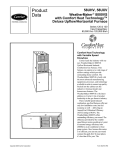
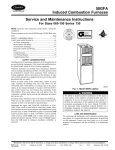
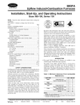
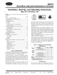
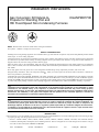
Installation Instructions
Gas Conversion Kit Natural-toKGANP2801F80
Propane for Standing Pilot and
HSI Fixed-Speed Non-Condensing Furnaces
CERTIFIED
NOTE: Read the entire instruction manual before starting the installation.
This symbol → indicates a change since the last issue.
SAFETY CONSIDERATIONS
Installing and servicing heating equipment can be hazardous due to gas and electrical components. Only trained and qualified personnel should
install, repair, or service heating equipment.
Untrained personnel can perform basic maintenance functions such as cleaning and replacing air filters. All other operations must be performed
by trained service personnel. When working on heating equipment, observe precautions in the literature, on tags, and on labels attached to or
shipped with the unit, and other safety precautions that may apply.
Follow all safety codes. In the United States, follow all safety codes including the National Fuel Gas Code (NFGC) NFPA No. 54-1999/ANSI
Z223.1-1999. In Canada, refer to the National Standard of Canada, Natural Gas and Propane Installation Codes (NSCNGPIC), CAN/CGA-B149.1
and .2-M00.
Wear safety glasses and work gloves. Have a fire extinguisher available during start-up, adjustment procedures, and service calls.
. When you see this symbol on the furnace and in instructions or manuals, be
Recognize safety information. This is the safety-alert symbol
alert to the potential for personal injury.
Understand the signal words DANGER, WARNING, CAUTION, and NOTE. The words DANGER, WARNING, and CAUTION are used with
the safety-alert symbol. DANGER identifies the most serious hazards which will result in severe personal injury or death. WARNING signifies
hazards which could result in personal injury or death. CAUTION is used to identify unsafe practices which would result in minor personal injury,
or product and property damage. NOTE is used to highlight suggestions which will result in enhanced installation, reliability, or operation.
WARNING: This conversion kit shall be installed by a qualified service agency in accordance with the manufacturer’s
instructions and all applicable codes and requirements of the authority having jurisdiction. If the information in these
instructions is not followed exactly, a fire, explosion, or production of carbon monoxide may result causing property
damage, personal injury, or loss of life. The qualified service agency is responsible for the proper installation of this furnace
with this kit. The installation is not proper and complete until the operation of the converted appliance is checked as
specified in the manufacturer’s instructions supplied with the kit.
AVERTISSEMENT: Cette trousse de conversion ne doit être installée que par le représentant d’un organisme qualifié
et conformément aux instructions du fabricant et à tous les codes et exigences pertinents de l’autorité compétente. Les
instructions du présent guide doivent être suivies afin de réduire au minimum au risque d’incendie ou d’explosion de
dommange matériels, de blessure ou de mort. L’organisme qualifié responsable de l’installation adéquate de cette trousse.
L’installation n’est pas adéquate ni complète tant que le bon fonctionnement de l’appereil converti n’a pas été vérfié selon
les instructions du fabricant fornies avec la trousse.
INTRODUCTION
→ This instruction covers the installation of gas conversion kit Part No. KGANP2801F80 to convert the following furnaces from natural gas usage
to propane gas usage. See the appropriate section for your furnace type.
• Section 1—Models 58DFA, 58GFA, 58PAP, 58RAP, 373LAD, 383KAD, 394HAD, 396HAD, GA1AAD, and GA2AAD InducedCombustion, Standing Pilot, Fixed-Speed, Non-Condensing Furnaces. This kit is designed for use in 065 through 150 size furnaces. The gas
valve will be either a Honeywell VR8200H or BR8300H.
Form:
AG-GANP-26
Cancels:
AG-GANP-24
Printed in U.S.A.
4-01
Catalog No.
63GA-NP7
•
Section 2—Models 58DHC, 58PAV, 58RAV, 58SSC, 58WAV, 58YAV, 58ZAV, 373LAV, 376CAV, 383KAV, 393AAV, 395CAV, 480BAV,
481BAV, GB1AAV, GB3AAV, PG8DAA, and PG8UAA Induced-Combustion, Hot Surface Ignition, Fixed-Speed, Non-Condensing
Furnaces. This kit is designed for use in 045 through 155 size furnaces. The gas valve will be a White-Rodgers 36E with either an electric
control switch or a manual control knob.
WARNING: Improper installation, adjustment, alteration, service, maintenance, or use can cause carbon monoxide
poisoning, explosion, fire, electrical shock, or other conditions which could result in personal injury or death. Consult a
qualified installer, service agency, local gas supplier, or your distributor or branch for information or assistance. The
qualified installer or agency must use only factory-authorized kits or accessories when modifying this product. Failure to
follow instructions could result in serious injury or property damage.
CAUTION: Gas supply MUST be shut off before disconnecting electrical power and proceeding with conversion.
DESCRIPTION AND USAGE
This kit is designed for use in the furnaces listed above. See Table 1 for kit contents. More parts are supplied in kit than are needed to complete
conversion; when installation is complete, discard extra parts.
Table 1 — Kit Contents
DESCRIPTION
Regulator Spring Kit (White—-Propane) for White-Rodgers
36E Valve
Regulator Spring Kit for Honeywell VR8200 Gas Valve
Pilot Orifice—-Honeywell
Main Burner Orifice (Drill Size No. 54)
Main Burner Orifice (Drill Size No. 55)
Main Burner Orifice (Drill Size No. 1.25 mm)
Conversion Rating Plate Label-NonCondensing Furnaces
Conversion Rating Plate Label-Condensing Furnaces
Conversion Responsibility Label
Gas Control Conversion Label
Installation Instructions
PART NO.
QUANTITY
EF39ZW023
1
EF39ZW025
LH32AN102
LH32DB203
LH32DB201
LH32DB209
326106-201
326106-203
326106-204
326106-202
AG-GANP-26
1
1
7
7
7
1
1
1
1
1
INSTALLATION
SECTION 1—MODELS 58DFA, 58GFA, 58PAP, 58RAP, 373LAD, 383KAD, 394HAD, 396HAD, GA1AAD, AND GA2AAD INDUCEDCOMBUSTION, STANDING-PILOT, FIXED-SPEED, NON-CONDENSING FURNACES
PROCEDURE 1—INSTALL PILOT ORIFICE
NOTE: See Fig. 1 and 2 for component location.
1. Turn off furnace gas and electrical supplies.
2. Remove furnace control access door.
3. Turn furnace gas valve control knob to OFF position.
4. Disconnect pilot gas tube and thermocouple from gas valve.
5. Remove pilot mounting screw and remove pilot assembly from burner and furnace.
6. Remove gas supply tube from pilot using a backup wrench.
7. Remove and discard natural gas pilot orifice from gas supply opening of pilot.
8. Install new propane gas pilot orifice provided in kit.
9. Reinstall pilot gas supply tube on pilot. When tightening pilot tube, use backup wrench and turn pilot so that it will be at the same angle
as before. (See Fig. 3.)
NOTE: DO NOT reinstall pilot on burner assembly at this time.
PROCEDURE 2—INSTALL MAIN BURNER ORIFICES
1. Remove burner hold-down bracket.
2. Remove burners from manifold.
3. Remove and discard orifices from manifold.
4. Refer to Fig. 4 to determine main burner orifice.
Furnace gas input rate on rating plate is for installations at altitudes up to 2000 ft.
In the U.S.A., the input rating for altitudes above 2000 ft must be reduced by 4 percent for each 1000 ft above sea level.
In Canada, the input rating must be derated by 10 percent for altitudes of 2000 ft to 4500 ft above sea level.
5. Install main burner orifices. DO NOT use Teflon tape. Finger-tighten orifices at least 1 full turn to prevent cross-threading, then tighten with
wrench. There are enough orifices in each kit for the largest furnace. Discard extra orifices. Orifices of other sizes must be field supplied
and are available through your local distributer.
—2—
BLOWER
COMPARTMENT
DOOR
CONVERSION
RATING
PLATE
GAS VALVE
BURNER
HOLD–DOWN
BRACKET
GAS CONTROL
CONVERSION
LABEL
FURNACE
RATING
PLATE
BURNERS
MANIFOLD
CLEARANCE
LABEL
CONVERSION
RESPONSIBILITY
LABEL
A95457
Fig. 1—Downflow, Standing-Pilot, Fixed-Speed, Non-Condensing Furnace Component and Conversion Label Location
CONVERSION
RATING
PLATE
GAS VALVE
GAS CONTROL
CONVERSION
LABEL
BURNER
HOLD–DOWN
BRACKET
BURNERS
FURNACE
RATING
PLATE
MANIFOLD
BLOWER
COMPARTMENT
DOOR
CLEARANCE
LABEL
CONVERSION
RESPONSIBILITY
LABEL
A95458
Fig. 2—Upflow, Standing-Pilot, Fixed-Speed, Non-Condensing Furnace Component and Conversion Label Location
PILOT HEAD V–NOTCH FALLS
DIRECTLY BELOW FRONT EDGE
OF BURNER CARRYOVER.
1/8″
A91249
Fig. 3—Position of Pilot to Burner
—3—
CONVERSION KIT RATING PLATE - CARRIER CORP.
THIS APPLIANCE HAS BEEN CONVERTED TO USE PROPANE GAS FOR FUEL. REFER TO KIT INSTRUCTIONS FOR CONVERSION
PROCEDURES. USE PARTS SUPPLIED BY CARRIER CORPORATION AND INSTALLED BY QUALIFIED PERSONNEL.
SEE EXISTING RATING PLATE FOR APPLIANCE MODEL NO. AND INPUT RATING.
NOTE: Furnace gas input rate on rating plate is for installations up to 2000 ft above sea level. In U.S.A. the input rating for altitudes above 2000 ft mus t
be derated by 4% for each 1000 ft above sea level. In Canada the input rating must be derated by 10% for altitudes of 2000 ft to 4500 ft above sea level.
INLET PRESSURE (min - max): 11.0 - 13.6 in. wc
FUEL USED: PROPANE GAS
ALTITUDE OF INSTALLATION (FT. ABOVE SEA LEVEL) U.S.A. *
KIT NO. KGANP2801F80
APPLIANCE MODELS
0
to 2000
2001 *
to 3000
3001
to 4000
4001
to 5000
5001
to 6000
6001
to 7000
7001
to 8000
8001
to 9000
54
11.0
55
11.0
55
11.0
55
10.5
55
10.0
1.25mm
11.0
1.25mm
10.5
1.25mm
10.0
373LAV, 376CAV, 481BAV, 58RAV,
58ZAV, GB3AAV, PG8DAA
Orifice No.
Mnfld Press
383KAV, 393AAV, 395CAV, 480BAV,
58PAV, 58WAV, 58YAV,
GB1AAV, PG8UAA
Orifice No.
54
55
55
1.25mm
1.25mm
Mnfld Press
10.0
10.5
10.0
11.0
11.0
1.25mm 1.25mm
Orifice No.
55
55
1.25mm 1.25mm 1.25mm
Mnfld Press
11.0
10.0
11.0
11.0
10.0
* For Canadian Installations from 2000 to 4500 ft use U.S.A. column 2001 to 3000 ft.
394HAD, 58GFA
10.5
56
11.0
10.0
56
11.0
9001
to 10000
56
11.0
56
56
11.0
10.0
56
10.0
57
11.0
326755-201 REV. A
A01083
→ Fig. 4—Conversion Rating-Plate Label–Non-Condensing Furnaces (Used for Orifice Size Selection for Propane, StandingPilot, Fixed-Speed, Non-Condensing Furnaces)
BURNER
ORIFICE
BURNER
ORIFICE
A96249
Fig. 5—Burner Orifice
CAUTION: DO NOT redrill burner orifices. Improper drilling (burrs, out-of-round holes, etc.) can cause excessive
burner noise and misdirection of burner flames. This can result in flame impingement of the burners and heat exchangers
causing failure. Obtain new orifices if orifice size must be changed. (See Fig. 5.)
6. Reinstall main burners on manifold. Burners should be installed left to right to ensure proper alignment of the burner cross-over slot. (See
Fig. 3.)
7. Reinstall pilot assembly on burner assembly. See Fig. 3 for proper orientation of burners and pilot.
8. Reconnect pilot supply tube and thermocouple to gas valve.
9. Reinstall burner hold-down bracket.
PROCEDURE 3—CONVERT GAS VALVE
1. Be sure main gas and electrical supplies to furnace are off.
2. Remove regulator seal cap. (See Fig. 6.)
3. Install propane gas regulator spring from Honeywell kit.
4. Replace regulator adjustment screw.
NOTE: DO NOT reinstall regulator seal cap at this time.
PROCEDURE 4—CHECK INLET GAS PRESSURE
NOTE: This kit is to be used only when inlet gas pressure is between 11.0-in. wc and 13.6-in. wc.
1. Be sure main gas and electric supplies to furnace are off.
2. Remove 1/8-in. pipe plug from inlet pressure tap on gas valve. (See Fig. 6.)
3. Attach manometer to inlet pressure tap on gas valve. (See Fig. 15.)
CAUTION: DO NOT operate furnace more than 1 minute to check inlet gas pressure as conversion is not complete at
this time.
—4—
4. Turn on furnace power supply.
5. Turn gas supply manual shutoff valve to ON position.
6. Turn furnace gas valve control knob to PILOT position and depress.
7. Check pilot tube connections for gas leaks.
8. Turn furnace gas valve control knob to OFF position and wait 5 minutes.
9. Light pilot in accordance with furnace lighting instructions.
10. Turn furnace gas valve switch to ON position.
11. Jumper R and W thermostat terminals to call for heat.
12. When main burners ignite, confirm inlet gas pressure is between 11.0-in. wc and 13.6-in. wc.
13. Remove jumper across R and W thermostat terminals to terminate call for heat.
14. Turn furnace gas valve switch to OFF position.
15. Turn gas supply manual shutoff valve to OFF position.
16. Turn off furnace power supply.
17. Remove manometer and reinstall gas valve inlet pressure tap plug.
NOTE: Use propane-gas-resistant pipe dope on all connections to prevent gas leaks. DO NOT use Teflon tape.
PROCEDURE 5—CHECK FURNACE OPERATION AND MAKE NECESSARY ADJUSTMENTS
1. Be sure main gas and electric supplies to furnace are off.
2. Remove 1/8-in. pipe plug from manifold pressure tap on downstream side of gas valve. (See Fig. 6.)
3. Attach manometer to manifold pressure tap on gas valve. (See Fig. 15.)
4. Turn gas supply manual shutoff valve to ON position.
5. Turn on furnace power supply.
6. Turn furnace gas valve control knob to ON position.
7. Check all threaded pipe connections for gas leaks.
WARNING: NEVER use matches, candles, flame, or other sources of ignition to check for gas leakage. Use a
soap-and-water solution to check for leaks. Failure to follow this warning could result in fire, explosion, personal injury, or
death.
8. Light pilot in accordance with furnace lighting instructions.
9. Turn furnace gas valve control knob to ON position
10. Jumper R and W thermostat terminals to call for heat.
11. When main burners ignite, check manifold orifices for gas leaks.
NOTE: The pilot flame should be soft blue in color and must provide good impingement on pilot thermocouple. The flame should extend above
burner carryover port to provide proper ignition.
12. If pilot flame requires adjustment:
a. Locate adjustment screw on top of gas valve. (See Fig. 6.)
b. Remove cap and turn adjustment screw clockwise (in) to decrease pilot gas flow and counterclockwise (out) to increase pilot gas flow.
c. When proper adjustment is obtained, replace screw cap.
PROCEDURE 6—SET GAS INPUT RATE
The gas input rate for propane is the same as for natural gas. See furnace rating plate for input rate. The input rate for propane is determined by
manifold pressure only. The gas valve regulator must be set per pressure stated in Fig. 4.
Furnace gas input rate on rating plate is for installations at altitudes up to 2000 ft.
In the U.S.A., the input rating for altitudes above 2000 ft must be reduced by 4 percent for each 1000 ft above sea level.
In Canada, the input rating must be derated by 10 percent for altitudes of 2000 ft to 4500 ft above sea level.
Furnace input rate must be within ±2 percent of input on furnace rating plate.
1. Turn adjustment screw counterclockwise to decrease manifold pressure or clockwise to increase manifold pressure.
2. When correct input is obtained, replace regulator seal cap. Main burner flame should be clear blue, almost transparent. (See Fig. 7.)
3. Remove jumper across R and W thermostat terminals to terminate call for heat.
4. Turn furnace gas valve control knob to OFF position.
5. Remove manometer and replace manifold pressure tap plug. (See Fig. 6.)
NOTE: Use propane-gas-resistant pipe dope to prevent gas leaks. DO NOT use Teflon tape.
—5—
6. Light pilot in accordance with furnace lighting instructions.
7. Turn furnace gas valve control knob to ON position.
8. Set room thermostat to call for heat.
9. Check manifold pressure tap plug for gas leaks when main burners ignite.
10. Check for correct burner flame. (See Fig. 7.)
11. Observe unit through 2 complete heating cycles. See sequence of operation in furnace Installation, Start-Up, and Operating Instructions.
12. Set room thermostat to desired temperature.
REGULATOR
SEAL CAP
REGULATOR
ADJUSTMENT
SCREW
REGULATOR
SPRING
MANUAL
ON/OFF
KNOB
MANIFOLD
PRESSURE
TAP
ON
INLET
PRESSURE
TAP
OFF
PILOT
CONNECTION
PILOT
PILOT
ADJUSTMENT
UNDER CAP
THERMOCOUPLE
CONNECTION
A89186
Fig. 6—Honeywell Gas Valve
PILOT FLAME
BURNER FLAME
BURNER
MANIFOLD
A84076
Fig. 7—Burner Flame
—6—
PROCEDURE 7—APPLY LABELS
NOTE: See Fig. 1 or 2 for label location.
→
→
→
1. Fill in Conversion Responsibility Label (326755-205) and apply to inside furnace casing as shown. Date, name, and address of organization
making conversion are required.
2. Apply Gas Control Conversion Label (326755-203) to gas valve as shown.
3. Apply Furnace Conversion Rating Plate (326755-201) near existing furnace rating plate.
4. Replace furnace control access door.
SECTION 2—MODELS 58DHC, 58PAV, 58RAV, 58SSC, 58WAV, 58YAV, 58ZAV, 373LAV, 376CAV, 383KAV, 393AAV, 395CAV,
480BAV, 481BAV, GB1AAV, GB3AAV, PG8DAA, AND PG8UAA INDUCED-COMBUSTION, HOT-SURFACE IGNITION, FIXEDSPEED, NON-CONDENSING FURNACES
BLOWER
COMPARTMENT
DOOR
CONVERSION
RATING
PLATE
GAS CONTROL
CONVERSION
LABEL
BURNER
HOLD–DOWN
BRACKET
GAS VALVE
BURNERS
FURNACE
RATING
PLATE
CLEARANCE
LABEL
MANIFOLD
CONVERSION
RESPONSIBILITY
LABEL
A95459
Fig. 8—Downflow/Horizontal Hot-Surface Ignition, Fixed-Speed, Non-Condensing Furnace Component and Conversion Label
Location
CONVERSION
RATING
PLATE
GAS CONTROL
CONVERSION
LABEL
GAS VALVE
BURNER
HOLD–DOWN
BRACKET
BURNERS
FURNACE
RATING
PLATE
MANIFOLD
BLOWER
COMPARTMENT
DOOR
CLEARANCE
LABEL
CONVERSION
RESPONSIBILITY
LABEL
A95460
Fig. 9—Upflow, Hot-Surface Ignition, Fixed-Speed, Non-Condensing Furnace Component and Conversion Label Location
PROCEDURE 1—INSTALL MAIN BURNER ORIFICES
NOTE: See Fig. 8 and 9 for component location.
1. Turn off furnace gas and electrical supplies.
2. Remove control access door.
3. Turn furnace gas valve control switch or control knob to OFF position.
4. Remove burner hold-down bracket.
—7—
5. Remove burners from manifold.
6. Remove and discard orifices from manifold.
7. Refer to Fig. 4 to determine main burner orifice.
Furnace gas input rate on rating plate is for installations at altitudes up to 2000 ft.
In the U.S.A., the input rating for altitudes above 2000 ft must be reduced by 4 percent for each 1000 ft above sea level.
In Canada, the input rating must be derated by 10 percent for altitudes of 2000 ft to 4500 ft above sea level.
8. Install main burner orifices. Finger-tighten orifices at least 1 full turn to prevent cross-threading, then tighten with wrench. There are enough
orifices in each kit for the largest furnace. Discard extra orifices. Orifices of other sizes must be field supplied and are available through
your local distributer.
CAUTION: DO NOT redrill burner orifices. Improper drilling (burrs, out-of-round holes, etc.) can cause excessive
burner noise and misdirection of burner flames. This can result in flame impingement of the burners and heat exchangers,
causing failures. Obtain new orifices if orifice size must be changed. (See Fig. 5.)
9. Reinstall main burners on manifold. Burners should be installed left to right to ensure proper alignment of the burner cross-over slot. (See
Fig. 10.)
10. Reinstall burner hold-down bracket.
11 32"
13 32"
BURNER
CELL
PANEL
HOT
SURFACE
IGNITOR
ASSEMBLY
C
L
7 8"
IGNITOR
C
L
BURNER
IGNITOR
ASSEMBLY
A96249
Fig. 10—Position of Ignitor to Burner
PROCEDURE 2—CONVERT GAS VALVE
1. Be sure gas and electrical supplies to furnace are off.
2. Remove regulator seal cap. (See Fig. 11, 12, 13, or 14.)
3. Remove adjustment screw and natural gas regulator spring (silver).
4. Install propane gas regulator spring (white) into gas valve.
5. DO NOT reinstall regulator seal cap at this time.
PROCEDURE 3—CHECK INLET GAS PRESSURE
NOTE: This kit is to be used only when inlet gas pressure is between 11.0-in. wc and 13.6-in. wc.
1. Remove 1/8-in. pipe plug from inlet pressure tap on gas valve. (See Fig. 11, 12, 13, or 14.)
2. Attach manometer to inlet pressure tap on gas valve.
CAUTION: DO NOT operate furnace more than 1 minute to check inlet gas pressure as conversion is not complete at
this time.
—8—
ON AND
OFF SWITCH
GAS
PRESSURE
REGULATOR
ADJUSTMENT
INLET
PRESSURE
TAP
MANIFOLD
PRESSURE TAP
A01082
→
Fig. 11—Redundant Automatic Gas Valve
ON AND
OFF SWITCH
GAS
PRESSURE
REGULATOR
ADJUSTMENT
INLET
PRESSURE TAP
MANIFOLD
PRESSURE TAP
A95618
Fig. 12—White-Rodgers Model 36E Gas Valve (With Electric Control Switch)
3. Turn on furnace power supply.
4. Turn gas supply manual shutoff valve to ON position.
5. Turn furnace gas valve control switch or control knob to ON position.
6. Jumper R and W thermostat connections to call for heat.
7. When main burners have ignited, confirm that inlet gas pressure is between 11.0-in. wc and 13.6-in. wc.
8. Remove jumper across R and W thermostat connections to terminate call for heat.
9. Turn furnace gas valve control switch or control knob to OFF position.
10. Turn gas supply manual shutoff valve to OFF position.
11. Turn off furnace power supply.
12. Remove manometer and reinstall gas valve inlet pressure tap plug.
NOTE: Use propane-gas-resistant pipe dope to prevent gas leaks. DO NOT use Teflon tape.
PROCEDURE 4—CHECK FURNACE OPERATION AND MAKE NECESSARY ADJUSTMENTS
1. Be sure main gas and electrical supplies to furnace are off.
2. Remove 1/8-in. pipe plug from manifold pressure tap on downstream side of gas valve. (See Fig. 11, 12, 13, or 14.)
3. Attach manometer to manifold pressure tap on gas valve.
—9—
REGULATOR
SEAL CAP
REGULATOR
ADJUSTMENT
SCREW
ON AND
OFF SWITCH
REGULATOR SPRING
(PROPANE – WHITE, 6 TURNS
NATURAL – SILVER, 10 TURNS)
GAS PRESSURE
REGULATOR
ADJUSTMENT
INLET
PRESSURE TAP
MANIFOLD
PRESSURE TAP
A01073
→
Fig. 13—Redundant Automatic Gas Valve (With On/Off Switch)
REGULATOR
SEAL CAP
REGULATOR
ADJUSTMENT
SCREW
CONTROL
KNOB
REGULATOR SPRING
(PROPANE – WHITE, 6 TURNS
NATURAL – SILVER, 10 TURNS)
OF
GAS
PRESSURE
REGULATOR
F
INLET
PRESSURE TAP
MANIFOLD
PRESSURE TAP
A93359
Fig. 14—White-Rodgers Model 36E Gas Valve (With Manual Control Knob)
4. Turn furnace gas valve control switch or control knob to ON position.
5. Check all threaded pipe connections for gas leaks.
WARNING: NEVER use a match or other open flame to check for leaks. Use a soap-and-water solution. Failure to
follow this warning could result in personal injury or death.
6. Turn on furnace power supply.
7. Jumper R and W thermostat connections to call for heat.
8. Check manifold orifices for gas leaks when main burners ignite.
—10—
PROCEDURE 5—SET GAS INPUT RATE
The gas input rate for propane is the same as for natural gas. See furnace rating plate for input rate. The input rate for propane is determined by
manifold pressure only. The gas valve regulator must be set per pressure stated in Fig. 4.
Furnace gas input rate on rating plate is for installations at altitudes up to 2000 ft.
In the U.S.A., the input rating for altitudes above 2000 ft must be reduced by 4 percent for each 1000 ft above sea level.
In Canada, the input rating must be derated by 10 percent for altitudes of 2000 ft to 4500 ft above sea level.
Furnace input rate must be within ±2 percent of input on furnace rating plate.
1. Turn adjusting screw counterclockwise to decrease manifold pressure or clockwise to increase manifold pressure.
2. When correct input is obtained, replace regulator seal cap. Main burner flame should be clear blue, almost transparent. (See Fig. 11 or 12.)
3. Remove jumper across R and W thermostat connections to terminate call for heat.
4. Turn furnace gas valve control switch or control knob to OFF position.
5. Turn off furnace power supply.
6. Remove manometer and replace manifold pressure tap plug. (See Fig. 11, 12, 13, or 14.)
NOTE: Use propane-gas-resistant pipe dope to prevent gas leaks. DO NOT use Teflon tape.
7. Turn furnace gas valve control switch or control knob to ON position.
8. Turn on furnace power supply.
9. Set room thermostat to call for heat.
10. Check manifold pressure tap plug for gas leaks when main burners ignite.
11. Check for correct burner flame. (See Fig. 7.)
12. Observe unit operation through 2 complete heating cycles. See sequence of operation in furnace Installation, Start-Up, and Operating
Instructions.
13. Set room thermostat to desired temperature.
BURNER ENCLOSURE
(REMOVE COVER WHEN
CHECKING PRESSURE)
GAS VALVE
PRESSURE
SWITCH
MANOMETER
7
6
5
4
3
2
1
0
1
2
3
4
5
6
7
A94351
Fig. 15—Adjusting Manifold Pressure (Manometer attachment)
PROCEDURE 6—APPLY LABELS
NOTE: See Fig. 8 or 9 for label location.
→
→
→
1. Fill in Conversion Responsibility Label (326755-205) and apply to inside furnace casing as shown. Date, name, and address of organization
making this conversion are required.
2. Apply Gas Control Conversion Label (326755-203) to gas valve as shown.
3. Apply Furnace Conversion Rating Plate (326755-201) near existing furnace rating plate.
NOTE: Discard labels and instructions packaged with White-Rodgers regulator.
4. Replace furnace control access door.
—11—
© 2001 CAC/BDP
P.O. Box 70, Indianapolis, IN 46206
agganp26
—12—
Book/Tab: 1/6a, 4/8a
Catalog No. 63GA-NP7