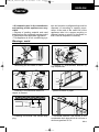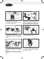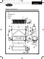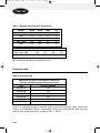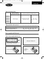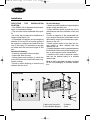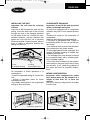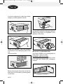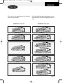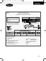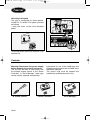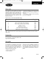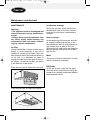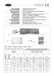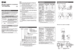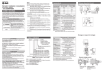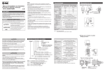
1
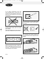
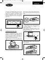
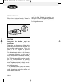
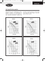
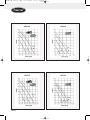
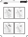
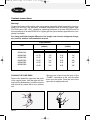
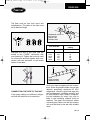
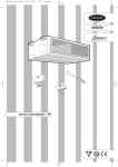
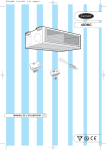
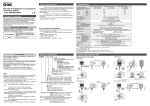
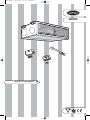
9-02-2005
15:06
Pagina 1
40DMC
GB
Y
R QUALIT
TE
SURANC
E
AS
D’S REG
OY
IS
LL
INSTALLATION MANUAL
¥
COP_BASE
IS O
900 1
COP_BASE
9-02-2005
15:06
Pagina 2
40DMC
GB
DUCT MOUNTABLE CEILING UNIT
40DMC_GB_install.qxd
27-09-2005
8:49
Pagina 1
ENGLISH
ENGLISH
DUCT MOUNTABLE CEILING UNIT
(cooling and heat pump heating mode only)
Contents
Safety precautions . . . . . . . . . . . . . . . . . . . . . . . . . . . . . . . . . . . . . . . . . . . . . .
Warnings: avoid . . . . . . . . . . . . . . . . . . . . . . . . . . . . . . . . . . . . . . . . . . . . . . . .
Weights and dimensions . . . . . . . . . . . . . . . . . . . . . . . . . . . . . . . . . . . . . . . .
Technical data . . . . . . . . . . . . . . . . . . . . . . . . . . . . . . . . . . . . . . . . . . . . . . . . .
Items supplied with the unit . . . . . . . . . . . . . . . . . . . . . . . . . . . . . . . . . . . . . . .
Installation . . . . . . . . . . . . . . . . . . . . . . . . . . . . . . . . . . . . . . . . . . . . . . . . . . . .
Unit specification graphs . . . . . . . . . . . . . . . . . . . . . . . . . . . . . . . . . . . . . . . . .
Coolant connections . . . . . . . . . . . . . . . . . . . . . . . . . . . . . . . . . . . . . . . . . . . .
Electrical connections . . . . . . . . . . . . . . . . . . . . . . . . . . . . . . . . . . . . . . . . . . .
Controls . . . . . . . . . . . . . . . . . . . . . . . . . . . . . . . . . . . . . . . . . . . . . . . . . . . . . .
Alarm code . . . . . . . . . . . . . . . . . . . . . . . . . . . . . . . . . . . . . . . . . . . . . . . . . . . .
Accessories . . . . . . . . . . . . . . . . . . . . . . . . . . . . . . . . . . . . . . . . . . . . . . . . . . .
User guide . . . . . . . . . . . . . . . . . . . . . . . . . . . . . . . . . . . . . . . . . . . . . . . . . . . .
Maintenance and disposal . . . . . . . . . . . . . . . . . . . . . . . . . . . . . . . . . . . . . . . .
Page
2
3
5
6
7
8
15
18
20
22
23
23
23
24
GB-1
40DMC_GB_install.qxd
27-09-2005
8:49
Pagina 2
Safety precautions
Read this instruction manual thoroughly before using the appliance.
Keep all installation, operating and
maintenance instructions carefully and
hand them on if you transfer the appliance to another owner.
This appliance conforms to the Low
Voltage Directive (73/23 EEC) and
Electromagnetic Compatibility Directive
(89/336 EEC).
It must be installed by qualified personnel only.
The appliance must be installed in an
area which is not accessible to the public.
WARNING! Always disconnect the
appliance from the mains supply before
starting any maintenance work and
before accessing any internal components.
• Follow all the precautions listed below.
They are essential to safety.
• Check that the appliance has not been
damaged in transit. If any damage is visible,
report it to the carrier immediately.
• Make sure that the voltage and frequency of the mains electricity supply correspond to the specifications on the appliance. Also make sure that the mains supply has sufficient installed power for the
appliance to operate simultaneously with
any other electrical appliances that might
be connected to the same power line.
• To avoid fire, explosion and injury, never
operate the appliance in the presence of
dangerous substances or near appliances
that produce naked flames.
• In particular make sure that the appliance is efficiently earthed.
• The system must be connected to the
mains electricity supply in accordance with
the wiring diagram in the outdoor section
installation manual.
• Make sure that the appliance is installed
in compliance with all applicable national
GB-2
safety standards.
• The appliance can only operate correctly
and without risk provided it has been
installed and tested by specialist personnel.
• After installation, carry out functional testing and instruct the user in the operation of
the system.
• This manual describes the installation of
the indoor unit of a split system consisting
of two Carrier units. Coupling different
units equipped with different control systems can damage the systems and invalidates the respective warranties. The manufacturer accepts no responsibility for system malfunctions deriving from unapproved coupling.
• The manufacturer declines all responsibility for damage or injury caused by unauthorised modifications to the appliance or
incorrect electrical or coolant connections.
• Failure to observe the instructions given
in this manual or use of the appliance in
conditions other than those specified in the
“Operating Limitations” table in the appliance’s installation manual automatically
invalidates the warranty.
• Only use the appliance for the purpose
for which it is intended. The indoor unit is
not suitable for use in washrooms.
• Do not use the appliance if it is damaged.
In the event of any malfunctioning, switch
the appliance off immediately and disconnect it from the mains electricity supply.
• Only qualified personnel are authorised to
clean inside or maintain the appliance.
• Arrange for periodic checks to be carried
out on the unit, the electrical connections,
the coolant pipes and the safety devices
(these operations must be carried out by
qualified personnel only).
• This appliance contains moving parts.
Make sure that children cannot get at
them.
40DMC_GB_install.qxd
27-09-2005
8:49
Pagina 3
ENGLISH
• All materials used in the manufacture
and packing of this appliance are recyclable.
• Dispose of packing material and used
batteries from the (optional) remote control
in compliance with applicable legislation.
• This appliance is an air conditioning sys-
tem and contains a refrigerant that must be
disposed of according to specific procedures. At the end of the useful life of the
appliance, take it to a proper recycling or
disposal centre or return it to the dealer so
that it can be disposed of correctly.
Warnings: avoid
... obstructing the air intake or outlet.
... installing in environments affected by
high frequencies.
... installing in environments where oil
vapour is present.
... partial insulation of pipes.
... installing out-of-level: this causes dripping.
... horizontal sections and bends in the
condensate drain pipe which do not have a
minimum gradient of 5%.
GB-3
40DMC_GB_install.qxd
27-09-2005
8:49
Pagina 4
... in cooling mode, direct entry of sunlight
into the room: draw the curtains.
... installing in places near heat sources,
which could damage the unit.
... routing the condensate drain pipe to a
residential drain or sewer network without
a siphon. The height of the siphon in relation to the available head must be such as
to allow correct evacuation of condensate.
... loose electrical connections.
... loosening the coolant connections after
connecting them (loss of refrigerant
charge).
... crushing the coolant connection pipes
and the condensate drain pipe.
... too many bends between indoor and outdoor units (see outdoor unit installation
manual).
Excessive distance between indoor and
outdoor units (see outdoor unit installation
manual).
... an excessive height difference between
the indoor and outdoor units (see outdoor
unit installation manual)
GB-4
40DMC_GB_install.qxd
27-09-2005
8:49
Pagina 5
ENGLISH
Weights and dimensions
1.
2.
3.
4.
5.
6.
7.
8.
9.
10.
Coil
Fan
Condensate collection tray
Drainage connection Ø AP
Fresh air intake
Electrical panel
Unit frame
Air filter
Liquid Ø AM
Gas Ø AN
GB-5
40DMC_GB_install.qxd
27-09-2005
8:49
Pagina 6
Table I: Weights and geometric dimensions
40DMC
018
024
028
ØAM
1/4”
1/4”
1/4”
ØAN
1/2”
1/2”
5/8”
ØAP
21
21
21
kg
32
35
35
036 - 052
060
3/8”
3/8”
3/4”
3/4”
21
21
48
53
40DMC
A
B
C
D
018 - 024 - 028
036 - 052 - 060
925
1325
971
1371
865
1265
779
1179
NB: All measurements are expressed in mm.
Technical data
Table II: Nominal data
Maximum electrical consumption values [W]
Cooling and heat pump heating mode only
Unit
Cooling / Heating
40DMC018
40DMC024
40DMC028
40DMC036
40DMC052
40DMC060
140
160
250
365
430
580
Notes: For sizing the system’s electrical supply cable and slow-blow fuses, consult the
outdoor unit installation manual. Consumption values are measured with free inlet and
outlet at High speed and with a voltage of 264 V ~ 50 Hz.
GB-6
40DMC_GB_install.qxd
27-09-2005
8:49
Pagina 7
ENGLISH
Table III: Operating limits
Operating temperature
(cooling only or heat pump)
Refer to the outdoor unit installation manual
40DMC018
40DMC024
40DMC028
Single phase rated voltage
Operating limit voltage
Electrical supply
40DMC036
230 V ~ 50 Hz
min 198 V - max 264 V
40DMC052
40DMC060
Table IV: Outdoor static pressure
40DMC0
18
24
28
36
52
60
Nominal static pressure (Pa)
Maximum pressure (Pa)
50
50
50
80
80
80
Refer to the “Installation” section
Items supplied with the unit
Table V: Items supplied with the unit
X5
DRILLING TEMPLATE
C
M
D
N
A
O
CH
ED
B
NL
M
P
DR
IF
T
T-
K
Ä
S
GB
YT
TÄ
GR
U
IE
O
N
IN
G
EN
O
N
D
A
ER
L
D
H
O
O
U
U
D
TI
LI
SK
ZA
KÖ
D
JÄ
TS
O
N
R
EL
K
IN
Ä
SI
ST
K
RU
IR
KT
JA
IO
N
40
I
FIN
A
L
U
E
R
W
SU
A
N
SA
U
H
D
A
U
EL
C
U
N
A
L
U
A
N
A
M
M
R
G
EB
IO
TE
N
LI
TE
SA
ATE
U
R
EI
SU
F
N
G
ER
O
W
N
D
EL
L’
U
A
LE
EL
M
D
E
A
N
U
L’
U
TI
E
D
N
A
IE
GR
K
FIN
’S
M
N
JÄ
M
N
U
A
E
M
D
EL
U
C
H
N
A
A
U
R
EB
G
M
M
“Use and
Maintenance”
Manual
L’
U
TI
A
LE
O
W
N
ER
’S
M
D
A
EL
N
U
L’
A
U
L
TE
N
LI
A
TE
SA
SA
N
ATE
U
N
A
I
W
L
U
R
EI
D
EL
SU
F
U
N
SU
G
A
D
R
IO
Ä
S
YT
TÄ
GB
P
DR
IF
T
T-
A
O
CH
N
U
O
NL
B
ED
N
IN
G
EN
Installation Manual
A
L
D
O
U
TI
LI
SK
ZA
KÖ
D
TS
O
R
EL
K
IN
Ä
SI
ST
K
RU
IR
KT
JA
IO
N
O
N
D
ER
H
O
U
D
40
D
M
C
Front enclosure panel with pre-scored holes
for duct connection + extra screws
GB-7
40DMC_GB_install.qxd
27-09-2005
8:49
Pagina 8
Installation
SELECTING
THE
INSTALLATION
POSITION
• The 40DMC unit is designed ducted installation in suspended ceilings.
• The unit must not be accessible to the public.
• As a rule, the unit cannot be installed at a
height of less than 2.5 m.
• It is possible to install the unit at a height of
between 2.2 m and 2.5 m from the ground if
the system is configured for intake from the
rear. In this case, it is necessary to provide
an intake duct with minimum length of 250
mm.
Avoid the following:
• Positions exposed to direct sunlight.
• Areas near heat sources.
• Damp places and positions in which the
unit could come into contact with water (e.g.
laundry rooms).
• Rooms in which shelving or furniture may
obstruct the flow of air.
Do the following:
• Select a position capable of supporting the
weight of the operating unit.
• Leave sufficient space around the unit for
maintenance and free circulation of air (see
figure).
• Leave an aperture in the suspended ceiling or ensure that a part of the latter can be
removed for carrying out maintenance operations on the unit.
• Select a place which is free from dirt, foreign bodies or other material that may
obstruct the coil.
• Suitable dampers must be placed between
the brackets of the unit and the hanging system so as to prevent noise transmission.
• Install the unit in such a way that condensate can be drained easily to a suitable
waste outlet.
Note: A drilling template has been provided
on the unit packaging to facilitate installation.
Service area
200
220
400
250 mm
Bars to be screwed in
Anti-vibration dampers
GB-8
Washer
Nut
40DMC_GB_install.qxd
27-09-2005
8:49
Pagina 9
ENGLISH
INSTALLING THE UNIT
Important: the unit must be correctly
levelled.
Insert the 4 M8 threaded tie rods into the
ceiling. Insert the other end of the tie rods
through the slots in the hanging brackets
on the sides of the unit. Position the antivibration dampers, add the washers and
tighten the nuts until the unit is correctly
fixed and levelled. If space permits, place a
layer of rubber or neoprene between the
ceiling and the unit.
Unit
Suspended ceiling
Ceiling
Removable cover
On completion of these operations it is
necessary to:
• install a suspended ceiling to conceal the
unit;
• include a removable panel for future
maintenance work;
• fit suitably sized grilles in the suspended
ceiling to allow air intake.
CONDENSATE DRAINAGE
Important: do not lift the unit by means
of the condensate drain pipe.
All units are equipped with a condensate
collection tray with 21 mm external Ø drain
pipe.
Therefore fit a pipe for the evacuation of
condensate.
Adhere to the following recommendations:
• Use pipes in galvanised steel, copper or
transparent plastic. Do not use normal garden hoses.
• Use material which ensures that the drain
pipe connections are totally sealed.
• If using rigid material for the outlet pipe, fit a
number of flexible couplings to absorb any
vibrations from the unit.
• The drainage line must always be below
the connection itself, with a suitable gradient to facilitate outflow.
• Pour a few litres of water into the condensate collection tray and check that it flows
out correctly. If not, check the gradient of
the pipes and look for possible obstructions.
INTAKE CONFIGURATION
Important: units configured for intake
from below must not be installed at a
height of less than 2.5 m from the
ground.
The unit is factory-configured for air intake
from the rear.
Minimum gradient 5%
GB-9
40DMC_GB_install.qxd
27-09-2005
8:49
Pagina 10
It can be configured for intake from below
simply by inverting panels A and B.
B
A
When fitting the rear panel, take care not to
damage the insulation of the pipes with the
edges of the panels. On completion of the
operation, fit the filter.
A
A
B
During the operation, take the following
precautions to avoid damaging parts of the
unit:
remove the filter.
AIR OUTLET CONFIGURATION
The Carrier 40DMC unit is predisposed for
either side or front air outlet.
Installation with front outlet
The standard factory configuration is with
front outlet and ducting with rectangular
conduits
Before removing the rear panel (A) pull the
drain pipe out of its seat by pressing gently
on the sides.
GB-10
40DMC_GB_install.qxd
27-09-2005
8:50
Pagina 11
ENGLISH
The unit can be predisposed for ducting
with circular conduits.
Each of the following configurations can be
executed with the items supplied with the
unit.
40DMC018, 024, 028
40DMC036, 052, 060
GB-11
40DMC_GB_install.qxd
27-09-2005
8:50
Pagina 12
Do not adopt configurations other than
those indicated above, as this may compromise the correct operation of the unit. In
particular, avoid operating the unit with just
one aperture.
After removing the cut-outs, make certain
that the insulation covers all the parts in
steel sheet.
Predisposition of the unit for circular
front outlets
The unit is supplied with a front enclosure
panel with 8” diameter circular cut-outs.
After removing the cut-outs, replace the
front panel of the unit.Also using the screws
supplied.
Before removing the cut-outs, cut the insulation on both sides of the panel with a suitable knife. This facilitates opening and prevents damage to the insulation.
GB-12
40DMC_GB_install.qxd
27-09-2005
8:50
Pagina 13
ENGLISH
60 mm
The area of the panel which can be used
for fixing the 8” circular flanges (not supplied) is as shown in the figure. Avoid
drilling or fastening screws in the shaded
area of the figure so as not to damage the
unit’s tray.
After removal, make certain that the insulation covers the steel sheet around the cut
area.
The area which can be used for fixing the
8” circular flanges (not supplied) is as
shown in the figure.
Avoid drilling or fastening screws in the
areas highlighted in the figure so as not to
damage the unit’s tray.
Installation with side outlet
The unit is predisposed so that it can be
installed in corridors to make optimum use
of the two circular outlets on the sides. In
order to prepare the unit for this type of
installation, proceed as follows:
remove the two cut-outs in the sides of the
unit.
60 mm
Replace the front panel of the unit with the
panel supplied.
GB-13
40DMC_GB_install.qxd
27-09-2005
8:50
Pagina 14
FRESH AIR INTAKE
There is a cut-out on the side of the unit,
which can be used as a fresh air intake. It
can be opened with a screwdriver.
DUCTING
Important: the ducting must be
designed and calculated by qualified
technicians.
Determine the dimensions of the ducts
according to the air flow rate required and
the available static pressure of the unit
(refer to the fan diagrams on previous
pages).
You are advised to adhere to the following
recommendations:
• regardless of the type of duct used, it
must not be made of inflammable material,
which produces toxic gases in the event of
fire. The internal surfaces must be smooth
and not contaminate the air passing
through them. You are advised to use
ducts in galvanised steel, suitably insulated, to prevent the formation of condensate
and thermal losses.
• The ducts should be joined with flexible
couplings which absorb vibrations, prevent
noise transmission inside the ducting and
allow access to the unit.
GB-14
• As far as possible, avoid bends near the
unit’s air outlet. If this is not possible, the
radius of curvature must be as wide as
possible; use internal deflectors if the duct
is of large dimensions.
40DMC_GB_install.qxd
26-09-2005
17:55
Pagina 15
ENGLISH
Unit specification graphs
Warning! The unit is configured for three
speeds, LO-ME-HI. On installations in
which it is necessary to set the speed S.HI
(see “electrical connections” section), the
minimum counter-pressure at the outlet
must reach the value shown in the diagrams below (see ★).
GB-15
40DMC_GB_install.qxd
GB-16
26-09-2005
17:55
Pagina 16
40DMC_GB_install.qxd
26-09-2005
17:55
Pagina 17
ENGLISH
GB-17
40DMC_GB_install.qxd
27-09-2005
8:50
Pagina 18
Coolant connections
Warning!
Connect the indoor and outdoor units using copper pipes with flared connections (not supplied). For the lines, use insulated, unwelded, degreased and de-oxidised copper pipe,
(Cu DHP type to ISO 1337), suitable for operating pressures of at least 4200 kPa and for
a burst pressure of at least 20700 kPa. Copper pipe for hydro-sanitary applications is completely unsuitable.
For sizing and limits (height difference, line length, max. bends, refrigerant charge,
etc.) see the outdoor unit installation manual.
Pipe diameter
Gas
(intake)
Unit
40DMC018
40DMC024
40DMC028
40DMC036
40DMC052
40DMC060
mm
inches
mm
inches
12.70
12.70
15.87
19.05
19.05
19.05
1/2”
1/2”
5/8”
3/4”
3/4”
3/4”
6.35
6.35
6.35
9.52
9.52
9.52
1/4”
1/4”
1/4”
3/8”
3/8”
3/8”
FLARING THE PIPE ENDS
Remove the protection caps from the ends
of the copper pipes. Hold the pipe with the
end pointing downwards, cut off the excess
and remove any swarf with a burr removal
tool.
GB-18
Liquid
(outlet)
Remove the unions from the body of the
“FLARE” connection of the unit and slide
them onto the pipes. Flare the end of the
pipe with an appropriate tool.
40DMC_GB_install.qxd
27-09-2005
8:50
Pagina 19
ENGLISH
L
L
The flare must be free from burrs and
imperfections. The walls of the flare must
be of identical length.
Adjustable wrench or
torque wrench
Indoor side
Outdoor side
Pipe diameter
Lubricate the end of the pipe and the
thread of the “FLARE” connection with
non-freezing oil. Tighten the union by hand
for a few turns and then tighten each connection with two wrenches, to the torque
shown in the table.
Torque
setting
mm
inches
Nm
6.35
9.52
12.70
15.87
19.05
1/4”
3/8”
1/2”
5/8”
3/4”
18
42
55
65
100
Pipe
Pipe insulation
Adhesive tape
CONNECTING THE PIPE TO THE UNIT
If the torque setting is insufficient, refrigerant fluid will leak from the connection.
Once you have completed all the connections, check for possible leaks using a leak
detector specifically designed for HFC
refrigerants. Clad the pipes and taps with
anti-condensation insulating material and
fix with adhesive tape, without compressing the insulation too much. Any cuts or
tears in the insulating material must be
repaired. The pipes and electrical cables
connecting the indoor unit with the outdoor
unit must be fixed to the wall with suitable
ducts.
GB-19
40DMC_GB_install.qxd
27-09-2005
8:50
Pagina 20
Electrical connections
Warning! Powering the unit with an
incorrect voltage invalidates the Carrier
warranty.
Important:
• The electrical connection of the system
must be made from the outdoor unit.
• To make the electrical connections for the
unit (cable entry, section of conductors,
safety devices, etc.), consult the electrical
data table and the wiring diagram attached
to the unit, and comply with the standards
in force for the installation of air conditioning appliances.
• The installer must install all the safety
devices in accordance with the legislation
in force.
EXECUTION
• Make the coolant connections first and
then the electrical connections. For disassembly, proceed in reverse order.
• Make the earth connection before the
electrical connections.
• Make the electrical connection between
the two units first and then make the connection to the mains electricity supply.
• For correct connection, refer to the wiring
diagrams in Figures A and B.
Cooling only
FIG. A
40DMC018, 024, 028, 036, 052,060
NOTES: Refer to the installation manual for the outdoor unit for connection
to the mains electricity supply.
Interconnection cable (H07RN-F)
interconnection between
indoor and outdoor unit (mm2)
model
40DMC018,024,028
40DMC036,052,060
GB-20
GND
R
4x1
C
Y
O W2 S V1 V2 V3 V4 40 41
Not connected
CRC
1
2
3
3 x 0.75
A03VV-F
40DMC_GB_install.qxd
27-09-2005
8:50
Pagina 21
ENGLISH
Heat pump heating mode
FIG. B
40DMC018, 024, 028, 036, 052,060
NOTES: Refer to the installation
manual for the outdoor unit for
connection to the mains electricity supply.
Interconnection cable (H07RN-F)
Interconnection cable (A07RN-F)
interconnection between
indoor and outdoor unit (mm2)
model
GND
40DMC018,024,028
40DMC036,052,060
R
3x1
C
Y
O W2 S V1 V2 V3 V4 40 41
4x1
Not connected
CRC
1
2
3
3 x 0.75
A03VV-F
Terminal board legend
Outdoor unit
Earth
R Line (phase) connection to outdoor unit
C Neutral, connection to outdoor unit
Y Compressor permissive
O Inversion valve control (heat pump only)
W2 Outdoor fan control
S End defrosting thermostat signal
V1, V2, V3, V4 Indoor fan speed
40, 41
Heating element control
1, 2, 3
Room Controller (CRC)
Room Controller (CRC)
P Power supply
G Earth
C Signal
GB-21
40DMC_GB_install.qxd
27-09-2005
8:50
Pagina 22
Selecting S.HI speed
The unit is configured for three speeds,
LO-ME-HI. To select S.HI speed, proceed
as follows:
• open the cover of the unit’s electrical
panel;
• move the brown cable from terminal V3 to
terminal V4;
• close the cover of the electrical panel.
Controls
Warning! Disconnect the power supply
before opening the control unit cover.
The unit can be used in conjunction with
the infrared remote control or the “Room
Controller” or “Zone Manager” cable type
remote control (optional accessories).
IR remote control
GB-22
Instructions for use of the cable-type and
infrared remote controls are included in the
respective manuals.
The control units must be opened and
installed by qualified personnel only.
“Room Controller”
“Zone Manager”
40DMC_GB_install.qxd
27-09-2005
8:50
Pagina 23
ENGLISH
Alarm code
The electronic card contains an internal
diagnostic system which supervises the
correct operation of the system. When the
diagnostic system enters an alarm state,
the red LED on the main electronic card
flashes as follows:
• sequence of flashes of 0.5 seconds ON
and 0.5 seconds OFF with an interval of 5
seconds.
• The number of flashes varies according
to the error diagnosed.
Not all errors can be reset (see table below).
Error code
Error
Resettable
*
3
Air temperature sensor
YES
4
Temp. sensor Indoor heat exchanger
YES
5
Temp. sensor Outdoor heat exchanger
YES
7
Outdoor unit error
YES
10
EEPROM corrupted
YES
11
Card serial number corrupted
YES
12
Address/zone number incomplete
YES
*NO: Unplug the system from the power supply, check and repair if necessary. Power up the system.
YES: Check
Accessories
For accessories, consult the product catalogue and documentation.
User guide
On completion of installation and with the
aid of the use and maintenance manual,
instruct the user in the correct operation of
the air conditioning system and how to
select the functions, such as:
Give the user the installation manuals for
the indoor and outdoor units and the use
and maintenance manual so that they can
be consulted for maintenance or other purposes.
• switch-on and switch-off;
• control functions.
GB-23
40DMC_GB_install.qxd
27-09-2005
8:50
Pagina 24
Maintenance and disposal
MAINTENANCE
Warning!
• The appliance must be maintained and
cleaned internally only by qualified personnel.
• Always disconnect the appliance from
the mains supply before starting any
maintenance work and before accessing any internal components.
Air filter
Check that the filter is clean at least once a
month or more frequently if the unit is
installed in a dusty environment. Dirt in the
filter reduces the air flow and the efficiency
of the unit. It is advisable to clean or
change the filter before the start of the winter season. To remove the filter, pull gently
in the direction of the arrow.
Filter removal with air intake from the rear
Filter removal with air intake from below
GB-24
Condensate drainage
During the summer, check that the condensate drain pipe is free from obstructions which could cause condensate to
overflow.
Heat exchanger
At the beginning of the summer and winter seasons, check that the fins on the
heat exchanger are not obstructed by foreign matter such as dust or fluff, etc..
Remove the air outlet grille and clean the
heat exchanger, taking care not to damage the fins.
Motor
The motor is life-time lubricated. No lubrication is therefore necessary.
DISPOSAL
At the end of their useful life, the appliance and all its components must be disposed of at a suitably authorised differentiated disposal centre.
COP_BASE
9-02-2005
GB
15:06
Pagina 3
The manufacturer reserves the right to change any product specifications without notice.tto
COP_BASE
14-02-2005
9:47
Pagina 4
Via R. Sanzio, 9 - 20058 Villasanta (MI) Italy - Tel 039/3636.1
Printed in Italy
Grafiche Nicolini - Gavirate (VA) - 0905
L010126H55-0905